Embed Size (px)
Citation preview

SOUTH COAST AIR QUALITY MANAGEMENT DISTRICT
METHOD 207.1
DETERMINATION OF AMMONIA EMISSIONS FROM STATIONARY SOURCES
SOURCE TEST ENGINEERING/ LABORATORY SERVICES
MONITORING AND ANALYSIS April 2006
SOUTH COAST AIR QUALITY MANAGEMENT DISTRICT
METHOD 207.1
DETERMINATION OF AMMONIA EMISSIONS FROM STATIONARY SOURCES
SOURCE TEST ENGINEERING/ LABORATORY SERVICES
MONITORING AND ANALYSIS April 2006
207.1-i
TABLE OF CONTENTS
PAGE
Table Of Contents ............................................................................................................................ i
List Of Figures ............................................................................................................................... iv
1.0 Overview................................................................................................................................. 1 1.1 Applicability ....................................................................................................................... 1 1.2 Principle .............................................................................................................................. 1 1.3 Method Performance........................................................................................................... 2
1.3.1 Accuracy ...................................................................................................................... 2 1.3.2 Precision....................................................................................................................... 2 1.3.3 Interferences................................................................................................................. 3 1.3.4 Range ........................................................................................................................... 3 1.3.5 Sample Storage Time................................................................................................... 3 1.3.6 Duplicate Sampling...................................................................................................... 3
2.0 Sampling Preparation.............................................................................................................. 4 2.1 Planning .............................................................................................................................. 4
2.1.1 Pre-Test Protocol (Optional)........................................................................................ 4 2.1.2 Sampling Technique .................................................................................................... 4 2.1.3 Field Blank Trains........................................................................................................ 5 2.1.4 Fixed Gases Measurement ........................................................................................... 5
2.2. Equipment.......................................................................................................................... 5 2.2.1 Greenburg-Smith Impinger Train ................................................................................ 5
2.2.1.1 Nozzle and Probe .................................................................................................. 5 2.2.1.2 Filter Holder.......................................................................................................... 6 2.2.1.3 Impinger Train ...................................................................................................... 6 2.2.1.4 Metering System ................................................................................................... 6
2.2.2 Mini-Impinger Train .................................................................................................... 7 2.2.2.1 Sampling Line....................................................................................................... 7 2.2.2.2 Impinger Train ...................................................................................................... 7 2.2.2.3 Metering System ................................................................................................... 8
2.3 Sampling Reagents ............................................................................................................. 8 2.3.1 Filters ........................................................................................................................... 8 2.3.2 Silica Gel...................................................................................................................... 8 2.3.3 Water............................................................................................................................ 8 2.3.4 0.1 N Sulfuric Acid Solution ....................................................................................... 8 2.3.5 Other Supplies.............................................................................................................. 8
Table of Contents, Continued PAGE
207.1-ii
2.4 Sample Train Assembly...................................................................................................... 9 2.4.1 Greenburg-Smith Train Assembly............................................................................... 9
2.4.1.1 Probe and Nozzle .................................................................................................. 9 2.4.1.2 Filter and Filter Holder ......................................................................................... 9 2.4.1.3 Impinger Train ...................................................................................................... 9
2.4.2 Mini-Impingers Train Assembly................................................................................ 10 2.4.2.1 Sampling Line..................................................................................................... 10 2.4.2.2 Mini-Impinger Train ........................................................................................... 10
3.0 Field Procedures.................................................................................................................... 11 3.1 Sampling With Greenburg-Smith Impinger Train............................................................ 11
3.1.1 Calibrations................................................................................................................ 11 3.1.2 Pre-Test Determinations ............................................................................................ 11 3.1.3 Field Train Assembly................................................................................................. 12 3.1.4 Pre-Test Leak Check.................................................................................................. 12 3.1.5 Sampling Operation ................................................................................................... 13 3.1.6 Post-Test Procedures.................................................................................................. 15
3.2 Mini-Impinger Train ......................................................................................................... 16 3.2.1 Calibrations................................................................................................................ 16 3.2.2 Pre-Test Determinations ............................................................................................ 17 3.2.3 Field Train Assembly................................................................................................. 17 3.2.4 Pre-Test Leak Check.................................................................................................. 17 3.2.5 Sampling Operation ................................................................................................... 17 3.2.6 Post-Test Procedures.................................................................................................. 18
4.0 Laboratory Procedures .......................................................................................................... 19 4.1 Sample Recovery .............................................................................................................. 19
4.1.1 Greenburg-Smith Impinger Train .............................................................................. 19 4.1.2 Mini-Impinger Train .................................................................................................. 20
4.2 Analysis ............................................................................................................................ 21 4.2.1 Equipment .................................................................................................................. 21 4.2.2 Reagents..................................................................................................................... 21 4.2.3 Calibration.................................................................................................................. 22 4.2.4 Analytical Procedure.................................................................................................. 23
4.2.4.1 Greenburg-Smith Impinger Train ....................................................................... 24 4.2.4.2 Mini-Impinger Train ........................................................................................... 25 4.2.4.3 Sample Dilutions................................................................................................. 26
Table of Contents, Continued PAGE
207.1-iii
4.3 Calculations ...................................................................................................................... 26 4.3.1 Calibration Standards................................................................................................. 26 4.3.2 Calibration Regression Line ...................................................................................... 27 4.3.3 Measured Concentration Of Ammonia...................................................................... 27 4.3.4 Average Measured Ammonia Concentration (Cavg) ................................................ 27 4.3.5 Relative Percent Difference (RPD)............................................................................ 27 4.3.6 Relative Percent Accuracy (RPA) ............................................................................. 28 4.3.7 Matrix Spike Percent Recovery (%R)........................................................................ 28
4.4 Quality Control ................................................................................................................. 28 4.4.1 Initial Calibration ....................................................................................................... 28 4.4.2 Calibration Verification ............................................................................................. 29 4.4.3 Measurement Stability ............................................................................................... 29 4.4.4 Matrix Spike Recovery .............................................................................................. 29 4.4.5 Temperature Probe..................................................................................................... 30
5.0 Emissions Reporting ............................................................................................................. 31 5.1 Engineering Calculations.................................................................................................. 31 5.2 Report Information ........................................................................................................... 32 5.3 Report Format ................................................................................................................... 33
Appendix A Appendix B
207.1-iv
LIST OF FIGURES
PAGE
Figure 207.1-1 Ammonia Train With Greenburg-Smith Impingers.........................................36
Figure 207.1-2 Ammonia Train With Mini-Impingers.............................................................36
Figure 207.1-3 Source Test Data Sheet ....................................................................................37
Figure 207.1-4 Regression Calculation Sheet ..........................................................................38
Figure 207.1-5 Source Test Calculation Sheet .........................................................................39

207.1-1
METHOD 207.1
DETERMINATION OF AMMONIA EMISSIONS FROM STATIONARY SOURCES
Section 1 of 5 1.0 Overview
1.1 Applicability
This method applies to the determination of gaseous ammonia emissions from stationary sources.
Provisions for stack and non-stack (flux chamber1) sampling are included. Data may be used for
compliance determination, performance tests for permitting, risk assessments, or other purposes
within the SCAQMD region.
1.2 Principle
For sources with an emission stack, free (uncombined) ammonia is withdrawn non-isokinetically
using a sampling train consisting of a probe, glass impingers containing a sulfuric acid solution,
a calibrated meter, and a pump. Non-stack applications, such as flux chamber sampling, require
a sampling train consisting of a flexible connector, mini-impingers containing a sulfuric acid
solution, a pump, and a calibrated meter to collect ammonia. In both applications, ammonia is
captured and retained in the acid solution for later recovery and analysis.
Optionally, if particulate matter (such as ammonium salts) is a concern, a nozzle and an in-stack
filter may be installed upstream of the probe.
The probe rinse and impinger solutions are recovered and analyzed for ammonia and ammonium
compounds by ion selective electrode (ISE). In the ISE procedure, ammonium is converted to
1 Kienbusch, M. Measurement of Gaseous Emission Rates from Land Surfaces Using an Emission Isolation Flux Chamber�User's Guide. EPA 600/8-86-008 (NTIS PB86-223161), February 1986.
207.1-2
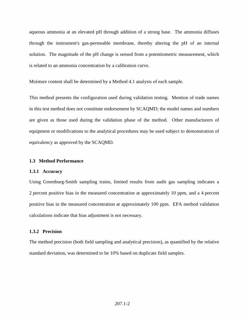
aqueous ammonia at an elevated pH through addition of a strong base. The ammonia diffuses
through the instrument's gas-permeable membrane, thereby altering the pH of an internal
solution. The magnitude of the pH change is sensed from a potentiometric measurement, which
is related to an ammonia concentration by a calibration curve.
Moisture content shall be determined by a Method 4.1 analysis of each sample.
This method presents the configuration used during validation testing. Mention of trade names
in this test method does not constitute endorsement by SCAQMD; the model names and numbers
are given as those used during the validation phase of the method. Other manufacturers of
equipment or modifications to the analytical procedures may be used subject to demonstration of
equivalency as approved by the SCAQMD.
1.3 Method Performance
1.3.1 Accuracy
Using Greenburg-Smith sampling trains, limited results from audit gas sampling indicates a
2 percent positive bias in the measured concentration at approximately 10 ppm, and a 4 percent
positive bias in the measured concentration at approximately 100 ppm. EPA method validation
calculations indicate that bias adjustment is not necessary.
1.3.2 Precision
The method precision (both field sampling and analytical precision), as quantified by the relative
standard deviation, was determined to be 10% based on duplicate field samples.
207.1-3
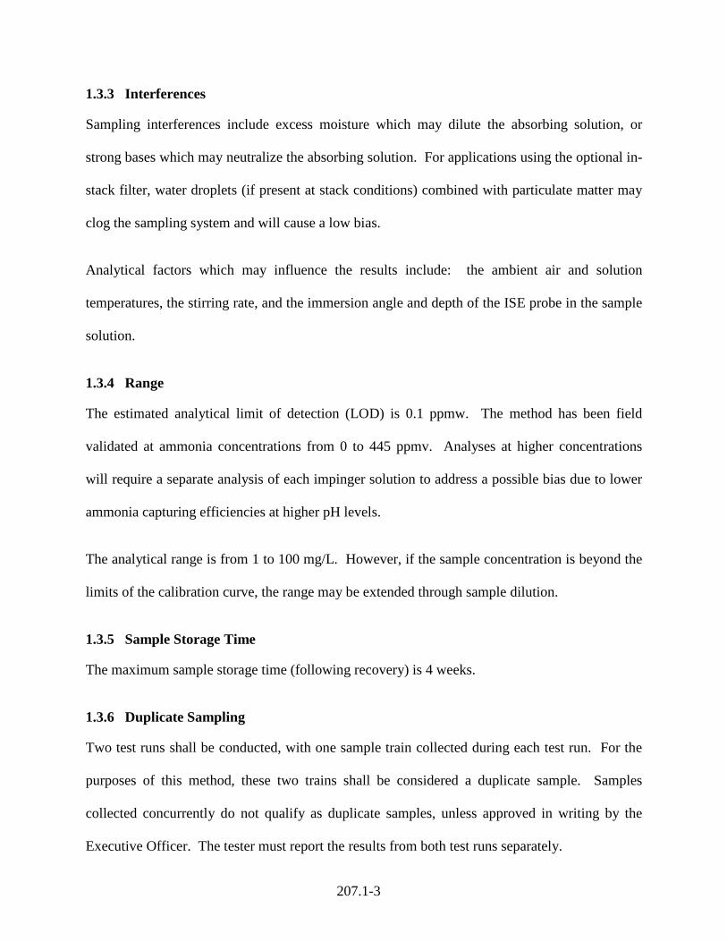
1.3.3 Interferences
Sampling interferences include excess moisture which may dilute the absorbing solution, or
strong bases which may neutralize the absorbing solution. For applications using the optional in-
stack filter, water droplets (if present at stack conditions) combined with particulate matter may
clog the sampling system and will cause a low bias.
Analytical factors which may influence the results include: the ambient air and solution
temperatures, the stirring rate, and the immersion angle and depth of the ISE probe in the sample
solution.
1.3.4 Range
The estimated analytical limit of detection (LOD) is 0.1 ppmw. The method has been field
validated at ammonia concentrations from 0 to 445 ppmv. Analyses at higher concentrations
will require a separate analysis of each impinger solution to address a possible bias due to lower
ammonia capturing efficiencies at higher pH levels.
The analytical range is from 1 to 100 mg/L. However, if the sample concentration is beyond the
limits of the calibration curve, the range may be extended through sample dilution.
1.3.5 Sample Storage Time
The maximum sample storage time (following recovery) is 4 weeks.
1.3.6 Duplicate Sampling
Two test runs shall be conducted, with one sample train collected during each test run. For the
purposes of this method, these two trains shall be considered a duplicate sample. Samples
collected concurrently do not qualify as duplicate samples, unless approved in writing by the
Executive Officer. The tester must report the results from both test runs separately.
207.1-4
METHOD 207.1
DETERMINATION OF AMMONIA EMISSIONS FROM STATIONARY SOURCES
Section 2 of 5 2.0 Sampling Preparation
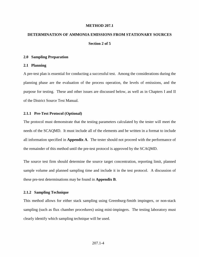
2.1 Planning
A pre-test plan is essential for conducting a successful test. Among the considerations during the
planning phase are the evaluation of the process operation, the levels of emissions, and the
purpose for testing. These and other issues are discussed below, as well as in Chapters I and II
of the District Source Test Manual.
2.1.1 Pre-Test Protocol (Optional)
The protocol must demonstrate that the testing parameters calculated by the tester will meet the
needs of the SCAQMD. It must include all of the elements and be written in a format to include
all information specified in Appendix A. The tester should not proceed with the performance of
the remainder of this method until the pre-test protocol is approved by the SCAQMD.
The source test firm should determine the source target concentration, reporting limit, planned
sample volume and planned sampling time and include it in the test protocol. A discussion of
these pre-test determinations may be found in Appendix B.
2.1.2 Sampling Technique
This method allows for either stack sampling using Greenburg-Smith impingers, or non-stack
sampling (such as flux chamber procedures) using mini-impingers. The testing laboratory must
clearly identify which sampling technique will be used.
207.1-5
2.1.3 Field Blank Trains
A minimum of one blank sampling train shall be analyzed per test set, but no less than one blank
train per day. The blank trains must accompany the sampling trains to the test site, and shall be
assembled and recovered in the exact manner as the sampling trains. A separate analysis of each
train must be performed and reported; however, these results are presented for quality assurance
purposes only, and shall not be used to adjust the data of the emission sample trains.
2.1.4 Fixed Gases Measurement
For stack samples, emission limits for ammonia are generally normalized to a percent level of
oxygen. Additionally, measurements of oxygen, carbon dioxide, and carbon monoxide are
required for molecular weight corrections in flow calculations. Sampling and analysis for these
gases shall be in accordance with SCAQMD Methods 10.1 or 100.1.
2.2. Equipment
2.2.1 Greenburg-Smith Impinger Train
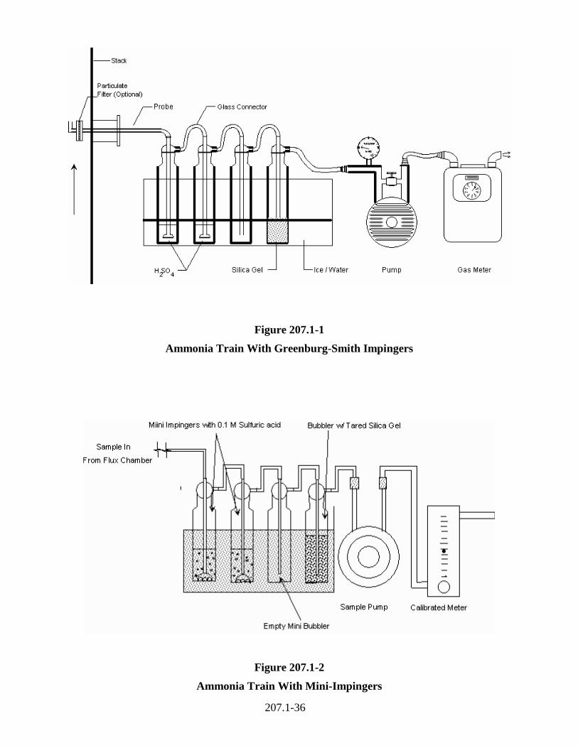
A schematic of the sampling train with the Greenburg-Smith impingers is shown in Figure
207.1-1. This schematic shows the impinger train affixed to the probe. If a flexible connection
between the probe and impingers is desired, use an inert tubing that can withstand the heat at the
probe connection. The sampling train consists of the components below.
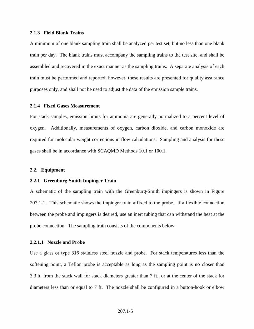
2.2.1.1 Nozzle and Probe
Use a glass or type 316 stainless steel nozzle and probe. For stack temperatures less than the
softening point, a Teflon probe is acceptable as long as the sampling point is no closer than
3.3 ft. from the stack wall for stack diameters greater than 7 ft., or at the center of the stack for
diameters less than or equal to 7 ft. The nozzle shall be configured in a button-hook or elbow
207.1-6
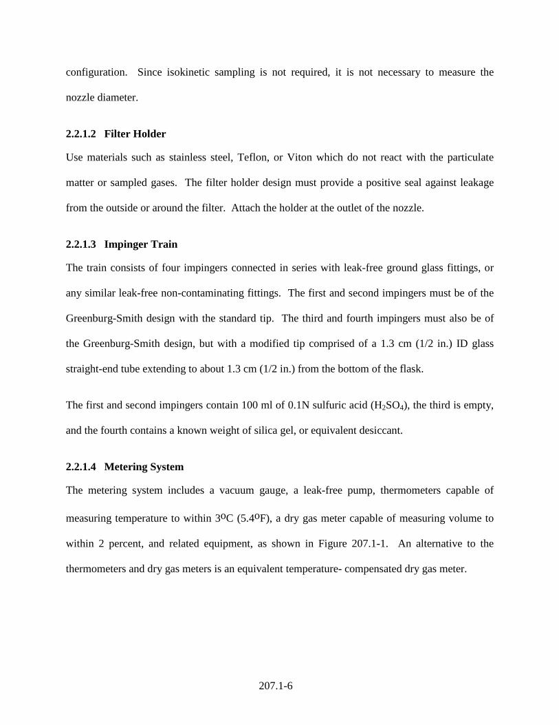
configuration. Since isokinetic sampling is not required, it is not necessary to measure the
nozzle diameter.
2.2.1.2 Filter Holder
Use materials such as stainless steel, Teflon, or Viton which do not react with the particulate
matter or sampled gases. The filter holder design must provide a positive seal against leakage
from the outside or around the filter. Attach the holder at the outlet of the nozzle.
2.2.1.3 Impinger Train
The train consists of four impingers connected in series with leak-free ground glass fittings, or
any similar leak-free non-contaminating fittings. The first and second impingers must be of the
Greenburg-Smith design with the standard tip. The third and fourth impingers must also be of
the Greenburg-Smith design, but with a modified tip comprised of a 1.3 cm (1/2 in.) ID glass
straight-end tube extending to about 1.3 cm (1/2 in.) from the bottom of the flask.
The first and second impingers contain 100 ml of 0.1N sulfuric acid (H2SO4), the third is empty,
and the fourth contains a known weight of silica gel, or equivalent desiccant.
2.2.1.4 Metering System
The metering system includes a vacuum gauge, a leak-free pump, thermometers capable of
measuring temperature to within 3oC (5.4oF), a dry gas meter capable of measuring volume to
within 2 percent, and related equipment, as shown in Figure 207.1-1. An alternative to the
thermometers and dry gas meters is an equivalent temperature- compensated dry gas meter.
207.1-7
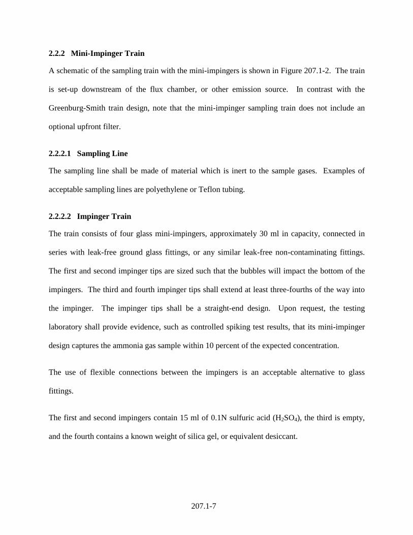
2.2.2 Mini-Impinger Train
A schematic of the sampling train with the mini-impingers is shown in Figure 207.1-2. The train
is set-up downstream of the flux chamber, or other emission source. In contrast with the
Greenburg-Smith train design, note that the mini-impinger sampling train does not include an
optional upfront filter.
2.2.2.1 Sampling Line
The sampling line shall be made of material which is inert to the sample gases. Examples of
acceptable sampling lines are polyethylene or Teflon tubing.
2.2.2.2 Impinger Train
The train consists of four glass mini-impingers, approximately 30 ml in capacity, connected in
series with leak-free ground glass fittings, or any similar leak-free non-contaminating fittings.
The first and second impinger tips are sized such that the bubbles will impact the bottom of the
impingers. The third and fourth impinger tips shall extend at least three-fourths of the way into
the impinger. The impinger tips shall be a straight-end design. Upon request, the testing
laboratory shall provide evidence, such as controlled spiking test results, that its mini-impinger
design captures the ammonia gas sample within 10 percent of the expected concentration.
The use of flexible connections between the impingers is an acceptable alternative to glass
fittings.
The first and second impingers contain 15 ml of 0.1N sulfuric acid (H2SO4), the third is empty,
and the fourth contains a known weight of silica gel, or equivalent desiccant.
207.1-8
2.2.2.3 Metering System
The metering system consists of a leak-free pump, a calibrated flow meter capable of measuring
volume to within 2 percent, and related equipment, as shown in Figure 207.1-2.
2.3 Sampling Reagents
2.3.1 Filters
The in-stack filter shall be constructed from sintered metal. Alternately, glass or quartz fiber
filters without organic binder may be used.
2.3.2 Silica Gel
Indicating-type, 6 to 16 mesh. Use new silica gel as received. If previously used, dry at 175oC
(350oF) for 2 hours. Other desiccants may be used, subject to the approval of the Executive
Officer.
2.3.3 Water
Deionized or distilled to conform to ASTM specifications D-1193-99, Type 3. Water shall be
blank-checked for ammonium ion. The resistivity should be 15 megaohms-cm or higher.
2.3.4 0.1 N Sulfuric Acid Solution
Dilute 2.8 ml of concentrated sulfuric acid (18M) to 1 liter with deionized water to form 0.1 N
sulfuric acid. Alternately, obtain by purchase of reagent grade 0.1N sulfuric acid. Reserve
200 ml as a reagent blank if Greenburg-Smith impinger trains are analyzed (see Section 4.1.1), or
30 ml if mini-impinger trains are analyzed (see Section 4.1.2).
2.3.5 Other Supplies
Crushed ice, or dry ice pellets.
207.1-9
2.4 Sample Train Assembly
During the preparation and assembly, keep all openings covered when contamination can occur
until just prior to assembly. All equipment, including balances, temperature gages, glassware,
and safety equipment should be checked for readiness before proceeding.
2.4.1 Greenburg-Smith Train Assembly
2.4.1.1 Probe and Nozzle
Prepare probe and sampling nozzles for use. Thoroughly clean each component with soap and
water followed by a minimum of three rinses with deionized water. Cap or seal open ends to
prevent contamination prior to sampling.
2.4.1.2 Filter and Filter Holder
For glass or quartz filters, check filters visually against light for irregularities, flaws, or pinhole
leaks. Using tweezers or clean disposable surgical gloves, place a filter in the filter holder. Be
sure that the filter is properly centered and the gasket properly placed to prevent the sample gas
stream from circumventing the filter. Check the filter for tears after assembly is completed.
2.4.1.3 Impinger Train
Assemble the impingers in the tray. Load each of the first two impingers with absorbing
solution. Greenburg-Smith impingers shall contain exactly 100 ml of absorbing solution. Leave
the third impinger empty. Load the last impinger with approximately 200 to 300 grams of silica
gel. If moisture content is to be performed gravimetrically, weigh each impinger plus contents to
the nearest 0.1 g and record the weights.
207.1-10
2.4.2 Mini-Impingers Train Assembly
2.4.2.1 Sampling Line
Acquire a clean or unused sampling line. Connection of the sampling line to the mini-impinger
train may be accomplished either with compression fittings, or by mating the ends with an inert
plastic sleeve.
2.4.2.2 Mini-Impinger Train
Place mini-impingers in the sampling holder. Load each of the first two mini-impingers with
exactly 15 ml absorbing solution. The third impinger is empty. Load the fourth impinger with
approximately 30 to 45 grams of silica gel or equivalent desiccant. If moisture content is to be
performed gravimetrically, weigh each impinger plus contents to the nearest 0.1 g and record the
weights.
207.1-11
METHOD 207.1
DETERMINATION OF AMMONIA EMISSIONS FROM STATIONARY SOURCES
Section 3 of 5 3.0 Field Procedures
3.1 Sampling With Greenburg-Smith Impinger Train
Stack sampling using the Greenburg-Smith style impinger train shall apply the procedures
below.
3.1.1 Calibrations
Follow the calibration procedures and maintenance schedule in Chapter III of the SCAQMD
Source Test Manual. Calibration results shall be submitted with the final test report.
3.1.2 Pre-Test Determinations
If the sampling location is less than eight diameters downstream, and two diameters upstream
from flow disturbances that could alter the ammonia concentration, then the presence of a
stratified concentration distribution in the stack shall be assessed using a pollutant (not diluent)
gas by applying the procedure described in Chapter X, Section 13 of the SCAQMD Source Test
Manual. For stratified concentration distributions in the exhaust stack, traverse sampling is
required per paragraph 2.6 of SCAQMD Method 100.1. Optionally, the tester may presume
stratified conditions and conduct traverse sampling without performing the Chapter X,
Section 13 procedure. If stratified conditions are absent, the sampling point should be either near
the centroid of the stack's cross section, or at a point no closer than 1.00 m (3.3 ft) to the stack's
inner wall.
207.1-12
Sampling should begin and end only when the process has been operating for a sufficient length
of time and steady operations can be assured. A steady state is defined as operating at constant
operating temperature, feed rate, fuel rate, product application, or throughput rate, etc., and that
the production rate is steady throughout the process. For batch or cyclic processes, the sampling
period must encompass at least one complete cycle or batch. The sampling period must also
begin and end at the same point in the cycle so that portions of the cycle are not over or under-
represented.
3.1.3 Field Train Assembly
Connect the nozzle, probe, and filter to the first impinger as shown in Figure 207.1-1. Orient the
nozzle so that the opening will be pointing downstream (directed away from on-coming flow). If
traverse sampling is necessary, mark the probe to indicate the sampling location within the stack.
Ensure that the probe and filter system (if applicable) are properly installed and operational.
Probe assemblies with in-stack filters may be connected to the first impinger of the ammonia
train using polyethylene tubing. Connect the pump and meter to the outlet of the fourth impinger
on the ammonia train. Visually inspect the impingers and other connecting glassware for
damage which may have occurred during transport. Pour water in the impinger tray to a height
above the impinger solution level. Place crushed ice or dry ice pellets around the impingers. If a
determination for ammonia mass emissions is required, assemble the velocity measurement
system per SCAQMD Methods 2.1 or 2.3, and prepare the gas sampling equipment per
SCAQMD Methods 10.1 or 100.1.
3.1.4 Pre-Test Leak Check
Leak check the train at the sampling site by plugging the nozzle and drawing a 380 mm (15 in.)
Hg vacuum. A lesser vacuum may be used if it is not exceeded during the test. The probe may
207.1-13
be leak checked separately at a pressure equal to the stack pressure minus 25 mm (1 in.) Hg. A
leakage rate in excess of either 4 percent of the average sampling rate or 0.00057 m3/min
(0.02 cfm), is unacceptable.
Start the pump with the bypass valve fully open and the coarse adjust valve completely closed.
Partially open the coarse adjust valve and slowly close the bypass valve until the desired vacuum
is reached. Do not reverse direction of bypass valve; this will cause the impinger solution to
back up into the probe. If the desired vacuum is exceeded, either leak check at this higher
vacuum or end the leak check as shown below and start over. When the leak check is completed,
slowly remove the plug from the inlet to the probe, and then turn off the vacuum pump. This
prevents the impinger solution from being forced backward into the filter holder, and silica gel
from being entrained into the third impinger.
Perform a leak check of the Pitot lines in accordance with District Method 2.1, Section 2.2.1, if
exhaust flow velocity will be measured.
3.1.5 Sampling Operation
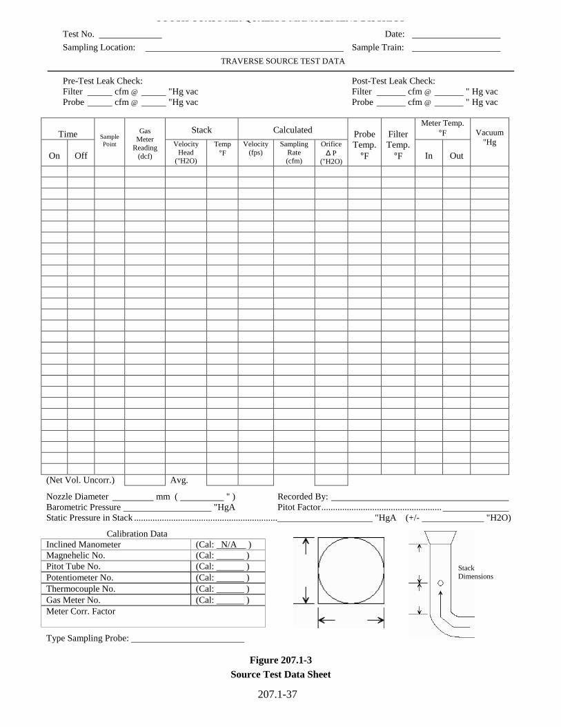
For each run, record the required data on the data sheet shown in Figure 207.1-3. Be sure to
record the initial dry gas meter reading. Record the dry gas meter readings at the beginning and
end of each sampling time increment (no less than 10 minute intervals), when changes in flow
rates are made, before and after each leak check, and when sampling is halted. Record other data
required by the sheet in Figure 207.1-3 at least once for each sample point during each time
increment. Note that data entry under the Probe and Filter Temperature data columns in Figure
207.1-3 is not required, nor is a measurement of the nozzle diameter. The Stack Velocity Heads
and Temperatures shall be recorded per Method 1.1 if a determination of ammonia mass
207.1-14
emissions is desired. The sampling rate shall be between 0.015 m3/min (0.50 cfm) and 0.030
m3/min (1.0 cfm) during the run.
Clean the portholes prior to the test run to minimize the chance of contamination. To begin
sampling, remove the nozzle cap and verify that the Pitot tube and probe are properly positioned.
When the stack is under significant negative pressure (height of absorbing solution in impinger
stem), take care to close the coarse adjust valve before inserting the probe into the stack to
prevent the impinger solution from backing into the probe. If necessary, the pump may be turned
on with the coarse adjust valve closed. When the probe is in position, block off the openings
around the probe and porthole to prevent flow disturbance and dilution of the gas stream.
For tests which require a mass emission determination, prepare the fixed gas sampling system
(SCAQMD Methods 10.1 or 100.1) and collect stack gas concurrently with the ammonia train.
Utilize the Flue Factor Method in accordance with Section 2, Chapter X of the SCAQMD Source
Test Manual, or optionally perform traverse sampling with simultaneous velocity measurements.
Traverse the stack cross section if stratification is present or suspected. Be careful to avoid
bumping the probe nozzle into the stack walls when sampling near the walls or when removing
or inserting the probe through the portholes. This minimizes the chance of extracting stack
deposits.
During the test run, periodically add ice around the outside of the impingers. Also, periodically
check the level and zero of the manometer. Note and investigate any changes in stack
temperature or velocity pressure over those measured during previous tests or traverses.
Changes can mean failure of sampling equipment or a change in process.
207.1-15
If the pressure drop of the filter becomes too high, making sampling difficult to maintain, the
filter may be replaced during a sample run. Use another complete filter assembly rather than
attempting to change the filter itself.
If a component change (e.g. filter assembly or impinger) becomes necessary during the sampling
run, conduct a leak check immediately before the change is made. Use the pretest leak check
procedure, but use a vacuum equal to or greater than the maximum value recorded up to that
point in the test. If the leakage rate is not greater than either 0.00057 m3/min (0.02 cfm) or 4
percent of the average sampling rate, the results are acceptable and no correction has to be
applied to the total volume of dry gas metered. However, if the leakage rate exceeds either of
these limits, the tester must either record the leakage rate and correct the sample volume as
shown in Chapter X, Section 7, or void the sampling run immediately after component change.
At the end of the sample run, turn off the coarse adjust valve, remove the probe and nozzle from
the stack, turn off the pump, record the final dry gas meter reading, and conduct a post test leak
check, as outlined in 3.1.6. Also, leak check Pitot lines, if used, as described in Method 2.1. The
lines must pass this leak check to validate the velocity head data.
3.1.6 Post-Test Procedures
A leak check is mandatory at the conclusion of each sampling run. Allow the probe to cool.
When the probe can be safely handled, follow the procedures outlined in Section 3.1.4 at a
vacuum equal to or greater than the maximum value reached during the sampling run. If the
leakage rate is not greater than either 0.00057 m3/min (0.02 cfm) or 4 percent of the average
sampling rate, the results are acceptable and no correction has to be applied to the total volume

207.1-16
of dry gas metered. However, if the leakage rate exceeds either of these limits, the tester must
void the sampling run, or adjust the sample volume as discussed in Chapter X, Section 7.
Wipe off all external particulate matter near the tip of the probe nozzle and place a cap over it to
prevent contamination. Do not cap off the probe tip tightly while the sampling train is cooling
down. This would create a vacuum in the probe, drawing absorbing solution from the impingers
into the probe.
Before moving the sample train to the clean-up site, remove the probe from the sample train and
cap the open outlets of the probe. Be careful not to lose any condensate that might be present.
Cap the inlet to the impinger train. Remove the connecting tubing after the last impinger and cap
the last impinger. If a flexible line is used between the probe and first impinger, disconnect the
flexible line and gently allow any condensed water or liquid drain into the impingers. Cap off
the open inlet and outlet of the flexible line and impinger train openings. Either ground glass
stoppers, plastic caps, or Parafilm laboratory film (or equivalent) may be used to close these
openings.
Transfer the probe and impinger assembly to the clean-up area. This area should be clean and
protected from the wind to reduce chances of contaminating or losing the sample. It is strongly
recommended that sample recovery be performed in a controlled laboratory environment.
3.2 Mini-Impinger Train
3.2.1 Calibrations
Follow the calibration procedures and maintenance schedule in Chapter III of the SCAQMD
Source Test Manual. Calibration results shall be submitted with the final test report.
207.1-17
3.2.2 Pre-Test Determinations
For non-stack sampling or area source testing, issues such as stratification or steady state
operations shall be addressed on a case-by-case basis. It is strongly recommended that a protocol
be submitted for the District's written approval. For example, compost pile testing should
address parameters such as the age of the pile tested, the sampling locations of the flux chamber
with respect to the height of the pile, diurnal changes in the emission profile, emission
calculation procedures, and other considerations which may affect the representation of the
source.
3.2.3 Field Train Assembly
Attach tubing from the connection point of the flux chamber (or other sampling source) to the
first impinger. Attach the pump and metering system as shown in Figure 207-2. If a rotameter is
used, make sure that the rotameter is vertically upright. Visually inspect the impingers and other
connecting glassware for damage which may have occurred during transport. Place crushed ice
or dry ice pellets around the impingers. Pour water in the impinger tray to a height above the
impinger solution level.
3.2.4 Pre-Test Leak Check
With the impinger train fully assembled, set the pump to the desired sampling rate. Plug the air
flow to the impinger train and observe the meter reading. The leak check is considered
successful if the meter indicates a flow rate less than 4 percent of the average sampling rate.
3.2.5 Sampling Operation
Set the pump to the desired sampling rate, and record the starting time. Periodically inspect and
adjust the sampling rate to assure constant sampling. Also check the amount of ice to maintain
207.1-18
the impinger bath temperature. Should it become necessary to change components during
sampling, leak check the train per paragraph 3.2.4 prior to, and after changing the components.
Record the leak check results and the replaced component on field data sheets.
3.2.6 Post-Test Procedures
Following sampling, perform a post-test leak check per Paragraph 3.2.4, and record the results.
Disconnect the train assembly, and cap or clamp the tubing at the impinger inlet and outlet to
prevent contamination.
207.1-19
METHOD 207.1
DETERMINATION OF AMMONIA EMISSIONS FROM STATIONARY SOURCES
Section 4 of 5 4.0 Laboratory Procedures
4.1 Sample Recovery
The sample shall be recovered within 7 calendar days, and must be performed in an area
protected from the wind, and free from dust and ammonia. The procedures for recovering the
Greenburg-Smith and mini-impinger trains are described in separate sections below.
4.1.1 Greenburg-Smith Impinger Train
Inspect the train for general condition. Note if the silica gel is completely expended, and
whether the train and its components are sealed. Observe if the impinger contents are clear and
odorless, and record any other condition that may be reflected in the analysis. Carefully
disconnect the probe, filter holder and the impingers. Remove the in-stack filter, and record its
condition. Place and seal the filter in a Petri dish, and label the container to clearly identify it.
Weigh each impinger and its contents to the nearest 0.1 gram, and record these weights. Check
and record the pH of each impinger solution; if any of the impinger solutions have a pH greater
than 2, then invalidate the test results.
Transfer the impinger catch to a 500 ml graduated cylinder (or a 1000 ml cylinder, if necessary).
Rinse the inside of the probe, the impingers (except for the silica gel impinger), and all
connecting glassware into the graduated cylinder with deionized (DI) water. Repeat the rinse at
least two additional times, making sure to contact all interior surfaces with each rinse. Dilute the
sample to 500 ml with DI water (or 1000 ml, if necessary). Fasten a stopper on the cylinder and
207.1-20
mix the contents well. Transfer the sample to a container and seal it securely. Label the
container to clearly identify it.
Take 200 ml of the reagent blank (see Section 2.3.4), and dilute it to the sample volume with DI
water. Mix the solution well, then transfer the blank to a container. Securely seal the container,
and label it as a method blank.
Following the recovery, store the samples and method blank in a refrigerator for later analysis.
The refrigerator temperature shall be maintained between 35°F and 45°F.
4.1.2 Mini-Impinger Train
Inspect the train for general condition. Note if the silica gel is completely expended, and if the
train and its components are sealed. Observe if the impinger contents are clear and odorless, and
record any other condition that may be reflected in the analysis. Carefully disconnect the probe
and the impingers. Weigh each impinger plus contents to the nearest 0.1 gram and record these
weights. Check and record the pH of each impinger solution; if any of the impinger solutions
have a pH greater than 2, then invalidate the test results.
Transfer the impinger catch to a 100 ml graduated cylinder (or a 200 ml cylinder, if necessary).
Rinse the inside of the probe, the impingers (except for the silica gel impinger), and all
connecting glassware into the graduated cylinder with deionized water. Repeat the rinse at least
two additional times, making sure to contact all interior surfaces with each rinse. Dilute the
sample to 75 ml with DI water. Fasten a stopper on the cylinder and mix the contents well.
Transfer the sample to a container and seal it securely. Label the container to clearly identify it.
207.1-21
Take 30 ml of the reagent blank (see Section 2.3.4), and dilute it to the sample volume with DI
water. Mix the solution well, then transfer the blank to a container. Securely seal the container,
and label it as a method blank.
Following recovery, store the samples and method blank in a refrigerator for later analysis. The
refrigerator temperature shall be maintained between 35°F and 45°F.
4.2 Analysis
4.2.1 Equipment
a. Electrometer (pH meter) with expanded millivolt scale capable of 0.1 mV resolution
between -700 mV to +700 mV.
b. Orion Ammonia Electrode (electrode), Model 95-12 or equivalent. Cat. No.951201,
9512NB or equivalent.
c. Graduated cylinder, various sizes as needed.
d. Beakers, 150 ml.
e. Volumetric Pipettes, Class A borosilicate glass, various sizes as needed.
f. Volumetric Flasks, Class A, various sizes as needed.
g. Balance, analytical, accurate to 0.1 g.
h. Magnetic stirrer, thermally insulated, and Teflon coated stirring bar.
i. Micropipette, 0.1 ml to 1 ml.
4.2.2 Reagents
a. Ionic Strength Adjustor (ISA), ammonia pH adjusting solution (Orion catalog # 951211, or
equivalent).
b. Ammonia standard solution, 0.1M NH4Cl or 1400 mg/L as N (Orion catalog # 951006, or
equivalent).
207.1-22
c. Deionized (DI) or distilled water to conform to ASTM specifications D-1193-99, Type 3.
Water shall be blank-checked for ammonium ion.
d. Ammonia as Nitrogen standard, 1000 mg/L (Orion catalog #951007, or equivalent).
e. Calibration Verification solution. Pipette 10 ml of 0.1M NH4Cl standard solution (Orion
catalog #951006, or equivalent) into a 500 ml volumetric flask and dilute to the mark with
0.04 N H2SO4. The Calibration Verification concentration is 0.002 M NH4Cl, or 28 mg
NH3-N/L. For highly concentrated or dilute ammonia samples, the Calibration Verification
solution may be adjusted accordingly to reflect the concentrations being analyzed. The
Calibration Verification solution must be prepared prior to each analysis.
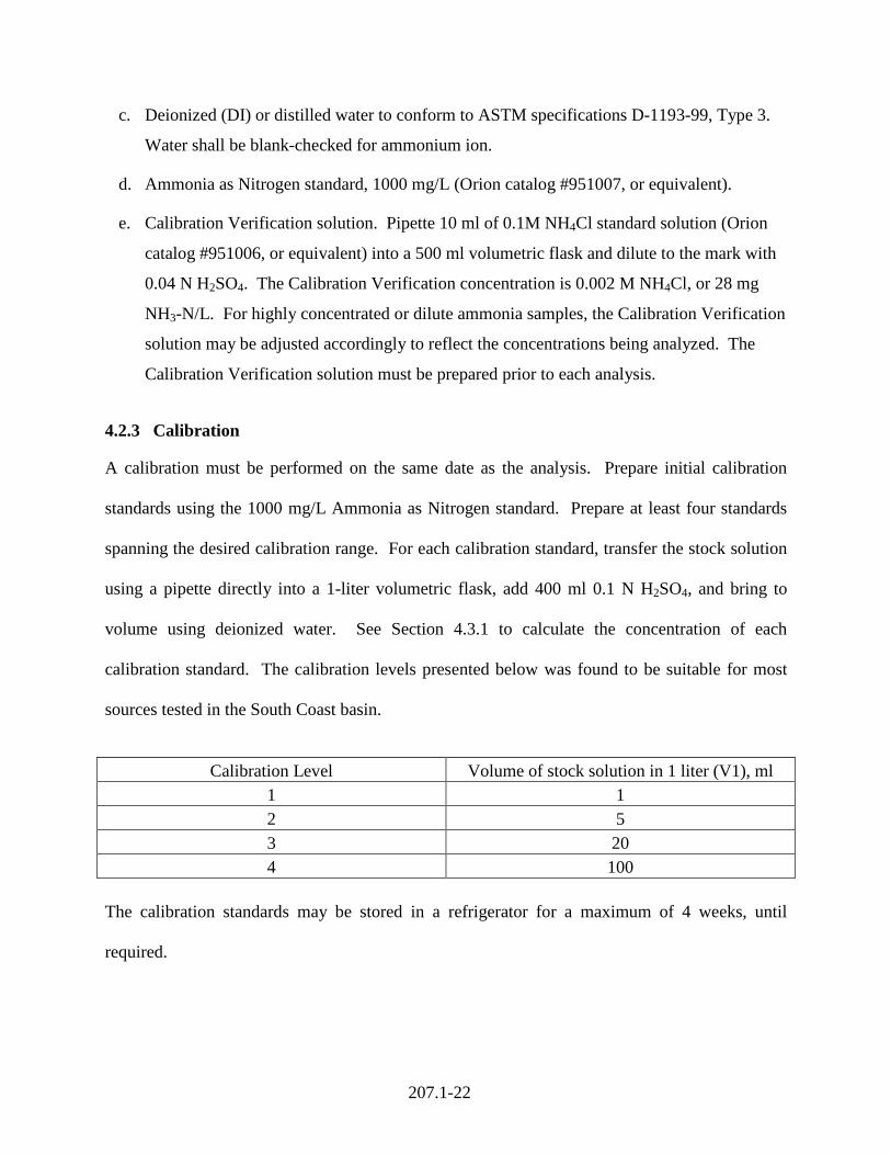
4.2.3 Calibration
A calibration must be performed on the same date as the analysis. Prepare initial calibration
standards using the 1000 mg/L Ammonia as Nitrogen standard. Prepare at least four standards
spanning the desired calibration range. For each calibration standard, transfer the stock solution
using a pipette directly into a 1-liter volumetric flask, add 400 ml 0.1 N H2SO4, and bring to
volume using deionized water. See Section 4.3.1 to calculate the concentration of each
calibration standard. The calibration levels presented below was found to be suitable for most
sources tested in the South Coast basin.
Calibration Level Volume of stock solution in 1 liter (V1), ml 1 1 2 5 3 20 4 100
The calibration standards may be stored in a refrigerator for a maximum of 4 weeks, until
required.
207.1-23
Place 100 ml of each standard solution into clean 150 ml beakers. Immerse the electrode into the
standard of lowest concentration, and add 2 ml of ISA while mixing. The solution must turn and
remain blue, indicating an alkaline mixture. Keep the electrode in the solution until a stable
reading is attained. Record the solution color, solution temperature, and electrode reading. The
procedures in Section 4.2.4 shall be applied to insure accurate electrode measurements.
Repeat the procedure with the remaining standards, progressing from lowest to highest
concentration. Calculate the concentration of ammonia (mg NH3-N/L) in the standards per
Section 4.3.1. Plot the logarithm of the concentration of ammonia (mg NH3-N/L) versus the
electrode potential developed in the standard, and determine the calibration regression line per
Section 4.3.2.
4.2.4 Analytical Procedure
The electrode is sensitive to measurement conditions, and should be carefully handled and
maintained to prevent spurious readings. The electrode must be rinsed with DI water and blotted
dry between measurements. To prevent air entrapment on the membrane surface, use an
electrode holder that secures the electrode at a 20 angle from vertical. If bubbles appear on the
sensing membrane, tap the electrode gently to remove them. Samples and standards should be
stirred at a constant rate using a magnetic stirrer. For electrode storage, refer to manufacturer’s
instructions.
When taking measurements, use beakers that minimize the ratio of surface area to volume. Keep
beakers containing standards and samples covered between readings.
207.1-24
4.2.4.1 Greenburg-Smith Impinger Train
Remove the samples and standards from the refrigerator, and allow them to equilibrate to room
temperature. Record the temperature of the room. All analyses must be performed at equivalent
ambient conditions.
Perform the analyses in the following order, which constitutes one batch:
1) Prepare calibration standards according to Section 4.2.3, and establish the calibration
curve. Fit the calibration data to a linear regression per Section 4.3.2.
2) Prepare a matrix spike by transferring 100 ml of sample to a clean 150 ml beaker, and
add 2 ml of the 1000 mg/L Ammonia as Nitrogen Standard. Prepare a second identical
solution for a duplicate analysis.
3) Prepare each sample, DI water blank, and a Calibration Verification Standard by
transferring 100 ml of each solution to separate, clean 150 ml beakers. Prepare a second
identical set of solutions for duplicate analyses.
4) Perform analyses of the duplicate blanks, samples, Calibration Verification Standards,
and matrix spike solutions beginning with the solution having the lowest expected
concentration, followed by analyses of progressively more concentrated solutions.
Immerse the electrode into each solution and add 2 ml ISA while mixing. The solution
must turn blue and remain blue to indicate it is alkaline. Keep the electrode in the
solution until a stable reading is obtained. Record the solution color, the stabilized
potential, and the temperature of the sample solution.
5) An analysis of the duplicate Calibration Verification Standards are to follow every fifth
duplicate sample to confirm the calibration curve is adequate.
207.1-25
6) Analyze no more than ten duplicate samples, one matrix spike (and one matrix spike
duplicate) in a batch. Analyze the duplicate Calibration Verification Standards at the
end of the batch. Refer to Section 4.4 for Quality Control requirements.
7) Convert all the potential readings to ammonia concentrations (as mg NH3-N/L) using the
calibration curve per Section 4.3.3.
4.2.4.2 Mini-Impinger Train
Remove the samples and standards from the refrigerator, and allow them to equilibrate to room
temperature. Record the temperature of the room. All analyses must be performed at equivalent
ambient conditions.
Perform the analyses in the following order, which constitutes one batch:
1) Prepare calibration standards according to Section 4.2.3, and establish the calibration
curve. Fit the calibration data to a linear regression per Section 4.3.2.
2) Prepare each sample, DI water blank, and a Calibration Verification Standard by
transferring 30 ml of each solution to separate, clean 50 ml beakers. Prepare a second
identical set of solutions for duplicate analyses.
3) Perform analyses of the duplicate blanks, samples, and Calibration Verification Standard
solutions beginning with the solution having the lowest expected concentration.
Immerse the electrode into each solution and add 2 ml ISA while mixing. The solution
must turn blue and remain blue to indicate it is alkaline. Keep the electrode in the
solution until a stable reading is obtained. Record the solution color, the stabilized
potential, and the temperature of the sample solution.
207.1-26
4) An analysis of the duplicate Calibration Verification Standards are to follow every fifth
duplicate sample to confirm the calibration curve is adequate.
5) Analyze no more than ten duplicate samples in a batch. Analyze the duplicate
Calibration Verification Standards at the end of the batch. Refer to Section 4.4 for
Quality Control requirements.
6) Convert all the potential readings to ammonia concentrations (as mg NH3-N/L) using the
calibration curve per Section 4.3.3.
4.2.4.3 Sample Dilutions
If the sample is not within the calibration range, the sample must be diluted. Estimate the
solution concentration by diluting a sample aliquot with 0.04 N H2SO4. Note that QC procedures
are not necessary, since the estimation is qualitative. Based on the estimated concentration,
determine the appropriate dilution that would yield a concentration in the middle of the
calibration range. Prepare the sample with the appropriate dilution, and perform the analysis as
specified in Sections 4.2.4.1 or 4.2.4.2, with all applicable QC.
4.3 Calculations
4.3.1 Calibration Standards
mg NH3-N/L = (V1 / 1000) * S1 where:
S1: Concentration of the Ammonia as Nitrogen standard (refer to Section 4.2.3), 1000 mg/L Ammonia as Nitrogen.
V1: volume of the stock solution (ml) to make 1 liter calibration standard (refer to Section 4.2.3).
1000: 1-liter solution (1000 ml).
207.1-27
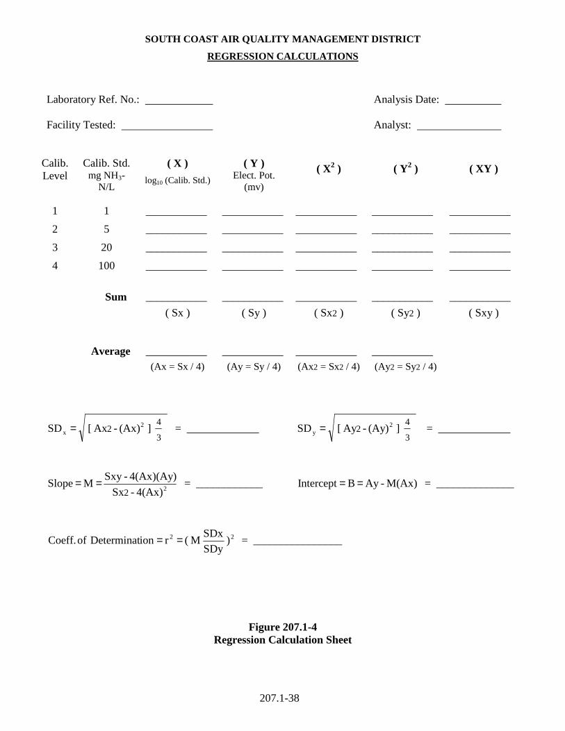
4.3.2 Calibration Regression Line
Determine a standard regression line of calibration standards versus electrode potential (P) in
millivolts (determined in Section 4.2.3) using the relation below. Calculate the regression
parameters using the calculation sheet shown on Figure 207.1-4.
P = M * log (mg of NH3-N/L) + B where:
M = slope
B = intercept
4.3.3 Measured Concentration Of Ammonia
Calculate the measured concentration (C) of ammonia (mg of NH3-N/L) from the electrode
potentials recorded in Sections 4.2.4.1 or 4.2.4.2:
C = 10 (P-B)/M
4.3.4 Average Measured Ammonia Concentration (Cavg)
Cavg = (C1+C2) / 2
where:
C1, C2 = results from duplicate analyses (mg NH3-N/L)
4.3.5 Relative Percent Difference (RPD)
The RPD is determined from duplicate analyses as follows:
RPD = (C1-C2) / Cavg * 100
207.1-28
4.3.6 Relative Percent Accuracy (RPA)
Determine the RPA of the calculated concentration for Calibration Verification:
RPA = (Cavg-28) / 28 * 100 where
28 = theoretical value of the check standard (mg NH3-N/L) (see Section 4.2.2(e))
4.3.7 Matrix Spike Percent Recovery (%R)
%R is calculated as follows:
%R = (Cspike * 0.104-Csample * 0.102) / 2.0 * 100
where:
Cspike = average result of matrix spike analysis (mg NH3-N/L)
Csample = average result from duplicate analyses of unspiked sample (mg NH3-N/L)
4.4 Quality Control
4.4.1 Initial Calibration
Instrument performance parameters (slope and intercept) must be determined and demonstrated
through regression analysis to be acceptable for this method. If any major changes are made to
the system, recalibrate the instrument to verify these parameters and demonstrate the instrument's
acceptability. Determine the slope (M) and intercept (B) if they have not been previously
measured. Track instrument performance against previous test batches by control charting the
slope values.
The slope of the calibration curve (M) shall be in the range of -54 to -60. In addition, the
coefficient of determination (r2) of the calibration curve must be 0.997 or greater (see Figure
207.1-4 for the calculation of r2). If both these linearity criteria are not satisfied, the calibration
207.1-29
is unacceptable. To remedy this, the analyst may elect to check the electrode, prepare fresh
standards, troubleshoot the instrument, or perform routine instrument maintenance prior to
recalibrating the instrument.
4.4.2 Calibration Verification
The relative percent accuracy (RPA) of the Calibration Verification must be 10% or less. If the
initial Calibration Verification check does not satisfy this criteria, prepare a new Calibration
Verification standard and analyze it. If this standard also fails to meet the control limit,
troubleshoot the instrument and perform another Calibration Verification check. If this third
Calibration Verification fails, discard the initial calibration and determine new instrument
performance parameters.
4.4.3 Measurement Stability
Due to the instrument's sensitivity to solution temperature, the calibration solutions, sample
solutions, and Calibration Verification standard temperatures must all be within ± 2°C of one
another. All solution temperatures must be submitted with the laboratory report.
The relative percent difference (RPD) of duplicate measurements of the calibration output and
sample results must be 5% or less. If the RPD exceeds this criteria, troubleshoot the instrument
and prepare fresh standards.
4.4.4 Matrix Spike Recovery
An evaluation of the Matrix Spike Recovery (%R) is performed on a qualitative basis only, and
is intended to provide a symptomatic overview of the analysis. Although there are no criteria for
acceptability of %R, the data is useful for identifying possible errors in the analysis and must be
submitted with the test report.

207.1-30
4.4.5 Temperature Probe
At three month intervals, the probe measuring the solution temperature shall be checked at two
conditions: in chilled ice water (approximately 32°F), and in water at room temperature
(approximately 75°F). Measurements shall be made simultaneously with a reference temperature
sensing instrument. The reference instrument shall be calibrated per the Chapter III procedures
of the SCAQMD Source Test Manual. The difference between the temperature probe and
reference instrument shall agree within 1.5 percent of the absolute reference temperature
(degrees Rankine).
207.1-31
METHOD 207.1
DETERMINATION OF AMMONIA EMISSIONS FROM STATIONARY SOURCES
Section 5 of 5 5.0 Emissions Reporting
5.1 Engineering Calculations
Carry out calculations, retaining at least one extra decimal figure beyond that of the acquired
data. Round off figures after the final calculation.
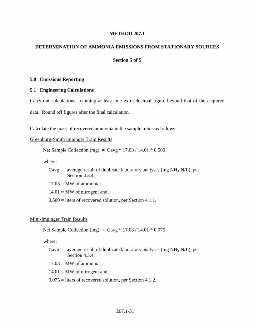
Calculate the mass of recovered ammonia in the sample trains as follows:
Greenburg-Smith Impinger Train Results
Net Sample Collection (mg) = Cavg * 17.03 / 14.01 * 0.500 where:
Cavg = average result of duplicate laboratory analyses (mg NH3-N/L), per Section 4.3.4;
17.03 = MW of ammonia;
14.01 = MW of nitrogen; and,
0.500 = liters of recovered solution, per Section 4.1.1.
Mini-Impinger Train Results
Net Sample Collection (mg) = Cavg * 17.03 / 14.01 * 0.075 where:
Cavg = average result of duplicate laboratory analyses (mg NH3-N/L), per Section 4.3.4;
17.03 = MW of ammonia;
14.01 = MW of nitrogen; and,
0.075 = liters of recovered solution, per Section 4.1.2.

207.1-32
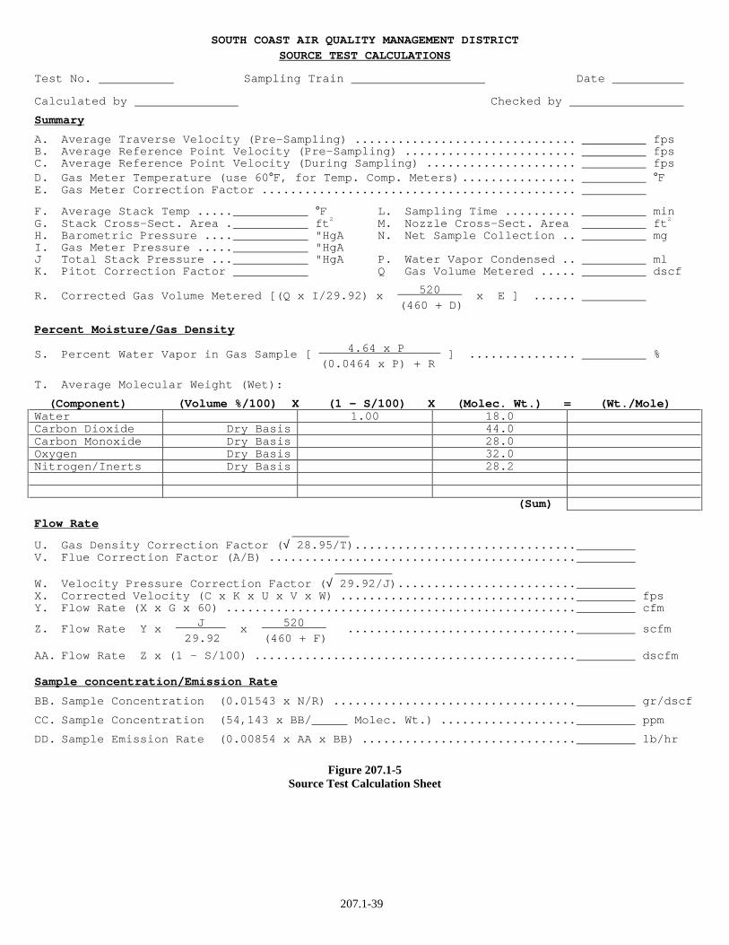
To calculate the ammonia concentration and mass emissions at the stack, a calculation sheet
similar to that shown in Figure 207.1-5 may be used. Other forms of the equations may be used
as long as they give equivalent results.
Results of each duplicate train must be reported separately; the highest valid emission result shall
be used for compliance purposes.
5.2 Report Information
The following information is to be included in the test report:
1. All printouts (as applicable), must be included in the final report and must be clearly
identified as to:
-location/source -range changes
-operator initials -range of measurement
-date/running times -calibrations
-actual test interval -cal gas concentration/cyl. no.
-contaminant/diluent -range of calibration
2. A summary of the Source Test results.
3. A brief process description. Indicate equipment and process operation during testing,
as well as any other information which may influence the final report.
4. A simple schematic diagram of the process, showing the sampling location, with
respect to the upstream and downstream flow disturbances.
5. The sampling and analytical procedures. Be specific about all aspects of sampling
and analysis. Include diagrams of test equipment and methods.
207.1-33
6. Complete raw field data, including production and all operating data indicative of the
testing interval, analyses, and the test results (show all calculations).
7. Complete laboratory and analytical data, including all calibration and QA/QC data. If
spreadsheets are used, an annotated sample calculation shall be provided.
8. Calibration data regarding all sampling and measuring equipment utilized during
testing (see SCAQMD Source Testing Manual, Chapter III).
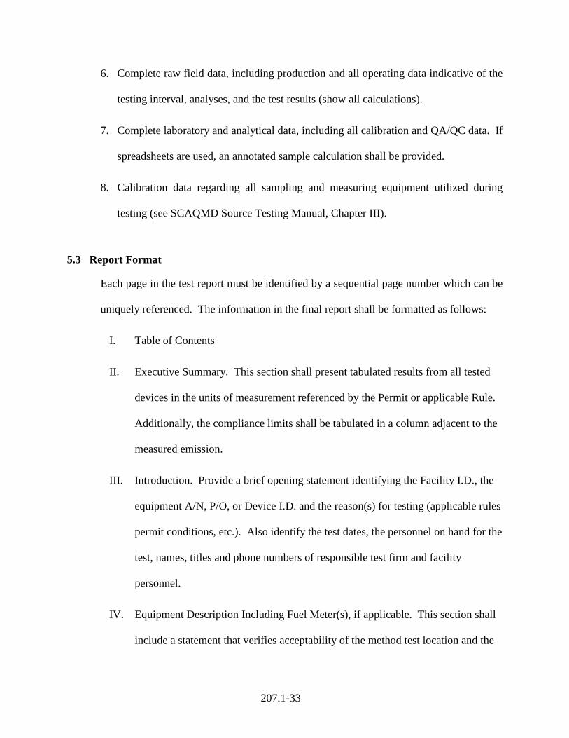
5.3 Report Format
Each page in the test report must be identified by a sequential page number which can be
uniquely referenced. The information in the final report shall be formatted as follows:
I. Table of Contents
II. Executive Summary. This section shall present tabulated results from all tested
devices in the units of measurement referenced by the Permit or applicable Rule.
Additionally, the compliance limits shall be tabulated in a column adjacent to the
measured emission.
III. Introduction. Provide a brief opening statement identifying the Facility I.D., the
equipment A/N, P/O, or Device I.D. and the reason(s) for testing (applicable rules
permit conditions, etc.). Also identify the test dates, the personnel on hand for the
test, names, titles and phone numbers of responsible test firm and facility
personnel.
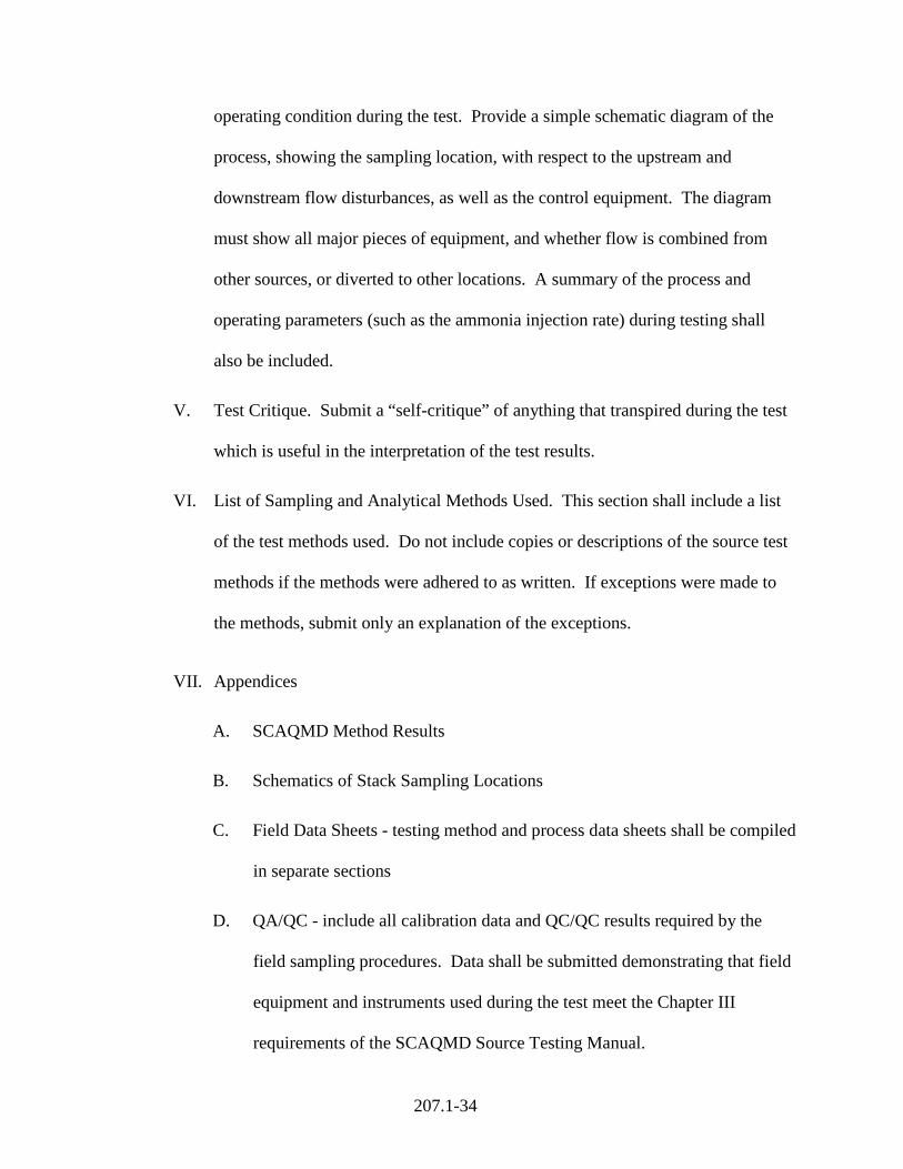
IV. Equipment Description Including Fuel Meter(s), if applicable. This section shall
include a statement that verifies acceptability of the method test location and the
207.1-34
operating condition during the test. Provide a simple schematic diagram of the
process, showing the sampling location, with respect to the upstream and
downstream flow disturbances, as well as the control equipment. The diagram
must show all major pieces of equipment, and whether flow is combined from
other sources, or diverted to other locations. A summary of the process and
operating parameters (such as the ammonia injection rate) during testing shall
also be included.
V. Test Critique. Submit a “self-critique” of anything that transpired during the test
which is useful in the interpretation of the test results.
VI. List of Sampling and Analytical Methods Used. This section shall include a list
of the test methods used. Do not include copies or descriptions of the source test
methods if the methods were adhered to as written. If exceptions were made to
the methods, submit only an explanation of the exceptions.
VII. Appendices
A. SCAQMD Method Results
B. Schematics of Stack Sampling Locations
C. Field Data Sheets - testing method and process data sheets shall be compiled
in separate sections
D. QA/QC - include all calibration data and QC/QC results required by the
field sampling procedures. Data shall be submitted demonstrating that field
equipment and instruments used during the test meet the Chapter III
requirements of the SCAQMD Source Testing Manual.

207.1-35
E. Laboratory Analytical Results, including all raw data including (but not
limited to) solution temperatures, annotated calculations, and analytical
QA/QC data.
F. Calibration Data and Calculations
G. Calibration Gas Certificates
H. Chain of Custody Information (as necessary)
I. Process Operating Data Including Fuel Usage During Test
J. Calculations Using Fuel F-Factor (if necessary)
K. Copy of SCAQMD Permit/ Application
L. Signed “Statement of Non-Conflict as an Independent Laboratory” per
District Rule 304(k)
207.1-36
Figure 207.1-1
Ammonia Train With Greenburg-Smith Impingers
Figure 207.1-2
Ammonia Train With Mini-Impingers
207.1-37
SOUTH COAST AIR QUALITY MANAGEMENT DISTRICT
Test No. Date:
Sampling Location: Sample Train:
TRAVERSE SOURCE TEST DATA
Pre-Test Leak Check: Post-Test Leak Check: Filter cfm @ "Hg vac Filter cfm @ " Hg vac Probe cfm @ "Hg vac Probe cfm @ " Hg vac
Time
Stack
Calculated Meter Temp.
°F
On
Off
Sample Point
Gas
Meter Reading
(dcf)
Velocity Head
("H2O)
Temp °F
Velocity (fps)
Sampling Rate (cfm)
Orifice ∆ P
("H2O)
Probe Temp.
°F
Filter Temp.
°F
In
Out
Vacuum
"Hg
(Net Vol. Uncorr.) Avg.
Nozzle Diameter mm ( " ) Recorded By: Barometric Pressure "HgA Pitot Factor.................................................... Static Pressure in Stack .............................................................. "HgA (+/- "H2O)
Calibration Data Inclined Manometer (Cal: N/A ) Magnehelic No. (Cal: ) Pitot Tube No. (Cal: ) Potentiometer No. (Cal: ) Thermocouple No. (Cal: ) Gas Meter No. (Cal: ) Meter Corr. Factor
Type Sampling Probe:
Figure 207.1-3 Source Test Data Sheet
Stack Dimensions
207.1-38
SOUTH COAST AIR QUALITY MANAGEMENT DISTRICT
REGRESSION CALCULATIONS
Laboratory Ref. No.: Analysis Date: Facility Tested: Analyst:
Calib. Level
Calib. Std. mg NH3-
N/L
( X )
log10 (Calib. Std.)
( Y ) Elect. Pot.
(mv)
( X2 ) ( Y2 ) ( XY )
1 1 ___________ ___________ ___________ ___________ ___________
2 5 ___________ ___________ ___________ ___________ ___________
3 20 ___________ ___________ ___________ ___________ ___________
4 100 ___________ ___________ ___________ ___________ ___________
Sum ___________ ___________ ___________ ___________ ___________ ( Sx ) ( Sy ) ( Sx2 ) ( Sy2 ) ( Sxy ) Average ___________ ___________ ___________ ___________ (Ax = Sx / 4) (Ay = Sy / 4) (Ax2 = Sx2 / 4) (Ay2 = Sy2 / 4)
] (Ax) - Ax [ SD 3
42 2
x = = _____________ ] (Ay) - Ay [ SD 3
42 2
y = = _____________
24(Ax) - Sx
4(Ax)(Ay) -Sxy M Slope
2== = ____________ M(Ax) -Ay B Intercept == = ______________
22 ) SDy
SDx M ( r ion Determinat of Coeff. == = ________________
Figure 207.1-4 Regression Calculation Sheet
207.1-39
SOUTH COAST AIR QUALITY MANAGEMENT DISTRICT SOURCE TEST CALCULATIONS
Test No. Sampling Train Date
Calculated by Checked by
Summary
A. Average Traverse Velocity (Pre-Sampling) ............................... fps B. Average Reference Point Velocity (Pre-Sampling) ........................ fps C. Average Reference Point Velocity (During Sampling) ..................... fps D. Gas Meter Temperature (use 60°F, for Temp. Comp. Meters)................ °F E. Gas Meter Correction Factor ............................................
F. Average Stack Temp ..... °F L. Sampling Time .......... min G. Stack Cross-Sect. Area . ft2 M. Nozzle Cross-Sect. Area ft2 H. Barometric Pressure .... "HgA N. Net Sample Collection .. mg I. Gas Meter Pressure ..... "HgA J Total Stack Pressure ... "HgA P. Water Vapor Condensed .. ml K. Pitot Correction Factor Q Gas Volume Metered ..... dscf
R. Corrected Gas Volume Metered [(Q x I/29.92) x 520 x E ] ...... (460 + D)
Percent Moisture/Gas Density
S. Percent Water Vapor in Gas Sample [ 4.64 x P ] ............... % (0.0464 x P) + R
T. Average Molecular Weight (Wet):
(Component) (Volume %/100) X (1 - S/100) X (Molec. Wt.) = (Wt./Mole) Water 1.00 18.0 Carbon Dioxide Dry Basis 44.0 Carbon Monoxide Dry Basis 28.0 Oxygen Dry Basis 32.0 Nitrogen/Inerts Dry Basis 28.2 (Sum)
Flow Rate
U. Gas Density Correction Factor (√ 28.95/T)............................... V. Flue Correction Factor (A/B) ........................................... W. Velocity Pressure Correction Factor (√ 29.92/J)......................... X. Corrected Velocity (C x K x U x V x W) ................................. fps Y. Flow Rate (X x G x 60) ................................................. cfm
Z. Flow Rate Y x J x 520 ................................ scfm 29.92 (460 + F)
AA. Flow Rate Z x (1 - S/100) ............................................. dscfm
Sample concentration/Emission Rate
BB. Sample Concentration (0.01543 x N/R) .................................. gr/dscf
CC. Sample Concentration (54,143 x BB/ Molec. Wt.) ................... ppm
DD. Sample Emission Rate (0.00854 x AA x BB) .............................. lb/hr
Figure 207.1-5 Source Test Calculation Sheet
A-1
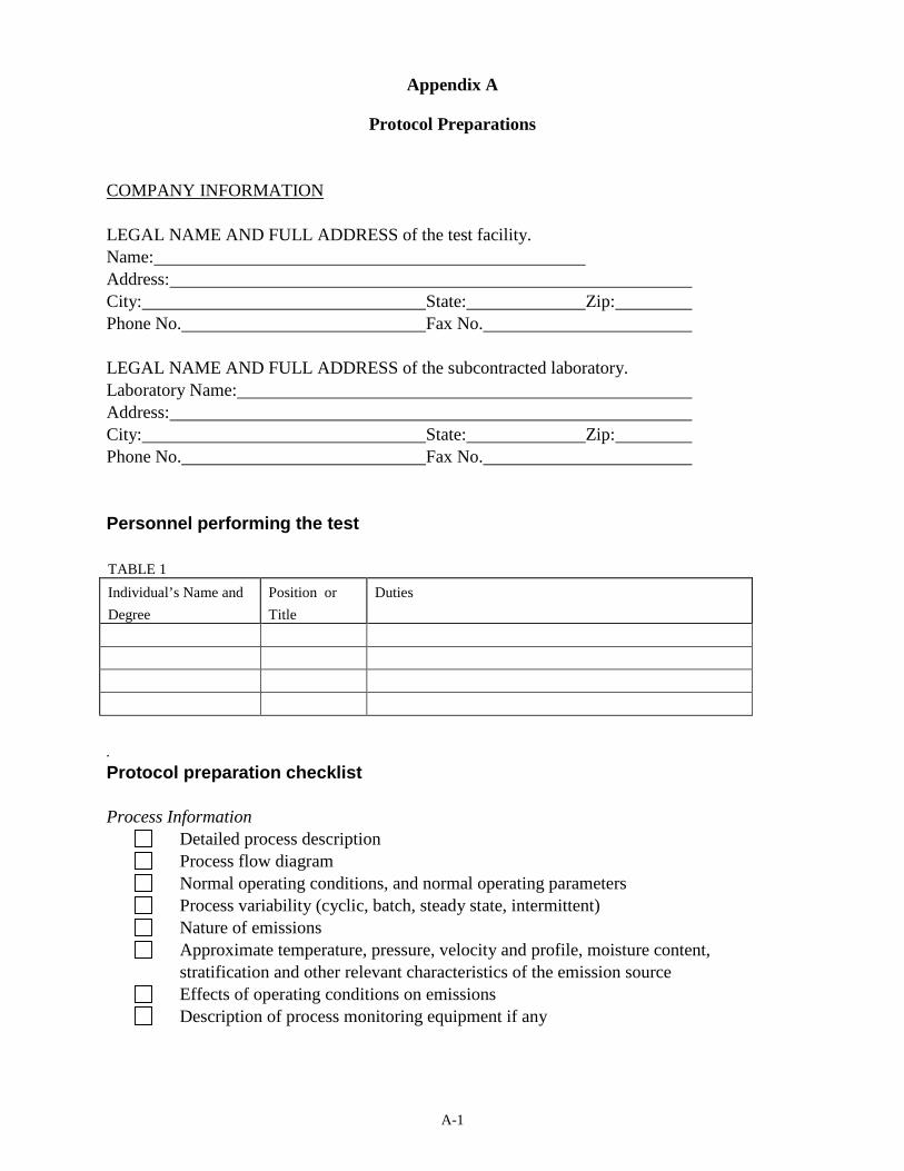
Appendix A
Protocol Preparations
COMPANY INFORMATION LEGAL NAME AND FULL ADDRESS of the test facility. Name: Address: City: State: Zip: Phone No. Fax No. LEGAL NAME AND FULL ADDRESS of the subcontracted laboratory. Laboratory Name: Address: City: State: Zip: Phone No. Fax No. Personnel performing the test TABLE 1
Individual’s Name and
Degree
Position or
Title
Duties
.
Protocol preparation checklist Process Information Detailed process description Process flow diagram Normal operating conditions, and normal operating parameters Process variability (cyclic, batch, steady state, intermittent) Nature of emissions Approximate temperature, pressure, velocity and profile, moisture content,
stratification and other relevant characteristics of the emission source Effects of operating conditions on emissions Description of process monitoring equipment if any
A-2
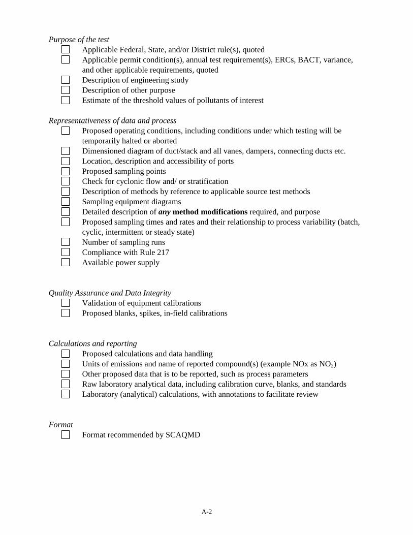
Purpose of the test Applicable Federal, State, and/or District rule(s), quoted Applicable permit condition(s), annual test requirement(s), ERCs, BACT, variance,
and other applicable requirements, quoted Description of engineering study Description of other purpose Estimate of the threshold values of pollutants of interest Representativeness of data and process Proposed operating conditions, including conditions under which testing will be
temporarily halted or aborted Dimensioned diagram of duct/stack and all vanes, dampers, connecting ducts etc. Location, description and accessibility of ports Proposed sampling points Check for cyclonic flow and/ or stratification Description of methods by reference to applicable source test methods Sampling equipment diagrams Detailed description of any method modifications required, and purpose Proposed sampling times and rates and their relationship to process variability (batch,
cyclic, intermittent or steady state) Number of sampling runs Compliance with Rule 217 Available power supply Quality Assurance and Data Integrity Validation of equipment calibrations Proposed blanks, spikes, in-field calibrations Calculations and reporting Proposed calculations and data handling Units of emissions and name of reported compound(s) (example NOx as NO2) Other proposed data that is to be reported, such as process parameters Raw laboratory analytical data, including calibration curve, blanks, and standards Laboratory (analytical) calculations, with annotations to facilitate review Format Format recommended by SCAQMD
B-1
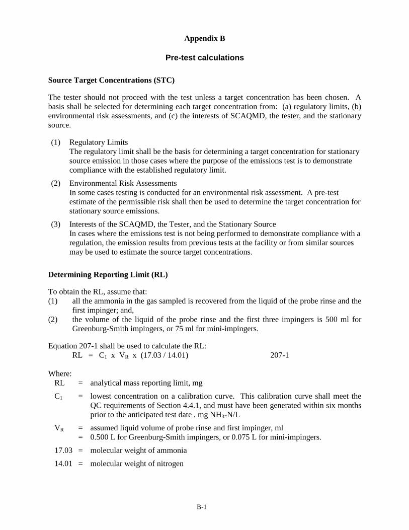
Appendix B
Pre-test calculations
Source Target Concentrations (STC)
The tester should not proceed with the test unless a target concentration has been chosen. A basis shall be selected for determining each target concentration from: (a) regulatory limits, (b) environmental risk assessments, and (c) the interests of SCAQMD, the tester, and the stationary source.
(1) Regulatory Limits The regulatory limit shall be the basis for determining a target concentration for stationary source emission in those cases where the purpose of the emissions test is to demonstrate compliance with the established regulatory limit.
(2) Environmental Risk Assessments In some cases testing is conducted for an environmental risk assessment. A pre-test estimate of the permissible risk shall then be used to determine the target concentration for stationary source emissions.
(3) Interests of the SCAQMD, the Tester, and the Stationary Source In cases where the emissions test is not being performed to demonstrate compliance with a regulation, the emission results from previous tests at the facility or from similar sources may be used to estimate the source target concentrations.
Determining Reporting Limit (RL)
To obtain the RL, assume that: (1) all the ammonia in the gas sampled is recovered from the liquid of the probe rinse and the
first impinger; and, (2) the volume of the liquid of the probe rinse and the first three impingers is 500 ml for
Greenburg-Smith impingers, or 75 ml for mini-impingers.
Equation 207-1 shall be used to calculate the RL: RL = C1 x VR x (17.03 / 14.01) 207-1 Where:
RL = analytical mass reporting limit, mg
C1 = lowest concentration on a calibration curve. This calibration curve shall meet the QC requirements of Section 4.4.1, and must have been generated within six months prior to the anticipated test date , mg NH3-N/L
VR = assumed liquid volume of probe rinse and first impinger, ml = 0.500 L for Greenburg-Smith impingers, or 0.075 L for mini-impingers.
17.03 = molecular weight of ammonia
14.01 = molecular weight of nitrogen
B-2
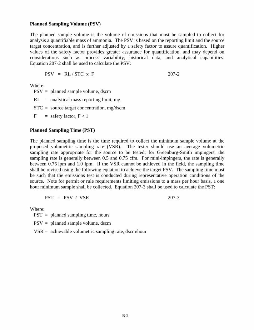
Planned Sampling Volume (PSV)
The planned sample volume is the volume of emissions that must be sampled to collect for analysis a quantifiable mass of ammonia. The PSV is based on the reporting limit and the source target concentration, and is further adjusted by a safety factor to assure quantification. Higher values of the safety factor provides greater assurance for quantification, and may depend on considerations such as process variability, historical data, and analytical capabilities. Equation 207-2 shall be used to calculate the PSV:
PSV = RL / STC x F 207-2 Where:
PSV = planned sample volume, dscm
RL = analytical mass reporting limit, mg
STC = source target concentration, mg/dscm
F = safety factor, F � 1
Planned Sampling Time (PST)
The planned sampling time is the time required to collect the minimum sample volume at the proposed volumetric sampling rate (VSR). The tester should use an average volumetric sampling rate appropriate for the source to be tested; for Greenburg-Smith impingers, the sampling rate is generally between 0.5 and 0.75 cfm. For mini-impingers, the rate is generally between 0.75 lpm and 1.0 lpm. If the VSR cannot be achieved in the field, the sampling time shall be revised using the following equation to achieve the target PSV. The sampling time must be such that the emissions test is conducted during representative operation conditions of the source. Note for permit or rule requirements limiting emissions to a mass per hour basis, a one hour minimum sample shall be collected. Equation 207-3 shall be used to calculate the PST:
PST = PSV / VSR 207-3 Where:
PST = planned sampling time, hours
PSV = planned sample volume, dscm
VSR = achievable volumetric sampling rate, dscm/hour