Embed Size (px)
Citation preview

TD00502001E For more information visit: www.cutler-hammer.eaton.com
Meter Breakers
Technical Data
Residential Meter BreakersType CH ResidentialType BR Residential
Supersedes Technical Data TD.31F.01.T.E
Pages 1-28, dated August 2001
Contents Page
Residential Meter Breakers
Residential Meter Breakers
. . . . . . . . . . . . . . . . . . . . . . . . . . . . . . . . . . . . . . 2
Product Selection
. . . . . . . . . . . . . . . . . . . . . . . . . . . . . . . . . . . . . . . . . . . . . . 3, 4
Box Styles
. . . . . . . . . . . . . . . . . . . . . . . . . . . . . . . . . . . . . . . . . . . . . . . . . . . . 5
Typical Wiring Diagrams
. . . . . . . . . . . . . . . . . . . . . . . . . . . . . . . . . . . . . . . . 6 – 13
Dimensions and Knockouts . . . . . . . . . . . . . . . . . . . . . . . . . . . . . . . . . . . . .
14
–
18
Type CH Residential 300 Ampere and 400 Ampere “House Panels”
Product Selection
. . . . . . . . . . . . . . . . . . . . . . . . . . . . . . . . . . . . . . . . . . . . . . 19
Typical CH Wiring Diagrams . . . . . . . . . . . . . . . . . . . . . . . . . . . . . . . . . . . . .
20
Dimensions and Knockouts . . . . . . . . . . . . . . . . . . . . . . . . . . . . . . . . . . . . .
21
Type BR Residential 300 Ampere and 400 Ampere “House Panels”
Product Selection
. . . . . . . . . . . . . . . . . . . . . . . . . . . . . . . . . . . . . . . . . . . . . . 22
Typical BR Wiring Diagrams . . . . . . . . . . . . . . . . . . . . . . . . . . . . . . . . . . . . .
23
,
24
Dimensions and Knockouts . . . . . . . . . . . . . . . . . . . . . . . . . . . . . . . . . . . . .
25

For more information visit: www.cutler-hammer.eaton.com TD00502001E
Technical Data
Page
2
Effective: April 2002
Meter Breakers
Residential Meter Breakers
Residential Meter Breakers
Product Description
A meter breaker is service entrance equipment that consists of a single meter socket and loadcenter (circuit breaker distribution section) or meter socket and main breaker combined in one enclosure. Sometimes called Combos, All-In-Ones, Meter Centers or Meter Mains these units are increasing in popularity as the socket and load-center or main breaker are located in one location, thus providing the contractor with a labor and material savings when installing.
Application Description
In addition to residential installations, meter breakers are equally applicable for rural service entrance, mobile homes, and construction site tempo-rary power. Meter breakers are most often sold in the western, southwest-ern and southeastern United States. The popularity of meter breakers is continuing to increase as more utilities deregulate and pass the responsibility of supplying watt-hour meter sockets on to the electrical contractor.
Application Considerations
We have the meter breaker to meet your application. Cutler-Hammer offers:
■
Non-EUSERC.
■
EUSERC/West Coast (Electrical Utility Service Equipment Requirements Committee).
■
House Panels.
■
Commercial Safety Sockets.
Non-EUSERC
The Cutler-Hammer line of Non-EUSERC
meter breakers is designed for cus-tomers served by utilities that are not members of EUSERC.
EUSERC/West Coast
The Cutler-Hammer line of EUSERC approved devices adheres to the agreed upon standards. EUSERC utilities are predominately located in the western United States, but some eastern and midwestern utilities are also members.
These units can also be used in many Non-EUSERC areas.
House Panels
Meter breaker device rated at 300 – 400A. Applied in EUSERC and Non-EUSERC areas.
Commercial Safety Sockets
Applied in EUSERC and Non-EUSERC service areas and used in commercial applications.
Standards and Certifications
■
UL Specification 414 (socket).
■
UL File Number E52977.
■
AEIC-EEI-NEMA Standards (MSJ-7).
■
Meet EUSERC Utility requirements where noted.
■
Documented Seismic Qualified — UBC and CBC Title 24.
■
UL Specification 67 (panel).
Product Specifications
■
Ratings single-phase, 3-wire, 120/240V AC.
■
100 – 225 ampere main breaker and main lug types.
■
10,000 amperes rms symmetrical short circuit rating.
Features, Benefits and Functions
■
Both BR and CH type branch circuit breaker styles available.
■
Meets latest NEC wire bending space requirements.
■
Slotted sealing screws at hub with sealing provision provided.
■
Surface units are supplied with mounting tabs.
■
Semi-flush units are supplied with stucco flange.
■
Meter socket ring landing will accept locking security rings.
■
Overhead or underground service.
■
Fifth jaw can be installed in the 3 o’clock or 9 o’clock position.
■
Semi-flush with nail flange or surface mounting.
■
Meter mounting and underground pull sections are utility sealable.
■
Units are rated a minimum of 10 kAIC; some units are 22 kAIC.
■
Numerous units supplied with center keyhole for ease of mounting.
TD00502001E For more information visit: www.cutler-hammer.eaton.com
Technical Data
Effective: April 2002 Page
3
Meter Breakers
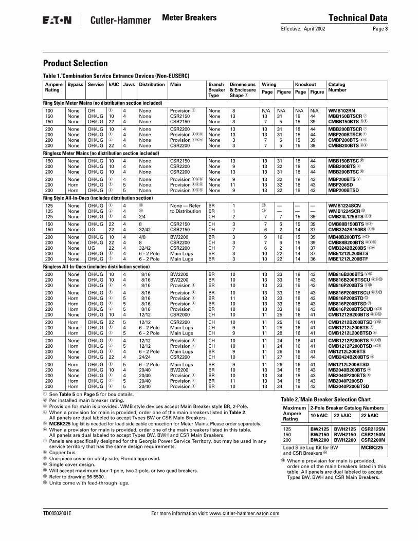
Product Selection
Table 1. Combination Service Entrance Devices (Non-EUSERC)
1
See
Table 5
on
Page 5
for box details.
2
Per installed main breaker rating.
3
Provision for main is provided. WMB style devices accept Main Breaker style BR, 2-Pole.
4
When a provision for main is provided, order one of the main breakers listed in
Table 2
. All panels are dual labeled to accept Types BW or CSR Main Breakers.
5
MCBK225
lug kit is needed for load side cable connection for Meter Mains. Please order separately.
6
When a provision for main is provided, order one of the main breakers listed in this table. All panels are dual labeled to accept Types BW, BWH and CSR Main Breakers.
7
Panels are specifically designed for the Georgia Power Service Territory, but may be used in any service territory that has the same design requirements.
8
Copper bus.
9
One-piece cover on utility side, Florida approved.
j
Single cover design.
k
Will accept maximum four 1-pole, two 2-pole, or two quad breakers.
l
Refer to drawing 96-5500.
m
Units come with feed-through lugs.
AmpereRating
Bypass Service kAIC Jaws Distribution Main BranchBreakerType
Dimensions & EnclosureShape
1
Wiring Knockout Catalog NumberPage Figure Page Figure
Ring Style Meter Mains (no distribution section included)
100150150
NoneNoneNone
OHOH/UGOH/UG
2
1022
444
NoneNoneNone
Provision
3
CSR2150CSR2150
NoneNoneNone
813 3
N/A13 7
N/A31 5
N/A1815
N/A4439
WMB102RNMBB150BTSCR
7
CMBB150BTS
89
200200200200
NoneNoneNoneNone
OH/UGOH/UGOH/UGOH/UG
10
2
2
22
4444
NoneNoneNoneNone
CSR2200 Provision
456
Provision
456
CSR2200
NoneNoneNoneNone
1313 3 3
1313 7 7
3131 5 5
18181515
44443939
MBB200BTSCR
7
MBP200BTSCR
7
CMBP200BTS
89
CMBB200BTS
89
Ringless Meter Mains (no distribution section included)
150200200
NoneNoneNone
OH/UGOH/UGOH/UG
101010
444
NoneNoneNone
CSR2150CSR2200CSR2200
NoneNoneNone
13 913
131313
313231
181818
444344
MBB150BTSC
j
MBB200BTS
9
MBB200BTSC
j
200200200
NoneHornHorn
OH/UGOH/UGOH/UG
2
2
2
455
NoneNoneNone
Provision
456
Provision
456
Provision
456
NoneNoneNone
911 9
131313
323232
181818
434343
MBP200BTS
9
MBP200SDMBP200BTSD
Ring Style All-In-Ones (includes distribution section)
125125125
NoneNoneNone
OH/UGOH/UGOH/UG
2
2
2
444
k
k
2/4
None — Refer to Distribution
BRBRCH
1 1 2
l
l
7
—— 7
——15
——39
WMB1224SCNWMB1224SCR
j
CMB24L125BTS
89
150150
NoneNone
OH/UGUG
2222
44
832/42
CSR2150CSR2150
CHCH
3 7
7 6
6 2
1514
3937
CMB88B150BTS
89
CMB3242B150BS
89
200200200200200
NoneNoneNoneNoneNone
OH/UGOH/UGUGOH/UGOH/UG
102222
3
3
44444
4/8832/426 – 2 Pole6 – 2 Pole
BW2200CSR2200CSR2200Main LugsMain Lugs
BRCHCHBRBR
3 3 7 3 3
9 7 61010
16 6 22222
1515141414
3939373736
MB48B200BTS
9
m
CMB88B200BTS
89
m
CMB3242B200BS
89
MBE1212L200BTSMBE1212L200BTF
Ringless All-In-Ones (includes distribution section)
200200200
NoneNoneNone
OH/UGOH/UGOH/UG
1010
2
444
8/16 8/16 8/16
BW2200BW2200Provision
4
BRBRBR
101010
131313
333333
181818
434343
MB816B200BTS
9
m
MB816B200BTSCU
89
m
MB816P200BTS
9
m
200200200200200
NoneHornHornHornNone
OH/UGOH/UGOH/UGOH/UGOH/UG
2
2
2
2
10
45554
8/16 8/16 8/16 8/1612/12
Provision
4
Provision
4
Provision
4
ProvisionCSR2000
BRBRBRBRCH
1011101010
1313131311
3333333325
1818181816
4343434341
MB816P200BTSCU
89
m
MB816P200STD
m
MB816P200BTSD
m
MB816P200BTSCUD
8
m
CMB1212B200BTS
89
m
200200200
HornNoneHorn
OH/UGOH/UGOH/UG
22
2
2
545
12/126 – 2 Pole6 – 2 Pole
CSR2200Main LugsMain Lugs
CHCHCH
10 9 9
111111
252828
161616
414141
CMB1212B200BTSD
8
m
CMB1212L200BTS
8
CMB1212L200BTSD
8
200200200200
NoneHornNoneNone
OH/UGOH/UGOH/UGOH/UG
2
2
2
22
4544
12/1212/126 – 2 Pole24/24
Provision
4
Provision
4
Main LugsCSR2200
CHCHBRCH
1010 910
11111111
24242627
16161618
41414144
CMB1212P200BTS
89
m
CMB1212P200BTSD
8
m
MB1212L200BTSCMB2424B200BTS
8
200200200200200
HornNoneNoneHornHorn
OH/UGOH/UGOH/UGOH/UGOH/UG
2
10
2
2
2
54455
6 – 2 Pole20/4020/4020/4020/40
Main LugsBW2200Provision
4
Provision
4
Provision
4
BRBRBRBRBR
910101110
1113131313
2634343434
1618181818
4143434343
MB1212L200BTSDMB2040B200BTS
9
MB2040P200BTS
9
MB2040P200SDMB2040P200BTSD
Table 2. Main Breaker Selection Chart
n
When a provision for main is provided, order one of the main breakers listed in this table. All panels are dual labeled to accept Types BW, BWH and CSR Main Breakers.
MaximumAmpereRating
2-Pole Breaker Catalog Numbers
10 kAIC 22 kAIC 22 kAIC
125150200
BW2125BW2150BW2200
BWH2125BWH2150BWH2200
CSR2125NCSR2150NCSR2200N
Load Side Lug Kit for BW and CSR Breakers
n
MCBK225

For more information visit: www.cutler-hammer.eaton.com TD00502001E
Technical Data
Page
4
Effective: April 2002
Meter Breakers
Table 3. Combination Service Entrance Devices (EUSERC)
1
See
Table 5
on
Page 5
for box details.2 Interrupting rating is dependent on the main breaker that is installed.3 Unit has copper bus.4 When a provision for main is provided, order one of the main breakers listed in Table 2.
All panels are dual labeled to accept Types BW or CSR Main Breakers.5 Semi-flush flange, not full stucco flange.6 Units come with feed-through lugs.7 Includes factory mounted 2-1/2 inch hub on bottom endwall. UG feed only.8 Use WMB70SMK if second main kit is needed.
AmpereRating
Bypass Service kAIC Jaws Distrib-ution
Main BranchBreakerType
Dimen-sions &EnclosureShape 1
Wiring Knockout Catalog Number
Page Fig. Page Fig. Surface Flush
Ring Style Meter Mains (no distribution section included)125125150
NoneNoneNone
OH/UGOH/UGOH/UG
2
2
10
444
2/4 2/4None
MLOMLOBW2150
BRCHNone
2 2 3
9 7 9
14 718
151515
39, 3839, 3839, 38
MBE24L125BTSCMBE24L125BTS 3
MBEB150BTS
MBE24L125BTFCMBE24L125BTF 3
MBEB150BTF
150200200
NoneNoneNone
OH/UGOH/UGOH/UG
221022
444
NoneNoneNone
CSR2150NBW2200CSR2200N
NoneNoneNone
3 3 3
7 9 7
518 5
151515
39, 3839, 3839, 38
CMBEB150BTS 3
MBEB200BTSCMBEB200BTS 3
CMBEB150BTF 3
MBEB200BTFCMBEB200BTF 3
200200200
NoneNoneNone
OH/UGOH/UGOH/UG
2
2
2
444
2/4 2/4None
MLOMLOProvision
BRCHNone
3 3 3
9 7 9
15 918
151515
39, 3839, 3839
MBE24L200BTSCMBE24L200BTS 3
MBEP200BTS 4
MBE24L200BTFCMBE24L200BTF 3
N/A
Ring Style All-In-Ones (includes distribution section)100100100
NoneNoneNone
OH/UGUGUG
101010
444
12/2414/2822
BR2100BR2100CH2100X
BRBRCH
2 4 5
7 8 6
812 3
151414
39, 3837, 3637, 36
MBE1224B100BTSMBE1428B100BSCMBE2222B100BS 3
MBE1224B100BTFMBE1428B100BFCMBE2222B100BF 3
100125125
NoneNoneNone
OHOH/UGOH
101010
444
12/2412/2412/24
BR2100BR2125BR2125
BRBRBR
9 2 9
13 713
35 835
161516
41, 4039, 3841, 40
MBE1224B100TSMBE1224B125BTSMBE1224B125TS
MBE1224B100TF 5
MBE1224B125BTFMBE1224B125TF 5
125125125
NoneNoneNone
UGUGUG
101010
444
14/2818/3622
BR2125BR2125CH2125X
BRBRCH
4 5 5
8 8 6
1211 3
141414
37, 3637, 3637, 36
MBE1428B125BSMBE1836B125BSCMBE2222B125BS 3
MBE1428B125BFMBE1836B125BFCMBE2222B125BF 3
150150150
NoneNoneNone
OH/UGUGUG
222210
444
832/4220/40
CSR2150NCSR2150NBW2150
CHCHBR
3 7 6
7 6 8
6 210
151414
39, 3837, 3637, 36
CMBE88B150BTS 36
CMBE3242B150BS 3
MBE2040B150BS
CMBE88B150BTF 36
CMBE3242B150BF 3
MBE2040B150BF
150150200
NoneNoneNone
OH/UGOH/UGOH/UG
101010
444
4/8 8 4/8
BW2150BW2150BW2200
BRBRBR
3 3 3
9 9 9
161716
151515
39, 3839, 3839, 38
MBE48B150BTSMBE88B150BTSMBE48B200BTS 6
MBE48B150BTFMBE88B150BTFMBE48B200BTF 6
200200200
NoneNoneNone
OH/UGOH/UGOH/UG
22102
444
8 8 8/16
CSR2200NBW2200Provision
CHBRBR
3 310
7 910
61719
151516
39, 3839, 3841
CMBE88B200BTS 36
MBE88B200BTSMBE816P200TSCU 34
CMBE88B200BTF 36
MBE88B200BTFN/A
200200200
NoneNoneNone
OHOHUG
2
2
2
444
8/166 – 2 Pole6 – 2 Pole
ProvisionMain LugMain Lug
BRCHCH
10 9 5
1010 6
1923 4
161614
414137, 36
MBE816P200TS 46
CMBE1212L200TS 3
CMBE1212L200BS 3
N/AN/ACMBE1212L200BF 3
200200200
NoneNoneNone
OHUGOH
2
2
10
444
6 – 2 Pole6 – 2 Pole20/40
Main LugMain LugBW2200
BRBRBR
9 510
10 810
211320
161416
4137, 3641, 40
MBE1212L200TSMBE1212L200BSMBE2040B200TS
N/AMBE1212L200BFMBE2040B200TF
200200200
NoneNoneNone
UGOHUG
102
22
444
20/4020/4032/42
BW2200ProvisionCSR2200N
BRBRCH
610 7
810 6
1020 2
141614
37, 3641, 4037, 36
MBE2040B200BSMBE2040P200TS 4
CMBE3242B200BS 3
MBE2040B200BFMBE2040P200TF 45
CMBE3242B200BF 3
200200
NoneNone
UGUG
2222
44
4042
BWH2200CSR2200
BRCH
1212
1212
3029
1717
4242
MBE4040B200BSH 7
CMBE4242B200BSH 37N/AN/A
200200200
NoneNoneNone
OH/UGOH/UGOH/UG
222210
444
404220/40
BWH2200CSR2200NBW2200
BRCHBR
1212—
1212—
3029—
1717—
4242—
MBE4040B200BTSCMBE4242B200BTS 3
MBE2040B200BTS
MBE4040B200BTF 5
CMBE4242B200BTF 35
MBE2040B200BTF
200225225
NoneNoneNone
OH/UGOH/UGUG
101022
444
4/820/4032/42
BW2200BW2225CSR2225N
BRBRCH
—— 7
—— 6
—— 2
——14
——37, 36
WMB2048SLB 8
MBE2040B225BTSCMBE3242B225BS 3
N/AMBE2040B225BTFCMBE3242B225BF 3
Table 4. Main Breaker Selection Chart
9 When a provision for main is provided, order one of the main breakers listed in this table. All panels are dual labeled to accept Types BW, BWH and CSR Main Breakers.
MaximumAmpereRating
2-Pole Breaker Catalog Numbers
10 kAIC 22 kAIC 22 kAIC
125150200
BW2125BW2150BW2200
BWH2125BWH2150BWH2200
CSR2125NCSR2150NCSR2200N
Load Side Lug Kit for BW and CSR Breakers 9
MCBK225

TD00502001E For more information visit: www.cutler-hammer.eaton.com
Technical DataEffective: April 2002 Page 5
Meter Breakers
Box Styles
Figure 1. Five Different Styles (Shapes) of Product
Table 5. Box Dimensions
Table 6. Meter Breaker Parts
Table 7. Wire Size Chart
Table 8. Wire Size is Determined by the Circuit Breaker Installed in the Enclosure. Maximum Wire Size and Ampere Rating is Determined as Follows:
Table 9. Hub Selection Chart
A B C D E
BoxNumber
Dimensions in Inches (mm) BoxStyleHeight Width Depth
1 2 3
12-1/2 (317.5)23-7/8 (606.4)28-3/8 (720.7)
14-7/16 (366.7)14-7/16 (366.7)14-7/16 (366.7)
4 (101.6)5-3/8 (136.5)5-3/8 (136.5)
AAA
4 5 6
34-1/8 (866.8)36-1/8 (917.6)43-3/8 (1101.7)
14-7/16 (366.7)14-7/16 (366.7)14-7/16 (366.7)
5-3/8 (136.5)5-3/8 (136.5)5-3/8 (136.5)
BBB
7 8 9
46-7/8 (1190.6)19-3/4 (501.7)25-3/8 (644.5)
14-7/16 (366.7) 7-1/2 (190.5)14-7/16 (366.7)
5-3/8 (136.5)4 (101.6)5-3/8 (136.5)
BCC
10111213
32-3/8 (822.3)36-5/8 (930.3)34-3/8 (873.1)19-3/4 (501.7)
14-7/16 (366.7)14-7/16 (366.7)22 (558.8)14-7/16 (366.7)
5-3/8 (136.5)5-3/8 (136.5)5-3/8 (136.5)5-3/8 (136.5)
CCDE
Description CatalogNumber
5th Jaw KitsCompact and Standard Styles (MB & CMB)WMB Style
1MM5JKOPWMB5J
Manual Bypass KitsRing Style Units Only (MB) 1MMBPM200
Horn Bypass KitsRingless Style Units Only (MB & CMB) 1MMBPH
Main Wire Size Range Cu/Al 60ºC or 75ºC for Line Terminals
BR250BR260BR270
#14 – 4 kcmil #4 – 1/0 kcmil #4 – 1/0 kcmil
BR280BR290BR2100
#4 – 1/0 kcmil #4 – 1/0 kcmil #4 – 1/0 kcmil
BW2125BW2150BW2200
#2 – 300 kcmil #2 – 300 kcmil #2 – 300 kcmil
BWH2125BWH2150BWH2200
#2 – 300 kcmil #2 – 300 kcmil #2 – 300 kcmil
CSR2125NCSR2150NCSR2200N
#1/0 – 250 kcmil#1/0 – 250 kcmil#1/0 – 250 kcmil
125A Main Lugs 200A Main LugsMCBK225
—— #2 – 300 kcmil
Wire/Application Maximum
Wire Size
AmpereRating
Aluminum — StandardAluminum — Service EntranceCopper — Standard and Service Entrance
250 kcmil250 kcmil250 kcmil
200225225
Hub SizeDimensions in Inches (mm)
Catalog Number
1 (25.4)1-1/4 (31.8)1-1/2 (38.1)
DS100H2DS125H2DS150H2
2 (50.8)2-1/2 (63.5)3 (76.2)
DS200H2DS250H2DS300H2

For more information visit: www.cutler-hammer.eaton.com TD00502001E
Technical DataPage 6 Effective: April 2002
Meter Breakers
Typical Wiring Diagrams (Residential Meter Breakers)
Figure 2. Catalog Numbers — CMB3242B200BS, CMBE3242B150BS, CMBE3242B150BF, CMBE3242B200BS, CMBE3242B200BF, CMBE3242B225BS, CMBE3242B225BF and CMB3242B150BS
#14-2 AWG#14-4 AWG#6-2/0 AWG#6-250 AWG
Wiring Diagram Key
Service DisconnectType CSR
N
BondedNeutral
BondedNeutral
123456789
10111213
14
15
16
17
18
19
20
21
22
23242526272829303132
33
34
35
36
37
38
39
40
41
42
Line
A BFigure 3. Catalog Numbers — CMBE2222B125BS, CMBE2222B125BF, CMBE2222B100BS and CMBE2222B100BF
Figure 4. Catalog Numbers — CMBE1212L200BS and CMBE1212L200BF
1416
22
9111315
10
468
1357
2
1820
1719
NA B
Line
#14-4 AWG#6-2/0 AWG
#6-250 AWG
Wiring Diagram Key
4
8
12
13
7
11
2
A B
NLine
Bo
nd
ed N
eutr
al
Bo
nd
ed N
eutral
#14-4 AWG#6-1/0 AWG#6-250 AWG
Wiring Diagram Key

TD00502001E For more information visit: www.cutler-hammer.eaton.com
Technical DataEffective: April 2002 Page 7
Meter Breakers
Typical Wiring Diagrams (Residential Meter Breakers)
Figure 5. Catalog Numbers — CMBP200BTS, CMBB150BTS, CMBB200BTS, CMBEB150BTF, CMBEB150BTS, CMBEB200BTF and CMBEB200BTS1 Factory installed MCBK225 Kit for C/B load lugs.
Figure 6. Catalog Numbers — CMBE88B200BTS, CMBE88B200BTF, CMB88B200BTS, CMB88B150BTS, CMBE88B150BTS and CMBE88B150BTF
Figure 7. Catalog Numbers — CMBE24L125BTS, CMBE24L125BTF and CMB24L125BTS
Figure 8. Catalog Numbers — MBE1224B100BTS, MBE1224B100BTF, MBE1224B125BTS and MBE1224B125BTF
Figure 9. Catalog Numbers — CMBE24L200BTS and CMBE24L200BTF
A B
BondedNeutral
LineN
A B
Install 200A MaximumService Disconnect Type CSR ➀
Wiring Diagram Key
#14-2/0 AWG#14-2 AWG#6-250 AWG
A B
1234
A B
5678
Wiring Diagram Key
#14-1/0 AWG#14-6 AWG#6-2/0 AWG#6-250 AWG#4-300 AWG
Service DisconnectType CSR 200A Maximum
LineN
A B
BondedNeutral
LineN
A B
#14-1/0 AWG#14-6 AWG#14-1/0 AWG#6-250 AWG
1 3 4
Wiring Diagram Key
1234
#14-6 AWG#14-1/0 AWG#14-2/0 AWG#6-250 AWG
WiringDiagram Key
A
BondedNeutral
B
Main56789
101112131415161718192021222324
A B
BondedNeutralLine
N
A B
#14-6 AWG#14-1/0 AWG#6-250 AWG
1 3 4
Wiring Diagram Key

For more information visit: www.cutler-hammer.eaton.com TD00502001E
Technical DataPage 8 Effective: April 2002
Meter Breakers
Typical Wiring Diagrams (Residential Meter Breakers)
Figure 10. Catalog Numbers — MBE2040B150BS, MBE2040B150BF, MBE2040B200BS and MBE2040B200BF
Figure 11. Catalog Numbers — MBE1836B125BS and MBE1836B125BF
Figure 12. Catalog Numbers — MBE1428B100BS, MBE1428B100BF, MBE1428B125BS and MBE1428B125BF
Figure 13. Catalog Numbers — MBE1212L200BS and MBE1212L200BF
N
A B
142
35 6
91113151719
323133 34
374038
39
DisconnectType BW, BWH or CSR
Line
#14-4 AWG#6-2/0 AWG#6-250 AWG
Wiring Diagram Key
135
91113151719
23
3635
25272931
N Line
A B
Service Disconnect
Wiring Diagram Key
#14-4 AWG#6-2/0 AWG
#6-250 AWG
135
911131517192123
NLine
A B
Bo
nd
ed N
eutr
al
Bo
nd
ed N
eutral
Wiring Diagram Key
#14-4 AWG#6-2/0 AWG
#6-250 AWG
68
1012
13579
11
2
Line
A B
N
Bo
nd
ed N
eutr
al
#14-6 AWG#6-1/0 AWG#6-250 AWG
Bo
nd
ed N
eutral
Wiring Diagram Key

TD00502001E For more information visit: www.cutler-hammer.eaton.com
Technical DataEffective: April 2002 Page 9
Meter Breakers
Typical Wiring Diagrams (Residential Meter Breakers)
Figure 14. Catalog Numbers — MBE24L125BTS and MBE24L125BTF
Figure 15. Catalog Numbers — MBE24L200BTS and MBE24L200BTF
Figure 16. Catalog Numbers — MBE48B150BTS, MBE48B150BTF, MBE48B200BTS, MBE48B200BTF and MB48B200BTS
Figure 17. Catalog Numbers — MBE88B200BTS, MBE88B200BTF, MBE88B150BTS and MBE88B150BTF
Figure 18. Catalog Numbers — MBEP200BTS, MBEB200BTS, MBEB200BTF, MBEB150BTS and MBEB150BTF
A B
1
NeutralLineN
A B
2 34 56
#14-1/0 AWG#14-6 AWG#14-2/0 AWG#6-250 AWG
Wiring Diagram Key
A B
1
NeutralLine
NA B
2 34 56
#14-1/0 AWG#14-6 AWG#14-2/0 AWG#6-250 AWG
Wiring Diagram Key
A B
200A MaximumService DisconnectType BW, BWH or CSR
A B L2L1 BondedNeutral
LineN
#14-1/0 AWG#14-6 AWG#6-2/0 AWG#6-250 AWG
Wiring Diagram Key
678
A B
200A MaximumService DisconnectType BW, BWH or CSR
A BLineN
Wiring Diagram Key
#14-1/0 AWG#14-6 AWG#6-2/0 AWG#6-250 AWG
A B
A B
MCBK225 Kit forC/B Load Lugs
Wiring Diagram Key
#14-2/0 AWG#6-2/0 AWG#6-250 AWG
200A MaximumService DisconnectType BW, BWH or CSR
BondedNeutral
LineN

For more information visit: www.cutler-hammer.eaton.com TD00502001E
Technical DataPage 10 Effective: April 2002
Meter Breakers
Typical Wiring Diagrams (Residential Meter Breakers)
Figure 19. Catalog Numbers —MBE816P200TS and MBE816P200TSCU
Figure 20. Catalog Numbers — MBE2040P200TS, MBE2040P200TF, MBE2040B200TS and MBE2040B200TF
Figure 21. Catalog Number — MBE1212L200TS
Figure 22. Catalog Numbers — MBE1212L200BTS and MBE1212L200BTF
Figure 23. Catalog Number — CMBE1212L200TS
A B
#14-4 AWG#6-350 kcmil#6-2/0 AWG#6-300 kcmil#6-300 kcmil
LineN
BondedNeutral
200A MaximumService DisconnectType BW, BWH or CSR
Wiring Diagram Key
A B
Line N
BondedNeutral
200A MaximumService DisconnectType BW, BWH or CSR
13
24
8
#14-4 AWG#6-350 kcmil#6-2/0 AWG
1
3
5
7
9
11
BondedNeutral
N
A B
#14-4 AWG#6-350 kcmil#6-2/0 AWG#6-300 kcmil
2
4
6
8
10
12
Wiring Diagram Key
A B
1
2
3
LINE N
A B 4
5
6
BondedNeutral
#14-4 AWG#6-350 kcmil#6-2/0 AWG
Wiring Diagram Key
1
3
5
7
9
11
#14-4 AWG#6-350 kcmil#6-2/0 AWG#6-300 kcmil
BondedNeutral
A BN
2
4
6
8
10
12
Wiring Diagram Key

TD00502001E For more information visit: www.cutler-hammer.eaton.com
Technical DataEffective: April 2002 Page 11
Meter Breakers
Typical Wiring Diagrams (Residential Meter Breakers)
Figure 24. Catalog Numbers — CMB1212P200BTSD and CMB1212P200BTS
Figure 25. Catalog Numbers — CMB1212B200BTS and CMB1212B200BTSD
Figure 26. Catalog Numbers — MB1212L200BTS and MB1212L200BTSD
Figure 27. Catalog Number — CMB2424B200BTS
Figure 28. Catalog Numbers — CMB1212L200BTSD and CMB1212L200BTS
5TH Jaw Factory Installedon CMB1212B200BTSD andCMB1212P200BTSD Only
1
3
5
7
9
11
200A MaximumService DisconnectType CSR
BondedNeutral
LineN
A B
2
4
6
8
10
12
#14-4 AWG#6-350 kcmil#6-2/0 AWG#4-300 kcmil#6-300 kcmil
WiringDiagram Key
5th Jaw Factory Installedon CMB1212B200BTSD andCMB1212P200BTSD Only
1
3
5
7
9
11
#14-4 AWG#6-350 kcmil#6-2/0 AWG#4-300 kcmil#6-300 kcmil
200A MaximumService DisconnectType CSR
BondedNeutral
LineN
A B
2
4
6
8
10
12
WiringDiagram Key
1
3
5
7
9
11
BondedNeutral N
A B
Ground Bar
#14-2/0 AWG#6-350 kcmil#6-300 kcmil
2
4
6
8
10
12
WiringDiagram Key
1
3
5
7
9
11
13
15
17
19
21
23
#14-4 AWG#6-350 kcmil#6-2/0 AWG#4-300 kcmil
200A MaximumService DisconnectType CSR
BondedNeutral
LineN
A B
2
4
6
8
10
12
14
16
18
20
22
24
WiringDiagram Key
1
3
5
7
9
11
N
BondedNeutral
A B
#14-4 AWG#6-350 kcmil#6-2/0 AWG#6-300 kcmil
5th Jaw Factory Installedon CMB1212L200BTSD Only
2
4
6
8
10
12WiringDiagram Key

For more information visit: www.cutler-hammer.eaton.com TD00502001E
Technical DataPage 12 Effective: April 2002
Meter Breakers
Typical Wiring Diagrams (Residential Meter Breakers)
Figure 29. Catalog Numbers — CMBE4242B200BSH, CMBE4242B200BTS and CMBE4242B200BTF
Figure 30. Catalog Numbers — MBE4040B200BTF, MBE4040B200BTS and MBE4040B200BSH
13579
11131517192123252729313335373941
#14-6 AWG#14-1/0 AWG#6 AWG-250 kcmil
WiringDiagram Key
N
A B
A B
Factory InstalledService DisconnectType CSR
BondedNeutral
2468
1012141618202224262830323436384042
13579
111315171921232527293133353739
#14-6 AWG#14-1/0 AWG#6 AWG-250 kcmil
WiringDiagram Key
N
A B
A B
Factory InstalledService DisconnectType BW
BondedNeutral
2468
10121416182022242628303234363840

TD00502001E For more information visit: www.cutler-hammer.eaton.com
Technical DataEffective: April 2002 Page 13
Meter Breakers
Typical Wiring Diagrams (Non-EUSERC Meter Breaker Design)
Figure 31. Catalog Numbers — MBB150BTSC, MBB150BTSCR, MBB200BTSCR, MBP200BTSCR and MBB200BTSC
Figure 32. Catalog Numbers — MBP200SD, MBB200BTS, MBP200BTS and MBP200BTSD1 Use MCBK225 for C/B Load Lugs.
Figure 33. Catalog Numbers — MB816P200STD, MB816B200BTS, MB816B200BTSCU, MB816P200BTS, MB816P200BTSCU, MB816P200BTSD and MB816P200BTSCUD
Figure 34. Catalog Numbers — MB2040P200SD, MB2040B200BTS, MB2040P200BTS and MB2040P200BTSD
Figure 35. Catalog Numbers — MBE1224B125TS, MBE1224B125TF, MBE1224B100TS and MBE1224B100TF
A B
200A MaximumService DisconnectType CSR
BondedNeutral
Line N
#6-2/0 AWG#6-350 kcmil#6-250 kcmil#1-300 kcmil
Included inMBB150BTSCR
Wiring Diagram Key
A B
#6-2/0 AWG#6-350 kcmil#1-300 kcmil#6-300 kcmil
LineN
BondedNeutral
200A MaximumService DisconnectType BW, BWH or CSR ➀
Wiring Diagram Key
A B
13
24
81012
15 16
#14-4 AWG#6-350 kcmil#6-2/0 AWG#6-300 kcmil#6-300 kcmil
LineN
BondedNeutral
200A MaximumService
Type BW,
Wiring Diagram Key
A B
13
24
810121416182022
262830
34363840
32
LineN
BondedNeutral
200A MaximumService DisconnectType BW, BWH or CSR
#14-4 AWG#6-350 kcmil#6-2/0 AWG
Wiring
#14-4 AWG#14-1/0 AWG#6-350 kcmil
WiringDiagram Key
13579
11131517192123
125A MaximumService DisconnectType BR, or BRH
BondedNeutral
LineN
A B
EquipmentGround
2468
1012141618202224

For more information visit: www.cutler-hammer.eaton.com TD00502001E
Technical DataPage 14 Effective: April 2002
Meter Breakers
Dimensions and Knockouts (Residential Meter Breakers) — Dimensions in Inches (mm)
Figure 36. Knockouts for Stucco and Surface Units Catalog Numbers — CMBE3242B150BF, CMBE3242B200BF, CMBE3242B225BF, CMBE2222B100BF, CMBE2222B125BF, CMBE1212L200BF, MBE2040B200BF, MBE2040B150BF, MBE1428B100BF, MBE1428B125BF, MBE1212L200BF, MBE1212L200BTF and MBE1836B125BF
Table 10. Top Endwall (Surface)
1 Use when DS H1 Type 1, 1-1/4 and 1-1/2-inch hubs are needed.
Table 11. Top Endwall (Stucco)
Figure 37. Knockouts for Stucco and Surface Units Catalog Numbers — CMBE3242B150BS, CMBE3242B200BS, CMBE3242B225BS, CMBE2222B100BS, CMBE2222B125BS, CMBE1212L200BS, MBE2040B200BS, MBE2040B150BS, MBE1428B100BS, MBE1428B125BS, MBE1212L200BS, MBE1212L200BTS, MBE1836B125BS, CMB3242B150BS and CMB3242B200BS
Table 12. Bottom EndwallHub Provision
DS100H2DS125H2DS150H2
DS200H2DS250H2DS300H2DS900AP (Adapter Plate if using DS___H1 hubs only) 1
Knockout Size (Dimensions in Inches)
Quantity
1-1/4, 1-1/2, 2, 2-1/21, 1-1/4, 1-1/21/2, 3/4, 1
111
1/2, 3/41/2
57
3-1/2(88.9)
Keyhole Knockouts on Sides for Stucco Units Only.
Top Stucco
4-15/16(125.4)
Bottom
Knockout Size (Dimensions in Inches)
Quantity
1/2,1/2, 3/41/2, 3/4, 1
741
1, 1-1/4, 1-1/2, 21-1/4, 1-1/2, 2, 2-1/2, 3
11
5-5/16(134.9)
Top Surface
Bottom
4-15/16(125.4)

TD00502001E For more information visit: www.cutler-hammer.eaton.com
Technical DataEffective: April 2002 Page 15
Meter Breakers
Dimensions and Knockouts (Residential Meter Breakers) — Dimensions in Inches (mm)
Figure 38. Knockouts for Stucco and Surface Units Catalog Numbers — CMBE24L200BTF, CMBE24L125BTF, CMBEB200BTF, CMBEB150BTF, CMBE88B150BTF, CMBE88B200BTF, MBE24L125BTF, MBE24L200BTF, MBE48B150BTF, MBE48B200BTF, MBE88B150BTF, MBE88B200BTF, MBEB150BTF, MBEB200BTF, MBE1224B100BTF and MBE1224B125BTF
Table 13. Top Endwall (Surface)
1 Use when DS H1 Type 1, 1-1/4 and 1-1/2-inch hubs are needed.
Table 14. Top Endwall (Stucco)
Figure 39. Knockouts for Stucco and Surface Units Catalog Numbers — CMBB150BTS, CMBB200BTS, CMBE24L125BTS, CMB24L125BTS, CMBE24L200BTS, CMBEB200BTS, CMBEB150BTS, CMBE88B150BTS, CMBE88B200BTS, CMBP200BTS, MBE24L125BTS, MBE24L200BTS, MBE48B150BTS, MBE48B200BTS, MBE88B150BTS, MBE88B200BTS, MBEB150BTS, MBEB200BTS, MBEP200BTS, MBE1224B100BTS, MBE1224B125BTS, CMB88B150BTS, CMB88B200BTS and MB48B200BTS
Table 15. Bottom EndwallHub Provision
DS100H2DS125H2DS150H2
DS200H2DS250H2DS300H2DS900AP (Adapter Plate) 1
Knockout Size (Dimensions in Inches)
Quantity
1-1/4, 1-1/2, 2, 2-1/21, 1-1/4, 1-1/21/2, 3/4, 1
111
1/2, 3/41/2
33
Keyhole Knockouts on Sides for Stucco Units Only.
Top Stucco
Bottom
3-1/2(88.9)
4-15/16(125.4)
Knockout Size (Dimensions in Inches)
Quantity
1/21/2, 3/41/2, 3/4, 1
741
1, 1-1/4, 1-1/2, 21-1/4, 1-1/2, 2, 2-1/2, 3
11
Top Surface
Bottom
5-5/16(134.9)
4-15/16(125.4)

For more information visit: www.cutler-hammer.eaton.com TD00502001E
Technical DataPage 16 Effective: April 2002
Meter Breakers
Dimensions and Knockouts (Residential Meter Breakers) — Dimensions in Inches (mm)
Figure 40. Knockouts for Stucco and Surface Units Catalog Numbers — MBE1224B100TF, MBE1224B125TF, MBE2040B200TF and MBE2040P200TF
Table 16. Top Endwall (Surface)
1 Use when DS H1 Type 1, 1-1/4 and 1-1/2-inch hubs are needed.
Table 17. Top Endwall (Stucco)
Figure 41. Knockouts for Stucco and Surface Units Catalog Numbers — MBE1224B100TS, MBE1224B125TS, MBE816P200TS, MBE816P200TSCU, MBE2040B200TS, MBE2040P200TS, MBE1212L200TS, CMBE1212L200TS, CMB1212P200BTS, CMB1212P200BTSD, CMB1212B200BTS, CMB1212B200BTSD, MB1212L200BTS, MB1212L200BTSD, CMB1212L200BTS and CMB1212L200BTSD
Table 18. Bottom EndwallHub Provision
DS100H2DS125H2DS150H2
DS200H2DS250H2DS300H2DS900AP (Adapter Plate) 1
Knockout Size (Dimensions in Inches)
Quantity
1-1/4, 1-1/2, 2, 2-1/21, 1-1/4, 1-1/21/2, 3/4, 1
111
1/2, 3/41/2
57
Keyhole Knockouts on Sides for Stucco Units Only.
Top Stucco
Bottom
3-1/2(88.9)
4-15/16(125.4)
Knockout Size (Dimensions in Inches)
Quantity
1/21/2, 3/41/2, 3/4, 1
741
1, 1-1/4, 1-1/2, 21-1/4, 1-1/2, 2, 2-1/2, 3
11
Top Surface
Bottom
5-5/16(134.9)
4-15/16(125.4)

TD00502001E For more information visit: www.cutler-hammer.eaton.com
Technical DataEffective: April 2002 Page 17
Meter Breakers
Dimensions and Knockouts (Residential Meter Breakers) — Dimensions in Inches (mm)
Figure 42. Knockouts for Stucco and Surface Units
Table 19. Top Endwall (Surface)
1 Use when DS H1 Type 1, 1-1/4 and 1-1/2-inch hubs are needed.
Table 20. Top Endwall (Stucco) Table 21. Bottom Endwall
3-7/16(87.3)
Top Surface
Top Flush
CMBE4242B200BTFMBE4040B200BTF
Top Surface
Bottom Bottom
2-1/2-inch Hub
CMBE4242B200BTSMBE4040B200BTS
CMBE4242B200BSHMBE4040B200BSH
5-5/16(134.9)
4-15/16(125.4)
5-5/16(134.9)
4-15/16(125.4)
Hub Provision
DS100H2DS125H2DS150H2
DS200H2DS250H2DS300H2DS900AP (Adapter Plate) 1
Knockout Size (Dimensions in Inches)
Quantity
1-1/4, 1-1/2, 2, 2-1/21/2, 3/4
23
Knockout Size (Dimensions in Inches)
Quantity
1/2, 3/41/2, 3/4, 1, 1-1/41, 1-1/4, 1-1/2, 2, 2-1/21, 1-1/4, 1-1/2, 2, 2-1/2, 3
6211

For more information visit: www.cutler-hammer.eaton.com TD00502001E
Technical DataPage 18 Effective: April 2002
Meter Breakers
Dimensions and Knockouts (Non-EUSERC Meter Breaker Design) — Dimensions in Inches (mm)
Figure 43. Knockouts for Non-EUSERC Units Catalog Numbers — MB2040P200BTSD, MBB200BTS, MBP200BTS, MB816P200BTS, MB816P200BTSCU, MB816B200BTS, MB816P200BTSD, MB816B200BTSCU, MB816B200BTSD, MB2040P200BTS, MB2040B200BTS, MBP200BTSD, MBP200SD, MB816P200STD, MB816P200BTSCUD and MB2040P200SD
Table 22. Top Endwall (Surface)
1 Use when DS H1 Type 1, 1-1/4 and 1-1/2-inch hubs are needed.
Figure 44. Knockouts for Non-EUSERC Units Catalog Numbers — CMB2424B200BTS, MBB150BTSCR, MBB200BTSCR, MBP200BTSCR, MBB150BTSC and MBB200BTSC
Table 23. Bottom EndwallHub Provision
DS100H2DS125H2DS150H2DS200H2DS250H2DS300H2DS900AP (Adapter Plate) 1
5-5/16(134.9)
Top Surface
Bottom
4-15/16(125.4)
Knockout Size (Dimensions in Inches)
Quantity
5/161/21/2, 3/43/4, 11-1/4, 1-1/2, 2, 2-1/21-1/2, 2, 2-1/2, 3
332121
Bottom
4-15/16(125.4)
5-5/16(134.9)
Top Surface (Catalog Numbers with SC and SCR Suffix Only)

TD00502001E For more information visit: www.cutler-hammer.eaton.com
Technical DataEffective: April 2002 Page 19
Meter Breakers
Type CH Residential 300 Ampere and 400 Ampere “House Panels”
Type CH Residential — 300 Ampere and 400 Ampere “House Panels”
Product DescriptionA “House Panel” is a service entrance device that consists of a meter socket and a distribution section. The unit is rated at 300 amperes or 400 amperes.
Application DescriptionIn addition to residential installations, a “house panel” could also be used for an apartment/condominium, clubhouse or common area.
Features, Benefits and Functions
300 Ampere and 400 Ampere “House Panels”■ Underground feed only.■ “DS_H2” type hub provisions on
bottom endwall.■ “Ring Style Units” meet EUSERC
requirements.■ Plug-on 400 ampere meter socket
(320 ampere continuous).■ NEMA 3R — rainproof.■ Lever bypass socket available
on certain catalog numbers.■ Service entrance equipment and
UL listed.■ Uses CH branch breakers.■ Box type lug kit available —
HPBLK750.
Product SelectionTable 24. 300 – 400 Ampere “House Panels”
1 Confirm security type for individual EUSERC utility requirements.2 Semi-Flush Flange kit — HPPR.3 If manual bypass is needed, order bypass kit HPBPK.4 Feed-through lugs included.
AmpereRating
Security1 Bypass MainBreaker (Included)
Optional MainBreaker(Not Included)
ServiceType
kAIC Distrib-ution
Wiring Diagram Line SideMain Lugsand Neutral
Catalog Number
Page Figure Surface Semi-Flush 2
300300300300
RingRingRinglessRingless
None 3None 3LeverLever
BW2200BW2200CSR2200NCSR2200N
CHCHCHBCHB
UGUGUGUG
101022/1022/10
32/42None42None
20202020
51494745
Landing studs for utilitysuppliedcompressionlugs.
CG303242SCG30SCG304242SHLCG30SHL
————
400400400400400
RingRingRingRingRing
None 3None 3None 3None 3None 3
BW2200BW2200CSR2200NCSR2200NProvision
CHBWCSRCSRCSR
UGUGUGUGUG
101022/1022/1022
32/42NoneNone32/4212
2020202020
4648484652
CG403242SCG40SCG40SHCG403242SHCG1212P400BS 4
—————
400400
RinglessRingless
LeverLever
CSR2200NCSR2200N
CSRCSR
UGUG
22/1022/10
42None
2020
5048
CG404242SHLCG40SHL
——

For more information visit: www.cutler-hammer.eaton.com TD00502001E
Technical DataPage 20 Effective: April 2002
Meter Breakers
Technical Data and Specifications
Typical Wiring Diagrams (Type CH Style House Panels)
Figure 45. Type CH Wiring Diagram 1 —Catalog Number CG30SHL
Figure 46. Type CH Wiring Diagram 2 —Catalog Numbers CG403242S and CG403242SH
Figure 47. Type CH Wiring Diagram 3 —Catalog Number CG304242SHL
Figure 48. Type CH Wiring Diagram 4 —Catalog Numbers CG40S, CG40SH and CG40SHL
Figure 49. Type CH Wiring Diagram 5 —Catalog Number CG30S
Figure 50. Type CH Wiring Diagram 6 —Catalog Number CG404242SHL
Figure 51. Type CH Wiring Diagram 7 —Catalog Number CG303242S
Figure 52. Type CH Wiring Diagram 8 —Catalog Number CG1212P400BS
Figure 53. Type CH Wiring Diagram Key
A
BONDEDNEUTRAL
EQUIPMENTGROUNDINGTERMINALS
400 AMPS(320 AMPS
CONTINUOUS)
FACTORYINSTALLED200ASERVICEDISCONNECT
N B
LINE
FACTORY/FIELDINSTALLED100A MAX.SERVICEDISCONNECTTYPE CHB
(OPTIONAL)
A
BONDEDNEUTRAL
EQUIPMENTGROUNDINGTERMINALS
400 AMPS(320 AMPS
CONTINUOUS)
FACTORYINSTALLED200ASERVICEDISCONNECT
N B
LINE
FACTORY/FIELDINSTALLED200A MAX.SERVICEDISCONNECTTYPE BW
(OPTIONAL)
1 2
3 4
5 6
11
9
7
12
10
8
13 14
15 16
17 18
19 20
2321
25
22
27
24
29
26
31
28
33
30
35
32
37
34
39
36
41
384042
A
BONDEDNEUTRAL
EQUIPMENTGROUNDINGTERMINALS
400 AMPS(320 AMPS
CONTINUOUS)
FACTORYINSTALLED200ASERVICEDISCONNECT
N B
LINE
FACTORY/FIELDINSTALLED100A MAX.SERVICEDISCONNECTTYPE CHB
1 2
3 4
5 6
11
9
7
12
10
8
13 14
15 16
17 18
19 20
21 22
23 24
25 26
27 28
29 30
31 32
33 34
35 36
37 38
39 40
41 42
(OPTIONAL)
A
BONDEDNEUTRAL
EQUIPMENTGROUNDINGTERMINALS
400 AMPS(320 AMPS
CONTINUOUS)
FACTORYINSTALLED200ASERVICEDISCONNECT
N B
LINE
FACTORY/FIELDINSTALLED200A MAX.SERVICEDISCONNECTTYPE BW
(OPTIONAL)
(OPTIONAL)
A
BONDEDNEUTRAL
EQUIPMENTGROUNDINGTERMINALS
400 AMPS(320 AMPS
CONTINUOUS)
FACTORYINSTALLED200ASERVICEDISCONNECT
N B
LINE
FACTORY/FIELDINSTALLED100A MAX.SERVICEDISCONNECTTYPE CH
A
BONDEDNEUTRAL
EQUIPMENTGROUNDINGTERMINALS
400 AMPS(320 AMPS
CONTINUOUS)
FACTORYINSTALLED200ASERVICEDISCONNECT
N B
LINE
FACTORY/FIELDINSTALLED200A MAX.SERVICEDISCONNECTTYPE CSR
1 2
3 4
5 6
11
9
7
12
10
8
13 14
15 16
17 18
19 20
21 22
23 24
25 26
27 28
29 30
31 32
33 34
35 36
37 38
39 40
41 42
(OPTIONAL)
1 2
3 4
5 6
11
9
7
12
10
8
13 14
15 16
17 18
19 20
2321
25
22
27
24
29
26
31
28
33
30
35
32
37
34
39
36
41
384042
FACTORY/FIELDINSTALLED100A MAX.SERVICEDISCONNECTTYPE CH
A
BONDEDNEUTRAL
EQUIPMENTGROUNDINGTERMINALS
400 AMPS(320 AMPS
CONTINUOUS)
FACTORYINSTALLED200ASERVICEDISCONNECT
N B
LINE
(OPTIONAL)
#14-6ÿ AWG
#14-1/0ÿAWG
#6ÿ AWGÿ Ðÿ 250ÿ kcmil
#1ÿ AWGÿ Ðÿ 300ÿ kcmil

TD00502001E For more information visit: www.cutler-hammer.eaton.com
Technical DataEffective: April 2002 Page 21
Meter Breakers
Dimensions and Knockouts (Type CH Style House Panels) — Dimensions in Inches
Figure 54. House Panel Dimensions and Knockouts
29.750 I.D./I.D.
28.281
6.188±.015 O.D./O.D.
1.000±.015 O.D.
15.500 ±.015
.156 TYP.±.015 O.D
2-1/2, 3, 3-1/2,4 KnockoutsPer 50-27100
.781±.010
.656 ±.015O.D./O.D.
1.469 TYP±.005
1.469±.005
1/2, 3/4 KnockoutsPer 50-23404(9 required)
2.734±.005
1-1/4 (Optional), 1-1/2, 2, 2-1/2Knockouts per 50-23381(2 Required)
.812±.015 O.D.
1.875±.015 O.D.
6.000±.015 O.D.
2.125±.005 O.D.
1.375±.005
4.141
±.005
3.062
±.005
2.546
±.005
2.546
±.005
2.188
±.015 O.D.1/2 (optional), 3/4, 1-1/4, 1-1/2Knockouts per 50-23390(3 Required)
5.406 ±.0056.968 ±.015
.125 TYP.±.015 O.D.
2.000±.005TYP.
1.844±.0052.266
±.015
.125 TYP.±.015 O.D.
3.68
8±.0
05
44.00
1-1/4, 1-1/2, 2 Knockouts per 50-1827-31(1 Required)
1/2, 3/4, 1, 1-1/4Knockouts per 50-26318(2 Required)
1/2, 3/4Knockouts per 50-1827-16(8 Required)
1-1/4, 1-1/2, 2, 2-1/2,3 Knockouts per A50-25989(2 Required)
3.000±.015 O.D.
.494±.005 O.D.

For more information visit: www.cutler-hammer.eaton.com TD00502001E
Technical DataPage 22 Effective: April 2002
Meter Breakers
Type BR Residential 300 Ampere and 400 Ampere “House Panels”
Type BR Residential — 300 Ampere and 400 Ampere “House Panels”
Product DescriptionA “House Panel” is a service entrance device that consists of a meter socket and a distribution section. The unit is rated at 300 amperes or 400 amperes.
Application DescriptionIn addition to residential installations, a “house panel” could also be used for an apartment/condominium, club-house or common area.
Features, Benefits and Functions
300 Ampere and 400 Ampere “House Panels”■ Underground feed only.■ “DS_H2” type hub provisions on
bottom endwall.■ “Ring Style Units” meet EUSERC
requirements.■ Plug-on 400 ampere meter socket
(320 ampere continuous).■ NEMA 3R — rainproof.■ Lever bypass socket available
on certain catalog numbers.■ Service entrance equipment and
UL listed.■ Uses BR branch breakers.■ Box Type lug kit available —
HPBLK750.
Product SelectionTable 25. 300 – 400 Ampere “House Panels”
1 Confirm security type for individual EUSERC utility requirements.2 Included in all of the following devices.3 If unit needs to be semi-flush, order accessory item catalog number HPPR to convert all surface mounting devices to semi-flush mounting.4 Includes manual bypass and additional ground lug to meet Nevada Power requirements.5 Secondary sub-main installed in panel.6 Feed-through lugs included.7 Bolt-on meter socket.
AmpereRating
Security 1 Bypass MainBreaker 2
OptionalSecondaryMain Breaker(Not Included)
ServiceType
kAIC Dist. Wiring Diagram Line SideMain Lugsand Neutral
Catalog Number
Page Figure Surface Semi-Flush 3
300300300300300300
RingRingRingRingRingRing
NoneNoneNoneManualManualManual
BW2200BW2200BWH2200BWH2200BW2200BW2200
BRBRBRBR—BR
UGUGUGUGUGUG
101022221010
24/40None40/4040/40None40/40
242323232323
665660605660
Lug landings for compression lugs
HP302440SHP30SHP304040SHHP304040SHA 4
HP30SA 4
HP304040SA 4
——————
300300
RinglessRingless
LeverLever
BWH2200BWH2200
BRHBRH
UGUG
22/1022/10
None40/40
2323
5659
HP30SHLHP304040SHL 5
——
400400400400
RingRingRingRing
NoneNoneNoneNone
DK2400BW2200BWH2200DK2400
—BWBWH—
UGUGUGUG
22/101022/1022/10
24/4224/4040/40None
24232323
64585855
HP402442HP402440SHP404040SH 5
HP40
————
400400400
RingRingRing
NoneNoneNone
ProvisionBW2200BWH2200
BWBWBWH
UGUGUG
22/101022/10
8/16NoneNone
232424
616767
HP816P400BS 6
HP40SHP40SH
———
400400400400
RingRingRingRing
ManualManualManualManual
BWH2200DK2400BW2200BW2200
BWH—BWBW
UGUGUGUG
22101010
40/40None24/4224/40
23232423
58556458
HP404040SHA 4
HP40A 4
HP402442A 4
HP402440SA 4
————
400400400400400
RinglessRinglessRinglessRinglessRingless
NoneNoneNoneLeverLever
DK2400BW2200BWH2200BWH2200BWH2200
—BWBWHBWHBWH
UGUGUGUGUG
22/101022/1022/1022/10
24/4024/4024/40None40/40
2324242424
5763636765
HP402440B 7
HP402440SB 7
HP402440SBH 7
HP40SHLHP404040SHL 5
—————

TD00502001E For more information visit: www.cutler-hammer.eaton.com
Technical DataEffective: April 2002 Page 23
Meter Breakers
Typical Wiring Diagrams (Type BR Style House Panels)
Figure 55. Type BR Wiring Diagram 1 —Catalog Numbers HP40 and HP40A
Figure 56. Type BR Wiring Diagram 2 —Catalog Numbers HP30S, HP30SA and HP30SHL
Figure 57. Type BR Wiring Diagram 3 —Catalog Number HP402440B
Figure 58. Type BR Wiring Diagram 4 —Catalog Numbers HP402440S, HP404040SH, HP404040SHA and HP402440SA
Figure 59. Type BR Wiring Diagram 5 —Catalog Number HP304040SHL
Figure 60. Type BR Wiring Diagram 6 —Catalog Numbers HP304040SH, HP304040SHA and HP304040SA
Figure 61. Type BR Wiring Diagram 7 —Catalog Number HP816P400BS
Figure 62. Type BR Wiring Diagram Key
A
BONDEDNEUTRAL
400 AMPS(320 AMPS
CONTINUOUS)
FACTORYINSTALLED400ASERVICEDISCONNECT
N B
LINE
A
BONDEDNEUTRAL
EQUIPMENTGROUNDINGTERMINALS
400 AMPS(320 AMPS
CONTINUOUS)
FACTORYINSTALLED200ASERVICEDISCONNECT
N B
LINE
FACTORY/FIELDINSTALLED100A MAX.SERVICEDISCONNECT
(OPTIONAL)
A
BONDEDNEUTRAL
EQUIPMENTGROUNDINGTERMINALS
400 AMPS(320 AMPS
CONTINUOUS)
FACTORYINSTALLED400ASERVICEDISCONNECT
N B
LINE
1 2
3 4
5 6
1197
12108
13 1415 1617 1819 2021 2223 2425 2627 2829 3031 3233 3435 3637 3839 4041 42
A
BONDEDNEUTRAL
EQUIPMENTGROUNDINGTERMINALS
400 AMPS(320 AMPS
CONTINUOUS)
FACTORYINSTALLED200ASERVICEDISCONNECT
N B
LINE
FACTORY/FIELDINSTALLED200A MAX.SERVICEDISCONNECT
1 2
3 4
5 6
1197
12108
13 1415 1617 1819 2021 2223 2425 2627 2829 3031 3233 3435 3637 3839 40
(OPTIONAL)
(OPTIONAL)
1 2
3 4
5 6
11
9
7
12
10
8
13 14
15 16
17 18
19 20
21 22
23 24
25 26
27 28
29 30
31 32
33 34
35 36
37 38
39 40
A
BONDEDNEUTRAL
EQUIPMENTGROUNDINGTERMINALS
400 AMPS(320 AMPS
CONTINUOUS)
FACTORYINSTALLED200ASERVICEDISCONNECT
N B
LINE
FACTORY/FIELDINSTALLED100A MAX.SERVICEDISCONNECT
1 2
3 4
5 6
11
9
7
12
10
8
13 14
15 16
17 18
19 20
21 22
23 24
25 26
27 28
29 30
31 32
33 34
35 36
37 38
39 40
A
BONDEDNEUTRAL
EQUIPMENTGROUNDINGTERMINALS
400 AMPS(320 AMPS
CONTINUOUS)
FACTORYINSTALLED200ASERVICEDISCONNECT
N B
LINE
FACTORY/FIELDINSTALLED200A MAX.SERVICEDISCONNECT
(OPTIONAL)
#14-6ÿ AWG
#14-1/0ÿAWG
#6ÿ AWGÿ Ðÿ 250ÿ kcmil
#1ÿ AWGÿ Ðÿ 300ÿ kcmil

For more information visit: www.cutler-hammer.eaton.com TD00502001E
Technical DataPage 24 Effective: April 2002
Meter Breakers
Typical Wiring Diagrams (Type BR Style House Panels)
Figure 63. Type BR Wiring Diagram 8 —Catalog Numbers HP402440SB and HP402440SBH
Figure 64. Type BR Wiring Diagram 9 —Catalog Number HP402442
Figure 65. Type BR Wiring Diagram 10 —Catalog Number HP404040SHL
Figure 66. Type BR Wiring Diagram 11 —Catalog Number HP302440S
Figure 67. Type BR Wiring Diagram 12 —Catalog Numbers HP40S, HP40SH and HP40SHL
Figure 68. Type BR Wiring Diagram Key
A
BONDEDNEUTRAL
EQUIPMENTGROUNDINGTERMINALS
400 AMPS(320 AMPS
CONTINUOUS)
FACTORYINSTALLED400ASERVICEDISCONNECT
N B
LINE
1 2
3 4
5 6
1197
12108
13 1415 1617 1819 2021 2223 2425 2627 2829 3031 3233 3435 3637 3839 4041 42
A
BONDEDNEUTRAL
EQUIPMENTGROUNDINGTERMINALS
400 AMPS(320 AMPS
CONTINUOUS)
FACTORYINSTALLED400ASERVICEDISCONNECT
N B
LINE
1 2
3 4
5 6
1197
12108
13 1415 1617 1819 2021 2223 2425 2627 2829 3031 3233 3435 3637 3839 4041 42
1 2
3 4
5 6
11
9
7
12
10
8
13 14
15 16
17 18
19 20
21 22
23 24
25 26
27 28
29 30
31 32
33 34
35 36
37 38
39 40
A
BONDEDNEUTRAL
EQUIPMENTGROUNDINGTERMINALS
400 AMPS(320 AMPS
CONTINUOUS)
FACTORYINSTALLED200ASERVICEDISCONNECT
N B
LINE
FACTORY/FIELDINSTALLED200A MAX.SERVICEDISCONNECT
(OPTIONAL)
(OPTIONAL)
A
BONDEDNEUTRAL
EQUIPMENTGROUNDINGTERMINALS
400 AMPS(320 AMPS
CONTINUOUS)
FACTORYINSTALLED200ASERVICEDISCONNECT
N B
LINE
FACTORY/FIELDINSTALLED100A MAX.SERVICEDISCONNECT
1 2
3 4
5 6
1197
12108
13 1415 1617 1819 2021 2223 2425 2627 2829 3031 3233 3435 3637 3839 40
(OPTIONAL)
A
BONDEDNEUTRAL
EQUIPMENTGROUNDINGTERMINALS
400 AMPS(320 AMPS
CONTINUOUS)
FACTORYINSTALLED200ASERVICEDISCONNECT
N B
LINE
FACTORY/FIELDINSTALLED200A MAX.SERVICEDISCONNECT
#14-6ÿ AWG
#14-1/0ÿAWG
#6ÿ AWGÿ Ðÿ 250ÿ kcmil
#1ÿ AWGÿ Ðÿ 300ÿ kcmil

TD00502001E For more information visit: www.cutler-hammer.eaton.com
Technical DataEffective: April 2002 Page 25
Meter Breakers
Dimensions and Knockouts (BR Style House Panels) — Dimensions in Inches
Figure 69. Type BR Meter Breaker Dimension Drawing 1
29.902
2.375 2.375 3.375 4.312 2.264
.313
2.875
1.750
2.250
.625
30.084
44.057
2-1/2, 3, 3-1/2, 4Knockouts
1/2 (Optional), 3/4, 1, 1-1/4, 1-1/2(3 Required)
1/2, 3/4,Knockouts(9 Required)
1-1/4 (Optional), 1-1/2, 2, 2-1/2Knockouts(2 Required)
2.7341.4691.469
2.2663.076
6.382
6.693
7.218
2.125
2.008.494
2.546 2.546 3.062 4.141 2.385
1.373
7.166 5.406

For more information visit: www.cutler-hammer.eaton.com TD00502001E
Technical DataPage 26 Effective: April 2002
Meter Breakers
This page intentionally left blank.

TD00502001E For more information visit: www.cutler-hammer.eaton.com
Technical DataEffective: April 2002 Page 27
Meter Breakers
This page intentionally left blank.

Technical DataPage 28 Effective: April 2002
Meter Breakers
© 2002 Eaton CorporationAll Rights ReservedPrinted in USAPublication No. TD00502001EApril 2002
Eaton CorporationCutler-Hammer business unit1000 Cherrington ParkwayMoon Township, PA 15108-4312USAtel: 1-800-525-2000www.cutler-hammer.eaton.com


![Cutler-Hammer · Cutler-Hammer January 2001 Vol. 1, Ref. No. [0177] Group Metering & Meter Breakers Meter Breakers Meter Breakers — Residential Combination Service Entrance Devices](https://img.pdfslide.us/doc/110x75/5f0b858e7e708231d430ede1/cutler-hammer-cutler-hammer-january-2001-vol-1-ref-no-0177-group-metering.jpg)