Embed Size (px)
Citation preview
METAMORPHIC III-V MATERIALS, SUBLATTICE DISORDER, AND MULTIJUNCTION SOLAR CELL APPROACHES WITH OVER 37% EFFICIENCY
R. R. King, C. M. Fetzer, K. M. Edmondson, D. C. Law, P. C. Colter, H. L. Cotal,
R. A. Sherif, H. Yoon, T. Isshiki, D. D. Krut, G. S. Kinsey, J. H. Ermer, Sarah Kurtz1, T. Moriarty1, J. Kiehl1, K. Emery1, W. K. Metzger1, R. K. Ahrenkiel1, and N. H. Karam
Spectrolab, Inc., 12500 Gladstone Ave., Sylmar, CA 91342
1National Renewable Energy Laboratory, Golden, CO 80401
ABSTRACT: Studies of the material properties of lattice-mismatched and lattice-matched GaInAs and GaInP, and control of their bandgap by varying composition and sublattice disorder, have allowed terrestrial concentrator solar cells to reach new heights of efficiency. The bandgaps of both GaInP and GaInAs are controlled by varying indium content, up to 35% indium in the GaInAs middle cell, or 2.4% lattice mismatch. The bandgap of lattice-mismatched GaInP is additionally controlled through ordering of Ga and In atoms on the group-III sublattice. Minority-carrier lifetime measurements are made in GaInAs, and in GaInP with different ordering states, as a function of lattice mismatch to the Ge substrate. The lifetimes are observed to be much longer than previously attainable, due to graded buffer growth conditions that inhibit propagation of threading dislocation segments into the active cell regions. In other approaches to high-efficiency multijunction solar cell design, the first 6-junction solar cells have been built and measured. These cells designed for use in space employ an active GaInNAs subcell 5 in a (Al)GaInP/ GaInP/ AlGaInAs/ GaInAs/ GaInNAs/ Ge 6-junction structure, with measured open-circuit voltage over 5.1 V. Terrestrial 3-junction concentrator cells with lattice-matched and metamorphic GaInP/GaInAs/Ge structures have been produced at Spectrolab with 37.3% efficiency measured at NREL, the highest independently verified solar conversion efficiency measured to date for a photovoltaic device (AM1.5 Direct, low-AOD spectrum, 175 suns, 25±1°C). Keywords: III-V Semiconductors, Concentrator Cells, High-Efficiency, Multijunction Solar Cell, Recombination
1 INTRODUCTION The need for ever higher photovoltaic cell efficiencies requires incorporation of new multijunction device structures in lattice-matched solar cells[1-3], as well as exploration of subcell bandgap combinations possible only in lattice-mismatched solar cells[3-7]. Figures 1-3 illustrate the tradeoff between available photon flux in the terrestrial and space solar spectra, and GaInP/GaInAs/Ge 3-junction cell voltage, with varying GaInAs middle cell bandgap. These competing effects result in optimum theoretical efficiency at lower GaInP and GaInAs bandgaps than at lattice match to the Ge substrate, corresponding to ~18%-In GaInAs in the absence of dislocations for the terrestrial AM1.5D, low-AOD spectrum[8]. However, dislocations have historically limited the efficiency of such lattice-mismatched, or metamorphic cells to significantly less than that of lattice-matched cells, due to Shockley-Read-Hall recombination in the active cell region caused by dislocations that propagate up into these layers. Recent developments in the growth of lattice-mismatched III-V materials have drastically reduced the number of these dislocations, allowing metamorphic cell efficiencies to reach record levels of performance. Coupled with developments such as high-bandgap tunnel junctions and control of GaInP group-III sublattice disorder, both lattice-matched and metamorphic GaInP/GaInAs/Ge 3-junction cells have reached new heights in terrestrial concentrator and 1-sun efficiency. 2 EXPERIMENT Lattice-matched (LM) and metamorphic (MM) 3-junction GaInP/GaInAs/Ge solar cells (Fig. 4) were grown by metal-organic vapor-phase epitaxy (MOVPE), to be current-matched for the concentrated terrestrial
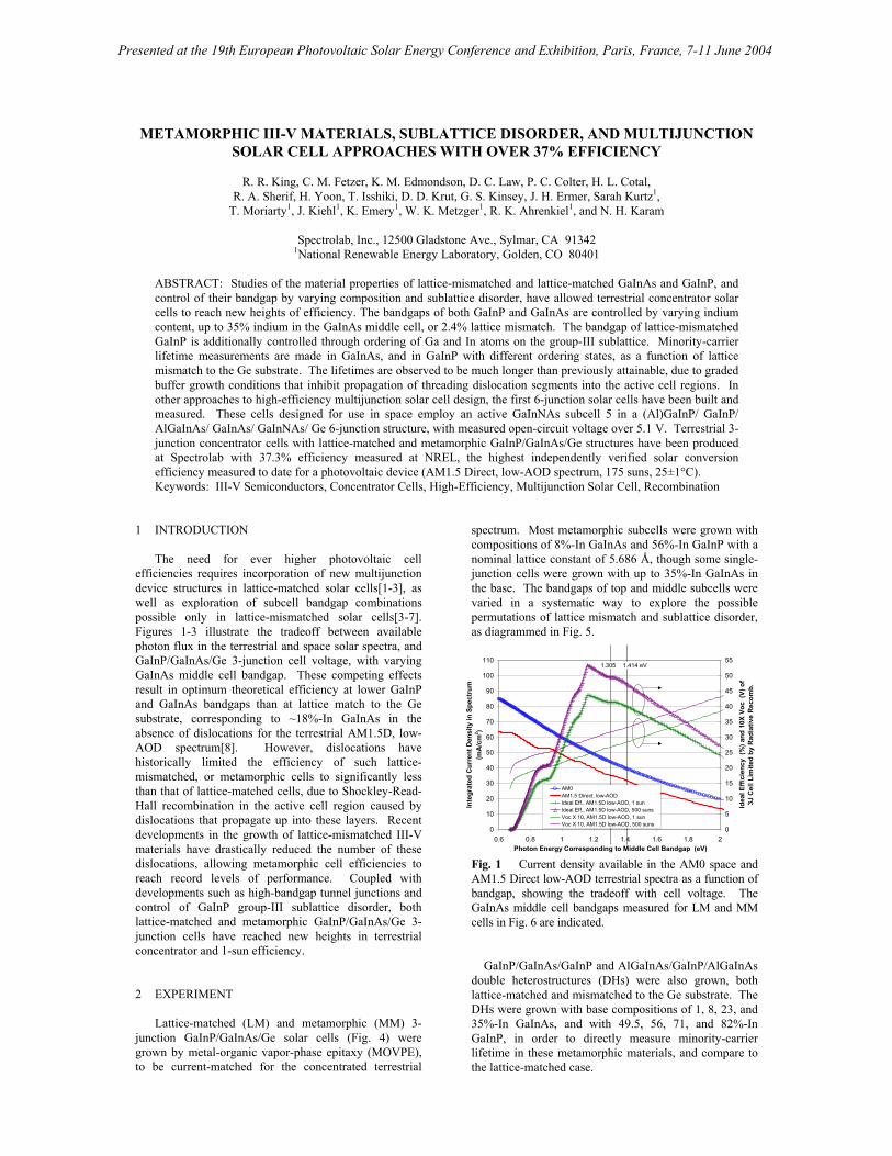
spectrum. Most metamorphic subcells were grown with compositions of 8%-In GaInAs and 56%-In GaInP with a nominal lattice constant of 5.686 Å, though some single-junction cells were grown with up to 35%-In GaInAs in the base. The bandgaps of top and middle subcells were varied in a systematic way to explore the possible permutations of lattice mismatch and sublattice disorder, as diagrammed in Fig. 5.
0
10
20
30
40
50
60
70
80
90
100
110
0.6 0.8 1 1.2 1.4 1.6 1.8 2Photon Energy Corresponding to Middle Cell Bandgap (eV)
Inte
grat
ed C
urre
nt D
ensi
ty in
Spe
ctru
m
(mA
/cm
2 )
0
5
10
15
20
25
30
35
40
45
50
55
Idea
l Effi
cien
cy (
%) a
nd 1
0X V
oc (
V) o
f3J
Cel
l Lim
ited
by R
adia
tive
Rec
omb.
AM0AM1.5 Direct, low-AODIdeal Eff., AM1.5D low-AOD, 1 sunIdeal Eff., AM1.5D low-AOD, 500 sunsVoc X 10, AM1.5D low-AOD, 1 sunVoc X 10, AM1.5D low-AOD, 500 suns
1.305 1.414 eV
Fig. 1 Current density available in the AM0 space and AM1.5 Direct low-AOD terrestrial spectra as a function of bandgap, showing the tradeoff with cell voltage. The GaInAs middle cell bandgaps measured for LM and MM cells in Fig. 6 are indicated. GaInP/GaInAs/GaInP and AlGaInAs/GaInP/AlGaInAs double heterostructures (DHs) were also grown, both lattice-matched and mismatched to the Ge substrate. The DHs were grown with base compositions of 1, 8, 23, and 35%-In GaInAs, and with 49.5, 56, 71, and 82%-In GaInP, in order to directly measure minority-carrier lifetime in these metamorphic materials, and compare to the lattice-matched case.
Presented at the 19th European Photovoltaic Solar Energy Conference and Exhibition, Paris, France, 7-11 June 2004

Ga0.515In0.495P /Ga0.99In0.01As 2J
Ga0.44In0.56P /Ga0.92In0.08As 2J
Ga0.29In0.71P /Ga0.77In0.23As 2J
Ga0.515In0.495P /Ga0.99In0.01As 2J
Ga0.44In0.56P /Ga0.92In0.08As 2J
Ga0.29In0.71P /Ga0.77In0.23As 2J
Ga0.515In0.495P /Ga0.99In0.01As 2J
Ga0.44In0.56P /Ga0.92In0.08As 2J
Ga0.29In0.71P /Ga0.77In0.23As 2J
Ga0.515In0.495P /Ga0.99In0.01As 2J
Ga0.44In0.56P /Ga0.92In0.08As 2J
Ga0.29In0.71P /Ga0.77In0.23As 2J
Ga0.515In0.495P /Ga0.99In0.01As 2J
Ga0.44In0.56P /Ga0.92In0.08As 2J
Ga0.29In0.71P /Ga0.77In0.23As 2J
Ga0.515In0.495P /Ga0.99In0.01As 2J
Ga0.44In0.56P /Ga0.92In0.08As 2J
Ga0.29In0.71P /Ga0.77In0.23As 2J
Fig. 2 Dual-junction cell efficiency contours for the AM0 space and AM1.5D terrestrial spectra, with the possible bandgap combinations for GaInP/GaInAs cells with varying indium composition and lattice-mismatch to a Ge substrate, for GaInP with a disordered (higher bandgap) or an ordered group-III sublattice.
22
24
26
28
30
32
34
36
5.64 5.66 5.68 5.7 5.72 5.74 5.76Lattice Constant (A)
Met
amor
phic
GaI
nP/G
aInA
s/G
e 3-
Junc
tion
Cel
l AM
0 Ef
ficie
ncy
(%)
Theoretical AM0 EfficiencyPractical AM0 EfficiencyExpt. 3J Cell Efficiency
GaA
s
8%-In
GaI
nAs
Fig. 3 Theoretical and experimental AM0 efficiencies for 3-junction GaInP/GaInAs/Ge solar cells as a function of lattice mismatch. The AM1.5G (E 892-87) [9] spectrum has been found by the National Renewable Energy Laboratory (NREL) to be a closer match than AM1.5D (E 891-87) [10] to the actual spectrum in most concentrator applications[11]. Recently, the AM1.5 Direct, low-AOD spectrum has been adopted by NREL as the standard reporting spectrum for concentrator cells[8]. The record concentrator cell efficiency results reported in this paper were independently verified under this spectrum at NREL.
Tunnel J
unction
Top Cell
Wide-Eg Tunnel
Middle Cell
p-GaInP BSF
p-GaInP base
n-Ga(In)As emitter
n+-Ge emitter
p-AlGaInP BSF
n-GaInP emittern-AlInP windown+-Ga(In)As
contact
AR
p-Ge baseand substratecontact
n-Ga(In)As buffer
Bottom Cell
p++-TJn++-TJ
p-Ga(In)As base
nucleation
Wide-bandgap tunnel junction
GaInP top cell
Ge bottom cell
n-GaInP window
p++-TJn++-TJ
Ga(In)As middle cell
Tunnel junction
Buffer region
Tunnel J
unction
Top Cell
Wide-Eg Tunnel
Middle Cell
p-GaInP BSF
p-GaInP base
n-Ga(In)As emitter
n+-Ge emitter
p-AlGaInP BSF
n-GaInP emittern-AlInP windown+-Ga(In)As
contact
AR
p-Ge baseand substratecontact
n-Ga(In)As buffer
Bottom Cell
p++-TJn++-TJ
p-Ga(In)As base
nucleation
Wide-bandgap tunnel junction
GaInP top cell
Ge bottom cell
n-GaInP window
p++-TJn++-TJ
Ga(In)As middle cell
Tunnel junction
Buffer regionTunnel
Juncti
on
Top Cell
Wide-Eg Tunnel
Middle Cell
p-GaInP BSF
p-GaInP base
n-GaInAs emitter
n+-Ge emitter
p-AlGaInP BSF
n-GaInP emittern-AlInP windown+-GaInAs
contact
AR
p-Ge baseand substratecontact
p-GaInAsstep-graded buffer
Bottom Cell
p++-TJn++-TJ
p-GaInAs base
nucleation
n-GaInP window
p++-TJn++-TJ
Tunnel Ju
nction
Top Cell
Wide-Eg Tunnel
Middle Cell
p-GaInP BSF
p-GaInP base
n-GaInAs emitter
n+-Ge emitter
p-AlGaInP BSF
n-GaInP emittern-AlInP windown+-GaInAs
contact
AR
p-Ge baseand substratecontact
p-GaInAsstep-graded buffer
Bottom Cell
p++-TJn++-TJ
p-GaInAs base
nucleation
n-GaInP window
p++-TJn++-TJ
Lattice-Matched (LM) Lattice-Mismatchedor Metamorphic (MM)
Fig. 4 Schematic cross-section of lattice-matched and metamorphic 3-junction cells. The metamorphic cell incorporates a buffer layer with graded composition to accommodate the mismatch, and suppress propagation of threading dislocations into the active cell layers above.
0.6
0.8
1
1.2
1.4
1.6
1.8
2
5.6 5.65 5.7 5.75 5.8
Lattice Constant (angstrom)
Dire
ct B
andg
ap E
g (e
V)
Ge(indirect)
GaAs
disordered GaInP
ordered GaInP
GaInAs8%-In GaInAs 12%-In
23%-In GaInAs
1%-In
35%-In
Fig. 5 Six middle subcell bandgaps and lattice constants, varied by altering indium composition (lattice constant), and 8 top cell bandgaps and lattice constants, varied by composition and group-III sublattice ordering in the GaInP, for the experimental conditions described in the text. External quantum efficiency (EQE) and room-temperature wavelength-resolved photoluminescence (PL) were measured for the LM and MM cells, to characterize subcell bandgap and minority-carrier collection properties. A 488 nm Ar ion laser was the excitation source for wavelength resolved PL. Minority-carrier lifetimes in the DHs were measured directly by time-resolved photoluminescence (TRPL) at NREL, using a rhodamine 6G dye laser at 580 nm, a multichannel plate photomultiplier tube, and an overall 30 ps response time. 3 RESULTS AND DISCUSSION 3.1 Metamorphic GaInAs and GaInP Materials The measured EQE of 3-junction LM and MM cells is shown in Figs. 6 and 7, with the photoluminescence spectra also plotted in Fig. 6. The energy of the PL peak, a reasonable estimate of the subcell bandgap Eg , is indicated in the figure. The shift of ~80 meV downward for the GaInP top cell, and ~110 meV for the GaInAs cell is readily apparent for the metamorphic case, resulting in higher available current density. The offset between bandgap voltage Eg/q and open-circuit voltage Voc of a
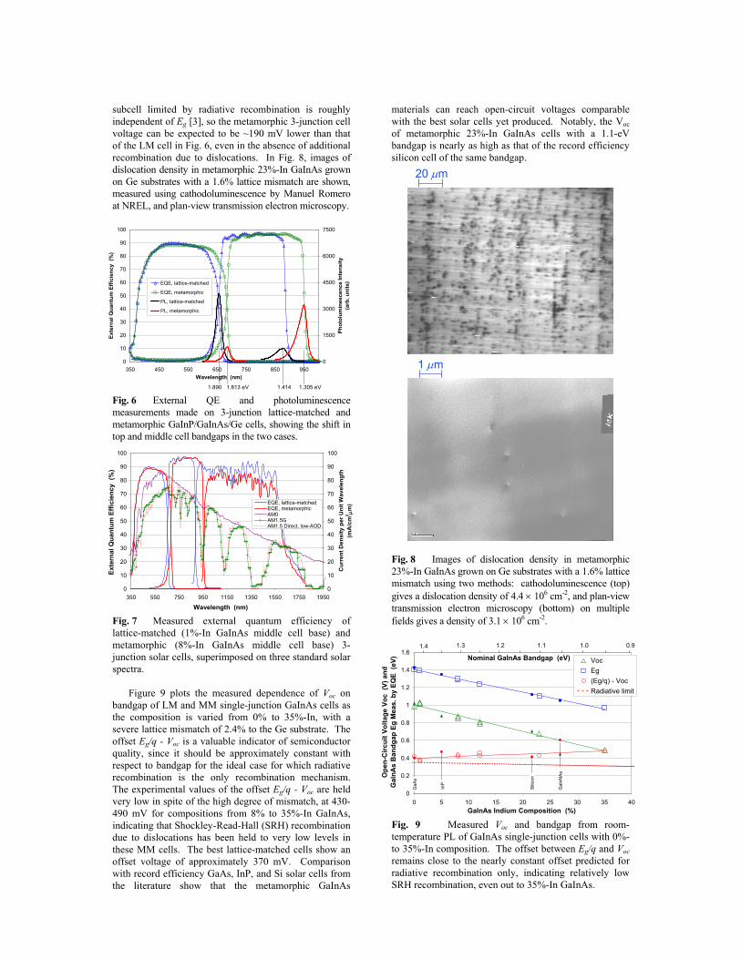
subcell limited by radiative recombination is roughly independent of Eg [3], so the metamorphic 3-junction cell voltage can be expected to be ~190 mV lower than that of the LM cell in Fig. 6, even in the absence of additional recombination due to dislocations. In Fig. 8, images of dislocation density in metamorphic 23%-In GaInAs grown on Ge substrates with a 1.6% lattice mismatch are shown, measured using cathodoluminescence by Manuel Romero at NREL, and plan-view transmission electron microscopy.
0
10
20
30
40
50
60
70
80
90
100
350 450 550 650 750 850 950Wavelength (nm)
Exte
rnal
Qua
ntum
Effi
cien
cy (
%)
0
1500
3000
4500
6000
7500
Phot
olum
ines
cenc
e In
tens
ity
(arb
. uni
ts)EQE, lattice-matched
EQE, metamorphic
PL, lattice-matched
PL, metamorphic
1.890 1.813 eV 1.414 1.305 eV Fig. 6 External QE and photoluminescence measurements made on 3-junction lattice-matched and metamorphic GaInP/GaInAs/Ge cells, showing the shift in top and middle cell bandgaps in the two cases.
0
10
20
30
40
50
60
70
80
90
100
350 550 750 950 1150 1350 1550 1750 1950
Wavelength (nm)
Exte
rnal
Qua
ntum
Effi
cien
cy (
%)
0
10
20
30
40
50
60
70
80
90
100
Cur
rent
Den
sity
per
Uni
t Wav
elen
gth
(mA
/cm
2 µm
)EQE, lattice-matchedEQE, metamorphicAM0AM1.5GAM1.5 Direct, low-AOD
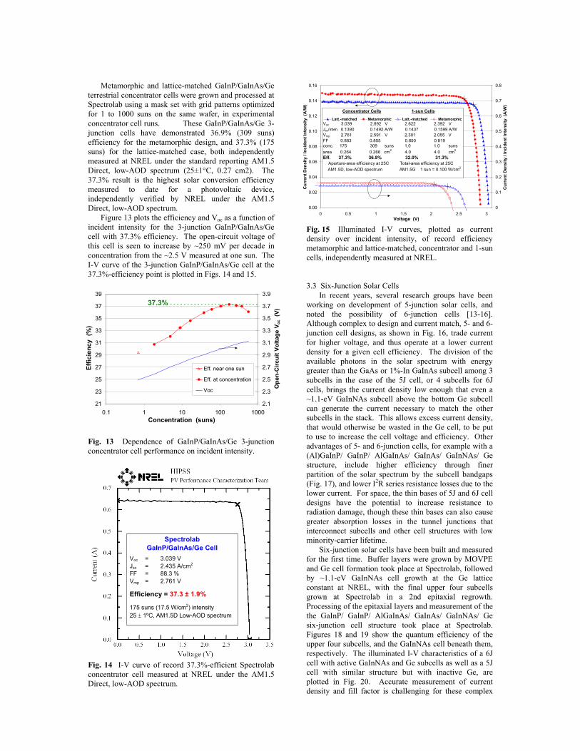
Fig. 7 Measured external quantum efficiency of lattice-matched (1%-In GaInAs middle cell base) and metamorphic (8%-In GaInAs middle cell base) 3-junction solar cells, superimposed on three standard solar spectra. Figure 9 plots the measured dependence of Voc on bandgap of LM and MM single-junction GaInAs cells as the composition is varied from 0% to 35%-In, with a severe lattice mismatch of 2.4% to the Ge substrate. The offset Eg/q - Voc is a valuable indicator of semiconductor quality, since it should be approximately constant with respect to bandgap for the ideal case for which radiative recombination is the only recombination mechanism. The experimental values of the offset Eg/q - Voc are held very low in spite of the high degree of mismatch, at 430-490 mV for compositions from 8% to 35%-In GaInAs, indicating that Shockley-Read-Hall (SRH) recombination due to dislocations has been held to very low levels in these MM cells. The best lattice-matched cells show an offset voltage of approximately 370 mV. Comparison with record efficiency GaAs, InP, and Si solar cells from the literature show that the metamorphic GaInAs
materials can reach open-circuit voltages comparable with the best solar cells yet produced. Notably, the Voc of metamorphic 23%-In GaInAs cells with a 1.1-eV bandgap is nearly as high as that of the record efficiency silicon cell of the same bandgap.
20 µm
1 µm
Fig. 8 Images of dislocation density in metamorphic 23%-In GaInAs grown on Ge substrates with a 1.6% lattice mismatch using two methods: cathodoluminescence (top) gives a dislocation density of 4.4 × 106 cm-2, and plan-view transmission electron microscopy (bottom) on multiple fields gives a density of 3.1 × 106 cm-2.
0
0.2
0.4
0.6
0.8
1
1.2
1.4
1.6
0 5 10 15 20 25 30 35 40GaInAs Indium Composition (%)
Ope
n-C
ircui
t Vol
tage
Voc
(V)
and
G
aInA
s B
andg
ap E
g M
eas.
by
EQE
(eV) Voc
Eg(Eg/q) - VocRadiative limit
Nominal GaInAs Bandgap (eV)1.4 0.91.01.11.21.3
GaA
s
Silic
on
InP
GaI
nNAs
Fig. 9 Measured Voc and bandgap from room-temperature PL of GaInAs single-junction cells with 0%- to 35%-In composition. The offset between Eg/q and Voc remains close to the nearly constant offset predicted for radiative recombination only, indicating relatively low SRH recombination, even out to 35%-In GaInAs.

The dependence of SRH recombination on lattice mismatch in these metamorphic materials is shown in Fig. 10, by plotting the minority-carrier lifetime measured by TRPL in GaInAs- and GaInP-base double heterostructures. The effective lifetime shown is a lower limit for the bulk lifetime in the base material. Measured lifetimes are shown for recent measurements of not-intentionally-doped (nid) GaInAs DHs with 1%, 8%, 23%, and 35%-In GaInAs base compositions and p-type GaInP DHs grown with the same amount of lattice mismatch to the Ge substrate as these GaInAs compositions. For comparison, DH lifetimes are shown for GaInP with an ordered group-III sublattice (lower bandgap than disordered for a given GaInP composition), GaInP with a disordered sublattice (higher bandgap), and GaInAs bases from previous work[3]. The recent TRPL lifetime data show a phenomenally long lifetime of 600 ns in the metamorphic Ga0.92In0.08As base, compared to 1120 ns in the lattice-matched Ga0.99In0.01As case. The measured lifetime in these recent metamorphic Ga0.92In0.08As samples is approximately 60 times longer than in earlier MM 8%-In GaInAs DHs. For the highly lattice-mismatched compositions of 23% and 35%-In GaInAs bases, lifetimes of over 10 ns were measured (the lifetimes plotted are at the beginning of the carrier decay curve, before detrapping effects have much effect). These lifetimes are nearly the same as for GaAs (0%-In) DHs on Ge, in spite of the much more extreme lattice mismatch to the Ge substrate for the 23% and 35%-In GaInAs samples.
0.1
1
10
100
1000
10000
0 5 10 15 20 25 30 35Indium Mole Fraction of GaInAs Lattice-Matched to Base (%)
τ eff
Mea
sure
d by
TR
PL (
ns)
Base MaterialRecent data nid-GaInAs, recent data p-GaInP (disordered)Previous data nid-GaInAs nid-GaInP (ordered) nid-GaInP (disordered)
Eg = 1.407 eV
1.813 eV
1.887 eV 1.311 eV
1.736 eV
1.807 eV
1.114 eV
1.619 eV
0.994 eV
1.529 eV
Fig. 10 Minority-carrier lifetime in LM and MM double heterostructures with GaInAs and GaInP bases, showing the very high lifetimes achieved out to 35%-In GaInAs. 3.2 Three-Junction Solar Cell Results Three-junction GaInP/GaInAs/Ge cells were grown with varying bandgap combinations in the top and middle cells, by exploring both metamorphic and lattice-matched GaInP top cells at the lattice constant of 8%-In and 1%-In GaInAs, respectively, and by growing both ordered and disordered GaInP at each of these lattice constants. Additionally, ordered GaInP top cells were grown at the lattice constant of a 23%-In GaInAs subcell 2 in two-junction cells. The thickness of the top cell base was adjusted to achieve approximate current matching between the top two subcells of varying bandgap. A bandgap reduction in partially ordered GaInP compared
to GaInP with a disordered group-III sublattice was seen not only in the 49.5%-In GaInP case lattice-matched to the Ge substrate, but was observed to persist in partially ordered 56%-In GaInP and 71%-In GaInP, at lattice mismatches of 0.5% and 1.6%, respectively, compared to disordered GaInP at each composition. The ordering state was quantified directly using XRD measurements of the ½(115) ordering peak at each composition, and the bandgap was measured by photoluminescence. Light I-V measurements were calibrated by the integrated current density for the AM0 spectrum from external QE measurements made on each subcell. The cells in this study had no AR coating, but the active-area efficiency was found from bare cell measurements correcting for the reduced reflectance measured on companion AR coated cells, and for the grid shadowing. Measurements of the 71%-In GaInP/ 23%-GaInAs two-junction cells were used to project the performance of a 3J cell with the same two top cells, for comparison. The 3J cell efficiency and Voc are plotted vs. the GaInAs indium composition (lattice constant), and the nominal bandgap of the GaInP top cell in Fig. 11. Voc can be seen to be highest for the 3-junction cell with the highest bandgap GaInP top cells, and the measured cell efficiency also follows this trend. AM0 efficiencies up to 30.5% have been measured on fully-processed 4 cm2 cells at Spectrolab, as shown in Fig. 12.
1%-In
8%-In
23%
-In1.9
1.81.7
1.6
1.5
10
12
14
16
18
20
22
24
26
28
30
32
3J C
ell A
pert
ure-
Are
a E
ff.
(%)
and
Voc
X 1
0 (V
)
% In in GaInAs
Nominal Bandgap
(eV)
3J Eff. -- disord. GaInP 3J Voc -- disord. GaInP 3J Eff. -- ordered GaInP 3J Voc -- ordered GaInP
Fig. 11 Measured 3-junction cell AM0 efficiency and open-circuit voltage for 5 experimental combinations of top and middle cell bandgaps, based on GaInAs and GaInP compositions, and GaInP top cell ordering state.
0
2
4
6
8
10
12
14
16
18
20
0.0 0.5 1.0 1.5 2.0 2.5 3.0
Voltage (V)
Cur
rent
Den
sity
(m
A/c
m2 )
Glassed 2x2 MgF2 coated
Voc 2.698 V 2.703 V Jsc 17.72 mA/cm2 17.88 mA/cm2
FF 85.4 % 85.4 % Vmp 2.381 V 2.387 V
Eff. 30.16 % 30.52 %
(AM0, 0.1353 W/cm2, 4.0 cm2, 28oC)
Fig. 12 Illuminated I-V curves for AR coated 2 cm × 2 cm cells with AM0 efficiency up to 30.5%.
Metamorphic and lattice-matched GaInP/GaInAs/Ge terrestrial concentrator cells were grown and processed at Spectrolab using a mask set with grid patterns optimized for 1 to 1000 suns on the same wafer, in experimental concentrator cell runs. These GaInP/GaInAs/Ge 3-junction cells have demonstrated 36.9% (309 suns) efficiency for the metamorphic design, and 37.3% (175 suns) for the lattice-matched case, both independently measured at NREL under the standard reporting AM1.5 Direct, low-AOD spectrum (25±1°C, 0.27 cm2). The 37.3% result is the highest solar conversion efficiency measured to date for a photovoltaic device, independently verified by NREL under the AM1.5 Direct, low-AOD spectrum. Figure 13 plots the efficiency and Voc as a function of incident intensity for the 3-junction GaInP/GaInAs/Ge cell with 37.3% efficiency. The open-circuit voltage of this cell is seen to increase by ~250 mV per decade in concentration from the ~2.5 V measured at one sun. The I-V curve of the 3-junction GaInP/GaInAs/Ge cell at the 37.3%-efficiency point is plotted in Figs. 14 and 15.
21
23
25
27
29
31
33
35
37
39
0.1 1 10 100 1000Concentration (suns)
Effic
ienc
y (%
)
2.1
2.3
2.5
2.7
2.9
3.1
3.3
3.5
3.7
3.9
Ope
n-C
ircui
t Vol
tage
Voc
(V)
Eff. near one sun
Eff. at concentration
Voc
37.3%
Fig. 13 Dependence of GaInP/GaInAs/Ge 3-junction concentrator cell performance on incident intensity.
Spectrolab GaInP/GaInAs/Ge Cell
Voc = 3.039 V Jsc = 2.435 A/cm2 FF = 88.3 % Vmp = 2.761 V
Efficiency = 37.3 ± 1.9%
175 suns (17.5 W/cm2) intensity 25 ± 1ºC, AM1.5D Low-AOD spectrum
Fig. 14 I-V curve of record 37.3%-efficient Spectrolab concentrator cell measured at NREL under the AM1.5 Direct, low-AOD spectrum.
0.00
0.02
0.04
0.06
0.08
0.10
0.12
0.14
0.16
0 0.5 1 1.5 2 2.5 3Voltage (V)
Cur
rent
Den
sity
/ In
cide
nt In
tens
ity (
A/W
)
0
0.1
0.2
0.3
0.4
0.5
0.6
0.7
0.8
Cur
rent
Den
sity
/ In
cide
nt In
tens
ity (
A/W
)
Latt.-matched Metamorphic Latt.-matched MetamorphicVoc 3.039 2.892 V 2.622 2.392 V Jsc/inten. 0.1390 0.1492 A/W 0.1437 0.1599 A/W Vmp 2.761 2.591 V 2.301 2.055 V FF 0.883 0.855 0.850 0.819conc. 175 309 suns 1.0 1.0 sunsarea 0.264 0.266 cm2 4.0 4.0 cm2
Eff. 37.3% 36.9% 32.0% 31.3% Aperture-area efficiency at 25C Total-area efficiency at 25C AM1.5D, low-AOD spectrum AM1.5G 1 sun = 0.100 W/cm2
Concentrator Cells 1-sun Cells
Fig. 15 Illuminated I-V curves, plotted as current density over incident intensity, of record efficiency metamorphic and lattice-matched, concentrator and 1-sun cells, independently measured at NREL. 3.3 Six-Junction Solar Cells In recent years, several research groups have been working on development of 5-junction solar cells, and noted the possibility of 6-junction cells [13-16]. Although complex to design and current match, 5- and 6-junction cell designs, as shown in Fig. 16, trade current for higher voltage, and thus operate at a lower current density for a given cell efficiency. The division of the available photons in the solar spectrum with energy greater than the GaAs or 1%-In GaInAs subcell among 3 subcells in the case of the 5J cell, or 4 subcells for 6J cells, brings the current density low enough that even a ~1.1-eV GaInNAs subcell above the bottom Ge subcell can generate the current necessary to match the other subcells in the stack. This allows excess current density, that would otherwise be wasted in the Ge cell, to be put to use to increase the cell voltage and efficiency. Other advantages of 5- and 6-junction cells, for example with a (Al)GaInP/ GaInP/ AlGaInAs/ GaInAs/ GaInNAs/ Ge structure, include higher efficiency through finer partition of the solar spectrum by the subcell bandgaps (Fig. 17), and lower I2R series resistance losses due to the lower current. For space, the thin bases of 5J and 6J cell designs have the potential to increase resistance to radiation damage, though these thin bases can also cause greater absorption losses in the tunnel junctions that interconnect subcells and other cell structures with low minority-carrier lifetime. Six-junction solar cells have been built and measured for the first time. Buffer layers were grown by MOVPE and Ge cell formation took place at Spectrolab, followed by ~1.1-eV GaInNAs cell growth at the Ge lattice constant at NREL, with the final upper four subcells grown at Spectrolab in a 2nd epitaxial regrowth. Processing of the epitaxial layers and measurement of the the GaInP/ GaInP/ AlGaInAs/ GaInAs/ GaInNAs/ Ge six-junction cell structure took place at Spectrolab. Figures 18 and 19 show the quantum efficiency of the upper four subcells, and the GaInNAs cell beneath them, respectively. The illuminated I-V characteristics of a 6J cell with active GaInNAs and Ge subcells as well as a 5J cell with similar structure but with inactive Ge, are plotted in Fig. 20. Accurate measurement of current density and fill factor is challenging for these complex

structures, and will require further hardware modification to solar simulators used for multijunction cell testing, but confidence in the Voc measured is quite high even in these preliminary I-V measurements. Open-circuit voltages as high as 5.11 V were measured for these first prototype 6-junction cells.
cap
contactAR
(Al)GaInP Cell 1 2.0 eVwide-Eg tunnel junction
AlGa(In)As Cell 21.7 eV
tunnel junction
Ga(In)As Cell 31.41 eV
tunnel junction
AR
Ga(In)As buffer
Ge Cell 5and substrate
0.67 eV
nucleation
back contact
wide-Eg tunnel junction
GaInNAs Cell 41.1 eV
cap
contactAR
(Al)GaInP Cell 1 2.0 eVwide-Eg tunnel junction
AlGa(In)As Cell 21.7 eV
tunnel junction
Ga(In)As Cell 31.41 eV
tunnel junction
AR
Ga(In)As buffer
Ge Cell 5and substrate
0.67 eV
nucleationnucleation
back contact
wide-Eg tunnel junction
GaInNAs Cell 41.1 eV
cap
contactAR
(Al)GaInP Cell 1 2.0 eVwide-Eg tunnel junction
GaInP Cell 2 (low Eg)1.8 eV
wide-Eg tunnel junction
AlGa(In)As Cell 31.6 eV
tunnel junction
Ga(In)As Cell 41.41 eV
tunnel junction
AR
Ga(In)As buffer
Ge Cell 6and substrate
0.67 eV
nucleation
back contact
wide-Eg tunnel junction
GaInNAs Cell 51.1 eV
cap
contactAR
(Al)GaInP Cell 1 2.0 eVwide-Eg tunnel junction
GaInP Cell 2 (low Eg)1.8 eV
wide-Eg tunnel junction
AlGa(In)As Cell 31.6 eV
tunnel junction
Ga(In)As Cell 41.41 eV
tunnel junction
AR
Ga(In)As buffer
Ge Cell 6and substrate
0.67 eV
nucleationnucleation
back contact
wide-Eg tunnel junction
GaInNAs Cell 51.1 eV
5-junction 6-junction Fig. 16 Schematic cross-sections of 5-junction and 6-junction solar cells.
0
10
20
30
40
50
60
70
80
90
100
350 550 750 950 1150 1350 1550 1750 1950
Wavelength (nm)
0
10
20
30
40
50
60
70
80
90
100
Cur
rent
Den
sity
per
Uni
t Wav
elen
gth
(mA
/cm
2m
)
AM0
AM1.5G
AM1.5 Direct, low-AOD
1.41 eV 0.67 eV1.8 1.1 eV2.0 1.6
Fig. 17 Division of standard solar spectra by the bandgaps of the 6 subcells in a 6-junction cell.
Full Process (AR Coated) Top 4 Junctions of 6J Cell
0
10
20
30
40
50
60
70
80
90
100
350 450 550 650 750 850 950Wavelength (nm)
Exte
rnal
Qun
atum
Effi
cien
cy (%
)
AM0 Jsc (mA/cm2)Cell 1 = 9.05 mA/cm2
Cell 2 = 8.97 mA/cm2
Cell 3 = 8.27 mA/cm2
Cell 4 = 8.36 mA/cm2
Fig. 18 External quantum efficiency measurements of the upper 4 subcells of a 6-junction cell.
0
10
20
30
40
50
60
70
80
90
100
800 900 1000 1100 1200Wavelength (nm)
Qua
ntum
Effi
cien
cy (
%)
Low DMH GaInNAs in 6J cell Jsc = 1.93 mA/cm2 Eg = 1.17 eVMedium DMH GaInNAs in 6J cell Jsc = 2.53 mA/cm2 Eg = 1.11 eVHigh DMH GaInNAs in 6J cell Jsc = 3.14 mA/cm2 Eg = 1.09 eVGaInNAs in 5J structure from 2001 Jsc = 5.75 mA/cm2GaInNAs single-junction cell, int. QE Jsc = 11.2 mA/cm2
External QEno AR coat
Internal QESingle-junction
Fig. 19 QE measurements of the GaInNAs subcell 5 of a 6-junction solar cell, grown lattice-matched to the Ge substrate, and with a bandgap of ~1.1 eV.
0
1
2
3
4
5
6
0 1 2 3 4 5 6Voltage (V)
Cur
rent
Den
sity
(m
A/c
m2 )
6-junction GaInP/ GaInP/ AlGaInAs/ GaInAs/ GaInNAs/ Ge cell
5-junction GaInP/ GaInP/ AlGaInAs/ GaInAs/ GaInNAs cell on Ge
6-Junction 5-Junction
Voc 5.11 V 4.81 VJsc 4.80 mA/cm2 4.89 mA/cm2
FF 74.3 % 75.5 %Vmp 4.46 V 4.16 VEff. 13.47 % 13.13%Area 0.2584 cm2 0.2516 cm2
Preliminary light I-V meas., no AR coating
Fig. 20 Light I-V measurements of the first 6-junction cells demonstrated. These 6J cells have active GaInNAs and Ge subcells, and open-circuit voltage over 5 volts. 4 SUMMARY Recent developments in epitaxial III-V multijunction solar cell technology have allowed terrestrial concentrator cells to reach new heights in efficiency under the terrestrial solar spectrum. The bandgaps of the component GaInP and GaInAs subcells of GaInP/ GaInAs/ Ge 3-junction cells were varied in experiments by controlling the degree of lattice mismatch with respect to the substrate, and by varying the amount of Ga and In ordering on the group-III sublattice in GaInP. Minority-carrier lifetime was measured by TRPL in GaInP- and GaInAs-base double heterostructures (DHs) with a range of lattice mismatch and sublattice disordering conditions. Shockley-Read-Hall recombination at dislocations in such metamorphic cells has been restricted to far lower levels than previously achieved. The threading dislocation density in metamorphic GaInAs grown on Ge substrates has been held to a low enough level that minority-carrier lifetime in 23%-In and 35%-In GaInAs DHs, with a lattice-mismatch up to 2.4%, is now similar to that in GaAs (0%-In) grown on Ge, at around 10 ns. Metamorphic 23%-In GaInAs single-junction cells with 1.1 eV bandgap have been measured with open-circuit voltage nearly as high as for record efficiency silicon solar cells with the same bandgap. Single-exponential decay of excess carriers in 8%-In GaInAs has been

observed with 600 ns lifetime, nearly as long as the lifetime in perfectly lattice-matched 1%-In GaInAs DHs on Ge. Group-III sublattice ordering has been directly observed in metamorphic GaInP, at compositions matched to 8%-In and 23%-In GaInAs by measurement of the ½(115) ordering peak, and the bandgap reduction due to ordering was quantified for these materials with a lattice-mismatch of 0.5% and 1.6% to the Ge substrate, respectively. The theoretical efficiency of GaInP/ GaInAs/ Ge 3-junction solar cells is predicted to be highest with ~18%-In GaInAs, and with disordered, high-bandgap GaInP subcells. These high-lifetime GaInP and GaInAs materials, with bandgaps varied using lattice mismatch and disorder, were incorporated in multijunction cells to study the tradeoffs between subcell thickness, bandgap, and current matching between subcells, and to compare theoretical performance with experiment. In other approaches to high-efficiency multijunction solar cell design, the first 6-junction solar cells have been built and measured. These cells designed for use in space employ an active GaInNAs subcell 5 in a (Al)GaInP/ GaInP/ AlGaInAs/ GaInAs/ GaInNAs/ Ge 6-junction structure, with measured Voc over 5.1 V. Terrestrial 3-junction concentrator cells with both metamorphic and lattice-matched GaInP/GaInAs/Ge structure have been produced at Spectrolab, with 36.9% efficiency for the metamorphic cell, and 37.3% for the lattice-matched case, both independently measured at NREL (AM1.5 Direct, low-AOD spectrum, 25±1°C, 0.27 cm2). The 37.3% efficiency result, at 175 suns, is the highest solar conversion efficiency measured to date for a photovoltaic device, as independently verified at NREL under the AM1.5 Direct, low-AOD spectrum. The efficiencies of the highest performance lattice-matched and metamorphic multijunction solar cells are approaching parity, opening the gate to a new territory of multijunction device design parameters yielding still higher photovoltaic cell performance. ACKNOWLEDGMENTS The authors would like to thank Donna Senft and Henry Yoo at the Air Force Research Lab; Martha Symko-Davies, Brian Keyes, Manuel Romero, Dan Friedman, and Jerry Olson at NREL; and David Joslin, Warren Nishikawa, Mark Takahashi, and Greg Glenn, and the entire multijunction solar cell team at Spectrolab. This work was supported in part by the Air Force Research Laboratory (AFRL/VS) under DUS&T contract # F29601-98-2-0207, by the Dept. of Energy through the NREL High-Performance PV program (NAT-1-30620-01), and by Spectrolab. REFERENCES [1] J. Olson, S. Kurtz, A. Kibbler, and P. Faine, "A 27.3% Efficient Ga0.5In0.5P/GaAs Tandem Solar Cell," Appl. Phys. Lett., 56, p.623 (1990). [2] T. Takamoto, T. Agui, K. Kamimura, M. Kaneiwa, M. Imaizumi, S. Matsuda, M. Yamaguchi, "Multijunction Solar Cell Technologies – High-Efficiency, Radiation Resistance, and Concentrator Applications," 3rd World Conf. on Photovoltaic Energy Conv. (WCPEC), Osaka, Japan, 11-18 May 2003, pp. 581-586.
[3] R. R. King, C. M. Fetzer, P. C. Colter, K. M. Edmondson, J. H. Ermer, H. L. Cotal, H. Yoon, A. P. Stavrides, G. Kinsey, D. D. Krut, N. H. Karam, "High-Efficiency Space and Terrestrial Multijunction Solar Cells Through Bandgap Control in Cell Structures," Proc. 29th IEEE Photovoltaic Specialists Conf. (PVSC), 19-24 May 2002, pp. 776-781. [4] R. R. King, M. Haddad, T. Isshiki, P. C. Colter, J. H. Ermer, H. Yoon, D. E. Joslin, and N. H. Karam, "Metamorphic GaInP/GaInAs/Ge Solar Cells," Proc. 28th IEEE PVSC, 15-22 Sept. 2000, p. 982-985. [5] F. Dimroth, U. Schubert, and A. W. Bett, "25.5% Efficient Ga0.35In0.65P/Ga0.83In0.17As Tandem Solar Cells Grown on GaAs Substrates," IEEE Electron Device Lett., 21, p. 209 (2000). [6] R. R. King, C. M. Fetzer, P. C. Colter, K. M. Edmondson, D. C. Law, A. P. Stavrides, H. Yoon, G. S. Kinsey, H. L. Cotal, J. H. Ermer, R. A. Sherif, K. Emery, W. Metzger, R. K. Ahrenkiel, and N. H. Karam, "Lattice-Matched and Metamorphic GaInP/GaInAs/Ge Concentrator Solar Cells," 3rd WCPEC., Osaka, Japan, 11-18 May 2003, pp. 622-625. [7] C. M. Fetzer, R. R. King, P. C. Colter, K. M. Edmondson, D. C. Law, A. P. Stavrides, H. Yoon, J. H. Ermer, M. J. Romero, N. H. Karam, “High-efficiency metamorphic GaInP/GaInAs/Ge solar cells grown by MOVPE”, J. Cryst. Growth, 261 (2004), p. 341. [8] K. Emery, D. Meyers, and Sarah Kurtz, "What is the Appropriate Reference Spectrum for Characterizing Concentrator Cells?," Proc. 29th IEEE PVSC, 19-24 May 2002, pp. 840-843. [9] Standard ASTM 892-92, Standard for Terrestrial Solar Spectral Irradiance Tables at Air Mass 1.5 for a 37° Tilted Surface (Amer. Society for Testing Matls., West Conshocken, PA, USA). [10] Standard ASTM 891-92, Standard for Terrestrial Solar Direct Normal Solar Spectral Irradiance Tables for Air Mass 1.5 (Amer. Society for Testing Matls., West Conshocken, PA, USA). [11] K. Emery, "What is the Appropriate Reference Condition for Determining the Efficiency?," NCPV Program Review Mtg. (AIP Press, Woodbury,NY, 2001). [12] M. A. Green, K. Emery, D. L. King, S. Igari, W. Warta, "Solar Cell Efficiency Tables (Version 23)," Prog. in Photovoltaics: Res. Appl., 12, pp. 55-62 (2004). [13] R. R. King, D. E. Joslin, N. H. Karam, “Multijunction Photovoltaic Cell with Thin 1st (Top) Subcell and Thick 2nd Subcell of Same or Similar Semiconductor Material,” U.S. Patent No. 6,316,715, filed Mar. 15, 2000, issued Nov. 13, 2001. [14] F. Dimroth, U. Schubert, A. W. Bett, J. Hilgarth, M. Nell, G. Strobl, K. Bogus, C. Signorini, “Next Generation GaInP/GaInAs/Ge Multi-junction Space Solar Cells,” 17th European Photovoltaic Solar Energy Conf., Munich, Germany, 22-26 Oct. 2001. [15] R. R. King, P. C. Colter, D. E. Joslin, K. M. Edmondson, D. D. Krut, N. H. Karam, and Sarah Kurtz, "High-Voltage, Low-Current GaInP/ GaInP/ GaAs/ GaInNAs/ Ge Solar Cells," 29th IEEE PVSC, 19-24 May 2002, pp. 852-855. [16] F. Dimroth, C. Baur, M. Meusel, S. van Riesen, and A. W. Bett, "5-Junction III-V Solar Cells for Space Applications," 3rd WCPEC, Osaka, Japan, 11-18 May 2003, pp. 616-621.