Embed Size (px)
Citation preview
MetalsPart 1
Manufacturing Processes, 1311
Dr Simin Nasseri
Southern Polytechnic State University
Manufacturing ProcessesProf Simin Nasseri
Four Types of Engineering Materials
1. Metals
2. Ceramics
3. Polymers
4. Composites
Manufacturing ProcessesProf Simin Nasseri
METALS
1. Alloys and Phase Diagrams
2. Ferrous Metals
3. Nonferrous Metals
4. Superalloys
5. Guide to the Processing of Metals
Manufacturing ProcessesProf Simin Nasseri
Why Metals Are Important
High stiffness and strength ‑ can be alloyed for
high rigidity, strength, and hardness
Toughness ‑ capacity to absorb energy better than
other classes of materials
Good electrical conductivity ‑ Metals are conductors
Good thermal conductivity ‑ conduct heat better than ceramics or polymers
Cost – the price of steel is very competitive with other engineering materials
Manufacturing ProcessesProf Simin Nasseri
Starting Forms of Metals used in Manufacturing Processes
Cast metal - starting form is a casting
Wrought metal - the metal has been worked or can be worked after casting
Powdered metal - starting form is very small powders for conversion into parts using powder metallurgy techniques
Manufacturing ProcessesProf Simin Nasseri
Classification of Metals
Ferrous ‑ those based on iron Steels Cast irons
Nonferrous ‑ all other metals Aluminum, magnesium, copper, nickel,
titanium, zinc, lead, tin, molybdenum, tungsten, gold, silver, platinum, and others
Superalloys

Manufacturing ProcessesProf Simin Nasseri
Metals and Alloys
An Alloy = A metal composed of two or more elements At least one element is metallic
Enhanced properties versus pure metals Strength Hardness Corrosion resistance
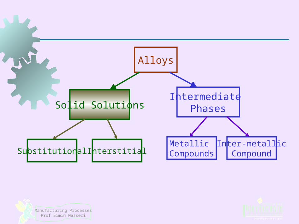
Two main categories Solid Solutions Intermediate Phases
Manufacturing ProcessesProf Simin Nasseri
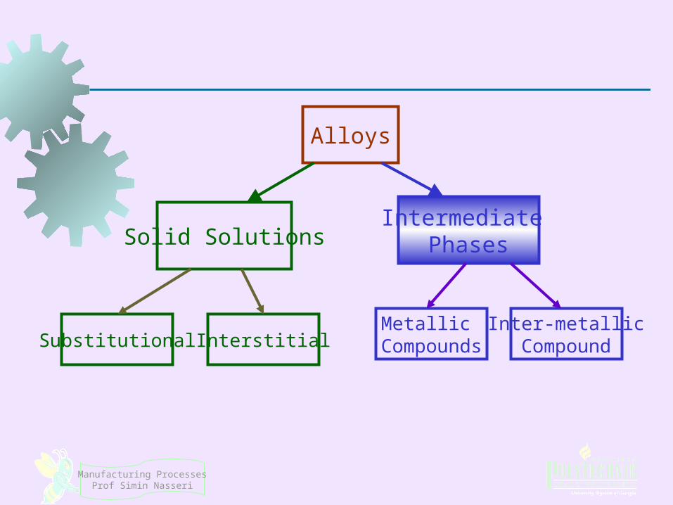
Alloys
Solid SolutionsIntermediate
Phases
Substitutional InterstitialMetallic
CompoundsInter-metallicCompound

Manufacturing ProcessesProf Simin Nasseri
An alloy in which one element is dissolved in another to form a single‑phase structure
Base element is metallic (Solvent) Dissolved element, metallic or non-metal
Solid Solutions
A phase = any homogeneous mass of material, such as a metal, in which the grains all have
the same crystal lattice structure!
What is a phase (in a material structure)?
Manufacturing ProcessesProf Simin Nasseri
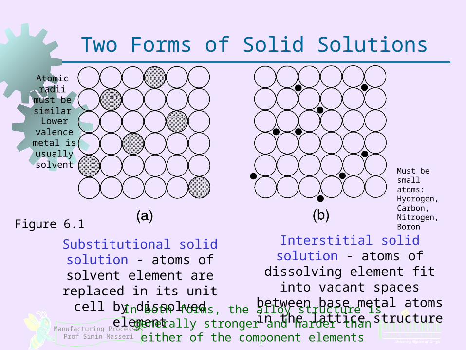
Two Forms of Solid Solutions
Substitutional solid solution - atoms of solvent element are replaced in its unit cell by dissolved element
Interstitial solid solution - atoms of dissolving element fit into vacant spaces between base metal atoms in the lattice
structure
In both forms, the alloy structure is generally stronger and harder than either of the component elements
Figure 6.1
Atomic radii must be similar
Lower valence metal is usually solvent
Must be small atoms:Hydrogen, Carbon, Nitrogen, Boron

Manufacturing ProcessesProf Simin Nasseri
Two Forms of Solid Solutions
Substitutional solid solution
Zinc dissolved in Copper = ??
Interstitial solid solution
Carbon dissolved in Iron = ??
Figure 6.1
BrassBrass SteelSteel
Manufacturing ProcessesProf Simin Nasseri
Alloys
Solid SolutionsIntermediate
Phases
Substitutional InterstitialMetallic
CompoundsInter-metallicCompound
Manufacturing ProcessesProf Simin Nasseri
Intermediate Phases
There are usually limits to the solubility of one element in another
When the amount of the dissolving element in the alloy exceeds the solid solubility limit of the base metal, a second phase forms in the alloy
The term intermediate phase is used to describe it because its chemical composition is intermediate between the two pure elements
Its crystalline structure is also different from those of the pure metals
Manufacturing ProcessesProf Simin Nasseri
Types of Intermediate Phases
1. Metallic compounds – consist of a metal and nonmetal, such as Fe3C
2. Intermetallic compounds ‑ two metals that form a compound, such as Mg2Pb
In some alloy compositions, the intermediate phase is mixed with the primary solid solution to form a two‑phase structure
Some two‑phase alloys are important because they can be heat treated for much higher strength than solid solutions
Phase Diagrams
Manufacturing ProcessesProf Simin Nasseri
Phase Diagrams
A graphical picture showing the phases of a metal alloy system as a function of composition and temperature
A phase diagram for an alloy system consisting of two elements at atmospheric pressure is called a binary phase diagram
Composition is plotted on the horizontal axis and temperature on the vertical axis
Any point in the diagram indicates the overall composition and the phase or phases present at the given temperature under equilibrium conditions
Manufacturing ProcessesProf Simin Nasseri
Copper-Nickel (Cu- Ni) Phase Diagram
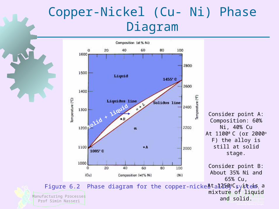
Figure 6.2 Phase diagram for the copper‑nickel alloy system.
solid + liquid Consider point A:
Composition: 60% Ni, 40% CuAt 11000 C (or 2000o F) the alloy is still at solid stage.
Consider point B:About 35% Ni and 65% Cu,At 1250oC, it is a mixture of
liquid and solid.
Manufacturing ProcessesProf Simin Nasseri
Chemical Compositions of Phases
The overall composition of the alloy is given by its position along the horizontal axis
However, the compositions of liquid and solid phases are not the same These compositions can be found by
drawing a horizontal line at the temperature of interest
Where the line intersects the solidus and liquidus indicates the compositions of solid and liquid phases, respectively. We use the Inverse Lever Rule to find the compositions:
Manufacturing ProcessesProf Simin Nasseri
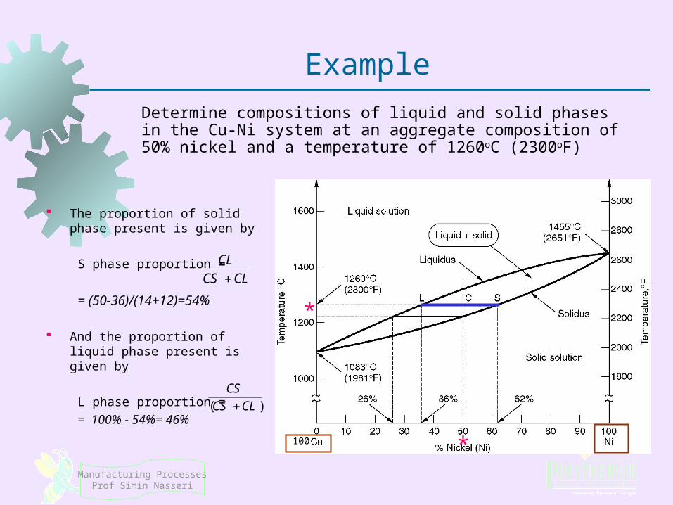
Example
Determine compositions of liquid and solid phases in the Cu-Ni system at an aggregate composition of 50% nickel and a temperature of 1260oC (2300oF)
The proportion of solid phase present is given by
S phase proportion =
= (50-36)/(14+12)=54%
And the proportion of liquid phase present is given by
L phase proportion =
= 100% - 54%= 46%)( CLCS
CS
CLCSCL
100 *
*
Manufacturing ProcessesProf Simin Nasseri
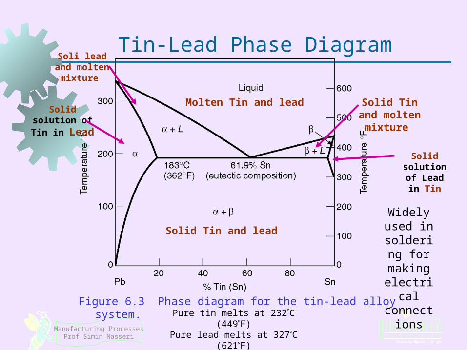
Tin-Lead Phase Diagram
Figure 6.3 Phase diagram for the tin‑lead alloy system.
Widely used in soldering for making electrical
connections
Molten Tin and lead
Solid Tin and lead
Solid Tin and molten mixture
Soli lead and molten mixture
Solid solution of Tin in Lead
Solid solution of Lead in Tin
Pure tin melts at 232C (449F)Pure lead melts at 327C (621F)
Ferrous Metals
Manufacturing ProcessesProf Simin Nasseri
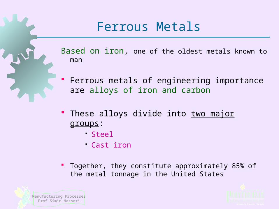
Ferrous Metals
Based on iron, one of the oldest metals known to man
Ferrous metals of engineering importance are alloys of iron and carbon
These alloys divide into two major groups: Steel Cast iron
Together, they constitute approximately 85% of the metal tonnage in the United States
Manufacturing ProcessesProf Simin Nasseri
Steel and Cast Iron
What is the difference between steel and cast iron?!
Manufacturing ProcessesProf Simin Nasseri
Steel and Cast Iron Defined
Steel = an iron‑carbon alloy containing from 0.02% to 2.1% carbon
Cast iron = an iron‑carbon alloy containing from 2.1% to about 4% or 5% carbon
Steels and cast irons can also contain other alloying elements besides carbon

Manufacturing ProcessesProf Simin Nasseri
Iron-Carbon Phase Diagram
Figure 6.4 Phase diagram for iron‑carbon system, up to about 6% carbon.
Watch the DVD of the book:Choose Additional Processes, then Heat treating.

Steel
Manufacturing ProcessesProf Simin Nasseri
Steel
An alloy of iron containing from 0.02% and 2.11% carbon by weight
Often includes other alloying elements: nickel, manganese, chromium, and molybdenum
Steel alloys can be grouped into four categories: 1. Plain carbon steels2. Low alloy steels3. Stainless steels4. Tool steels
Manufacturing ProcessesProf Simin Nasseri
Plain Carbon Steels
Carbon is the principal alloying element, with only small amounts of other elements (about 0.5% manganese is normal)
Strength of plain carbon steels increases with carbon content, but ductility is reduced
High carbon steels can be heat treated to form martensite, making the steel very hard and strong
Carbon Strength Carbon Ductility

Manufacturing ProcessesProf Simin Nasseri
Figure 6.12 Tensile strength and hardness as a function of carbon content in plain carbon steel (hot rolled).
Hardness is the characteristic of a solid material expressing its resistance to permanent deformation. It is expressed as Brinell hardness number or BHN or HB: P = applied force (kgf) D = diameter of indenter (mm) d = diameter of indentation (mm)

Manufacturing ProcessesProf Simin Nasseri
AISI-SAE Designation Scheme
Specified by a 4‑digit number system: 10XX, where 10 indicates plain carbon steel, and XX indicates carbon % in hundredths of percentage points
For example, 1020 steel contains 0.20% C Developed by American Iron and Steel Institute (AISI)
and Society of Automotive Engineers (SAE), so designation often expressed as AISI 1020 or SAE 1020

Manufacturing ProcessesProf Simin Nasseri
Plain Carbon Steels
1. Low carbon steels - contain less than 0.20% C Applications: automobile sheetmetal parts, plate
steel for fabrication, railroad rails
2. Medium carbon steels - range between 0.20% and 0.50% C Applications: machinery components and engine
parts such as crankshafts and connecting rods
3. High carbon steels - contain carbon in amounts greater than 0.50% Applications: springs, cutting tools and blades,
wear-resistant parts
Manufacturing ProcessesProf Simin Nasseri
Low Alloy Steels
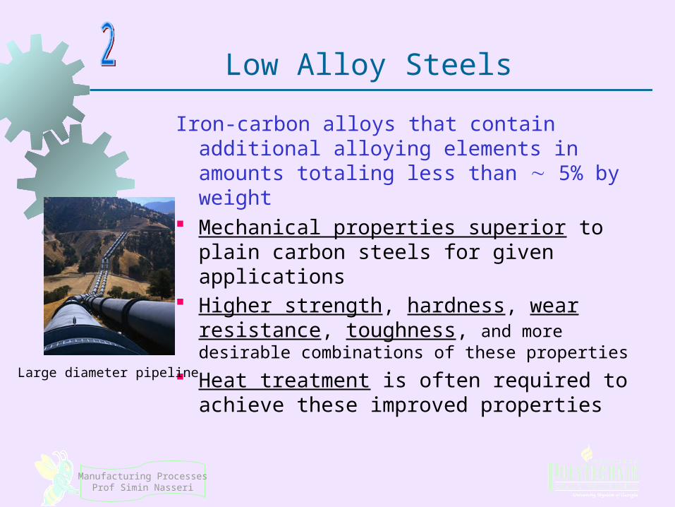
Iron‑carbon alloys that contain additional alloying elements in amounts totaling less than 5% by weight
Mechanical properties superior to plain carbon steels for given applications
Higher strength, hardness, wear resistance, toughness, and more desirable combinations of these properties
Heat treatment is often required to achieve these improved properties Large diameter pipeline
Manufacturing ProcessesProf Simin Nasseri
AISI-SAE Designation Scheme
AISI‑SAE designation uses a 4‑digit number system: YYXX, where YY indicates alloying elements, and XX indicates carbon % in hundredths of % points
Examples:
13XX - Manganese steel
20XX - Nickel steel
31XX - Nickel‑chrome steel
40XX - Molybdenum steel
41XX - Chrome‑molybdenum steel
Manufacturing ProcessesProf Simin Nasseri
Stainless Steel (SS)
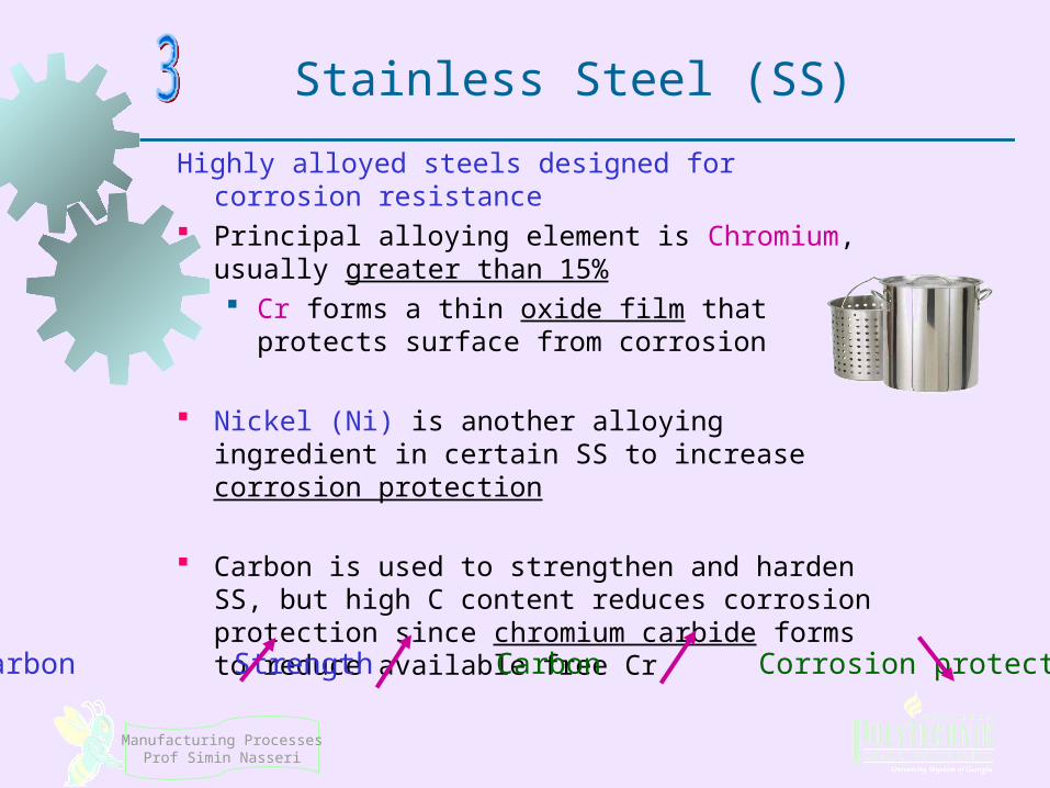
Highly alloyed steels designed for corrosion resistance
Principal alloying element is Chromium, usually greater than 15% Cr forms a thin oxide film that protects surface
from corrosion
Nickel (Ni) is another alloying ingredient in certain SS to increase corrosion protection
Carbon is used to strengthen and harden SS, but high C content reduces corrosion protection since chromium carbide forms to reduce available free Cr
Carbon Strength Carbon Corrosion protection

Manufacturing ProcessesProf Simin Nasseri
Properties of Stainless Steels
In addition to corrosion resistance, stainless steels are noted for their combination of strength and ductility While desirable in many applications, these
properties generally make stainless steel difficult to work in manufacturing
Significantly more expensive than plain C or low alloy steels
Manufacturing ProcessesProf Simin Nasseri
Types of Stainless Steel
Classified according to the predominant phase present at ambient temperature:
1. Austenitic stainless ‑ typical composition 18% Cr and 8% Ni
2. Ferritic stainless ‑ about 15% to 20% Cr, low C, and no Ni
3. Martensitic stainless ‑ as much as 18% Cr but no Ni, higher C content than ferritic stainless
Manufacturing ProcessesProf Simin Nasseri
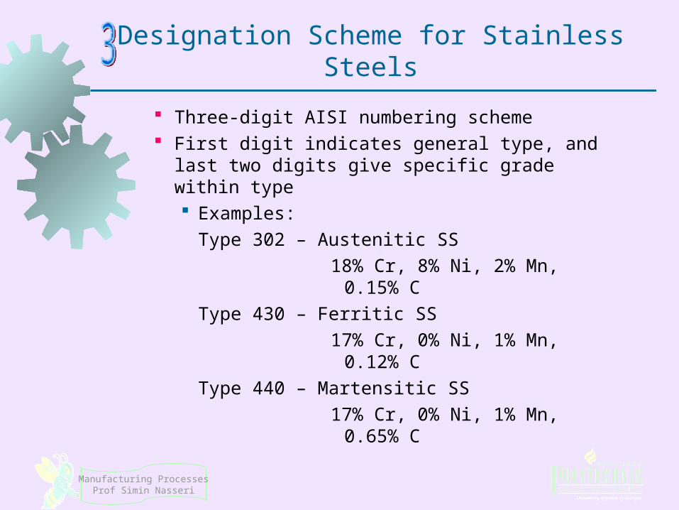
Designation Scheme for Stainless Steels
Three‑digit AISI numbering scheme First digit indicates general type, and last two
digits give specific grade within type Examples:
Type 302 – Austenitic SS
18% Cr, 8% Ni, 2% Mn, 0.15% C
Type 430 – Ferritic SS
17% Cr, 0% Ni, 1% Mn, 0.12% C
Type 440 – Martensitic SS
17% Cr, 0% Ni, 1% Mn, 0.65% C

Manufacturing ProcessesProf Simin Nasseri
Additional Stainless Steels Stainless steels developed in early 1900s Several additional high alloy steels have been
developed and are also classified as stainless steels:
4. Precipitation hardening stainless ‑ typical composition = 17% Cr and 7%Ni, with additional small amounts of alloying elements such as Al, Cu, Ti, and Mo (Aerospace applications)
5. Duplex stainless ‑ mixture of austenite and ferrite in roughly equal amounts (heat exchangers, pumps)
Manufacturing ProcessesProf Simin Nasseri
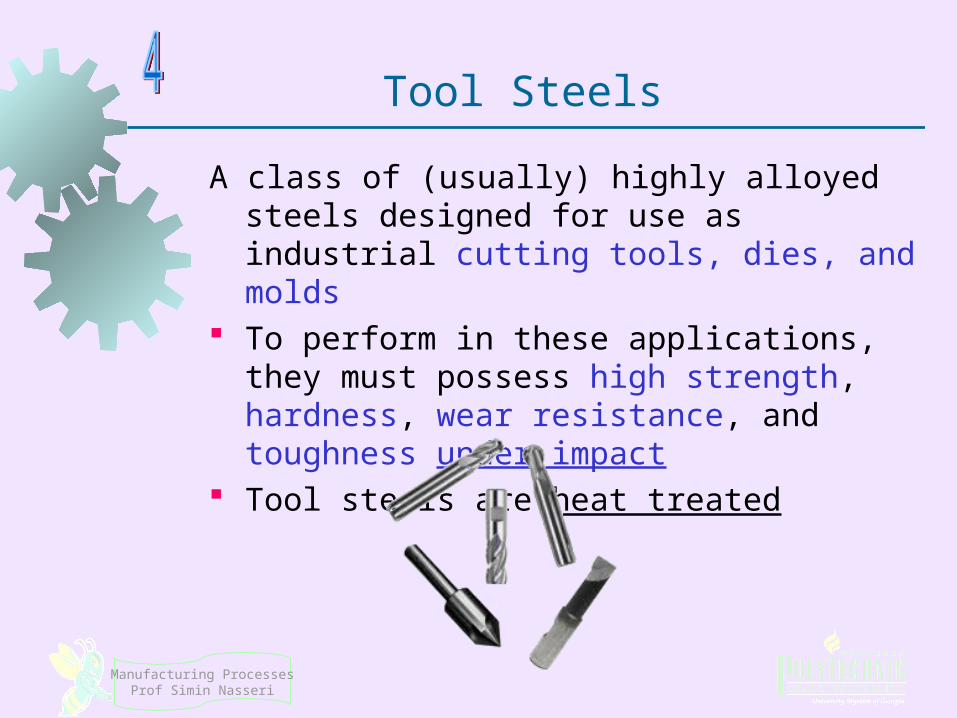
Tool Steels
A class of (usually) highly alloyed steels designed for use as industrial cutting tools, dies, and molds
To perform in these applications, they must possess high strength, hardness, wear resistance, and toughness under impact
Tool steels are heat treated
Manufacturing ProcessesProf Simin Nasseri
AISI Classification of Tools Steels
T, M High‑speed tool steels ‑ cutting tools in machining
H Hot‑working tool steels ‑ hot‑working dies for forging, extrusion, and die‑casting
D Cold‑work tool steels ‑ cold working dies for sheetmetal pressworking, cold extrusion, and forging
W Water‑hardening tool steels ‑ high carbon but little else
S Shock‑resistant tool steels ‑ tools needing high toughness, as in sheetmetal punching and bending
P Mold steels ‑ molds for molding plastics and rubber

Cast Iron
Manufacturing ProcessesProf Simin Nasseri
Cast Irons
Iron alloys containing from 2.1% to about 4% carbon and from 1% to 3% silicon
This composition makes them highly suitable as casting metals
Tonnage of cast iron castings is several times that of all other cast metal parts combined, excluding cast ingots in steel-making that are subsequently rolled into bars, plates, and similar stock
Overall tonnage of cast iron is second only to steel
among metals
Manufacturing ProcessesProf Simin Nasseri
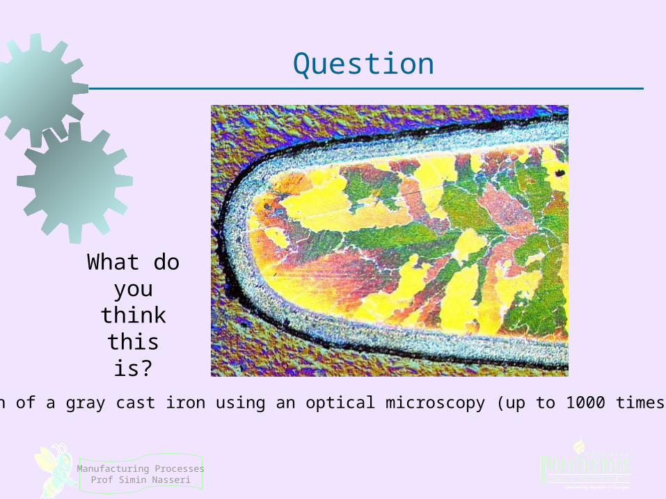
Question
What do you think this is?
Cross-section of a gray cast iron using an optical microscopy (up to 1000 times magnification)

Manufacturing ProcessesProf Simin Nasseri
Types of Cast Irons
Most important is gray cast iron
Other types include ductile iron, white cast iron, malleable iron, and various alloy cast irons
Ductile and malleable irons possess chemistries similar to the gray and white cast irons, respectively, but result from special processing treatments
Gray cast Iron Special melting and pouring treatment (Chemical treatment) Ductile IronWhite cast Iron Heat treatment Malleable Iron
Manufacturing ProcessesProf Simin Nasseri
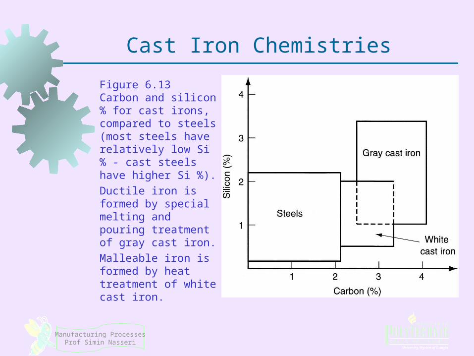
Cast Iron Chemistries
Figure 6.13 Carbon and silicon % for cast irons, compared to steels (most steels have relatively low Si % ‑ cast steels have higher Si %).
Ductile iron is formed by special melting and pouring treatment of gray cast iron.
Malleable iron is formed by heat treatment of white cast iron.