Embed Size (px)
Citation preview
1
“WET H2S CRACKING PROBLEM IN OIL REFINERY PROCESSES – MATERIAL SELECTION AND OPERATION CONTROL ISSUES
DP Ghosh
Haldia Refinery Indian Oil Corporation Limited
Purba Medinipur , Haldia - 721606 West Bengal, India
ABSTRACT
Operating an Oil refinery today means searching for methods to reduce risk to personnel and plant equipment. There are so many deterioration processes active on refinery equipment / piping etc. But this paper will concentrate on material selection and operational control issues related to “Wet H2S Cracking” in refinery process environment. This paper will also address operational control like wash water injection, corrosion inhibitor dosing and APS dosing for substantial reduction of “Wet H2S” related damages in operating equipment / piping. Inspection methods (WFMT etc) & its priorities, intervals and extent of inspection are also covered in the papers. Keywords: Wet H2S, SSC, HIC, Blistering and WFMPI
INTRODUCTION The “Wet H2S cracking” problem in oil industry was first recognized in the 1970’s and guidance on material requirements to avoid SSC was published at that time by NACE as MR0175. In earlier days, it was hoped that the blistering and hydrogen induced cracking (HIC) observed in many refinery process vessel were isolated occurrences. The findings of NACE international task group T-8-16 survey during 1990 i.e cracking of existing carbon steel pressure vessel in wet H2S process environment had also raised significant concern in the petroleum refining industry. And the survey in 1988-1990 had revealed cracking incident in “Wet H2S “ environment varied
1
2
from a low of 18 to 19 % in Crude units and Coker fractionation units to a high of 45 % in Fluid Catalytic Cracking (FCC) Light ends units. High cracking incident was also reported in other process units include FCC fractionation (41%), liquefied petroleum gas (LPG) (41%). Presently, a better appreciation of the consequences of wet H2S damages has been ascertained because handling of H2S rich process streams in oil industry has a safety consequence also and its mitigation methods are getting prime importance and selection of wet H2S cracking resistance material for various process units like FCCU, DHDS, COKER continues to be the thrust areas in future The safety issue is inescapable and can only be addressed by ensuring the proper facilities like proper material, suitable inspection frequency and timely replacement and this a also link up with economic consideration.
OVERVIEW OF WET H2S DAMAGES The “Wet H2S Cracking” problem in Oil refinery and Gas plant covers a range of damage mechanisms that can occur due to the effects of aqueous hydrogen charging in "Wet H2S" process environments (refinery or gas plant). Types of damage that can occur as a result of aqueous hydrogen charging include sulfide stress cracking (SSC) of hard weldments and microstructures, hydrogen blistering, hydrogen Induced cracking (HIC) and stress-oriented hydrogen induced cracking (SOHIC). Carbonate cracking is also a related mechanism, which is of concern in high pH streams containing significant levels of sulfide and carbonate ions. The key characteristic of Wet H2S cracking mechanisms involve charging of the steel with hydrogen at relatively low temperatures, most often as the result of corrosion process, which evolves hydrogen. The role of the H2S is to “poison” the hydrogen recombination reaction that would ordinarily occur and force the hydrogen atom to enter the metal structure rather than bubble off from the corroding surface. Wet H2S cracking occurs under acidic conditions like present in oil field applications. It also occurs in refinery applications where the pH is around 6 or higher due to presence of ammonia. Chloride may also present in some refinery streams, which generally increase corrosion. Cyanides may also present in some streams, which increase corrosion rates by reducing the protectiveness of iron sulfide corrosion products and also act as a strong hydrogen recombination “poison”.
REFINERY PROCESS UNITS AND ITS SECTIONS / EQUIPMENTS HAVING POTENTIAL
FOR “WET H2S DAMAGES” Blistering, HIC, SOHIC and SSC damage can occur throughout the refinery wherever there is a wet H2S environment. In Fluidized catalytic cracking unit (FCCU), Fractionator tower, fractionator’s overhead drums, absorber column, stripper column, WGC interstage coolers, separators and knockout drums and connected heat exchangers are prone to Wet H2S cracking problem. Debutaniser tower of FCCU is also vulnerable for SSC, blistering and HIC problem.
2
3
Presence of cyanides in FCCU overhead section will increase probability and severity of Wet H2S damages. Entire vapor recovery section of delayed coking unit is vulnerable for potential Wet H2S damage and presence of cyanides will significantly increase the probability and severity of blistering, HIC damage. Sour water stripper overhead systems are especially prone to Wet H2S corrosion problem and this will increase if cyanides are also present like sour water of FCCU. Amine regenerators over head systems are also prone to Wet H2S damage and cyanide has also similar effect. In hydro processing units increasing concentration of ammonium bisulfide increases the potential for blistering, HIC. Acid gas rich amine flash drum is also vulnerable for severe hydrogen blistering. Hydrogen absorption of carbon steels equipments due to result of wet ammonium bisulfide (NH4HS) corrosion in effluent condensers of hydro processing / hydro cracking units in refineries and in stripper column over head systems of hydro treating units are well known and thus blistering and HIC is also likely in the same sections. Carbonate cracking may be prevalent in the main fractionators overhead and wet gas compression system of Fluidized catalytic cracking units, sour water strippers and delayed coking unit. Failure of CS weld in HCO recycle circuit of RFCCU was observed at stresses considerably below the yield of hard metal due to sulfide stress cracking while processing wild naphtha of DHDS. The wild naphtha was having H2S content around 20,000-ppm wt and operating temperature was 40 degree C and operating pressure was at 5.0 Kg/ Cm2g pressure. The line originally was not PWHT and hardness was above 200 BHN.
DESCRIPTION OF SSC DAMAGE Sulfide stress cracking (SSC) is a form of cracking that involves hydrogen embrittlement of the metal by atomic hydrogen that is produced by the corrosion reaction of wet H2S with the metal. SSC is typically intergranular with little branching, and some times may contain some transgranular portions. SSC is more likely to occur in high strength (high- hardness) materials or in hard weld deposits or hard heat- affected zones (HAZs) of welds in lower- strength material. Environment severity leading to SSC Susceptibility to SSC is very much dependant on the degree of hydrogen charging in the material, which is primarily associated with the process environmental parameters like pH and sulfide content of the water. The lowest hydrogen flux in steels typically results from corrosion
3
4
in near natural pH solutions (pH 5.5-7.5). The hydrogen flux resulting from wet sulfide corrosion increases both as the pH increases and as the pH decreases from this near neutral range. Corrosion at the lower (more acidic) pH values is caused by higher concentrations of dissolved H2S in the water whereas corrosion at the higher (more alkaline) pH values is caused by higher concentrations of the bisulfide ion in the water. The sulfide content of the water is generally related to the H2S partial pressure in the gas phase associated with the water. In acidic sulfide environments, SSC is likely to occur when the H2S partial pressure exceeds 0.0003 MPa absolute or 3 mbara (0.05 psia). This corresponds to approximately 1-3 ppm of H2S dissolved in the water. The likelihood of SSC increases with increasing sulfide application in the water. At sulfide to concentrations greater than 1,000 ppm the likelihood of SSC is considered to be high. Presence of significant levels of cyanides (>20 ppm) in the water at pH values above 7.5 increases the hydrogen charging of the steel and can produce a high likelihood of SSC at lower sulfide concentrations. Susceptible material parameters for SSC Susceptibility to SSC is related to two materials parameters- hardness and tensile stress level. The hardness of the base metal is its strength level. Materials with a high hardness are more susceptible to SSC is generally considered a concern for materials with a tensile strength that exceeds 620 MPa (90 ksi). Therefore, SSC is highly likely to occur in the low- alloy steel and other more highly alloyed materials whose tensile strengths exceed this level. SSC of the typical carbon steel base metals used for pressure vessels and piping in wet H2S service in oilfield, gas and refining facilities is not a concern because of their low hardness levels. However, weld deposits and heat affected zones (HAZs) in welded carbon steel may contain local areas of high hardness due to the presence of non- tempered martensite and high residual stresses associated with the welding that could increase susceptibility to SSC. Guidance on environmental conditions leading to SSC of Carbon Steels Sulfide stress cracking (SSC) is especially dangerous because of the speed of cracking if susceptible steel is exposed to a H2S- containing environment whilst under some level of tensile stress; potentially causing a crack within hours. This was recognized in the 1970's and the National Association of Corrosion Engineers (NACE) in the USA (Materials Recommendation, MR0175) published the first document giving guidance on materials requirements to avoid SSC at that time. That document defined a specific environmental condition, which was termed "sour service” within which there is a risk of SSC of materials that are susceptible. Sour conditions were defined from the total pressure of the system and the concentration of H2S in the gas phase. In the mid 1990's the European Federation of Corrosion (EFC) published two European documents. EFC publication 16 was concerned with carbon and low alloy steels and EFC publication 17 was concerned with corrosion resistant alloys. EFC 16 defined sour service in terms of the partial pressure of H2S and the pH of the environment.
4
5
Most recently (2003), the above-mentioned two approaches were combined in a new ISO standard, drawing together the American and European work in an ISO standard, ISO 15156. This allows the user to select the definition of sour service based on the NACE approach (considering only the partial pressure of H2S), or the EFC approach (considering the partial pressure of H2S and the pH of the environment). Guidance on environmental conditions leading to SCC of Stainless Steels
Early versions of MR 0175 probably did not give any guidance on the conditions within which stainless steels could be safely used in sour service as they originally concentrated on carbon steels. However, later versions incorporated advice on a range of materials including 300- series stainless steels. The following text quotes section 3.5.1 from the 1995 version of MR 0175:
“Austenitic stainless steels with chemical compositions as specified in accordance with the standards listed in Table 1, either cast or wrought, are acceptable at a hardness of 22 HRC maximum in the annealed condition, provided they are free of cold work designed to enhance their mechanical properties".
However, it is now recognized that stainless steels have a risk of chloride stress cracking in sour environments, which contain chloride ions. The exact combinations of conditions, which are most likely to result in cracking, are not fully defined for every combination of chloride ion concentration, partial pressure, pH and temperature. However, the new ISO 15156 document has fixed some guidelines for solution annealed (i.e. without cold work) 300 series stainless steels at a maximum hardness of 22HRC. This states two separate limiting conditions, one for low chloride ion concentration and one for unlimited chloride ion concentration as quoted below.
Temperature 0C
Partial pressure of H2S (psi)
Chloride concentration (ppm)
Comments
60 15 Any Any combination of chloride ion and in- situ pH are allowed
60 50 50 Any pH found in normal producing environments is acceptable
Specifically for instrument tubing and associated compression fittings the document states in Table A.4 that S31600 (AISI 316) stainless steel has been used to date without environmental restriction and so no limits are set on its use in sour service. A comment is added that "some combinations" of temperature, in- situ pH, partial pressure of H2S and chloride ion concentration may not be acceptable.
5
6
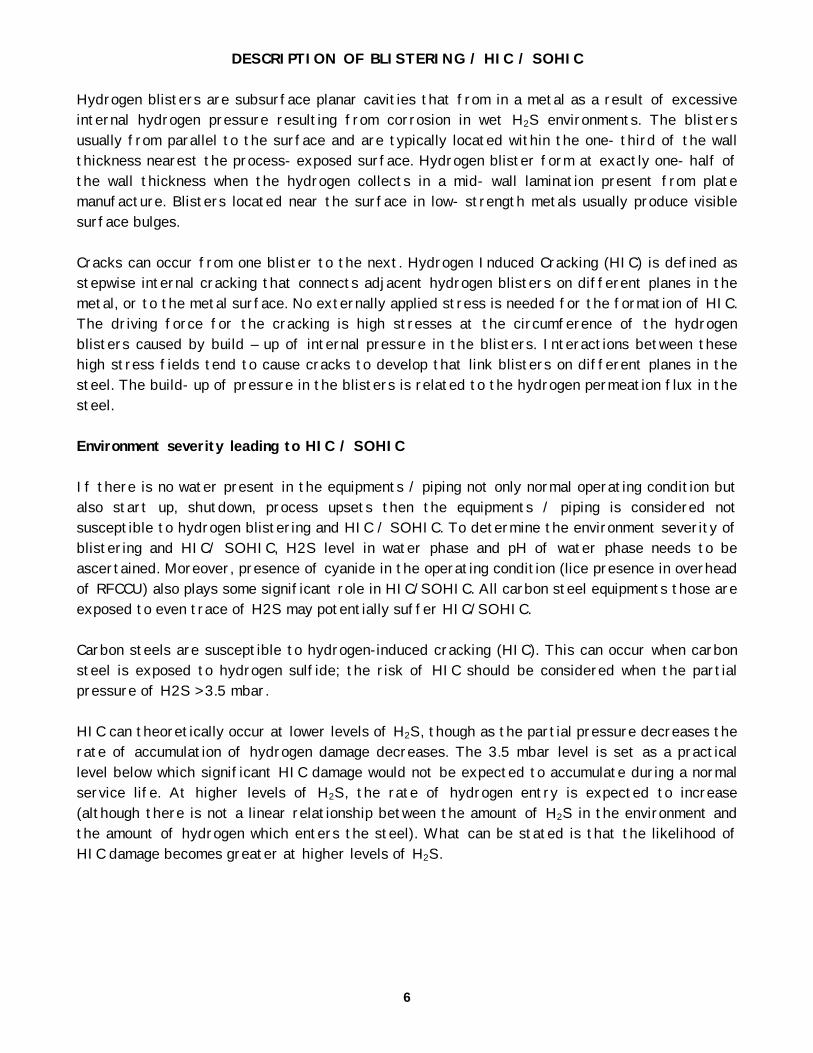
DESCRIPTION OF BLISTERING / HIC / SOHIC Hydrogen blisters are subsurface planar cavities that from in a metal as a result of excessive internal hydrogen pressure resulting from corrosion in wet H2S environments. The blisters usually from parallel to the surface and are typically located within the one- third of the wall thickness nearest the process- exposed surface. Hydrogen blister form at exactly one- half of the wall thickness when the hydrogen collects in a mid- wall lamination present from plate manufacture. Blisters located near the surface in low- strength metals usually produce visible surface bulges. Cracks can occur from one blister to the next. Hydrogen Induced Cracking (HIC) is defined as stepwise internal cracking that connects adjacent hydrogen blisters on different planes in the metal, or to the metal surface. No externally applied stress is needed for the formation of HIC. The driving force for the cracking is high stresses at the circumference of the hydrogen blisters caused by build – up of internal pressure in the blisters. Interactions between these high stress fields tend to cause cracks to develop that link blisters on different planes in the steel. The build- up of pressure in the blisters is related to the hydrogen permeation flux in the steel. Environment severity leading to HIC / SOHIC If there is no water present in the equipments / piping not only normal operating condition but also start up, shutdown, process upsets then the equipments / piping is considered not susceptible to hydrogen blistering and HIC / SOHIC. To determine the environment severity of blistering and HIC/ SOHIC, H2S level in water phase and pH of water phase needs to be ascertained. Moreover, presence of cyanide in the operating condition (lice presence in overhead of RFCCU) also plays some significant role in HIC/SOHIC. All carbon steel equipments those are exposed to even trace of H2S may potentially suffer HIC/SOHIC. Carbon steels are susceptible to hydrogen-induced cracking (HIC). This can occur when carbon steel is exposed to hydrogen sulfide; the risk of HIC should be considered when the partial pressure of H2S > 3.5 mbar. HIC can theoretically occur at lower levels of H2S, though as the partial pressure decreases the rate of accumulation of hydrogen damage decreases. The 3.5 mbar level is set as a practical level below which significant HIC damage would not be expected to accumulate during a normal service life. At higher levels of H2S, the rate of hydrogen entry is expected to increase (although there is not a linear relationship between the amount of H2S in the environment and the amount of hydrogen which enters the steel). What can be stated is that the likelihood of HIC damage becomes greater at higher levels of H2S.
6
7
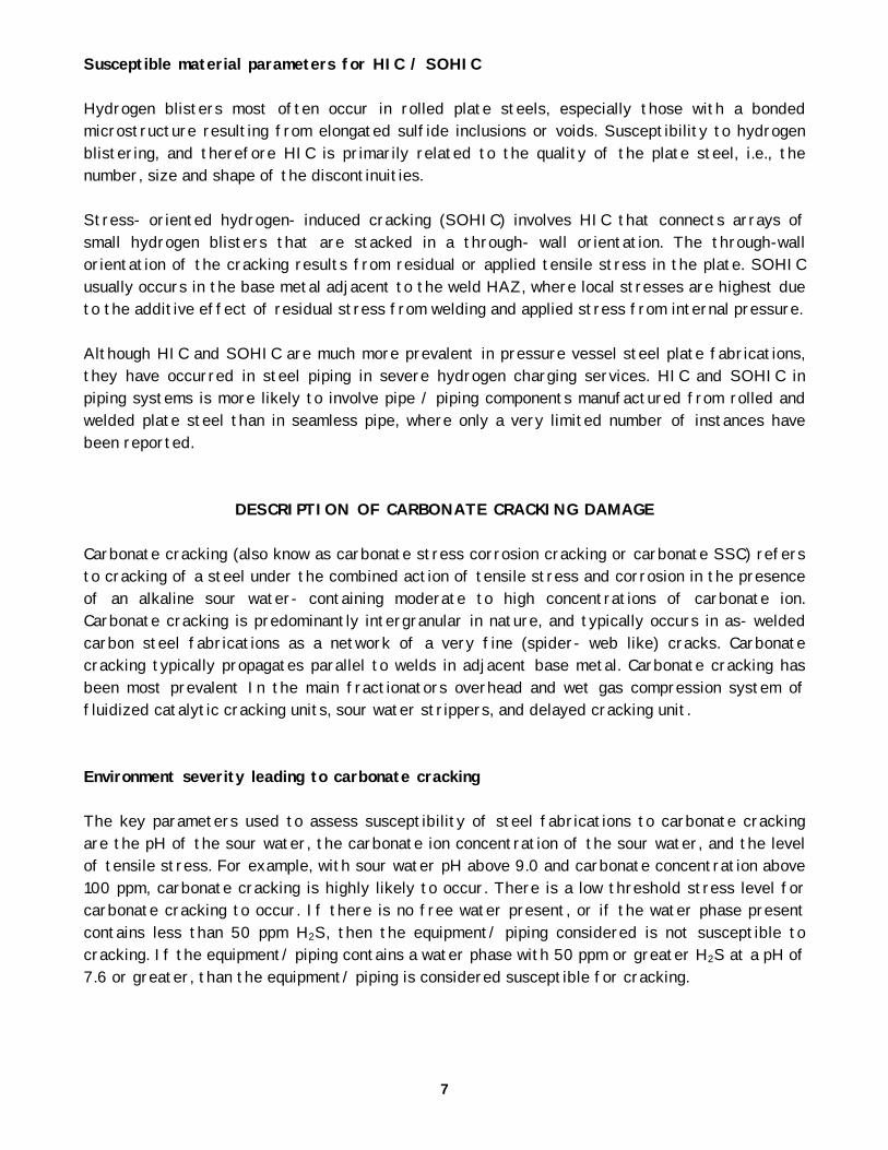
Susceptible material parameters for HIC / SOHIC Hydrogen blisters most often occur in rolled plate steels, especially those with a bonded microstructure resulting from elongated sulfide inclusions or voids. Susceptibility to hydrogen blistering, and therefore HIC is primarily related to the quality of the plate steel, i.e., the number, size and shape of the discontinuities. Stress- oriented hydrogen- induced cracking (SOHIC) involves HIC that connects arrays of small hydrogen blisters that are stacked in a through- wall orientation. The through-wall orientation of the cracking results from residual or applied tensile stress in the plate. SOHIC usually occurs in the base metal adjacent to the weld HAZ, where local stresses are highest due to the additive effect of residual stress from welding and applied stress from internal pressure. Although HIC and SOHIC are much more prevalent in pressure vessel steel plate fabrications, they have occurred in steel piping in severe hydrogen charging services. HIC and SOHIC in piping systems is more likely to involve pipe / piping components manufactured from rolled and welded plate steel than in seamless pipe, where only a very limited number of instances have been reported.
DESCRIPTION OF CARBONATE CRACKING DAMAGE Carbonate cracking (also know as carbonate stress corrosion cracking or carbonate SSC) refers to cracking of a steel under the combined action of tensile stress and corrosion in the presence of an alkaline sour water- containing moderate to high concentrations of carbonate ion. Carbonate cracking is predominantly intergranular in nature, and typically occurs in as- welded carbon steel fabrications as a network of a very fine (spider- web like) cracks. Carbonate cracking typically propagates parallel to welds in adjacent base metal. Carbonate cracking has been most prevalent In the main fractionators overhead and wet gas compression system of fluidized catalytic cracking units, sour water strippers, and delayed cracking unit. Environment severity leading to carbonate cracking The key parameters used to assess susceptibility of steel fabrications to carbonate cracking are the pH of the sour water, the carbonate ion concentration of the sour water, and the level of tensile stress. For example, with sour water pH above 9.0 and carbonate concentration above 100 ppm, carbonate cracking is highly likely to occur. There is a low threshold stress level for carbonate cracking to occur. If there is no free water present, or if the water phase present contains less than 50 ppm H2S, then the equipment/ piping considered is not susceptible to cracking. If the equipment/ piping contains a water phase with 50 ppm or greater H2S at a pH of 7.6 or greater, than the equipment/ piping is considered susceptible for cracking.
7
8
Susceptible material parameters for carbonate cracking As- welded or as- bent carbon steel fabrications are susceptible to carbonate cracking because of the level of residual stress remaining after fabrication. If the equipment/ piping is properly stress relieved, then it is considered not susceptible to carbonate cracking.
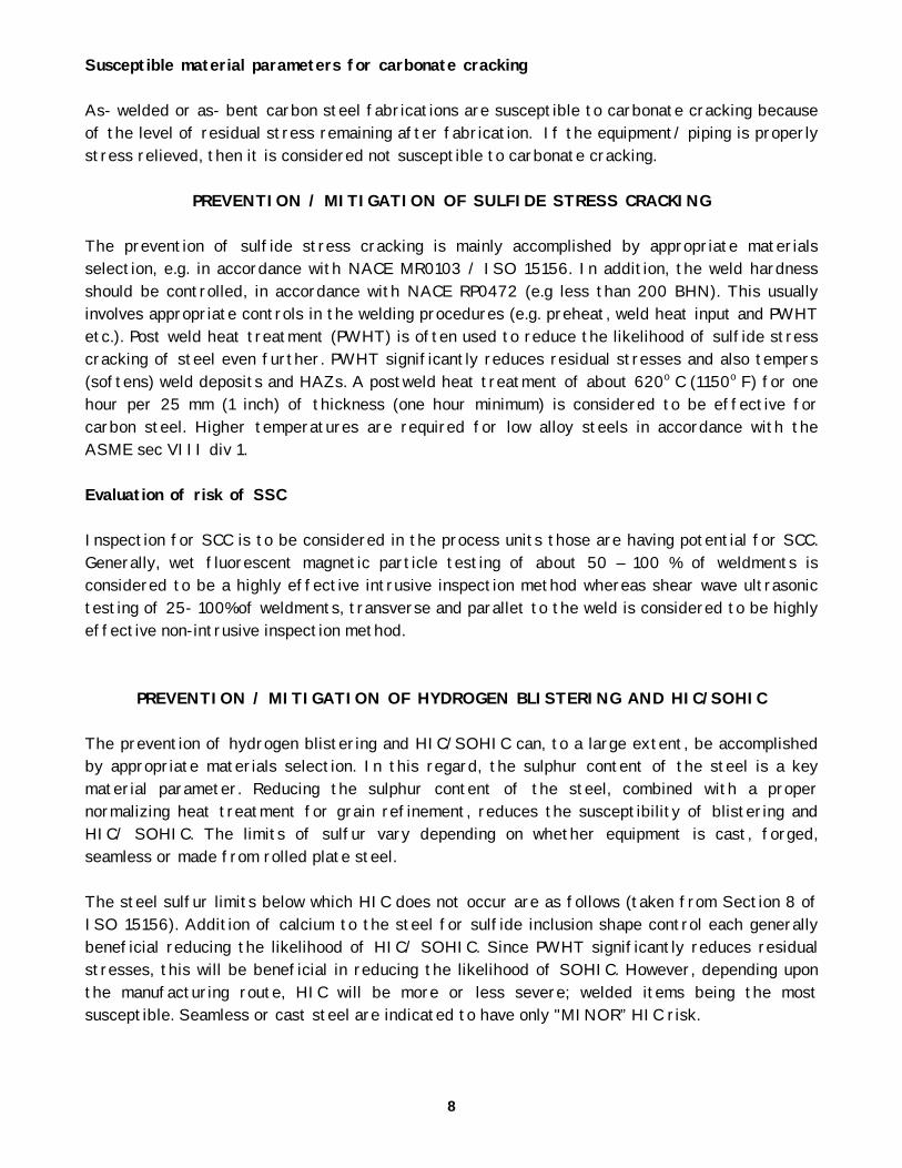
PREVENTION / MITIGATION OF SULFIDE STRESS CRACKING The prevention of sulfide stress cracking is mainly accomplished by appropriate materials selection, e.g. in accordance with NACE MR0103 / ISO 15156. In addition, the weld hardness should be controlled, in accordance with NACE RP0472 (e.g less than 200 BHN). This usually involves appropriate controls in the welding procedures (e.g. preheat, weld heat input and PWHT etc.). Post weld heat treatment (PWHT) is often used to reduce the likelihood of sulfide stress cracking of steel even further. PWHT significantly reduces residual stresses and also tempers (softens) weld deposits and HAZs. A postweld heat treatment of about 620o C (1150o F) for one hour per 25 mm (1 inch) of thickness (one hour minimum) is considered to be effective for carbon steel. Higher temperatures are required for low alloy steels in accordance with the ASME sec VIII div 1. Evaluation of risk of SSC Inspection for SCC is to be considered in the process units those are having potential for SCC. Generally, wet fluorescent magnetic particle testing of about 50 – 100 % of weldments is considered to be a highly effective intrusive inspection method whereas shear wave ultrasonic testing of 25- 100%of weldments, transverse and parallet to the weld is considered to be highly effective non-intrusive inspection method.
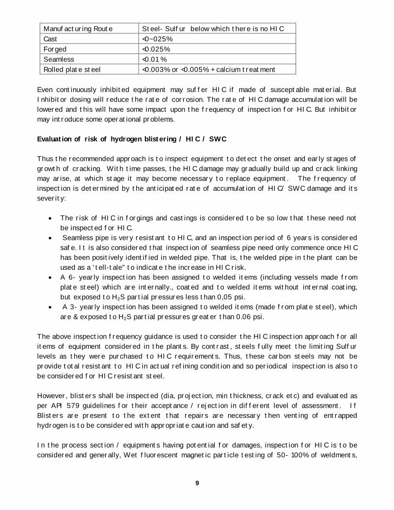
PREVENTION / MITIGATION OF HYDROGEN BLISTERING AND HIC/SOHIC The prevention of hydrogen blistering and HIC/SOHIC can, to a large extent, be accomplished by appropriate materials selection. In this regard, the sulphur content of the steel is a key material parameter. Reducing the sulphur content of the steel, combined with a proper normalizing heat treatment for grain refinement, reduces the susceptibility of blistering and HIC/ SOHIC. The limits of sulfur vary depending on whether equipment is cast, forged, seamless or made from rolled plate steel. The steel sulfur limits below which HIC does not occur are as follows (taken from Section 8 of ISO 15156). Addition of calcium to the steel for sulfide inclusion shape control each generally beneficial reducing the likelihood of HIC/ SOHIC. Since PWHT significantly reduces residual stresses, this will be beneficial in reducing the likelihood of SOHIC. However, depending upon the manufacturing route, HIC will be more or less severe; welded items being the most susceptible. Seamless or cast steel are indicated to have only "MINOR” HIC risk.
8
9
Manufacturing Route Steel- Sulfur below which there is no HIC Cast <0~025% Forged <0.025% Seamless <0.01 % Rolled plate steel <0.003% or <0.005% + calcium treatment
Even continuously inhibited equipment may suffer HIC if made of susceptable material. But Inhibitor dosing will reduce the rate of corrosion. The rate of HIC damage accumulation will be lowered and this will have some impact upon the frequency of inspection for HIC. But inhibitor may introduce some operational problems. Evaluation of risk of hydrogen blistering / HIC / SWC Thus the recommended approach is to inspect equipment to detect the onset and early stages of growth of cracking. With time passes, the HIC damage may gradually build up and crack linking may arise, at which stage it may become necessary to replace equipment. The frequency of inspection is determined by the anticipated rate of accumulation of HIC/ SWC damage and its severity:
• The risk of HIC in forgings and castings is considered to be so low that these need not be inspected for HIC.
• Seamless pipe is very resistant to HIC, and an inspection period of 6 years is considered safe. It is also considered that inspection of seamless pipe need only commence once HIC has been positively identified in welded pipe. That is, the welded pipe in the plant can be used as a 'tell-tale" to indicate the increase in HIC risk.
• A 6- yearly inspection has been assigned to welded items (including vessels made from plate steel) which are internally., coated and to welded items without internal coating, but exposed to H2S partial pressures less than 0,05 psi.
• A 3- yearly inspection has been assigned to welded items (made from plate steel), which are & exposed to H2S partial pressures greater than 0.06 psi.
The above inspection frequency guidance is used to consider the HIC inspection approach for all items of equipment considered in the plants. By contrast, steels fully meet the limiting Sulfur levels as they were purchased to HIC requirements. Thus, these carbon steels may not be provide total resistant to HIC in actual refining condition and so periodical inspection is also to be considered for HIC resistant steel. However, blisters shall be inspected (dia, projection, min thickness, crack etc) and evaluated as per API 579 guidelines for their acceptance / rejection in different level of assessment. If Blisters are present to the extent that repairs are necessary then venting of entrapped hydrogen is to be considered with appropriate caution and safety. In the process section / equipments having potential for damages, inspection for HIC is to be considered and generally, Wet fluorescent magnetic particle testing of 50- 100% of weldments,
9
10
plus additional shear is considered to be a highly effective intrusive inspection method whereas no non-intrusive method is considered to be highly effective.
PREVENTION / MITIGATION OF CARBONATE CRACKING The prevention of carbonates cracking mainly accomplished by application of a post- fabrication stress- relieving heat treatment (e.g. post weld heat treatment) for susceptible equipment and piping. A heat treatment of about 620o C (1150o F) for one hour per 25 mm (1 inch) of thickness (one hour minimum) each considered and effective stress- reliving heat treatment to prevent carbonate cracking of carbon steel. Evaluation of risk of carbonate cracking Inspection for carbonate cracking is to be considered in the process units those are having potential for same and generally, wet fluorescent magnetic particle testing of 100% of repair welds and 50- 100% of other welds/ cold bends is considered to be a highly effective intrusive inspection method. Evaluation of risk of carbonate cracking shall be reassessed in totality for any major process chances like de-sulphurisation of FCCU feed. This de-sulphurodation will reduce the H2S level in the overhead system of FCCU and will increase the pH level (relatively) even may be upto 10 and thus requires Post weld heat treatment to avoid cracking in future.
OPERATION CONTROL ISSUES Hydrogen blistering problem in Delayed cracking unit, fluid catalytic cracking unit and their gas plants are due to presence of wet H2S, NH3 and cyanides. The most severe areas for blistering and weld cracking are in compressor after coolers, high-pressure knockout pot and the deethanizer. Some blistering and weld cracking may occur in the remainder of the equipment but there is much less occurrence and usually less severe blisters in size and depth. However, severity of problem in delayed cracking unit is less compared to catalytic cracking unit. In most of the refinery it is common practice to water wash the susceptible section of the unit in addition to water present from steam stripping, thus producing a wet environment, which contains hydrogen sulfide, ammonia and cyanide. This environment has produce hydrogen blistering and weld cracking. In these systems the ratio of hydrogen sulfide to ammonia controls the pH of the system. At pHs between 5.5 to 7.5, lowest corrosion and hydrogen blistering will occur. Corrosion at the lower pH values (more acidic) is caused by higher concentrations of dissolved H2S in water. Corrosion at the higher pH values (more alkaline) is caused by higher concentrations of the bisulfide ion in the water. There are varieties of approaches like water washing, polysulfide addition, as well as the use of organic filming inhibitors for prevention of both corrosion and hydrogen blistering in fluid cracking units. But there is some debate over effectiveness of corrosion inhibitors for preventing hydrogen blistering, as they do not prevent diffusion of hydrogen into the steel.
10
11
Controlling of cyanides is the most important aspect for controlling blistering and HIC related problem. By wash water injection, dilution of the amount of contaminants, among them cyanides also, present in the water separated in plant. The generally accepted industry norms for cyanides in the water solution is between 10- 20 ppm as because this limit allow the FeS layer to formed on the steel and for the existing layer to remain intact. But there is some limitation; dilution method for controlling cyanides problem is generally acceptable practice upto the level of 1500 ppm nitrogen level in the crude oil. Polysulfide injection along with wash water is producing protective layer and controlling corrosion. But polysulfide being a very unstable, its supply chain system is highly complicated. Some times it precipitates as free sulfur and causing dosage lines and pumps to clog up. On site polysulfide generation systems by peroxide injection is found to be the most suitable method for cyanide control. Injection of filming inhibitor has been researched in laboratory but its efficacy in process plant still in question technically as well as economically. Treatment of overhead condensates of FCCU with carbohydrazide is also a suggested method for prevention of blistering problem in FCCU. The amount of carbohydrazide used to treat these overheads may vary from as little as 0.5 ppm, up to as much as 100-200 ppm.
CONCLUSIONS
For wet H2S system, low sulphur steel is to be used with qualified HIC resistant properties (CSR, CLR, CTR). During fabrication, recommended weld hardness with PWHT shall be maintained for SSC resistant steel. Wet H2S system is to be periodically re-inspected even if made of HIC resistant steel because these steel may not be total resistant in actual refinery operation. For any major operational changes, total system shall be critically reviewed with respected to Carbonate cracking also. References and Bibliography
1. ISO 15156/ NACE MR0175 Petroleum and Natural Gas Industries - Materials for Use in H2S- Containing Environments in Oil and Gas Production. Published by ISO, Dec 2003
2. EFC16 "Guidelines On Materials Requirements For Carbon And Low Alloy Steels For H2S Containing Environments In Oil And Gas Production", published by The Institute of Materials, London 1995
3. EFC17 "Corrosion Resistant Alloys For Oil And Gas Production: Guidelines On General Requirements and Test Methods For H2S Service.", published by The Institute of Materials, London 1996
4. NACE MR 0103: Materials Resistant to Sulfide Stress Cracking in Corrosive Petroleum Refining Environments (2003).
11
12
5. “Sulfide Stress Cracking” in API Publication 581, Risk- Based Inspection Base Resource Document, 1st Edition, May 2000.
6. “Hydrogen- Induced Cracking and Stress- Oriented Hydrogen Induced Cracking in Hydrogen Sulfide Services (HIC/ SOHIC- H2S)” in API Publication 581, Risk- Based Inspection Base Resource Document, 1st Edition, May 2000.
7. “Carbonate Cracking” in API Publication 581, Risk- Based Inspection Base Resource Document, 1st Edition, May 2000.
8. NACE RP 0472: Methods and Controls to Prevent In- Service Environmental Cracking of Carbon Steel Weldments in Corrosive Petroleum Refining Environments (2000).
9. NACE RP 0296: Guidelines for Detection, Repair, and Mitigation of Cracking of Existing Petroleum Refinery Pressure Vessels in Wet H2S Environments (2004).
10. J. H. Kmetz and D.J. Truax, Carbonate Stress Corrosion Cracking of Carbon Steel in Refinery FCC Main Fractionator Overhead Systems, NACE paper # 2006.
11. R.R. Petrie and E.M. Moore, Jr. Determining the Suitability of Existing Pipelines and Producing Facilities for Wet South Service, Materials Performance 28, 6 (June 1989), pp. 59-65.
12. Singh, V, "Performance of Austenitic Stainless Steels in Wet Sour Gas - Parts 1 and 2 Materials Performance, August and September 2004
12