Embed Size (px)
Citation preview
ARMY RESEARCH LABORATORY
Metallographic Observations of Rolled-Homogeneous-Armor Specimens
From Plates Perforated by Shaped Charge Jets
Claire D. Krause Martin N. Raftenberg
APPROVED FOR PUBUC RELEASE; DISTRIBUTION IS UNUMITED.
June 1993
NOTICES
Destroy this report when it is no longer needed. DO NOT return it to the originator.
Secondary distribution of this report is prohibited.
Additional copies of this report may be obtained from the Defense Technical Information Center, Cameron Station, Alexandria, VA 22304-6145.
The findings of this report are not to be construed as an official Department of the Army position, unless so designated by other authorized documents.
The use of trade names or manufacturers' names in this report does not constitute indorsement of any commercial products.
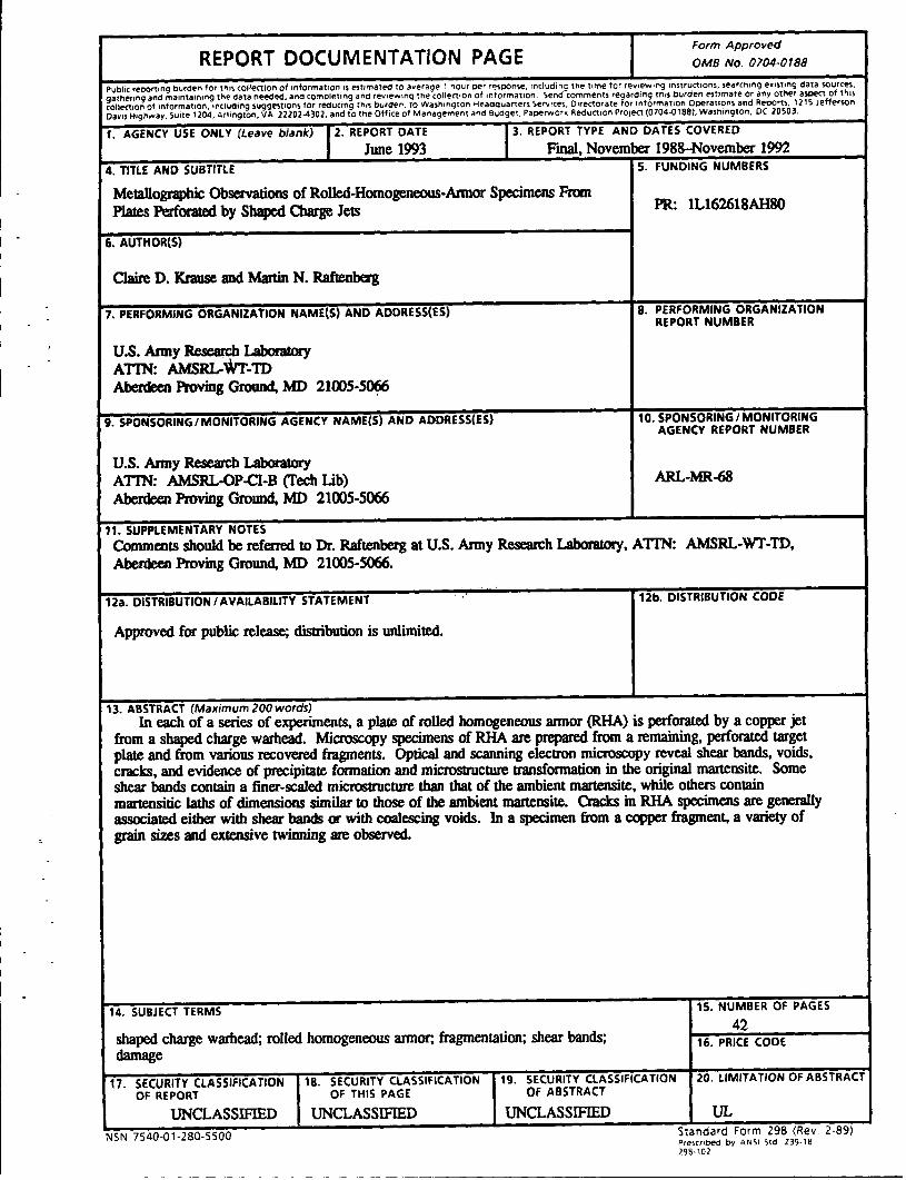
REPORT DOCUMENTATION PAGE Form Approved
OMB No. 0704-0788
Public repOrting burden for thiS collection of IMfOrmatron 15 est1mated to a11erage 1 nour per respon!te. rnclud1ng the trme for rev•ew•ng instructtons. iearcr•nng exrst1ng data sourctos.
gathermg an~ ma1nta1ntng the d.ata n~ed. and completi.ng and rev•ew1ng the collect• on of •nformatiOn. Send comments re~arding thrs burden est1mate or any other aK)ect of thas
collectron of 1nformat10n. •nctudtng suggestiOns tor reductng thfS buroen. to Wash.ngton Headquarters Servrc~. 01rectorate or 1nformat1on Operations and Reports. \215 Jefferson
Davrs Hrghway, Suite 1204, Arlington, VA 22202-4302. and to the Office of Management and Budget. Paperwork RE!duct10n PrOJect (0704-0188). Washington, DC 20503.
1. AGENCY USE ONLY (Leave blank) ,2. REPORT DATE
June 1993 ,3. REPORT TYPE AND DATES COVERED
Fmal, November 1988-November 1992 4. TITLE AND SUBTITLE 5. FUNDING NUMBERS
Metallographic Observations of Rolled-Homogeneous-Armor Specimens From PR: 1L162618AH80 Plates Perforau:d by Shaped OJarge Jets
6. AUTHOR(S)
Claire D. Krause and Martin N. Raftenbezg
7. PERFORMING ORGANIZATION NAME(S) AND ADDRESS(ES) 8. PERFORMING ORGANIZATION REPORT NUMBER
u.s. Army Research Laboraloly ATIN: AMSRL-WT-1D Aberdeen Proving Ground, MD 21005-~
9. SPONSORING/MONITORING AGENCY NAME(S) AND AODRESS(ES) 10. SPONSORING I MONITORING AGENCY REPORT NUMBER
u.s. Army Research Laboratory ATIN: AMSRL-OP-CI-B (Tech lib) ARL-MR-68
Aberdeen Proving Ground, MD 21005-5066
11. SUPPLEMENTARY NOTES
Comments should be referred to Dr. Raftenbezg at U.S. Army Research Laboratory, ATIN: AMSRL-WI'-TD, Aberdeen Proving Ground, MD 21005-5066.
12a. DISTRIBUTION I AVAILABILITY STATEMENT .. 12b. DISTRIBUTION CODE
Approved for public release; distribution is unlimited.
13. ABSTRACT (Maximum 200 words)
In each of a series of experiments, a plate of rolled homogeneous annor (RHA) is perforated by a copper jet from a shaped charge warhead. Microscopy specimens of RHA are prepared from a remaining, perforated target plate and from various recovered fragments. Optical and scanning electron microscopy reveal shear bands, voids, cracks, and evidence of precipitate fonnation and microstructure transfonnation in the original martensite. Some shear bands contain a finer-scaled microsb1Jcture than that of the ambient martensite, while others contain martensitic laths of dimensions similar to those of the ambient martensite. Cracks in RHA specimens are generally associated either with shear bands ar with coalescing voids. In a specimen from a copper fragment, a variety of grain sizes and extensive twinning are observed.
14. SUBJECT TERMS
shaped charge warhead; rolled homogeneous annor; fragmemation; shear bands; damage
17. SECURITY CLASSIFICATION 18. SECURITY CLASSIFICATION 19. SECURITY CLASSIFICATION OF REPORT OF THIS PAGE OF ABSTRACT
UNCLASSIFIED UNCLASSIFIED UNCLASSIFIED
NSN 7540·01·280-5500
15. NUMBER OF PAGES
42 16. PRICE CODE
20. LIMITATION OF ABSTRACT
UL Standard Form 298 (Rev. 2-89) Pre>CnbE!d by ANSI Std Z39-1B 196-102
.INTENTIONALLY LEFT BLANK.
ii
ACKNOWLEDGMENTS
The authors would like to recognize the efforts of several staff members of the U.S. Army
Research Laboratory. Dr. Pat Kingman assisted with the use of the scanning electron
microscope. Mr. David E. Mackenzie helped with the preparation of specimens for
microscopy. The range firing at Range 7 A was performed by Messrs. Grat E. Blackburn,
David R. Schall, and Sterling C. Shelley, Jr. The three firings at Range 16 were performed
by Messrs. Carl V. Paxton and Joseph W. Gardiner. Dr. LeeS. Magness provided a very
helpful review of the manuscript.
iii
INTENTIONALLY LEFT BLANK.
IV
TABLE OF CONTENTS
ACKNOWLEDGMENTS . . . . . . . . . . . . . . . . . . . . . . . . . . . . . . . . . . . . . iii
LIST OF FIGURES . . . . . . . . . . . . . . . . . . . . . . . . . . . . . . . . . . . . . . . . . vii
LIST OF TABLES . . . . . . . . . . . . . . . . . . . . . . . . . . . . . . . . . . . . . . . . . ix
1. INTRODUCllON . . . . . . . . . . . . . . . . . . . . . . . . . . . . . . . . . . . . . . . . . . 1
2. METHODS . . . . . . . . . . . . . . . . . . . . . . . . . . . . . . . . . . . . . . . . . . . . . . . 1
3. OBSERVATIONS . . . . . . . . . . . . . . . . . . . . . . . . . . . . . . . . . . . . . . . . . . 3
3.1 Perforated RHA Plate from Rd. 10771 . . . . . . . . . . . . . . . . . . . . . . . . . 3 3.2 RHA Fragments from Rds. 4098, 4099 and 4100 . . . . . . . . . . . . . . . . . . 4
4. DISCUSSION . . . . . . . . . . . . . . . . . . . . . . . . . . . . . . . . . . . . . . . . . . . . . 5
DISTRffiUTION LIST . . . . . . . . . . . . . . . . . . . . . . . . . . . . . . . . . . . . . . . 31
v

INTENTIONALLY LEFr BLANK.
vi
Figure
1.
2.
3.
4.
5.
6.
7.
8.
9.
10.
11.
LIST OF FIGURES
Setup for range firings
Pre-impact and post-perforation radiographs for a standoff of 3.00 C.D.
and a target plate thickness of 13 mm . . . . . . . . . . . . . . . . . . . . . . . . . .
Pre-impact radiograph from Rd. 4100 ........................... .
Sectioning of perforated RHA target plate from Rd. 10771 . . . . . . . . . . . . . .
Slice of target plate from Rd. 10771 with two cracks emanating from
perforation hole indicated . . . . . . . . . . . . . . . . . . . . . . . . . . . . . . . . . . .
Tempered martensite observed in perforated target plate ............... .
Crack #1 in Figure 5 and adjoining shear band ..................... .
Enlargement of Figure 7 showing crack to be surrounded by a shear
band .................................... · ............. .
Enlargement of Figure 7 showing relationship of crack tip to shear
band ................................................. .
Further enlargement of Figure 7 showing details of the shear band . . . . . . . .
Crack #2 in Figure 5 and adjoining shear band . . . . . . . . . . . . . . . . . . . . . .
12. A shear band with a microstructure similar to that of surrounding
10
11
12
13
14
14
15
15
16
16
17
martensite . . . . . . . . . . . . . . . . . . . . . . . . . . . . . . . . . . . . . . . . . . . . . . 18
13. A shear band associated with a crack at one end and blending with the
ambient martensite at the other . . . . . . . . . . . . . . . . . . . . . . . . . . . . . . . 19
14. Voids have coalesced to form a crack in RHA . . . . . . . . . . . . . . . . . . . . . . 20
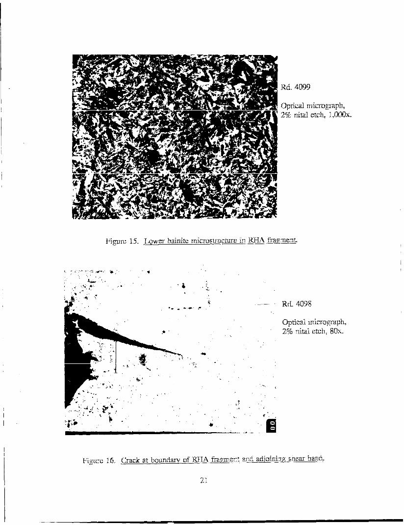
15. Lower bainite microstructure in RHA fragment . . . . . . . . . . . . . . . . . . . . . . 21
16. Crack at boundary of RHA fragment and adjoining shear band . . . . . . . . . . . 21
17. Shear band that meanders into interior of RHA fragment . . . . . . . . . . . . . . . 22
vii
--------------------------------------~~~-~-~~
~~-~--
Figure
18. Shear band that bifurcates and abruptly changes direction in an RHA fragment .............................................. . 23
19. Enlargement of Figure 18 in region of shear band bifurcation . . . . . . . . . . . . 23
20. RHA fragment bounded by a band of dendritic structure 24
21. Enlargement of Figure 20 with dendritic structure shown 25
22. Further enlargement of dendritic structure in Figure 20 . . . . . . . . . . . . . . . . 26
23. Band of striations near RHA fragment's boundary . . . . . . . . . . . . . . . . . . . . 26
24. Copper fragment with variety of grain sizes and evidence of twinning . . . . . . 27
Vlll
1.
2.
LIST OF TABLES
Round Descriptions . . . . . . . . . . . . . . . . . . . . . . . . . . . . . . . . . . . . . . . . .
Vickers and Rockwell C Hardness Measurements Across the RHA Fragment of Figures 21 and 22 (1 00 g Load Used) . . . . . . . . . . . . . . . . . . . . . . . .
IX
9
9

INTENTIONALLY LEFJ' BLANK.
X
1. INTRODUCTION
Four experiments are performed, in each of which a shaped charge warhead is fired
at normal incidence into a plate of rolled homogeneous armor (RHA). The same type of
warhead is used in all experiments. The two parameters varied in the series are the
standoff, or distance between charge base and the target plate, and the target plate
thickness. Metallographic observations of RHA specimens from a perforated target plate
from one experiment and from recovered fragments from the other three experiments will
be presented. Both optical and scanning electron micrographs will reveal the presence of
five features that presumably resulted from the penetration event: (i) shear bands, (ii)
voids, (iii) cracks, (iv) precipitates, and (v) evidence of changes in the martensitic
microstructure.
Two companion reports (Raftenberg 1992, to be published) present other data from
these same four experiments. These data include: (i) flash radiographs, both of the jet
prior to impact and of the behind-armor-debris pattern at specific times following
perforation; (ii) measurements pertaining to the final geometry of the target plate hole;
(iii) measurements of the total mass lost by the target plate; (iv) observations of the
fracture surface pattern near the target plate hole; and (v) geometrical observations on
the largest recovered fragments. Together, the three reports are intended to provide an
overview of the physics of RHA plate perforation by a shaped charge jet.
Section 2 of this report will describe the four experiments from which RHA
specimens were obtained. Also described here are the specimen preparation procedure
and the optical microscope and scanning electron microscope (SEM) employed. Section 3
presents metallographic observations of the RHA specimens. Specifically, Subsection 3.1
is devoted to specimens prepared from a perforated target plate, and Subsection 3.2 to
specimens prepared from recovered fragments. Section 4 follows with a discussion of the
results.
2. METHODS
The shaped charge warhead used throughout the four experiments is described in
Raftenberg (to be published). This warhead contains a conical liner composed of OFHC
copper and has a vertex angle of 42°. The jet tip speed produced by this warhead has
been determined to be 7.73 mm/~ (Raftenberg 1992; Raftenberg and Krause 1992).
1
The target plates are composed of RHA, a quenched and tempered, medium-carbon, martensitic steel (U. S. Department of Defense 1984). Each has a square cross section,
with an edge length of either 197 mm or about 254 mm. Two values for target plate
thickness d are considered: 13 and 25 mm. The Brinell hardness is measured at a single location on each of the entrance and exit surfaces. These measurements are denoted
BHN ent. and BHN exit' respectively.
Figure 1 displays the setup employed in the series of experiments. The warhead is supported on a horizontal platform containing a hole through which the jet can pass.
Four vertical bolts are attached to the underside of this platform. The target plate is
suspended from these bolts by means of a hook welded to each of its four edges. The plate's square cross section is oriented horizontally, so that the jet strikes at normal
incidence. Standoff S is controlled by adjusting the elevation of the target plate's
attachment to these bolts and by elevating the warhead by means of a wooden stand. Three values of standoff are considered: 3.00 charge diameters (C.D.), or 244 mm;
12.00 C.D., or 975 mm; and 15.23 C.D., or 1238 mm.
The setup includes x-ray tubes and associated film cassettes. These are described in Raftenberg ( 1992, to be published). A witness ·pack is located 609.6 mm beneath the exit surface of the target plate. The pack consists of five mild steel plates and four styrofoam spacers. Each steel plate and spacer has a square cross section with an edge length of about 1219 mm. The thickness of each styrofoam spacer is 25.4 mm. Thicknesses of the steel witness plates, in the order of increasing distance from the target plate, are 0.8, 0.8, 1.6, 1.6, and 3.2 mm. The witness pack is used to collect fragments of RHA and copper and is disassembled for their retrieval following the experiment.
Table 1 presents the values ford, S, cross-sectional dimensions, BHNent.' and BHN exit applicable to each experiment. Each experiment is identified by a round (Rd.) number and has been performed on the indicated date and at the indicated range, either 7 A or 16. Each d value has been obtained at a single point near the center of the plate by means of a micrometer.
Figure 2 contains a series of radiographs from Rd. 4099 and another experiment involving the same conditions of 13 mm ford and a 3.00 C.D. standoff. (No fragments
were collected from this other experiment, so it has not been included in Table 1.)
Figure 2 shows that at this relatively short standoff, the copper jet is still intact and
2
--- ----- -- -~~ --
stretching at the time of initial impact and throughout the course of perforation. In
contrast, Figure 3 shows from Rd. 4100 that at the longer standoff of 12.00 C.D., the jet
has broken up into particles prior to initial impact. Figure 2 also shows post-perforation
debris patterns at five times. At the early times of 17.7 and 33.1 J..lS after impact,
fragments are small and clustered into a dense debris cloud. At the three later times,
much larger fragments are apparent. This same general pattern of debris was observed
throughout the series of experiments.
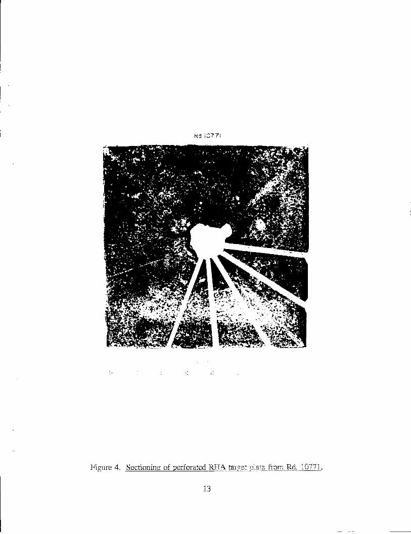
In the case of Rd. 10771, the perforated RHA plate is sectioned into wedges
following the experiment (Figure 4). Microscopy specimens are prepared from thin slices
removed from the exposed faces of the tips of the wedges. Specimens from Rd. 10771 are
mounted in a bakelite resin. In the case of Rds. 4098, 4099 and 4100, witness packs are
disassembled following the experiment, and assorted fragments of RHA are recovered.
Recovered fragments are sectioned to expose an internal surface and mounted in a clear
epoxy. Specimens from the four experiments are then ground, polished, and etched in a
2% nital solution for approximately ten seconds.
Optical microscopy is performed with a Zeiss Axiom at lAC, an inverted reflected
light microscope. The SEM used is a JEOL JXA-840A. Vickers and Rockwell C
hardness measurements are obtained on one fragment specimen by means of a LECO
M -400 microhardness tester.
3. OBSERVATIONS
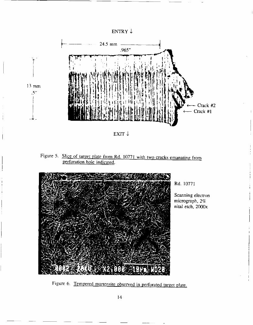
3.1 Perforated RHA Plate from Rd. 10771. Figure 5 shows the slice from the wedge
of Rd. 10771 from which all micrographs in this subsection are obtained. Figure 6 shows
the microstructure of the tempered martensite observed in much of the RHA near the
perforation hole boundary.
Crack # 1 shown in Figure 5, emanating from the hole boundary and inclined at
about 30° to the shot line, is focused upon first.* This crack extends for about 0.75 mm
(Figure 7). It is surrounded by fine-grained material identified as a shear band
* The term crack is used in this report to connote fracture surface. No implication is made about the degree of brittleness or the applicability of a Griffith theory.
3
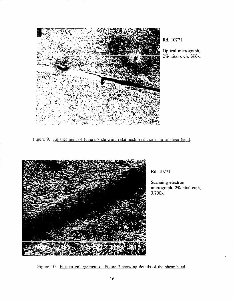
(Figure 8). This shear band continues beyond the tip of the crack. An enlargement of the crack tip region is contained in Figure 9. The four dark spheroidal regions in this
figure are presumably either precipitates or cavities left by the removal of precipitates
during polishing. A scanning electron micrograph of the same shear band at 3,700x magnification reveals its details (Figure 10). The band's width is 6 J..llll. The martensitic laths adjacent to the band show some alignment with the band. Structure in the central
portion of the band is very fine and difficult to resolve in Figure 10.
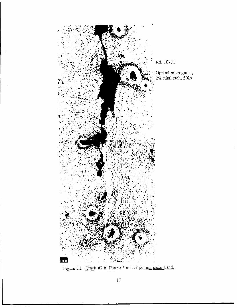
Crack# 2 in Figure 5 is also inclined at about 30° to the shot line. This crack's width varies greatly with distance along its length (Figure 11). It is not bounded by a
fine-grained shear band, as was the first crack. However, a shear band is observed in the vicinity of this second crack's tip.
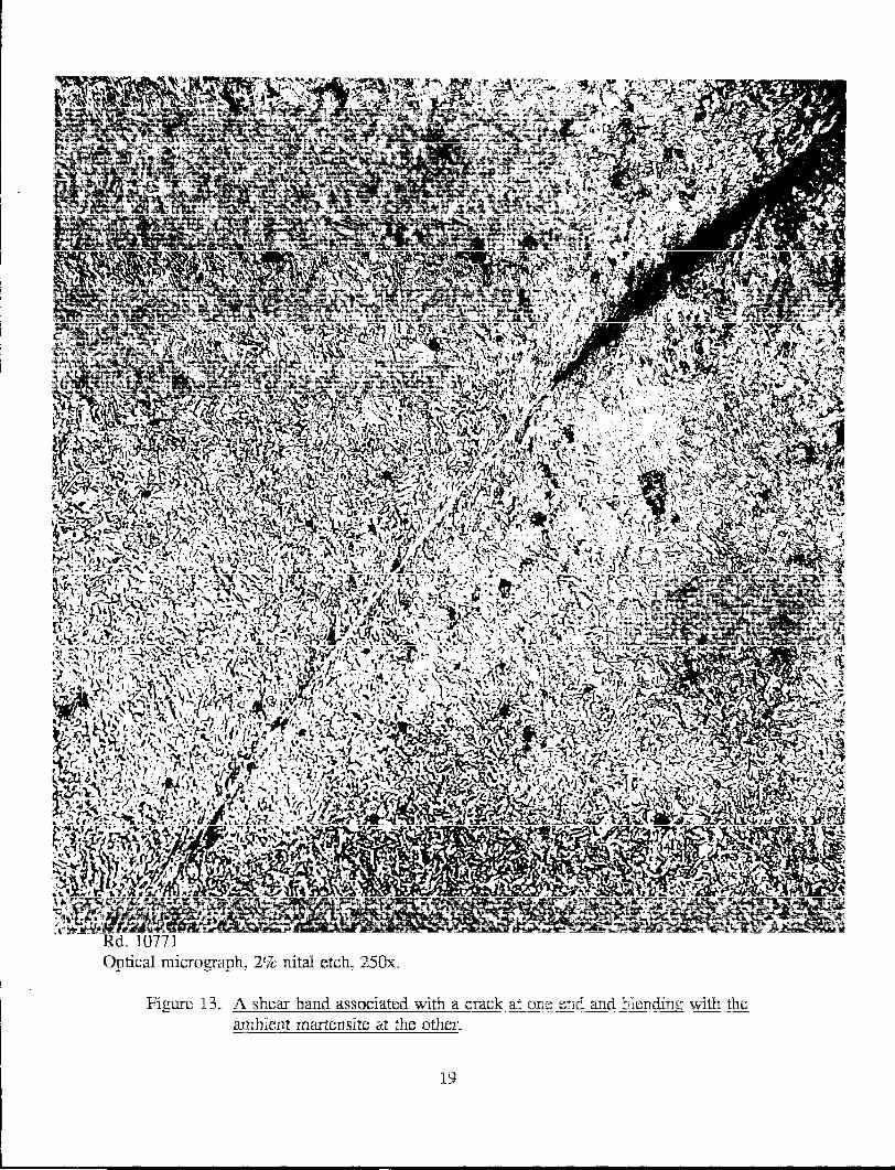
Two additional shear bands within the RHA plate are now examined. Figure 12 contains a scanning electron micrograph of a shear band at a magnification similar to that of Figure 10. In contrast to that previous figure, in Figure 12 the structure within the shear band does not differ so sharply from that of the ambient martensite. Individual laths are seen to enter the shear band. Figure 13 shows a shear band for which one end terminates on a crack, while the other end fans oui and blends into the surrounding
structure.
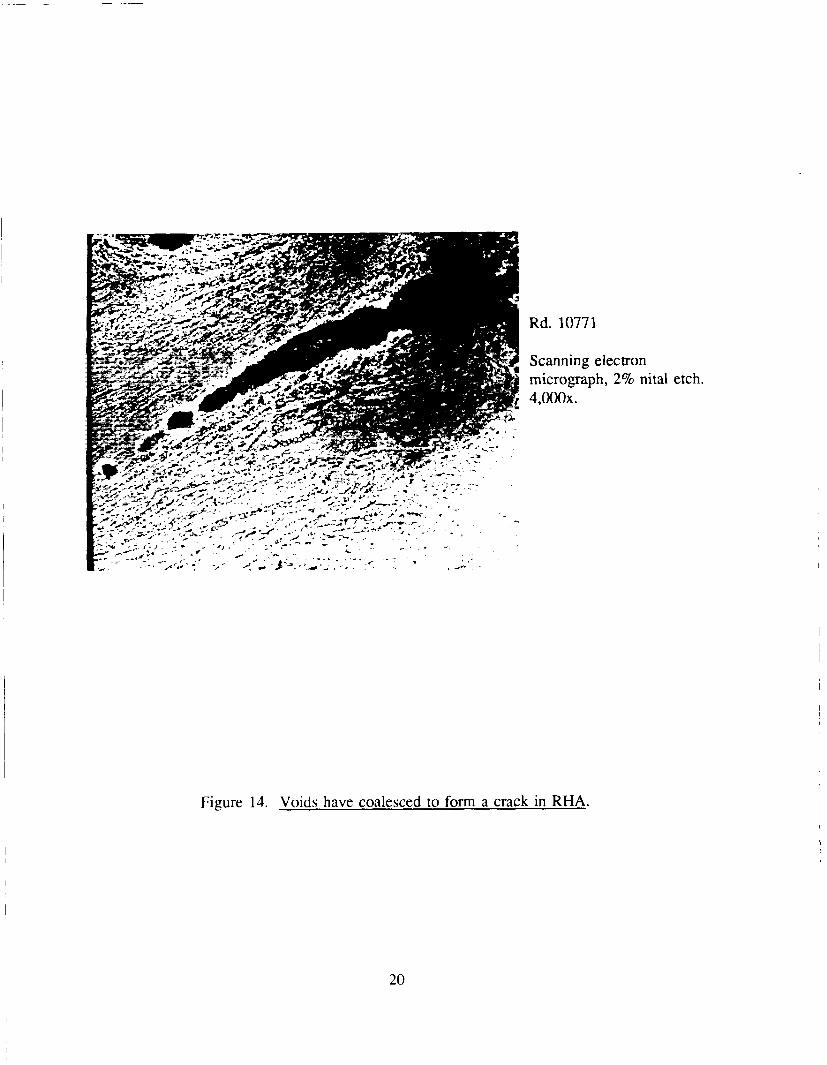
Figure 14 shows a crack that has formed by the coalescence of three voids on the slice shown in Figure 5. These voids range in diameter from 1 to 3 J..llll. Note the local alignment of martensitic laths along the crack.
3.2 RHA Fragments from Rds. 4098. 4099. and 4100. The witness packs from
Rds. 4098, 4099, and 4100 are disassembled following the experiment, and individual fragments are recovered. Figure 15 shows an RHA fragment from Rd. 4099 to be
composed largely of lower bainite. This gives evidence that some RHA material near the path of the jet has undergone a change in microstructure from that of its original tempered martensite.
Figure 16 from Rd. 4098 shows a pattern that is familiar from Rd. 10771. A crack beginning at the fragment's outer surface ends at a straight shear band. As in Figures 7
through 9, much of the crack's boundary in Figure 16 is lined by "white"-etching material. This is probably evidence that the crack propagated into previously shear-banded material.
4
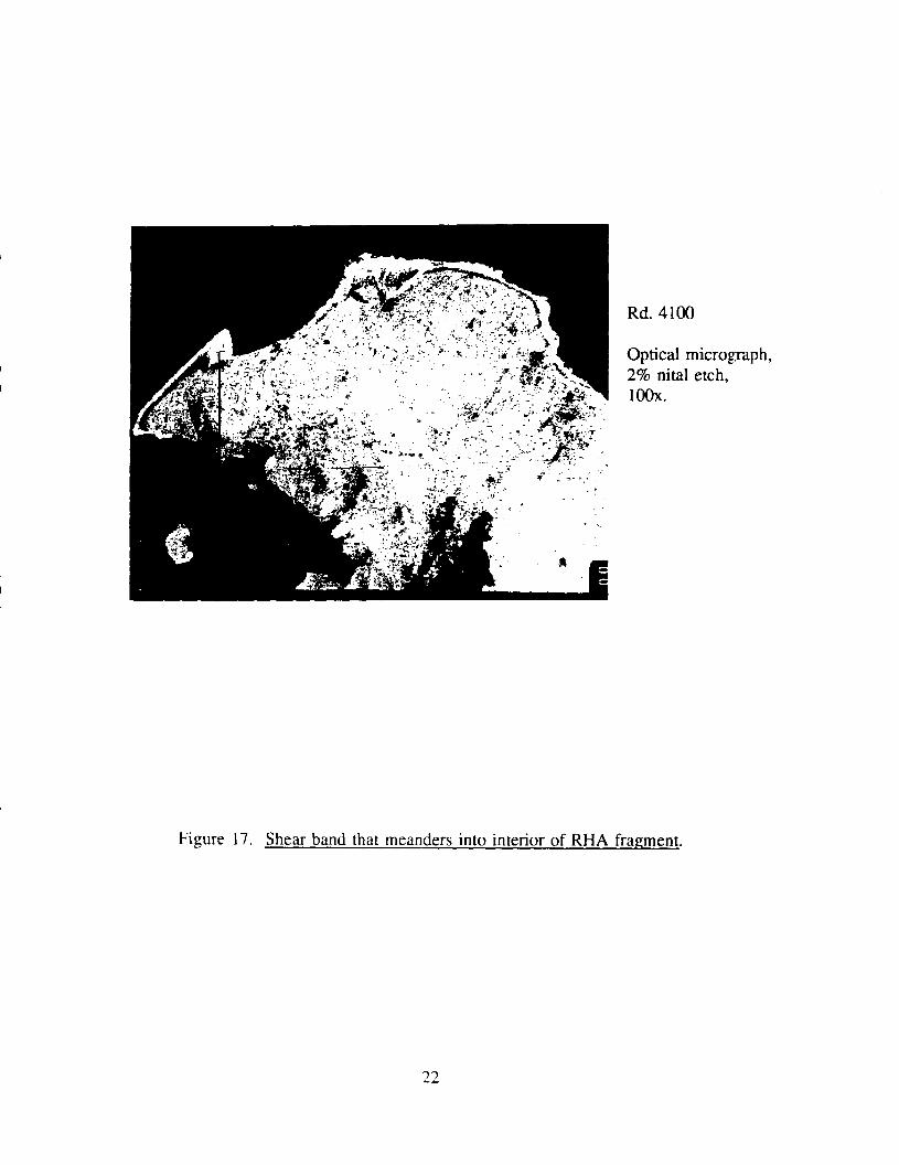
On the other hand, Figure i 7 shows shear bands that are not straight, but instead
meander around the cross section of this fragment from Rd. 4100. Two of these bands
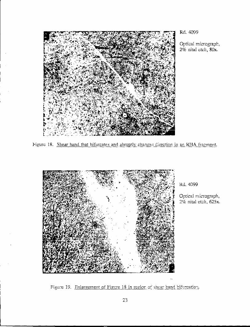
are continuous with a wider shear band that surrounds the fragment. Figure 18 from
Rd. 4099 displays a shear band that both bifurcates and abruptly changes direction. The
band thickens near its bifurcation point. This region is enlarged in Figure 19.
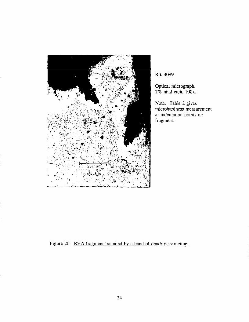
In Figure 20 from Rd. 4099, the fine-grained band near the fragment's periphery
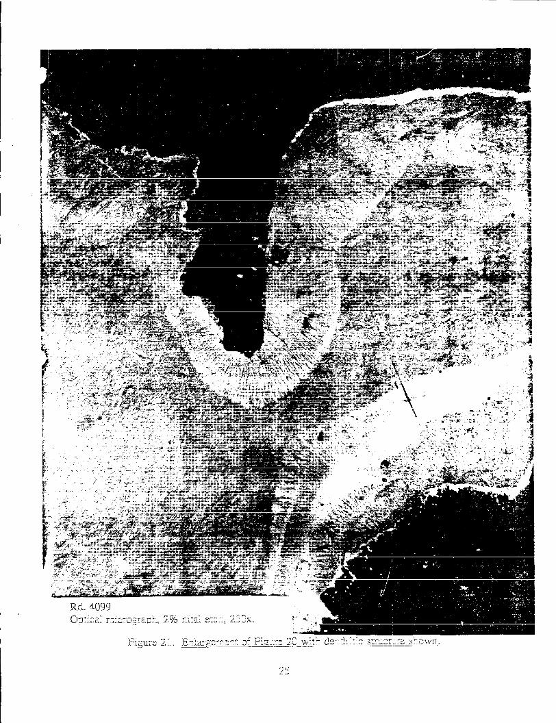
includes a dendritic structure. Figure 21 contains an enlargement. Individual dendrites
are oriented approximately orthogonally to the fragment's local boundary. Vickers and
Rockwell C hardness measurements are made across the fragment. Indentations from the
measurements are visible in Figure 20. Table 2 contains the results. Here VHN and R c
denote Vickers and Rockwell C hardness measurements, respectively. In this table, points
are numbered in the order of increasing distance from the fragment's boundary. Vickers
hardness is seen to increase from a level of about 350 in the ambient RHA to 483 within
the whitened shear band. An intermediate value of 450 is found for the band of
dendrites. The dimension of the indentation exceeds a dendrite's width, so a spatial
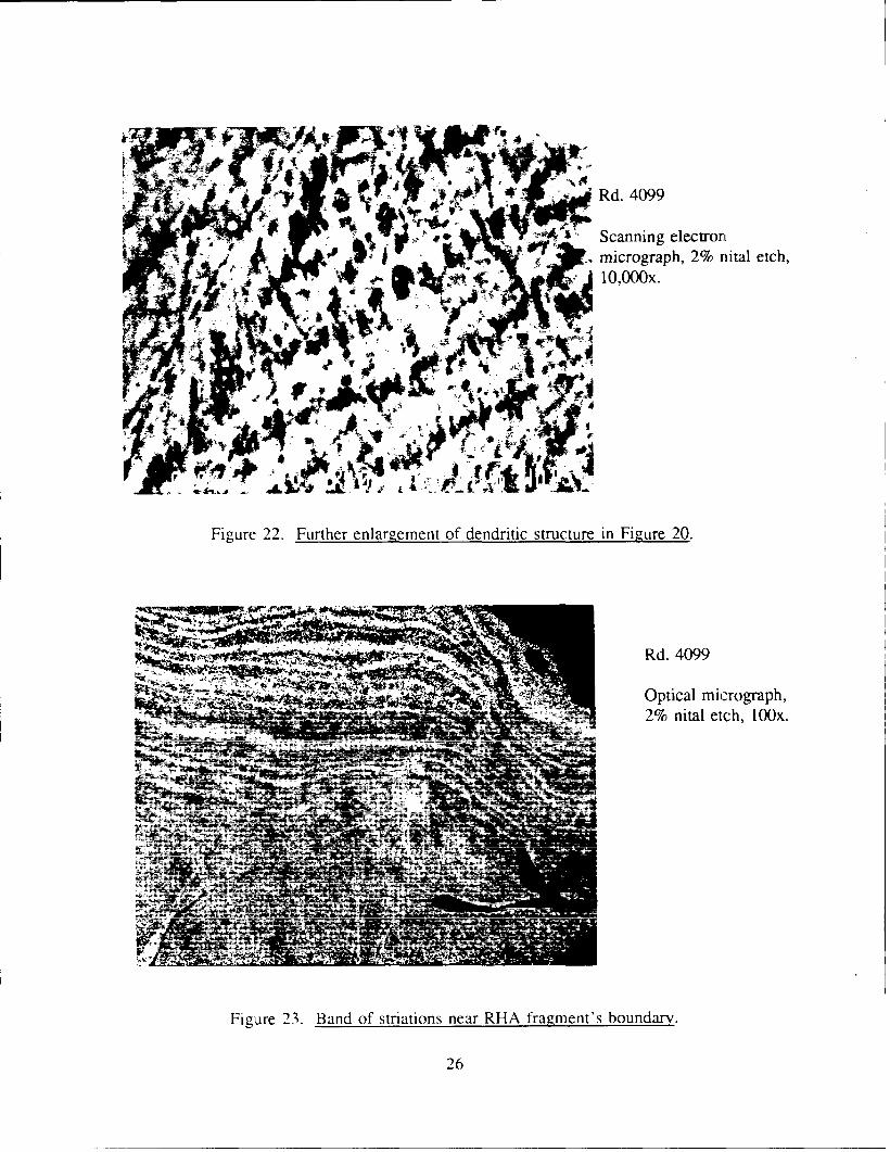
averaging of hardness has occurred in this last measurement. Figure 22 is a scanning
electron micrograph of dendrites at 10,000x magnification.
Figure 23 shows a band of striations that follows the boundary of a fragment from
Rd. 4099. The total width of the band is about 45 Jlll1. This phenomenon appears to be
distinct from both the shear banding and the dendritic structure that have been noted
above.
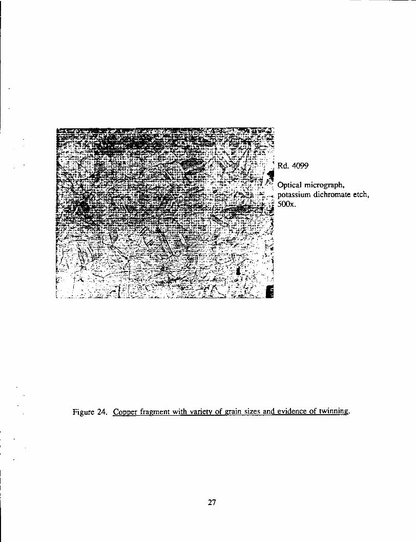
Finally, a single copper fragment from the warhead's liner is shown in Figure 24.
This fragment from Rd. 4099 was etched for 10 seconds in a potassium dichromate
solution. A variety of grain sizes and a large amount of twinning are both evident.
4. DISCUSSION
The observations in Section 3 have included shear bands, voids, cracks, precipitates,
and evidence of changes in martensitic microstructure in RHA and twinning in OFHC
copper. These features probably resulted directly from the target plate perforation,
although it is possible that the witness pack itself inflicted further damage on some
fragments. Each recovered fragment perforated one or more thin sheets of mild steel
within the witness pack.
5
----- -----------------------------------------------------------------------
Cracks have been seen to occur in association with shear bands, as in Figures 7
through 9, 11 and 13, and with void coaslescence, as in Figure 14. The mechanism for
the association in the case of shear bands is not clear and is probably not consistent. One
possibility is the increase in hardness within a shear band relative to that of the
surrounding martensite, which was documented in AISI 4340 steel by Rogers and Shastry
(1981). This hardness increase is presumably accompanied by an increase in brittleness,
thereby lowering the local fracture toughness and predisposing the shear-banded material
to fracture. The above scenario supposes that the shear band preceded the crack.
Various observations in Section 3 will now be placed in the context of some recent
literature. Rogers and Shastry (1981) formed shear bands in 4340 steel and related alloys
by means of impact with flat-nosed projectiles at the relatively low speeds of 0.030 to
0.076 mm/ J.lS. Their observations on shear bands were qualitatively similar to those
described above, which correspond to the much greater projectile velocity of 7.73 mm/ J.lS.
They called fine-structured shear bands that etch "white" in nital, such as the shear band
in Figures 7 through 10, transformed bands. They hypothetized that the steel within such
a band has undergone a sufficient temperature rise to cause re-austenitization, followed by
re-quenching. Rogers and Shastry supported this hypothesis with measurements of
increased microhardness within the band. In fact, they claimed the microhardness in
transformed bands to be greater than that obtainable by a martensitic transformation
brought on by conventional quench and tempering techniques. They attributed the
additional increase in microhardness to the extreme reduction in grain size and the
thorough dissolution of carbon into the hot austenite, followed by carbon precipitation.
This same paper by Rogers and Shastry called shear bands such as that in Figure 12
deformed bands. These "are more ill defined regions of high local shear strain with no
comparable signature of temperature attained." Rogers and Shastry found microhardness
to be much lower here than in the transformed bands. Moreover, they stated that
frequently "deformed bands act as 'precursor bands' to transformed bands," on the basis of
their observations of situations similar to that in Figure 13.
More recent work by Beatty et al. (1990) casts doubt on the assumption by Rogers
and Shastry of local phase transformation within "white"-etching bands, however. Beatty
and co-workers generated shear bands in a hat-shaped specimen of VAR 4340 steel by
means of a split Hopkinson compression bar technique. By use of transmission electron
microscopy (TEM), they obtained selected area diffraction patterns within "white"-etching
bands and in the surrounding martensite. The diffraction pattern was found to vary
6
gradually with distance from the center of the shear band, with no clear discontinuity
occurring at the band's periphery. Also, they were unable to find remaining austenite
within the bands.
Wittman et al. (1990) produced shear bands in a hollow cylinder of AISI 4340 steel
by detonating an explosive charge along its axis. They reported observations similar to
those in Beatty et al. ( 1990): a significant degree of similarity between TEM diffraction
patterns inside and outside the shear band and an absence of austenite within the shear
band. Furthermore, Wittman and co-workers provided a thermal analysis to suggest that
re-austenization within a shear band is avoided because of short time duration (less than
1 ms) at the highest temperatures. Figure 6 of their paper indicates a "white"-etching
shear band width of 6 J..llll, in agreement with Figure 10 of the present report. Also, their
Figure 5 illustrates the phenomenon of shear band bifurcation and bears resemblance to
Figure 18 of the present report.
Thus, results in Beatty et al. ( 1990) and Wittman et al. ( 1990) point to a negative
answer to the question of whether or not re-austenization occurs within a "white"-etching
shear band in RHA. The lower bainite found in the fragment shown in Figure 15 raises
the related question of whether re-austenization occurs in fragmented RHA material that
does not undergo shear banding.
Figure 23 shows striations along a boundary of an RHA fragment. The separation
between adjacent striations is roughly 20 J..llll. The total width of the band of striations
varies along the fragment's boundary, with a typical value of 400 IJIIl. This pattern of
striations is reminiscent of the flow lines which according to Hertzberg (1976) are
produced by the process of mechanical.fibering during forging procedures. He defines
mechanical fibering to be "the alignment of the grain structure in the direction of
mechanical working." On the other hand, the pattern of striations in Figure 23 also bears
resemblance to the reference bands that Moss (1981) observed in an RHA plate prior to
impact. Moss stated that these striations "were planar chemical inhomogeneities that had
been spread through the plate as it was rolled from an ingot. They were extraordinarily
plane and parallel with the flat surfaces of the disc shaped sample." In fact, Moss used
the rotation induced in these striations by penetration of his specimen by a punch as a
measure of the shear strain field in the specimen. Thus, the question of whether the
striations in Figure 23 were created by the deformation associated with perforation or
instead were pre-existent in the plate prior to impact and merely distorted by the
7
deformation cannot be resolved at this time. However, in favor of the former possibility
are the facts that the band of striations in Figure 23 only occurs along the boundary of
the fragment shown and that no such pattern is observed in any other specimens prepared
from the target plate of Rd. 10771 or recovered fragments from Rds. 4098, 4099, and
4100.
The evidence of spheroidal precipitates that has been noted in Figure 9 can perhaps
be identified with the carbon-rich precipitates noted in Glass and Bruchey (1987).
Honeycombe (1981) discusses "coarse spheroidized particles of Fe3C" (cementite) that are
found in martensite tempered at above 620 K. The rather large 5-f..Uil dimension of these
particles suggests that they more likely formed during the original tempering of the target
plate rather than subsequently as a result of the plate's penetration.
The twins observed in the copper specimen of Figure 24 appear to illustrate the
phenomenon of annealing twins that is described in Meyers and Chawla ( 1984). There
annealing twins are said to be common in FCC metals and are defined as twins that are
"formed during heat treatment (recovery, recrystallization, and grain growth)," rather
than as a direct result of mechanical shearing deformation. In the present context, the
copper was subjected to intense temperature rise associated with the processes of liner
collapse and target interaction, followed by quenching at ambient temperature.
This report has documented isolated observations of microstructural phenomena in
RHA material that has undergone perforation by a shaped charge jet. The relevance to
this problem of laboratory experiments performed at relatively low strain rates can be
judged by determining whether similar phenomena are present. A complete overview of
the likelihood of occurrence of shear banding, cracking, void formation, and phase
transformation in a perforated plate as functions of position and time has yet to emerge,
however. Such an overview on the micromechanicallevel would be very useful to those
modelers attempting to treat this problem in detail.
8
Rd.
4098
4099
4100
10771
Table 1. Round Descriptions
Date Range d BHNent. BHNexit X-sect.
(mm) (mm2)
21106/89 16 25.5 364 364 254x256
22/06/89 16 12.5 364 340 251x252
23/06/89 16 25.6 364 340 251x252
9111/88 7A 13.0 364 364 197x197
Table 2. Vickers and Rockwell C Hardness Measurements Across
the RHA Fragment of Figures 20, 21, and 22
(100 g Load Used)
Pt. VHN Rc Comments
1 373 38.0 two-phase region
2 429 43.5 two-phase region
3 464 46.5 on white shear band
4 483 48.0 on white shear band
5 450 45.3 on dendrite arms
6 450 45.3 on dendrite arms
7 363 36.8 martensite matrix
8 363 36.8 martensite matrix
9 363 36.8 martensite matrix
10 345 35.0 martensite matrix
11 333 33.5 martensite matrix
12 351 35.6 martensite matrix
9
s (C.D.)
3.00
3.00
12.00
15.23
X-RAY TUBES
SHAPED CHARGE CONICAL OFHC COPPER LINER
\ ·l-- - -- - -- - - - f ---
STANDOFF S
DIA. 81.3mm • I C.D. l CHARGE
-----------~'::: :: :: :I: RHA TARGET PLATE
.----254mm -----t~ X-RAY FILM
TARGET PLATE
THICKNESS d
609.6mm
~-----------------------------~-----
WITNESS PACK
.... -------1219mm ----------~
(NOT TO SCALE)
Figure 1. Setup for range firings.
10
,_, :--.-~\
Hds. 409£) & 4186
t o-:c 4 us I
r l
t . 7 '? n l r C' , · t L.~ >< 1
• ~J
T~rnes RelAtive to lfrTlf1 of lniti;!i lr11p:1r r
t= 17.7ps
t c- 1 42' 1 p fi
l,li!l
'
. '
-~
'~~ .. :
t
-~'~ \1( ,~·,;· "' • !'I """_.. 4 "'
.rc•:\•.~.::" .rr • . )~ r ... · I. 'l
t .. 212.2 ,u;;
l"igu.re 2. Pm·impa~t and po!<lt·pmfomtitm racliograiJh~ for a ~tandnff of 3.00 C.D. and a target plate thicknc:-;~ of 13 mnL
-+-~-' j
Figure 3. Pre~impact radiograph from Rd. 4100.
12
Rd 1077'f
Figure 4. Sectionine: of perforated RHA tru·p:c:;_J5~.J:l1J~Jjnrn Rd._]077l_.
,. ,, J.J
13 mm
.5"
ENTRY -1-
EXIT l
Figure 5. Slice of target plate from Rd. 10771 with two cracks emanating from perforation hole indicated.
Rd. 10771
Scanning electron micrograph, 2% nital etch, 2000x
Figure 6. Tempered martensite observed in perforated target plate.
14
... .. ""' ·~·
.,;1 •
•
... ~---
·-
.·
'j
• •
.-.·-.....
• •
;::;~._-~;~
. ~ 1:· ·~ "" ...
Rd. 10771
Optical micrograph, 2% nital etch, 80x
Figme 7. Crack #1 in Fie:ure 5 and adjoi.::J.h:£_shear band.
Optical micrograph, 2% nital etch, 500x
Figme 8. ;Enlargement of Fie:ure 7 showir.e: crack ~:o ·~e s;1:::munded. bv a shear band.
Rd. 10771
Optical micrograph, 2% nital etch, 800x.
Figure 9. Enlargement of Figure 7 showing relationship of crack tip to shear band.
Rd. 10771
Scanning electron micrograph, 2% nital etch, 3,700x.
Figure 10. Further enlargement of Figure 7 showing details of the shear band.
16
~ . :: ::J.~.~~~·:::,::~;) - .... • .. ,_.} ---
~..,_. ~·--- ...
~f}??i:, ... ~/·.-- ;lj ·~~. ' .... ~~: __ _.....,\.
~.'~- J~·- -'=;J:~ ..... J .. f~
t ... /-: .. ·_ :: ~ 4:', /. ',.~ '. _.Y, .. ..;..
~~:N 1:~.,~·J'f ,., "" :r .. --~
( -; ,--:... ...
/" ' :~ l
.,r ·~ ~
-~ . . . -~-7:,; -t
~-_..Y~~~-J!
' .
-,.,.· '-,
Rd. 10771
Optir::al micrograph, 2% nital etch, 500x.
Figure 1 L Crack #2 in Figure 5 and ad}ohtin£ shear band.
17
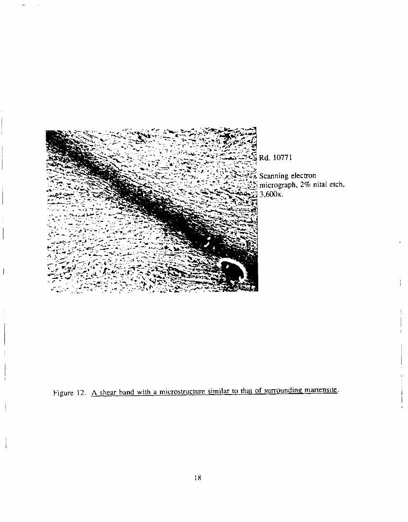
Figure 12. A shear band with a microstructure similar to that of surrounding martensite.
18
Optical mic..1ograph, 2r1t: nital etch, 250x.
Figure 13. A shear band associated with a crack at on~ end and blendine: wit:h the ambient martensite at the other.
19
Rd. 10771
Scanning electron micrograph, 2% nital etch. 4,000x.
Figure 14. Voids have coalesced to form a crack in RHA.
20
Rd" 4099
Optical micrograph, 2% nital etch, l,()()Qx.
Figure 15. Lower bainite microstructure in RHA fra£::nent.
·l-; .•
~· .. · ·~-· ' ·~ .. ·- ' ' --:~ ··- ... · .. ; -~ . ,. -~
:-;~---. . ' ' ~
.... , _...,., .. -
-·.
' . . . "· .
. ..
...
Rd. 4098
Optical micrograph, 2% nital etch, 80x.
Figu:re 16. Crack at boundarv of RHA fra2:ment !!-ltd adjoini:1K shear band ..
21
Rd. 4100
Optical micrograph, 2% nital etch, lOOx.
Figure 17. Shear band that meanders into interior of RHA fragment.
22
Rd. 4099
Optical micrograph, 2% nita! etch, 80x.
Figure 18. Shear band that bifurcates and abruptlv chane:e; direction in an RHA fragment.
Rd. 4099
Optical Inicrograph, 2% nital et~h, 625x.
:Figure 19. J<:.nlare:ement of Fie:ure 18 in re2:ior. o•:· r;):lear band bifurcation.
23
'·· ~ ~· ' . •I, -
.. ._.........;.1-.; •• ";··.
. :': ..... ...
.• ,:0' •
., .. ~
Rd. 4099
Optical micrograph, 2% nital etch, lOOx.
Note: Table 2 gives microhardness measurement at indentation points on fragment.
Figure 20. RHA fragment bounded by a band of dendritic structure.
24
Rd. 4099
Scanning electron micrograph, 2% nital etch, lO,OOOx.
Figure 22. Further enlargement of dendritic structure in Figure 20.
Rd. 4099
Optical micrograph, 2% nital etch, 1 OOx.
Figure 23. Band of striations near RHA fragment's boundary.
26
~Rd. 4099
Optical micrograph, I potassium dichromate etch,
500x.
Figure 24. Copper fragment with variety of grain sizes and evidence of twinning.
27
INTENTIONALLY LEFr BLANK.
28
5. REFERENCES
Beatty, J. H., L. W. Meyer, M.A. Meyers, and S. Nemat-Nasser. "Formation of Controlled Adiabatic Shear Bands in AISI 4340 High Strength Steel." MTL-TR-91-4, U. S. Army Materials Technology Laboratory, Watertown, MA, 1990.
Glass. J. T .. and W. J. Bruchey, Jr. "Internal Deformation and Energy Absorption During Penetration of Semi-Infinite Targets." Journal of Ballistics, 9, pp. 2443-2468, 1987.
Hertzberg, R. W. Deformation and Fracture Mechanics of Engineering Materials, Wiley, New York, pp. 121-124, 1976.
Honeycombe, R. W. K. Steels, Microstructure and Properties, Edward Arnold, London, pp. 144-146, 1981.
Meyers. M.A., and K. K. Chawla. Mechanical Metallurgy, Principles and Applications, Prentice-Hall, Englewood Cliffs, N J, pp. 289-291, 1984.
Moss, G. L. "Shear Strains, Strain Rates and Temperature Changes in Adiabatic Shear Bands." Shock Waves and High-Strain-Rate Phenomena in Metals, edited by M.A. Meyers and L. E. Murr, Plenum Press. New York. pp. 299-312, 1981.
Raftenberg, M. N. "Modeling RHA Plate Perforation by a Shaped Charge Jet." BRL-TR-3363, U. S. Army Ballistic Research Laboratory, Aberdeen Proving Ground, MD, 1992.
Raftenberg, M. N. "Experimental Investigation of Rolled-Homogeneous-Armor Plate Perforation by a Shaped Charge Jet." U. S. Army Research Laboratory, Aberdeen Proving Ground, MD, to be published.
Raftenberg, M. N., and C. D. Krause. "RHA Plate Perforation by a Shaped-Charge Jet: Experiment and Hydrocode Simulation." Shock-Wave and High-Strain-Rate Phenomena in Materials, edited by M. A. Meyers, L. E. Murr and K. P. Staudhammer, Marcel Dekker, New York, pp. 555-564, 1992.
Rogers, H. C., and C. V. Shastry. "Material Factors in Adiabatic Shear Bands in Steels." Shock Waves and High-Strain-Rate Phenomena in Metals, edited by M.A. Meyers and L. E. Murr, Plenum Press, New York, pp. 285-298, 1981.
U. S. Department of Defense. "Military Specification: Armor Plate, Steel, Wrought, Homogeneous (for Use in Combat-Vehicles and for Ammunition Testing)." MIL-A-12560G(MR), U. S. Army Materials Technology Laboratory, Watertown, MA, 1984.
Wittman, C. L., M.A. Meyers, and H.-r. Pak. "Observations of an Adiabatic Shear Band in AISI 4340 Steel by High-Voltage Transmission Electron Microscopy." Metallurgical Transactions A, 21A. pp. 707-716, 1990.
29
INTENTIONALLY LEFT BLANK.
30
No. of No. of Copies Organization Copies Organization
2 Administrator 1 Commander Defense Technical Info Center U.S. Army Missile Command ATTN: DTIC-DDA ATIN: AMSMI-RD-CS-R (DOC) Cameron Station Redstone Arsenal, AL 35898-5010 Alexandria, VA 22304-6145
1 Commander 1 Commander U.S. Army Tank-Automotive Command
U.S. Army Materiel Command ATIN: ASQNC-T AC-DIT (Technical ATTN: AM CAM Information Cenrer') 5001 Eisenhower Ave. Warren, MI 48397-5000 Alexandria, VA 22333-0001
1 Director 1 Director U.S. Army TRADOC Analysis Command
U.S. Army Research Laboratory ATIN: ATRC-WSR ATTN: AMSRL-OP-CI-AD, White Sands Missile Range, NM 88002-5502
Tech Publishing 2800 Powder Mill Rd. 1 Commandant Adelphi, MD 20783-1145 U.S. Army Field Artillery School
ATIN: ATSF-CSI 1 Director Ft Sill, OK 73503-5000
U.S. Army Research Laboratory ATTN: AMSRL-OP-CI-AD, (Cius. only) 1 Commandant
Records Management U.S. Army Infantry School 2800 Powder Mill Rd. ATTN: ATSH-CD (Security Mgr.) Adelphi, MD 20783-1145 Fort Benning, GA 31905-5660
2 Commander (Undua. only) 1 Commandant U.S. Army Armament Research, U.S. Army Infantry School
Development, and Engineering Center ATTN: ATSH-CD-CSO-OR ATTN: SMCAR-IMI-1 Fort Benning, GA 31905-5660 Picatinny Arsenal, NJ 07806-5000
1 Wl./MNOI 2 Commander Eglin AFB, Fl.. 32542-5000
U.S. Army Armament Research, Development, and Engineering Center Aberdeen Proving Ground
ATTN: SMCAR-TDC Picatinny Arsenal, NJ 07806-5000 2 Dir, USAMSAA
ATIN: AMXSY-D 1 Director AMXSY-MP, H. Cohen
Benet Weapons Laboratory U.S. Army Armament Research, 1 Cdr, USATECOM
Development, and Engineering Center ATTN: AMSTE-TC ATTN: SMCAR-CCB-TL Watervliet, NY 12189-4050 1 Dir, ERDEC
ATTN: SCBRD-RT (Uncl11111. only) 1 Commander
U.S. Army Rock Island Arsenal 1 Cdr, CBDA ATTN: SMCRI-IMC-RT(fechnical Library ATTN: AMSCB-CI Rock Island, IL 61299-5000
1 Dir,USARL 1 Director ATTN: AMSRL-SL-1
U.S. Army Aviation Research and Technology Activity 10 Dir,USARL
ATTN: SAVRT-R (Library) ATIN: AMSRL-OP-CI-B (Tech Lib) MIS 219-3 Ames Research Center Moffett Field, CA 94035-1000
31
No. of Copies Organization
5
1
1
8
1
Director U.S. Army Research Office A TIN: J. Chandra
J. Wu K. lyer A. Crowson Technical Library
P.O. Box 1211 Research Triangle Park, NC 27709-2211
Director U.S. Army Research Laboratory ATIN: AMSRL-D-TO,
Clarence W. Kitchens, Jr. Adelphi, MD 20783-1145
Commander U.S. Army Research and Standardization
Group (Europe) A 1TN: F. Oertel P.O. Box 65 FPONY 09510
Director U.S. Army Research Laboratory- Materials
Directorate ATIN: AMSRL-MA,
G. Bishop S. Chou J. Dandekar A. Rajendran T. Weerasooriya M. Wells J. Beatty Technical Library
Watertown, MA 02172-0001
Commander U.S. Army Tank-Automotive Command ATIN: AMSTA-RSK, J. Thompson Warren, MI 48397-5000
1 U.S. Naval Academy Department of Mathematics ATIN: R. Malek-Madani Annapolis, MD 21402
32
No. of Copies Organization
1 Air Force Wright Aeronautical Laboratories Air Force Systems Command Materials Laboratory ATIN: T. Nicholas Wright-Patterson AFB, OH 45433
4 Commander U.S. Army Armament Research, Development,
and Engineering Center ATIN: SMCAR-AEE-WW, E. Baker
SMCAR-AET-M, F. Witt C. Feng Technical Library
Picatinny Arsenal, NJ 07806-5000
2 Commander U.S. Army Missile Command ATIN: AMSMI-RD, W. Jennings, Jr.
AMSMI-RD-ST-WF, M. Schexnayder Redstone Arsenal, AL 35898
1 Commander
4
3
U.S. Army Tank-Automotive Command Armor Application Section ATIN: AMSTA-RSK, S. Goodman Warren, MI 48397-5000
Director Wright Laboratory A1TN: WL/MNMW, J.A. Collins
MNW, W. Cook WL/MNMW, J. Foster, Jr. Technical Library
Eglin Air Force Base, FL 32542-5434
Commander Naval Surface Warfare Center A TIN: Technical Library
W. Mock W. H. Holt
Dahlgren, VA 22448
No. of No. of Copies Organization Copies Organization
5 Commander 1 Commander Naval Weapons Center Naval Postgraduate School ATTN: Code 3266, R. Hoffmann ATTN: Code 73, J. Sternberg
Code 3261, T. Gill Monterey, CA 93943 S. Finnegan J. C. Schulz 12 Director Technical Library Sandia National Laboratories
China Lake, CA 93555-6001 ATTN: D. Grady M. Kipp
5 Commander W. Herrmann Naval Surface Warfare Center S. Passman ATTN: F. Zerilli M. Forrestal
H. Chen, U12 V. Luk H. Mair, R12 L. Davison C. S. Coffey P. Yarrington Technical Library S. A .. Silling
Silver Spring, MD 20903-5000 J. M McGlaun E. Hertel
1 Commander M. M. Hightower Naval Research Laboratory P.O. Box 5800 ATTN: J. A. Nemes Albuquerque, NM 87185-5800 Washington, DC 20375
1 Director 1 Director Sandia National Laboratories
Defense Advanced Research Projects ATTN: D. Bammann Agency Livermore, CA 94550
ATTN: J. Richardson Armor/Antiarmor Joint Program Office 1 National Institute of Science and Rosslyn, VA 22209-2308 Technology
ATTN: T.Burns 2 Director Technology Building, Rm A151
Defense Advanced Research Projects Gaithersburg, MD 20899 Agency
ATTN: B. Wilcox 11 Director Tech. Info. Lawrence Livermore National Laboratory
3701 North Fairfax Dr. ATTN: L-38, M. Finger Arlington, VA 22203-1714 L-122, B. Bowman
L-35, 1 Director R. Couch
Defense Advanced Research Projects R. Tipton Agency D. Baum
Land Systems Office D. Steinberg ATTN: T. Phillips 1. Reaugh 3701 North Fairfax Dr. L342, D. Lassila, Arlington, VA 22203-1714 G. Goudreau
W. H. Gourdin 1 Office of Munitions Technical Library
ATTN: OUSD(A){fWD/OM, A. Holt P.O. Box 808 Room 3B1060, The Pentagon Livermore, CA 94550 Washington, DC 20301
33
No. of Copies Organization
16 Director Los Alamos National Laboratory ATIN: J. Chapyak
MS F663, J.Johnson S. K. Shiferl T. F. Adams D. A. Mandell P. Follansbee
MS J960, R. Karpp L.Hull
MS B216, J. W. Hopson MS B295,
K. Holian G. T. Gray
MS K765, S. R. Chen MS G787, G. E. Cort, J. Repa A. K. Zurek Technical Library
P. 0. Box 1663 Los Alamos, NM 87454
1 Brown University Division of Engineering A TIN: R. Clifton Providence, RI 02912
1 University of California at Santa Barbara
Department of Materials Science ATIN: A. Evans Santa Barbara, CA 93106
4 University of California at San Diego
Department of Applied Mechanics and Engineering Sciences
A TIN: R. Asaro K. Vecchio M. Meyers S. Nemat-Nasser
La Jolla, Ca 92093
2 California Institute of Technology ATIN: W. Knauss
G. Ravichandran Mail Code 105-50 Pasadena, CA 91125
34
No. of Copies Organization
1 Michigan Technological University Dept of Mechanical Engineering ATIN: W. W. Predebon 1400 Townsend Dr. Houghton, Ml 49931-1295
1 Cornell University Department of Theoretical and
Applied Mechanics ATIN: J. Jenkins Ithaca, NY 14850
2 Drexel University Department of Materials Engineering A TIN: H. Rogers
P. Chou Philadelphia, PA 18104
1 Harvard University Division of Engineering and
Applied Physics ATIN: J. Hutchinson Cambridge, MA 02138
1 University of IUinois Department of Theoretical and
Applied Mechanics ATIN: T. Shawki Urbana, IL 61801
3 The Johns Hopkins University Department of Mechanical Engineering Latrobe Hall A TIN: A. Douglas
K. Ramesh W. Sharp
34th and Charles Streets Baltimore, MD 21218
2 University of Maryland Department of Mechanical Engineering ATIN: R. Armstrong
J. Dally College Park, MD 20742
1 University of Maryland Baltimore County A TIN: A. Khan Baltimore, MD 21228
No. of No. of Copies Organization Copies Organization
1 Massachusetts Institute of 1 Texas A&M University Technology Aerospace Engineering Department
Deparunent of Mechanical Engineering ATIN: T. Strouboulis ATIN: L. Anand College Station, TX 77843-3141 Cambridge, MA 02139
1 Washington State University 1 University of Missouri-Rolla Deparunent of Mechanical and
Deparunent of ME, AE & EM Materials Engineering ATIN: R. Batra ATIN: H. Zbib Rolla, MO 65401-0249 Pullman, WA 99164
1 State University of New York 1 Institute for Defense Analysis at Stony Brook ATIN: G. Mayer
Deparunent of Applied Mathematics 1801 N. Beauregard Street and Statistics Alexandria, VA 22311
ATIN: J. Glimm Stony Brook, NY 11794 4 SRI International
ATIN: D. Curran 1 North Carolina State University R. Shockey
Deparunent of Mechanical and L. Seaman Aerospace Engineering H. Giovanola
ATIN: M. Zikry 333 Ravenswood Avenue Raleigh, NC 27695 Menlo Park, CA 94025
1 Northwestern University 3 Southwest Research Instiwte Deparunent of Applied Mathematics Department of Mechanical Sciences ATIN: W. Olmstead ATIN: C. Anderson Evanston, IL 60208 J. Lankford
U. Lindholm 1 Northwestern University 8500 Culebra Road
Deparunent of Civil Engineering San Antonio, TX 02912 ATIN: T. Belytschko Evanston, IL 60208 1 Baltimore Gas and Electric Company
ATIN: Ms. Claire D. Krause 1 Rensselaer Polytechnic Instiwte Fort Smallwood Road Complex
Deparunent of Mechanical Engineering 1000 Brandon Shores Road ATIN: E. Krempl Baltimore, MD 21226 Troy, NY 12181
1 California Research and 1 Rensselaer Polytechnic Instiwte Technology, Inc.
Department of Computer Science ATIN: D. Orphal ATIN: J. Flaherty 5117 Johnson Dr. Troy, NY 12181 Pleasanton, CA 94566
I University of Texas 2 General Research Corporation Texas Instiwte for Comp. Mechanics ATIN: A. Charters ATIN: J. Oden T.Menna Austin, TX 78712 5383 Hollister Ave.
Santa Barbara, CA 93111
35
No. of Copies Organization
3 Alliant Techsystems, Inc. ATTN: G. Johnson
T. Holmquist C. L. Witbnan
7225 Northland Dr. Brooklyn Park, MN 55428
1 Research & Development Associates ATTN: J. Furlong 2100 Washington Blvd. Arlington, VA 22209
1 Aluminum Company of America ATTN: R. Stemler ALCOA Center, PA 15069
2 E.I. DuPont de Nemours ATTN: M. Bernhardt,
B. Scott P.O. Box 80702 Wilmington, DE 19880
1 General Dynamics Land Systems Division ATTN: W. Burke P.O. Box 1800 Warren, MI 48090
2 Kaman Sciences Corporation ATTN: J. May
M. Normandia P.O. Box 7643 Colorado Springs, CO 80933
2 California Research and Technology, Inc.
ARAP Group - A Titan Company ATTN: R. Thorpe
M. Majerus P.O. Box 2229 Princeton, NJ 08543-2229
1 Battelle Ordnance Systems and Technology
Department ATTN: D. Butz 505 King Ave. Columbus, OH 43201-2693
36
No. of Copies Organization
2 Battelle Edgewood Operations ATTN: R. Jameson
S. Golaski 2113 Emmorton Park Rd. Edgewood, MD 21040
1 GTE Products Corporation Chemical and Metallurgical Division ATTN: J. Gonzalez Hawes St Towanda, PA 18848
1 Teledyne-Brown Engineering ATTN: L. Smalley, MS50 P.O. Box 07007 Huntsville, AL 35807-7007
1 Failure Analysis Associates ATTN: S. Andrew P.O. Box 3015 Menlo Park, CA 94025
2 Lanxide Armor Products, Inc. ATTN: V. Kelsey
K. Leighton P.O. Box 6077 Newark, DE 19714-6077
1 Dyna East Corporation ATTN: W. Flis 3201 Archer St. Philadelphia, PA 19104
1 Institute for Advanced Technology ATTN: S. Bless 4030-2 W. Braker Lane Austin, TX 78759-5329
1 Zemow Technical Services, Inc. ATTN: L. Zernow 425 West Benita, Suite 208 San Dimas, CA 91773
1 Orlando Technology, Inc. ATTN: D. Matuska P.O. Box 855 Shalimar, FL 32579
No. of Copies Organization
1 Denver Research Institute ATIN: J. D. Yatteau P.O. Box 10127 Denver, CO 80210
1 Livennore Software Technology Corporation
ATIN: J. Hallquist 2876 Waverly Way Livennore, CA 94550
1 University of Illinois Dept of Metallurgy
and Mineral Engineering ATIN: H.-r. Pale Urbana, ll.. 61801
37
No. of No. of Copies Organization Copies Organization
1 Ruhr-Universitat Bochum 1 Ernst-Mach Institut ATIN: J. Kalthoff ATIN: A. Stilp Universitatstrasse 150 Eckerstrasse 4 4360 Bochum 1, Postfach 102148 D-7800 Freiburg i. Br. GERMANY GERMANY
1 Condat GmbH 1 IABG ATIN: K. Thoma ATIN: H. Raatschen Maximilianstrasse 28 Einsteinstrasse 20 8069 Scheyem-Femhag D-8012 Ottobrun B. Muenchen GERMANY GERMANY
1 IFAM 1 Centre d 'Etudes de Vajours Materialforschung ATIN: PLOT ARD J.-P. ATIN: L. Meyer Boite Postale No. 7 Lesumer Heerstrasse 36 77181 Country 2820 Bremen 77 FRANCE GERMANY
1 PRB S.A. 2 RARDE ATIN: M. Vansnick
ATIN: I. Collis Avenue de Tervueren 168, Bte. 7 A. Hopkins Brussels, B-1150
Fort Halstead - Sevenoaks BELGIUM TN14 7BP Kent ENGLAND 1 AB Bofors/Ammunition Division
ATIN: Jan Hasslid 1 Defence Research Establishment Box 900
Suffield S-691 80 Bofors ATIN: C. Weickert SWEDEN Ralston, Alberta, TOJ 2NO Ralston CANADA 1 Materials Research Laboratories
ATIN: R. L. Woodword 1 Defence Research Establishment P.O. Box 50
Valcartier Ascot Vale ATIN: N. Gass Victoria 3032 P.O. Box 8800 AUSTRALIA Courcellette, PQ, GOA 1RO CANADA 1 E. Risch
MIL P.O. Box 02128 1 Canadian Arsenals, LTD ISRAEL
ATIN: P. Pelletier 5 Montee des Arsenaux 1 Y. Kivity Villie de Gardeur, PQ, JSZ2 Rafael Ballistics Center CANADA Haifa
ISRAEL 1 Centre d'Extudes de Gramat
ATIN: Solve, G. 46JO Grarnat FRANCE
38
USER EVALUATION SHEET/CHANGE OF ADDRESS
This Laboratory undertakes a continuing effort to improve the quality of the reports it publishes. Your comments/answers to the items/questions below will aid us in our efforts.
1. ARL Report Number __ ARL __ -MR_-_6_8 _______ Date ofReport_J_u_n_e_l9_9_3 ____ _
2. DateReportReceived __________________________ _
3. Does this report satisfy a need? (Comment on purpose, related project, or other area of interest for
which the report will be used.)-------------------------
4. Specifically, how is the report being used? (lnfonnation source, design data, procedure, source of ideas, etc.) _______________________________ _
5. Has the infonnation in this report led to any quantitative savings as far as man-hours or dollars saved,
operating costs avoided, or efficiencies achieved, etc? If so, please elaborate. ---------
6. General Comments. What do you think should be changed to improve future reports? (Indicate changes to organization, technical content, fonnat, etc.)-----------------
Organization
CURRENT Name ADDRESS
Street or P.O. Box No.
City, State, Zip Code
7. If indicating a Change of Address or Address Correction, please provide the Current or Correct address above and the Old or Incorrect address below.
Organization
OLD Name ADDRESS
Street or P.O. Box No.
City, State, Zip Code
(Remove this sheet, fold as indicated, tape closed, and mail.) (DO NOT STAPLE)
DE?ARTMENT OF THE ARMY
OFRCIAL BUSINESS BUSINESS REPLY ~LUL ARST cuss FfRMIT Ill 0001 I APG, MD
Postage will be paid by addressee.
Director U.S. Army Research Laboratory ATIN: AMSRL-OP-Cl-8 (Tech Lib) Aberdeen Proving Ground, MD 21005-5066
NO POSTAGe NECESSARY
IF MAILED IN THE
UNITED SiATES
l
•