Embed Size (px)
Citation preview
Metallic Materials Development for Solid Oxide Fuel Cells
J. Dunning, J. Hawk, D. Alman, P. Jablonski, G. Holcomb, M. Ziomek-Moroz, S. Cramer, A. Petty
and R. Walters
Albany Research CenterAlbany, OR, 97321 www.alrc.doe.gov
SECA Core Technologies Peer Review WorkshopTampa Bay, Florida, January, 27-28, 2005
SECA CTP Review MeetingTampa Bay, FL, January 27-28, 2005
Outline
1. Low CTE Nickel Base Alloys (J.Dunning)• Composition• Production of Strip
2. Modifications for Improved Oxidation Resistance (J. Dunning)
• Nickel-Base and Ferritic Alloys
3. Balance of Plant (J. Hawk)
SECA CTP Review MeetingTampa Bay, FL, January 27-28, 2005
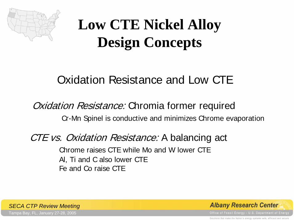
Low CTE Nickel Alloy Design Concepts
Oxidation Resistance and Low CTE
Oxidation Resistance: Chromia former requiredCr-Mn Spinel is conductive and minimizes Chrome evaporation
CTE vs. Oxidation Resistance: A balancing actChrome raises CTE while Mo and W lower CTEAl, Ti and C also lower CTEFe and Co raise CTE
SECA CTP Review MeetingTampa Bay, FL, January 27-28, 2005
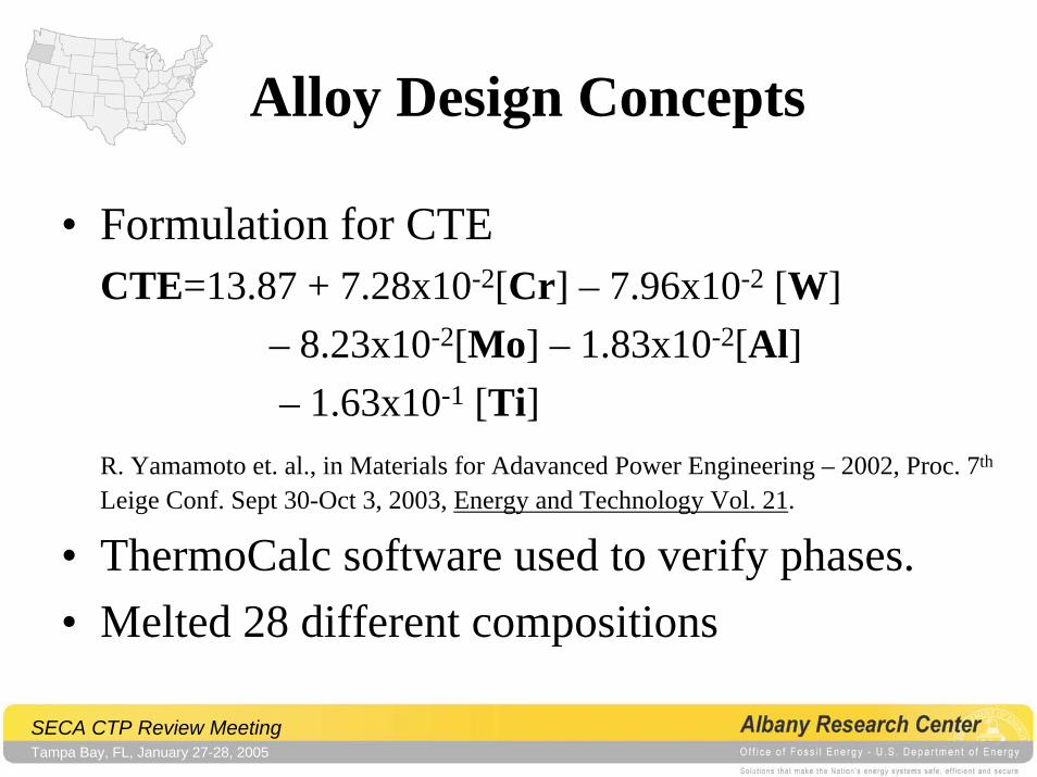
Alloy Design Concepts
• Formulation for CTECTE=13.87 + 7.28x10⁻²[Cr] – 7.96x10⁻² [W]
– 8.23x10⁻²[Mo] – 1.83x10⁻²[Al] – 1.63x10⁻¹ [Ti]
R. Yamamoto et. al., in Materials for Adavanced Power Engineering – 2002, Proc. 7th
Leige Conf. Sept 30-Oct 3, 2003, Energy and Technology Vol. 21.
• ThermoCalc software used to verify phases.• Melted 28 different compositions
SECA CTP Review MeetingTampa Bay, FL, January 27-28, 2005
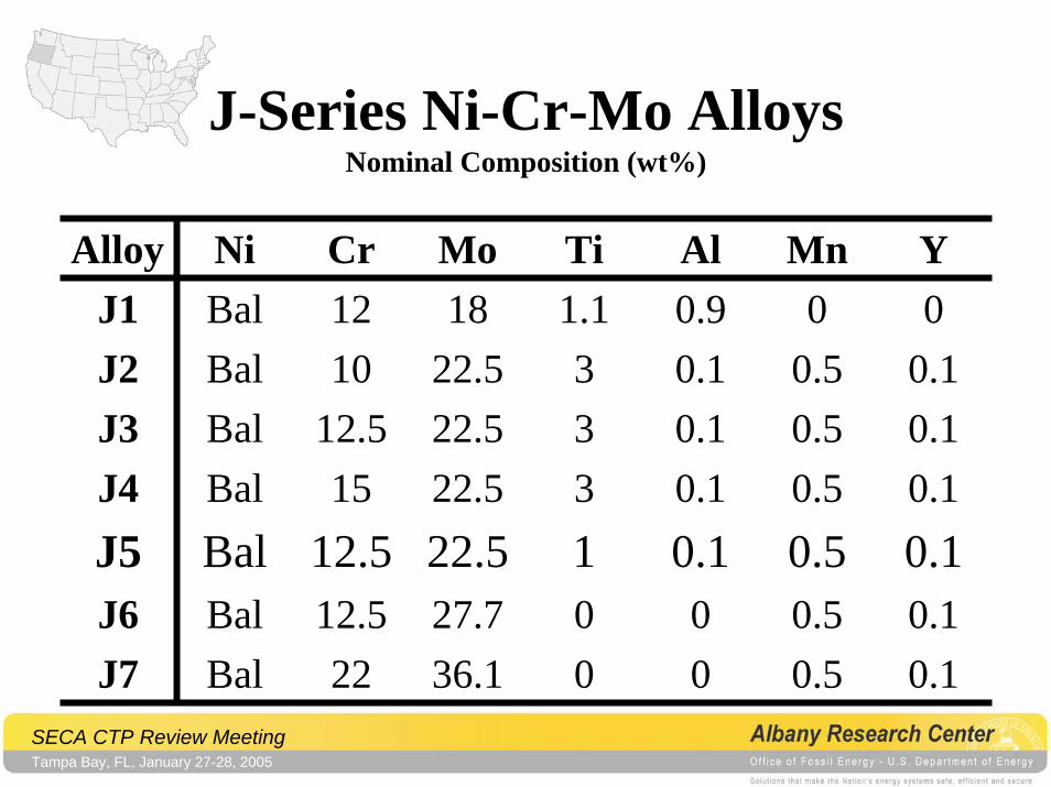
J-Series Ni-Cr-Mo AlloysNominal Composition (wt%)
Alloy Ni Cr Mo Ti Al Mn YJ1 Bal 12 18 1.1 0.9 0 0J2 Bal 10 22.5 3 0.1 0.5 0.1J3 Bal 12.5 22.5 3 0.1 0.5 0.1J4 Bal 15 22.5 3 0.1 0.5 0.1J5 Bal 12.5 22.5 1 0.1 0.5 0.1J6 Bal 12.5 27.7 0 0 0.5 0.1J7 Bal 22 36.1 0 0 0.5 0.1
SECA CTP Review MeetingTampa Bay, FL, January 27-28, 2005
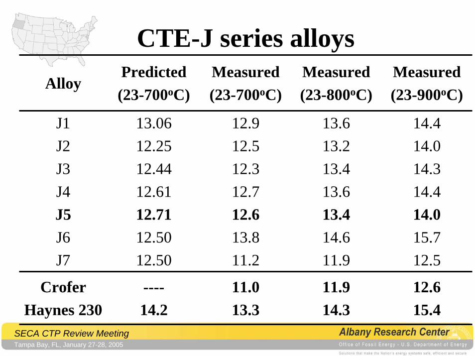
AlloyPredicted(23-700oC)
Measured(23-700oC)
Measured(23-800oC)
Measured(23-900oC)
J1J2J3J4J5J6J7
13.0612.2512.4412.6112.7112.5012.50
12.912.512.312.712.613.811.2
13.613.213.413.613.414.611.9
14.414.014.314.414.015.712.5
CroferHaynes 230
----14.2
11.013.3
11.914.3
12.615.4
CTE-J series alloys
SECA CTP Review MeetingTampa Bay, FL, January 27-28, 2005
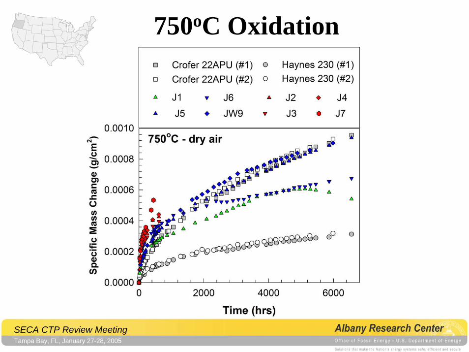
750oC Oxidation
SECA CTP Review MeetingTampa Bay, FL, January 27-28, 2005
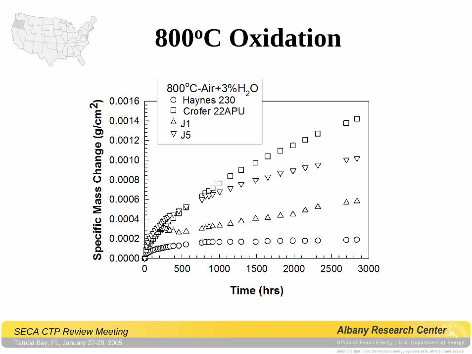
800oC Oxidation
SECA CTP Review MeetingTampa Bay, FL, January 27-28, 2005
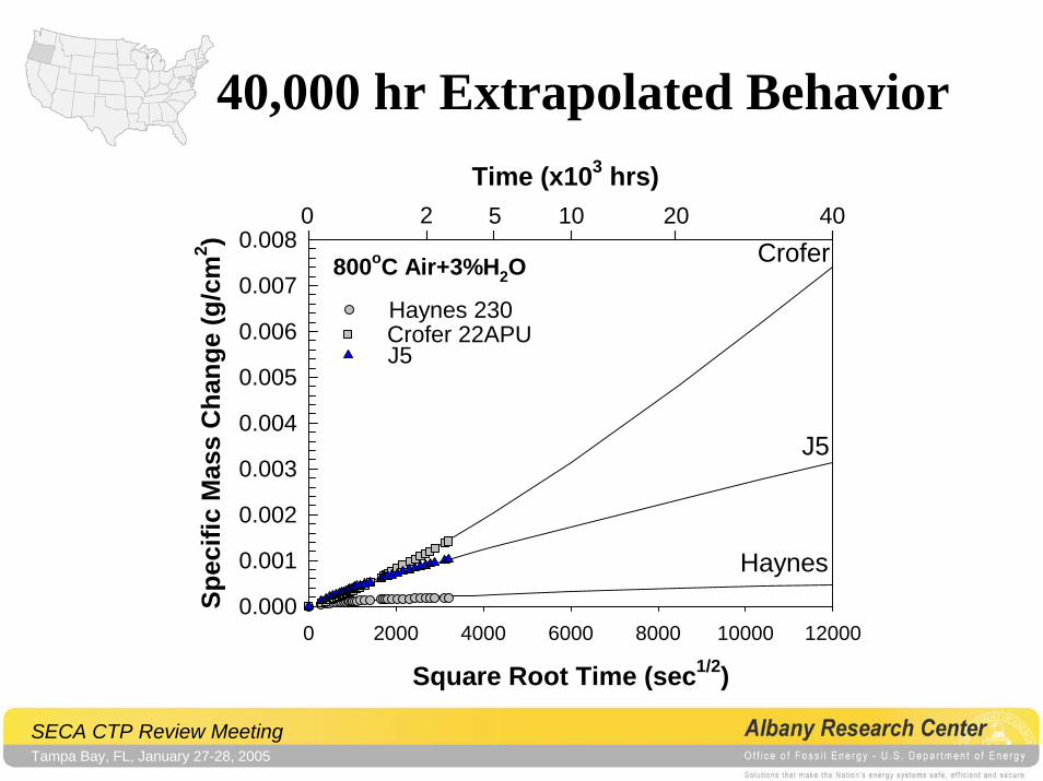
40,000 hr Extrapolated Behavior
Square Root Time (sec1/2)0 2000 4000 6000 8000 10000 12000
Spec
ific
Mas
s C
hang
e (g
/cm
2 )
0.000
0.001
0.002
0.003
0.004
0.005
0.006
0.007
0.008
Time (x103 hrs)2 5 10 20 400
Haynes
J5
Crofer
Haynes 230Crofer 22APUJ5
800oC Air+3%H2O
SECA CTP Review MeetingTampa Bay, FL, January 27-28, 2005
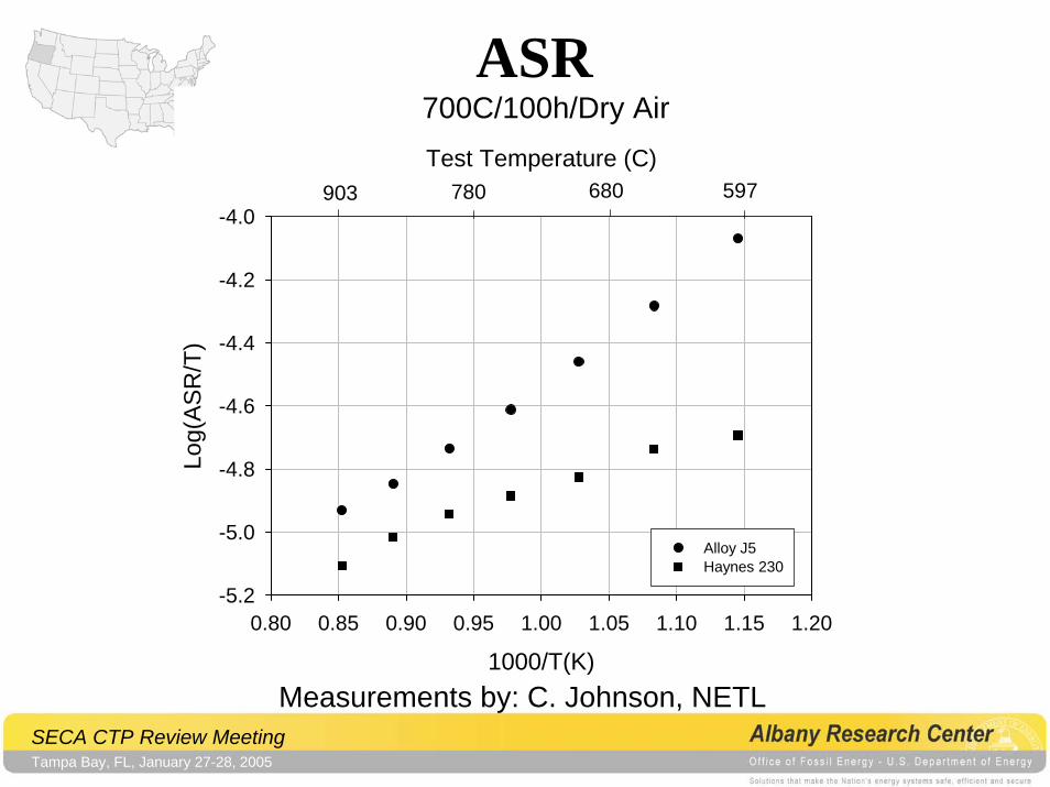
ASR700C/100h/Dry Air
1000/T(K)0.80 0.85 0.90 0.95 1.00 1.05 1.10 1.15 1.20
Log(
ASR
/T)
-5.2
-5.0
-4.8
-4.6
-4.4
-4.2
-4.0
Test Temperature (C)
Alloy J5 Haynes 230
780 680 597903
Measurements by: C. Johnson, NETL
SECA CTP Review MeetingTampa Bay, FL, January 27-28, 2005
Modifications for Improved Oxidation Resistance
• Ferritic Steels
• Nickel Alloys
SECA CTP Review MeetingTampa Bay, FL, January 27-28, 2005
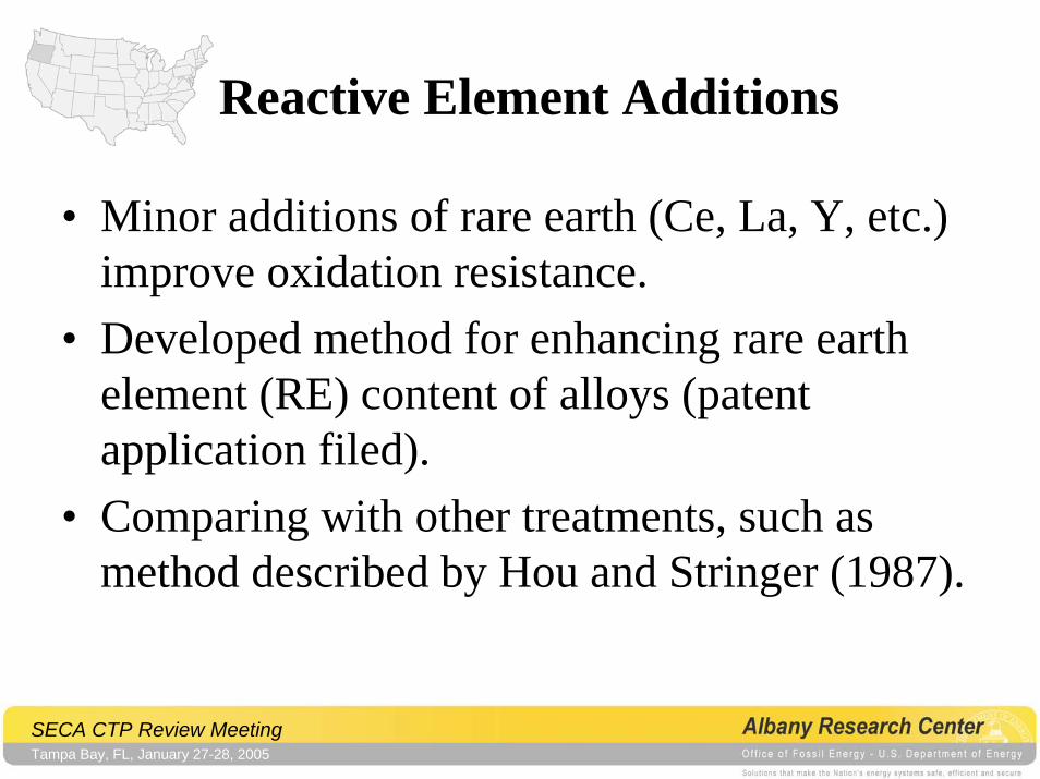
Reactive Element Additions
• Minor additions of rare earth (Ce, La, Y, etc.) improve oxidation resistance.
• Developed method for enhancing rare earth element (RE) content of alloys (patent application filed).
• Comparing with other treatments, such as method described by Hou and Stringer (1987).
SECA CTP Review MeetingTampa Bay, FL, January 27-28, 2005
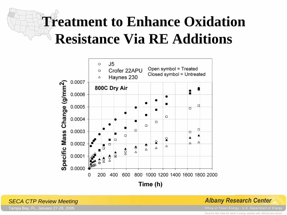
Treatment to Enhance Oxidation Resistance Via RE Additions
SECA CTP Review MeetingTampa Bay, FL, January 27-28, 2005
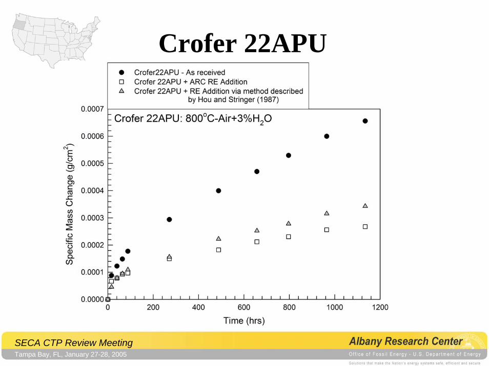
Crofer 22APU
SECA CTP Review MeetingTampa Bay, FL, January 27-28, 2005
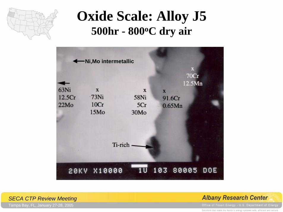
Oxide Scale: Alloy J5500hr - 800oC dry air
Ni,Mo intermetallic
SECA CTP Review MeetingTampa Bay, FL, January 27-28, 2005
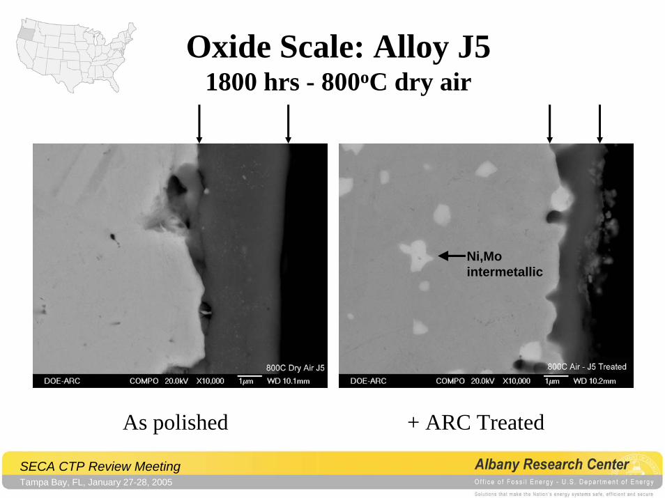
Oxide Scale: Alloy J5 1800 hrs - 800oC dry air
Ni,Mointermetallic
As polished + ARC Treated
SECA CTP Review MeetingTampa Bay, FL, January 27-28, 2005
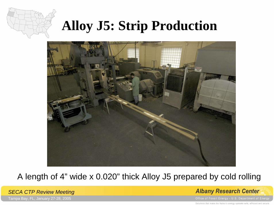
Alloy J5: Strip Production
A length of 4” wide x 0.020” thick Alloy J5 prepared by cold rolling
SECA CTP Review MeetingTampa Bay, FL, January 27-28, 2005
Alloy J5 Strip and Treated J5 Strip• PNNL (J. Stevenson and G. Yang)
– Sent for testing• GE (J. Guan, GE-Energy Systems and K. Browall, GE-GR&D)
– In process of delivering material• Requests for material from:
– Versa Power Systems (Canada)– Korean Advanced Institute of Science and Technology (Korea)– Ikerlan Technical Research Center (Spain)
• Will send sample of J5 to any SECA participant or US entity for evaluationContact: J. Dunning: [email protected]
(541) 967-5885
SECA CTP Review MeetingTampa Bay, FL, January 27-28, 2005
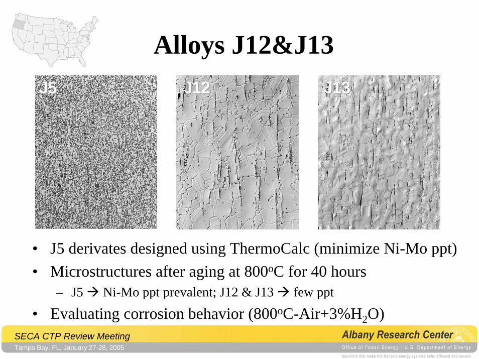
Alloys J12&J13J13J13J13J12J12J12J5J5J5
• J5 derivates designed using ThermoCalc (minimize Ni-Mo ppt)• Microstructures after aging at 800oC for 40 hours
– J5 Ni-Mo ppt prevalent; J12 & J13 few ppt
• Evaluating corrosion behavior (800oC-Air+3%H2O)
SECA CTP Review MeetingTampa Bay, FL, January 27-28, 2005
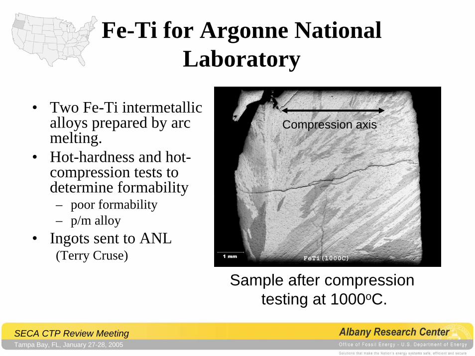
Fe-Ti for Argonne National Laboratory
Compression axis• Two Fe-Ti intermetallic
alloys prepared by arc melting.
• Hot-hardness and hot-compression tests to determine formability– poor formability– p/m alloy
• Ingots sent to ANL(Terry Cruse)
Sample after compression testing at 1000oC.
Materials Performance for Heat Exchangers & Other Balance of Plant
(BOP) Components for (SOFC)
SECA CTP Review MeetingTampa Bay, FL, January 27-28, 2005
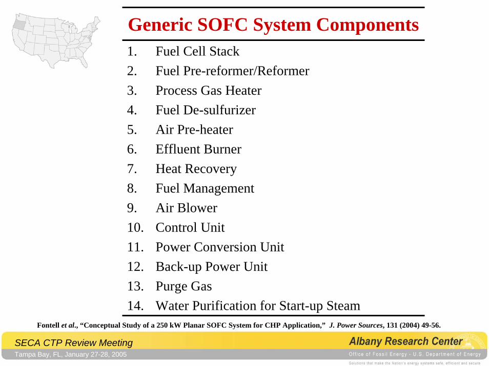
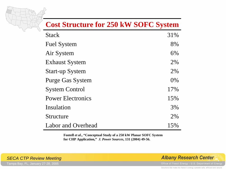
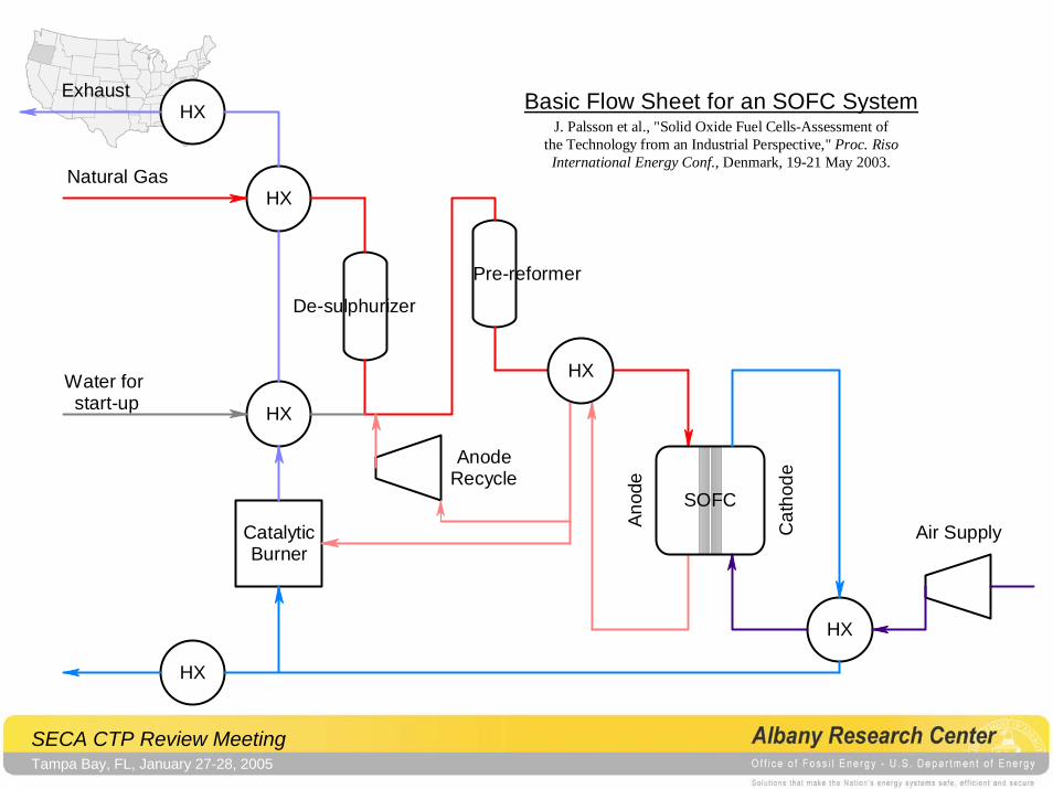
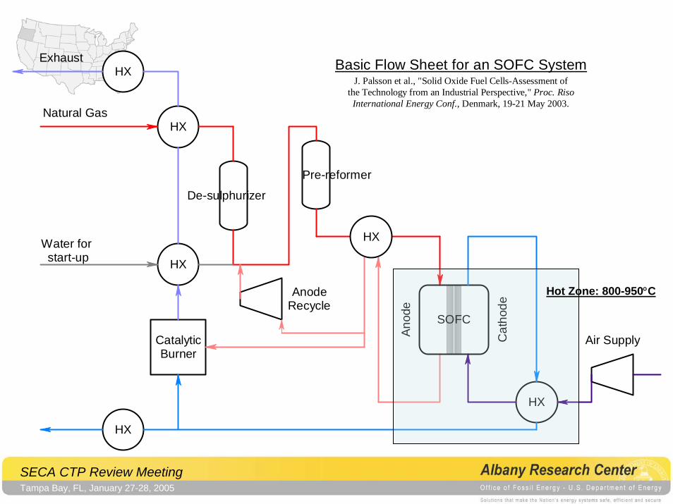
Generic SOFC System Components1. Fuel Cell Stack2. Fuel Pre-reformer/Reformer3. Process Gas Heater4. Fuel De-sulfurizer5. Air Pre-heater6. Effluent Burner7. Heat Recovery8. Fuel Management9. Air Blower10. Control Unit11. Power Conversion Unit12. Back-up Power Unit13. Purge Gas14. Water Purification for Start-up Steam
Fontell et al., “Conceptual Study of a 250 kW Planar SOFC System for CHP Application,” J. Power Sources, 131 (2004) 49-56.
SECA CTP Review MeetingTampa Bay, FL, January 27-28, 2005
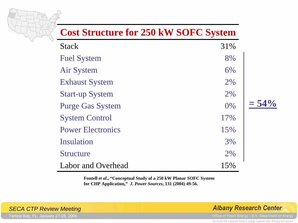
Cost Structure for 250 kW SOFC SystemStackFuel SystemAir SystemExhaust SystemStart-up SystemPurge Gas SystemSystem ControlPower ElectronicsInsulationStructureLabor and Overhead
31%8%6%2%2%0%
17%15%
3%2%
15%Fontell et al., “Conceptual Study of a 250 kW Planar SOFC Systemfor CHP Application,” J. Power Sources, 131 (2004) 49-56.
SECA CTP Review MeetingTampa Bay, FL, January 27-28, 2005
Cost Structure for 250 kW SOFC SystemStackFuel SystemAir SystemExhaust SystemStart-up SystemPurge Gas SystemSystem ControlPower ElectronicsInsulationStructureLabor and Overhead
31%8%6%2%2%0%
17%15%
3%2%
15%
= 54%
Fontell et al., “Conceptual Study of a 250 kW Planar SOFC Systemfor CHP Application,” J. Power Sources, 131 (2004) 49-56.
SECA CTP Review MeetingTampa Bay, FL, January 27-28, 2005
Exhaust
CatalyticBurner
Natural Gas
Water for start-up
Anod
e
Cat
hode
AnodeRecycle
HX
HX
HX
HX
Air Supply
SOFC
HX
Pre-reformer
De-sulphurizer
HX
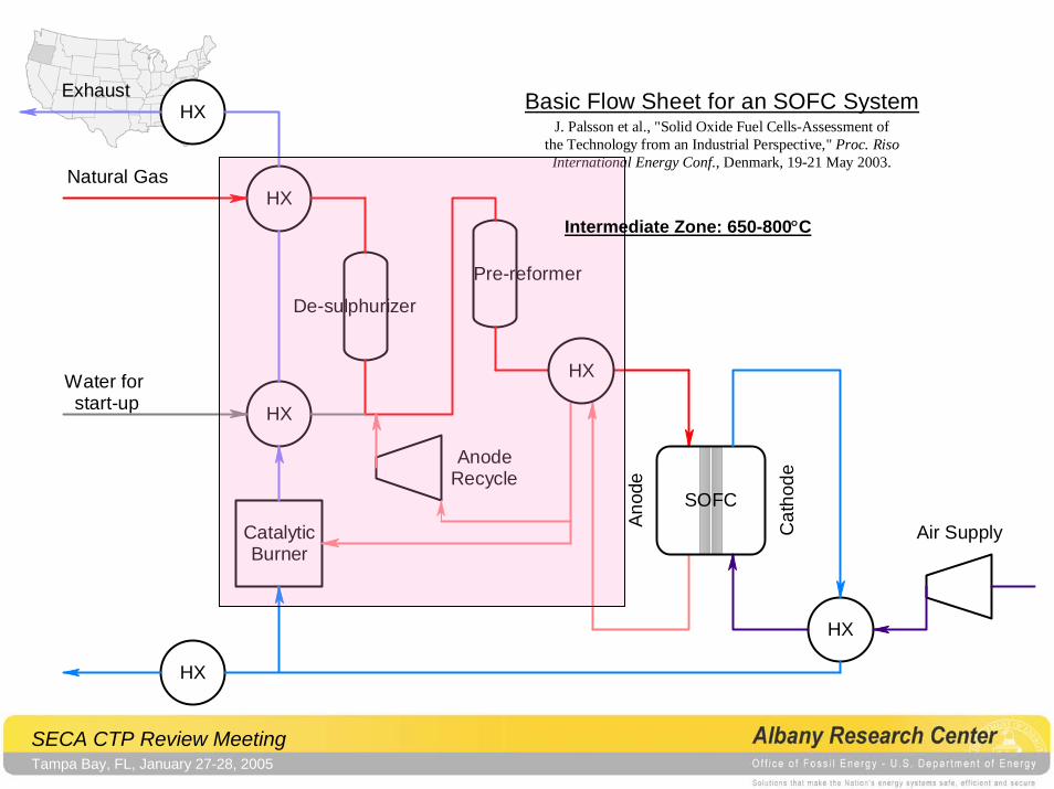
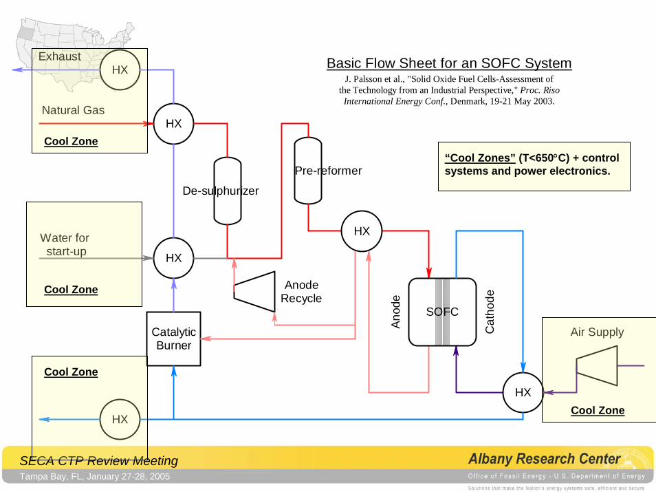
Basic Flow Sheet for an SOFC SystemJ. Palsson et al., "Solid Oxide Fuel Cells-Assessment of
the Technology from an Industrial Perspective," Proc. RisoInternational Energy Conf., Denmark, 19-21 May 2003.
SECA CTP Review MeetingTampa Bay, FL, January 27-28, 2005
Exhaust
CatalyticBurner
Natural Gas
Water for start-up
Anod
e
Cat
hode
AnodeRecycle
HX
HX
HX
HX
Air Supply
SOFC
HX
Pre-reformer
De-sulphurizer
HX
Basic Flow Sheet for an SOFC SystemJ. Palsson et al., "Solid Oxide Fuel Cells-Assessment of
the Technology from an Industrial Perspective," Proc. RisoInternational Energy Conf., Denmark, 19-21 May 2003.
Hot Zone: 800-950°C
SECA CTP Review MeetingTampa Bay, FL, January 27-28, 2005
Exhaust
CatalyticBurner
Natural Gas
Water for start-up
Anod
e
Cat
hode
AnodeRecycle
HX
HX
HX
HX
Air Supply
SOFC
HX
Pre-reformer
De-sulphurizer
HX
Basic Flow Sheet for an SOFC SystemJ. Palsson et al., "Solid Oxide Fuel Cells-Assessment of
the Technology from an Industrial Perspective," Proc. RisoInternational Energy Conf., Denmark, 19-21 May 2003.
Intermediate Zone: 650-800°C
SECA CTP Review MeetingTampa Bay, FL, January 27-28, 2005
Exhaust
CatalyticBurner
Natural Gas
Water for start-up
Anod
e
Cat
hode
AnodeRecycle
HX
HX
HX
HX
Air Supply
SOFC
HX
Pre-reformer
De-sulphurizer
HX
Basic Flow Sheet for an SOFC SystemJ. Palsson et al., "Solid Oxide Fuel Cells-Assessment of
the Technology from an Industrial Perspective," Proc. RisoInternational Energy Conf., Denmark, 19-21 May 2003.
Cool Zone
Cool Zone
Cool Zone
“Cool Zones” (T<650°C) + controlsystems and power electronics.
Cool Zone
SECA CTP Review MeetingTampa Bay, FL, January 27-28, 2005
BOP Component Design and Testing Strategy
1. Define the component requirements.
2. Identify candidate materials.
3. Evaluate materials in depth.
4. Specify and select materials.
5. Establish a strategy for evaluating generic candidate BOP components.
SECA CTP Review MeetingTampa Bay, FL, January 27-28, 2005
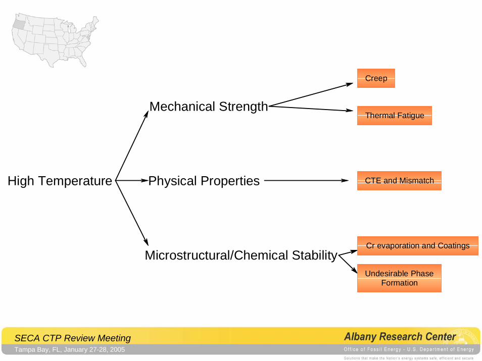
High Temperature
Microstructural/Chemical Stability
Physical Properties
Mechanical Strength
Undesirable PhaseFormation
Cr evaporation and Coatings
CTE and Mismatch
Thermal Fatigue
Creep
SECA CTP Review MeetingTampa Bay, FL, January 27-28, 2005
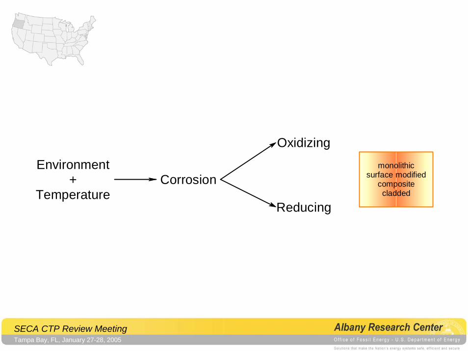
Environment+
TemperatureCorrosion
Reducing
Oxidizingmonolithic
surface modifiedcompositecladded
SECA CTP Review MeetingTampa Bay, FL, January 27-28, 2005
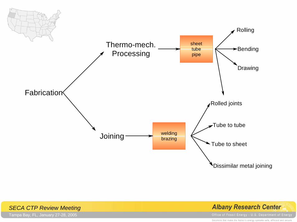
Fabrication
Joining
Thermo-mech.Processing
weldingbrazing
sheettubepipe
Bending
Drawing
Rolling
Tube to tube
Rolled joints
Tube to sheet
Dissimilar metal joining
SECA CTP Review MeetingTampa Bay, FL, January 27-28, 2005
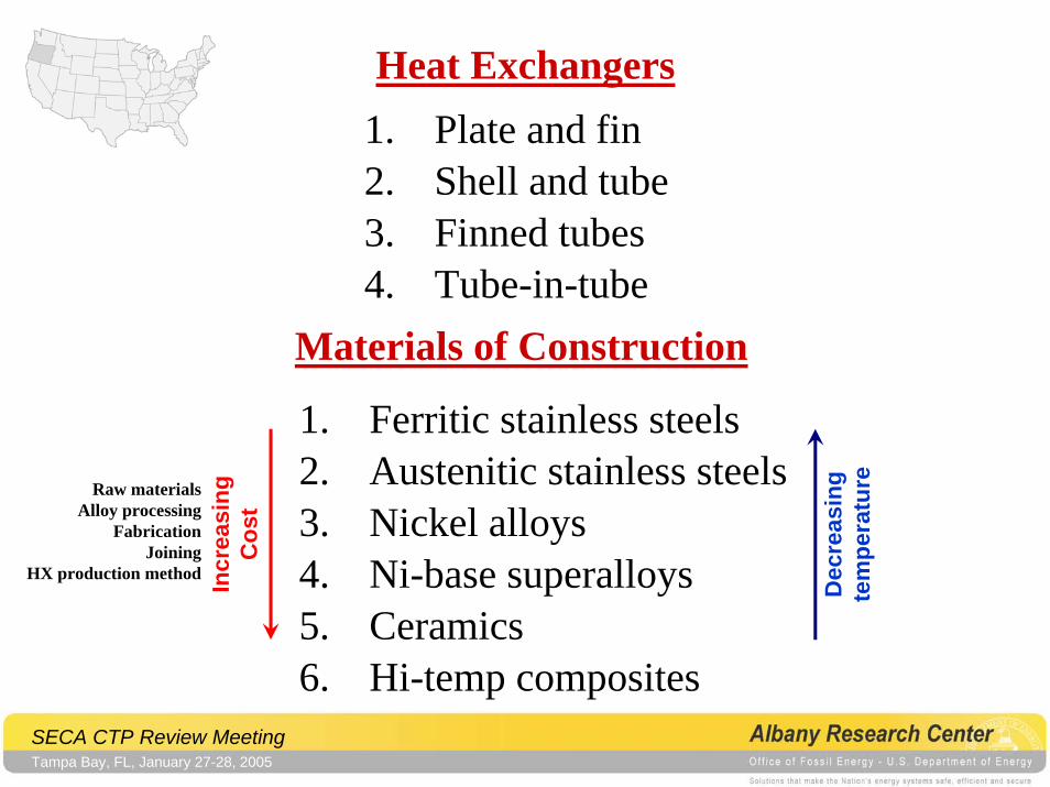
Heat Exchangers1. Plate and fin2. Shell and tube3. Finned tubes4. Tube-in-tube
Materials of Construction
1. Ferritic stainless steels2. Austenitic stainless steels3. Nickel alloys4. Ni-base superalloys5. Ceramics6. Hi-temp composites
Dec
reas
ing
tem
pera
ture
Incr
easi
ngC
ost
Raw materialsAlloy processing
FabricationJoining
HX production method
SECA CTP Review MeetingTampa Bay, FL, January 27-28, 2005
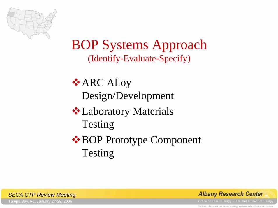
BOP Systems Approach(Identify-Evaluate-Specify)
ARC Alloy Design/DevelopmentLaboratory Materials TestingBOP Prototype Component Testing
SECA CTP Review MeetingTampa Bay, FL, January 27-28, 2005
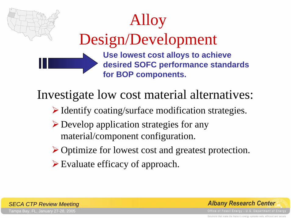
Alloy Design/Development
Use lowest cost alloys to achievedesired SOFC performance standardsfor BOP components.
Investigate low cost material alternatives:Identify coating/surface modification strategies.Develop application strategies for any material/component configuration.Optimize for lowest cost and greatest protection.Evaluate efficacy of approach.
SECA CTP Review MeetingTampa Bay, FL, January 27-28, 2005
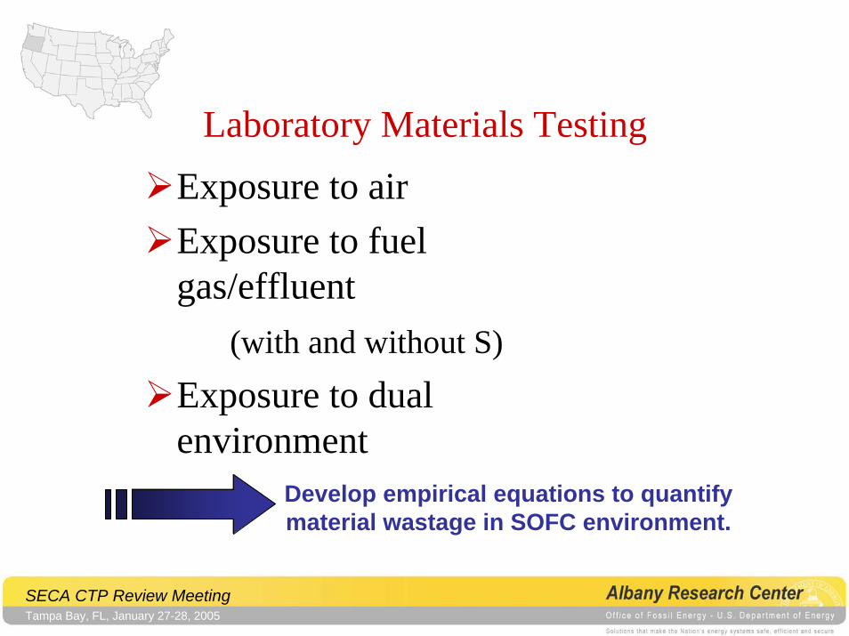
Laboratory Materials TestingExposure to airExposure to fuel gas/effluent
(with and without S)
Exposure to dual environment
Develop empirical equations to quantifymaterial wastage in SOFC environment.
SECA CTP Review MeetingTampa Bay, FL, January 27-28, 2005
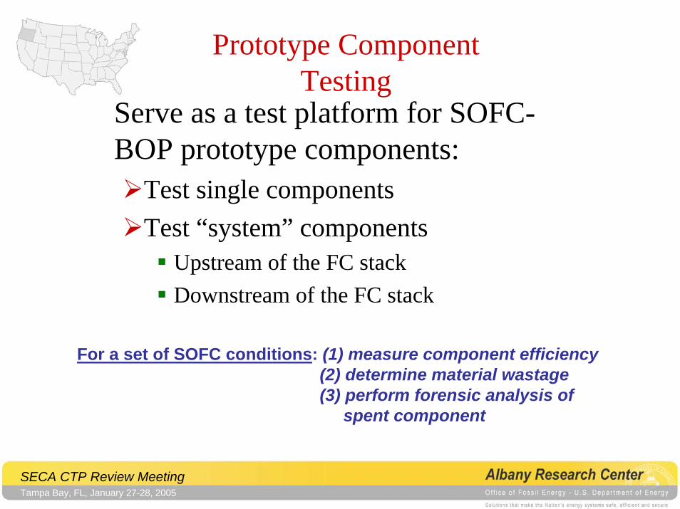
Prototype Component Testing
Serve as a test platform for SOFC-BOP prototype components:
Test single componentsTest “system” components
Upstream of the FC stackDownstream of the FC stack
For a set of SOFC conditions: (1) measure component efficiency(2) determine material wastage(3) perform forensic analysis of
spent component
SECA CTP Review MeetingTampa Bay, FL, January 27-28, 2005
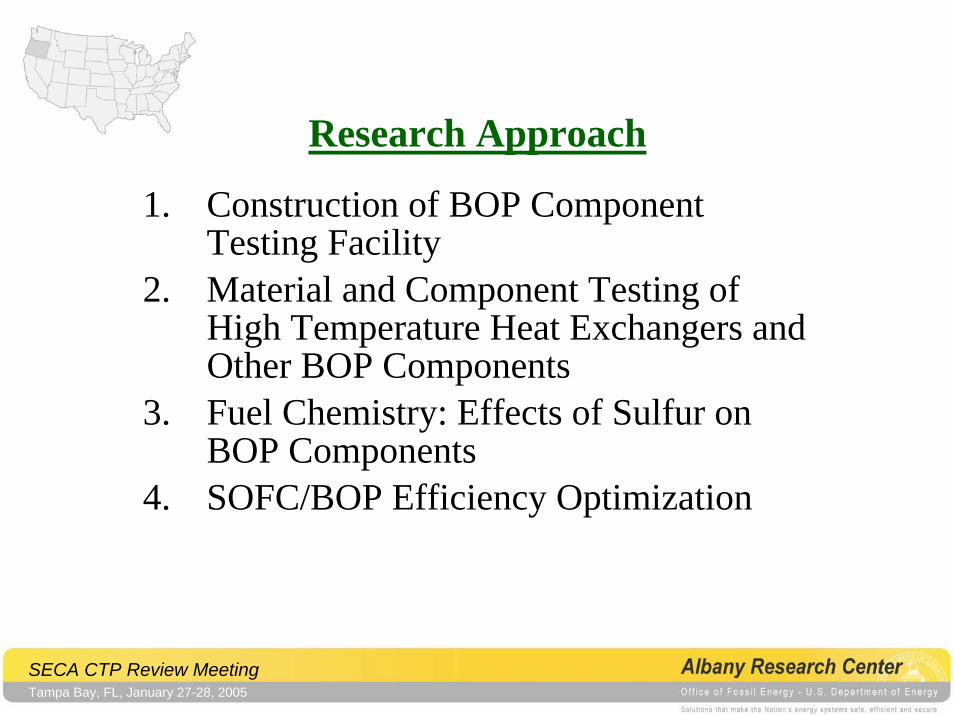
Research Approach
1. Construction of BOP Component Testing Facility
2. Material and Component Testing of High Temperature Heat Exchangers and Other BOP Components
3. Fuel Chemistry: Effects of Sulfur on BOP Components
4. SOFC/BOP Efficiency Optimization
SECA CTP Review MeetingTampa Bay, FL, January 27-28, 2005
Construction of BOP Testing Facility
ApproachSimulated combustion environment using a “furnace/hotbox” with feed through connections for air and fuel/effluent gases.
SECA CTP Review MeetingTampa Bay, FL, January 27-28, 2005
Material and Component Testing of High Temperature Heat Exchanger
• Mechanical and Physical Property Behavior of BOP Candidate Materials
• Prototype BOP Component Testing• Microscopic Investigations• Characterization of Scales
SECA CTP Review MeetingTampa Bay, FL, January 27-28, 2005
Prototype BOP Component Testing• Test facility must be flexible enough to use:
different fuel chemistriesdifferent operating temperaturesdifferent operating pressures (but not pressurized)
• Must be modular in design to facilitate the easy insertion and removal of BOP components
• Allow easy post mortem analysis of BOP components
• Allow evaluation of operating efficiency of the “system” for both the SOFC and the BOP components
SECA CTP Review MeetingTampa Bay, FL, January 27-28, 2005
General Summary
• Identify, evaluate (test as needed) and specify materials for use as BOP components in SOFC applications. Explore coating/surface modification strategies to extend operational range.
• Design and construct a BOP component and BOP component system test facility.
SECA CTP Review MeetingTampa Bay, FL, January 27-28, 2005
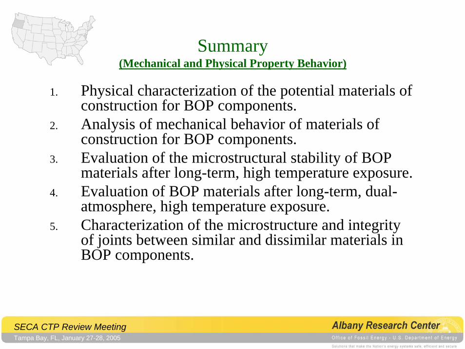
Summary(Mechanical and Physical Property Behavior)
1. Physical characterization of the potential materials of construction for BOP components.
2. Analysis of mechanical behavior of materials of construction for BOP components.
3. Evaluation of the microstructural stability of BOP materials after long-term, high temperature exposure.
4. Evaluation of BOP materials after long-term, dual-atmosphere, high temperature exposure.
5. Characterization of the microstructure and integrity of joints between similar and dissimilar materials in BOP components.
SECA CTP Review MeetingTampa Bay, FL, January 27-28, 2005
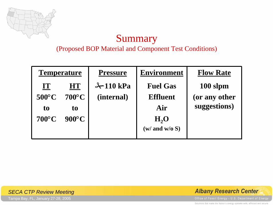
Summary(Proposed BOP Material and Component Test Conditions)
Temperature Pressure Environment Flow Rate
IT500°C
to700°C
HT700°C
to900°C
110 kPa(internal)
Fuel GasEffluent
AirH2O
(w/ and w/o S)
100 slpm(or any other suggestions)
SECA CTP Review MeetingTampa Bay, FL, January 27-28, 2005
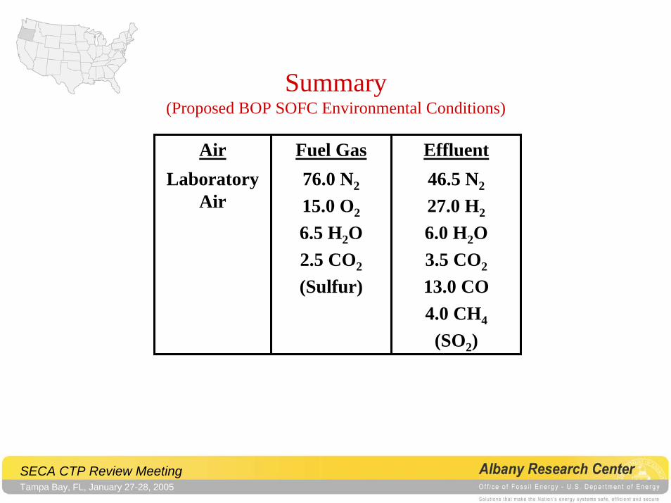
Summary(Proposed BOP SOFC Environmental Conditions)
Air Fuel Gas EffluentLaboratory
Air76.0 N2
15.0 O2
6.5 H2O2.5 CO2
(Sulfur)
46.5 N2
27.0 H2
6.0 H2O3.5 CO2
13.0 CO4.0 CH4
(SO2)