Embed Size (px)
Citation preview

user manual
Sollight®
Metallic coated steelUser manual
Flat Carbon Europe


3
User manualMetallic coated steel
1 Introduction 5
2 Products 9
3 Production process 15
4 Durability and protection 19
5 Recommendations for transport, storage and primary transformation 25
6 Forming 29
7 Joining 39
8 Painting 49
9 Conclusion 55


5
1 Introduction
1.1 Metallic coated steel in our daily life 6
1.2 Definition 6
1.3 Environment 6

6 User manual – Metallic coated steel – ArcelorMittal
1.1 Metallic coated steel in our daily life
The wide range of metallic coated steel is an integral part of our daily life: it is used to protect, shelter, package and transport and at the same time meets the demand for a solid, durable and aesthetically pleasing material. Continuous metallic coated steel has experienced a remarkable growth and continues to be used in increasingly varied new fields. This is due to its outstanding economic, technological and environmental advantages.
In building and construction, metallic coated sheet has been used in the form of profiled parts for roofing, cladding and as cold formed sections for many years, but it is also used for applications such as doors, stairs, ceilings etc.
These products have a very wide range of applications in general industry, e.g. furniture, air conditioning, tanks, thermal shields etc.
The domestic appliance sector is also a big user of metallic coated steel. There is even a trend today towards building domestic appliances entirely from metallic coated steel, both white goods (refrigerators, washing machines, ovens etc) and brown goods (teletronics, video, hifi etc).
1.2 Definition
Metallic coated steel can be defined as a steel substrate coated with a layer of zinc, a zinc/aluminium alloy, a zinc/silicon alloy or pure aluminium.
• The electrogalvanising process, in which metal is deposited electrolytically on the cold steel strip.
• Coating under vacuum, such as PVD (Physical Vapour Deposition), CVD (Chemical Vapour Deposition) etc. This manual does not deal with these processes.
Process Hot dip coating Electrodeposition
Products Galvanised (Z)pure zinc coating
Electrogalvanisedpure zinc coating
Galfan (ZA)zinc/aluminium coating
Magnelis® (ZM) zinc/aluminium/magnesium coating
Aluzinc® (AZ)aluminium/zinc/silicon coating
Alusi® (AS)aluminium/silicon coating
Alupur® (AL)pure aluminium coating
1.3 Environment
Metallic coated steel is certainly the product best able to meet present and future environmental regulations. ArcelorMittal has opted for a proactive approach to the evolution of these regulations by building respect for the environment into the life cycle of its metallic coated steel products. This strategy is pursued at all stages of the product’s life cycle:
• Design: When designing new products or production processes, research teams take their possible environmental impact into account from the earliest stages of the project.
• Production: Metallic coated steel is produced on industrial lines designed to meet the most stringent environmental regulations concerning surface treatments and the absence of harmful substances in the metallic coating composition.
• Usage: The use of metallic coated steel entails no danger to the consumer or the environment in the various sectors in which it is used, namely the construction business, domestic appliances and industry.
• Recycling: At the end of its life cycle, metallic coated steel is recycled just like any other steel product.
1 Introduction
These products are manufactured on continuous production lines. There are several different coating processes:
• The hot dip coating process, whereby the steel strip is immersed in a bath of molten metal. The composition of the molten metal (zinc, zinc/aluminium, aluminium/silicon or pure aluminium) determines the nature of the metal coating.
metallic coating
steel
metallic coating

7User manual – Metallic coated steel – ArcelorMittal
Important progress has been made on the following:
Regarding the removal of harmful substances from our products, ArcelorMittal’s first target was the removal of lead and hexavalent chromium from our metallic coated steels. Hot dip galvanised products now coming off our production lines are lead-free and protected by chromatefree passivation.
Regarding the processes used, progress has been made on improved efficiency of energy use on industrial production lines (furnace optimisation, heat recovery systems, gas recycling) and reduction of water consumption (zero waste, efficient filtration systems for baths with a closed loop process).
Improved efficiency in metallic coating material use is another target, and this has been achieved by measurably reducing coating thickness and “scattering” (improved consistency). The reduction of “excess coating” also improves performance in other areas, including weldability and achieving the exact degree of corrosion resistance required.
Some environmentally friendly temporary protection so-lutions such as dry lubricants are also beneficial innovations improving both the formability of the steel and cleanliness in the workshops. In fact, certain pretreatments can help customers to move towards more HSE (Health, Safety & Environment) friendly processes and products.


9
2 Products
2.1 Introduction 10
2.2 Quality or grade of the steel 10
2.3 Types of coating 10 2.3.1 Electrogalvanised steel 10 2.3.2 Hot dip galvanised steel 10 2.3.3 Steel with zinc-aluminium coating galfan 11 2.3.4 Steel with zinc-aluminium-magnesium coating Magnelis® 11 2.3.5 Steel with aluminium-zinc coating Aluzinc® 12 2.3.6 Steel with aluminium-silicon coating Alusi® 12 2.3.7 Steel with aluminium coating Alupur® 12
2.4 Mass or thickness of the coating 13
2.5 Surface aspect 13
2.6 Surface quality 13
2.7 Surface treatment 13
2.8 Tolerances on dimensions and shape 14

10 User manual – Metallic coated steel – ArcelorMittal
2 Products
2.1 Introduction
The wide range of metallic coated steel products available today meets the requirements of all sectors. Different parameters govern the choice of the material:• Quality or grade of the steel• Types of coating• Mass or thickness of the coating• Surface aspect• Surface quality• Surface treatment• Tolerances on dimensions and shape
2.2 Quality or grade of the steel
ArcelorMittal offers three main groups of steel types as a substrate for metallic coating:• Steel for bending and deep drawing applications• Structural steel• High Strength Low Alloy steel
2.3 Types of coating
ArcelorMittal offers six types of zincbased or alloyed metallic coatings:
2.3.1 Electrogalvanised steel
Electrogalvanised steel is a flat carbon product coated with a pure zinc layer on one or both sides. The electrogalvanising process allows a very high degree of chemical purity to be obtained, together with excellent control of coating thickness in all directions. Due to the sacrificial action of zinc, corrosion protection continues even if the coating is damaged; moreover the homogeneity of this coating has a beneficial effect on corrosion resistance. The surface quality of electrogalvanised steel makes it ideal for the manufacture of visible components. Consequently, electrogalvanised products are appreciated for their outstanding appearance after painting.
Electrolytically zinccoated steel is obtained by electroplating, more commonly known as electrogalvanising. With this process, it is possible to apply a very pure coating with an extremely regular thickness. The coating consists of tiny juxtaposed crystals which give excellent coverage. Consequently, electrogalvanised steel has good weldability.
Electrogalvanised steel is generally only available with a thin coating, which means that this product has only limited corrosion resistance in the bare state (electrogalvanised steel is therefore not suitable for outdoor applications).
Typical applications for electrogalvanised steel are indoor construction applications, which require an excellent surface finish (ceilings, partitions etc), electrical and electronic appliances (teletronic casings), metal furniture etc. These applications need a coating thickness of some microns to offer good corrosion protection.
2.3.2 Hot dip galvanised steel
Hot dip galvanised steel consists of a steel substrate with a zinc coating which is applied in a continuous hot dip process using a bath of molten zinc. Hot dip galvanised products offer very good corrosion resistance due to the cathodic and barrier protection provided by the zinc coating, combined with good forming properties. The coating has a bright metallic appearance.
The galvanised coating is composed of three layers:• A very thin intermetallic layer (Fe2Al5) at the steelcoating
interface (too thin to be seen by optical microscopy, thickness of more or less 100 nm)
• The zinc coating layer itself• An oxidised, aluminium enriched top layer
(extremely thin layer of about 50 nm)
10 µm

11User manual – Metallic coated steel – ArcelorMittal
10 µm
zinc layer oxidised top surface layer
steel
Fe2Al5 layer
Micrographic cross-section of a galvanised coating, illustrating its structure
Hot dip galvanised steel is characterised by a very wide range of coating thicknesses, steel substrates and dimensions. This creates a large field of applications, both indoor and outdoor: structural profiles for building, panels and structures for domestic appliances, metal furniture etc. Steel substrates available with this coating range from soft forming grades and structural steels to high strength steels for weightsaving applications.
2.3.3 Steel with zinc-aluminium coating galfan
This hot dip coating is composed of approximately 95% zinc and 5% aluminium. Zinc dendrites are surrounded by a two phase eutectic. At the interface with the steel, there is a very thin FeAl3 intermetallic layer (< 100 nm). This provides excellent flexibility and makes it suitable for the production of particularly difficult workpieces. General corrosion resistance is outstanding: on ave rage, it is double that of standard galvanised products.
20 µm
lamellar Zn-Al eutectic structure
steel
FeAl3 intermetallic layer
Micrographic cross-section of galfan coating, illustrating its structure
This excellent corrosion resistance is ideal for applications such as doors and garages, HVACequipment, washing machines, swimming pools etc.
2.3.4 Steel with zinc-aluminium-magnesium coating Magnelis®
Magnelis® is a steel substrate coated with a zinc-aluminium-magnesium alloy on both sides and offering extraordinary corrosion resistance. The alloy coating is composed of 93.5% zinc, 3.5% aluminium and 3.0% magnesium and is applied in a hotdip process. It has been developed in order to give improved corrosion resistance in aggressive environments, with greatly improved corrosion behaviour on cut edges.
Micrographic cross-section of Magnelis® coating, illustrating its structure
The 3.0% magnesium content in the coating alloy is crucial, as it creates a stable and durable layer across the entire surface, protecting the coating from corrosion and thus contributing to enhancing overall corrosion resistance of the system. Protection of cut edges is ensured by a thin zincbased film containing magnesium, which is formed in interaction with the atmosphere. The nature of this protective film depends on the environment; it prevents corrosive reactions and thus reinforces the cathodic protection of the edges – a phenomenon that is also observed in other metallic coated sheets.
Magnelis® has a corrosion resistance up to ten times higher than standard hotdip galvanised steel. It is typically applied in the harshest environments and where longterm protection is needed: for buildings at the seaside, outdoor civil construction and industrial installations. Thanks to its excellent corrosion protection, Magnelis® is a costeffective alternative to stainless steel, aluminium and batchgalvanised material. The improved corrosion protection of Magnelis® also enables standard HDG with a high coating thickness to be replaced by Magnelis® with a reduced coating thickness.

12 User manual – Metallic coated steel – ArcelorMittal
2.3.5 Steel with aluminium-zinc coating Aluzinc®
Aluzinc® is a steel substrate coated with an aluminium-zinc alloy on both sides by means of a hot dip process. Its composition is: aluminium (55%), zinc (43.4%) and silicon (1.6%).
Basically, Aluzinc® is a two phase coating: aluminium rich dendrites (80% vol) and zinc rich interdendritic zones (20% vol) containing silicon rich particles. At the interface with the steel, there is an intermetallic layer AlZnFeSi (1 to 2 µm thick).
20 µm
Zn rich phase
steel
AlZnFeSi
Al rich phase
Micrographic cross-section of Aluzinc® coating, illustrating its structure
Aluzinc® combines the advantages of the two major components of the coating: the barrier effect of aluminium and the sacrificial protection of zinc, resulting in excellent resistance to surface corrosion. The characteristic silver metallic colour with small spangles gives Aluzinc® a very attractive appearance. This is preserved over time without dulling, thanks to a thin, transparent layer of aluminium oxides formed on the surface. Aluminiumzinc coated steel offers even more advantages: good corrosion resistance at high temperatures, good abrasion resistance due to its surface hardness and excellent thermal and light reflectivity.
This excellent corrosion resistance and its other outstanding properties make Aluzinc® a very popular product for outdoor construction applications such as roofing, silo cladding and profiling. Other applications are found in the domestic appliances sector and general industry. The electrical resistance of its surface makes it highly suitable for the manufacture of switchboxes.
2 Products
2.3.6 Steel with aluminium-silicon coating Alusi®
Alusi® is a steel substrate, hotdip coated on both sides with an aluminium-silicon alloy in a continuous process. The coating is composed of 90% aluminium and 10% silicon. The composition of the coating gives Alusi® particularly high resistance to oxidation at high temperatures. The presence of silicon allows it to be used at temperatures as high as 650°C and up to 800°C (depending on the grade). In contact with oxygen, a passivating layer of aluminium oxide forms instantaneously. As this passivation protection is renewed when the coating is damaged (by scratches for example), it provides excellent resistance to chemical corrosion.
needles Al-Fe-Si
matrix Al-Si10 µm
FeAl3 + Fe2Al5
Micrographic cross-section of Alusi® coating, illustrating its structure
Thanks to its excellent resistance to high temperatures, Alusi® is ideally suited for use as a thermal screen. Some grades can be enamelled.
Typical uses are: exhaust systems, thermal shields, heating equipment, boilers, frying pans, barbecues, baking trays etc. Under certain conditions, Alusi® is suitable for food contact.
2.3.7 Steel with aluminium coating Alupur®
Alupur® is a steel substrate coated on both sides with pure aluminium without any addition of silicon or other alloying elements. Consequently a considerable aluminiumiron intermetallic layer is formed at the interface of the two metals.
20 µm
FeAl3 + Fe2Al5
Al
steel
Micrographic cross-section of Alupur® coating, illustrating its structure

13User manual – Metallic coated steel – ArcelorMittal
Alupur® shows very good corrosion resistance in all environments (urban, industrial and marine), and also in the presence of extremely aggressive combustion products at a high temperature. Alupur® coated steels offer good thermal and light reflectivity, and the coating can be used at temperatures as high as 650°C. Weathering may alter the appearance of Alupur®.
The Alupur® range is used in many applications both indoors and outdoors. The most common ones are: culverts, chimney ducts, housing for heating, ventilation and air conditioning equipment, pipe cladding, tanks etc. Its resistance to high temperatures combined with good resistance to aggressive combustion products makes Alupur® an excellent solution for applications in power generation plants and the petrochemical industry.
2.4 Mass or thickness of the coating
For continuous hotdip metallic coated steel, the nominal mass of the metallic coating is represented by the total minimum quantity of coating deposited on the two sides, expressed in g/m2.
The electrogalvanising process offers the most accurate control of coating thickness, whereby the amount of zinc on each side of the steel can be expressed in µm per side. The process also allows differential coatings with a thicker zinc layer on one side of the sheet.
Obviously, the amount of metallic coating on the steel is a function of the corrosion protection or durability required. Light coatings are used where corrosive conditions are not severe, such as for indoor applications. Heavy coatings, e.g. zinc coating weights of 350 up to 900 g/m2, may be required for outdoor use in severely corrosive environments.
2.5 Surface aspect
The formation of zinc crystals during solidification of the hot dip galvanised coating generates the familiar flowerlike spangle effect on the surface of the sheet for a suitable bath composition. This effect can be controlled by adding certain products to the galvanising bath. ArcelorMittal offers an environmentally friendly, leadfree metallic coating.
Spangle may be reduced or completely suppressed.
2.6 Surface quality
According to the acceptability of small irregularities in the surface aspect, the products are further defined by the quality of the surface finish:A: Standard surface qualityB: Improved surface qualityC: Superior surface quality B and C are normally obtained by passing the galvanised steel through a skinpass in a temper mill. This may influence the gloss of the coating surface.
2.7 Surface treatment
Metallic coated steel may be given a subsequent surface treatment to further enhance the performance of the metallic coating:
Chemical passivation (C): E-Passivation®
Chemical passivation systems can significantly increase temporary corrosion protection (prevention of surface corrosion during transport and storage).ArcelorMittal offers environmentally friendly chromatefree passivation products on all metallic coated steel (ZE, Z, ZA, ZM, AZ, AS and AL). These new chromatefree formulations have identical properties to conventional chromate (VI) passivation products.
E-Passivation®
metallic coating
steel
Oil (O)
Rustinhibiting oils can be applied as a lubricant and temporarily corrosion protection. Oiling can be combined with a chemical passivation treatment.
Phosphating (P)
Phosphating can be combined with chemical passivation and/or oiling.

14 User manual – Metallic coated steel – ArcelorMittal
Thin organic coating (S)
In addition to these surface treatments, ArcelorMittal can also supply metallic coated steel with a thin organic coating Easyfilm®.Easyfilm® is a transparent thin organic coating (TOC) composed of thermoplastic polymers applied to one of our metallic coated steel products.
The essential roles of Easyfilm® are: • To ensure corrosion protection during storage and
transport • To obtain resistance to fingerprinting • To facilitate forming (possible without the use
of lubricating oils) • To allow directon painting (without pretreatment)
This thin organic coating has virtually no effect on the appearance of the underlying metallic coating. The usual coating weight for a thin organic coating is about 1 g/m2 (approx. 1 µm thickness) on each side.
Easyfilm® E is an environmentally friendly thin organic coating (chromatefree, free of hazardous substances such as heavy metals) complying with the most recent European directives banning hazardous compounds.
• Chromatefree passivation systems are used• One or several organic or organometallic, nonchromium
based corrosion inhibitors are added• New functionalised resins are used to enhance polymer
polymer adhesion during paint curing
Easyfilm®
metallic coating
steel
2.8 Tolerances on dimensions and shape
Unless different instructions have been given with the order, the metallic coated steel coils are delivered within the tolerances specified in the most recent European standards with regard to thickness, flatness and width. Special tolerances on dimensions and flatness are also available.
2 Products

15
3 Production process
3.1 The electrogalvanising process 16 3.1.1 Entry section 16 3.1.2 Central section 16 3.1.3 Exit section 17
3.2 Hot dip coating 17 3.2.1 Entry section 17 3.2.2 Central section 17 3.2.3 Exit section 18

16 User manual – Metallic coated steel – ArcelorMittal
3 Production process
Electrogalvanised coatings are applied continuously to steel strip by passing the substrate through an electroplating bath.
The layout of a continuous electrogalvanising line consists of three main sections: entry, central section (surface preparation and coating) and exit.
In order to maintain the same processing speed in the surface preparation section and the coating section (which is an important parameter for the quality of the zinc coating layer), two accumulators separate the three sections. These are used as buffers when the entry or exit section is stopped to join or cut the coil.
3.1.1 Entry section
Steel coils are mounted on a decoiler. Since the process is continuous, the head of the incoming coil is welded to the tail of the coil being processed.
The coils come either from the batch annealing or continuous annealing line. In both cases, after annealing, coils have been processed on a skinpass line in order to suppress the yield point elongation present in most steels after annealing.
3.1.2 Central section Surface preparation
To prevent the formation of rust during storage, incoming coils will have been lightly oiled. The oil film is now removed from the steel strip in a hot electrolytic alkaline degreasing tank. After this, the strip is dippickled in a bath of hydrochloric (or sulphuric) acid and rinsed again.
Electroplating cells
On an electroplating line, the steel strip passes through several electrolytic cells successively. In each cell, the electric current flows through a zinc solution (the electrolyte) from an anode to a cathode: the conductor roll is in contact with the steel strip.
Anodes are of two kinds: • Soluble: made of zinc slabs requiring replacement
as they are consumed• Insoluble: made of lead, lead alloys or platinised titanium
Processes using insoluble anodes require continuous replenishment of the zinc in the electroplating solution by adding chemicals such as zinc sulphate.
The zinc chloride electroplating solution is used with a soluble anode; the zinc sulphate bath can be used with either soluble or insoluble anodes.
The electroplating cells used in ArcelorMittal plants are of three kinds: • Horizontal cells, in which anodes are placed above and
below the strip • Vertical cells, in which the steel strip passes between
two anodes on the down pass and up pass• Radial cells, in which the steel strip is deflected around
conductor rolls surrounded by two anodes Each cell will transfer a quantity of zinc on to the coil, until the required coating thickness is finally attained on both sides.
Rinsing section
After leaving the electroplating section, the strip is rinsed in several stages, the last rinsing tank being filled with deionised water. The final stage is air drying.
Surface treatments
Additional surface treatments may also be applied. These treatments are performed by a conventional spraying, squeezing, rinsing and drying process or by rollcoater (also called “no rinse treatment”).
Posttreatments are metallic surface conversion treatments such as phosphating and/or chemical passivation as a preparation for subsequent liquid or powder painting.Some processing lines can apply thin organic coatings (Easyfilm®) by rollcoater.
3.1 The electrogalvanising process
exit section
accumulatorpretreatmentaccumulator
entry sectionelectrolysis
post-treatment

17User manual – Metallic coated steel – ArcelorMittal
coiler
exit section
post-treatment
cooling tower
oven zoneaccumulatordegreasing
pay-off reel
entry sectionbath
skinpass
accumulator
inspection point
3.1.3 Exit section
Surface inspection of both sides is performed in a control room by quality inspectors. Oiling can be carried out in the exit section, if necessary, and a side trimmer may also be present, if narrow width tolerances are required.
3.2 Hot dip coating
Hot dip coatings are applied continuously to a steel strip by passing the substrate through a bath of molten metal.
The layout of a continuous galvanising line consists of three main sections: entry, central section (annealing, metallic coating application, surface treatments) and exit.
In order to maintain the same processing speed in the annealing furnace and the bath of molten metal (which is an important parameter for the quality of the galvanised products), two accumulators or looping towers separate the three sections. These are used as buffers when the entry or exit section is stopped for joining or cutting the strip.
3.2.1 Entry section
Steel coils are mounted on a payoff reel or decoiler. Since the process is continuous, the head of the incoming coil is welded to the tail of the coil in process.
After cold reduction, the residual film of lubricating oil must be removed from the steel before annealing to ensure that the coating adheres perfectly to the steel substrate. The oil film is removed in an alkaline degreasing tank or sometimes burnt off by open flame burners in the preheating zone of the annealing section.
3.2.2 Central section
Annealing
As a result of cold rolling, the steel substrate shows extreme workhardening and is referred to as “full hard” steel.
The annealing section provides heat treatment of the steel to recover its mechanical properties and render the material suitable for the intended use. During heat treatment, the severely cold reduced microstructure will recrystallise.
The annealing section is divided into three zones:• Preheating • Holding • Controlled cooling Inside the annealing zone, the steel is prevented from oxidising by using a hydrogennitrogen gas mixture. All burners are of the radiant type, to avoid direct contact between the flame and the surface of the steel.
The annealing cycles are managed in accordance with the final mechanical properties required.
At the end of the cooling zone, the temperature of the strip is cooled down to an appropriate level with respect to the temperature of the molten metal.
Metallic coating application
Once the steel strip has reached the required temperature, it is immersed in a bath of molten metal. When the strip leaves the bath, it is coated with a thick layer of molten metal. A set of air (or nitrogen) knives, located above the bath, adjusts the coating weight to customer requirements. The coating weight is permanently controlled and monitored by automatic mea

18 User manual – Metallic coated steel – ArcelorMittal
surement equipment. The coated strip is then cooled down to room temperature in a cooling tower.
3 Production process
uncoated steel
bath of molten metal
coated steel
squeezing
3.2.3 Exit section
The layout of the exit section is designed in accordance with the type of products the hot dip galvanising line is to produce.
Skinpass
The new generation of hot dip galvanising lines are equipped with a tension leveller and/or temper mill (skinpass). These are mandatory to suppress the yield point elongation present in most steels after annealing and to ensure that the product has a good surface appearance and flatness.
Surface treatment
Complementary surface treatment can also be applied. This treatment is performed by conventional spraying or dipping and subsequent squeezing or by direct application with a rollcoater.
Posttreatments are either surface passivation or thin organic coatings.
Surface inspection of both sides is carried out in a control room by quality inspectors. The latest technological developments using digital cameras give improved visual control.
Oiling and marking can be applied here, if required.
Finally, the strip is coiled and the weight of the coil adjusted to customer requirements.
In addition to the process steps described above, various checks and measurements are carried out and recorded.

19
4 Durability and protection
4.1 Mechanism of corrosion protection offered by metallic coatings 20 4.1.1 Galvanised coatings (hot dip and electrogalvanised) 21 4.1.2 Galfan 21 4.1.3 Magnelis® 21 4.1.4 Aluzinc® 21 4.1.5 Alusi® 21 4.1.6 Alupur® 22 4.1.7 Conclusion 22
4.2 Accelerated tests 22
4.3 Contact between metallic coatings and other materials 23 4.3.1 Contact with metallic materials 23 4.3.2 Contact with non-metallic materials 23
20 User manual – Metallic coated steel – ArcelorMittal
4 Durability and protection
4.1 Mechanism of corrosion protection offered by metallic coatings
The principal advantage of metallic coated steel is that the coating protects the steel substrate from corrosion.
Metallic coatings such as zinc, aluminium and their alloys are the coatings most commonly used to protect steel from atmospheric corrosion.
Corrosion is a phenomenon whereby an electrochemical cell is created consisting of an anode which is depleted to the benefit of a cathode. In practice, cells are formed as soon as a lack of surface uniformity appears, creating anode and cathode areas, whereby water acts as the electrolyte. In these cells, the steel will corrode every time it becomes the anode, but when it is the cathode, it will remain intact. The zinc and aluminium, which have a lower electrochemical potential than iron, will oxidise preferentially, thereby protecting the surface of the steel.
The passivation of the surface of the coating will also affect its ability to provide sacrificial cathodic protection. For instance, the aluminium will be transformed into aluminium oxide, thereby creating a barrier that is nonporous, except in saline atmospheres. The coating can therefore be considered to be inert with respect to the metal substrate, and will no longer be sacrificed.
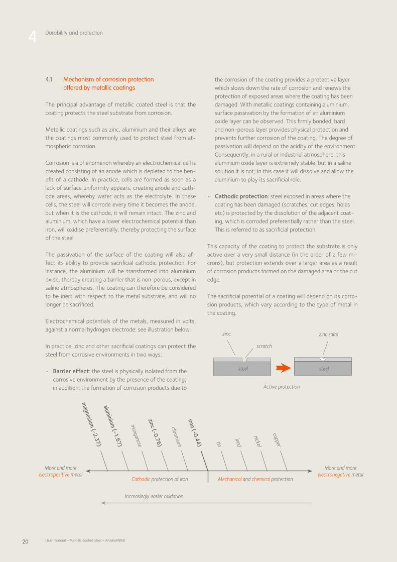
Electrochemical potentials of the metals, measured in volts, against a normal hydrogen electrode: see illustration below.
In practice, zinc and other sacrificial coatings can protect the steel from corrosive environments in two ways:
• Barrier effect: the steel is physically isolated from the corrosive environment by the presence of the coating; in addition, the formation of corrosion products due to
the corrosion of the coating provides a protective layer which slows down the rate of corrosion and renews the protection of exposed areas where the coating has been damaged. With metallic coatings containing aluminium, surface passivation by the formation of an aluminium oxide layer can be observed. This firmly bonded, hard and nonporous layer provides physical protection and prevents further corrosion of the coating. The degree of passivation will depend on the acidity of the environment. Consequently, in a rural or industrial atmosphere, this aluminium oxide layer is extremely stable, but in a saline solution it is not; in this case it will dissolve and allow the aluminium to play its sacrificial role.
• Cathodic protection: steel exposed in areas where the coating has been damaged (scratches, cut edges, holes etc) is protected by the dissolution of the adjacent coating, which is corroded preferentially rather than the steel. This is referred to as sacrificial protection.
This capacity of the coating to protect the substrate is only active over a very small distance (in the order of a few microns), but protection extends over a larger area as a result of corrosion products formed on the damaged area or the cut edge.
The sacrificial potential of a coating will depend on its corrosion products, which vary according to the type of metal in the coating.
Active protection
zinc
scratch
zinc salts
steel steel
More and more electropositive metal
More and more electronegative metal
Cathodic protection of iron Mechanical and chemical protection
Increasingly easier oxidation
copper
nickel
leadtin
iron (-0.44)
chromium
zinc (-0.76)
manganese
aluminium
(-1.67)
magnesium
(-2.37)

21User manual – Metallic coated steel – ArcelorMittal
4.1.1 Galvanised coatings (hot dip and electrogalvanised)
In a galvanised coating, zinc hydroxide is formed first. Since it has poor conductivity, zinc hydroxide will slow down the corrosion process. However, the zinc hydroxide will dehydrate to form zinc oxide, which is a semiconductor. This therefore constitutes a less effective barrier and the corrosion process may accelerate.
In addition to the zinc oxides and hydroxides, zinc carbonates are the most abundant corrosion products of zinc when exposed to the atmosphere in an urban environment.
Depending on the environment, zinc hydrochlorides (marine environment) or zinc hydroxysulphates (industrial environment) may also be formed.
The porosity of these complex oxides, which varies according to their composition, has a strong influence on the progress of the corrosion process. Their stability is determined by the pH of the atmosphere to which they are exposed. It has been observed that zinc carbonates remain stable in the widest range of environments and also offer the best barrier effect, whereas chlorides and sulphates dissolve in acid environments.
It should also be noted that coatings applied by electroplating are thinner than hot dip galvanised coatings, which limits the barrier effect and cathodic protection they offer, and therefore their corrosion resistance performance.
4.1.2 Galfan
It has been demonstrated in the literature that the corrosion resistance of galfan is about twice that of a standard galvanised product, in any environment. This high performance without further coating is due to three main factors:• The zinc present on the surface corrodes first. The
proportion of aluminium in the coating therefore increases, and the coating becomes increasingly passive.
• The corrosion products formed are less porous than the pure zinc oxides and hydroxides, which retards corrosion.
• The eutectic microstructure has a lower reactivity than that of zinc, which also contributes to slowing down the speed of corrosion.
Consequently, the speed of corrosion of galfan is comparable to that of a continuously galvanised product in the early stages of exposure to the atmosphere, but it slows down as the coating is used up. In addition, the presence of large quantities of zinc in the coating also provides cathodic protection when the surface is damaged or cut edges are exposed.
The rate of corrosion of galfan is between one third and half of that of standard galvanised steel. The edges also show improved corrosion resistance compared with standard galvanised material, indicating that the coating provides better cathodic protection.
4.1.3 Magnelis®
In chlorine or ammonia environments, no other metallic coating offers better protection than Magnelis®.• In ammonia environments, the deterioration of the coat
ing occurs seven times more slowly with Magnelis® than with a standard zinc coating of the same coating thickness.
• In salt spray tests lasting eight months, no red rust was observed on Magnelis® samples with 20 micron coating thickness, whereas all other metallic coatings of the same thickness had between 10% and 100% red rust under the same conditions.
• After being exposed to an alkaline solution of 5% NH3 with pH 11.7, Magnelis® had the smallest weight loss compared to samples with other metallic coatings.
• In highly alkaline environments (pH between 10 and 13), Magnelis® demonstrates superior corrosion resistance compared to other metallic coatings.
In addition to being strengthened by cathodic protection equivalent to zinc coating, Magnelis® protects exposed cut edges with a thin zincbased protective film containing magnesium, which prevents corrosive reactions.
4.1.4 Aluzinc®
The various corrosion tests show that the surface corrosion resistance of Aluzinc® is excellent (about twice as good as that of galfan). This is due to the higher proportion of aluminium in the coating, which reduces its reactivity accordingly. The corrosion resistance nevertheless depends on the type of exposure to which the material is subjected; the use of Aluzinc® in extremely alkaline environments in particular (e.g. inside cattle sheds) is not recommended.
4.1.5 Alusi®
A film of aluminium oxide can form immediately on the surface of Alusi®. The presence of this film will prevent the coating from corroding preferentially, rather than the steel. Consequently, the coating provides no cathodic protection in a rural or industrial environment.
On the other hand, the aluminium oxide layer will not be stable when in contact with a saline solution and will dissolve, allowing the aluminium to play its sacrificial role and protect the steel.
22 User manual – Metallic coated steel – ArcelorMittal
This coating will corrode at a constant speed over time. It will display progressive passivation due to its stable, impermeable corrosion products, and corrosion creep from the cut edges will only develop slowly.
When exposed to an alternating cycle of exposure to a saline atmosphere and a dry atmosphere, Alusi® will corrode pref-erentially to the steel and form corrosion products which will progressively seal off damage to the coating during the dry cycles. In this case, the coating will protect itself and the steel substrate at the same time.
4.1.6 Alupur®
In the case of Alupur®, since aluminium oxidises even more readily than zinc, aluminium oxide Al2O3 is formed spontane-ously as soon as the aluminium comes into contact with the ambient atmosphere. The presence of this continuous film of alumina passivates the aluminium since it isolates the metal from the corrosive environment. Nevertheless, in certain environments (extremely acid or alkaline, presence of chlo-rides), this film will tend to dissolve, which will allow corrosion to progress more rapidly. Moreover, the natural film of oxide may show local thinning or a break and it may be polluted; any of these may lead to the development of pitting corrosion. In a saline solution, this layer of aluminium oxide will not be stable and will dissolve, allowing the aluminium to play its role as a sacrificial coating.
4.1.7 Conclusion
ArcelorMittal has built up a body of knowledge about the behaviour of metallic coatings on the basis of trials carried out in extreme marine, rural and industrial environments. These allow us to compare the different coatings: aluminised, Aluzinc®, Magnelis®, galfan and standard galvanised material.
To conclude, the protection and corrosion performance of a sacrificial metallic coating depends on the nature of the envi-ronment to which it will be exposed, and the composition of the coating. The type of environment to which the compo-nent will be exposed will determine which metallic coating is the most suitable.
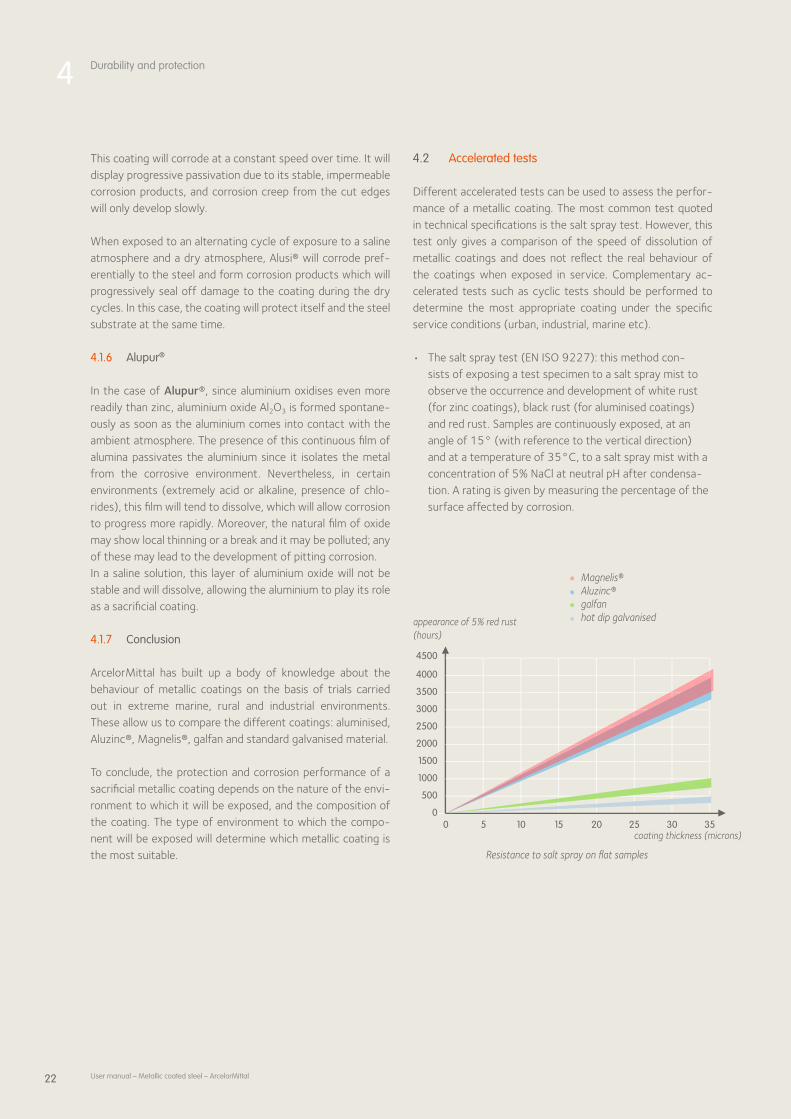
4.2 Accelerated tests
Different accelerated tests can be used to assess the perfor-mance of a metallic coating. The most common test quoted in technical specifications is the salt spray test. However, this test only gives a comparison of the speed of dissolution of metallic coatings and does not reflect the real behaviour of the coatings when exposed in service. Complementary ac-celerated tests such as cyclic tests should be performed to determine the most appropriate coating under the specific service conditions (urban, industrial, marine etc).
• The salt spray test (EN ISO 9227): this method con-sists of exposing a test specimen to a salt spray mist to observe the occurrence and development of white rust (for zinc coatings), black rust (for aluminised coatings) and red rust. Samples are continuously exposed, at an angle of 15° (with reference to the vertical direction) and at a temperature of 35°C, to a salt spray mist with a concentration of 5% NaCl at neutral pH after condensa-tion. A rating is given by measuring the percentage of the surface affected by corrosion.
50 10 15 20 25 30 350
500
1000
1500
2000
2500
3000
3500
4000
4500
Resistance to salt spray on flat samples
appearance of 5% red rust (hours)
coating thickness (microns)
Magnelis® Aluzinc® galfan hot dip galvanised
4 Durability and protection

23User manual – Metallic coated steel – ArcelorMittal
• The wet chamber test (KWT cyclic test, DIN EN ISO 62702): the sample is subjected to a temperature cycle over 24 hours: 8 hours at 40°C followed by 16 hours at 20°C. The cabinet is nonventilated and maintained permanently at 100% relative humidity (RH = 100%). A water reservoir ensures permanent condensation of steam on to the vertically positioned samples. The appearance and development of metallic coating corrosion products and red rust are then recorded.
4.3 Contact between metallic coatings and other materials
4.3.1 Contact with metallic materials
All contact with different metals produces a corrosion cell in a humid environment. This can be avoided by placing insulating material between the metal surfaces. Joining systems using bolts or rivets should include insulating disks between the bolts or rivets and the steel.
For the reasons set out above, all mechanical joining materials (bolts, nuts, disks, screws etc) should be made of noncorroding material, or protected for example by electro galvanisation.
4.3.2 Contact with non-metallic materials
Contact with solid or liquid nonmetallic materials ( concrete, plaster, seawater, animal excreta etc) may be a contra indication for use, depending on the nature of the metallic coating in question.See technical data sheets or contact our technical support teams for further information.

24 User manual – Metallic coated steel – ArcelorMittal

25
5Recommendations for transport, storage and primary transformation
5.1 General recommendations 26
5.2 Recommendations for transport and storage 26 5.2.1 Protection 26 5.2.2 Recommendations for transport and storage 26
5.3 Recommendations for decoiling, slitting, cutting to length, shearing and cutting 26
5.4 Durability of cut edges 27

26 User manual – Metallic coated steel – ArcelorMittal
5 Recommendations for transport, storage and primary transformation
5.1 General recommendations
A good production process is one that preserves all the initial properties of the metallic coated material. Essentially, this means the avoidance of excessive deformation or damage to the surface, to preserve its corrosion resistance properties.
5.2 Recommendations for transport and storage
5.2.1 Protection
Although this may appear paradoxical, metallic coated steel needs to be protected by additional treatment. In a confined atmosphere, a zinc based coating may corrode and form a corrosion product commonly known as white rust. Under the same conditions, metallic aluminium based coatings will develop corrosion products known as black rust. The space between two laps of a coil or between two sheets of steel in a package are areas where oxidation products may develop if storage conditions are poor.
To avoid these phenomena, additional protective treatments are recommended, such as oiling, chemical passivation or thin organic coatings, which will guarantee excellent temporary or permanent protection against corrosion.
Chemical passivation treatments performed at the mill reduce the risk of oxidation of the metallic coating. Depending on the conditions of transport and storage, they will remain effective for 3 to 6 months.
5.2.2 Recommendations for transport and storage
Some simple but essential precautions should be taken for the transport and storage of metallic coated steel:• Coils, sheets and blanks should be kept in air conditioned
storage facilities to ensure that no moisture accumulates.• In particular, coils, sheets and blanks should not be stored
near windows, doors etc, to avoid extreme variations in temperature which could produce condensation.
• During transport, and if outdoor storage is unavoidable, the coils, sheets and blanks should be protected.
• Avoid storing the products directly on the floor.
5.3 Recommendations for decoiling, slitting, cutting to length, shearing and cutting
The drive system for decoiling must be adjusted to match line speed in order to optimise product flow. In extreme circumstances on some processing lines, the drive system will also eliminate jerking, flapping and slippage of adjacent laps.
For slitting and other cutting operations, tools should be correctly adjusted and sharpened so as to minimise the formation of burrs.
Slitting, cuttingtolength and shearing operations should be included in process design from the outset, to ensure that any burrs which may result do not detract from the appearance of the piece or represent a safety risk during handling. The following rules should be observed to control the location of burrs after cutting.
Slitting and side trimming wheels should preferably be mounted symmetrically.
Symmetrical mounting of slitting blades
Non-symmetrical mounting of slitting blades
lower shaft
upper shaft
lower shaft
upper shaft
front side
reverse side
burr orientation
Burr orientation after slitting
Symmetrical mounting produces burrs positioned as shown in the diagram below.

27User manual – Metallic coated steel – ArcelorMittal
Horizontal and vertical blade clearances for slitting are shown in the following figure.
Cutting to length on a shearing line gives burrs oriented in opposite directions on the two cut edges of the sheet. This aspect is important, since it means that it is essential to stack the sheets perfectly vertically.
The use of disk cutters and similar techniques is not recommended, since they produce burrs and chips.
Laser or plasma cutting techniques can also be used. Their advantages are high precision and the absence of burrs.
5.4 Durability of cut edges
The zinc provides cathodic protection of the steel, particularly for the cut edges, where the bare steel is exposed after cutting.
The durability of the sheared edges is linked to the amount of zinc in the coating in relation to the thickness of the steel sheet. Large sheet thicknesses and low zinc content in the coating are unfavourable for the corrosion resistance of the cut edges. It should be noted that the critical thickness limits of the substrate with respect to corrosion must be established in each case individually, depending on the application.
The cutting technique employed also influences the corrosion resistance of the cut edges.
After shearing, the cut edge typically shows:• A glossy zone with little roughness (shear zone).
This deformation is also accompanied by pasting of the zinc in this zone.
• A matt zone (fracture zone) which has been disturbed by tearing, with a high degree of roughness and where the zinc is absent.
glossy zone coated with zinc
matt zone without zinc
Cut edge (sheared)
Optimum industrial cutting processes produce cut edges with 1/3 shear zone and 2/3 fracture zone.
Other methods of cutting are also favourable to the corrosion resistance of the cut edges.
The slitting quality is considered to be good if:• The distorted zone is small• The shear zone is roughly a third of the thickness• The fracture zone is sharp, with an angle of less than 5°• There are few or no burrs
upper shaft
blade
steel sheet
blade
vertical clearance (crossover)
horizontal clearance (between steel)
lower shaft
Horizontal and vertical blade clearances
steel sheet
Morphology of the cut edges
distorted zone (plastic rounding)
shear zone
fracture zone
little or no burr formationhorizontal clearance
6 to 8%
25 to 40%
50 to 60%
α = 5°
blank holder
uncoiled strip
fixed blade
moving blade
blank
Orientation of burrs after shearing

28 User manual – Metallic coated steel – ArcelorMittal
Laser cutting produces cut edges with a corrosion resistance equal to that of sheared edges.
Plasma cutting improves the durability of the cut edges, as a result of the formation of a protective layer of iron oxide after cutting.
Certain cutting techniques reduce the durability of the cut edges. Disk cutting undermines the corrosion resistance of the cut edges. The zinc is removed from the rim of the cut edges, and it produces burrs and a high degree of roughness.
Water jet cutting reduces the corrosion resistance of the cut edges by producing an extremely rough cut surface without any zinc coating.
5 Recommendations for transport, storage and primary transformation

29
6 Forming
6.1 Introduction 30
6.2 Bending 30
6.3 Roll forming 32 6.3.1 Description 32 6.3.2 The roll forming process 32 6.3.3 Roll forming production capacities 33 6.3.4 Basic rules 33
6.4 Deep drawing 35 6.4.1 The mechanical properties of steels 35 6.4.2 Different deformation modes 36 6.4.3 Forming limit curves 36 6.4.4 Friction and lubrication 37 6.4.5 Behaviour of metallic coated steel 38

30 User manual – Metallic coated steel – ArcelorMittal
6 Forming
6.1 Introduction
There are three groups of forming operations for metallic coated steel:• Bending, cambering, embossing, notching and hemming,
which are the most common processing operations for thin sheet (thin steel constructions, small boilermaking items, metal windows)
• Roll forming as a continuous process, on wide or slit strip• Forming operations using presses, mainly deep drawing,
used mainly in the automotive industry In most cases, it is possible to switch from uncoated to coated steel without any substantial modifications to operating conditions for these different forming processes. For the most common operations, there is very little difference in behaviour between metallic coated steel sheets and uncoated steel sheets.
Nevertheless, to take maximum advantage of the properties of these products, one should take into account the special surface characteristics of coated products.
These surface characteristics often include an advantageous lubricating effect due to the presence of the coating, especially when the pressure exerted is low or moderate. On the other hand, when the pressure exerted is higher, the coating may stick to the tool and be pulled off.
The forming limit of a coated sheet can be determined according to the type of forming operations and the plastic deformation modes can be generated by one of the following mechanisms:• Cracking or peeling of the interface layer between the
coating and the steel, which is the least ductile zone. This may occur if bending is too severe or as a result of a critical combination in deep drawing and expansion mode.
• Excessive thinning of the coating layer, which will affect corrosion resistance.
• Damage to the steel substrate when its forming limit is reached, such as rupture, necking or wrinkling.
Successful forming of a metallic coated steel sheet therefore depends on the choices made in terms of component design, the steel grade, the type of coating and the quality of the tools used.
6.2 Bending
In conventional sheet steel processing, bending is the most severe operation and determines the steel grade to be selected.
During the bending process, the metal is bent over the tool; if there is no friction or external tension, there should be an equilibrium between the elongation of the exterior fibres and the compression of the interior fibres. But friction detracts from the compression of the latter and tension increases the exterior fibres’ tendency to elongate. The neutral fibres move in the direction of the tool and the sheet becomes thinner. This thinning naturally results in a loss of strength, and any tension applied would soon cause rupture, if the resistance of the metal to deformation had not been increased by workhardening. The important property is therefore its workhardening capacity, indicated by the strain hardening coefficient n.
Different bending techniques may be used: narrow punch Vbending, flap bending, automatic panel forming or edge forming.
Narrow punch V-bending Flap bending
Bending on a panel forming machine

31User manual – Metallic coated steel – ArcelorMittal
The bending limit can be expressed as the minimum diameter (interior of the bend) which can be achieved without peeling of the coating, or detectable tears or cracks. This limit depends, of course, on the thickness of the sheet and of the coating, and also on the steel grade.
Electrogalvanised steel: the excellent adherence of the coating to the substrate, the extreme thinness of the coating and the absence of an intermetallic layer of alloy give electrogalvanised steel excellent forming properties. This product can be formed by 180° folds in the same way as uncoated steel.
Galvanised steel: in general, the bending performance of galvanised steel (pure zinc) can be regarded as identical to that of uncoated steel for thicknesses under 3 mm and coating weights of up to 275 g/m2.
The pictures below show the difference in bending behaviour between galvanised steel without lead and galvanised steel with lead, after bending. The numerous cracks in the coating containing lead are clearly visible. However, if there is no lead in the coating, bending and even severe 180° folds, present no problems.
Bending processes performed on presses require higher blank holder pressures than with uncoated steel to counteract the greater risk of slip.
Galfan: the intermetallic layer FeAl3 is thinner than that of galvanised steel Fe2Al5. The lamellar structure of the eutectic and the thin intermetallic layer give the coating very good forming properties.
Magnelis®: has good formability, equivalent to traditional galvanised steel. Cracking may occur if the bending radius is less than twice the thickness of the sheet.
Aluzinc®: it has good formability; severe bending may cause cracking of the intermetallic alloy layer but these cracks generally do not reach the surface of the coating. A bending diameter of at least twice the thickness of the metal is recommended.
Alusi®: the bendability of Alusi® coatings is equivalent to that of classical galvanised steel. The presence of an intermetallic layer of alloy rules out severe forming because of the risk of cracking the coating.
Alupur®: the forming performance of Alupur® is limited to nonsevere bending, because of the presence of a very thick, fragile intermetallic alloy layer (Fe2Al5).
Sheet thickness < 1.25 mm > 1.25 mm
Bending diameter 6 x thickness 8 x thickness
Bending limits of Alupur®
With lead
Without lead

32 User manual – Metallic coated steel – ArcelorMittal
6.3 Roll forming
6.3.1 Description
Cold roll forming is a continuous process for forming flat carbon steel in sheets or coils to obtain products with a constant crosssection, referred to as profiles.
These profiles can be divided into three broad groups:
• Wide profiles: these are very wide products (about 600 to 1500 mm) with several waves of the same or a similar shape. The major products in this group are profiles for roofing and cladding.
• Tubes: these are products with a closed crosssection produced by roll forming and continuous welding.
• Narrow profiles: these are products with an open or closed crosssection, without welding, and with no repetitive waves. This group includes profiles for structures, cable gutters, crash barriers etc.
6.3.2 The roll forming process
Roll forming can be seen as a continuous bending process. The steel sheet undergoes progressive plastic deformation as it passes successive rolls, until the required angle and shape are obtained.
The most important advantage of roll forming in comparison with bending is the high production speed.
6 Forming
The roll forming process
The roll forming process
The shape of the bent metallic coated steel at each roll or roll forming pass defines the roll forming flower. This is fundamental since it defines the order in which the bends are made as well as the values of the bend angles.
bending roll forming
Roll forming and bending

33User manual – Metallic coated steel – ArcelorMittal
More generally, roll forming of a product on a specified machine is characterised essentially by:• The roll forming flower• The number of passes or rolls used (this is defined
indirectly by the roll forming flower)• The distance between the rolls on the roll forming
machine• The vertical position of the steel sheet in the
roll forming machine• The clearance between the rolls• The lubrication
6.3.3 Roll forming production capacities
Roll forming is a highly flexible process. This is reflected in the production volumes attainable, the shapes that can be formed – even if they have to maintain the same crosssection over the whole length – and also with respect to:
• Thickness: which may vary between 0.15 mm and 12 mm.
• Width: there is no minimum width dictated by coil slitting capabilities. The maximum width for roll forming is simply the maximum coil width which can be produced, which is 2060 mm in our current product range.
• Length: there is no specific maximum length for profiles. In practice, the length of products is limited to what can be handled, transported etc.
• Steel grades: very ductile grades with a low yield strength (around 150 MPa) can be used, as well as very hard grades with yield strengths of 1000 MPa and over. By using suitable technology, it is perfectly possible to produce high quality profiles using all grades of steel presently available.
• Steel type: the steel type – hot rolled, cold rolled, galvanised etc – makes relatively little difference for the roll forming process. However, mixing steel types is certainly not recommended. Since pollution of the tools is inevitable, care must be taken not to transfer pollution from one product to another.
The biggest restriction on what can be produced by roll forming is that the product must have a constant shape over its whole length, which does not rule out curved products.
6.3.4 Basic rules
To obtain quality products using the roll forming process, a number of basic rules should be respected. These concern various phenomena which occur during the process.
Transverse forming
To produce a profile from a flat steel sheet, it has to be bent and therefore the sheet has to undergo local plastic deformation in a transverse direction. The level of these plastic deformations ε depends primarily on the geometrical design of the final products. They can therefore be expressed approximately by means of the following formula:
ε = t
2R
Rule No. 1
To avoid cracking of the coating and corrosion of the pro-file when in use, the geometry of the profile should have the lowest t/R ratio possible, i.e. with large radii in rela-tion to the thickness of the material.
Longitudinal deformation
The main difficulty encountered in roll forming is a correct control of the twisted zones of the steel sheet in the roll forming machine. Twisted zones are inherent in the process and cannot be eliminated. But they can be limited and in some cases, distributed correctly over the sheet. The longitudinal deformations generated by twisting of the steel sheet in the roll forming machine must remain within the elastic range of the material. If this is exceeded, plastic deformation of the material will take place. The steel sheet will elongate locally in an irreversible manner in the longitudinal direction and twist as it comes off the roll forming machine.
The roll forming flower
Transverse forming
whereby: t = thickness of the material R = bending radius
ε
R
t
ε

34 User manual – Metallic coated steel – ArcelorMittal
6 Forming
It is therefore necessary to ensure that:
ε longitudinal ≤ Rp0.2
E
where: Rp0.2 = yield strength of the steel E = Young’s modulus for steel
This is why it is preferable to select steel grades with a high yield strength for roll forming. Raising the yield strength of the material enlarges the domain in which longitudinal deformations will remain elastic.
Knowledge of these longitudinal deformations is therefore essential, but they are unfortunately difficult to predict, since very precise data is needed on the shape of the steel sheet during the process.
However, finite element simulation using dedicated software can predict these longitudinal deformations. For prototyping and simu lations, ArcelorMittal has software which can also be used to define the most appropriate roll forming flower adapted to the capabilities of a specific roll forming line.
Rule No. 2
Do not exceed the yield strength of the material for lon-gitudinal deformations. Adjust the roll forming flower and/or the design of the profile if necessary. Use a mate-rial with a higher yield strength if needed.
Rule No. 3
To distribute the longitudinal deformations over the larg-est possible area, select the largest possible roll diameter and a sufficiently large distance between two sets of rolls (over 1.5 times the length of deformation for narrow profiles).
Speed of the steel sheet and the rolls
Firstly, one should never forget that the steel sheet moves forward purely through friction with the tools in the roll forming machine. If friction was reduced to zero, the roll forming process would cease to function.
The first difficulty is to ensure that the steel sheet proceeds at a uniform or slightly progressive speed over the whole length of the roll forming line. This avoids panel buckling or conversely, excessive tension.
The second difficulty is to ensure that there is friction between the steel sheet and the tools without slip. If a tool slips over the steel sheet on the roll forming line, there will be a significant risk of mechanical damage at that point.
Rule No. 4
Ensure that the steel sheet moves at a constant or slightly progressive speed. In order to obtain this, select the same diameter for all the driving rolls and mount the other rolls on bearings.
Rule No. 5
Compensate for differences in speed at each roll by us-ing bearings or suitable lubrication. ArcelorMittal offers Easyfilm®, a thin organic coating on a metallic coated sub-strate which has proven advantages in the roll forming process since it provides uniform lubrication.
Springback
Springback is dependent to a large extent on the geometry of the profile and radii in particular, as well as on the type of material used and its yield strength.
Rule No. 6
To reduce springback, the section should be designed with small radii and a large thickness, specifying a steel grade with a low yield strength. To avoid contravention of rule No. 1, it is sometimes possible to exceed the nominal value of the bend radius required in the finished part to control this phenomenon (by using an “overforming” roll).
The influence of roll diameter
after the roll before the roll
deformation length
under the roll

35User manual – Metallic coated steel – ArcelorMittal
Contradictory requirements in roll forming
For a successful roll forming operation, the above rules should be respected.
However, these rules are sometimes contradictory, and the designer is faced with difficult choices. The table below summarises these incompatibilities:
Corrosion resistance
Control of springback
Control of longitudinal
deformations
Speed control
Increasing bend radius ▲ ▼ = =
Increasing thickness ▲ ▼ = =
Increasing yield strength = ▲ ▼ =
▲ better ▼ worse = no change
This table highlights the two main contradictory principles of controlling roll forming.
The first contradiction concerns the selection of the yield strength. Roll forming needs a steel with a high yield strength to avoid longitudinal plastic deformation. However, for deformation in the transverse direction, a low yield strength would be preferable, to obtain minimal springback. In view of this, the best solution is to opt for a relatively “hard” grade to reduce longitudinal plastic deformation, and control springback by using an overforming roll.
The second contradiction concerns the bend radii and the thickness of the steel. To ensure that the profile has good corrosion resistance in service, designers should prefer large bend radii and small thicknesses. To reduce springback, precisely the opposite is required. The final choice depends on the future use of the product and the coating selected. The geometry should be designed with the smallest possible bend radii and the largest thickness compatible with the required corrosion resistance. Regarding the latter, one should not forget that the thickness of the steel substrate is a determining factor in the mechanical resistance of the profile.
6.4 Deep drawing
Deep drawing is the manufacturing process which allows us to exploit the formability of a steel sheet to the maximum, and the development of socalled deep drawing grades is based on this process, which is executed using a tool consisting mainly of a punch, a die and a blank holder, used in a press.
The deep drawing process
punch
blank
diedeep drawn part
blank holder
The success of a deep drawing operation depends on the optimisation of manufacturing parameters and meticulous finetuning.
The material itself is obviously the first of the many parameters that can be adjusted. The choice of a steel grade to produce a given shape depends initially on the assumption that the properties of the finished piece will be such that it can withstand the stress which the specifications generate. Regarding the forming it will undergo, this means that the formability of the steel (rheological aspect) and its surface properties with respect to contact between the steel and the tool (tribological aspect) must be appropriate for the shape to be produced, the required appearance of the final product, and the expected cost.
6.4.1 The mechanical properties of steels
When envisaging forming steel sheets, one should remember that they will react very differently, depending on how the stress or strain are applied.
The most commonly used mechanical properties are those which can be determined by a uniaxial tensile test. This test has the advantage of being simple to execute and providing a large amount of data at the same time. The following mechanical properties can be determined by this test: • Re, yield strength, after which deformation becomes
plastic and therefore permanent• Rm, ultimate tensile strength or breaking load• A%, elongation at rupture• r, Lankford coefficient, which expresses the ratio of
transverse strain to thickness strain for a given elongation (usually 20%). It gives a good idea of the ability of the

36 User manual – Metallic coated steel – ArcelorMittal
sheet to deform in deep drawing mode and varies according to the direction in which the test specimen is taken from the sheet.
• n, strainhardening coefficient, which indicates the steel’s ability to harden when plastic deformation takes place
These properties only represent an imperfect description of the behaviour of the steel in one simple example of forming operation: uniaxial tension.
6.4.2 Different deformation modes
There are three deformation modes: expansion, deep drawing and plane strain mode.• Expansion is characterised by an increase in the surface
area of the steel sheet and therefore a reduction in thickness (since the volume of the material remains the same), which can lead to a fracture of the steel in extreme cases. This deformation mode can be seen in the “top section” of the deep drawn component in the figure.
• Deep drawing mode is caused by a compressive stress in the steel sheet, which may lead to an increase in the thickness of the material or wrinkling.
• Plane strain mode is observed in the “central zone” of the deep drawn part. This zone cannot become narrower, nor
wider, as in expansion mode. This zone elongates, but the width does not vary. Plane strain mode is the most critical deformation mode (lowest point in the Forming Limit Curve).
These three deformation modes coexist during the drawing pro cess; the solution is to find the best compromise between deep drawing mode (wrinkling), expansion and plane strain mode (rupture or necking).
6.4.3 Forming limit curves
Two methods exist to express these variations in mechanical properties:• By evaluating the stresses; various plasticity criteria
(Tresca, Von Mises, Hill etc) enable to calculate the laws of behaviour of the metal in all deformation modes, starting with simple uniaxial tension.
• By evaluating the deformation; an indispensable indicator is used in this field: the Forming Limit Curve or FLC.
For a steel sheet of a given grade and thickness, the FLC determines a safety limit for deep drawing operations, superimposed on strain values representing the deformation as a whole. This curve can be established according to various criteria of acceptability: necking or fracture of the steel, wrinkling, excessive thinning of the metallic coating, cracking or peeling of the coating etc.
This curve allows the user to:• Evaluate the safety margin of the drawn component• Identify critical areas of the component where the
material is subjected to severe deformation• Analyse the factors which influence forming: steel grade,
component design, lubrication, tool design (restraining draw beads, radii etc)
The figure gives an example of a Forming Limit Curve for coated steels; criteria regarding damage to the coating and
expansion
plane strain
deep drawing mode
Different deformation modes in a drawn component
6 Forming
FLC of lead-free galvanised steel Z225 (grade S320GD+Z, thickness 0.7 mm)
major strain e1 (%)
minor strain e2 (%)
limit of damage to the coating
necking limit of the steel substrate
type A (slight cracking)
type B
success
flaking
type B
type A
flaking
width of surface crack (µm)
50
40
30
20
10
0-20 -10 0 10 20 30
e1=e2
e1=e2
5
1020
30

37User manual – Metallic coated steel – ArcelorMittal
the necking limit of the steel substrate have been taken into account.
The upper curve of the zone represents the necking limit of the steel substrate.
The lower curve shows the limit of the deformation zone below which no damage to the coating arises. Between these two curves, damage to the coating will occur (shallow to deep cracking and possibly flaking).
6.4.4 Friction and lubrication Friction
Contact between the metal and the tool often plays an important role in the forming of flat carbon steel products because it causes a dissipation of energy through friction. This friction affects not only the final condition of the surface, but also the local material flow; it therefore often influences the geometry of the product, as well as its mechanical properties.
The friction coefficient µ is the ratio between the force necessary to move an object over a surface and the weight of that object. In the deep drawing process, the force is provided by the punch and the “weight” by the gripping of the steel sheet in the blank holder. The friction coefficient is a result of the nature of the two surfaces in contact with each other (type of material, roughness etc), the temperature and the presence of any other entity such as oil or particles of coating which have been torn off.
The modifications that can be made to the tool are limited by the geometry of the final component. But it should be noted that the condition of the surface of the tools is extremely important. It is desirable to aim for very low roughness values (Ra) of the tools, in the order of 0.2 to 0.3 µm.
Restraining system
punch blank holder
restraining draw bead die
Lubrication
Lubrication plays a very important role in the deep drawing pro cess, and good lubrication is often the key to success.
There are three regimes of lubrication:• The hydrodynamic regime, characterised by the absence
of contact between the steel sheet and the tool; the steel sheet rests on a continuous and relatively thick film of oil and the friction coefficient is very low.
• The boundary regime, where the film of oil is very thin; in this case there is contact between the roughness peaks of the steel sheet and the tool, and the coefficient of friction is therefore very high.
• The mixed regime is in between these two regimes. In certain zones, the steel is in direct contact with the tool, and elsewhere it rests on a film of oil. The friction coefficient therefore varies between these two extremes.
In the deep drawing process, lubrication is generally of the mixed type, or critical in certain zones. Polishing radii and draw beads is therefore extremely important, for two reasons:• Contact pressures are very high, and this can damage the
surfaces (scratching or tearing off the coating, wear or damage of the tools).
• To obtain a mixed regime of lubrication, the oil must be introduced under pressure into the “valleys” of the roughness profile of the coating. The presence of scratches on the tools must be avoided at all costs.
The mixed lubrication regime is a very unstable mode, and very sensitive to process adjustments and the state of the tools. This calls for preventive maintenance of the tools and careful control of the processing parameters.
steel sheet
tooldisplacement
boundary regime
lubricant
hydrodynamic regime
mixed regime
Lubrication

38 User manual – Metallic coated steel – ArcelorMittal
The everexpanding range of coated products available presents a fairly marked dissimilarity in the tribological behaviour of the different products. The nature of the coating itself has a very significant effect on the tribological behaviour of a product and therefore its formability.
Extensive research has shown that the influence of the roughness of the steel sheet is of secondary importance with respect to lubrication.
Galling
Coating particles torn off the steel and deposited on the deep drawing tool cause galling marks. This is the result of an anomaly (a hard spot, scratch, sharp edge of a tool, the systematic formation of wrinkles in the same place, casting defects or buildup of polluting particles in the tool). All these anomalies lead to extremely high local pressure and therefore boundary regime conditions. The surface of the tool then deteriorates rapidly, the friction coefficient increases and finally the steel sheet cracks.There are various solutions to avoid galling:
• Rigorous maintenance of the tools: polishing the radii, regular cleaning
• Use of tools with a very hard coating: chrome, titanium nitride, titanium carbonitride
• Use of steel sheets with appropriate roughness; deep “valleys” can trap debris or particles of coating
Oiling
Another area of progress is the lubricants themselves. The aim is to ensure that there is a film of oil between the steel and the tool at all times. For this, we need high performance oils and uniform and constant oiling of the blanks. The best solution is to “wash the blanks” and deep draw them in one operation.
When finetuning the process, it is just as important to have full details of the lubrication (type of oil, how many grams/m2, distribution) as it is to know the properties of the steel.
Oil migration
Oil migration refers to the spontaneous disappearance of oil on coated and oiled coils or sheets. It generally occurs over various zones, and this inevitably means that different tribological properties are found in some areas of the steel sheet, which causes problems with galling or rupture. This is a phenomenon which specifically affects coated steel; it depends on the duration and conditions of storage, the type of oil used and the properties of the steel (flatness, roughness etc). Oil migration can be prevented by the use of dry lubricating films.
6.4.5 Behaviour of metallic coated steel
Zinc based coatings (Z, ZE, ZA) are ductile coatings which can undergo severe deformation (Vickers hardness 5070 HV, compared to 100 HV in the case of uncoated steel).
The choice of materials for the tools and their surface treatment (steels alloyed with chrome or hard chromium plated) are contributory factors affecting the investment costs, the cost of maintenance and the production speed.
With our long experience in the field, the ArcelorMittal teams can help customers select the optimum solution for their requirements. Component design and the offer in deep drawing steel grades have a considerable effect on the durability of the components in service. ArcelorMittal has simulation software which enables us to define the optimum forming range. Contact us for further information.
plateau valley
steel sheet
trapped debris
tool
micro-weld
debris
tool imperfection tears off
fragments of coating
lubricant transports debris
to the valley
debris
Galling
6 Forming

39
7 Joining
7.1 Adhesive bonding 40
7.2 Clinching 41
7.3 Riveting 41
7.4 Lock seaming 42
7.5 Joining with bolts, studs, clips etc 43
7.6 Welding 43

40 User manual – Metallic coated steel – ArcelorMittal
7 Joining
7.1 Adhesive bonding
Joining by adhesive bonding consists of bonding the two surfaces together by means of an adhesive.
This method of joining can be adapted to suit all types of material and one of its advantages is that it can be used to join materials of different types or thicknesses.
In order to ensure good adhesion and cohesion in the bond, the compatibility of the adhesive with the metallic coating must be ascertained prior to use. This aspect must be examined in detail, since each combination of metallic coating/surface treatment/adhesive has its own performance characteristics. An adhesive bonded structure is a complex composite system whose efficiency depends not only on the choice of adhesive but also on the cohesion of all the constituent layers.
In general, epoxy adhesives give better results than acrylic or polyurethane adhesives for bonding electrogalvanised and galvanised coatings. They present a better aging performance and appear to reach a stable state after a week. However, it should be noted that coatings with a higher aluminium content, such as galfan, give very good bonding results with acrylic and polyurethane adhesives, but not with epoxy adhesives.
The various joins examined showed that electrogalvanised substrates produced a better bonding performance than galvanised substrates. Skinpassed galvanised steel shows an intermediate level of reactivity, between that of electrogalvanised steel and nonskinpassed galvanised steel.
Each bonding project is unique and requires its own specific solution. Please contact our Customer Teams to determine the solution for your particular project.
Polymerisation of the adhesive can be performed efficiently and rapidly by various techniques, either chemically (by means of a catalyst or activating agent) or thermally (by using an oven, heating press, induction, infrared heaters etc).
In order to facilitate handling of the component before polymerisation is complete, clinching or other similar joining procedures can also be used.
From a mechanical point of view, the joint may fail in the adhesive layer, in the metallic coating or at one of the interfaces (steel/metallic coating/adhesive). In addition, the durability of the bond will also vary according to the environment to which the finished component is exposed.
Conventional adhesive bonded joints are generally lap joints.
Resistance to shear and compressive stresses is higher than resistance to peeling and cleavage, which should be avoided.
lap
join
t
butt
join
t
Recommended adhesive bonded joint configurations
This method of joining presents many advantages. Loads are spread perfectly as a result of the continuous bond created. Unlike mechanical joining techniques such as riveting or bolting, this method of joining is aesthetically pleasing, the substrates undergo no mechanical or thermal damage and the metallic materials are protected from corrosion. Loads are spread evenly and it can potentially contribute to vibration damping.
Adhesive bonding has three limitations: the necessity of holding the components in place while the bonding takes place, the fact that the join cannot be disassembled after bonding, and the ageing of the adhesive and its resistance to fire and high temperatures.
compression shear tension
cleavage peeling
Different types of joint loading

41User manual – Metallic coated steel – ArcelorMittal
7.2 Clinching
Clinching is a joining process that involves locally deforming the material of two or more sheet parts using a tool set consisting of a punch and a die. In this way a joining element is formed.
The metallic coating is only of minor significance in the clinching process. It has little influence on loading parameters and the choice of tools. Nevertheless, it has sometimes been observed that the mechanical performance of the join with metallic coated steel may be very slightly inferior to that of a similar steel without a metallic coating. This is probably due to the fact that the coating is more ductile than the steel substrate and therefore acts as a lubricant.
7.3 Riveting
There are various different riveting techniques:
• Conventional riveting, whereby holes are drilled before the rivet is introduced and deformed.
rivet
• Blind riveting, for which only one side of the joint needs to be accessible, since the hollow rivet is deformed by a central shaft. There are various different models, including systems in which the head or shaft snaps, and explosive head and threaded shaft types of systems.
• Self-piercing rivets, with which riveting can be performed in a single operation, since the rivets drill their own holes.
This procedure allows materials of a different nature to be joined, and also nonweldable materials (organic coated steel). It does not require prior drilling of the component or the use of additional material. Since the join does not need to be heated, there is no thermal damage.
With suitable precautions, it preserves the corrosion resistance of the coatings; it has been observed that even after joining, the coating may in some cases be thinner but it is still present over the entire surface of the clinched point. It is a clean process that produces no fumes or slag; it is relatively quiet and uses little energy. It can be easily automated and easily integrated into various types of manufacturing line, such as roll forming.
Regarding the appearance of the component, each clinching point produces a hump and a hollow, which may limit its suitability for certain applications.
Since the static strength of a clinch is lower than that of a spot weld (3070% of spot weld strength), a greater density of clinch points is required. The clinching tool must be perfectly perpendicular to the sheets and the punch must be very precisely positioned with respect to the die.
The following guidelines must be observed for clinching:• The thinner sheet should not be less than half the thick
ness of the thicker sheet • The maximum thickness after joining is 6 mm• This maximum thickness decreases if the mechanical
properties of the steel increase The clinchability of a steel sheet is directly linked to the grade of steel employed. To guarantee the attractive appearance of the clinched points, total lubrication with a volatile oil may prove ne cessary to limit friction between the punch, the surface of the steel and the die.
Clinched point

42 User manual – Metallic coated steel – ArcelorMittal
7 Joining
These methods of joining with rivets can be used to join different types of material and also nonweldable material (with an organic coating).
This joining technique demands few special precautions with cold rolled, galvanised or electrogalvanised steel. The only point to remember is that if the rivet is made of a different material than that of the pieces to be joined, it is essential to take account of the possibility of galvanic corrosion. Beyond that, the nature of the metallic coating makes little difference for this joining technique.
The following guidelines should be observed:• With selfpiercing rivets, the maximum total thickness
of the join is 6 mm.• This maximum thickness decreases if the mechanical
properties of the steel increase.• These limitations do not apply to other types
of riveting techniques.• This technique is less suitable for thin sheets. The advantages of using selfpiercing rivets are similar to those of clinching. In addition, it also offers higher mechanical resistance, and in particular, resistance to static loading.
Joining with rivets does not damage the corrosion resistance of the coatings, since the entire exterior surface of the sheet remains protected by its coating. The part pierced by the rivet is protected by the presence of the rivet, which must guarantee that the joint is absolutely leaktight.On the other hand, the joints cannot be disassembled and they are aesthetically unattractive.
Riveting methods are relatively quiet, lowenergy processes.These processes can be easily automated, which make them competitive with other mechanical joining techniques. However, they do have the disadvantage of the additional cost of the rivets, unlike other techniques.
7.4 Lock seaming
Lock seaming covers all the mechanical joining methods which depend on the plastic deformation of at least one of the components to be joined.
Lock seaming can be used to join metallic coated steels, provided that suitable metallic coatings are chosen to withstand the strains generated in the folds (see properties of metallic coatings).It can easily be combined with adhesive bonding, and a leaktight seal can be guaranteed by the use of a sealing compound, an adhesive or a rubber seal.
As far as possible, the seam should be designed so that the cut edges are not visible, both for aesthetic reasons and for optimum corrosion resistance.
However, lock seaming is only suitable for parts with a geometrically simple design, and cannot be used for corners. The joints cannot be disassembled, and have a low resistance to slipping in a direction parallel to the folds and a low resistance to opening.
Different single and double lock seams

43User manual – Metallic coated steel – ArcelorMittal
7.5 Joining with bolts, studs, clips etc
With these methods, it is possible to join different types of products together. The joins can be easily dismantled, but they are not very attractive, even when covered by caps.
They represent a significant extra cost in terms of material and labour, and are difficult to automate. On the other hand, mechanical joining of this type is relatively quiet and consumes little energy.
7.6 Welding
Resistance spot welding
This is a complex process including electrical aspects (passage of an electric current), thermal (dispersion of calories), mechanical (application of significant pressure) and metallurgical aspects, whereby the aim is to induce heating by the passage of an electrical current, and then the local coalescence of the two steel sheets.
The electrical aspect of the process can be described as a succession of ohmic resistances, the relative values of which produce local heating. The strength of the contact resistance between the two sheets governs the formation of the weld nugget at the site of the spot weld.
This welding process can be used with all metallic coatings. But in comparison with uncoated steel, the addition of a metallic coating has two significant effects: it increases the current of the welding process (and/or the time taken) and it reduces the weldability ranges. The type of metallic coating (galvanised, galfan, Aluzinc®, aluminised, electrogalvanised) has relatively little influence on the formation of spot welds, as long as welding parameters (pressure, intensity etc) are adjusted in accordance with the thickness and the nature of the metallic coating. These parameters will optimise electrode lifespan.
Since zinc and copper have a great affinity, when heated, the electrode heads will be transformed progressively into brass, which has lower mechanical resistance than the copper alloy, and higher resistivity. This brass gradually disappears from the electrode heads by forming “collars” or by adhering to the surface of the welds, which causes thermochemical erosion of the electrodes.The nature of the metallic coating has a fundamental effect on the deterioration of the electrodes.
Since this deterioration of the electrodes is of a random nature, the use of a control box to regulate the welding current is recommended. For series of several hundred spot welds, it is also recommended to compensate the loss of density of the current in the electrode heads by increasing the strength of the welding current incrementally as a function of the number of points welded, together with regular cleaning of the electrode heads (reconditioning by means of a special milling process).
Optimum cooling of the welding electrodes by internal circulation of water at 20°C at a rate of 4 to 6 l/min will extend the lifespan of the electrodes.
The most suitable material for the electrodes is the class 2 alloy CuCrZr (NFA 82100).
pressure applied
current ON current OFF pressure ON
pressure released
electrodes
weld nugget
lap joint
electrode tip
weld nugget
electrodes
indentationsheet separation
heat-affected zone
electrodes
Spot welding
Various mechanical joining techniques (bolts, studs, clips etc)

44 User manual – Metallic coated steel – ArcelorMittal
7 Joining
Seam welding
As with spot welding, the electrodes are made of a class 2 alloy of CuCrZr, but in this case, the electrodes are in the form of wheels.
If possible, the seams should be welded discontinuously (Roll Spot), to limit heating of both the steel sheet and the electrodes (figure c)).
A variant of this process is to use an intermediate electrode with consumable copper wire (Soudronic patent). This method, which calls for a fairly precise guiding system for the placement of the copper wire, may be economically advantageous for the manufacture of large series of components, because when the welding parameters have been carefully optimised, this method can always guarantee excellent internal quality of the molten nuggets.
This technique can be used with steel thicknesses of up to 1.2 mm (e.g. for vehicle fuel tanks).
e)
extremely flat electrodes
sheet
workpieceprojections
force
force
product
weld nuggets
f)
g) weld nuggets
nut
h) weld nuggetsbolt
a)
c)weld nuggets
b)
d)
electrode wheels
electrode wheelsweld sheet
Projection welding
The projections are protuberances with controlled geometrical dimensions, formed by deep drawing or machining of one of the pieces to be joined. The passage of the welding current is localised to the right of the protuberance. Projection welding is an attractive alternative when welding relatively solid accessories on to a thin steel sheet, since the small volume of the protuberances will reduce the amount of heat taken up by the solid component during the welding process (e.g. mounting threaded nuts or bolts on car body parts: see figure g) and h)).
To avoid premature failure of the weld, the pressure on the electrode must be controlled perfectly. Welding time is usually short, particularly with thinner gauges of steel.
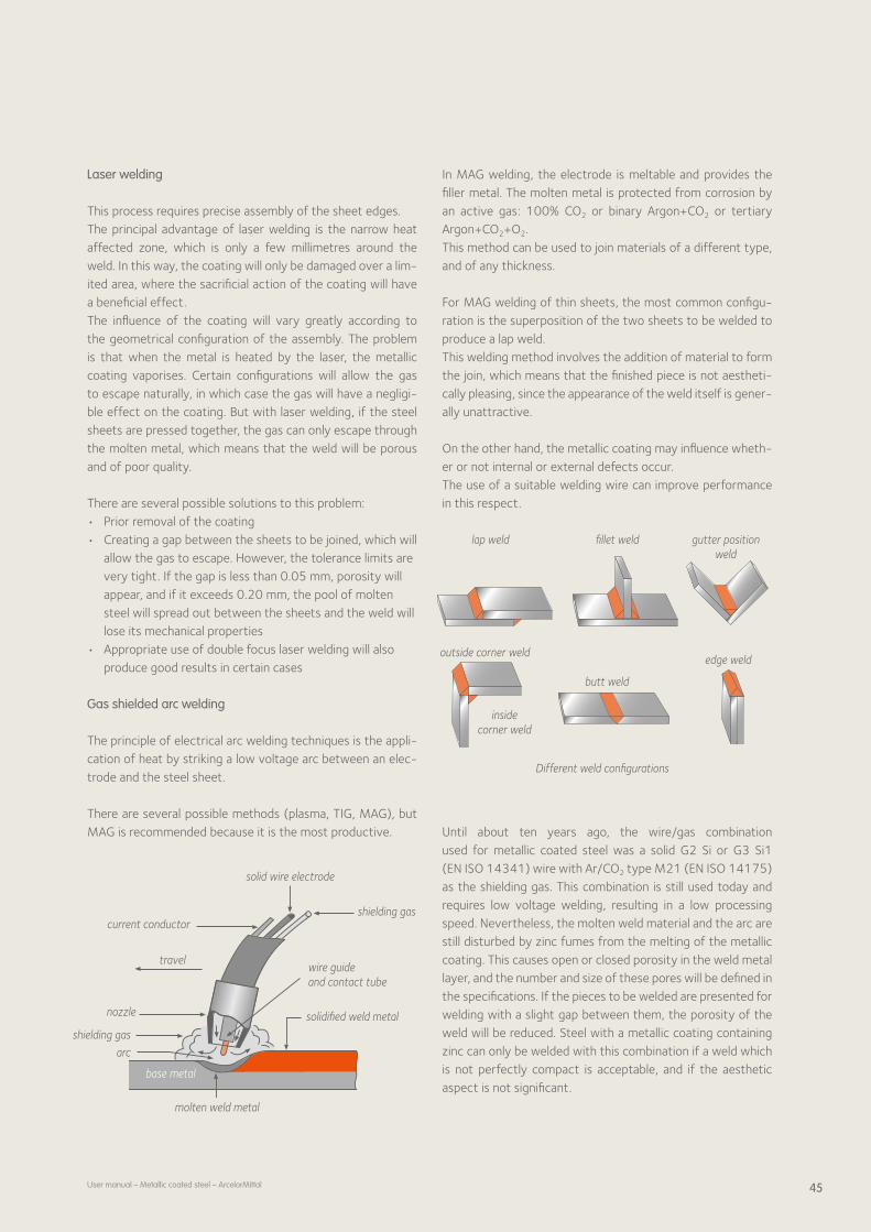
45User manual – Metallic coated steel – ArcelorMittal
lap weld fillet weld gutter position weld
outside corner weld
inside corner weld
butt weld
edge weld
Different weld configurations
Laser welding
This process requires precise assembly of the sheet edges.The principal advantage of laser welding is the narrow heat affected zone, which is only a few millimetres around the weld. In this way, the coating will only be damaged over a limited area, where the sacrificial action of the coating will have a beneficial effect.The influence of the coating will vary greatly according to the geometrical configuration of the assembly. The problem is that when the metal is heated by the laser, the metallic coating vaporises. Certain configurations will allow the gas to escape naturally, in which case the gas will have a negligible effect on the coating. But with laser welding, if the steel sheets are pressed together, the gas can only escape through the molten metal, which means that the weld will be porous and of poor quality.
There are several possible solutions to this problem:• Prior removal of the coating• Creating a gap between the sheets to be joined, which will
allow the gas to escape. However, the tolerance limits are very tight. If the gap is less than 0.05 mm, porosity will appear, and if it exceeds 0.20 mm, the pool of molten steel will spread out between the sheets and the weld will lose its mechanical properties
• Appropriate use of double focus laser welding will also produce good results in certain cases
Gas shielded arc welding
The principle of electrical arc welding techniques is the application of heat by striking a low voltage arc between an electrode and the steel sheet.
There are several possible methods (plasma, TIG, MAG), but MAG is recommended because it is the most productive.
In MAG welding, the electrode is meltable and provides the filler metal. The molten metal is protected from corrosion by an active gas: 100% CO2 or binary Argon+CO2 or tertiary Argon+CO2+O2.This method can be used to join materials of a different type, and of any thickness.
For MAG welding of thin sheets, the most common configuration is the superposition of the two sheets to be welded to produce a lap weld. This welding method involves the addition of material to form the join, which means that the finished piece is not aesthetically pleasing, since the appearance of the weld itself is generally unattractive.
On the other hand, the metallic coating may influence whether or not internal or external defects occur. The use of a suitable welding wire can improve performance in this respect.
Until about ten years ago, the wire/gas combination used for metallic coated steel was a solid G2 Si or G3 Si1 (EN ISO 14341) wire with Ar/CO2 type M21 (EN ISO 14175) as the shielding gas. This combination is still used today and requires low voltage welding, resulting in a low processing speed. Nevertheless, the molten weld material and the arc are still disturbed by zinc fumes from the melting of the metallic coating. This causes open or closed porosity in the weld metal layer, and the number and size of these pores will be defined in the specifications. If the pieces to be welded are presented for welding with a slight gap between them, the porosity of the weld will be reduced. Steel with a metallic coating containing zinc can only be welded with this combination if a weld which is not perfectly compact is acceptable, and if the aesthetic aspect is not significant.
current conductor
travel
nozzle
shielding gas
arc
molten weld metal
solidified weld metal
wire guide and contact tube
shielding gas
solid wire electrode
base metalbase metal

46 User manual – Metallic coated steel – ArcelorMittal
Since then, a different type of core welding wire has been available: SAFDUAL ZN (NF EN 758: T3 TZ V 1 H15), which is generally used in combination with Ar/CO2 type M21 (EN ISO 14175) as the shielding gas. If the supplier’s instructions for use on the technical data sheet are followed rigorously, this will give excellent results in terms of the compactness and appearance of the weld. This wire contains a high percentage of aluminium, which will bond with the molten zinc from the coating to form an alloy. Since it must be welded at a low voltage, it can only be used for steel gauges of under 1 mm if a lowvoltage current is used (max. 200 amperes).
Galvanised steel can be welded without producing external or internal faults by using a core welding wire of the type E70 C GS in accordance with ASME SFA 5,18.
As is the case with all core welding wires, welding fumes will be given off, which means that an efficient fume extraction system must be installed.
In special cases where requirements are formulated in terms of mechanical properties or geometrical dimensions to be respected, the only solution is to remove the coating in the areas to be welded and reprotect these areas after welding by the application of a suitable metallic coating (by hot spraying, spraying, applying with a brush etc).
Even if prior removal of the coating in the welding zones is not necessary, the zinc layer will need to be replaced on the front and back sides of the weld.
Alusi® coatings can normally be welded with a standard solid welding wire.
Brazing
This operation consists of joining metal pieces (which may be of different types) by means of a molten filler metal which has a lower melting point than the pieces to be joined, whereby the molten filler metal wets the base metal, which itself does not participate in the formation of the join by melting.
7 Joining
There are two different techniques:• Soft soldering, whereby the melting point of the filler
metal is lower than 450°C.• Brazing or hard soldering, whereby the melting point of
the filler metal is higher than 450°C and lower than the melting point of the base metal.
As a general rule, heat is applied by means of an oxyacetylene flame. It should be set to produce a neutral flame.
Arc braze welding
With this technique, the join is obtained step by step by means of an operating technique analogous to autogenous fusion welding, whereby the melting point of the filler metal is between 450°C and a temperature lower than the melting point of the base material. Heat is applied by means of an oxyacetylene flame and/or an electric arc shielded by an inert gas (argon).
All types of material are a priori joinable by brazing, with no limitations on the width.
The condition of the surface is an essential parameter, i.e. the pieces to be joined by brazing must be clean.
Neutral flame
inner cone 3040-3000°C (5500-6000°F)
outer envelope
Oxidising flameouter envelope
(small and narrow)
inner cone (pointed)
Carburising (reducing) flame
acetylene feather
bright luminous inner cone
blue envelope
2100°C (3800°F)
1260°C (2300°F)

47User manual – Metallic coated steel – ArcelorMittal
Resistance butt welding ERW (Electrical Resistance Welding)
This method is used for the manufacture of small tubes. It is based on the progressive forming of narrow strip by means of rolls, followed by heating by induction or conduction of the edges of the strip, which have been brought together, mechanical forging during the welding operation and shaving of the inside and outside surface of the weld.
There are two methods:• High frequency resistance welding (HFRW): A high frequency electric current is applied close to the
two edges to be welded by two slide contacts situated upstream of the point where the weld is forged.
The conduction method gives good electrical efficiency, and is the preferred method for heavy gauge tubes with a large diameter.
• High frequency induction welding (HFIW): A high frequency electric current is induced by an induc
tion coil encircling the tube upstream of the welding point.
The induction method is the most commonly used method for the manufacture of small tubes.
After welding metallic coated products, the weld zone must be reprotected against corrosion; this is performed by hot spraying by means of a flame or an electric arc, on the tube manufacturing line as an integral part of the manufacturing process.
In the case of metallic coated material, the HFRW process sometimes generates microarcs at the sliding contacts, which causes deterioration of the coating and the contacts themselves.
Stud welding
The stud is an intermediate joining material.The stud constitutes the filling material for the welding pro cess.
Whatever the technique employed, the stud welding process always comprises two distinct phases:• The melting of the stud• Forging in the melt pool Stud welding processes can be divided into two groups:• Stud resistance welding• Stud arc resistance welding The most commonly used technique is arc resistance welding, which covers 4 different processes:• AFF, Arc Fusion Forging with refractory rings• ATC, Short Cycle Arc Welding without gas shielding• SIG, Stud Inert Gas welding• ACD, Capacitor Discharge Arc Welding, gas shielded
Welding by Arc Fusion Forging
This welding process produces joins which can meet the most demanding criteria on mechanical strength; it is suitable for most applications in the field of machine building, structural work, boilermaking, railway construction, shipbuilding etc.
Short Cycle Arc Welding
This process is suitable for stud welding of coated or uncoated steel with a maximum thickness of 3 mm. The weld is not as deep as with the Arc Fusion Forging process. It can be used for welding threaded or unthreaded studs, tags, and all other types of stud with a diameter of 3 to 10 mm.
Capacitor Discharge Arc Welding
This process can be used for welding threaded or unthreaded studs, tapped studs, tags, pins and all other types of stud with a diameter of 2 to 10 mm.It is suitable for stud welding with or without gas shielding of the melt pool.The welding operation and stud feed can be manual or automa ted, except with the Arc Fusion Forging process.
Fumes
Welding steel with or without a metallic coating entails the formation of welding fumes. Consequently, the work station should be suitably equipped to extract these fumes: torch with extractor, extractor fan, glove box etc.
weld seam
weld point
pressure roll
V angle (5 to 7°)
induction coil
tube travel
impedor
Resistance butt welding ERW

48 User manual – Metallic coated steel – ArcelorMittal
Reconditioning
In general, conventional welding processes produce a heataffected zone around the weld, where the surface is damaged. A protective treatment is usually applied to reprotect these zones.
It is important to clean the surface immediately after welding has been completed, to remove any deposits, oxides and foreign bodies which may have appeared during the welding process.
Possible protective treatments include:• Spraying zinc or aluminium powder through an arc or a
flame• Touching up with a zincrich paint• Touching up with an anticorrosion paint
7 Joining

49
8 Painting
8.1 Introduction 50
8.2 Pretreatment 51 8.2.1 Introduction 51 8.2.2 Cleaning or degreasing 51 8.2.3 Phosphating 52 8.2.4 Thin organic coating (TOC) 53
8.3 Painting 53

50 User manual – Metallic coated steel – ArcelorMittal
8 Painting
8.1 Introduction
Metallic coated steels can be painted to improve properties such as:• Corrosion resistance• Solvent, chemical and stain resistance• Adhesion• Colour and aesthetic properties: Appearance properties (gloss/matt and smooth/texture) Opacity: covering capacity• Durability• Meeting health, safety and environmental regulations Over the last decade, there have been important developments in paints and painting techniques with an ongoing focus on maintaining or enhancing performance, environmental care and cost reduction.
The most important requirements for painting metallic coated steel are as follows:• The metallic coating surface must be clean and free of
grease, oil, humidity and corrosion.• The surface must be pretreated and/or suitably primed to
facilitate paint adhesion.• The topcoats must be able to withstand the environment
to which they will be exposed throughout their life span. Figure a) represents a typical postpainting process for metallic coated steel.
Pretreatment of metallic coated steel is always performed in a number of steps.
Cleaning the metallic coatings with organic solvents or (usually) alkaline solutions is the first important step. After cleaning, surface treatment is necessary to reinforce the adherence of the paint and hence improve corrosion performance. Bare metallic coatings can be pretreated by the end user prior to painting, by phosphating, chromating or a chromatefree pretreatment.
A pretreatment system can be applied in advance on the coil itself. ArcelorMittal offers metallic coated steel with a variety of surface treatments: prephosphated, (electro)galvanised steel or preprimed steel with a thin organic coating ( Easyfilm®).
For pretreated or preprimed metallic coated steel, the postpainting process may be reduced to the steps illustrated in figure b).
Painting of pretreated metallic coated steel can be performed by the end user.
alkaline cleaning
rinsing drying surface treatment
rinsing drying painting curing
light alkaline cleaning
rinsing drying painting curing
a)
b)

51User manual – Metallic coated steel – ArcelorMittal
Painting systems may comprise several different coatings or layers, each with its own properties (some of the terms are often confused).
• Primer: promotes adhesion, provides corrosion resistance and improves resistance to mechanical impacts.
• Sealer: prevents migration of substances from one coat to another or from substrate to coatings.
• Topcoat: decorative (colour, appearance), weathering (UV) and scratch resistant.
• Clearcoat (varnish): uppermost paint layer with good scratch, corrosion and/or chemical resistance.
The following figure illustrates the paintability of metallic coated steel.
wet painting: water or solvent based
passivation pretreatment
metallic substrates: Z, ZE, AZ, ZM, ZA, AS, AL
Easyfilm® phosphating
powder
8.2 Pretreatment
8.2.1 Introduction
In a typical postpainting process, a work piece is pretreated prior to painting. The pretreatment section is where the metal surface is cleaned and a surface treatment is applied to prepare the part for painting. Spray and immersion techniques may be used in this section.
Adequate pretreatment is necessary to improve paint adhesion and corrosion performance. The next figure summarises possible pretreatment systems for metallic coatings.
metallic coatings Z, ZE, AZ, ZM, ZA, AS, AL
phosphating passivation thin organic coating
8.2.2 Cleaning or degreasing
Whenever metals have to be prepared for additional process steps such as pretreatment, galvanising, painting or enamelling they first need to be thoroughly cleaned and degreased. Chlorinated hydrocarbons are very effective for removing oils and grease, but environmental laws strictly limit the use of such solvents. Treatment with alkaline solutions is also an effective method of removing oils, grease, oxides, pigments and polishing or grinding pastes, and also increases the surface wettability or reactivity.
Selection criteria depend on the type and amount of contaminants, the size and shape of the parts to be cleaned, quality requirements of the painted parts, the type of coating system to be applied (conversion coating + organic coating), the equipment to be used and other plant conditions (work sequence, storage conditions etc). Alkaline cleaners can be used in immersion and spray processes and are suitable for various temperatures.
The following table summarises a number of cleaning parameters for metallic coatings:
Substrate pH Components Temp. (°C) Time (sec)
Z, ZE, AZ, ZM, ZA, AS, AL
7 - 11 Phosphates, carbonates, borates, complexants, surfactants
50 - 60 120 - 240

52 User manual – Metallic coated steel – ArcelorMittal
If required, ArcelorMittal engineers can recommend the most suitable and efficient cleaning or degreasing process for each specific manufacturing route.
8.2.3 Phosphating
Phosphating of metallic coated steel surfaces is the most popular conversion coating pretreatment, resulting in good protective properties and excellent paint adhesion. In most cases phosphate conversions are generated on metallic coated steel in two steps: • Acid surface activation in order to have good
surface reactivity• Deposition of the conversion layer by precipitation
of phosphate crystals This can be achieved by spraying or dipping.
There are different types of phosphate coatings, depending on the application and the required performance. A major distinction can be made between the metallic cations of one or more elements (Fe, Zn, Ni, Mn etc). In the case of zinc (Z, ZE) or aluminised zinc coated steel (ZA, AZ, AS, AL), zinc phosphating or trication phosphating are the most frequently used phosphating systems to obtain good paint adhesion and corrosion performance. Zinc based phosphate systems (zinc phosphating or trication phosphating with Zn, Mn, Ni cations) results in crystalline phosphate layers with coating weights ranging from 1 to 7 g/m2.
The pictures below show the difference between untreated and phosphated steel.
8 Painting
A phosphate layer promotes adhesion and corrosion resistance for the following reasons:• The nonconducting nature of phosphate crystals results
in a barrier layer providing good corrosion protection• Voids between crystals anchor the paint layers, thereby
increasing paint adherence• After painting, the phosphate layer plays an important
role in maintaining the metal/polymer interface intact by absorbing aggressive ions such as hydroxides, buffering the pH and slowing down paint delamination
The following table summarises the properties of a phosphate conversion layer on metallic coated steel:
Zinc- or trication phosphating
Coating weight (g/m2) 1 - 7
Structure Crystalline
Activation Titanium phosphate
Substrates Z, ZE, AZ, ZM, ZA, AS, AL
Primary use Temporary corrosion protection, forming performance, paint base for highly corrosive environments
Application method Spray and immersion
T (°C) 40 - 60
pH 3 - 3.4
Phosphating time 1 - 5 min
A number of different chemical reactions occur between the metal surface and the phosphating bath. Various different processes take place: oxidation of the metal substrate (acid attack), reduction of H+ and other oxidants in the phosphating bath, precipitation of the phosphate crystals, cementation of heavy metal ions (Ni, Cu) and the germination of crystals.
The following table summarises the phosphating process:
Application Typical process sequence
Domestic appliances and general industry
Cleaning, water rinsing, drying, phosphating (activating and zinc phosphating), water rinsing sequence and dryingPhosphated steel
Untreated steel

53User manual – Metallic coated steel – ArcelorMittal
8.2.4 Thin organic coating (TOC)
ArcelorMittal also offers metallic coated steel with a thin or-ganic coating (TOC): Easyfilm®. Easyfilm® is a transparent thin organic coating composed of thermoplastic polymers applied on both sides of the metallic coated steel. One of the sig-nificant advantages of Easyfilm® is that it allows direct paint-ing, since it removes the need for all surface preparation and conversion processing steps before painting (see chapter 2.7, page 13).
8.3 Painting
Paints are applied to an enormous variety of surfaces world-wide and provide protection of the substrate, decoration, functional performance, information etc. Paint can be either liquid or powder. Paints are generally composed of the follow-ing components:
• Resin: the resin binds the pigment particles together and holds them onto the surface in a homogeneous film. It also provides barrier properties and is responsible for the mechanical and protective properties of the final paint film. The desired properties and the nature of the sub-strate will determine which resin is used.
• Pigments: pigments generally have a role that may be protective and decorative. They usually consist of finely divided insoluble solids with a particle size from about 0.2 to 20 µm diameter and may be inorganic or organic in nature.
• Additives: many different additives can be used in paints for various reasons. These include preventing the pigments from settling (anti-settling agents), prevent-ing skin formation in the can (anti-skinning agents), and reducing paint film defects such as segregation, cracking and pinholes (anti-foam, dispersion aids, anti-corrosion enhancers, flash corrosion inhibitors, optical whiteners, UV absorbers etc).
• Extenders: usually inorganic materials, often white powder with refractive indexes of under 1.7. Extenders are cheaper than pigments and are used to modify certain paint properties.
In the case of liquid paints:
• A liquid carrier: solvents or water dissolve the resin for application and also reduce the viscosity of the paint to suit the application technique. Many coatings still contain organic solvents (solvent based paints) but water based coatings (which still contain co-solvents) are increasing their market share due to international environmental legislation.
The exact composition will depend on many factors such as the type of substrate, method of application, service environ-ment and the desired role of the coating.
The following figure illustrates the paint system technologies available for use on (pretreated) metallic coated steel.
� dissolutionofmetal� localincreaseofpH� precipitation� growingofcrystals
Phosphating
Zn+2
Mn+2
Ni+2
HPO4-2
Zn+2 PO4-3
Zn Ni
Ni+2
H2H+
NO3-
�
�
��
Diff
usio
n
pretreatedmetallicsurface
wetpaint
powder
waterbased solventbased
Depending on the requirements of the end user, different paint technologies and paint compositions may be used.


55
9 Conclusion
Metallic coatings offer a wide range of manufacturing possibilities with outstanding economic, technological and environmental advantages.
There is certainly a metallic coated steel to meet your requirements. ArcelorMittal will provide the necessary technical assistance to help customers select the most economically advantageous metallic coated steel with the best performance for the customer’s specific application, in order to create a longterm winwin partnership.


57User manual – Metallic coated steel – ArcelorMittal
Credits
Cover: photograph by Jeroen Op de Beeck• p. 5: Philippe Vandenameele• p. 9: Minerve Building, ULB, Gosselies –
Architects: Bureau Art & Build• p. 15: Philippe Vandenameele• p. 19: Philippe Vandenameele• p. 25: Philippe Vandenameele• p. 29: Tubosider – Photo Tom D’Haenens• p. 39: Styltech – Lycée St. Loup (France)• p. 49: ArcelorMittal Global R&D Gent – Photo Jeroen Op de Beeck• p. 55: Collège de Cavaillon – Photo Christian Michel
Copyright
All rights reserved. No part of the present publication may be reproduced in any form or by any means whatsoever, without prior permission from ArcelorMittal Flat Carbon Europe.
Care has been taken that the information in this publication is accurate, but ArcelorMittal Flat Carbon Europe and any other ArcelorMittal Group company do not accept responsibility or liability for any errors or information which is found to be misleading.
As this document may be subject to change, please consult the latest information in the product document centre at www.arcelormittal.com/industry
PR-U
M-M
CO-E
N –
07
/20
13
ArcelorMittal Flat Carbon Europe 19, avenue de la Liberté L-2930 Luxembourg [email protected] www.arcelormittal.com/industry

![What's New | Asian Paints Berger [UAE]€¦ · PANTONE@ color bridge CM YK PC PANTONE@ color Bridge CMYK UP PANTONE@ metallic coated PANTONE@ pastel coated PANTONE@ pastel uncoated](https://img.pdfslide.us/doc/110x75/610e92404a9be86d3400ca0e/whats-new-asian-paints-berger-uae-pantone-color-bridge-cm-yk-pc-pantone-color.jpg)