Embed Size (px)
Citation preview

Metallic Boxes and Covers
Switch Boxes . . . . . . . . . . . . . . . . . . . . . . . . . A2-A11
Thru-Wall Boxes/Switch Accessories . . . . . . . . . . A12
Octagon and Round Boxesand Accessories . . . . . . . . . . . . . . . . . . . . . . . . A13
Octagon Boxes . . . . . . . . . . . . . . . . . . . . . . . A14-A16
Ceiling Fan Boxes. . . . . . . . . . . . . . . . . . . . . A17-A19
Square Boxes and Accessories . . . . . . . . . . A20-A31Includes New Pre-Fabricated Assemblies. . . . . . . . . . . . . . . . . . . . . . A24-A25
Utility Boxes and Accessories. . . . . . . . . . . . A32-A33
Gang Boxes and Accessories. . . . . . . . . . . . A34-A35
Concrete Boxes and Accessories. . . . . . . . . . . . . A36
Gangable Masonry Boxes/Thru-Wall Boxes . . . . . . . . . . . . . . . . . . . . . . . . A37Adj. Bar Hangers/Box Accessories . . . . . . . . . . A38
Box Accessories . . . . . . . . . . . . . . . . . . . . . . A39-A40
A
A2 © 2003 Thomas & Betts Corporation. Specifications are subject to change without notice. www.tnb.com
Switch Boxes
Steel City® Metallic Boxes & CoversSteel City® is the industry leading product line of metallic switch and outlet boxesused in electrical construction. Since 1904, Steel City® products havesymbolized the highest quality standards in manufacturing and innovativedesign, with one of the most complete offerings available.
Steel City® products are known for their simple improvements, such as beingthe first box offering to standardize combination slotted/phillips screws on allboxes. Thomas & Betts is also recognized as a leader in design innovation, as inour new metal stud bracket.
Thomas & Betts continues to listen to contractors and responds to their ever-changing needs. Contact a T&B distributor nearest you to select the right Steel City®
product for your requirements.
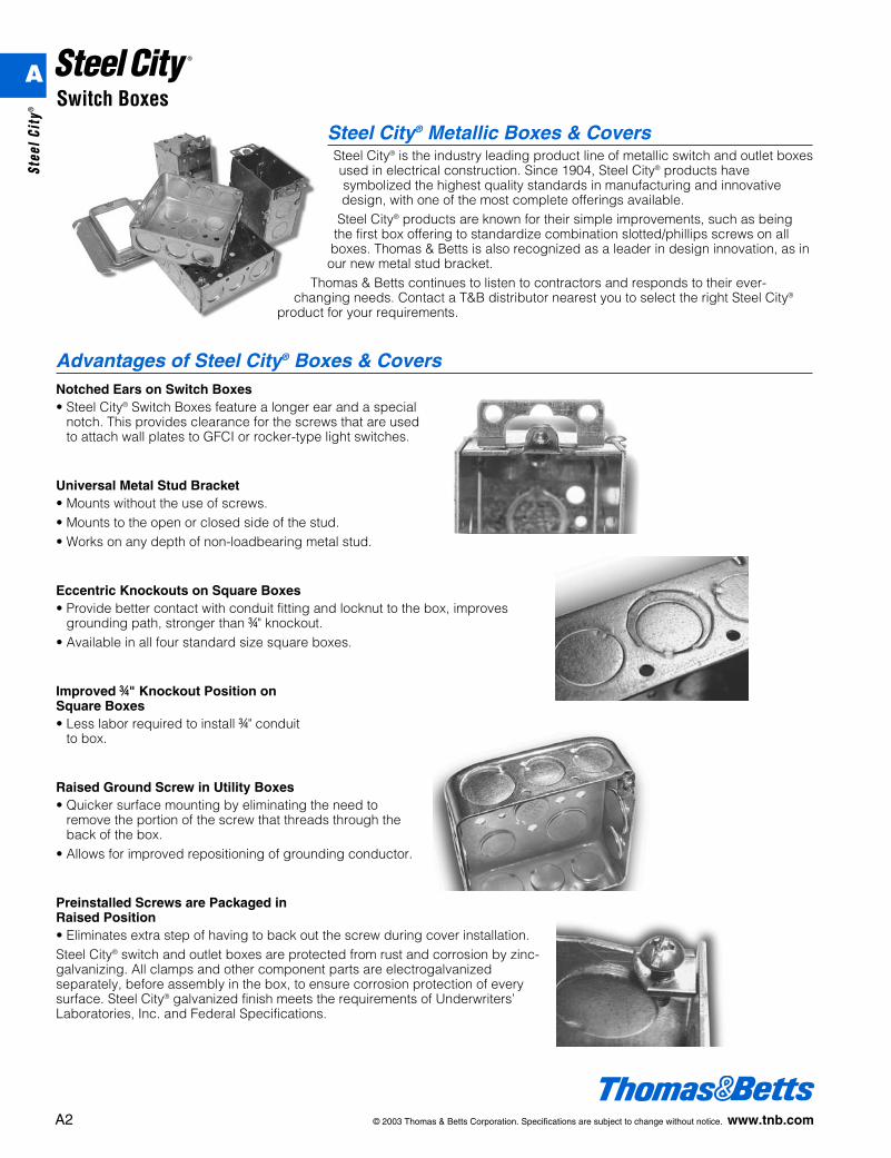
Advantages of Steel City® Boxes & CoversNotched Ears on Switch Boxes• Steel City® Switch Boxes feature a longer ear and a special
notch. This provides clearance for the screws that are usedto attach wall plates to GFCI or rocker-type light switches.
Universal Metal Stud Bracket• Mounts without the use of screws.• Mounts to the open or closed side of the stud.• Works on any depth of non-loadbearing metal stud.
Eccentric Knockouts on Square Boxes• Provide better contact with conduit fitting and locknut to the box, improves
grounding path, stronger than f" knockout.• Available in all four standard size square boxes.
Improved f" Knockout Position on Square Boxes• Less labor required to install f" conduit
to box.
Raised Ground Screw in Utility Boxes• Quicker surface mounting by eliminating the need to
remove the portion of the screw that threads through theback of the box.
• Allows for improved repositioning of grounding conductor.
Preinstalled Screws are Packaged in Raised Position• Eliminates extra step of having to back out the screw during cover installation.Steel City® switch and outlet boxes are protected from rust and corrosion by zinc-galvanizing. All clamps and other component parts are electrogalvanizedseparately, before assembly in the box, to ensure corrosion protection of everysurface. Steel City® galvanized finish meets the requirements of Underwriters’Laboratories, Inc. and Federal Specifications.
A
Stee
l Cit
y®
© 2003 Thomas & Betts Corporation. Specifications are subject to change without notice. www.tnb.com A3
Switch Boxes
N.E.C. ReferenceArticle 314 of the National Electric Code covers theinstallation and use of boxes. The article includes tablereferences that guide the electrician in the selection of theproper box size necessary to safely accommodate electricalservice requirements. The box capacity table shown on page4 is reproduced in part from the N.E.C. as a quick referenceand guide. The N.E.C. should be consulted for completedetails.
Article 314 – Boxes and Fittings314.16. Number of Conductors in Outlet, Device, andJunction Boxes, and Conduit Bodies.Boxes shall be of sufficient size to provide free space for allconductors enclosed in the box.The provisions of this section shall not apply to terminalhousings supplied with motors. (See Section 430.12.)Boxes and conduit bodies containing conductors, size No. 4or larger, shall also comply with the provisions of Section314.28.
(a) Standard Boxes.The maximum number of conductors permitted in standardboxes are listed in Table 314.16(A) reproduced in part onpage 4. See Article 314.28(A) through (D) where boxes orconduit bodies are used as junction or pull boxes.(1) Table 314.16(A) shall apply where no fittings or devices,such as fixture studs, cable clamps, hickeys, switches, orreceptacles, are contained in the box and where nogrounding conductors are part of the wiring within the box.Where one or more of these types of fittings, such as fixturestuds, cable clamps, or hickeys are contained in the box, thenumber of conductors shown in the table must be reducedby one for each type of fitting; an additional deduction of oneconductor must be made for each strap containing one ormore devices; and a further deduction of one conductor shallbe made for one or more grounding conductors entering thebox. Where a second set of equipment groundingconductors, as permitted by Section 250.146(D), ExceptionNo. 4, is present in the box, then an additional deduction ofone conductor must be made. A conductor running throughthe box is counted as one conductor, and each conductororiginating outside of the box and terminating inside the boxis counted as one conductor. Conductors, no part of whichleaves the box, shall not be counted. The volume of a wiringenclosure (box) shall be the total volume of the assembledsections, and, where used, the space provided by plaster
rings, domed covers, extension rings, etc., that are markedwith their volume in cubic inches, or are made from boxesthe dimensions of which are listed in Table 314.16(A).(2) For combinations of conductor sizes shown in Table314.16(A), the maximum number of conductors permitted iscomputed using the volume per conductor listed in Table314.16(B) with the deductions provided for in Section314.16(A)(1) and these volume deductions shall be basedon the largest conductor entering the box. The maximumnumber and size of conductors listed in Table 314.16(A)must not be exceeded.
(b) Other Boxes.Boxes 100 cubic inches or less, other than those describedin Table 314.16(A), conduit bodies having provisions formore than two conduit entries and nonmetallic boxes shallbe durably and legibly marked by the manufacturer with theircubic inch capacity. The maximum number of conductorspermitted shall be computed using the volume perconductor listed in Table 314.16(A), with the deductionsprovided for in Section 314.16(A)(1), and these volumedeductions shall be based on the largest conductor enteringthe box. Boxes described in Table 314.16(A) that have alarger cubic inch capacity than is designated in the tableshall be permitted to have their cubic inch capacity markedas required by this section and the maximum number ofconductors permitted shall be computed using the volumeper conductor listed in Table 314.16(B).
(c) Conduit Bodies.Conduit bodies enclosing No. 6 conductors or smaller shallhave a cross-sectional area not less than twice the cross-sectional area of the largest conduit to which it is attached.The maximum number of conductors permitted shall be themaximum number permitted by Table I, Chapter 9, for theconduit to which it is attached.Conduit bodies having provisions for less than three conduitentries shall not contain splices, taps, or devices unless theycomply with the provisions of Section 314.16(B) and aresupported in a rigid and secure manner.
A
Steel City®
A4 © 2003 Thomas & Betts Corporation. Specifications are subject to change without notice. www.tnb.com
Switch Boxes
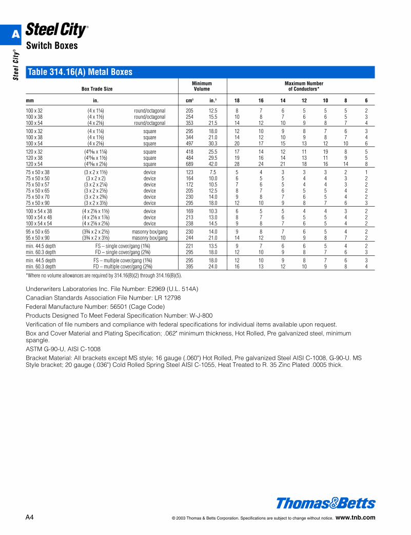
Table 314.16(A) Metal BoxesMinimum Maximum Number
Box Trade Size Volume of Conductors*
mm in. cm3 in.3 18 16 14 12 10 8 6
100 x 32 (4 x 1b) round/octagonal 205 12.5 8 7 6 5 5 5 2100 x 38 (4 x 1d) round/octagonal 254 15.5 10 8 7 6 6 5 3100 x 54 (4 x 2a) round/octagonal 353 21.5 14 12 10 9 8 7 4100 x 32 (4 x 1b) square 295 18.0 12 10 9 8 7 6 3100 x 38 (4 x 1d) square 344 21.0 14 12 10 9 8 7 4100 x 54 (4 x 2a) square 497 30.3 20 17 15 13 12 10 6120 x 32 (4L x 1b) square 418 25.5 17 14 12 11 19 8 5120 x 38 (4L x 1d) square 484 29.5 19 16 14 13 11 9 5120 x 54 (4L x 2a) square 689 42.0 28 24 21 18 16 14 875 x 50 x 38 (3 x 2 x 1d) device 123 7.5 5 4 3 3 3 2 175 x 50 x 50 (3 x 2 x 2) device 164 10.0 6 5 5 4 4 3 275 x 50 x 57 (3 x 2 x 2b) device 172 10.5 7 6 5 4 4 3 275 x 50 x 65 (3 x 2 x 2d) device 205 12.5 8 7 6 5 5 4 275 x 50 x 70 (3 x 2 x 2f) device 230 14.0 9 8 7 6 5 4 275 x 50 x 90 (3 x 2 x 3d) device 295 18.0 12 10 9 8 7 6 3100 x 54 x 38 (4 x 2a x 1d) device 169 10.3 6 5 5 4 4 3 2100 x 54 x 48 (4 x 2a x 1g) device 213 13.0 8 7 6 5 5 4 2100 x 54 x 54 (4 x 2a x 2a) device 238 14.5 9 8 7 6 5 4 295 x 50 x 65 (3f x 2 x 2d) masonry box/gang 230 14.0 9 8 7 6 5 4 295 x 50 x 90 (3f x 2 x 3d) masonry box/gang 244 21.0 14 12 10 9 8 7 2min. 44.5 depth FS – single cover/gang (1f) 221 13.5 9 7 6 6 5 4 2min. 60.3 depth FD – single cover/gang (2c) 295 18.0 12 10 9 8 7 6 3min. 44.5 depth FS – multiple cover/gang (1f) 295 18.0 12 10 9 8 7 6 3min. 60.3 depth FD – multiple cover/gang (2c) 395 24.0 16 13 12 10 9 8 4
*Where no volume allowances are required by 314.16(B)(2) through 314.16(B)(5).
Underwriters Laboratories Inc. File Number: E2969 (U.L. 514A)Canadian Standards Association File Number: LR 12798Federal Manufacture Number: 56501 (Cage Code)Products Designed To Meet Federal Specification Number: W-J-800Verification of file numbers and compliance with federal specifications for individual items available upon request.Box and Cover Material and Plating Specification; .062" minimum thickness, Hot Rolled, Pre galvanized steel, minimumspangle.ASTM G-90-U, AISI C-1008Bracket Material: All brackets except MS style; 16 gauge (.060") Hot Rolled, Pre galvanized Steel AISI C-1008, G-90-U. MSStyle bracket; 20 gauge (.036") Cold Rolled Spring Steel AISI C-1055, Heat Treated to R. 35 Zinc Plated .0005 thick.
A
Stee
l Cit
y®
© 2003 Thomas & Betts Corporation. Specifications are subject to change without notice. www.tnb.com A5
Switch Boxes
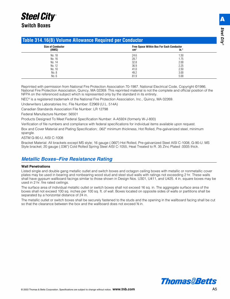
Table 314.16(B) Volume Allowance Required per ConductorSize of Conductor Free Space Within Box For Each Conductor
(AWG) cm3 in.3
No. 18 24.6 1.50No. 16 28.7 1.75No. 14 32.8 2.00No. 12 36.9 2.25No. 10 41.0 2.50No. 8 49.2 3.00No. 6 81.9 5.00
Reprinted with permission from National Fire Protection Association 70-1987. National Electrical Code, Copyright ©1986,National Fire Protection Association, Quincy, MA 02269. This reprinted material is not the complete and official position of theNFPA on the referenced subject which is represented only by the standard in its entirety.NEC® is a registered trademark of the National Fire Protection Association, Inc., Quincy, MA 02269.Underwriters Laboratories Inc. File Number: E2969 (U.L. 514A)Canadian Standards Association File Number: LR 12798Federal Manufacture Number: 56501Products Designed To Meet Federal Specification Number: A-A5924 (formerly W-J-800)Verification of file numbers and compliance with federal specifications for individual items available upon request.Box and Cover Material and Plating Specification; .062" minimum thickness, Hot Rolled, Pre-galvanized steel, minimumspangle.ASTM G-90-U, AISI C-1008Bracket Material: All brackets except MS style; 16 gauge (.060") Hot Rolled, Pre-galvanized Steel AISI C-1008, G-90-U. MSStyle bracket; 20 gauge (.036") Cold Rolled Spring Steel AISI C-1055, Heat Treated to R. 35 Zinc Plated .0005 thick.
Metallic Boxes–Fire Resistance RatingWall PenetrationsListed single and double gang metallic outlet and switch boxes and octagon ceiling boxes with metallic or nonmetallic coverplates may be used in bearing and nonbearing wood stud and steel stud walls with ratings not exceeding 2 hr. These wallsshall have gypsum wallboard facings similar to those shown in Design Nos. U301, U411, and U425. 4 in. square boxes may beused in 2 hr. fire rated ceilings.The surface area of individual metallic outlet or switch boxes shall not exceed 16 sq. in. The aggregate surface area of theboxes shall not exceed 100 sq. inches per 100 sq. ft. of wall. Boxes located on opposite sides of walls or partitions shall beseparated by a horizontal distance of 24 in.The metallic outlet or switch boxes shall be securely fastened to the studs and the opening in the wallboard facing shall be cutso that the clearance between the box and the wallboard does not exceed a in.
A
Steel City®
A6 © 2003 Thomas & Betts Corporation. Specifications are subject to change without notice. www.tnb.com
Switch Boxes
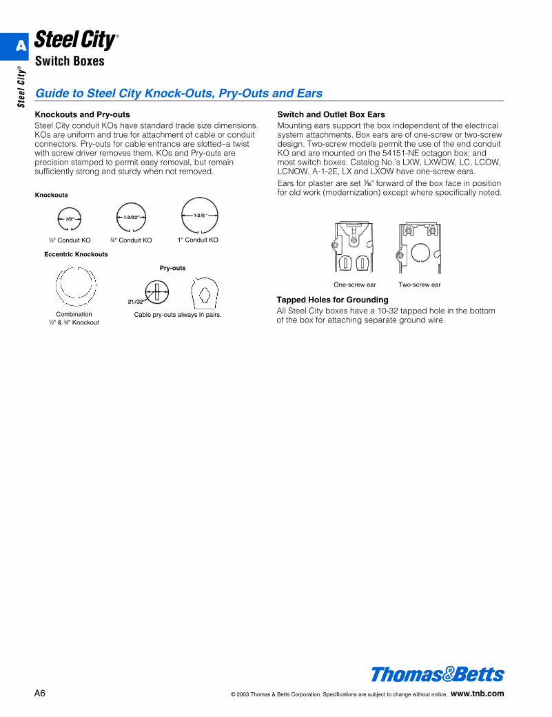
Guide to Steel City Knock-Outs, Pry-Outs and Ears
Two-screw earOne-screw ear
Cable pry-outs always in pairs.
d" Conduit KO f" Conduit KO 1" Conduit KO
Combinationd" & f" Knockout
Knockouts
Pry-outs
Eccentric Knockouts
Tapped Holes for GroundingAll Steel City boxes have a 10-32 tapped hole in the bottomof the box for attaching separate ground wire.
Knockouts and Pry-outsSteel City conduit KOs have standard trade size dimensions.KOs are uniform and true for attachment of cable or conduitconnectors. Pry-outs for cable entrance are slotted–a twistwith screw driver removes them. KOs and Pry-outs areprecision stamped to permit easy removal, but remainsufficiently strong and sturdy when not removed.
Switch and Outlet Box EarsMounting ears support the box independent of the electricalsystem attachments. Box ears are of one-screw or two-screwdesign. Two-screw models permit the use of the end conduitKO and are mounted on the 54151-NE octagon box; andmost switch boxes. Catalog No.’s LXW, LXWOW, LC, LCOW,LCNOW, A-1-2E, LX and LXOW have one-screw ears.Ears for plaster are set h" forward of the box face in positionfor old work (modernization) except where specifically noted.
A
Stee
l Cit
y®
© 2003 Thomas & Betts Corporation. Specifications are subject to change without notice. www.tnb.com A7
Switch Boxes
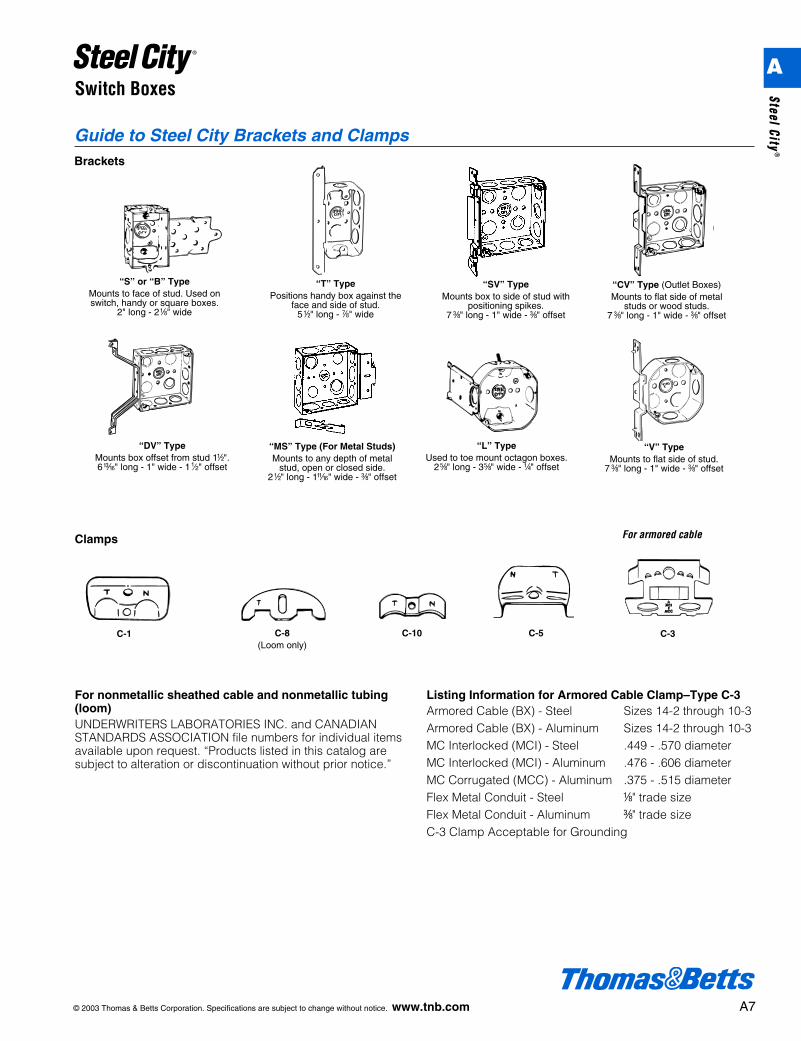
Guide to Steel City Brackets and ClampsBrackets
“DV” TypeMounts box offset from stud 1d".6m" long - 1" wide - 11⁄2" offset
“MS” Type (For Metal Studs)Mounts to any depth of metal
stud, open or closed side.2d" long - 1L" wide - c" offset
“S” or “B” TypeMounts to face of stud. Used onswitch, handy or square boxes.
2" long - 2a" wide
“T” TypePositions handy box against the
face and side of stud. 5d" long - g" wide
“SV” TypeMounts box to side of stud with
positioning spikes. 7 c" long - 1" wide - c" offset
“CV” Type (Outlet Boxes)Mounts to flat side of metal
studs or wood studs. 7 c" long - 1" wide - c" offset
C-5C-1 C-8(Loom only)
C-10 C-3
“L” TypeUsed to toe mount octagon boxes.
2e" long - 3e" wide - b" offset
“V” TypeMounts to flat side of stud.
7 c" long - 1" wide - c" offset
For armored cableClamps
For nonmetallic sheathed cable and nonmetallic tubing(loom)UNDERWRITERS LABORATORIES INC. and CANADIANSTANDARDS ASSOCIATION file numbers for individual itemsavailable upon request. “Products listed in this catalog aresubject to alteration or discontinuation without prior notice.”
Listing Information for Armored Cable Clamp–Type C-3Armored Cable (BX) - Steel Sizes 14-2 through 10-3Armored Cable (BX) - Aluminum Sizes 14-2 through 10-3MC Interlocked (MCI) - Steel .449 - .570 diameterMC Interlocked (MCI) - Aluminum .476 - .606 diameterMC Corrugated (MCC) - Aluminum .375 - .515 diameterFlex Metal Conduit - Steel a" trade sizeFlex Metal Conduit - Aluminum c" trade sizeC-3 Clamp Acceptable for Grounding
A
Steel City®
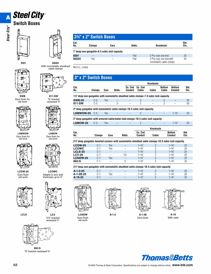
3" x 2" Switch BoxesKnockouts
Cat. Ea. End Ea. End Bottom Bottom Std.No. Clamps Ears Brkts. Conduit Cable Cable Cable Conduit Ctn.
1d" deep non-gangable–with nonmetallic sheathed cable clamps–7.5 cubic inch capacity
SWB-25 C-5 Yes – – 2 – 2 – 25811-SW C-5 – S – 2 – 2 – 50
2" deep gangable–with nonmetallic cable clamps–10.5 cubic inch capacity
LXMWOW-25 C-5 Yes – – 2 – – 1–d" 25
2" deep gangable–with armored cable/metal clad clamps–10.5 cubic inch capacity
LXMOW-25 C-3 Yes – – 2 – – 1–d" 25
KnockoutsCat. Ea. End Bottom Std.No. Clamps Ears Brkts. Conduit Cable Conduit Ctn.
2b" deep gangable–beveled corners–with nonmetallic sheathed cable clamps–10.5 cubic inch capacity
LCOW-25 C-1 Yes – 1–d" 2 1–d" 25LCOWC C-1 Yes – 1–d" 2 1–d" 25LCLE-25 C-1 – – 1–d" 2 1–d" 25LCV-25 C-1 – CV 1–d" 2 1–d" 25LCNOW-25 C-1 Yes – 1–d" 2 1–d" 25802-S C-1 – S 1–d" 2 1–d" 25
2b" deep non-gangable–with nonmetallic sheathed cable clamps–10.5 cubic inch capacity
A-1-2-25 C-1 – – 1–d" 2 1–d" 25A-1-2E-25 C-1 Yes – 1–d" 2 1–d" 25A-16-25 C-1 – – 1–d" 2 1–d" 25
A8 © 2003 Thomas & Betts Corporation. Specifications are subject to change without notice. www.tnb.com
Switch Boxes
LXMWOWEars flush for
old work
LXMOWEars flush for
old work
3f" x 2" Switch BoxesCat. Std.No. Clamps Ears Brkts. Knockouts Ctn.
1" deep non-gangable–6.5 cubic inch capacity
SSV – – Flat 2 Pry-outs one end 25SSQV Yes – Flat 2 Pry-outs one end with 25
nonmetallic cable clamps
Not U.L. ListedSSV SSQV
With nonmetallic sheathedcable clamps
SWBEars flush for
old work
811-SW“S” bracket recessed e"
LCOW-25Ears flushold work
LCLE LCV“CV” bracketrecessed f"
LCNOWEars flushold work
A-1-2 A-1-2EEars flush
A-16With nails
LCOWCAdapts to any wallthickness up to f"
802-S“S” bracket recessed e"
A
Stee
l Cit
y®
© 2003 Thomas & Betts Corporation. Specifications are subject to change without notice. www.tnb.com A9
Switch Boxes
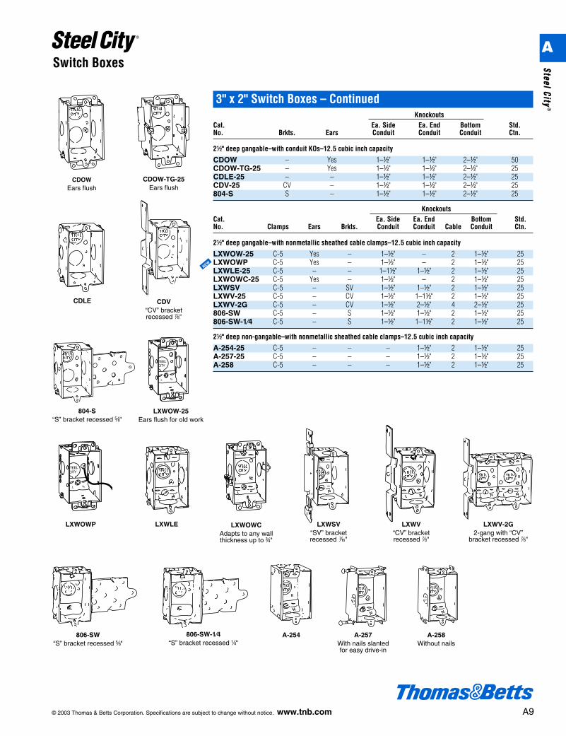
3" x 2" Switch Boxes – ContinuedKnockouts
Cat. Ea. Side Ea. End Bottom Std.No. Brkts. Ears Conduit Conduit Conduit Ctn.
2d" deep gangable–with conduit KOs–12.5 cubic inch capacity
CDOW – Yes 1–d" 1–d" 2–d" 50CDOW-TG-25 – Yes 1–d" 1–d" 2–d" 25CDLE-25 – – 1–d" 1–d" 2–d" 25CDV-25 CV – 1–d" 1–d" 2–d" 25804-S S – 1–d" 1–d" 2–d" 25
KnockoutsCat. Ea. Side Ea. End Bottom Std.No. Clamps Ears Brkts. Conduit Conduit Cable Conduit Ctn.
2d" deep gangable–with nonmetallic sheathed cable clamps–12.5 cubic inch capacity
LXWOW-25 C-5 Yes – 1–d" – 2 1–d" 25LXWOWP C-5 Yes – 1–d" – 2 1–d" 25LXWLE-25 C-5 – – 1–1d" 1–d" 2 1–d" 25LXWOWC-25 C-5 Yes – 1–d" – 2 1–d" 25LXWSV C-5 – SV 1–d" 1–d" 2 1–d" 25LXWV-25 C-5 – CV 1–d" 1–1d" 2 1–d" 25LXWV-2G C-5 – CV 1–d" 2–d" 4 2–d" 25806-SW C-5 – S 1–d" 1–d" 2 1–d" 25806-SW-1⁄4 C-5 – S 1–d" 1–1d" 2 1–d" 25
2d" deep non-gangable–with nonmetallic sheathed cable clamps–12.5 cubic inch capacity
A-254-25 C-5 – – – 1–d" 2 1–d" 25A-257-25 C-5 – – – 1–d" 2 1–d" 25A-258 C-5 – – – 1–d" 2 1–d" 25
CDOWEars flush
CDOW-TG-25Ears flush
CDLE CDV“CV” bracketrecessed g"
804-S“S” bracket recessed e"
806-SW“S” bracket recessed e"
LXWV“CV” bracketrecessed g"
LXWV-2G2-gang with “CV”
bracket recessed g"
806-SW-1⁄4“S” bracket recessed b"
LXWOW-25Ears flush for old work
LXWLE LXWOWCAdapts to any wallthickness up to f"
LXWSV“SV” bracketrecessed k"
A-254 A-257With nails slantedfor easy drive-in
A-258Without nails
LXWOWP
NEW
A
Steel City®
A10 © 2003 Thomas & Betts Corporation. Specifications are subject to change without notice. www.tnb.com
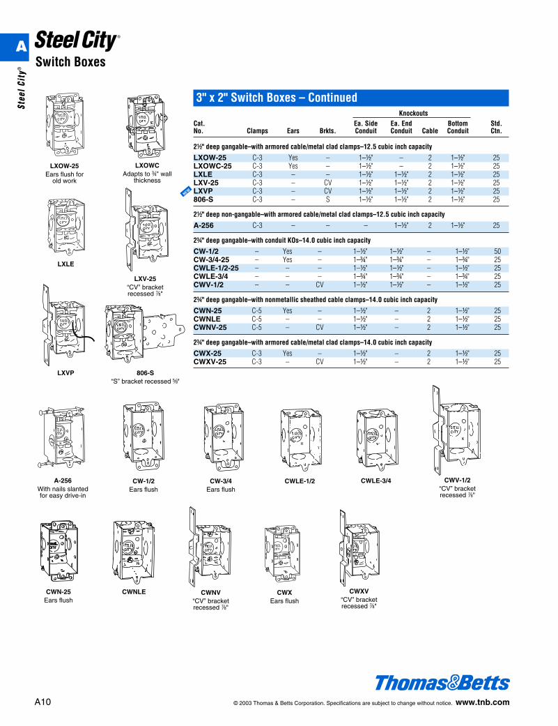
Switch Boxes
3" x 2" Switch Boxes – ContinuedKnockouts
Cat. Ea. Side Ea. End Bottom Std.No. Clamps Ears Brkts. Conduit Conduit Cable Conduit Ctn.
2d" deep gangable–with armored cable/metal clad clamps–12.5 cubic inch capacity
LXOW-25 C-3 Yes – 1–d" – 2 1–d" 25LXOWC-25 C-3 Yes – 1–d" – 2 1–d" 25LXLE C-3 – – 1–d" 1–d" 2 1–d" 25LXV-25 C-3 – CV 1–d" 1–d" 2 1–d" 25LXVP C-3 – CV 1–d" 1–d" 2 1–d" 25806-S C-3 – S 1–d" 1–d" 2 1–d" 25
2d" deep non-gangable–with armored cable/metal clad clamps–12.5 cubic inch capacity
A-256 C-3 – – – 1–d" 2 1–d" 25
2f" deep gangable–with conduit KOs–14.0 cubic inch capacity
CW-1/2 – Yes – 1–d" 1–d" – 1–d" 50CW-3/4-25 – Yes – 1–f" 1–f" – 1–f" 25CWLE-1/2-25 – – – 1–d" 1–d" – 1–d" 25CWLE-3/4 – – – 1–f" 1–f" – 1–f" 25CWV-1/2 – – CV 1–d" 1–d" – 1–d" 25
2f" deep gangable–with nonmetallic sheathed cable clamps–14.0 cubic inch capacity
CWN-25 C-5 Yes – 1–d" – 2 1–d" 25CWNLE C-5 – – 1–d" – 2 1–d" 25CWNV-25 C-5 – CV 1–d" – 2 1–d" 25
2f" deep gangable–with armored cable/metal clad clamps–14.0 cubic inch capacity
CWX-25 C-3 Yes – 1–d" – 2 1–d" 25CWXV-25 C-3 – CV 1–d" – 2 1–d" 25
LXOWCAdapts to f" wall
thickness
LXOW-25Ears flush for
old work
LXLE
LXV-25“CV” bracketrecessed g"
806-S“S” bracket recessed e"
A-256With nails slantedfor easy drive-in
LXVP
NEW
CWN-25Ears flush
CW-1/2Ears flush
CW-3/4Ears flush
CWLE-1/2 CWLE-3/4
CWXEars flush
CWXV“CV” bracketrecessed g"
CWNLE CWNV“CV” bracketrecessed g"
CWV-1/2“CV” bracketrecessed g"
A
Stee
l Cit
y®
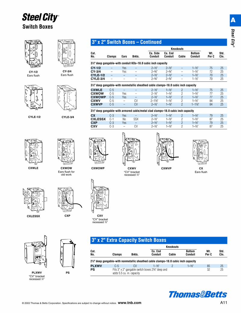
CXV“CV” bracketrecessed g"
CXWV“CV” bracketrecessed g"
CXEars flush
CXWLE CXWOWEars flush for
old work
CYLE-1/2 CYLE-3/4
3" x 2" Switch Boxes – ContinuedKnockouts
Cat. Ea. Side Ea. End Bottom Wt. Std.No. Clamps Ears Brkts. Conduit Conduit Cable Conduit Per C Ctn.
3d" deep gangable–with conduit KOs–18.0 cubic inch capacity
CY-1/2 – Yes – 2–d" 2–d" – 1–d" 75 25CY-3/4 – Yes – 2–f" 2–f" – 1–d" 72 25CYLE-1/2 – – – 2–d" 2–d" – 1–d" 70 25CYLE-3/4 – – – 2–f" 2–f" – 1–d" 70 25
3d" deep gangable–with nonmetallic sheathed cable clamps–18.0 cubic inch capacity
CXWLE C-5 – – 2–d" 1–d" 2 1–d" 75 25CXWOW C-5 Yes – 2–d" 1–d" 2 1–d" 77 25CXWOWP C-5 Yes – 2–d" 1–d" 2 1–d" 77 25CXWV C-5 – CV 2–1d" 1–d" 2 1–d" 84 25CXWVP C-5 – CV 2–d" 1–d" 2 1–1d" 84 25
3d" deep gangable–with armored cable/metal clad clamps–18.0 cubic inch capacity
CX C-3 Yes – 2–d" 1–d" 2 1–d" 79 25CXLESSX C-1 No SSX 2–d" 1–d" 2 1–d" 87 25CXP C-3 Yes – 2–d" 1–d" 2 1–d" 79 25CXV C-3 – CV 2–d" 1–d" 2 1–d" 87 25
CY-1/2Ears flush
CY-3/4Ears flush
CXWOWP CXWVP
CXP
3" x 2" Extra Capacity Switch BoxesKnockouts
Cat. Ea. End Bottom Wt. Std.No. Clamps Brkts. Conduit Cable Conduit Per C Ctn.
2d" deep gangable–with nonmetallic sheathed cable clamps–18.0 cubic inch capacity
PLXWV C-5 CV 1–d" 2 1–d" 85 25PS Fits 3" x 2" gangable switch boxes 2d" deep and 32 25
adds 5.5 cu. in. capacityPSPLXWV“CV” bracketrecessed g"
CXLESSX
© 2003 Thomas & Betts Corporation. Specifications are subject to change without notice. www.tnb.com A11
Switch BoxesA
Steel City®
A12 © 2003 Thomas & Betts Corporation. Specifications are subject to change without notice. www.tnb.com
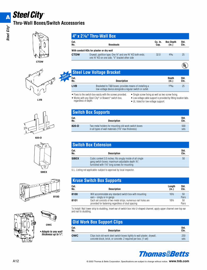
Thru-Wall Boxes/Switch Accessories
CTDW
820-D
SBEX
4" x 2h" Thru-Wall BoxCat. Cu. In. Box Depth Std.No. Knockouts Cap. (in.) Ctn.
With conduit KOs for plaster or dry wall
CTDW Drywall, partition type; One d" and one f" KO both ends; 32.0 4j 25one d" KO on one side, “V” bracket other side
Switch Box SupportsCat. Std.No. Description Ctn.
820-D Two metal holders for mounting old-work switch boxes 500in all types of wall materials (1d" max thickness) sets
Switch Box ExtensionCat. Std.No. Description Ctn.
SBEX Cubic content 3.5 inches; fits snugly inside of all single 50gang switch boxes; maximum adjustable depth g";furnished with 1b" long screws for mounting
U.L. Listing not applicable–subject to approval by local inspector.
Kruse Switch Box SupportsCat. Length Std.No. Description (in.) Ctn.
8100 Will accommodate any standard switch box with mounting 16d 50ears – singly or in gangs Pairs
8101 Each set consists of two metal strips; numerous nail holes are 18d 50provided for fastening regardless of stud spacing Pairs
To Install: Nail lower strip to studding, insert ear of switch box into U-shaped channel, apply upper channel over top earand nail to studding.
OWC
8100
• Adapts to any wallthickness up to 3⁄4".
Old Work Box Support ClipsCat. Std.No. Description Ctn.
OWC Clips lock old-work steel switch boxes tightly to wall plaster, drywall, 250concrete block, brick, or concrete. 2 required per box, (1 set) sets
LVB
Steel Low Voltage BracketCat. Depth Std.No. Description (in.) Ctn.
LVB Bracketed to T&B boxes; provides means of installing a 1A 25low-voltage device alongside a regular switch or outlet.
• Fixes to the switch box easily with the screws provided.• Works with any Steel City® or Bowers® switch box,
regardless of depth.
• Single screw fixing as well as two screw fixing.• Low voltage cable support is provided by fitting location tabs.• UL listed for low voltage support.
New
Product
®
A
Stee
l Cit
y®
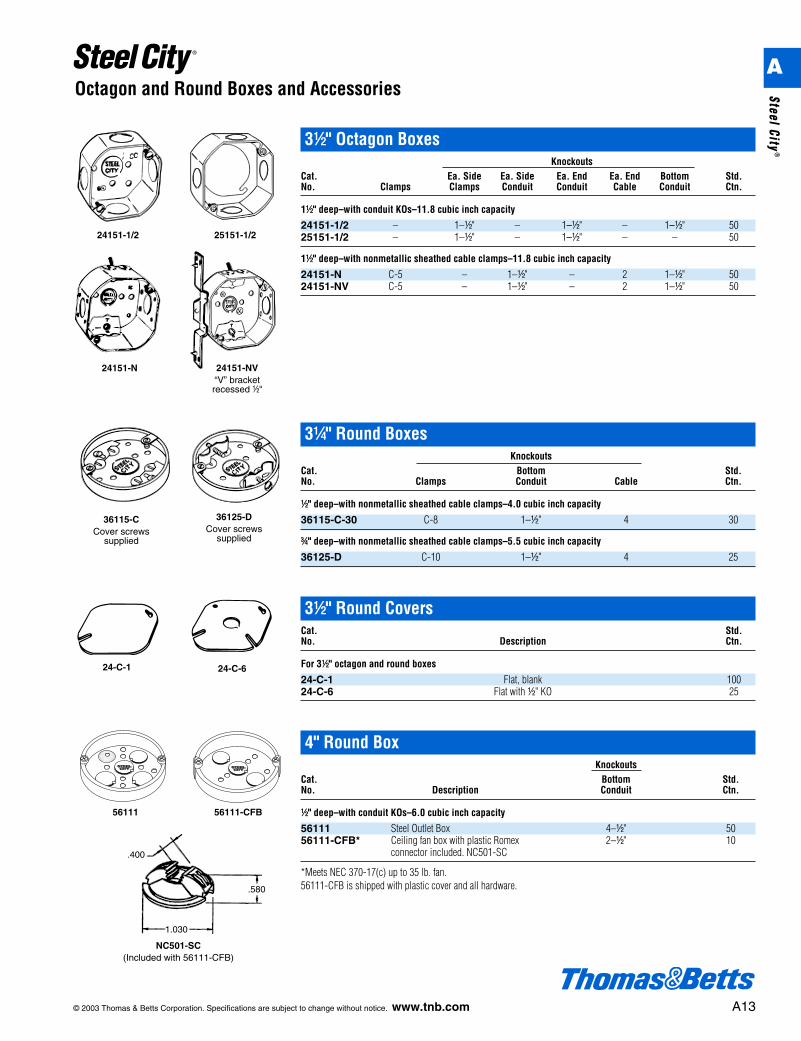
3b" Round BoxesKnockouts
Cat. Bottom Std.No. Clamps Conduit Cable Ctn.
d" deep–with nonmetallic sheathed cable clamps–4.0 cubic inch capacity
36115-C-30 C-8 1–d" 4 30
f" deep–with nonmetallic sheathed cable clamps–5.5 cubic inch capacity
36125-D C-10 1–d" 4 25
© 2003 Thomas & Betts Corporation. Specifications are subject to change without notice. www.tnb.com A13
Octagon and Round Boxes and Accessories
36115-CCover screws
supplied
36125-DCover screws
supplied
3d" Octagon BoxesKnockouts
Cat. Ea. Side Ea. Side Ea. End Ea. End Bottom Std.No. Clamps Clamps Conduit Conduit Cable Conduit Ctn.
1d" deep–with conduit KOs–11.8 cubic inch capacity
24151-1/2 – 1–d" – 1–d" – 1–d" 5025151-1/2 – 1–d" – 1–d" – – 50
1d" deep–with nonmetallic sheathed cable clamps–11.8 cubic inch capacity
24151-N C-5 – 1–d" – 2 1–d" 5024151-NV C-5 – 1–d" – 2 1–d" 50
24151-1/2 25151-1/2
24151-N 24151-NV“V” bracket recessed d"
3d" Round CoversCat. Std.No. Description Ctn.
For 3d" octagon and round boxes
24-C-1 Flat, blank 10024-C-6 Flat with d" KO 25
24-C-1 24-C-6
4" Round BoxKnockouts
Cat. Bottom Std.No. Description Conduit Ctn.
d" deep–with conduit KOs–6.0 cubic inch capacity
56111 Steel Outlet Box 4–d" 5056111-CFB* Ceiling fan box with plastic Romex 2–d" 10
connector included. NC501-SC
*Meets NEC 370-17(c) up to 35 lb. fan.56111-CFB is shipped with plastic cover and all hardware.
56111-CFB
.400
.580
1.030
NC501-SC(Included with 56111-CFB)
56111
A
Steel City®
A14 © 2003 Thomas & Betts Corporation. Specifications are subject to change without notice. www.tnb.com
Octagon Boxes
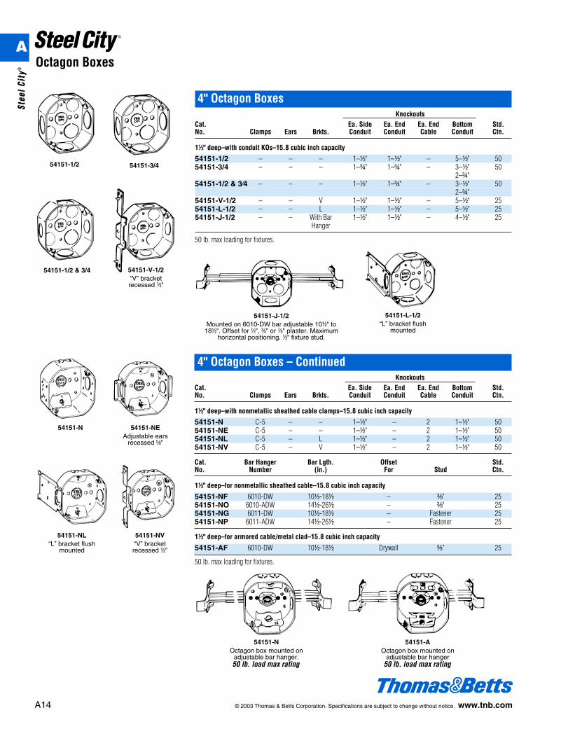
4" Octagon BoxesKnockouts
Cat. Ea. Side Ea. End Ea. End Bottom Std.No. Clamps Ears Brkts. Conduit Conduit Cable Conduit Ctn.
1d" deep–with conduit KOs–15.8 cubic inch capacity
54151-1/2 – – – 1–d" 1–d" – 5–d" 5054151-3/4 – – – 1–f" 1–f" – 3–d" 50
2–f"54151-1/2 & 3⁄4 – – – 1–d" 1–f" – 3–d" 50
2–f"54151-V-1/2 – – V 1–d" 1–d" – 5–d" 2554151-L-1/2 – – L 1–d" 1–d" – 5–d" 2554151-J-1/2 – – With Bar 1–d" 1–d" – 4–d" 25
Hanger
50 lb. max loading for fixtures.
54151-1/2 54151-3/4
54151-J-1/2Mounted on 6010-DW bar adjustable 10d" to
18d". Offset for d", f" or g" plaster. Maximumhorizontal positioning. d" fixture stud.
54151-L-1/2“L” bracket flush
mounted
54151-1/2 & 3/4 54151-V-1/2“V” bracket recessed d"
54151-AOctagon box mounted on
adjustable bar hanger50 lb. load max rating
4" Octagon Boxes – ContinuedKnockouts
Cat. Ea. Side Ea. End Ea. End Bottom Std.No. Clamps Ears Brkts. Conduit Conduit Cable Conduit Ctn.
1d" deep–with nonmetallic sheathed cable clamps–15.8 cubic inch capacity
54151-N C-5 – – 1–d" – 2 1–d" 5054151-NE C-5 – – 1–d" – 2 1–d" 5054151-NL C-5 – L 1–d" – 2 1–d" 5054151-NV C-5 – V 1–d" – 2 1–d" 50
Cat. Bar Hanger Bar Lgth. Offset Std.No. Number (in.) For Stud Ctn.
1d" deep–for nonmetallic sheathed cable–15.8 cubic inch capacity
54151-NF 6010-DW 10d-18d – c" 2554151-NO 6010-ADW 14d-26d – c" 2554151-NG 6011-DW 10d-18d – Fastener 2554151-NP 6011-ADW 14d-26d – Fastener 25
1d" deep–for armored cable/metal clad–15.8 cubic inch capacity
54151-AF 6010-DW 10d-18d Drywall c" 25
50 lb. max loading for fixtures.
54151-NL“L” bracket flush
mounted
54151-NV“V” bracketrecessed d"
54151-N 54151-NEAdjustable ears
recessed e"
54151-NOctagon box mounted on
adjustable bar hanger.50 lb. load max rating
A
Stee
l Cit
y®
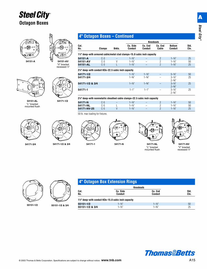
4" Octagon Boxes – ContinuedKnockouts
Cat. Ea. Side Ea. End Ea. End Bottom Std.No. Clamps Brkts. Conduit Conduit Cable Conduit Ctn.
1d" deep–with armored cable/metal clad clamps–15.8 cubic inch capacity
54151-A C-3 – 1–d" – 2 1–d" 2554151-AV C-3 V 1–d" – 2 1–d" 5054151-AL C-3 L 1–d" – 2 1–d" 25
2a" deep–with conduit KOs–22.5 cubic inch capacity
54171-1/2 1–d" 1–d" – 5–d" 5054171-3/4 1–f" 1–f" – 3–d" 25
2–f"54171-1/2 & 3/4 1–d" 1–f" – 3–d" 25
2–f"54171-1 1–1" 1–1" – 3–d" 25
2–f"
2a" deep–with nonmetallic sheathed cable clamps–22.5 cubic inch capacity
54171-N C-5 – 1–d" – 2 1–d" 5054171-NL C-5 L 1–d" – 2 1–d" 5054171-NV-25 C-5 V 1–d" – 2 1–d" 25
50 lb. max loading for fixtures.
© 2003 Thomas & Betts Corporation. Specifications are subject to change without notice. www.tnb.com A15
Octagon Boxes
54171-NV“V” bracketrecessed d"
54151-AL“L” bracket
mounted flush
54151-AV“V” bracketrecessed d"
54171-1/2
54171-3/4 54171-N 54171-NL“L” bracket
mounted flush
54151-A
54171-1/2 & 3/4 54171-1
55151-1/2 55151-1/2 & 3/4
4" Octagon Box Extension RingsKnockouts
Cat. Ea. Side Ea. End Std.No. Conduit Conduit Ctn.
1d" deep–with conduit KOs–15.8 cubic inch capacity
55151-1/2 1–d" 1–d" 5055151-1/2 & 3/4 1–d" 1–f" 25
A
Steel City®
A16 © 2003 Thomas & Betts Corporation. Specifications are subject to change without notice. www.tnb.com
Octagon Boxes
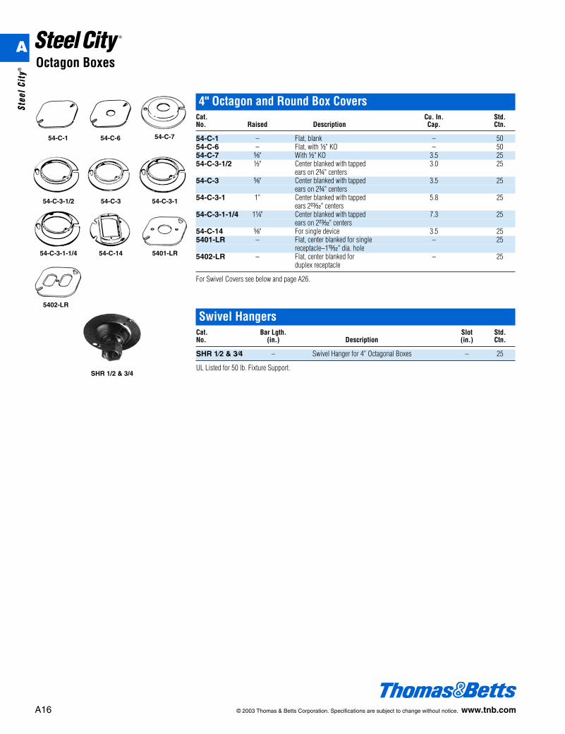
4" Octagon and Round Box CoversCat. Cu. In. Std.No. Raised Description Cap. Ctn.
54-C-1 – Flat, blank – 5054-C-6 – Flat, with d" KO – 5054-C-7 e" With d" KO 3.5 2554-C-3-1/2 d" Center blanked with tapped 3.0 25
ears on 2f" centers54-C-3 e" Center blanked with tapped 3.5 25
ears on 2f" centers54-C-3-1 1" Center blanked with tapped 5.8 25
ears 2z" centers54-C-3-1-1/4 1b" Center blanked with tapped 7.3 25
ears on 2z" centers54-C-14 e" For single device 3.5 255401-LR – Flat, center blanked for single – 25
receptacle–1u" dia. hole5402-LR – Flat, center blanked for – 25
duplex receptacle
For Swivel Covers see below and page A26.
54-C-1 54-C-6 54-C-7
54-C-3-1/2 54-C-3 54-C-3-1
54-C-3-1-1/4 54-C-14 5401-LR
5402-LR
Swivel HangersCat. Bar Lgth. Slot Std.No. (in.) Description (in.) Ctn.
SHR 1⁄2 & 3⁄4 – Swivel Hanger for 4” Octagonal Boxes – 25
UL Listed for 50 lb. Fixture Support.SHR 1/2 & 3/4
A
Stee
l Cit
y®
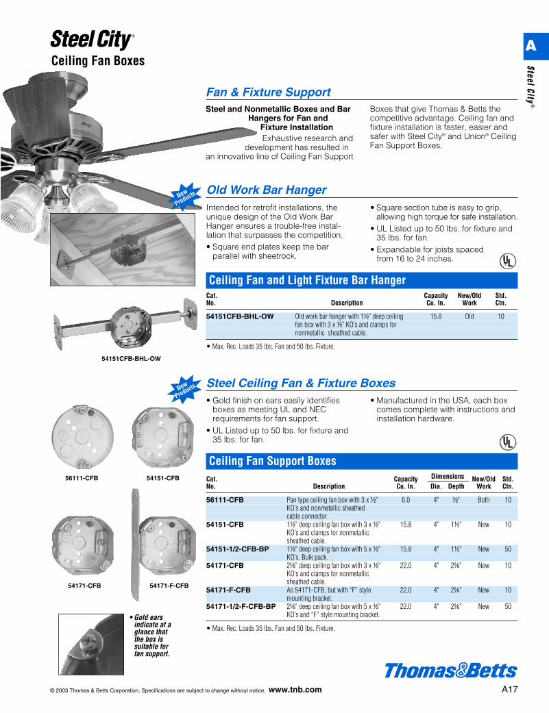
Ceiling Fan and Light Fixture Bar HangerCat. Capacity New/Old Std.No. Description Cu. In. Work Ctn.
54151CFB-BHL-OW Old work bar hanger with 1d" deep ceiling 15.8 Old 10fan box with 3 x d" KO’s and clamps for nonmetallic sheathed cable.
• Max. Rec. Loads 35 lbs. Fan and 50 lbs. Fixture.
54151CFB-BHL-OW
Old Work Bar HangerIntended for retrofit installations, theunique design of the Old Work BarHanger ensures a trouble-free instal-lation that surpasses the competition.• Square end plates keep the bar
parallel with sheetrock.
• Square section tube is easy to grip,allowing high torque for safe installation.
• UL Listed up to 50 lbs. for fixture and35 lbs. for fan.
• Expandable for joists spaced from 16 to 24 inches.
Steel Ceiling Fan & Fixture Boxes• Gold finish on ears easily identifies
boxes as meeting UL and NECrequirements for fan support.
• UL Listed up to 50 lbs. for fixture and35 lbs. for fan.
• Manufactured in the USA, each boxcomes complete with instructions andinstallation hardware.
• Gold earsindicate at aglance thatthe box issuitable forfan support.
®
56111-CFB 54151-CFB
54171-CFB 54171-F-CFB
Ceiling Fan Support BoxesCat. Capacity Dimensions New/Old Std.No. Description Cu. In. Dia. Depth Work Ctn.
56111-CFB Pan type ceiling fan box with 3 x d" 6.0 4" d" Both 10KO’s and nonmetallic sheathedcable connector
54151-CFB 1d" deep ceiling fan box with 3 x d" 15.8 4" 1d" New 10KO’s and clamps for nonmetallic sheathed cable.
54151-1/2-CFB-BP 1d" deep ceiling fan box with 5 x d" 15.8 4" 1d" New 50KO’s. Bulk pack.
54171-CFB 2a" deep ceiling fan box with 3 x d" 22.0 4" 2a" New 10KO’s and clamps for nonmetallic sheathed cable.
54171-F-CFB As 54171-CFB, but with “F” style 22.0 4" 2a" New 10mounting bracket.
54171-1/2-F-CFB-BP 2a" deep ceiling fan box with 5 x d" 22.0 4" 2a" New 50KO’s and “F” style mounting bracket.
• Max. Rec. Loads 35 lbs. Fan and 50 lbs. Fixture.
© 2003 Thomas & Betts Corporation. Specifications are subject to change without notice. www.tnb.com A17
®
Fan & Fixture SupportSteel and Nonmetallic Boxes and Bar
Hangers for Fan andFixture InstallationExhaustive research and
development has resulted inan innovative line of Ceiling Fan Support
Boxes that give Thomas & Betts thecompetitive advantage. Ceiling fan andfixture installation is faster, easier andsafer with Steel City® and Union® CeilingFan Support Boxes.
New
Products
Ceiling Fan Boxes
New
Products
A
Steel City®
A18 © 2003 Thomas & Betts Corporation. Specifications are subject to change without notice. www.tnb.com
Ceiling Fan Boxes
56111CFB-BHL
54151CFB-BHL
4070CFB-BHL CFB-BHL
4170-CFB
4170-3-CFB
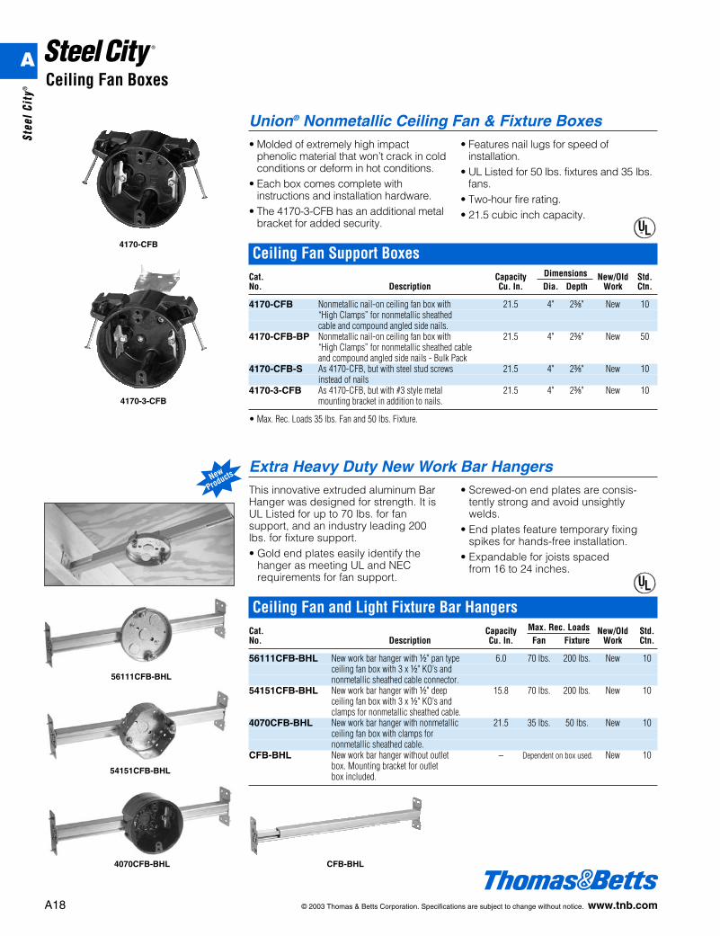
Ceiling Fan Support BoxesCat. Capacity Dimensions New/Old Std.No. Description Cu. In. Dia. Depth Work Ctn.
4170-CFB Nonmetallic nail-on ceiling fan box with 21.5 4" 2c" New 10“High Clamps” for nonmetallic sheathed cable and compound angled side nails.
4170-CFB-BP Nonmetallic nail-on ceiling fan box with 21.5 4" 2c" New 50“High Clamps” for nonmetallic sheathed cable and compound angled side nails - Bulk Pack
4170-CFB-S As 4170-CFB, but with steel stud screws 21.5 4" 2c" New 10instead of nails
4170-3-CFB As 4170-CFB, but with #3 style metal 21.5 4" 2c" New 10mounting bracket in addition to nails.
• Max. Rec. Loads 35 lbs. Fan and 50 lbs. Fixture.
Union® Nonmetallic Ceiling Fan & Fixture Boxes• Molded of extremely high impact
phenolic material that won’t crack in coldconditions or deform in hot conditions.
• Each box comes complete withinstructions and installation hardware.
• The 4170-3-CFB has an additional metalbracket for added security.
• Features nail lugs for speed ofinstallation.
• UL Listed for 50 lbs. fixtures and 35 lbs.fans.
• Two-hour fire rating.• 21.5 cubic inch capacity.
®
Ceiling Fan and Light Fixture Bar HangersCat. Capacity Max. Rec. Loads New/Old Std.No. Description Cu. In. Fan Fixture Work Ctn.
56111CFB-BHL New work bar hanger with d" pan type 6.0 70 lbs. 200 lbs. New 10ceiling fan box with 3 x d" KO’s and nonmetallic sheathed cable connector.
54151CFB-BHL New work bar hanger with d" deep 15.8 70 lbs. 200 lbs. New 10ceiling fan box with 3 x d" KO’s and clamps for nonmetallic sheathed cable.
4070CFB-BHL New work bar hanger with nonmetallic 21.5 35 lbs. 50 lbs. New 10ceiling fan box with clamps fornonmetallic sheathed cable.
CFB-BHL New work bar hanger without outlet – Dependent on box used. New 10box. Mounting bracket for outletbox included.
Extra Heavy Duty New Work Bar HangersThis innovative extruded aluminum BarHanger was designed for strength. It isUL Listed for up to 70 lbs. for fansupport, and an industry leading 200lbs. for fixture support.• Gold end plates easily identify the
hanger as meeting UL and NECrequirements for fan support.
• Screwed-on end plates are consis-tently strong and avoid unsightlywelds.
• End plates feature temporary fixingspikes for hands-free installation.
• Expandable for joists spaced from 16 to 24 inches.
®
New
Products
A
Stee
l Cit
y®
© 2003 Thomas & Betts Corporation. Specifications are subject to change without notice. www.tnb.com A19
Ceiling Fan Boxes
CFB-12
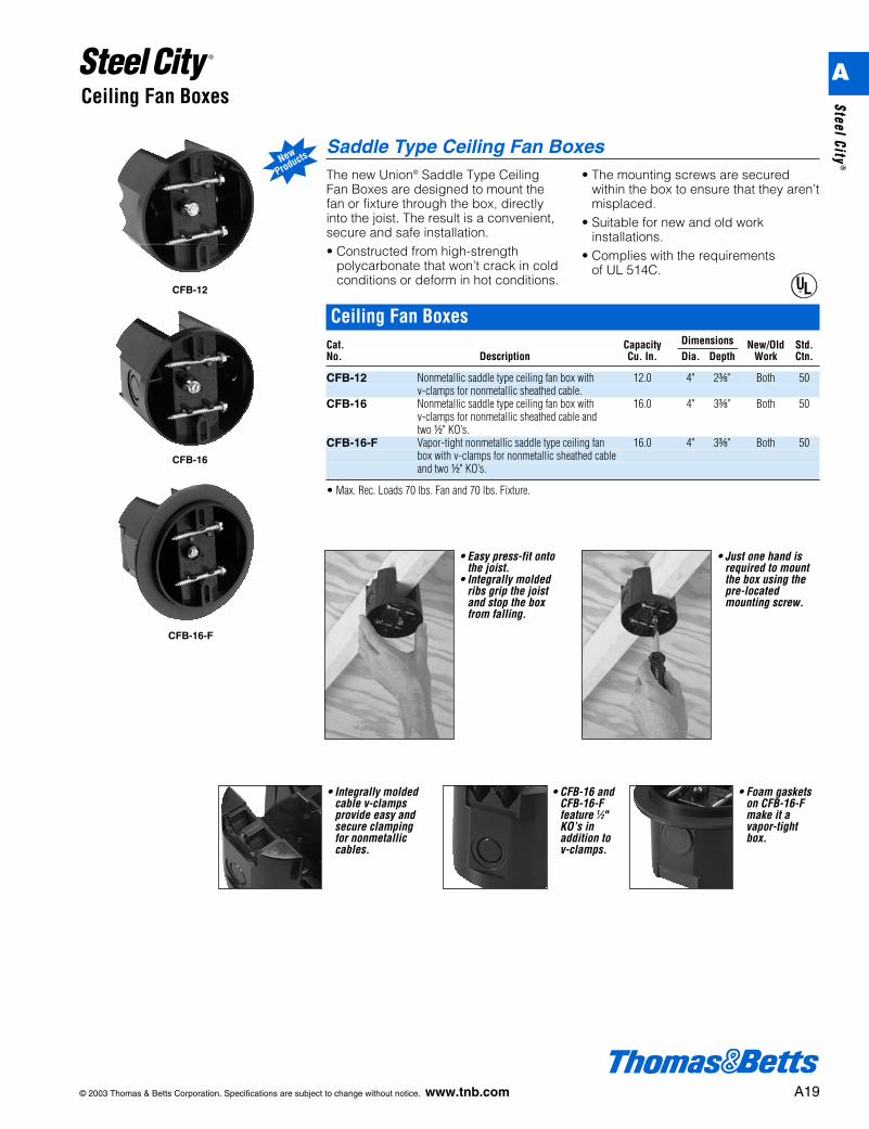
Ceiling Fan BoxesCat. Capacity Dimensions New/Old Std.No. Description Cu. In. Dia. Depth Work Ctn.
CFB-12 Nonmetallic saddle type ceiling fan box with 12.0 4" 2c" Both 50v-clamps for nonmetallic sheathed cable.
CFB-16 Nonmetallic saddle type ceiling fan box with 16.0 4" 3c" Both 50v-clamps for nonmetallic sheathed cable andtwo d" KO’s.
CFB-16-F Vapor-tight nonmetallic saddle type ceiling fan 16.0 4" 3c" Both 50box with v-clamps for nonmetallic sheathed cableand two d" KO’s.
• Max. Rec. Loads 70 lbs. Fan and 70 lbs. Fixture.
Saddle Type Ceiling Fan BoxesThe new Union® Saddle Type CeilingFan Boxes are designed to mount thefan or fixture through the box, directlyinto the joist. The result is a convenient,secure and safe installation.• Constructed from high-strength
polycarbonate that won’t crack in coldconditions or deform in hot conditions.
• The mounting screws are securedwithin the box to ensure that they aren’tmisplaced.
• Suitable for new and old workinstallations.
• Complies with the requirements of UL 514C.
®
New
Products
• Easy press-fit ontothe joist.
• Integrally moldedribs grip the joistand stop the boxfrom falling.
• Just one hand isrequired to mountthe box using thepre-locatedmounting screw.
• Integrally moldedcable v-clampsprovide easy andsecure clampingfor nonmetalliccables.
• CFB-16 andCFB-16-Ffeature 1⁄2"KO’s inaddition tov-clamps.
• Foam gasketson CFB-16-Fmake it avapor-tightbox.
CFB-16
CFB-16-F
A
Steel City®
52151-MS-1/2 & 3/4For use on 1e", 2d",
3e", 4", 6" metal studs
A20 © 2003 Thomas & Betts Corporation. Specifications are subject to change without notice. www.tnb.com
Square Boxes and Accessories
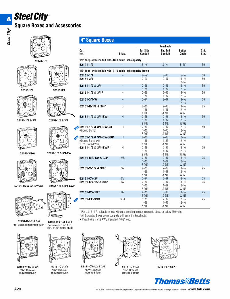
4" Square BoxesKnockouts
Cat. Ea. Side Ea. End Bottom Std.No. Brkts. Conduit Conduit Cable Ctn.
1b" deep–with conduit KOs–18.0 cubic inch capacity
52141-1/2 – 2–d" 3–d" 5–d" 50
1d" deep–with conduit KOs–21.0 cubic inch capacity drawn
52151-1/2 – 3–d" 3–d 5–d 5052151-3/4 – 2–f 2–f 3–d 50
2–f52151-1/2 & 3/4 – 2–d 2–d 3–d 50
1–f 1–f 2–f52151-1/2 & 3/4P – 2–d 2–d 3–d 50
1–f 1–f 2–f52151-3/4-W – 2–f 2–f 3–d 50
2–f52151-B-1/2 & 3/4* B 2–d 2–d 3–d 25
1–d 1–f 2–d& fE & fE & fE
52151-1/2 & 3/4-EW* H 2–d 2–d 3–d 501–d 1–d 2–d& fE & fE & fE
52151-1/2 & 3/4-EWGB H 2–d 2–d 2–d 50(Ground Bump) 1–d 1–d 2–d
& fE & fE & fE52151-1/2 & 3/4-EWGBP H 2–d 2–d 2–d 50(Ground Bump with 1–d 1–d 2–d10d" Ground Wire) & fE & fE & fE52151-1/2 & 3/4-EWP* H 2–d 2–d 3–d 50
1–d 1–d 2–d& fE & fE & fE
52151-MS-1/2 & 3/4* MS 2–d 2–d 3–d 251–d 1–f 2–d& fE & fE & fE
52151-V-1/2 & 3/4* SV 2–d 2–d 3–d 251–d 1–f 2–d& fE & fE & fE
52151-CV-3/4 CV 2–f 2–f 3–d 2552151-CV-1/2 & 3/4* CV 2–d 2–d 3–d 25
1–d 1–f 2–d& fE & fE & fE
52151-DV-1/2* DV 2–d 3–d 3–d 25& fE & fE & fE
52151-EF-SSX SSX 1–d 2–d 2–d 251–d 1–d 2–d& fE & fE & fE
* Per U.L. 514-A, suitable for use without a bonding jumper in circuits above or below 250 volts.* All Bracketed Boxes come complete with eccentric knockouts.• Pigtail wire is #12 AWG insulated, 10d" long.
52141-1/2
52151-1/2 & 3/4
52151-3/4-W
52151-1/2 52151-3/4
52151-1/2 & 3/4
52151-1/2 & 3/4-EW
52151-B-1/2 & 3/4“B” Bracket mounted flush
52151-DV-1/2“DV” Bracket
provides offset
52151-CV-3/4“CV” Bracket
mounted flush
52151-CV-1/2 & 3/4“CV” Bracket
mounted flush
52151-V-1/2 & 3/4“SV” Bracket
mounted flush
52151-1/2 & 3/4-EWGB 52151-1/2 & 3/4-EWP
52151-EF-SSX
NEW
NEW
NEW
A
Stee
l Cit
y®
4" Square Boxes – ContinuedKnockouts
Cat. Ea. Side Ea. End Bottom Std.No. Clamps Brkts. Conduit Cable Conduit Ctn.
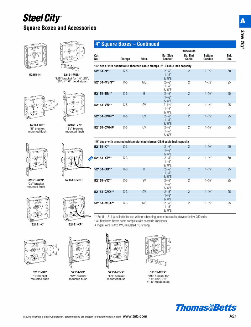
1d" deep–with nonmetallic sheathed cable clamps–21.0 cubic inch capacity
52151-N** C-5 – 2–d" 2 1–d" 501–d"& f"E
52151-MSN** C-5 MS 2–d" 2 1–d" 251–d"& f"E
52151-BN** C-5 B 2–d" 2 1–d" 251–d"& f"E
52151-VN** C-5 SV 2–1d" 2 1–d" 251–d"& f"E
52151-CVN** C-5 CV 2–d" 2 1–d" 251–d"& f"E
52151-CVNP C-5 CV 2–d" 2 1–d" 251–d"& f"E
1d" deep–with armored cable/metal clad clamps–21.0 cubic inch capacity
52151-X** C-3 – 2–d" 2 1–d" 501–d"& f"E
52151-XP** C-3 – 2–d" 2 1–d" 501–d"& f"E
52151-BX** C-3 B 2–d" 2 1–d" 251–d"& f"E
52151-VX** C-3 SV 2–d" 2 1–d" 251–d"& f"E
52151-CVX** C-3 CV 2–d" 2 1–d" 251–d"& f"E
52151-MSX** C-3 MS 2–d" 2 1–d" 251–d"& f"E
** Per U.L. 514-A, suitable for use without a bonding jumper in circuits above or below 250 volts.* All Bracketed Boxes come complete with eccentric knockouts.• Pigtail wire is #12 AWG insulated, 10d" long.
© 2003 Thomas & Betts Corporation. Specifications are subject to change without notice. www.tnb.com A21
Square Boxes and Accessories
52151-N* 52151-MSN*“MS” bracket for 1e", 2d",
3e", 4", 6" metal studs
52151-BN*“B” bracket
mounted flush
52151-CVN*“CV” bracket
mounted flush
52151-VN*“SV” bracket
mounted flush
52151-CVNP
52151-VX*“SV” bracket
mounted flush
52151-X*
52151-BX*“B” bracket
mounted flush
52151-MSX*“MS” bracket for1e", 2d", 3e",
4", 6" metal studs
52151-CVX*“CV” bracket
mounted flush
52151-XP*
A
Steel City®
NEW
4" Square Boxes – ContinuedKnockouts
Cat. Ea. Side Ea. End Bottom Std.No. Clamps Brkts. Conduit Cable Conduit Ctn.
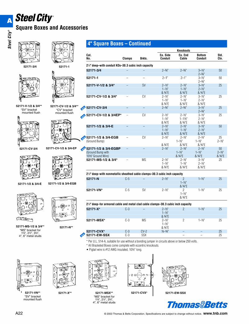
2a" deep–with conduit KOs–30.3 cubic inch capacity
52171-3/4 – – 2–f" 2–f" 3–d" 502–f"
52171-1 – – 2–1" 2–1" 3–d" 502–f"
52171-V-1/2 & 3/4* – SV 2–d" 2–d" 3–d" 251–d" 1–d" 2–d"& f"E & f"E & f"E
52171-CV-1/2 & 3/4* – CV 2–d" 2–d" 3–d" 251–d" 1–d" 2–d"& f"E & f"E & f"E
52171-CV-3/4 – – 2–f" 2–f" 3–d" 252–f"
52171-CV-1/2 & 3/4EP* – CV 2–d" 2–d" 3–d" 251–d" 1–1d" 2–d"& f"E & f"E & f"E
52171-1/2 & 3/4-E – – 2–d" 2–d" 3–d" 501–d" 1–d" 2–d"& f"E & f"E & f"E
52171-1/2 & 3/4-EGB – CV 2–d" 2–d" 2–d" 25(Ground Bump) 1–d" 1–d" 2–d"
& f"E & f"E & f"E52171-1/2 & 3/4-EGBP – – 2–d" 2–d" 2–d" 50(Ground Bump with 1–d" 1–d" 2–d"10d" Ground Wire) & f"E & f"E & f"E52171-MS-1/2 & 3/4* – MS 2–d" 2–d" 3–d" 25
1–d" 1–d" 2–d"& f"E & f"E & f"E
2a" deep–with nonmetallic sheathed cable clamps–30.3 cubic inch capacity
52171-N C-5 – 2–d" 2 1–d" 251–d"& f"E
52171-VN* C-5 SV 2–d" 2 1–d" 251–d"& f"E
2a" deep–for armored cable and metal clad cable clamps–30.3 cubic inch capacity
52171-X* C-3 – 2–d" 2 1–d" 251–d"& f"E
52171-MSX* C-3 MS 2–d" 2 1–d" 251–d"& f"E
52171-CVX* C-3 CV-2 d–f" – – 2552171-EW-SSX C-3 SSX – – 25
* Per U.L. 514-A, suitable for use without a bonding jumper in circuits above or below 250 volts.* All Bracketed Boxes come complete with eccentric knockouts.• Pigtail wire is #12 AWG insulated, 10d" long.
A22 © 2003 Thomas & Betts Corporation. Specifications are subject to change without notice. www.tnb.com
Square Boxes and Accessories
52171-3/4 52171-1
52171-V-1/2 & 3/4**“SV” bracketmounted flush
52171-CV-1/2 & 3/4**“CV” bracket
mounted flush
52171-CV-1/2 & 3/4-EP
52171-MS-1/2 & 3/4**“MS” bracket for1e", 2d", 3e",
4", 6" metal studs
52171-CV-3/452171-CV-3/4
52171-N**
52171-VN**“SV” bracket
mounted flush
52171-X** 52171-CVX*52171-MSX**“MS” bracket for1e", 2d", 3e",
4", 6" metal studs
NEW
NEW
NEW
NEW
NEW
52171-1/2 & 3/4-E 52171-1/2 & 3/4-EGB
52171-EW-SSX
A
Stee
l Cit
y®
© 2003 Thomas & Betts Corporation. Specifications are subject to change without notice. www.tnb.com A23
Square Boxes and Accessories
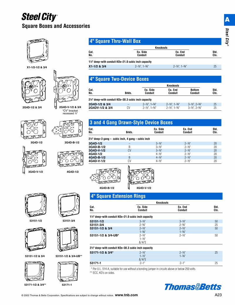
4" Square Thru-Wall BoxKnockouts
Cat. Ea. Side Ea. End Std.No. Conduit Conduit Ctn.
1d" deep–with conduit KOs–21.0 cubic inch capacity
X1-1/2 & 3/4 2–d", 1–f" 2–d", 1–f" 25X1-1/2-1/2 & 3/4
2G4D-1/2 & 3/4 2G4D-V-1/2 & 3/4“CV” bracketrecessed g"
3 and 4 Gang Drawn-Style Device BoxesCat. Ea. Side Ea. End Std.No. Brkts. Conduit Conduit Ctn.
2a" deep–3 gang – cubic inch, 4 gang – cubic inch
3G4D-1/2 – 3–d" 2–d" 203G4D-B-1/2 B 3–d" 2–d" 203G4D-V-1/2 CV 3–d" 2–d" 204G4D-1/2 – 4–d" 2–d" 204G4D-B-1/2 B 4–d" 2–d" 204G4D-V-1/2 CV 4–d" 2–d" 20
3G4D-V-1/2 4G4D-1/2
3G4D-1/2 3G4D-B-1/2
4G4D-B-1/2 4G4D-V-1/2
4" Square Two-Device BoxesKnockouts
Cat. Ea. Side Ea. End Bottom Std.No. Brkts. Conduit Conduit Conduit Ctn.
2a" deep–with conduit KOs–30.3 cubic inch capacity
2G4D-1/2 & 3/4 – 2–d", 1–f" 2–d", 1–f" 3–d", 2–f" 252G4DV-1/2 & 3/4 CV 2–d", 1–f" 2–d", 1–f" 3–d", 2–f" 25
4" Square Extension RingsKnockouts
Cat. Ea. Side Ea. End Std.No. Conduit Conduit Ctn.
1d" deep–with conduit KOs–21.0 cubic inch capacity
53151-1/2 3–d" 3–d" 5053151-3/4 2–f" 2–f" 2553151-1/2 & 3/4 2–d" 2–d" 50
1–f" 1–f"53151-1/2 & 3/4-UB* 2–d" 2–d" 50
1–d"& f"E
2a" deep–with conduit KOs–30.3 cubic inch capacity
53171-1/2 & 3/4* 2–d" 2–d" 251–d" 1–f"& f"E
53171-1 2–1" 2–1" 25
** Per U.L. 514-A, suitable for use without a bonding jumper in circuits above or below 250 volts.** ECC, KO’s on sides.
53151-1/2 53151-3/4
53151-1/2 & 3/4 53151-1/2 & 3/4-UB**
53171-1/2 & 3/4** 53171-1
A
Steel City®
A24 © 2003 Thomas & Betts Corporation. Specifications are subject to change without notice. www.tnb.com
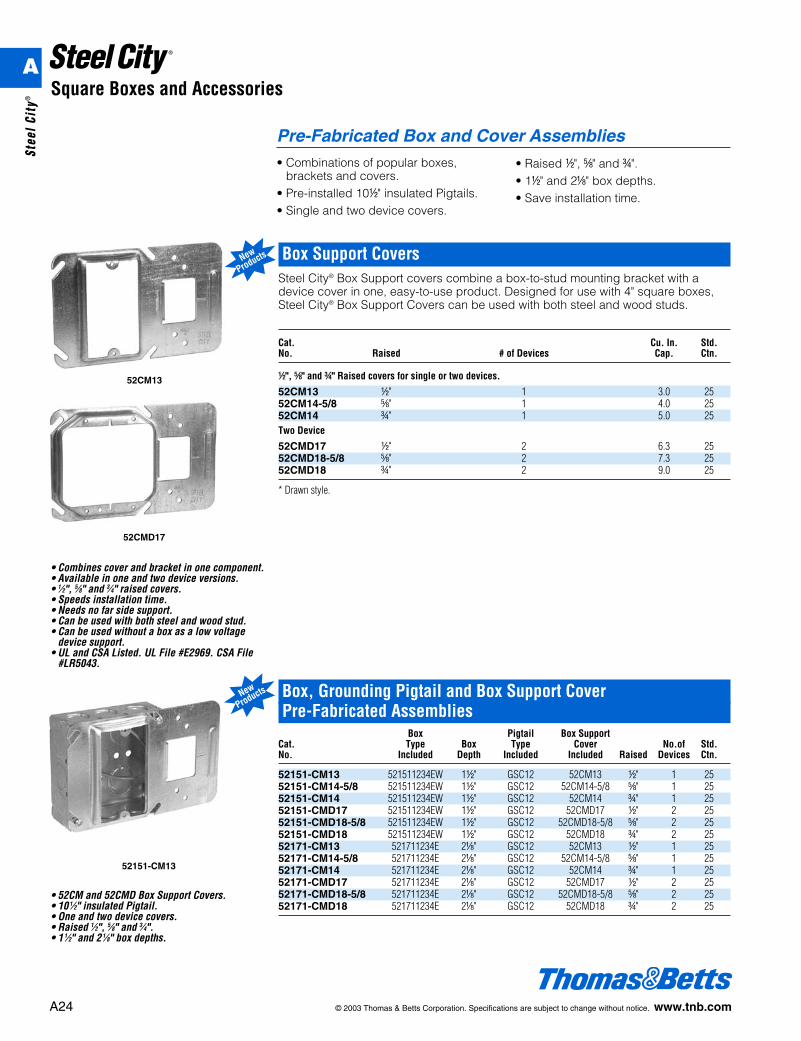
Box, Grounding Pigtail and Box Support Cover Pre-Fabricated Assemblies
Box Pigtail Box SupportCat. Type Box Type Cover No.of Std. No. Included Depth Included Included Raised Devices Ctn.
52151-CM13 521511234EW 1d" GSC12 52CM13 d" 1 2552151-CM14-5/8 521511234EW 1d" GSC12 52CM14-5/8 e" 1 2552151-CM14 521511234EW 1d" GSC12 52CM14 f" 1 2552151-CMD17 521511234EW 1d" GSC12 52CMD17 d" 2 2552151-CMD18-5/8 521511234EW 1d" GSC12 52CMD18-5/8 e" 2 2552151-CMD18 521511234EW 1d" GSC12 52CMD18 f" 2 2552171-CM13 521711234E 2a" GSC12 52CM13 d" 1 2552171-CM14-5/8 521711234E 2a" GSC12 52CM14-5/8 e" 1 2552171-CM14 521711234E 2a" GSC12 52CM14 f" 1 2552171-CMD17 521711234E 2a" GSC12 52CMD17 d" 2 2552171-CMD18-5/8 521711234E 2a" GSC12 52CMD18-5/8 e" 2 2552171-CMD18 521711234E 2a" GSC12 52CMD18 f" 2 25
52151-CM13
Square Boxes and Accessories
Pre-Fabricated Box and Cover Assemblies• Combinations of popular boxes,
brackets and covers.• Pre-installed 10d" insulated Pigtails.• Single and two device covers.
• Raised d", e" and f".• 1d" and 2a" box depths.• Save installation time.
Box Support CoversSteel City® Box Support covers combine a box-to-stud mounting bracket with adevice cover in one, easy-to-use product. Designed for use with 4" square boxes,Steel City® Box Support Covers can be used with both steel and wood studs.
Cat. Cu. In. Std.No. Raised # of Devices Cap. Ctn.
d", e" and f" Raised covers for single or two devices.
52CM13 d" 1 3.0 2552CM14-5/8 e" 1 4.0 2552CM14 f" 1 5.0 25Two Device
52CMD17 d" 2 6.3 2552CMD18-5/8 e" 2 7.3 2552CMD18 f" 2 9.0 25
* Drawn style.
52CM13
52CMD17
New
Products
• Combines cover and bracket in one component.• Available in one and two device versions.• 1⁄2", 5⁄8" and 3⁄4" raised covers.• Speeds installation time.• Needs no far side support.• Can be used with both steel and wood stud.• Can be used without a box as a low voltage
device support.• UL and CSA Listed. UL File #E2969. CSA File
#LR5043.
• 52CM and 52CMD Box Support Covers.• 10 1⁄2" insulated Pigtail.• One and two device covers.• Raised 1⁄2", 5⁄8" and 3⁄4".• 1 1⁄2" and 2 1⁄8" box depths.
New
Products
A
Stee
l Cit
y®
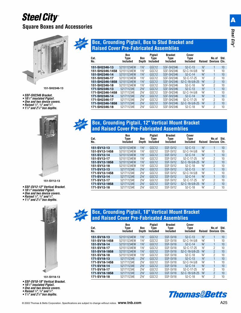
151-SH2346-13
© 2003 Thomas & Betts Corporation. Specifications are subject to change without notice. www.tnb.com A25
Square Boxes and Accessories
Box, Grounding Pigtail, Box to Stud Bracket and Raised Cover Pre-Fabricated Assemblies
Box Pigtail Bracket CoverCat. Type Box Type Type Type No.of Std. No. Included Depth Included Included Included Raised Devices Ctn.
151-SH2346-13 521511234EW 1d" GSC12 SSF-SH2346 52-C-13 d" 1 10151-SH2346-1458 521511234EW 1d" GSC12 SSF-SH2346 52-C-14-5/8 e" 1 10151-SH2346-14 521511234EW 1d" GSC12 SSF-SH2346 52-C-14 f" 1 10151-SH2346-17 521511234EW 1d" GSC12 SSF-SH2346 52-C-17-25 d" 2 10151-SH2346-1858 521511234EW 1d" GSC12 SSF-SH2346 52-C-18-5/8-25 e" 2 10151-SH2346-18 521511234EW 1d" GSC12 SSF-SH2346 52-C-18 f" 2 10171-SH2346-13 521711234E 2a" GSC12 SSF-SH2346 52-C-13 d" 1 10171-SH2346-1458 521711234E 2a" GSC12 SSF-SH2346 52-C-14-5/8 e" 1 10171-SH2346-14 521711234E 2a" GSC12 SSF-SH2346 52-C-14 f" 1 10171-SH2346-17 521711234E 2a" GSC12 SSF-SH2346 52-C-17-25 d" 2 10171-SH2346-1858 521711234E 2a" GSC12 SSF-SH2346 52-C-18-5/8-25 e" 2 10171-SH2346-18 521711234E 2a" GSC12 SSF-SH2346 52-C-18 f" 2 10
• SSF-SH2346 Bracket.• 10 1⁄2" insulated Pigtail.• One and two device covers.• Raised 1⁄2", 5⁄8" and 3⁄4".• 1 1⁄2" and 2 1⁄8" box depths.
New
Products
Box, Grounding Pigtail, 12" Vertical Mount Bracket and Raised Cover Pre-Fabricated Assemblies
Box Pigtail Bracket CoverCat. Type Box Type Type Type No.of Std. No. Included Depth Included Included Included Raised Devices Ctn.
151-SV12-13 521511234EW 1d" GSC12 SSF-SV12 52-C-13 d" 1 10151-SV12-1458 521511234EW 1d" GSC12 SSF-SV12 52-C-14-5/8 e" 1 10151-SV12-14 521511234EW 1d" GSC12 SSF-SV12 52-C-14 f" 1 10151-SV12-17 521511234EW 1d" GSC12 SSF-SV12 52-C-17-25 d" 2 10151-SV12-1858 521511234EW 1d" GSC12 SSF-SV12 52-C-18-5/8-25 e" 2 10151-SV12-18 521511234EW 1d" GSC12 SSF-SV12 52-C-18 f" 2 10171-SV12-13 521711234E 2a" GSC12 SSF-SV12 52-C-13 d" 1 10171-SV12-1458 521711234E 2a" GSC12 SSF-SV12 52-C-14-5/8 e" 1 10171-SV12-14 521711234E 2a" GSC12 SSF-SV12 52-C-14 f" 1 10171-SV12-17 521711234E 2a" GSC12 SSF-SV12 52-C-17-25 d" 2 10171-SV12-1858 521711234E 2a" GSC12 SSF-SV12 52-C-18-5/8-25 e" 2 10171-SV12-18 521711234E 2a" GSC12 SSF-SV12 52-C-18 f" 2 10
151-SV12-13
151-SV18-13
Box, Grounding Pigtail, 18" Vertical Mount Bracket and Raised Cover Pre-Fabricated Assemblies
Box Pigtail Bracket CoverCat. Type Box Type Type Type No.of Std. No. Included Depth Included Included Included Raised Devices Ctn.
151-SV18-13 521511234EW 1d" GSC12 SSF-SV18 52-C-13 d" 1 10151-SV18-1458 521511234EW 1d" GSC12 SSF-SV18 52-C-14-5/8 e" 1 10151-SV18-14 521511234EW 1d" GSC12 SSF-SV18 52-C-14 f" 1 10151-SV18-17 521511234EW 1d" GSC12 SSF-SV18 52-C-17-25 d" 2 10151-SV18-1858 521511234EW 1d" GSC12 SSF-SV18 52-C-18-5/8-25 e" 2 10151-SV18-18 521511234EW 1d" GSC12 SSF-SV18 52-C-18 f" 2 10171-SV18-13 521711234E 2a" GSC12 SSF-SV18 52-C-13 d" 1 10171-SV18-1458 521711234E 2a" GSC12 SSF-SV18 52-C-14-5/8 e" 1 10171-SV18-14 521711234E 2a" GSC12 SSF-SV18 52-C-14 f" 1 10171-SV18-17 521711234E 2a" GSC12 SSF-SV18 52-C-17-25 d" 2 10171-SV18-1858 521711234E 2a" GSC12 SSF-SV18 52-C-18-5/8-25 e" 2 10171-SV18-18 521711234E 2a" GSC12 SSF-SV18 52-C-18 f" 2 10
New
Products
New
Products
• SSF-SV12-12" Vertical Bracket.• 10 1⁄2" insulated Pigtail.• One and two device covers.• Raised 1⁄2", 5⁄8" and 3⁄4".• 1 1⁄2" and 2 1⁄8" box depths.
• SSF-SV18-18" Vertical Bracket.• 10 1⁄2" insulated Pigtail.• One and two device covers.• Raised 1⁄2", 5⁄8" and 3⁄4".• 1 1⁄2" and 2 1⁄8" box depths.
A
Steel City®
A26 © 2003 Thomas & Betts Corporation. Specifications are subject to change without notice. www.tnb.com
Square Boxes and Accessories
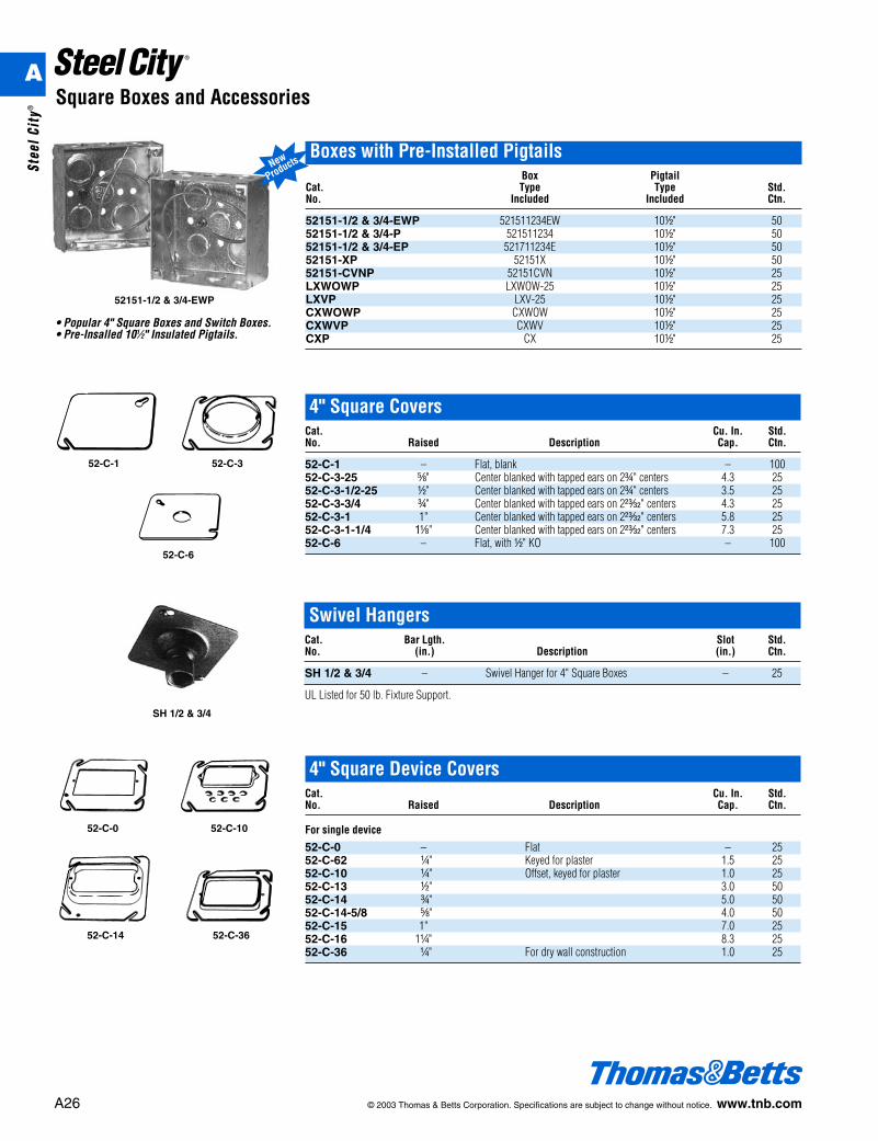
52151-1/2 & 3/4-EWP
Boxes with Pre-Installed PigtailsBox Pigtail
Cat. Type Type Std. No. Included Included Ctn.
52151-1/2 & 3/4-EWP 521511234EW 10d" 5052151-1/2 & 3/4-P 521511234 10d" 5052151-1/2 & 3/4-EP 521711234E 10d" 5052151-XP 52151X 10d" 5052151-CVNP 52151CVN 10d" 25LXWOWP LXWOW-25 10d" 25LXVP LXV-25 10d" 25CXWOWP CXWOW 10d" 25CXWVP CXWV 10d" 25CXP CX 10d" 25
New
Products
• Popular 4" Square Boxes and Switch Boxes.• Pre-Insalled 101⁄2" Insulated Pigtails.
52-C-1 52-C-3
52-C-6
4" Square CoversCat. Cu. In. Std.No. Raised Description Cap. Ctn.
52-C-1 – Flat, blank – 10052-C-3-25 e" Center blanked with tapped ears on 2f" centers 4.3 2552-C-3-1/2-25 d" Center blanked with tapped ears on 2f" centers 3.5 2552-C-3-3/4 f" Center blanked with tapped ears on 2z" centers 4.3 2552-C-3-1 1" Center blanked with tapped ears on 2z" centers 5.8 2552-C-3-1-1/4 1a" Center blanked with tapped ears on 2z" centers 7.3 2552-C-6 – Flat, with d" KO – 100
Swivel HangersCat. Bar Lgth. Slot Std.No. (in.) Description (in.) Ctn.
SH 1/2 & 3/4 – Swivel Hanger for 4" Square Boxes – 25
UL Listed for 50 lb. Fixture Support.
SH 1/2 & 3/4
4" Square Device CoversCat. Cu. In. Std.No. Raised Description Cap. Ctn.
For single device
52-C-0 – Flat – 2552-C-62 b" Keyed for plaster 1.5 2552-C-10 b" Offset, keyed for plaster 1.0 2552-C-13 d" 3.0 5052-C-14 f" 5.0 5052-C-14-5/8 e" 4.0 5052-C-15 1" 7.0 2552-C-16 1b" 8.3 2552-C-36 b" For dry wall construction 1.0 25
52-C-14 52-C-36
52-C-0 52-C-10
A
Stee
l Cit
y®
© 2003 Thomas & Betts Corporation. Specifications are subject to change without notice. www.tnb.com A27
Square Boxes and Accessories
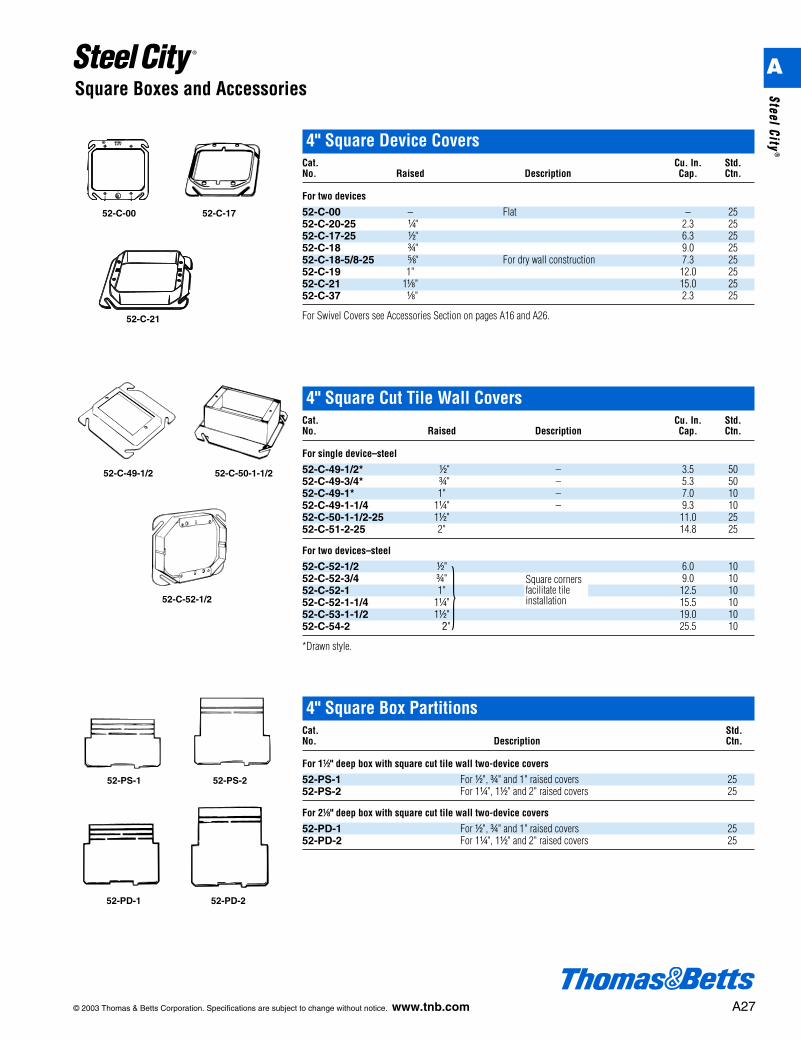
4" Square Device CoversCat. Cu. In. Std.No. Raised Description Cap. Ctn.
For two devices
52-C-00 – Flat – 2552-C-20-25 b" 2.3 2552-C-17-25 d" 6.3 2552-C-18 f" 9.0 2552-C-18-5/8-25 e" For dry wall construction 7.3 2552-C-19 1" 12.0 2552-C-21 1a" 15.0 2552-C-37 a" 2.3 25
For Swivel Covers see Accessories Section on pages A16 and A26.52-C-21
52-C-00 52-C-17
4" Square Cut Tile Wall CoversCat. Cu. In. Std.No. Raised Description Cap. Ctn.
For single device–steel
52-C-49-1/2* d" – 3.5 5052-C-49-3/4* f" – 5.3 5052-C-49-1* 1" – 7.0 1052-C-49-1-1/4 1b" – 9.3 1052-C-50-1-1/2-25 1d" 11.0 2552-C-51-2-25 2" 14.8 25
For two devices–steel
52-C-52-1/2 d" 6.0 1052-C-52-3/4 f" 9.0 1052-C-52-1 1" 12.5 1052-C-52-1-1/4 1b" 15.5 1052-C-53-1-1/2 1d" 19.0 1052-C-54-2 2"
}25.5 10
*Drawn style.
52-C-52-1/2
52-C-49-1/2 52-C-50-1-1/2
4" Square Box PartitionsCat. Std.No. Description Ctn.
For 1d" deep box with square cut tile wall two-device covers
52-PS-1 For d", f" and 1" raised covers 2552-PS-2 For 1b", 1d" and 2" raised covers 25
For 2a" deep box with square cut tile wall two-device covers
52-PD-1 For d", f" and 1" raised covers 2552-PD-2 For 1b", 1d" and 2" raised covers 25
52-PS-1 52-PS-2
52-PD-1 52-PD-2
Square cornersfacilitate tileinstallation
A
Steel City®
A28 © 2003 Thomas & Betts Corporation. Specifications are subject to change without notice. www.tnb.com
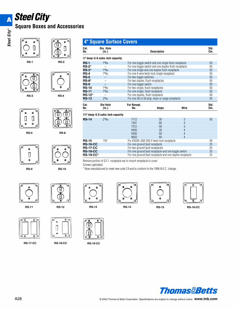
4" Square Surface CoversCat. Dia. Hole Std.No. (in.) Description Ctn.
d" deep–5.0 cubic inch capacity
RS-1 1u For one toggle switch and one single flush receptacle 50RS-2* – For one toggle switch and one duplex flush receptacle 50RS-3* 1u For one single and one duplex flush receptacle 50RS-4 1x For one 4-wire twist-lock single receptacle 50RS-5 – For two toggle switches 50RS-8* – For two duplex, flush receptacles 50RS-9 – For one toggle switch 50RS-10 1u For two single, flush receptacles 50RS-11 1u For one single, flush receptacle 50RS-12* – For one duplex, flush receptacle 50RS-13 2q For one 30 or 50 amp. dryer or range receptacle 50
Cat. Die Hole For Recept. Std.No. (in.) No. Amps Wire Ctn.
1d" deep–5.0 cubic inch capacity
RS-14 2v 7112 30 3 507301 60 47512 50 39430 30 49430 50 49650 60 4
RS-15 1f" For #3330–30A 250 V twist-lock receptacle 50RS-16-CC For one ground fault receptacle 25RS-17-CC For two ground fault receptacles 25RS-18-CC For one ground fault receptacle and one toggle switch 25RS-19-CC* For one ground fault receptacle and one duplex receptacle 25
Remove portion of G.F.I. receptacle ear to mount receptacle to cover.Screws captivated.* Now manufactured to meet new code C4 and to conform to the 1996 N.E.C. change.
RS-1 RS-2
RS-3 RS-4
RS-5 RS-8
RS-9 RS-10
RS-11 RS-12 RS-13 RS-16-CC
RS-17-CC RS-18-CC RS-19-CC
RS-14 RS-15
Square Boxes and AccessoriesA
Stee
l Cit
y®
© 2003 Thomas & Betts Corporation. Specifications are subject to change without notice. www.tnb.com A29
Square Boxes and Accessories
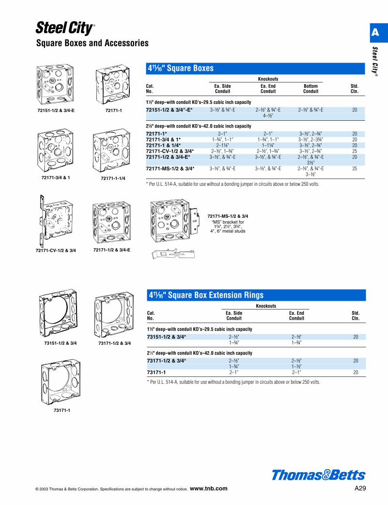
4L" Square BoxesKnockouts
Cat. Ea. Side Ea. End Bottom Std.No. Conduit Conduit Conduit Ctn.
1d" deep–with conduit KO’s–29.5 cubic inch capacity
72151-1/2 & 3/4"-E* 3–d" & f"-E 2–d" & f"-E 2–d" & f"-E 204–d"
2a" deep–with conduit KO’s–42.0 cubic inch capacity
72171-1* 2–1" 2–1" 3–d", 2–f" 2072171-3/4 & 1* 1–f", 1–1" 1–f", 1–1" 3–d", 2–3f" 2072171-1 & 1/4* 2–1b" 1–1b" 3–d", 2–f" 2072171-CV-1/2 & 3/4* 2–d", 1–f" 2–d", 1–f" 3–d", 2–f" 2572171-1/2 & 3/4-E* 3–d", & f"-E 3–d", & f"-E 2–d", & f"-E 20
3d"72171-MS-1/2 & 3/4* 3–d", & f"-E 3–d", & f"-E 2–d", & f"-E 25
3–d"
* Per U.L. 514-A, suitable for use without a bonding jumper in circuits above or below 250 volts.
72151-1/2 & 3/4-E 72171-1
72171-CV-1/2 & 3/4 72171-1/2 & 3/4-E
72171-3/4 & 1 72171-1-1/4
72171-MS-1/2 & 3/4“MS” bracket for1e", 2d", 3e",
4", 6" metal studs
4L" Square Box Extension RingsKnockouts
Cat. Ea. Side Ea. End Std.No. Conduit Conduit Ctn.
1d" deep–with conduit KO’s–29.5 cubic inch capacity
73151-1/2 & 3/4* 2–d" 2–d" 201–f" 1–f"
2a" deep–with conduit KO’s–42.0 cubic inch capacity
73171-1/2 & 3/4* 2–d" 2–d" 201–f" 1–d"
73171-1 2–1" 2–1" 20
* Per U.L. 514-A, suitable for use without a bonding jumper in circuits above or below 250 volts.
73151-1/2 & 3/4 73171-1/2 & 3/4
73171-1
A
Steel City®
A30 © 2003 Thomas & Betts Corporation. Specifications are subject to change without notice. www.tnb.com
Square Boxes and Accessories
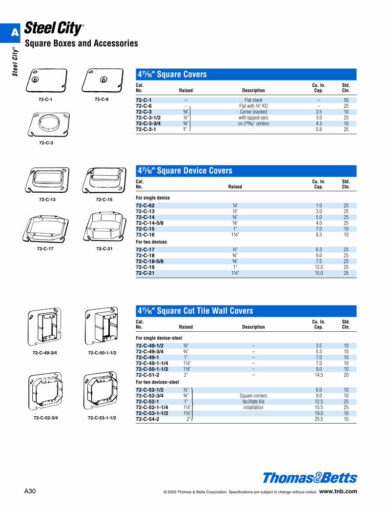
4L" Square Device CoversCat. Cu. In. Std.No. Raised Cap. Ctn.
For single device
72-C-62 b" 1.0 2572-C-13 d" 3.0 2572-C-14 f" 5.0 2572-C-14-5/8 e" 4.0 2572-C-15 1" 7.0 1072-C-16 1b" 8.3 10For two devices
72-C-17 d" 6.3 2572-C-18 f" 9.0 2572-C-18-5/8 e" 7.5 2572-C-19 1" 12.0 2572-C-21 1b" 15.0 25
72-C-13 72-C-15
72-C-17 72-C-21
4L" Square Cut Tile Wall CoversCat. Cu. In. Std.No. Raised Description Cap. Ctn.
For single device–steel
72-C-49-1/2 d" – 3.5 1072-C-49-3/4 f" – 5.3 1072-C-49-1 1" – 7.0 1072-C-49-1-1/4 1b" – 7.0 1072-C-50-1-1/2 1d" – 9.0 1072-C-51-2 2" – 14.5 20For two devices–steel
72-C-52-1/2 d" 6.0 1072-C-52-3/4 f" Square corners 9.0 1072-C-52-1 1" facilitate tile 12.5 2572-C-52-1-1/4 1b" installation 15.5 2572-C-53-1-1/2 1d" 19.0 1072-C-54-2 2"
}25.5 10
72-C-49-3/4 72-C-50-1-1/2
72-C-52-3/4 72-C-53-1-1/2
4L" Square CoversCat. Cu. In. Std.No. Raised Description Cap. Ctn.
72-C-1 – Flat blank – 5072-C-6 – Flat with d" KO – 2572-C-3 e" Center blanked 3.5 1072-C-3-1/2 d" with tapped ears 3.0 2572-C-3-3/4 f" on 2z" centers 4.3 1072-C-3-1 1"
}5.8 25
72-C-3
72-C-1 72-C-6
A
Stee
l Cit
y®
© 2003 Thomas & Betts Corporation. Specifications are subject to change without notice. www.tnb.com A31
Square Boxes and Accessories
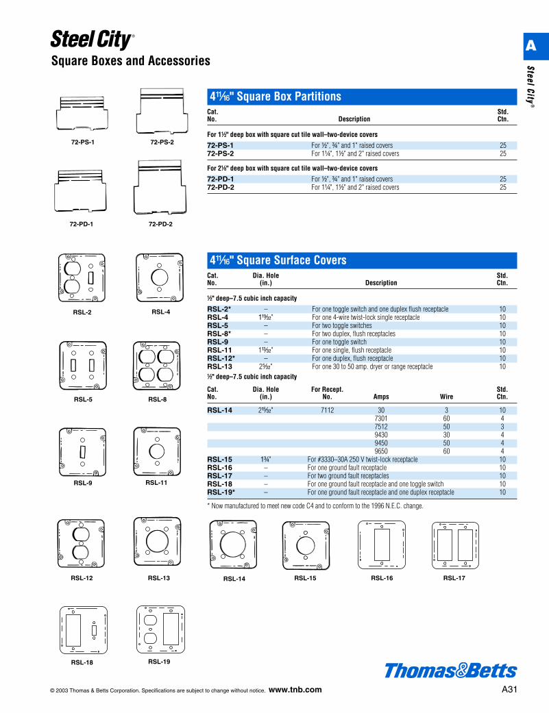
4L" Square Box PartitionsCat. Std.No. Description Ctn.
For 1d" deep box with square cut tile wall–two-device covers
72-PS-1 For d", f" and 1" raised covers 2572-PS-2 For 1b", 1d" and 2" raised covers 25
For 2a" deep box with square cut tile wall–two-device covers
72-PD-1 For d", f" and 1" raised covers 2572-PD-2 For 1b", 1d" and 2" raised covers 25
72-PS-1 72-PS-2
72-PD-1 72-PD-2
4L" Square Surface CoversCat. Dia. Hole Std.No. (in.) Description Ctn.
d" deep–7.5 cubic inch capacity
RSL-2* – For one toggle switch and one duplex flush receptacle 10RSL-4 1x" For one 4-wire twist-lock single receptacle 10RSL-5 – For two toggle switches 10RSL-8* – For two duplex, flush receptacles 10RSL-9 – For one toggle switch 10RSL-11 1u" For one single, flush receptacle 10RSL-12* – For one duplex, flush receptacle 10RSL-13 2q" For one 30 to 50 amp. dryer or range receptacle 10d" deep–7.5 cubic inch capacity
Cat. Dia. Hole For Recept. Std.No. (in.) No. Amps Wire Ctn.
RSL-14 2v" 7112 30 3 107301 60 47512 50 39430 30 49450 50 49650 60 4
RSL-15 1f" For #3330–30A 250 V twist-lock receptacle 10RSL-16 – For one ground fault receptacle 10RSL-17 – For two ground fault receptacles 10RSL-18 – For one ground fault receptacle and one toggle switch 10RSL-19* – For one ground fault receptacle and one duplex receptacle 10
* Now manufactured to meet new code C4 and to conform to the 1996 N.E.C. change.
RSL-2 RSL-4
RSL-5 RSL-8
RSL-9 RSL-11
RSL-12 RSL-13 RSL-14 RSL-15 RSL-16 RSL-17
RSL-18 RSL-19
A
Steel City®
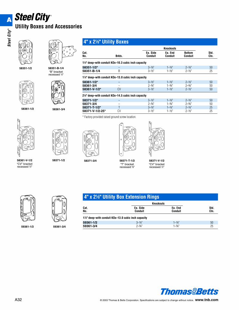
4" x 2a" Utility BoxesKnockouts
Cat. Ea. Side Ea. End Bottom Std.No. Brkts. Conduit Conduit Conduit Ctn.
1d" deep–with conduit KOs–10.3 cubic inch capacity
58351-1/2* – 3–d" 1–d" 2–d" 5058351-B-1/4 B 3–d" 1–d" 2–d" 25
1g" deep–with conduit KOs–13.0 cubic inch capacity
58361-1/2* – 3–d" 1–d" 2–d" 5058361-3/4 – 2–f" 1–f" 2–f" 5058361-V-1/2* CV 3–d" 1–d" 2–d" 50
2a" deep–with conduit KOs–14.5 cubic inch capacity
58371-1/2* – 3–d" 1–d" 2–d" 5058371-3/4 – 2–f" 1–f" 2–f" 5058371-T-1/2* T 3–d" 1–d" 2–d" 2558371-V-1/2-25* CV 3–d" 1–d" 2–d" 25
* Factory provided raised ground screw location.
A32 © 2003 Thomas & Betts Corporation. Specifications are subject to change without notice. www.tnb.com
Utility Boxes and Accessories
4" x 2a" Utility Box Extension RingsKnockouts
Cat. Ea. Side Ea. End Std.No. Conduit Conduit Ctn.
1g" deep–with conduit KOs–13.0 cubic inch capacity
59361-1/2 3–d" 1–d" 5059361-3/4 2–f" 1–f" 25
58351-1/2 58351-B-1/4“B” bracketrecessed b"
58361-1/2 58361-3/4
58361-V-1/2“CV” bracketrecessed d"
58371-3/4 58371-T-1/2“T” bracket
recessed e"
58371-V-1/2“CV” bracketrecessed d"
58371-1/2
59361-1/2 59361-3/4
A
Stee
l Cit
y®
© 2003 Thomas & Betts Corporation. Specifications are subject to change without notice. www.tnb.com A33
Utility Boxes and Accessories
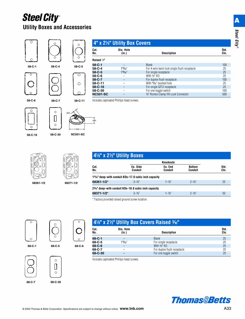
4" x 2a" Utility Box CoversCat. Dia. Hole Std.No. (in.) Description Ctn.
Raised b"
58-C-1 – Blank 10058-C-4 1x" For 4-wire twist-lock single flush receptacle 2558-C-5 1u" For single receptacle 2558-C-6 – With d" KO 2558-C-7 – For duplex flush receptacle 10058-C-11 – With v" bushed hole 2558-C-16 – For single GFCI receptacle 2558-C-30 – For one toggle switch 100NC501-SC – d" Romex Clamp Hit Lock Connector 500
Includes captivated Phillips head screws.58-C-7 58-C-11
58-C-16 58-C-30
58-C-1 58-C-4 58-C-5
58-C-6
68361-1/2 68371-1/2
68-C-7 68-C-30
68-C-1 68-C-5 68-C-6
4a" x 2d" Utility BoxesKnockouts
Cat. Ea. Side Ea. End Bottom Std.No. Conduit Conduit Conduit Ctn.
1n" deep–with conduit KOs–17.0 cubic inch capacity
68361-1/2* 3–d" 1–d" 2–d" 25
2l" deep–with conduit KOs–18.8 cubic inch capacity
68371-1/2* 3–d" 1–d" 2–d" 50
* Factory provided raised ground screw location.
.400
.580
1.030
NC501-SC
4a" x 2d" Utility Box Covers Raised i"Cat. Dia. Hole Std.No. (in.) Description Ctn.
68-C-1 – Blank 2568-C-5 1u" For single receptacle 2568-C-6 – With d" KO 2568-C-7 – For duplex flush receptacle 2568-C-30 – For one toggle switch 25
Includes captivated Phillips head screws.
A
Steel City®
A34 © 2003 Thomas & Betts Corporation. Specifications are subject to change without notice. www.tnb.com
Gang Boxes and Accessories
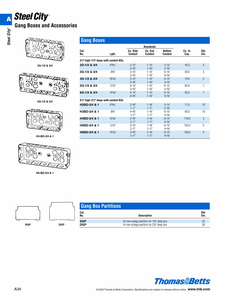
Gang BoxesKnockouts
Cat. Ea. Side Ea. End Bottom Cu. In. Std.No. Lgth. Conduit Conduit Conduit Cap. Ctn.
4d" high–1e" deep–with conduit KOs
2G-1/2 & 3/4 6m" 2–d" 1–d" 3–d" 45.0 52–f" 1–f" 2–f"
3G-1/2 & 3/4 8e" 3–d" 1–d" 6–d" 58.0 52–f" 1–f" 4–f"
4G-1/2 & 3/4 10k" 3–d" 1–d" 6–d" 70.0 53–f" 1–f" 4–f"
5G-1/2 & 3/4 12b" 4–d" 1–d" 6–d" 85.0 13–f" 1–f" 4–f"
6G-1/2 & 3/4 14h" 4–d" 1–d" 6–d" 95.0 14–f" 1–f" 4–f"
4d" high–2d" deep–with conduit KOs
H2BD-3/4 & 1 6m" 2–f" 1–f" 3–d" 71.0 101–1" 1–1" 2–f"
H3BD-3/4 & 1 8e" 4–f" 1–f" 6–d" 90.0 101–1" 1–1" 4–f"
H4BD-3/4 & 1 10k" 2–f" 1–f" 6–d" 110.0 52–1" 1–1" 4–f"
H5BD-3/4 & 1 12b" 3–f" 1–f" 6–d" 132.0 52–1" 1–1" 4–f"
H6BD-3/4 & 1 14h" 3–f" 1–f" 6–d" 150.0 53–1" 1–1" 4–f"
Gang Box PartitionsCat. Std.No. Description Ctn.
SGP Hi-low voltage partition for 1e" deep box 25DGP Hi-low voltage partition for 2d" deep box 50SGP DGP
3G-1/2 & 3/4
5G-1/2 & 3/4
H3-BD-3/4 & 1
H5-BD-3/4 & 1
A
Stee
l Cit
y®
© 2003 Thomas & Betts Corporation. Specifications are subject to change without notice. www.tnb.com A35
Gang Boxes and Accessories
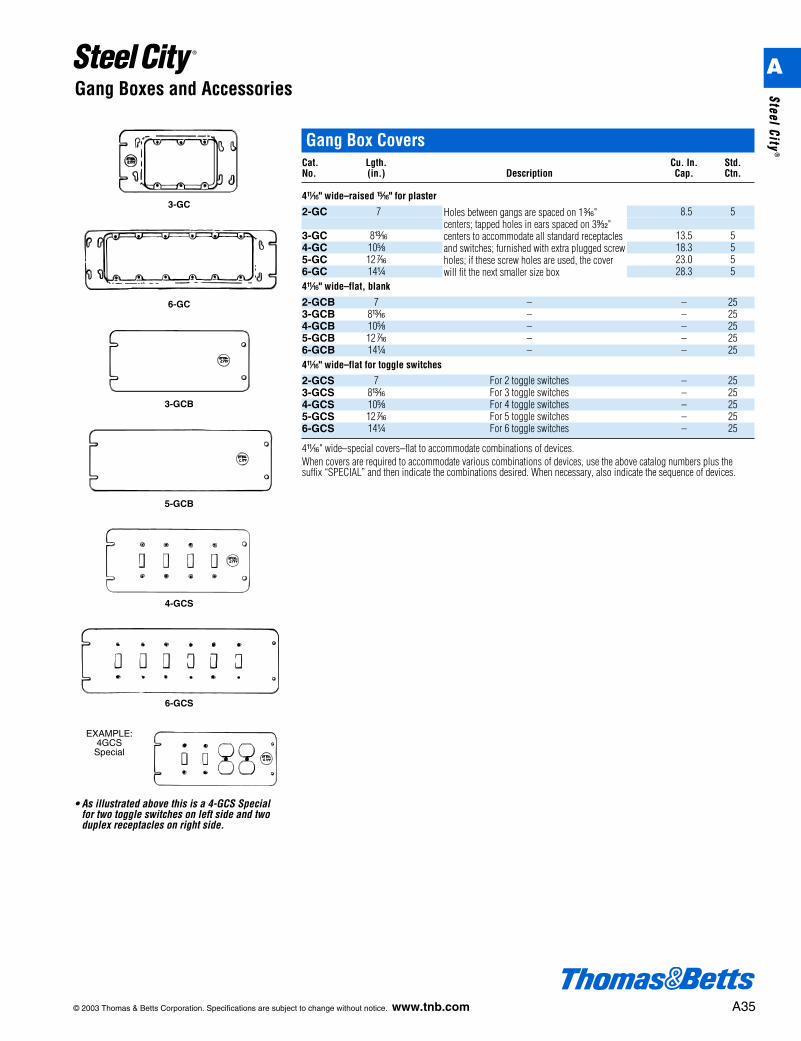
Gang Box CoversCat. Lgth. Cu. In. Std.No. (in.) Description Cap. Ctn.
4L" wide–raised n" for plaster
2-GC 7 8.5 5
3-GC 8m 13.5 54-GC 10e 18.3 55-GC 12k 23.0 56-GC 14b 28.3 54L" wide–flat, blank
2-GCB 7 – – 253-GCB 8m – – 254-GCB 10e – – 255-GCB 12k – – 256-GCB 14b – – 254L" wide–flat for toggle switches
2-GCS 7 For 2 toggle switches – 253-GCS 8m For 3 toggle switches – 254-GCS 10e For 4 toggle switches – 255-GCS 12k For 5 toggle switches – 256-GCS 14b For 6 toggle switches – 25
4L" wide–special covers–flat to accommodate combinations of devices.When covers are required to accommodate various combinations of devices, use the above catalog numbers plus thesuffix “SPECIAL” and then indicate the combinations desired. When necessary, also indicate the sequence of devices.
3-GC
6-GC
3-GCB
5-GCB
4-GCS
6-GCS
• As illustrated above this is a 4-GCS Special for two toggle switches on left side and twoduplex receptacles on right side.
EXAMPLE:4GCSSpecial
Holes between gangs are spaced on 1i"centers; tapped holes in ears spaced on 3s"centers to accommodate all standard receptaclesand switches; furnished with extra plugged screwholes; if these screw holes are used, the coverwill fit the next smaller size box
A
Steel City®
A36 © 2003 Thomas & Betts Corporation. Specifications are subject to change without notice. www.tnb.com
Concrete Boxes and Accessories
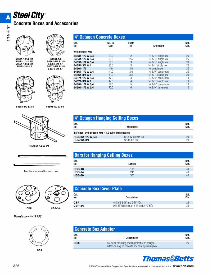
4" Octagon Concrete BoxesCat. Cu. In. Depth Std.No. Cap. (In.) Knockouts Ctn.
With conduit KOs
54531-1/2 & 3/4 23.0 2 d" & f" single row 2554541-1/2 & 3/4 29.0 2d d" & f" single row 2554551-1/2 & 3/4 35.0 3 d" & f" single row 2054551-3/4 & 1 35.0 3 f" & 1" single row 2054561-1/2 4.0 3d d" double row 2054561-1/2 & 3/4 41.0 3d d" & f" double row 2054561-3/4 & 1 41.0 3d f" & 1" double row 2054571-1/2 & 3/4 47.0 4 d" & f" double row 1054571-3/4 & 1 47.0 4 f" & 1" double row 1054581-1/2 & 3/4 58.0 5 d" & f" double row 1054591-1/2 & 3/4 70.0 6 d" & f" three rows 10
54531-1/2 & 3/454541-1/2 & 3/454551-1/2 & 3/454551-3/4 & 1
54561-1/254561-1/2 & 3/454561-3/4 & 1
54571-1/2 & 3/454571-3/4 & 1
54581-1/2 & 3/4 54591-1/2 & 3/4
H-54561-1/2 & 3/4
4" Octagon Hanging Ceiling BoxesCat. Std.No. Knockouts Ctn.
3d" deep–with conduit KOs–41.0 cubic inch capacity
H-54561-1/2 & 3/4 d" & f" double row 20H-54561-3/4 f" double row 20
CBA
Bars for Hanging Ceiling BoxesCat. Std.No. Length Ctn.
HBB-18 18" 40HBB-24 24" 40HBB-30 30" 40
CBP CBP-3/8
Two bars required for each box.
Concrete Box Cover PlateCat. Std.No. Description Ctn.
CBP No Stud. 3-d" and 2-f" KOs 25CBP-3/8 With c" fixture stud; 2-d" and 2-f" KOs 25
Concrete Box AdapterCat. Std.No. Description Ctn.
CBA For quick mounting and alignment of 4" octagon 25extension ring on concrete box or hung ceiling box
Thread size – 3⁄8 -18 NPS
A
Stee
l Cit
y®
© 2003 Thomas & Betts Corporation. Specifications are subject to change without notice. www.tnb.com A37
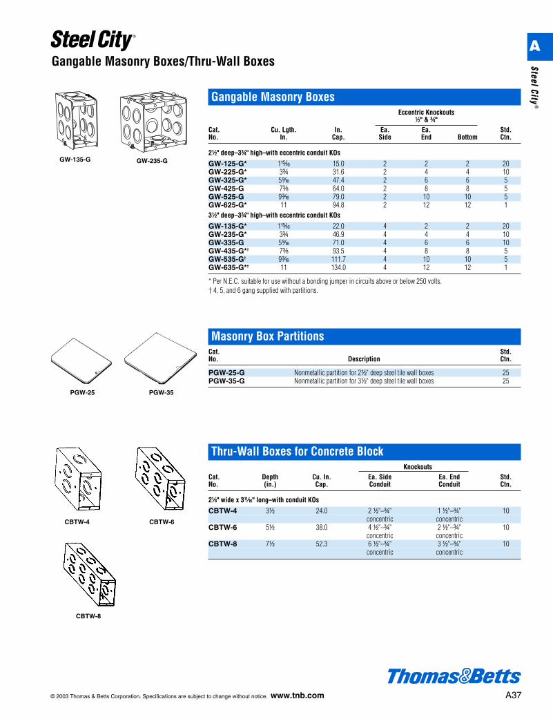
Gangable Masonry Boxes/Thru-Wall Boxes
PGW-25 PGW-35
Gangable Masonry BoxesEccentric Knockouts
d" & f"Cat. Cu. Lgth. In. Ea. Ea. Std.No. In. Cap. Side End Bottom Ctn.
2d" deep–3f" high–with eccentric conduit KOs
GW-125-G* 1n 15.0 2 2 2 20GW-225-G* 3f 31.6 2 4 4 10GW-325-G* 5l 47.4 2 6 6 5GW-425-G 7c 64.0 2 8 8 5GW-525-G 9i 79.0 2 10 10 5GW-625-G* 11 94.8 2 12 12 13d" deep–3f" high–with eccentric conduit KOs
GW-135-G* 1n 22.0 4 2 2 20GW-235-G* 3f 46.9 4 4 4 10GW-335-G 5l 71.0 4 6 6 10GW-435-G*† 7c 93.5 4 8 8 5GW-535-G† 9i 111.7 4 10 10 5GW-635-G*† 11 134.0 4 12 12 1
* Per N.E.C. suitable for use without a bonding jumper in circuits above or below 250 volts.† 4, 5, and 6 gang supplied with partitions.
GW-135-G GW-235-G
Masonry Box PartitionsCat. Std.No. Description Ctn.
PGW-25-G Nonmetallic partition for 2d" deep steel tile wall boxes 25PGW-35-G Nonmetallic partition for 3d" deep steel tile wall boxes 25
Thru-Wall Boxes for Concrete BlockKnockouts
Cat. Depth Cu. In. Ea. Side Ea. End Std.No. (in.) Cap. Conduit Conduit Ctn.
2a" wide x 3L" long–with conduit KOs
CBTW-4 3d 24.0 2 d"–f" 1 d"–f" 10concentric concentric
CBTW-6 5d 38.0 4 d"–f" 2 d"–f" 10concentric concentric
CBTW-8 7d 52.3 6 d"–f" 3 d"–f" 10concentric concentric
CBTW-4 CBTW-6
CBTW-8
A
Steel City®
A38 © 2003 Thomas & Betts Corporation. Specifications are subject to change without notice. www.tnb.com
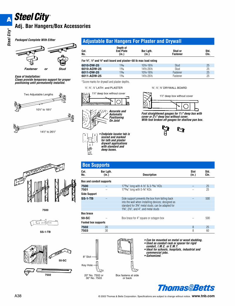
Adj. Bar Hangers/Box Accessories
d", f", g" LATH and PLASTER
Adjustable Bar Hangers For Plaster and DrywallDepth of
Cat. End Plate Bar Lgth. Stud or Std.No. (in.) (in.) Fastener Ctn.
For c", d" and e" wall board and plaster–50 lb max load rating
6010-DW-25 1i 10d-18d Stud 256010-ADW-25 1i 14d-26d Stud 256011-DW-25 1i 10d-18d Fastener 256011-ADW-25 1i 14d-26d Fastener 25
*Score marks for drywall and plaster depths.
Packaged Complete With Either
Ease of Installation:Claws provide temporary support for properpositioning until permanently installed.
Two Adjustable Lengths
Accurate andAutomaticPositioningOn Joist
14d" to 26d"
10d" to 18d"
• Endplate locator tab isscored and markedfor lath and plasterdrywall applicationswith standard anddeep boxes.
Foot straightened gauges for 11⁄2" deep box withcover or 21⁄8" deep box without cover.With foot broken off gauges for shallow pan box.
1d" deep box without cover1d" deep box without cover
c", d", e" DRYWALL BOARD
Fastener or Stud
• Can be mounted on metal or wood studding.• Used as conduit rack or spacer for rigid
conduit, I.M.C. or E.M.T.• Ideal for schools, hospitals, industrial and
commercial jobs.• Galvanized.
7500
50-SC
20" No. 7502 or30" No. 7503
Box fastens at sideor back
SS-1-TB
7502
8" Slot
Key Hole
Box SupportsCat. Bar Lgth. Slot Std.No. (in.) Description (in.) Ctn.
Box and conduit supports
7500 – 17n" long with 4-d" & 3-n" KOs – 257501 – 17n" long with 5-f" KOs – 25Side Support
SS-1-TB – Side support prevents the box from falling back – 500into the wall when installing devices; designed as standard for 3e" metal studs; can be adapted for1e", 2d", and 4", and metal studs
Box brace
50-SC – Box brace for 4" square or octagon box – 500Footed box supports
7502 20 8 257503 30 8 60
A
Stee
l Cit
y®
© 2003 Thomas & Betts Corporation. Specifications are subject to change without notice. www.tnb.com A39
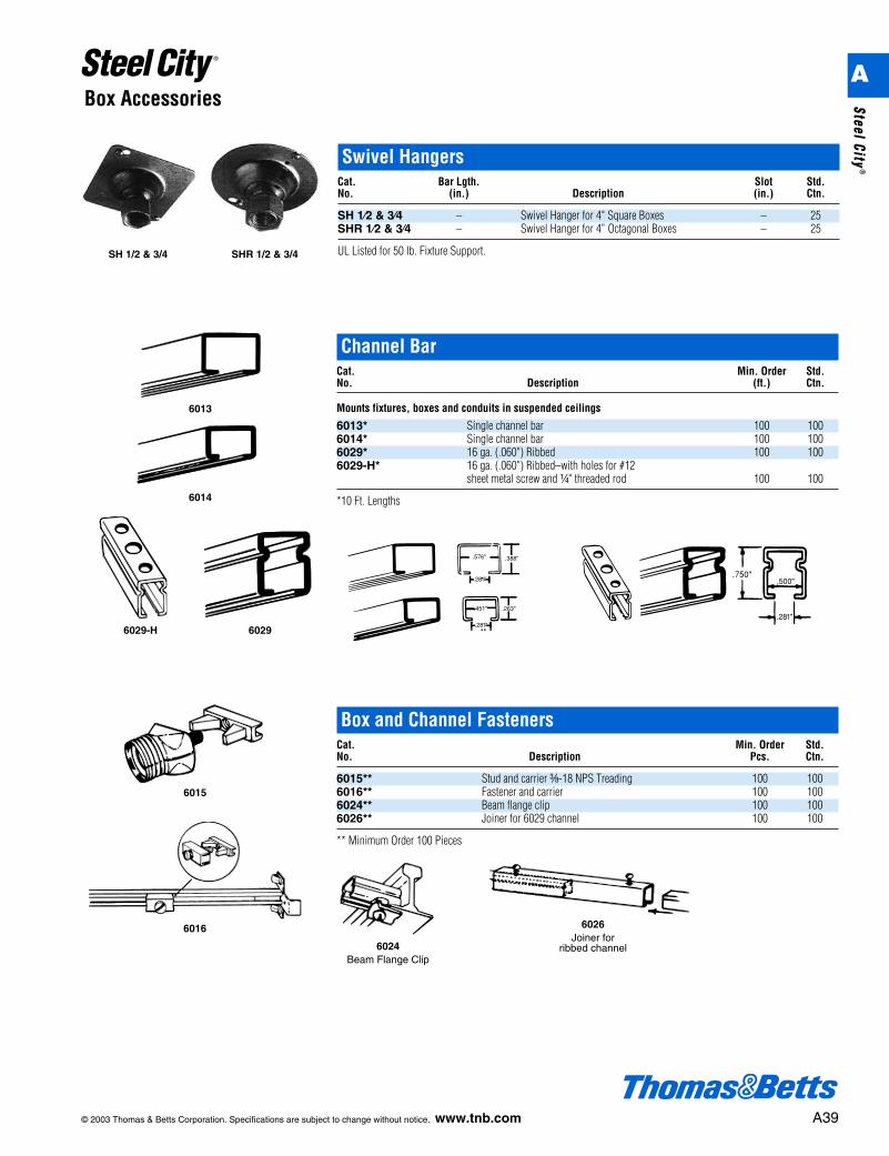
Box Accessories
Box and Channel FastenersCat. Min. Order Std.No. Description Pcs. Ctn.
6015** Stud and carrier c-18 NPS Treading 100 1006016** Fastener and carrier 100 1006024** Beam flange clip 100 1006026** Joiner for 6029 channel 100 100
** Minimum Order 100 Pieces
6024Beam Flange Clip
6015
6026Joiner for
ribbed channel
6016
Channel BarCat. Min. Order Std.No. Description (ft.) Ctn.
Mounts fixtures, boxes and conduits in suspended ceilings
6013* Single channel bar 100 1006014* Single channel bar 100 1006029* 16 ga. (.060") Ribbed 100 1006029-H* 16 ga. (.060") Ribbed–with holes for #12
sheet metal screw and b" threaded rod 100 100
*10 Ft. Lengths
6029-H 6029
6013
6014
Swivel HangersCat. Bar Lgth. Slot Std.No. (in.) Description (in.) Ctn.
SH 1⁄2 & 3⁄4 – Swivel Hanger for 4" Square Boxes – 25SHR 1⁄2 & 3⁄4 – Swivel Hanger for 4” Octagonal Boxes – 25
UL Listed for 50 lb. Fixture Support.SH 1/2 & 3/4 SHR 1/2 & 3/4
A
Steel City®
Box Accessories
A40 © 2003 Thomas & Betts Corporation. Specifications are subject to change without notice. www.tnb.com
GSB-12GSB-14
GS-1-SC
A t x c" slotted hexagon head washer facescrew, colored green. Catalog No. GS-1.
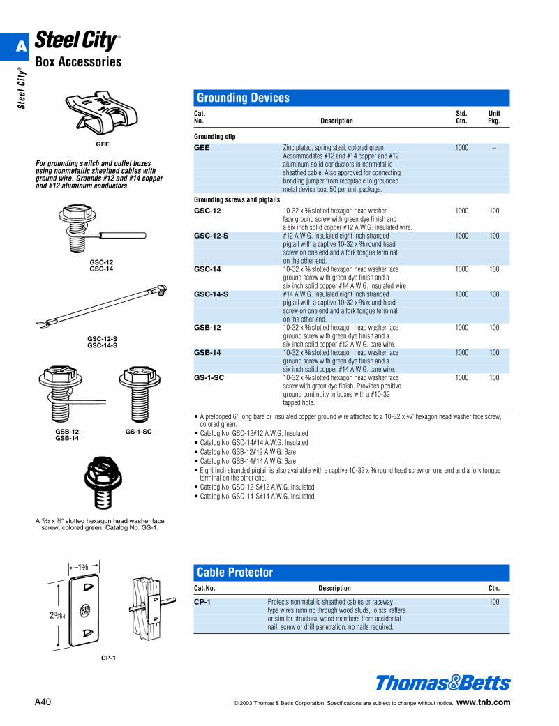
Grounding DevicesCat. Std. UnitNo. Description Ctn. Pkg.
Grounding clip
GEE Zinc plated, spring steel, colored green 1000 –Accommodates #12 and #14 copper and #12aluminum solid conductors in nonmetallicsheathed cable. Also approved for connectingbonding jumper from receptacle to groundedmetal device box. 50 per unit package.
Grounding screws and pigtails
GSC-12 10-32 x c slotted hexagon head washer 1000 100face ground screw with green dye finish and a six inch solid copper #12 A.W.G. insulated wire.
GSC-12-S #12 A.W.G. insulated eight inch stranded 1000 100pigtail with a captive 10-32 x c round headscrew on one end and a fork tongue terminalon the other end.
GSC-14 10-32 x c slotted hexagon head washer face 1000 100ground screw with green dye finish and a six inch solid copper #14 A.W.G. insulated wire
GSC-14-S #14 A.W.G. insulated eight inch stranded 1000 100pigtail with a captive 10-32 x c round headscrew on one end and a fork tongue terminalon the other end.
GSB-12 10-32 x c slotted hexagon head washer face 1000 100 ground screw with green dye finish and a six inch solid copper #12 A.W.G. bare wire.
GSB-14 10-32 x c slotted hexagon head washer face 1000 100ground screw with green dye finish and a six inch solid copper #14 A.W.G. bare wire.
GS-1-SC 10-32 x c slotted hexagon head washer face 1000 100screw with green dye finish. Provides positive ground continuity in boxes with a #10-32tapped hole.
• A prelooped 6" long bare or insulated copper ground wire attached to a 10-32 x c" hexagon head washer face screw,colored green.
• Catalog No. GSC-12#12 A.W.G. Insulated• Catalog No. GSC-14#14 A.W.G. Insulated• Catalog No. GSB-12#12 A.W.G. Bare• Catalog No. GSB-14#14 A.W.G. Bare• Eight inch stranded pigtail is also available with a captive 10-32 x c round head screw on one end and a fork tongue
terminal on the other end.• Catalog No. GSC-12-S#12 A.W.G. Insulated• Catalog No. GSC-14-S#14 A.W.G. Insulated
GEE
For grounding switch and outlet boxesusing nonmetallic sheathed cables withground wire. Grounds #12 and #14 copperand #12 aluminum conductors.
GSC-12GSC-14
GSC-12-SGSC-14-S
Cable ProtectorCat.No. Description Ctn.
CP-1 Protects nonmetallic sheathed cables or raceway 100type wires running through wood studs, joists, raftersor similar structural wood members from accidentalnail, screw or drill penetration; no nails required.
CP-1
A
Stee
l Cit
y®