Embed Size (px)
Citation preview

Num. …
Anno XXXIII – Speciale CTA 2015 – Num. 3
___________________ *Corresponding author: Giuseppe Brando, Department of Engineering and Geology, University “G. D’Annunzio”, Chieti-Pescara, Italy Email: [email protected]
International Journal of Earthquake Engineering
METAL SHEAR PANELS FOR SEISMIC PROTECTION OF BUILDINGS: RECENT FINDINGS AND PERSPECTIVES
Gianfranco De Matteis1, Giuseppe Brando2*
1Department of Architecture and Industrial Design “Luigi Vanvitelli”, Second University of Naples, Italy
2Department of Engineering and Geology, University “G. D’Annunzio”, Chieti-Pescara, Italy
SUMMARY: This paper describes recent experimental researches carried out on metal shear panels to be employed as dampers for seismic protection of new and existing buildings. Three typologies of shear panels are presented, which have been conceived with different strategies to mitigate the detrimental effects provoked by buckling phenomena. For each solution, experimental results are provided together with design issues. Also, some remarks on the technological aspects of the devices are highlighted in order to limit the adoption of bad details that could jeopardize the structural performance of the system. In the whole, the obtained outcomes provide interesting information opening new frontiers in the field of research on dissipative metal shear panels. KEYWORDS: Metal Shear Plates, Pure Aluminium Shear Panels (PASPs), Buckling Inhibited Shear Panels (BISPs), Perforated Shear Plates (PSPs), Experimental tests
1. INTRODUCTION
In order to satisfy the performance levels commonly required by codes and provisions, a large amount of research was conducted, over the second half of the last century until today, for developing innovative earthquake-resistant systems aiming at improving the seismic performance of structures while keeping either construction or retrofitting costs reasonable. Therefore, the “response control” methodology was developed as alternative to the “traditional” one. The former is based on controlling and limiting the dynamic effects on the structural elements by means of added special devices [Brando et al., 2015]. Contrarily, the “traditional” design methodology exploits the ductility resources of sections and connections [Giugliano et al., 2010, Montuori et al., 2014a], leading to the seismic input dissipation by means of plastic hinges developing. For the response control methodology, different approaches can be distinguished, namely Active Control, Semi-Active Control and Passive Control [Soong and Dargush, 2007]. With particular regard to Passive Control, this approach consists in designing buildings in order to dissipate energy by supplemental damping mechanisms and/or in limiting the transmission of seismic energy to the main structure by decoupling the structure movements the ground shacking. Supplemental damping systems are based on the use of special devices, also known as dampers. They are arranged in the structure and are designed in order to start to dissipate energy by hysteretic [De Matteis et al., 2009], friction [Montuori et al., 2014b] or viscous

G. De MATTEIS and G. BRANDO
6
mechanisms as soon as the structure is shaken, hence reducing its overall dynamic response. The advantages in using dampers may be synthetically listed as follows [Christopoulos and Filiatrault, 2007]: (i) They may be designed and arranged in the construction in order to conveniently change both the damping and the dynamic features of the structure, also reducing possible non regularities; (ii) they may be conceived to dissipate energy under low movements of the structure so that their protective function is activated when the other elements are still in the elastic fields; (iii) after a strong ground motion event, they can be inspected and conveniently replaced. Among the existing dampers, in recent decades, dissipative metal shear panels have collected an increasingly wide consensus. A shear metal panel is generally made of a metal plate working in shear connected to a surrounding steel frame by means of bolted and/or welded connections. The frame has the task of delivering the forces from the primary members of the protected structure to the plate. This type of function can be carried out throughout a direct connection of the panels to the structure (Full-Bay or Partial-Bay configurations; Figs. 1a and 1b) - this leading to the concept of Metal Plate Shear Walls- or by way of steel braces (Bracing Type configuration; Fig. 1c). Apart from the high in-plane stiffness, that allows to solve easily some critical issues related to the lateral deformability of buildings, in particular when they are made of steel moment resisting frames, one of the main prerogatives of shear panels is the easiness in controlling the shear resistance. In fact, unlike the more traditional braced frames, the use of extremely thin elements is made possible by a stable post-buckling behaviour due to the onset of "tension field" type resisting mechanisms [Shishkin et al., 2009].
a) b) c)
Figure 1. Metal Shear Panels arrangements in a frame: (a) Full-Bay configuration; (b) Partial-Bay configuration and (c) Bracing Type configuration. Source: [De Matteis et al., 2007]
Furthermore, even in presence of reduced thicknesses, the possibility of combining the base plate with other elements – for example, transversal stiffeners - allows the control of the level of demand leading to buckling phenomena as well as to mitigate possible pinching effects producing detriment on the hysteretic cycles. Significant research efforts have been addressed to the definition of innovative metal shear panels conceived in order to provide convenient solutions able to comply with the several demands posed for their employment in seismic prone zone. In this paper, three typologies of shear panels, investigated by the authors in the last ten years, are presented. These are the so called Pure Aluminium Shear Panels (PASPs), Buckling Inhibited Shear Panels (BISPs), Perforated Shear Plates (PSPs), which differentiate each other because of the alternative strategies undertaken to mitigate the detrimental effects that may be provoked by buckling phenomena, as well as to activate the dissipative capacity of the base plate already for low shear strain demands. In particular, full-scale experimental investigations

INGEGNERIA SISMICA – INTERNATIONAL JOURNAL OF EARTHQUAKE ENGINEERING
7
are shown with the aim of giving a general overview on the structural performance parameters that characterize the response of the studied panel typologies and to put in evidence pros and cons of the proposed solutions. Moreover, for each typology, information about technological details to be adopted are provided, in order to minimize possible issues that could arise for a bad set-up of the proposed systems.
2. PURE ALUMINIUM SHEAR PANELS (PASPS)
2.1 General
PASPs fall in the family of shear panels made of low yield stress (LYS) metals. Their use, joined to a rigorous application [Longo et al., 2009] of the capacity design criteria, could be definitely effective for the seismic upgrading of new and existing buildings. During the nineties, LYS panels found a large success in Asia, where a steel with low carbon content characterized by a yield stress of 120 MPa and a ductility of 50% (Nakashima, 1995) was used. The idea of employing the aluminium alloy EN-AW 1050A H24, which is an almost pure aluminium, came from the fact that the steel described above is not produced and commercialised in both the European and North-American market. On the other hand, the considered alloy seems to be the perfect surrogate solution, as it can be characterized, if properly treated (see Section 2.2), by a very low yield stress and a high ductility. In this Section, experimental and numerical studies on two types of PASPs are presented. They have been conceived for being installed in the structures according to a “full-bay” and a “bracing type” configuration, respectively.
2.2 The mechanical features obtained downstream the applied heat treatment process
In order to minimize the conventional yield stress and, simultaneously, to maximize the ductility, the used EN-AW 1050A H24 was subjected to an annealing process carried out by means of four consecutive phases of heating at 150 °C, 230 °C, 280 °C and 330°C, each one characterized by a duration of four hours. The applied process allowed a transformation of the base material according to the following three successive phases: i) “Crystal Recovery”, aimed at changing the internal structural equilibrium by acting on the ties between the grains; ii) “Re-Crystallization”, which serves to establish and to develop new internal grains, to annul residual stresses and to diminish the elastic strength; iii) “Grains Enlargement”, that complete the “Re-Crystallization” phase, giving back an alloy with lower elastic strength and higher ductility [De Matteis et al, 2012]. At the end of the annealing process described above, the elastic strength of the base material significantly diminished, as it can be observed in Tab. 1, where the original material is compared with the treated one in terms of mechanical features. Moreover, the ductility increased of about eight times, this making the studied material particularly apt for fabricating shear panels to be used as dampers.
Table 1. Mechanical features of the not treated and the treated EN-AW 1050A H24 aluminium alloys
Material f0.2
[MPa] fu
[MPa] u
[%] E
[MPa] E/f0.2 =fu/f0.2
Not treated EN-AW 1050A H24 alloy
60 120 5 70000 1166 2.00
Treated EN-AW 1050A H24 alloy
20 65 40 70000 3500 3.25

G. De MATTEIS and G. BRANDO
8
The original value of the ultimate strength of the material (120 MPa) was lowered to 65 MPa, providing a kinematic hardening factor equal to 3.25 for the heat treated alloy. Nevertheless, some uni-axial tests carried out in the cyclic field on a plate made of the treated alloy, for which buckling phenomena were restrained by an external steel jacketing (Fig. 2a), put in evidence that the ultimate strength can increase up to a value of 80 MPa ( =4.00) due to the isotropic hardening (Fig. 2b), which is usually higher for low yield stress metals and that plays a very important role when the material is used for producing structural elements that have to participate to the inelastic cyclic response of the whole structure [Bosco et al., 2015].
2.3 Experimental tests on “Full-Bay” Pure Aluminium Shear Panels
Full bay shear panels have been investigated by performing cyclic tests under shear loads on four different specimen configurations.
a) b)
Figure 2. Cyclic Tests on the heat treated alloy: (a) the tested specimen; (b) isotropic hardening effectson the compression/tensile stress.
For three of the studied coupons (which henceforth are labelled as shear panels “type B”, “type F” and “type G”), welded longitudinal and transversal rectangular stiffeners, with depth of 60 mm and thickness of 5 mm. were used. Instead, for the fourth specimen, named “type H”, steel channel shaped ribs, bolted to the basic aluminium plate, were considered. Finally, for comparison purpose, specimens “type B” and panel “type F” made of the AW 5154A aluminium alloy, which is more commonly used, were considered. The selected configurations of the tested panels are described in Fig. 3, where the slenderness parameter b/t (depth/thickness) of each sub-panel portion determined by the presence of stiffeners is reported. It is to be noted that panel “type F” has the same slenderness panel “type G” (excluding the corner portions), but different ribs arrangements. In fact, unlike the other panel typologies, panel “type F” has stiffeners welded on the base plate in a staggered manner on the two opposite faces of the shear plate. In Fig. 4 the testing apparatus used for the quasi-static cyclic tests is shown. The studied panels were inserted in a steel articulate frame and connected to the perimeter elements by means of friction high-strength bolts (Fig. 4a). The external load was applied at the top beam of the frame by means of a servo-hydraulic actuator. The actuator was connected to a very rigid lateral support steel frame used as reaction frame (Fig. 4b). The results of the experimental tests are provided in Fig. 5 in terms of hysteretic cycles and in Fig. 6 in terms of hardening ratio (a), secant global stiffness (b) and equivalent viscous damping
1st cycle2nd cycle3rd cycle

INGEGNERIA SISMICA – INTERNATIONAL JOURNAL OF EARTHQUAKE ENGINEERING
9
ratio (c) vs. shear deformation (), consistently with the definition given in Fig. 6d. Based on the obtained results tested specimens pointed out a very high ductility and a good structural performance in terms of strength, stiffness and dissipative capacity. This proved that the considered systems can be usefully adopted as passive seismic protection device. Nevertheless, two negative behaviours were observed during the tests, with evident repercussions on the panels response. In fact, some local buckling phenomena arose on the bottom panel portions in the corners, because of the vertical forces produced by the moment given by the shear force applied on the top beam of the perimeter frame, which was characterized by a lever arm equal to the height of the panel. This type of secondary effects produced some slipping phenomena (more evident for low shear strain) values that limited the performance of the systems giving back a strong reduction of equivalent viscous damping at a shear strain of about 2%. Also due to the above described phenomena, it was noted that each panel exhibited its better dissipative behaviour only for very high inter-story drift demands (6%:7%) (equivalent viscous damping factor of around 30%), which are usually out of the range within which the studied shear panels should work. The experimental tests described above have been used in order to construct reliable FEM models [De Matteis et al, 2008] that were used in order to carry out parametric numerical analyses, which allowed to define design curves and to provide indication about the optima configuration of stiffeners depending on the panels slenderness [Formisano et al., 2006].
panel type B (b/t=100) panel type F (b/t=50)
panel type G (b/t=50-25) panel type H (b/t=50)
Figure 3. The tested “full-bay” pure aluminium shear panels

G. De MATTEIS and G. BRANDO
10
Figure 5. Hysteretic cycles provided by the tested full bay shear panels
- 4 0
- 3 0
- 2 0
- 1 0
0
1 0
2 0
3 0
4 0
- 0 .1 5 - 0 .1 2 - 0 .0 9 - 0 .0 6 - 0 . 0 3 0 0 . 0 3 0 . 0 6 0 . 0 9
s h e a r s t r a i n ( m m / m m )
sh
ea
r s
tre
ss
(M
Pa
P U R E A L U M I N I U M S H E A R P A N E LC O N F I G U R A T I O N T Y P E F
- 5 0
- 4 0
- 3 0
- 2 0
- 1 0
0
1 0
2 0
3 0
4 0
5 0
- 0 . 1 -0 .0 8 - 0 .0 6 - 0 . 0 4 -0 . 0 2 0 0 .0 2 0 . 0 4 0 . 0 6
s h e a r s t r a i n ( m m / m m )
sh
ea
r s
tre
ss
(M
Pa
)
P U R E A L U M I N IU M S H E A R P A N E LC O N F I G U R A T I O N T Y P E G
- 5 0
- 4 0
- 3 0
- 2 0
- 1 0
0
1 0
2 0
3 0
4 0
5 0
- 0 . 1 2 - 0 .0 9 - 0 . 0 6 - 0 . 0 3 0 0 . 0 3 0 . 0 6 0 .0 9
s h e a r s t r a i n ( m m / m m )
sh
ea
r s
tre
ss
(M
Pa
P U R E A L U M IN IU M S H E A R P A N E LC O N F IG U R A T IO N T Y P E H
- 5 0
- 4 0
- 3 0
- 2 0
- 1 0
0
1 0
2 0
3 0
4 0
5 0
6 0
- 0 .1 5 -0 .1 2 -0 .0 9 -0 .0 6 - 0 .0 3 0 0 .0 3 0 .0 6 0 .0 9 0 .1 2 0 .1 5
s h e a r s t ra in (m m /m m )
shea
r st
ress
(M
Pa)
a)
b)
Figure 4. The testing apparatus for the “full bay” shear panels

INGEGNERIA SISMICA – INTERNATIONAL JOURNAL OF EARTHQUAKE ENGINEERING
11
2.4 Experimental tests and numerical analysis on “bracing-type” Pure Aluminium Shear Panels
The above experimental tests highlighted that shear panels conceived in a full bay type configuration may present some critical issues when they are subjected to low-middle shear demands, whereas they are able to provide a significant dissipative capacity for very high values of shear strains. In order to increase the local deformation of shear panels for reduced inter-story drifts demands of the primary framed structure, exploiting the high ductility of the base material, the bracing type configuration was proposed.
a) b)
c) d)
Figure 6. Comparison among tested panels (interpolation curves) in terms of hardening ratio (a), secant global stiffness (b) and equivalent viscous damping ratio(c); definition of parameters (d).
It was characterised by reduced dimensions of shear panels with respect to the surrounding structural frame in which panels should be installed, so to increase the ratio between the shear deformation of the panel and the developed inter-story drift of the frame. Moreover, shear panels connected to the structure by means of steel braces allow to avoid those detrimental secondary effects described for the full by typology, when the shear force lead to a bending moment development. Four cyclic tests were carried out under quasi-static cyclic loads. The tested shear panels, which henceforth will be indicate as “type 1”, “type 2”, “type 3” and “type 4” were characterized by global dimensions of 500 by 500 mm and a plate thickness of 5 mm (Fig. 7). The base material was the same considered for the “full-bay” specimens. Rectangular ribs having a depth of 60 mm and a thickness of 5mm were applied on the base plate. They have been positioned on both faces of the base plate and arranged in order to comply
0
1
2
3
4
0% 2% 4% 6% 8% 10% 12% 14% 16% 18% 20% 22% 24% 26% 28%
shear strain
ma
x/
02
AW 1050A-Panel type BAW 1050A-Panel type FAW 5154A-Panel type BAW 5154A-Panel type FAW 1050A-Panel type GAW 1050A-Panel type H
0
2000
4000
6000
8000
10000
12000
14000
16000
0% 2% 4% 6% 8% 10% 12% 14% 16% 18% 20% 22% 24% 26% 28%
shear strain
Gse
c (M
pa
)
AW 1050A-Panel type BAW 1050A-Panel type FAW 5154A-Panel type BAW 5154A-Panel type FAW 1050A-Panel type GAW 1050A-Panel type H
0%
5%
10%
15%
20%
25%
30%
35%
0% 2% 4% 6% 8% 10% 12% 14% 16% 18% 20% 22% 24% 26% 28%
shear strain
eq
AW 1050A-Panel type BAW 1050A-Panel type FAW 5154A-Panel type BAW 5154A-Panel type FAW 1050A-Panel type GAW 1050A-Panel type H
s
FG
E
E
sFE
S
Deq
S
sec
4
18
1

G. De MATTEIS and G. BRANDO
12
with the rules given by Eurocode 9 [EN1999-1-1, 2007] in order to postpone shear buckling of the plate in the inelastic field [Höglund, 1997]. The selected stiffeners arrangement lead to slenderness ratio b/t (where b is the distance between two consecutive stiffeners and t is the base plate thickness) equal to 100 (no intermediate stiffeners), 50, 33.3 and 25 for shear panel “type 1”, “type 2”, “type 3” and “type 4” respectively. The four specimens were inserted into a pin jointed steel frame and were connected to its channel elements along their edge by means of tightened steel bolts. A MTS810 universal machine was used in order to load the investigated shear panels along one of the two diagonals, according to the load protocol reported in Fig. 8. In Fig. 9, the hysteretic cycles given back by tests, expressed in terms of diagonal force-diagonal displacement, are provided.
panel “type 1” (b/t=100) panel “type 2” (b/t=50)
panel “type 3” (b/t=33) panel “ type 4” (b/t=25)
Figure 7. The tested “bracing-type” pure aluminium shear panel configurations
a) b)
Figure 8. Applied displacement history (a) and loading scheme (b)
-80
-60
-40
-20
0
20
40
60
80
0 1000 2000 3000 4000Time [s]
Dis
plac
emen
t [m
m]

INGEGNERIA SISMICA – INTERNATIONAL JOURNAL OF EARTHQUAKE ENGINEERING
13
The cyclic responses appeared to be appealing from the dissipative point of view due to the large ductility offered by the devices. Nevertheless, it is evident that two different types of hysteretic performances were obtained. The first, typical of panels usually classified as semi-compact and characterizing both shear panels “type 1” and “type 2”, gave back hysteretic cycles affected by pinching effects in the inelastic field. The latter, which are related to both shear panel “type 3” and “type 4”, allowed to have, despite of some local buckling phenomena observed during tests, large cycles and, therefore, to get a larger dissipative capacity. Therefore panels “type 3” and “type 4” behave a compact shear panels, also in accordance with the fact that the ultimate shear strength did not result deteriorated with respect to the theoretical one offered by a pure shear resisting mechanism. In fact, considering that shear areas equal to A3=4900mm2 and A4=5500mm2 are detectable for panels “type 3” and “type 4” respectively, the ultimate shear strengths (Vu,3 and Vu, 4) due to a pure shear mechanism (Eqs. (1) and (2)) are equal to the maximum strength read on the hysteretic cycles.
Nf
AV uu 198031
333, (1)
Nf
AV uu 222279
344, (2)
Further consideration may be fruitfully obtained by the comparison of the investigated panel types in terms of energy dissipation, hardening ratio, secant global stiffness and equivalent viscous damping ratio, according to the definition reported in Fig. 6d. In Figs 10 and 11 these synthetic parameters, are expressed as a function of the applied shear strain value for semi-compact and compact shear panels respectively. In the same figures the interpolation curves of the above magnitudes, expressed by means of polynomial laws, are also depicted. In detail, as far as the semi-compact panels are concerned, shear panel “type 2” provided a better dissipative behaviour than panel “type 1”, due to both the larger cycles and resistant capacity, as it is detectable by the comparison carried out in terms of cumulated dissipated energy. This is testified also by the higher equivalent viscous damping factor (45% versus 37%). However, panel configuration “type 1” exhibited higher values of both hardening ratio and secant shear stiffness at collapse. In fact, the higher strength presented by panel “type 2”, due to to the larger shear area including part of the stiffeners, provoked a higher engagement of the plate-to-perimeter frame connection and, thus, an anticipated failure of the system. Comparison between shear panels “type 3” and “type 4” allows to state that the two panels are almost characterized by the same type of performances in terms of cumulated dissipated energy, equivalent viscous damping factor and secant stiffness (Fig. 11). They presented an important response from the dissipative point of view, giving back equivalent viscous damping factor equal to about 50%. Among the two panel typologies, the first results therefore the most convenient to be used, as it requires a minor quantity of material to be employed. The only differences may be observed for the comparison carried out in terms of hardening ratio which put in evidence that, due to a larger shear area, panel “type 4” presented a shear strength higher than panel “type 3”. As explained also for the comparison of panels “type1” and “type 2”, this rebounds on the performances of the connecting system placed on the edges of the panels which is more stressed for panel “type 4”, entailing a quicker decay of its strength for very high shear strength demands.

G. De MATTEIS and G. BRANDO
14
a) b)
c) d)
Figure 9. Hysteretic cycles: “type 1” (a), “type 2” (b), “type 3” (c) and “type 4”
a) b)
c) d)
Figure 10. Results for semi-compact panels “type 1” and “type 2”: (a) cumulated dissipated energy, (b) hardening ratio, (c) secant shear stiffness, (d) equivalent viscous damping factor
-250-200-150-100-50
050
100150200250
-80 -60 -40 -20 0 20 40 60 80Displacement [mm]
For
ce[k
N]
-250-200-150-100-50
050
100150200250
-80 -60 -40 -20 0 20 40 60 80Displacement [mm]
For
ce [
kN]
-250-200-150-100-50
050
100150200250
-80 -60 -40 -20 0 20 40 60 80Displacement [mm]
For
ce[k
N]
-250-200-150-100-50
050
100150200250
-80 -60 -40 -20 0 20 40 60 80Displacement [mm]
For
ce[k
N]
0
50
100
150
200
250
300
0 2 4 6 8 10 12 14Shear Strain [%]
Cum
ulat
ed d
issi
pate
d E
nerg
y[kN
m]
"type 1"
"type 2"
Poli. ("type 1")
Poli. ("type 2")
0.00
1.00
2.00
3.00
4.00
5.00
6.00
7.00
8.00
0 2 4 6 8 10 12 14Shear Strain [%]
Har
deni
ng r
atio
0.2
"type 1"
"type 2"
Poli. ("type 1")
Poli. ("type 2")
0
5
10
15
20
25
30
35
40
45
50
0 2 4 6 8 10 12 14Shear Strain [%]
Sec
ant S
tiff
ness
[kN
/mm
]
"type 1"
"type 2"
Poli. ("type 1")
Poli. ("type 2")
0
0.1
0.2
0.3
0.4
0.5
0.6
0 2 4 6 8 10 12 14Shear Strain [%]
Equ
ival
ent v
isco
us d
ampi
ng f
acto
r
"type 1"
"type 2"
Poli. ("type 1")
Poli. ("type 2")

INGEGNERIA SISMICA – INTERNATIONAL JOURNAL OF EARTHQUAKE ENGINEERING
15
It must be noted that the four shear panels exhibited unexpected slipping phenomena for very small shear forces, due to the presence of internal residual stresses produced by the welding process of stiffeners. In fact, some experimental tests reported in [De Matteis et al., 2012] proved that these residual stresses could be comparable to the nominal yield stress, and could provoke hardening effects leading to an increase of yielding strength of about 10 MPa, which corresponds to about 50% of the original value for not-welded specimen. However, it is to pointed out that the detrimental effects due to residual stress does not influence significantly the hysteretic response for medium-high shear demands. As for the “full-bay” typology, also for the studied “bracing type” shear panels the proposed experimental tests served to develop FEM numerical models. These models have been profitably used to check the stress states, the deformed shapes and the main resistant mechanisms of the analysed shear panel typology for different shear strain demands. Moreover, the obtained numerical models have been used in order to implement parametrical numerical analyses and to provide design curves and formulations [Brando and De Matteis, 2014].
a) b)
c) d)
Figure 11. Results for semi-compact panels “type 1” and “type 2”: (a) cumulated energy, (b) hardening ratio, (c) secant shear stiffness, (d) equivalent viscous damping factor
3. BUCKLING INHIBITED PURE ALUMINIUM SHEAR PANELS (BIPASPS)
3.1 General
When low yield strength shear panels are used, one of the main critical issues is that very thin plate are often necessary, even in presence of a base material characterized by a low yield stress point. This could entail economical and technological counter-indications, as well as technological problems related to an excessive use of weld for the transversal ribs. As a
0
50
100
150
200
250
300
0 2 4 6 8 10 12 14Shear Strain [%]
Cum
ulat
ed d
issi
pate
d E
nerg
y[kN
m]
"type 3"
"type 4"
Poli. ("type 3")
Poli. ("type 4")
0.00
1.00
2.00
3.00
4.00
5.00
6.00
7.00
8.00
0 2 4 6 8 10 12 14Shear Strain [%]
Har
deni
ng r
atio
0.2
"type 3"
"type 4"
Poli. ("type 3")
Poli. ("type 4")
0
5
10
15
20
25
30
35
40
45
50
0 2 4 6 8 10 12 14Shear Strain [%]
Seca
nt S
tiff
ness
[kN
/mm
]
"type 3"
"type 4"
Poli. ("type 3")
Poli. ("type 4")
0
0.1
0.2
0.3
0.4
0.5
0.6
0 2 4 6 8 10 12 14Shear Strain [%]
Equ
ival
ent v
isco
us d
ampi
ng f
acto
r
"type 3"
"type 4"
Poli. ("type 3")
Poli. ("type 4")
G. De MATTEIS and G. BRANDO
16
convenient alternative to the use of stiffened shear panels, recently, the authors proposed a new type of shear panel, based on the concept of buckling phenomena inhibition [Brando et al. 2013]. In particular, two different technological solutions for restraining the out-of-plane deformations of the system have been proposed. They are based on the use of not connected steel elements, able to restrain the first and more important critical modes of the panel. These elements react only in the direction perpendicular to the base plate, leaving the base plate work according to a pure shear resistant mechanism. In the following, the main results of an experimental campaign carried out on two selected configurations are shown. The first is a partially buckling inhibited solution, for which the out-of-plane displacement that could develop along the two diagonal of the panel are restrained. The latter is a totally buckling inhibited shear panels, for which the out-of-plane displacements are restrained for the whole plate. Both the investigated solution are conceived to work in a bracing-type configuration. Moreover, in order to prove the effectiveness of the proposed solution, the performance of the tested panel is compared with the one obtained downstream the previous presented experimental activity carried out on bracing type pure aluminium shear panels.
3.2 The experimental behaviour
In Fig. 12 the two proposed buckling inhibited shear panels are shown. They were obtained by inserting a 5 mm thick pure aluminium shear plate in the same square articulated steel frame used for the experimental tests carried out on the PASP typology. For the first solution (p-BISP, acronym of “partially Buckling Inhibited Shear Panels”), two cross shape 10mm thick/140 mm wide steel elements were used for inhibiting the first four critical modes of the base plate. These were arranged on both side oF the base plate along the two diagonal. In the second technological solution (“t-BISP”, acronym of “totally Buckling Inhibited Shear Panels”), two octagonal steel plates were mounted for restraining the out-of-plane displacements of the whole plate in shear. In both cases, lexan sheeting were employed in order to reduce the friction between the parts. The hysteretic behaviour of the two panels are shown in Fig. 13. The obtained large hysteretic cycles prove the high dissipative capacity of the devices, guaranteed, also for high shear demands, by a substantial absence of significant pinching effects. However, it is to be underlined that the t-BIPSP configuration behaved in a more performing way, as it was not influenced by the secondary buckling phenomena that, contrarily, developed for the p-BIP solution. Furthermore, larger cycles given from the t-BIP configuration were due to the confinement effects produced by the more extended contact of the restraining plates. The panels behaviour can be considered approximately elastic up to a diagonal displacement of ±0.50 mm (shear strain of 0.1%). After this threshold, an inelastic behaviour was registered. The first buckling phenomena slightly arose for a shear strain demand of ±0.66% (diagonal displacement of ±3.00 mm) on the not inhibited portions of the p-BIP configuration. Nevertheless, these did not lead to any significant effects on the revealed hysteretic cycles. On the contrary these instabilities were more eye-catching for a shear strain of 2.20%, (Fig. 14.a), starting to influence the hysteretic response with slight pinching effects (Fig. 14.b) after the first cycles. On the other hand, at this shear demand, no particular degrading phenomena were measured for the t-BIP configuration and the corresponding hysteretic cycles did not present any particular detrimental effects.

INGEGNERIA SISMICA – INTERNATIONAL JOURNAL OF EARTHQUAKE ENGINEERING
17
a) b)
Figure 12. The studied (a) Partially Buckling Inhibited Panel (p-BIP) and (b) Totally Buckling Inhibited Panel (t-BIP)
a) b)Figure 13. The obtained hysteretic cycle: a) “p-BIP” and b) “t-BIP”
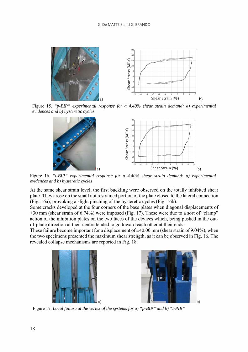
When a shear strain demand of ±4.40% (diagonal displacements of ±20 mm) was attained, relevant buckle waves were noticed in the extent of the not restrained plate portions of panel type “p-BIP” (Figure 15.a). Nevertheless, the shape of the hysteretic cycles was not still influenced by these phenomena (Figure 15.b), this proving that the influence of the higher critical modes is less important for higher shear demands.
a) b)
Figure 14. “p-BIP” experimental response for a 2.20% shear strain demand: a) experimental evidences and b) hysteretic cycles
‐18 ‐15 ‐12 ‐9 ‐6 ‐3 0 3 6 9 12 15 18‐80
‐60
‐40
‐20
0
20
40
60
80
ShearStrain(% )
ShearStress(MPa)
‐18 ‐15 ‐12 ‐9 ‐6 ‐3 0 3 6 9 12 15 18‐80
‐60
‐40
‐20
0
20
40
60
80
ShearStrain(% )
ShearStress(MPa)
‐2.5 ‐2.0 ‐1.5 ‐1.0 ‐0.5 0.0 0.5 1.0 1.5 2.0 2.5‐80
‐60
‐40
‐20
0
20
40
60
80
ShearStrain(%)
ShearStress(MPa)
G. De MATTEIS and G. BRANDO
18
a) b)
Figure 15. “p-BIP” experimental response for a 4.40% shear strain demand: a) experimental evidences and b) hysteretic cycles
a) b)
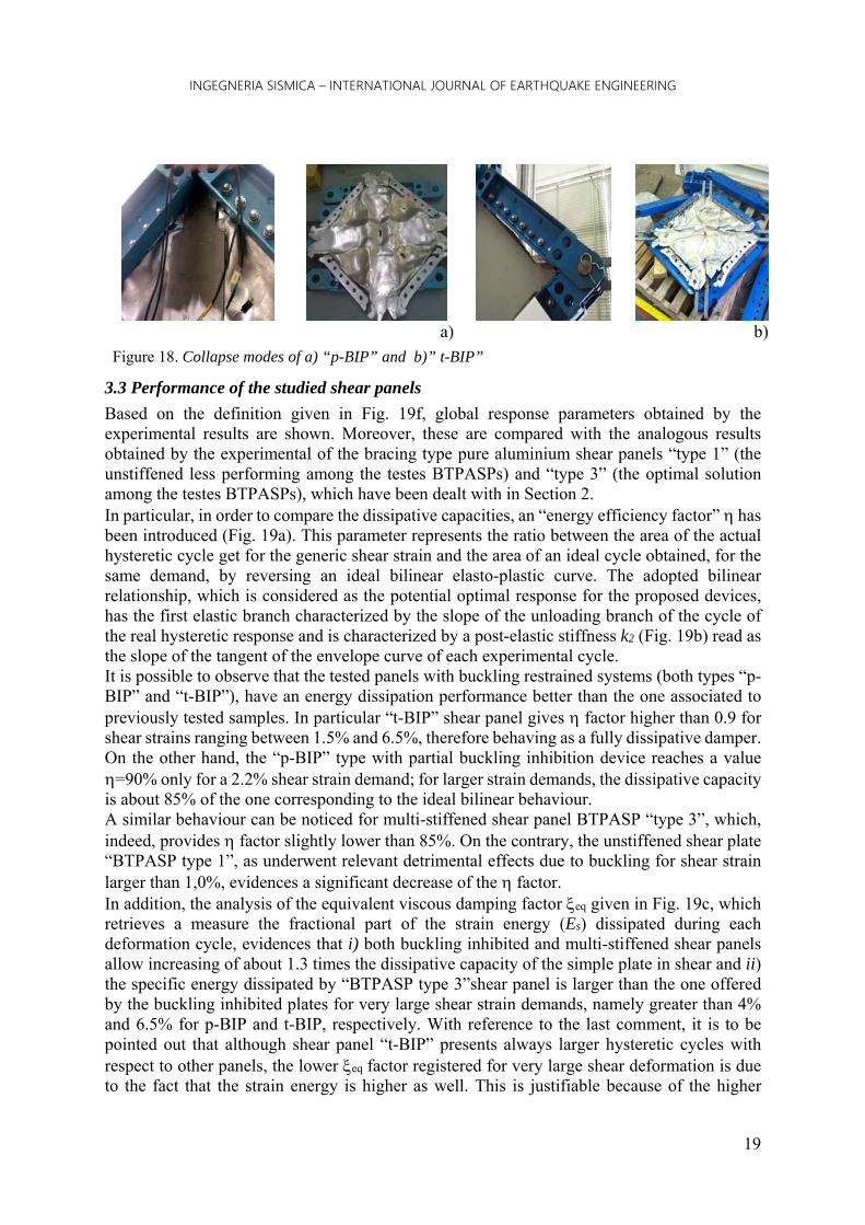
Figure 16. “t-BIP” experimental response for a 4.40% shear strain demand: a) experimental evidences and b) hysteretic cycles
At the same shear strain level, the first buckling were observed on the totally inhibited shear plate. They arose on the small not restrained portion of the plate closed to the lateral connection (Fig. 16a), provoking a slight pinching of the hysteretic cycles (Fig. 16b). Some cracks developed at the four corners of the base plates when diagonal displacements of ±30 mm (shear strain of 6.74%) were imposed (Fig. 17). These were due to a sort of “clamp” action of the inhibition plates on the two faces of the devices which, being pushed in the out-of-plane direction at their centre tended to go toward each other at their ends. These failure become important for a displacement of ±40.00 mm (shear strain of 9.04%), when the two specimens presented the maximum shear strength, as it can be observed in Fig. 16. The revealed collapse mechanisms are reported in Fig. 18.
a) b)
Figure 17. Local failure at the vertex of the systems for a) “p-BIP” and b) “t-PIB”
‐5 ‐4 ‐3 ‐2 ‐1 0 1 2 3 4 5‐80
‐60
‐40
‐20
0
20
40
60
80
ShearStrain(%)
ShearStress(MPa)
‐5 ‐4 ‐3 ‐2 ‐1 0 1 2 3 4 5‐80
‐60
‐40
‐20
0
20
40
60
80
ShearStrain(%)
ShearStress(MPa)
INGEGNERIA SISMICA – INTERNATIONAL JOURNAL OF EARTHQUAKE ENGINEERING
19
a)
b)
Figure 18. Collapse modes of a) “p-BIP” and b)” t-BIP”
3.3 Performance of the studied shear panels
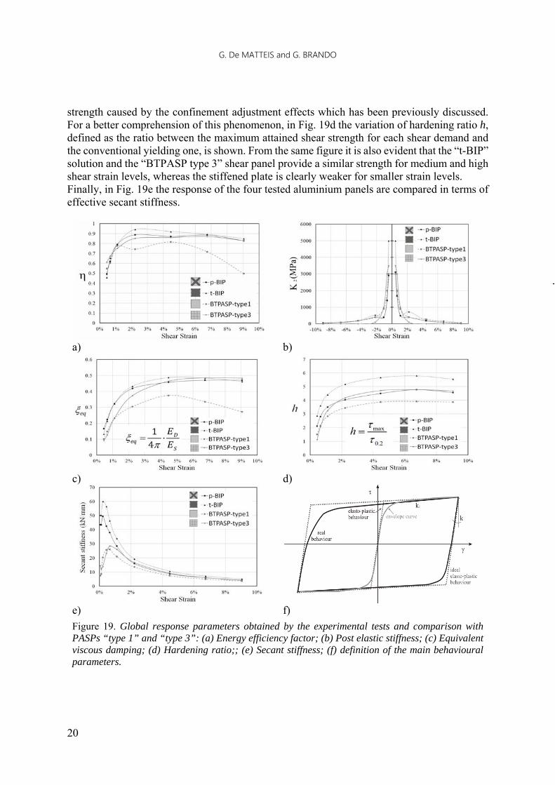
Based on the definition given in Fig. 19f, global response parameters obtained by the experimental results are shown. Moreover, these are compared with the analogous results obtained by the experimental of the bracing type pure aluminium shear panels “type 1” (the unstiffened less performing among the testes BTPASPs) and “type 3” (the optimal solution among the testes BTPASPs), which have been dealt with in Section 2. In particular, in order to compare the dissipative capacities, an “energy efficiency factor” has been introduced (Fig. 19a). This parameter represents the ratio between the area of the actual hysteretic cycle get for the generic shear strain and the area of an ideal cycle obtained, for the same demand, by reversing an ideal bilinear elasto-plastic curve. The adopted bilinear relationship, which is considered as the potential optimal response for the proposed devices, has the first elastic branch characterized by the slope of the unloading branch of the cycle of the real hysteretic response and is characterized by a post-elastic stiffness k2 (Fig. 19b) read as the slope of the tangent of the envelope curve of each experimental cycle. It is possible to observe that the tested panels with buckling restrained systems (both types “p-BIP” and “t-BIP”), have an energy dissipation performance better than the one associated to previously tested samples. In particular “t-BIP” shear panel gives factor higher than 0.9 for shear strains ranging between 1.5% and 6.5%, therefore behaving as a fully dissipative damper. On the other hand, the “p-BIP” type with partial buckling inhibition device reaches a value =90% only for a 2.2% shear strain demand; for larger strain demands, the dissipative capacity is about 85% of the one corresponding to the ideal bilinear behaviour. A similar behaviour can be noticed for multi-stiffened shear panel BTPASP “type 3”, which, indeed, provides factor slightly lower than 85%. On the contrary, the unstiffened shear plate “BTPASP type 1”, as underwent relevant detrimental effects due to buckling for shear strain larger than 1,0%, evidences a significant decrease of the factor. In addition, the analysis of the equivalent viscous damping factor eq given in Fig. 19c, which retrieves a measure the fractional part of the strain energy (Es) dissipated during each deformation cycle, evidences that i) both buckling inhibited and multi-stiffened shear panels allow increasing of about 1.3 times the dissipative capacity of the simple plate in shear and ii) the specific energy dissipated by “BTPASP type 3”shear panel is larger than the one offered by the buckling inhibited plates for very large shear strain demands, namely greater than 4% and 6.5% for p-BIP and t-BIP, respectively. With reference to the last comment, it is to be pointed out that although shear panel “t-BIP” presents always larger hysteretic cycles with respect to other panels, the lower eq factor registered for very large shear deformation is due to the fact that the strain energy is higher as well. This is justifiable because of the higher
G. De MATTEIS and G. BRANDO
20
strength caused by the confinement adjustment effects which has been previously discussed. For a better comprehension of this phenomenon, in Fig. 19d the variation of hardening ratio h, defined as the ratio between the maximum attained shear strength for each shear demand and the conventional yielding one, is shown. From the same figure it is also evident that the “t-BIP” solution and the “BTPASP type 3” shear panel provide a similar strength for medium and high shear strain levels, whereas the stiffened plate is clearly weaker for smaller strain levels. Finally, in Fig. 19e the response of the four tested aluminium panels are compared in terms of effective secant stiffness.
a) b)
c) d)
e) f)
Figure 19. Global response parameters obtained by the experimental tests and comparison with PASPs “type 1” and “type 3”: (a) Energy efficiency factor; (b) Post elastic stiffness; (c) Equivalent viscous damping; (d) Hardening ratio;; (e) Secant stiffness; (f) definition of the main behavioural parameters.

INGEGNERIA SISMICA – INTERNATIONAL JOURNAL OF EARTHQUAKE ENGINEERING
21
Also according to this parameter, the buckling inhibited shear panels were more performing than the conventional ones (shear plate with welded stiffeners). In fact, a larger initial stiffness is retrievable for low shear demands, while in the large strain field the obtained responses are quite comparable to each other. This result is evidently due to the absence of residual stresses and other imperfections which have to be ascribed to welding processes of multi-stiffened shear panels.
4. PERFORATED SHEAR PLATES (PSPS)
4.1 Basis
An alternative fruitful way for obtaining dissipative shear panels may consist in weakening the base plate by removing some of its parts. This type of operation allows to obtain a variation of the internal stress pattern and potentially to mitigate the negative effects generated by possible buckling phenomena. On the other hand it leads to a reduction of the shear strength, also in presence of thick plates, so to accomplish more easily capacity design criteria. A significant literature concerning the use of weakened shear panels has been proposed in the last decade. For example, panels weakened by means of vertical slits were extensively investigated by Hitaka and Matsui [2003] and Pohlenz [2010]; for this type of panel, the shear force acting on the whole system is commuted in a bending mechanism for the plate portions confined by a couple of slits, which undergo large flexural deformations producing a significant dissipative capacity. Vian, Bruneau and Purba [2009] carried out experimental tests on shear panels weakened by holes arranged in a staggered configuration, providing design formulations of the shear strength accounting for the holes diameters and spacing, also considering the influence of the surrounding frame stiffness. Valizadeh et al. [2012] quantified the influence of the holes diameter on the loss of dissipated energy due to the pinching effects on the hysteretic cycles. Furthermore, they highlighted some brittle failures around the perforations when very thin plates are adopted, due to the strong concentration of stresses. Alavi and Nateghi [2013] proved, by experimental tests on 1:2 scaled single-story SPSWs, that perforated diagonally stiffened shear panels allow to obtain the same stiffness of un-ribbed solid panels, with an increase of ductility of more than 14%. In addition, an extension of the design formulation of the shear strength given previously by other Authors was provided, accounting for the diagonal stiffeners contribution. In this framing of research, in the following, the outcomes of two full scale tests carried out on steel perforated shear plates are shown. The main goal is to highlight the most influencing experimental evidences, with particular regard to those phenomena that could reduce the dissipative capacity of the studied devices. 3.2 The experimental tests The two tested perforated shear panels, namely PSP1 (Perforated Shear Panel 1) and PSP2 (Perforated Shear Panel 2), were made of 2.5 mm steel thick plates. Their geometric features are described in Figs. 20a and 20b, where the sizes are expressed in mm. They are characterized by nine perforations arranged in a rectangular pattern, which usually allows better performances of a staggered configuration. Each PSP was connected to the same perimeter articulated frame described for the other panel typologies dealt with in previous Sections. The plate-to-perimeter frame connections were

G. De MATTEIS and G. BRANDO
22
realized again by 8.8 grade M14 steel friction bolts spaced by a pitch of 50 mm. In addition, in order to increase the contact area between the plate and the built up members, double sided internal 10 mm thick plates (two for each edge of the articulated frame) were applied, as it can be seen in Fig. 20.c where the panel is shown during the assemblage process. The experimental set-up was completed by two hinged steel jigs connecting two opposite vertices of the panel to the MTS machine used for carrying out cyclic tests (Fig. 20d). Uniaxial tensile tests on dog bone elements were performed in order to investigate the base material mechanical properties of the plates, showing that the yield stress measured in the lamination direction (about 300 MPa) differs from the one considered perpendicularly (about 270 MPa), whereas no significant differences were revealed in terms of tangential stiffness and ductility. An anisotropic behaviour at yielding was therefore expected.
a) b) c)
d)
Figure 20. The experimental set-up: The plates geometry of a) PSP1 and b) PSP2 panels; one of the specimens (a) during the assemblage process and (b) during the tests
The two tested perforated shear panels were subjected to pseudo-static cyclic tests, considering a diagonal displacements history consistent with the ECCS-CECM Provisions [1985]. The testing apparatus was composed by a mechanical transducer for the measurement of the diagonal displacements (Fig. 20d), by the loading cell installed in the testing machine, as well as by four mechanical LVDT transducers to measure the potential relative motion between the plate edges and the frame elements.
3.3 The obtained experimental evidences
Following an initial phase in which the panels worked in pure shear, the former “global” buckling waves arose in the plate cores centred around the two diagonals, when diagonal displacements of ±5mm (shear strain of ±1.1%; Fig. 21a) and ±2mm (shear strain of ±0.8%; Fig. 21c) were attained, for PSP1 and PSP 2 respectively. Indeed, the amplitude of the diagonal buckling waves described above did not change for the remaining part of the tests. In other words, the applied perforation patterns resulted to be truly effective in modifying the internal stresses and, therefore, in mitigating buckling effects. Nevertheless, for larger diagonal displacements, the activation of higher critical modes was noticed. These modes consisted in lateral-torsional buckling of the panel portions included within the perforations and were due to not constant stresses that produced bending moment in the plane of the plate. These phenomena were clearly visible for a diagonal displacement of 10mm (shear strain of 2.2%) for both PSP1 and PSP2 specimens, as it is shown in Figs. 21b and 21d The main effects consisted in a twisting of the buckled plates portions, with damage significantly cumulated when the number of cycles increased.

INGEGNERIA SISMICA – INTERNATIONAL JOURNAL OF EARTHQUAKE ENGINEERING
23
a) c) c) d)
Figure 21. (a) the shear panel PSP1 at a displacement of ±5.00 mm (shear strain of ±1.1%) aand (b) 10.00 mm (shear strain of ±2.2%); the shear panel PSP2 at a displacement of ±2.00 mm (shear strain of ±0.4%) and (b) 10.00 mm (shear strain of ±2.2%)
For diagonal displacement of 20 mm (shear strain of 4.4%), the local twisting described above became permanently visible, as shown in Figs 22a and 22b. Finally, for higher shear strains, low cycle fatigue provoked some tears closed the perimeter of the holes, provoking some losses of shear strength for diagonal displacements higher than 30 mm (shear strain of 6.7%). In Figs. 22c and 22d the collapses evidenced at a diagonal displacement of 40 mm (shear strain of 9.6%) are shown. The obtained cyclic responses of the two tested shear panels are plotted in Fig. 23 in terms of diagonal displacements vs. diagonal forces. As it can be observed, conspicuous pinching effects were revealed in both the analysed cases.
a) b) b) d)
Figure 22. The experimental evidences registered for the specimens (a) PSP1 and (b) PSP2 at a diagonal displacement of 20 mm (shear strain of ±4.4%). The collapse modes of the (a) PSP1 and (b) PSP2 specimens
a) b)
Figure 23. The obtained hysteretic cycles for specimen (a) PSP1 and (b) PSP2
-100
-75
-50
-25
0
25
50
75
100
-60 -50 -40 -30 -20 -10 0 10 20 30 40 50 60
Dia
gona
l For
ce (k
N)
Diagonal Displacement (mm)
-125
-100
-75
-50
-25
0
25
50
75
100
125
-60 -50 -40 -30 -20 -10 0 10 20 30 40 50 60
Dia
gona
l For
ce (
kN)
Diagonal Displacement (mm)
G. De MATTEIS and G. BRANDO
24
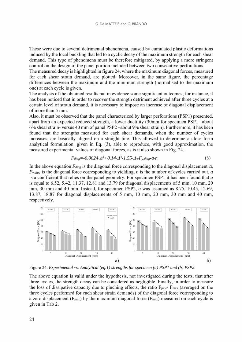
These were due to several detrimental phenomena, caused by cumulated plastic deformations induced by the local buckling that led to a cyclic decay of the maximum strength for each shear demand. This type of phenomena must be therefore mitigated, by applying a more stringent control on the design of the panel portion included between two consecutive perforations. The measured decay is highlighted in figure 24, where the maximum diagonal forces, measured for each shear strain demand, are plotted. Moreover, in the same figure, the percentage differences between the maximum and the minimum strength (normalised to the maximum one) at each cycle is given. The analysis of the obtained results put in evidence some significant outcomes; for instance, it has been noticed that in order to recover the strength detriment achieved after three cycles at a certain level of strain demand, it is necessary to impose an increase of diagonal displacement of more than 5 mm. Also, it must be observed that the panel characterized by larger perforations (PSP1) presented, apart from an expected reduced strength, a lower ductility (30mm for specimen PSP1 –about 6% shear strain- versus 40 mm of panel PSP2 –about 9% shear strain). Furthermore, it has been found that the strengths measured for each shear demands, when the number of cycles increases, are basically aligned on a straight line. This allowed to determine a close form analytical formulation, given in Eq. (3), able to reproduce, with good approximation, the measured experimental values of diagonal forces, as is it also shown in Fig. 24.
Fdiag=-0.00243+0.143-1.55Fy,diag-an (3)
In the above equation Fdiag is the diagonal force corresponding to the diagonal displacement , Fy,diag is the diagonal force corresponding to yielding, n is the number of cycles carried out, a is a coefficient that relies on the panel geometry. For specimen PSP1 it has been found that a is equal to 6.52, 5.42, 11.37, 12.81 and 13.79 for diagonal displacements of 5 mm, 10 mm, 20 mm, 30 mm and 40 mm. Instead, for specimen PSP2, a was assumed as 8.75, 10.45, 12.69, 13.87, 18.87 for diagonal displacements of 5 mm, 10 mm, 20 mm, 30 mm and 40 mm, respectively.
a) b)
Figure 24. Experimental vs. Analytical (eq.1) strengths for specimen (a) PSP1 and (b) PSP2.
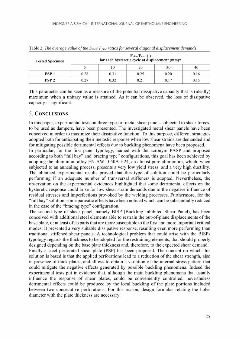
The above equation is valid under the hypothesis, not investigated during the tests, that after three cycles, the strength decay can be considered as negligible. Finally, in order to measure the loss of dissipative capacity due to pinching effects, the ratio Fpinc/ Fmax (averaged on the three cycles performed for each shear strain demands) of the diagonal force corresponding to a zero displacement (Fpinc) by the maximum diagonal force (Fmax) measured on each cycle is given in Tab 2.
0
20
40
60
80
100
120
140
5 10 20 30 40
Dia
gona
l For
ce [
kN]
Diagonal Displacement [mm]
test results
eq. (1)
=20% =17% =32% =35% =41%
0
20
40
60
80
100
120
140
5 10 20 30 40
Dia
gona
l For
ce [
kN]
Diagonal Displacement [mm]
=17% =22% =24% =26% =31%
INGEGNERIA SISMICA – INTERNATIONAL JOURNAL OF EARTHQUAKE ENGINEERING
25
Table 2. The average value of the Fmax/ Fpinc ratios for several diagonal displacement demands
Tested Specimen Fpinc/Fmax (-)
for each hysteretic cycle at displacement (mm)=
5 10 20 30 40
PSP 1 0.28 0.31 0.25 0.20 0.16
PSP 2 0.27 0.32 0.21 0.17 0.15
This parameter can be seen as a measure of the potential dissipative capacity that is (ideally) maximum when a unitary value is attained. As it can be observed, the loss of dissipative capacity is significant.
5. CONCLUSIONS
In this paper, experimental tests on three types of metal shear panels subjected to shear forces, to be used as dampers, have been presented. The investigated metal shear panels have been conceived in order to maximize their dissipative function. To this purpose, different strategies adopted both for anticipating their inelastic response when low shear strains are demanded and for mitigating possible detrimental effects due to buckling phenomena have been proposed. In particular, for the first panel typology, named with the acronym PASP and proposed according to both “full bay” and“bracing type” configurations, this goal has been achieved by adopting the aluminium alloy EN-AW 1050A H24, an almost pure aluminium, which, when subjected to an annealing process, presents a very low yield stress and a very high ductility. The obtained experimental results proved that this type of solution could be particularly performing if an adequate number of transversal stiffeners is adopted. Nevertheless, the observation on the experimental evidences highlighted that some detrimental effects on the hysteretic response could arise for low shear strain demands due to the negative influence of residual stresses and imperfections provoked by the welding processes. Furthermore, for the “full bay” solution, some parasitic effects have been noticed which can be substantially reduced in the case of the “bracing type” configuration. The second type of shear panel, namely BISP (Buckling Inhibited Shear Panel), has been conceived with additional steel elements able to restrain the out-of-plane displacements of the base plate, or at least of its parts that are more susceptible to the first and more important critical modes. It presented a very suitable dissipative response, resulting even more performing than traditional stiffened shear panels. A technological problem that could arise with the BISPs typology regards the thickness to be adopted for the restraining elements, that should properly designed depending on the base plate thickness and, therefore, to the expected shear demand. Finally a steel perforated shear plate (PSP) has been proposed. The concept on which this solution is based is that the applied perforations lead to a reduction of the shear strength, also in presence of thick plates, and allows to obtain a variation of the internal stress pattern that could mitigate the negative effects generated by possible buckling phenomena. Indeed the experimental tests put in evidence that, although the main buckling phenomena that usually influence the response of shear plates, could be conveniently controlled, nevertheless detrimental effects could be produced by the local buckling of the plate portions included between two consecutive perforations. For this reason, design formulas relating the holes diameter with the plate thickness are necessary.

G. De MATTEIS and G. BRANDO
26
In the whole, the presented experimental investigation allows to outline the following main conclusions: the three tested panel typologies represent very interesting and performing solutions to be
used as dampers; design formulations should be provided in the very next future for their use, also to control
the possible negative effects that could be provoked by possible poor technological details; it is necessary to develop a unitary framework that allows the designer to have the
possibility of selecting the most convenient panel typology and details according to the design requirements.
6. ACKNOWLEDGEMENTS
This study was founded in the framing of the ReLUIS Italian research project.
7. REFERENCES
Alavi, E., Nateghi, F. [2013] “Experimental study on diagonally stiffened steel plate shear walls with central perforation”. Journal of Constructional Steel Research, n.89, pp. 9–20.
Bosco, M., Marino, E.M., Rossi, P.P. [2015]. “Modelling of steel link beams of short, intermediate or long length”. Engineering Structures, 84:406–418, ISSN: 0141-0296, doi:10.1016/j.engstruct.2014.12.003
Brando, G., D'Agostino, F., De Matteis, G.[2013]. “Experimental tests of a new hysteretic damper made of buckling inhibited shear panels”. Materials and Structures/Materiaux et Constructions 46 (12) PP. 2121 – 2133.doi: 10.1617/s11527-013-0040-6.
Brando, G., De Matteis, G. [2014]. “Design of low strength-high hardening metal multi-stiffened shear plates”. Engineering Structures 60 PP. 2 - 10 doi: 10.1016/j.engstruct.2013.12.005
Brando, G., D'Agostino, F., De Matteis, G. [2015] “Seismic performance of MR frames protected by viscous or hysteretic dampers”, Structural Design of Tall and Special Buildings, 24 (9), pp. 653-671.
Christopoulos, C., Filiatrault, A. [2007] Principles of Passive Supplemental Damping and Seismic Isolation. IUSS Press, Pavia. ISBN 88-7358-037-8.
De Matteis, G., Mazzolani, F.M., Panico, S. [2007]. “Pure aluminium shear panels as dissipative devices in moment-resisting steel frames” Earthquake Engineering and Structural Dynamics, 36 (7), pp. 841-859.
De Matteis, G., Formisano, A., Panico, S., Mazzolani, F.M. [2008]. “Numerical and experimental analysis of pure aluminium shear panels with welded stiffeners”. Computers and Structures, 86 (6), pp. 545-555.
De Matteis, G., Brando, G., Panico, S., Mazzolani, F.M. [2009] “Bracing type pure aluminium stiffened shear panels: An experimental study” Advanced Steel Construction, 5 (2), pp. 106-119.
De Matteis, G., Brando, G., Mazzolani, F.M. [2012]. “Pure aluminium: An innovative material for structural applications in seismic engineering”. Construction and Building Materials, 26 (1), pp. 677-686.
EN1999-1-1:2007 [2007]. EUROCODE 9, “Design of Aluminium structures”.
Formisano, A., Mazzolani, F.M., Brando, G., De Matteis, G. [2006] “Numerical evaluation of the hysteretic performance of pure aluminium shear panels”. Proceedings of the 5th International Conference on Behaviour of Steel Structures in Seismic Areas - Stessa 2006, pp. 211-217.

INGEGNERIA SISMICA – INTERNATIONAL JOURNAL OF EARTHQUAKE ENGINEERING
27
Hitaka, T., Matsui, C. [2003]. “Experimental study on steel shear wall with slits” Journal of Structural Engineering, 129 (5), pp. 586-595.
Höglund T. [1997]. “Shear buckling resistance of steel and aluminium plate girders”, Thin-Walled Structures, Vol.29 (1-4), pp 13-30.
Pohlenz, A. J., [2010] “Development of Steel Slit Wall Dampers with Embedded Condition Assessment Capabilities”, Ph.D. thesis, University of Kyoto, Japan.
Giugliano, M.T., Longo, A., Montuori, R., Piluso, V. [2014] “Plastic design of CB-frames with reduced section solution for bracing members “ Journal of Constructional Steel Research 66 (5), pp. 611-621
Longo, A., Montuori, R., Piluso, V. [2009] “Seismic reliability of chevron braced frames with innovative concept of bracing members” Advanced Steel Construction 5(4), pp. 367-389.
Montuori, R., Nastri, E., Piluso, V. [2014a] “Theory of plastic mechanism control for eccentrically braced frames with inverted y-scheme” Journal of Constructional Steel Research 92, pp. 122-135
Montuori, R., Nastri, E., Piluso, V. [2014b] “Theory of plastic mechanism control for the seismic design of braced frames equipped with friction dampers” Mechanics Research Communications 58, pp. 112-123
Nakashima, M. [1995]. “Strain-hardening behavior of shear panels made of low-yield steel. I: Test”. Journal of Structural Engineering (United States), 121 (12), pp. 1742-1749.
Shishkin, J.J., Driver, R.G., Grondin, G.Y. [2009] “Analysis of steel plate shear walls using the modified strip model” Journal of Structural Engineering, 135 (11), pp. 1357-1366
Soong, T. T, Dargush, G. F. [2007] Passive Energy Dissipation Systems in Structural Engineering, John Wiley & Sons, Inc, New York. ISBN-13: 9780471968214.
Valizadeh, H., Sheidaii, M., and Showkati, H. [2012] “Experimental investigation on cyclic behaviour of perforated steel plate shear walls.” Journal of Constructional Steel Research. 70 308-316.
Vian, D., Bruneau, M., Purba, R. [2009]. “Special perforated steel plate shear walls with reduced beam section anchor beams. II: Analysis and design recommendations” (2009) Journal of Structural Engineering, 135 (3), pp. 221-228.

Num. …
Anno XXXIII – Speciale CTA 2015 – Num. 3
___________________ *Corresponding author: Giuseppe Brando, Department of Engineering and Geology, University “G. D’Annunzio”, Chieti-Pescara, Italy Email: [email protected]
International Journal of Earthquake Engineering
LASTRE FORATE A TAGLIO DI ACCIAIO PER LA PROTEZIONE SISMICA DI EDIFICI
Gianfranco De Matteis1, Giuseppe Brando2*
1Department of Architecture and Industrial Design “Luigi Vanvitelli”, Second University of Naples, Italy
2Department of Engineering and Geology, University “G. D’Annunzio”, Chieti-Pescara, Italy
SOMMARIO: Il presente lavoro riporta i risultati principali di una attività sperimentale e numerica effettuata al fine di indagare la capacità isteretica fornita da sistemi dissipativi basati sull’uso di lastre forate a taglio. Dopo una breve introduzione, in cui i concetti di base che hanno portato a considerare le piastre forate come soluzione conveniente per la protezione sismica delle strutture, sono descritte le prove sperimentali effettuate su due prototipi. Esse hanno messo in evidenza la possibile presenza di criticità del sistema a causa del prematuro sviluppo di fenomeni di instabilità locale che potrebbero influenzare negativamente la risposta dissipativa del sistema. Infine, sono riportati i risultati principali di un'analisi parametrica, basata su modelli numerici agli elementi finiti. Tali risultati sono utilizzati per introdurre formule di progetto utili per la selezione ottimale della geometria di perforazione della lastra da scegliere in funzione della domanda strutturale prevista.