Embed Size (px)
Citation preview

Metal Enclosure Assembly Guide
Trigger IO Assembly Instructions 1
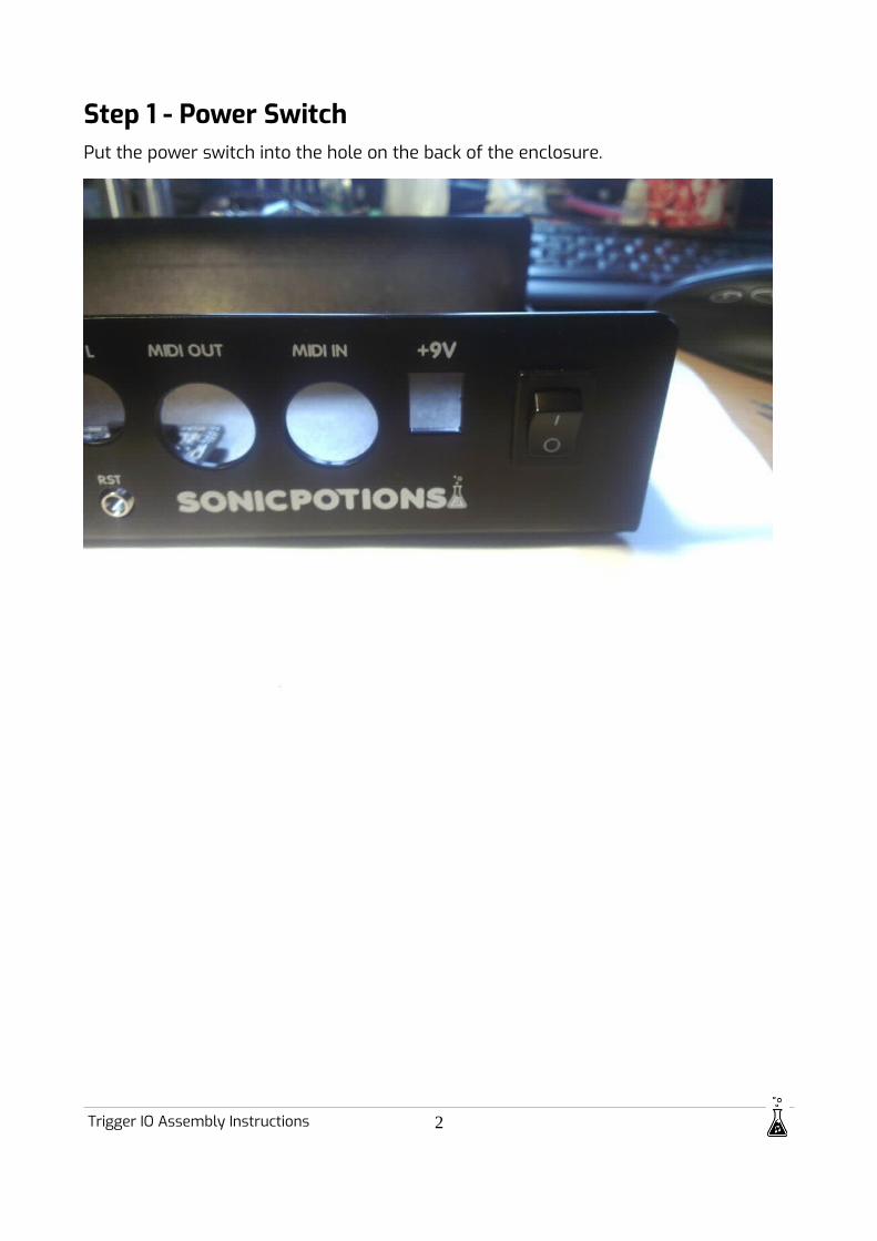
Step 1 - Power SwitchPut the power switch into the hole on the back of the enclosure.
Trigger IO Assembly Instructions 2

Step 2 - Trigger IO PCBUse the 3 white plastic standoffs and the original M3x10cm screws to attach the trigger IO PCB to the bottom part of the enclosure. On newer cases Girts decided to provide additional M3 nuts to the kit. If you don‘t find plastic standoffs in your kit, use 2nuts as standoff. Nut, nut, PCB, nut.
Trigger IO Assembly Instructions 3

Step 3 - Install LXR into topAttach the LXR front PCB to the top part of the enclosure. Use the original screws. There are 5 additional screws supplied with the enclosure to replace the standoffs in the corner that are only used with the acrylic enclosure.
Step 4 - Install LightpipesStarting 2020 we don‘t provide lightpipes with the cases per default anymore. Due to high costs and trouble installing them. LEDs will be mounted flush with the case. If you don‘t have any lightpipes, please skip this step.
Now that the LXR is installed into the top panel, it is time to insert the lightpipes.
This is the most complicated step. The lightpipes are used so that people who already built their LXR don't have to desolder all LEDs to match their height to the new frontpanel. The LEDs can be mounted flush to the PCB and the lightpipes are inserted to the frontpanel.
Cut lightpipes to proper length
The length of the lightpipes is a tight fit. So if the LEDs are installed completely flat onto the PCB, they will fit exactly. But I had a few LEDs that where mounted a little bit too high, so the lightpipe where not flush with the front.
Trigger IO Assembly Instructions 4

Fortunately the lightpipes are quite easy to cut with a side cutter. You just have to be carefull to not cut off too much, or the lightpipe will be too short.So the first step is to insert all the lightpipes into their holes and cut the ones that stand out a little bit shorter
Fix the lightpipes in their holes
Currently there are still some problems with the powder coating process of the enclosure. So either the holes for the lightpipes are to small and the lightpipes won't fit, or as in this production charge the holes are a little bit too big and the lighpipes won't stay in their holes by themselves (depending on the amount of paint). We hope to improve this in the future, but for now the lightpipes have to be fixed into the enclosure by using the provided rubber o-rings. Just slip them onto the lightpipe from below the frontplate.
Trigger IO Assembly Instructions 5
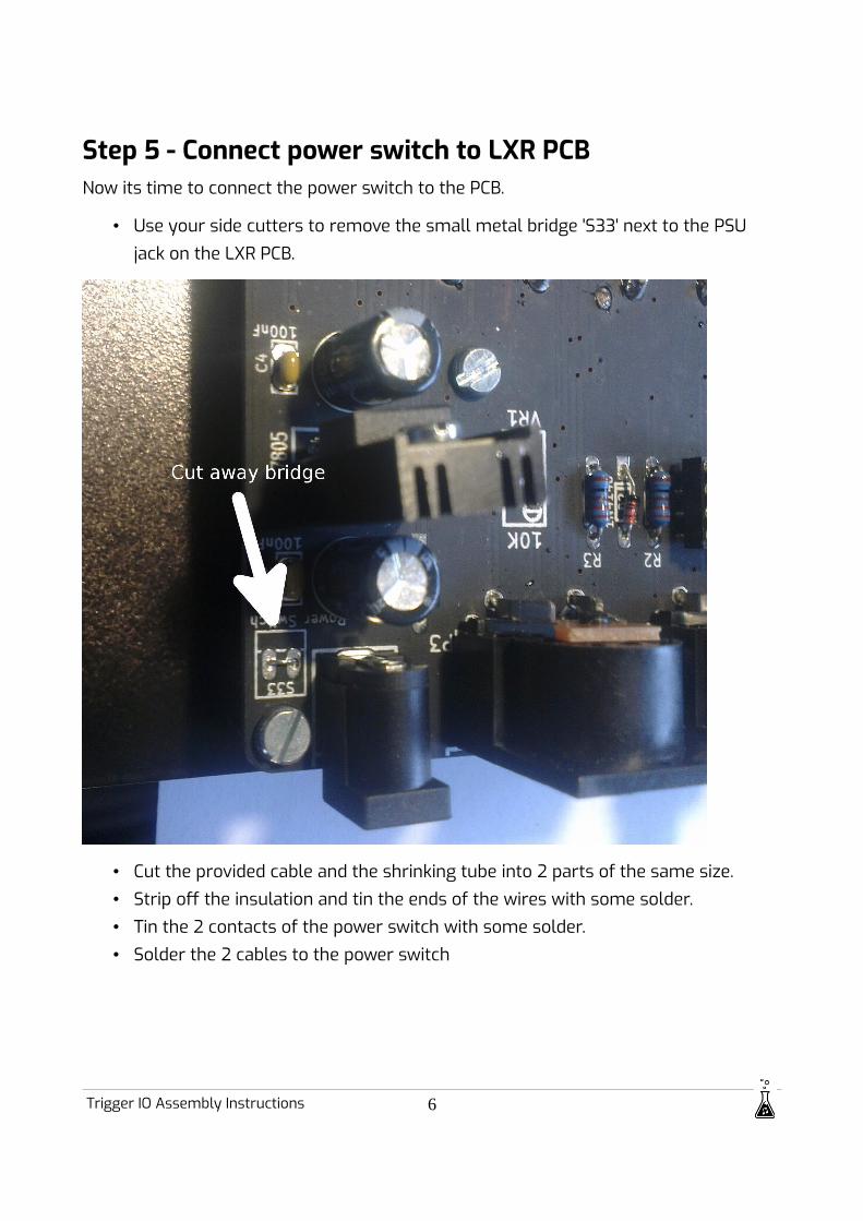
Step 5 - Connect power switch to LXR PCBNow its time to connect the power switch to the PCB.
• Use your side cutters to remove the small metal bridge 'S33' next to the PSU jack on the LXR PCB.
• Cut the provided cable and the shrinking tube into 2 parts of the same size.• Strip off the insulation and tin the ends of the wires with some solder.• Tin the 2 contacts of the power switch with some solder.• Solder the 2 cables to the power switch
Trigger IO Assembly Instructions 6

• Put the shrinking tube on the a power switch contacts
Trigger IO Assembly Instructions 7
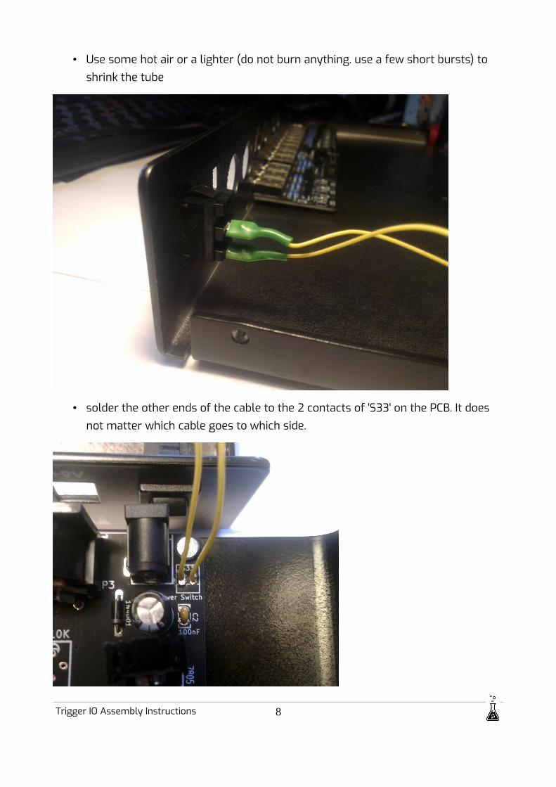
• Use some hot air or a lighter (do not burn anything. use a few short bursts) to shrink the tube
• solder the other ends of the cable to the 2 contacts of 'S33' on the PCB. It does not matter which cable goes to which side.
Trigger IO Assembly Instructions 8

Step 6 - Connect Trigger IONow connect the ribbon cable of the trigger IO.
Step 7 - Assemble enclosure• Put the 2 halves of the enclosure together.• Use the 6 big screws to fasten the top part to the bottom with the holes on the
side.
• Add the 4 plastic nuts to the Audio jacks on the back.
Trigger IO Assembly Instructions 9

Step 8 - Rubber FeetStick the 4 little rubber feet to the bottom of the enclosure.
Step 9 - Add KnobsAdd the knobs to the pots and the encoder and you are done. Enjoy your new rugged metal LXR!
Trigger IO Assembly Instructions 10