Embed Size (px)
Citation preview
1
Before you begin: Turn on the sound on your computer. There is audio to accompany this presentation.
MET 33800 Manufacturing Processes
Chapter 21
Cutting Tools
MET 33800 Manufacturing Processes
Chapter 21
Cutting Tools
Unless otherwise indicated, illustrations in this presentation are taken from the 11th Edition of Degarmo’s Materials and Processes in Manufacturing textbook by J.T. Black and Ronald A. Kohser, ©2012, Wiley.
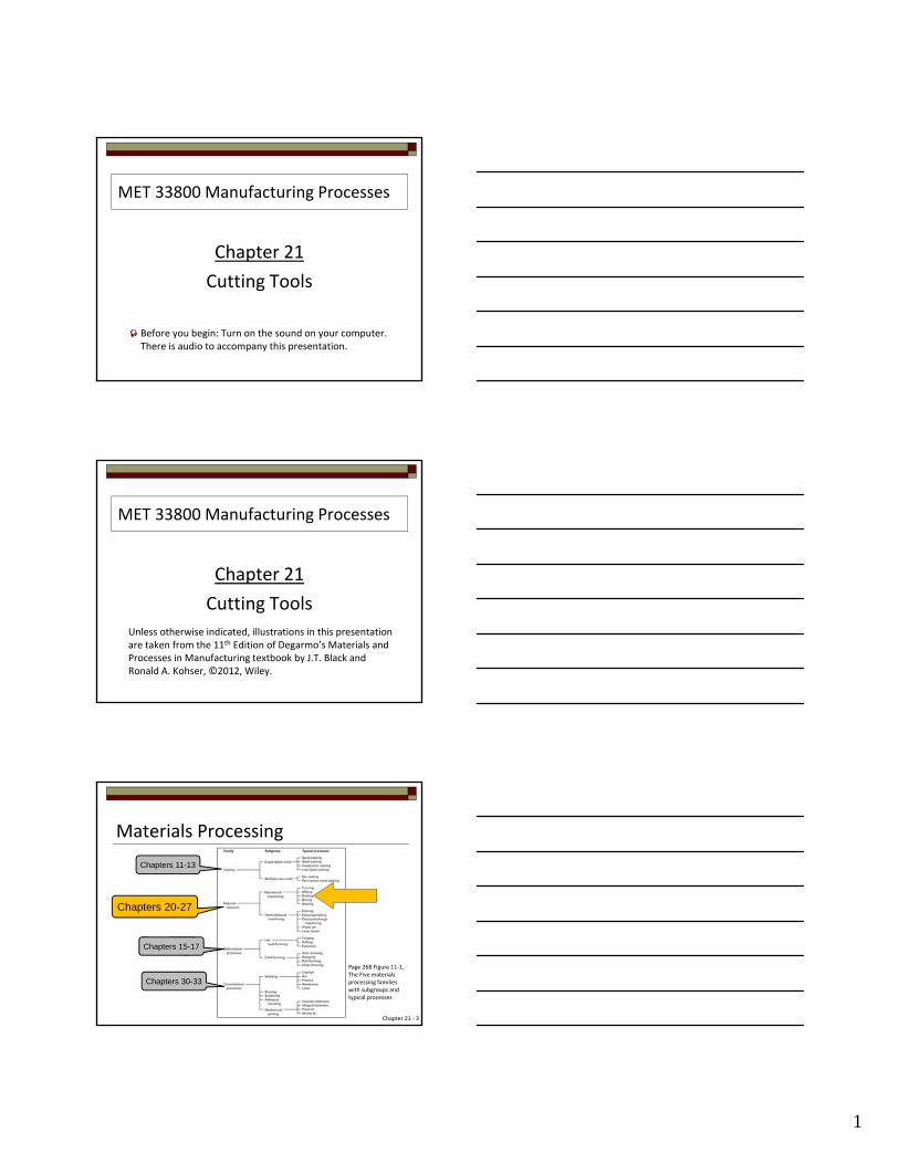
Materials Processing
Chapters 15-17
Chapters 30-33
Chapters 20-27
Chapters 11-13
Chapter 21 ‐ 3
Page 268 Figure 11‐1, The Five materials processing families with subgroups and typical processes
2
“Success in metal cutting depends on selection of the proper cutting tool (material and geometry) for a given work material.”
(Quote from text)
Cutting Tools for Machining
Chapter 21 ‐ 4http://www.yellowpages‐china.com/myimgs/8640340_5128572.jpg
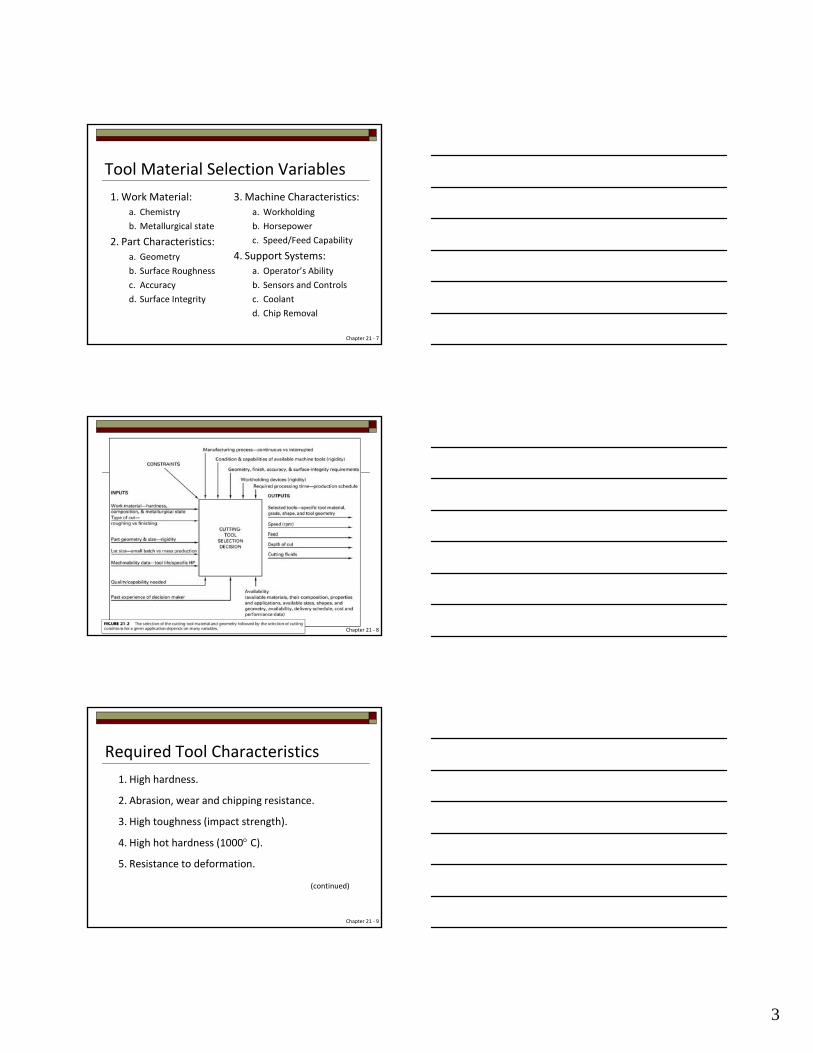
Increase Cutting Speed
Basics
Chapter 21 ‐ 5
Lower Cost Results
MRR Increased
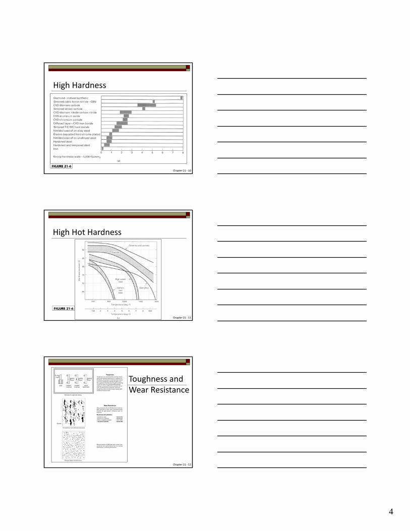
Basics
Chapter 21 ‐ 6
3
Tool Material Selection Variables
1.Work Material:
a. Chemistry
b. Metallurgical state
2. Part Characteristics:
a. Geometry
b. Surface Roughness
c. Accuracy
d. Surface Integrity
3. Machine Characteristics:
a. Workholding
b. Horsepower
c. Speed/Feed Capability
4. Support Systems:
a. Operator’s Ability
b. Sensors and Controls
c. Coolant
d. Chip Removal
Chapter 21 ‐ 7
Chapter 21 ‐ 8
Required Tool Characteristics
1. High hardness.
2. Abrasion, wear and chipping resistance.
3. High toughness (impact strength).
4. High hot hardness (1000 C).
5. Resistance to deformation.
(continued)
Chapter 21 ‐ 9
4
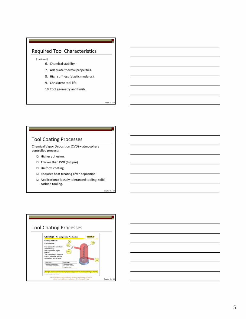
High Hardness
Chapter 21 ‐ 10
High Hot Hardness
Chapter 21 ‐ 11
Toughness and Wear Resistance
Chapter 21 ‐ 12
5
(continued)
6. Chemical stability.
7. Adequate thermal properties.
8. High stiffness (elastic modulus).
9. Consistent tool life.
10.Tool geometry and finish.
Required Tool Characteristics
Chapter 21 ‐ 13
Tool Coating ProcessesChemical Vapor Deposition (CVD) – atmosphere controlled process:
Higher adhesion.
Thicker than PVD (6‐9 μm).
Uniform coating.
Requires heat treating after deposition.
Applications: loosely toleranced tooling; solid carbide tooling.
Chapter 21 ‐ 14
Tool Coating Processes
Chapter 21 ‐ 15http://d2n4wb9orp1vta.cloudfront.net/resources/images/cdn/cms/Co
atings‐‐‐An‐insight‐into‐production‐‐‐GB‐‐‐Handou‐5t‐5.jpg
6
Physical Vapor Deposition (PVD) – physical method:
Line of sight process – reactive sputtering; reactive ion plating; arc evaporation.
Thinner than CVD (1‐3 μm).
Preserves substrate metallurgy; surface finish; edge condition; geometry.
Applications: HSS; solid carbide; carbide‐tipped.
Tool Coating Processes
Chapter 21 ‐ 16
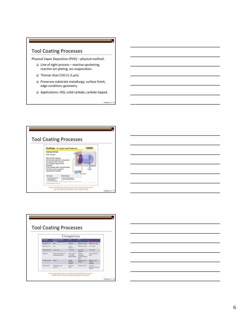
Tool Coating Processes
Chapter 21 ‐ 17
http://d2n4wb9orp1vta.cloudfront.net/resources/images/cdn/cms/Coatings‐‐‐An‐insight‐into‐production‐‐‐GB‐‐‐Handou‐5t‐6.jpg
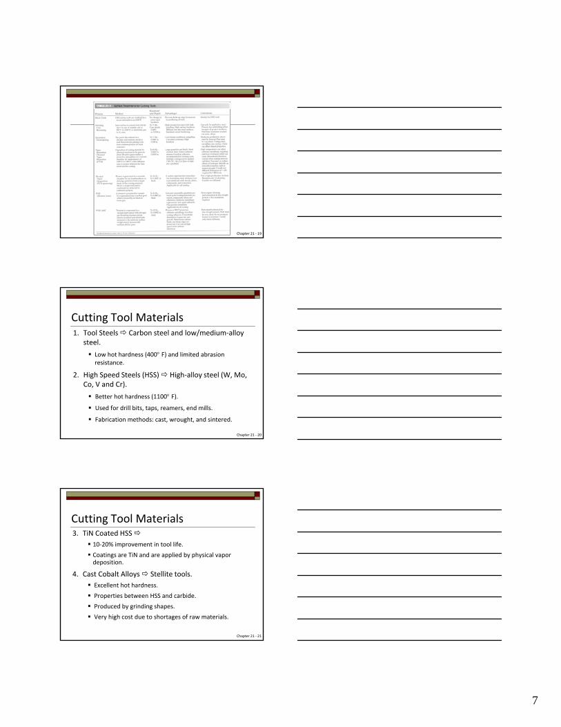
Tool Coating Processes
Chapter 21 ‐ 18
http://image.slidesharecdn.com/spraycoating‐141016162013‐conversion‐gate02/95/thermal‐spray‐coating‐21‐638.jpg?cb=1431711825
7
Chapter 21 ‐ 19
Cutting Tool Materials1. Tool Steels Carbon steel and low/medium‐alloy
steel.
Low hot hardness (400 F) and limited abrasion resistance.
2. High Speed Steels (HSS) High‐alloy steel (W, Mo, Co, V and Cr).
Better hot hardness (1100 F).
Used for drill bits, taps, reamers, end mills.
Fabrication methods: cast, wrought, and sintered.
Chapter 21 ‐ 20
3. TiN Coated HSS 10‐20% improvement in tool life.
Coatings are TiN and are applied by physical vapor deposition.
4. Cast Cobalt Alloys Stellite tools.
Excellent hot hardness.
Properties between HSS and carbide.
Produced by grinding shapes.
Very high cost due to shortages of raw materials.
Cutting Tool Materials
Chapter 21 ‐ 21
8
5. Carbides Various alloys of tungsten carbide. Made by powdered metallurgy.
Binders ‐ cobalt, nickel, molybdenum.
Cemented or insert styles.
6. Coated Carbides
200‐300% improvement in tool life.
Coatings hard, abrasion resistant, chemically inert.
Coatings include: TiC, TiN, Al2O3 and are applied by chemical vapor deposition.
Cutting Tool Materials
Chapter 21 ‐ 22
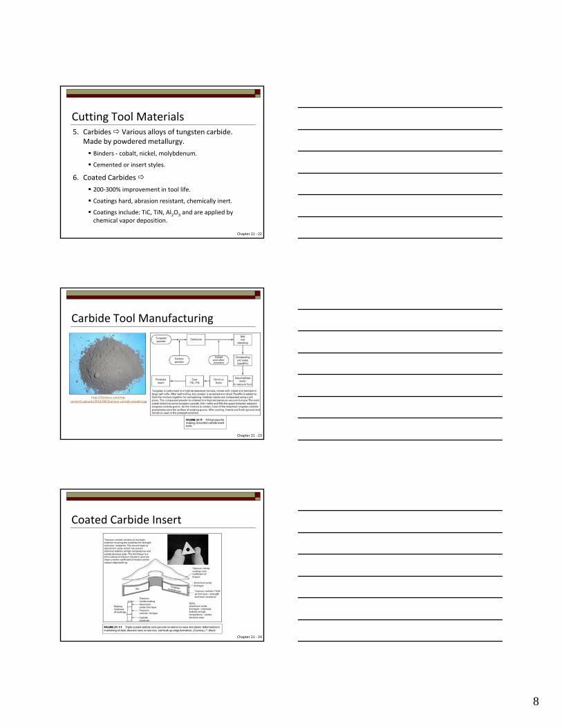
Carbide Tool Manufacturing
Chapter 21 ‐ 23
http://listsbuzz.com/wp‐content/uploads/2014/08/titanium‐carbide‐powder.jpg
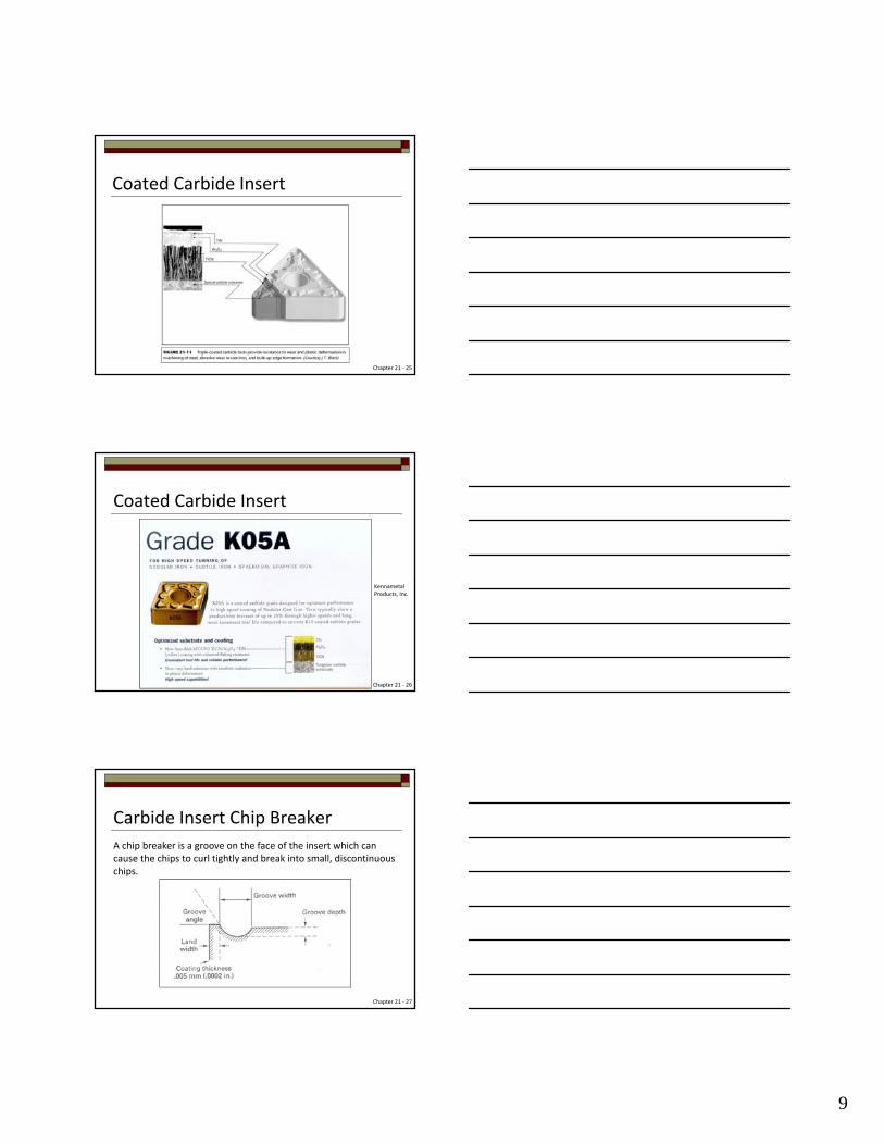
Coated Carbide Insert
Chapter 21 ‐ 24
9
Coated Carbide Insert
Chapter 21 ‐ 25
Coated Carbide Insert
Chapter 21 ‐ 26
Kennametal Products, Inc.
Chapter 21 ‐ 27
Carbide Insert Chip Breaker
A chip breaker is a groove on the face of the insert which can cause the chips to curl tightly and break into small, discontinuous chips.
10
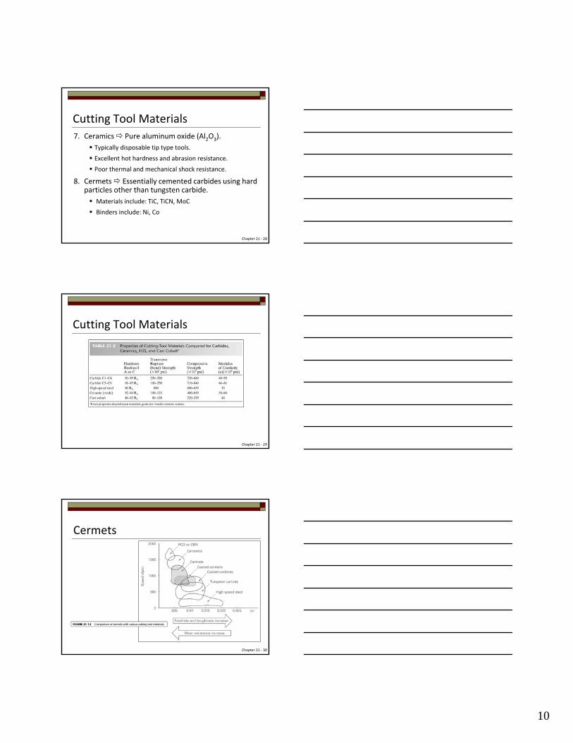
7. Ceramics Pure aluminum oxide (Al2O3).
Typically disposable tip type tools.
Excellent hot hardness and abrasion resistance.
Poor thermal and mechanical shock resistance.
8. Cermets Essentially cemented carbides using hard particles other than tungsten carbide.
Materials include: TiC, TiCN, MoC
Binders include: Ni, Co
Cutting Tool Materials
Chapter 21 ‐ 28
Cutting Tool Materials
Chapter 21 ‐ 29
Cermets
Chapter 21 ‐ 30
11
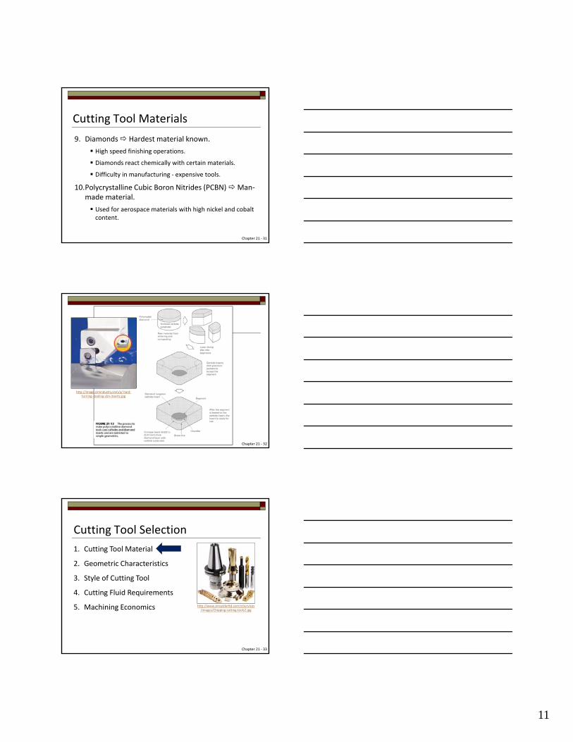
9. Diamonds Hardest material known.
High speed finishing operations.
Diamonds react chemically with certain materials.
Difficulty in manufacturing ‐ expensive tools.
10.Polycrystalline Cubic Boron Nitrides (PCBN) Man‐made material.
Used for aerospace materials with high nickel and cobalt content.
Cutting Tool Materials
Chapter 21 ‐ 31
Chapter 21 ‐ 32
http://image.cimindustry.com/a/‐hard‐turning‐‐tooling‐cbn‐inserts.jpg
Cutting Tool Selection
1. Cutting Tool Material
2. Geometric Characteristics
3. Style of Cutting Tool
4. Cutting Fluid Requirements
5. Machining Economics
Chapter 21 ‐ 33
http://www.simseklerltd.com.tr/services/images/Chipping‐cutting‐tools2.jpg
12
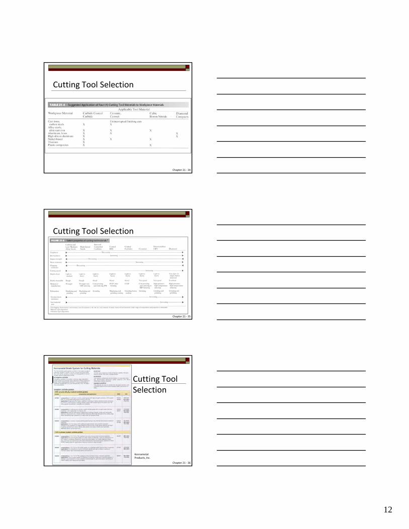
Cutting Tool Selection
Chapter 21 ‐ 34
Cutting Tool Selection
Chapter 21 ‐ 35
Cutting Tool Selection
Chapter 21 ‐ 36
Kennametal Products, Inc.

13
Chapter 21 ‐ 37
Cutting Tool Selection
Kennametal Products, Inc.
Chapter 21 ‐ 38
Cutting Tool Selection
Kennametal Products, Inc.
Cutting Tool Selection
Chapter 21 ‐ 39
Kennametal Products, Inc.
14
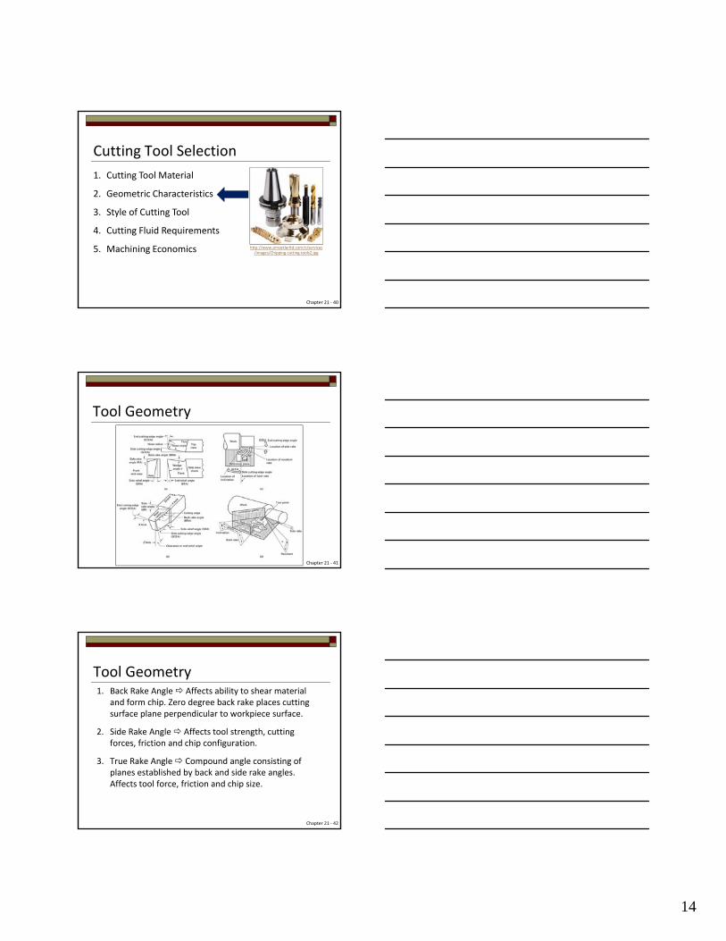
Cutting Tool Selection
1. Cutting Tool Material
2. Geometric Characteristics
3. Style of Cutting Tool
4. Cutting Fluid Requirements
5. Machining Economics
Chapter 21 ‐ 40
http://www.simseklerltd.com.tr/services/images/Chipping‐cutting‐tools2.jpg
Tool Geometry
Chapter 21 ‐ 41
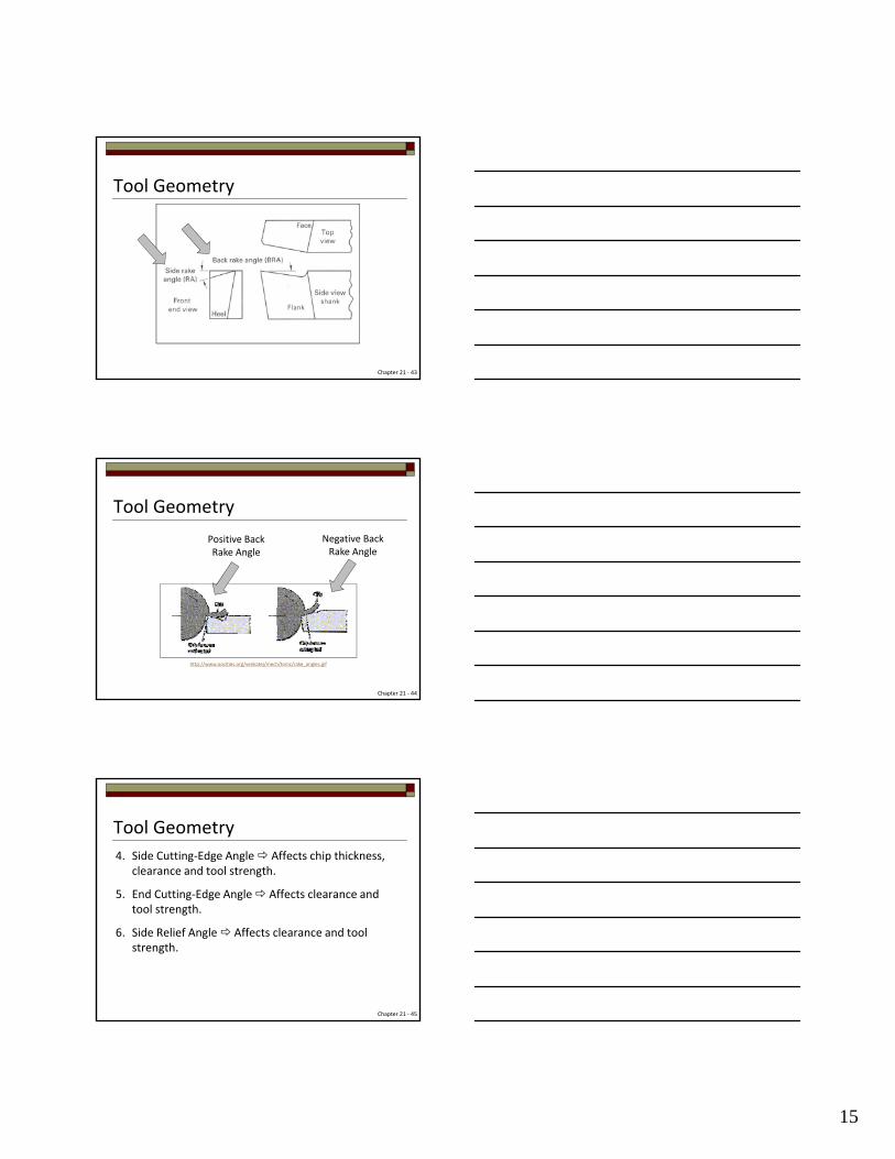
Tool Geometry1. Back Rake Angle Affects ability to shear material
and form chip. Zero degree back rake places cutting surface plane perpendicular to workpiece surface.
2. Side Rake Angle Affects tool strength, cutting forces, friction and chip configuration.
3. True Rake Angle Compound angle consisting of planes established by back and side rake angles. Affects tool force, friction and chip size.
Chapter 21 ‐ 42
15
Tool Geometry
Chapter 21 ‐ 43
Tool Geometry
Chapter 21 ‐ 44
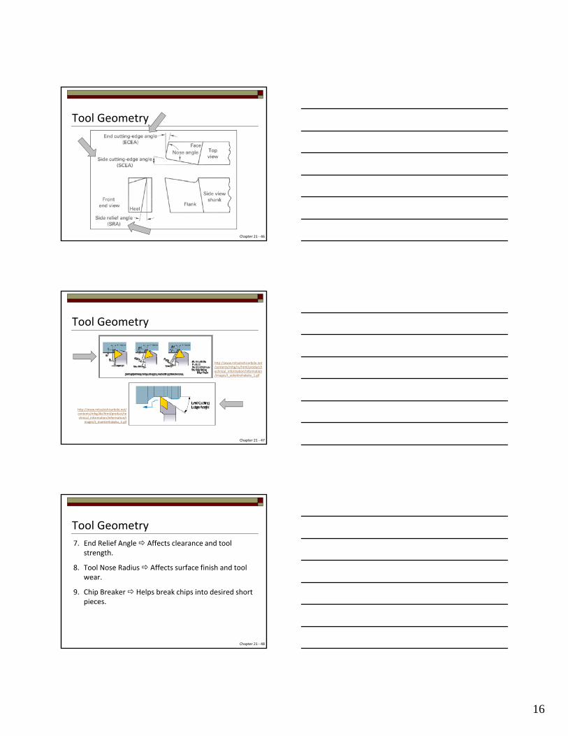
Positive Back Rake Angle
Negative Back Rake Angle
http://www.oocities.org/venkatej/mech/tomc/rake_angles.gif
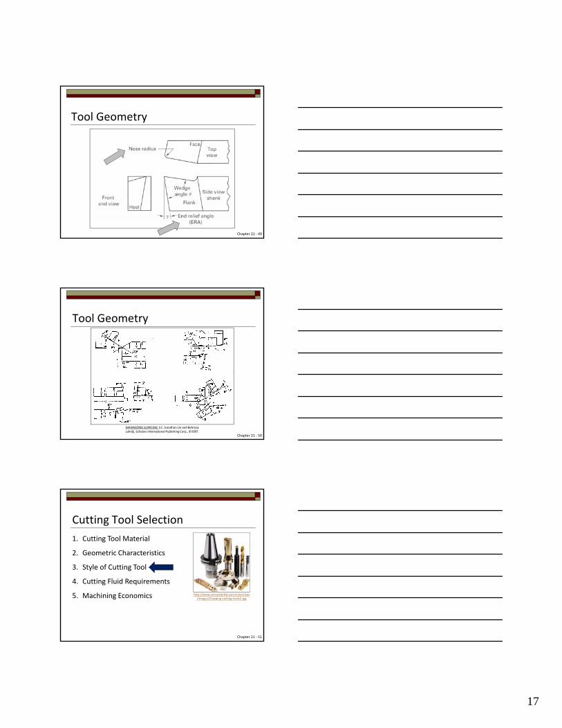
4. Side Cutting‐Edge Angle Affects chip thickness, clearance and tool strength.
5. End Cutting‐Edge Angle Affects clearance and tool strength.
6. Side Relief Angle Affects clearance and tool strength.
Tool Geometry
Chapter 21 ‐ 45
16
Tool Geometry
Chapter 21 ‐ 46
Tool Geometry
Chapter 21 ‐ 47
http://www.mitsubishicarbide.net/contents/mhg/ru/html/product/technical_information/information/images/t_yokokirehakaku_1.gif
http://www.mitsubishicarbide.net/contents/mhg/de/html/product/technical_information/information/i
mages/t_maekirehakaku_1.gif
7. End Relief Angle Affects clearance and tool strength.
8. Tool Nose Radius Affects surface finish and tool wear.
9. Chip Breaker Helps break chips into desired short pieces.
Tool Geometry
Chapter 21 ‐ 48
17
Tool Geometry
Chapter 21 ‐ 49
Tool Geometry
Chapter 21 ‐ 50
MAXIMIZING SURFCAM, S.C. Jonathon Lin and Behrooz Lahidji, Scholars International Publishing Corp., ©1997.
Cutting Tool Selection
1. Cutting Tool Material
2. Geometric Characteristics
3. Style of Cutting Tool
4. Cutting Fluid Requirements
5. Machining Economics
Chapter 21 ‐ 51
http://www.simseklerltd.com.tr/services/images/Chipping‐cutting‐tools2.jpg
18
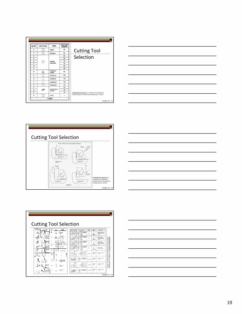
Cutting Tool Selection
Chapter 21 ‐ 52
MAXIMIZING SURFCAM, S.C. Jonathon Lin and Behrooz Lahidji, Scholars International Publishing Corp., ©1997.
Cutting Tool Selection
Chapter 21 ‐ 53
MAXIMIZING SURFCAM, S.C. Jonathon Lin and Behrooz Lahidji, Scholars International Publishing Corp., ©1997.
Cutting Tool Selection
Chapter 21 ‐ 54
MAXIM
IZING SU
RFCA
M, S.C
. Jonath
on Lin
and Behrooz
Lahidji, Sch
olars Intern
ational P
ublish
ing C
orp., ©
1997.
19
Cutting Tool Selection
1. Cutting Tool Material
2. Geometric Characteristics
3. Style of Cutting Tool
4. Cutting Fluid Requirements
5. Machining Economics
Chapter 21 ‐ 55
http://www.simseklerltd.com.tr/services/images/Chipping‐cutting‐tools2.jpg
Cutting FluidsPurpose:
1. Coolant Reduces temperature, which extends tool life and reduces thermal distortion. Primary purpose of a cutting fluid.
2. Lubricant Reduces friction at chip/tool interface and any area tool rubs workpiece.
3. Chip Removal Flushes hot chips away from point of machining.
Chapter 21 ‐ 56
Characteristics:
1. Thermal capacity and conductivity
2. Lubricity
3. Stable and non‐corrosive
4. Nontoxic
Cutting Fluids
Chapter 21 ‐ 57
http://www.newmantools.com/monroe/coolant2.jpg
20
Types:
1. Water
2. Oil
3. Emulsions of water and oil
4. Chemically active compounds
5. Wax
6. Cryogenic – liquid nitrogen
Cutting Fluids
Chapter 21 ‐ 58
http://www.nederman.com/~/media/Problems/Production%20recycling/Coolant/Coolants_and_cutting_fluid.ashx?mw=460
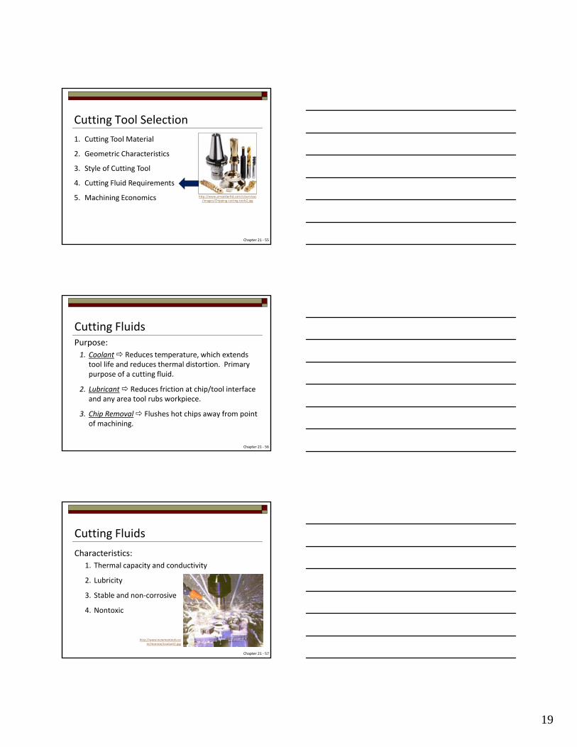
Cutting Fluids
Chapter 21 ‐ 59
Modern Application News, August 2007
Modern Application
News, August 2007
http://americanmachinist.com/site‐files/americanmachinist.com/files/imagecache/large_img/uploads/2012/11/am1108magairproductscryomachining.gif
Cutting Tool Selection
1. Cutting Tool Material
2. Geometric Characteristics
3. Style of Cutting Tool
4. Cutting Fluid Requirements
5. Machining Economics
Chapter 21 ‐ 60
http://www.simseklerltd.com.tr/services/images/Chipping‐cutting‐tools2.jpg
21
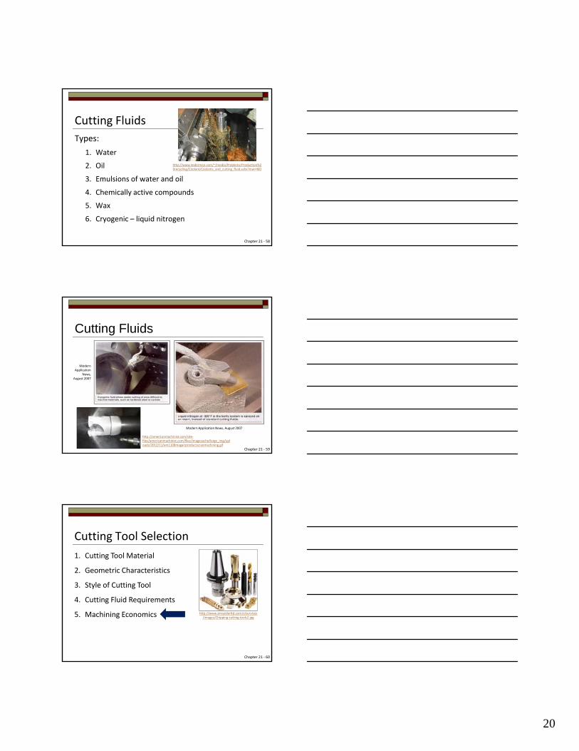
Tool Failure MechanismsSlow‐death mechanism
Gradual tool wear on edge, flank or top, and Built‐up‐Edge (BUE). Changes geometry, which affects power required, surface finish, accuracy and dynamic stability. Predictable.
Sudden‐death mechanism
Deformation, chipping, fracture and/or thermal cracking. Less predicable.
Chapter 21 ‐ 61
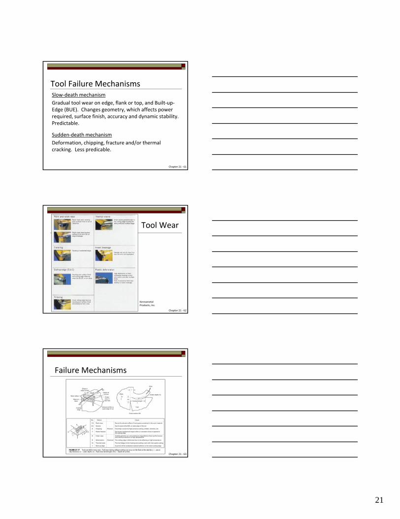
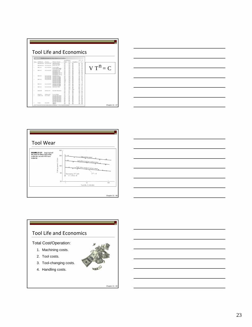
Tool Wear
Chapter 21 ‐ 62
Kennametal Products, Inc.
Failure Mechanisms
Chapter 21 ‐ 63
22
Tool Wear
Chapter 21 ‐ 64
Tool Wear
Chapter 21 ‐ 65
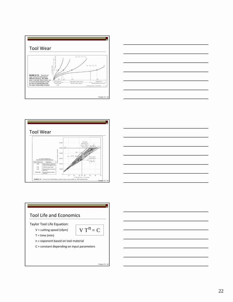
Tool Life and Economics
Taylor Tool Life Equation:
V = cutting speed (sfpm)
T = time (min)
n = exponent based on tool material
C = constant depending on input parameters
nV T = C
Chapter 21 ‐ 66
23
Tool Life and Economics
nV T = C
Chapter 21 ‐ 67
Tool Wear
Chapter 21 ‐ 68
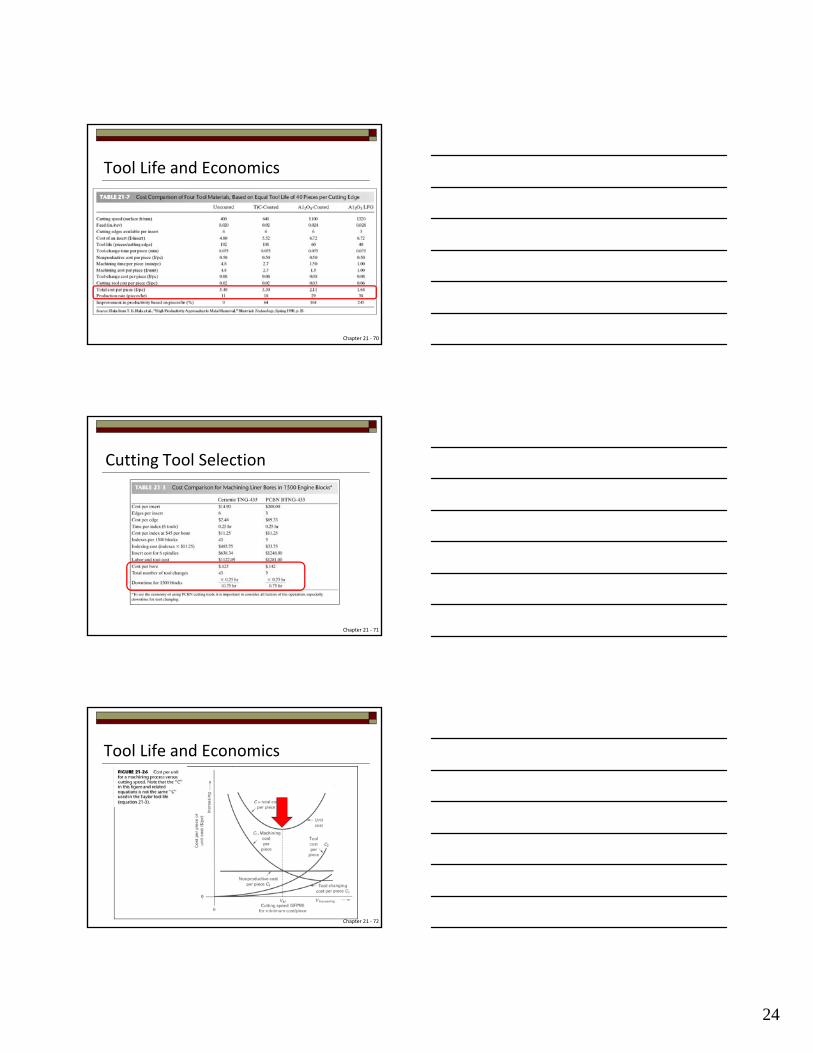
Total Cost/Operation:
1. Machining costs.
2. Tool costs.
3. Tool-changing costs.
4. Handling costs.
Tool Life and Economics
Chapter 21 ‐ 69
24
Tool Life and Economics
Chapter 21 ‐ 70
Cutting Tool Selection
Chapter 21 ‐ 71
Tool Life and Economics
Chapter 21 ‐ 72

25
The End – See Oncourse for Videos
Chapter 21 ‐ 73
http://toolmonger.com/wp-content/uploads/2009/08/studley-tool-chest.jpg