Embed Size (px)
Citation preview
MET Laboratories, Inc. Safety Certification - EMI - Telecom Environmental Simulation
914 WEST PATAPSCO AVENUE ! BALTIMORE, MARYLAND 21230-3432 ! PHONE (410) 354-3300 ! FAX (410) 354-3313
33439 WESTERN AVENUE ● UNION CITY, CALIFORNIA 94587 ● PHONE (510) 489-6300 ● FAX (510) 489-6372
3162 BELICK STREET ● SANTA CLARA, CALIFORNIA 95054 ● PHONE (408 748-3585 ● FAX (510) 489-6372
The Nation’s First Licensed Nationally Recognized Testing Laboratory
April 27, 2011
Ubiquiti Networks
91 E. Tasman
San Jose, CA 95134
Dear Robert Pera,
Enclosed is the EMC Wireless test report for compliance testing of the Ubiquiti Networks, NanoStationLocoM5
as tested to the requirements of Title 47 of the CFR, Ch. 1 (10-1-06 ed.), Part 15, Subpart B, ICES-003, Issue 4
February 2004 for a Class A Digital Device and FCC Part 15 Subpart C, RSS-210, Issue 8, Dec. 2010 for
Intentional Radiators.
Thank you for using the services of MET Laboratories, Inc. If you have any questions regarding these results or
if MET can be of further service to you, please feel free to contact me.
Sincerely yours,
MET LABORATORIES, INC.
Jennifer Warnell
Documentation Department
Reference: (\Ubiquiti Networks\EMCS82946-FCC247)
Certificates and reports shall not be reproduced except in full, without the written permission of MET Laboratories, Inc.
Electromagnetic Compatibility
Ubiquiti Networks Cover Page
NanoStationLocoM5 CFR Title 47, Part 15B, 15.247; RSS-210, Issue 8, Dec. 2010 & ICES-003
MET Report: EMCS82946-FCC247 © 2011, MET Laboratories, Inc. Page ii of xvi
DOC-EMC702 6/18/2009
Electromagnetic Compatibility Criteria
Test Report
for the
Ubiquiti Networks
NanoStationLocoM5
Tested under
the FCC Certification Rules
contained in
Title 47 of the CFR, Parts 15 Subpart B & ICES-003
for Class A Digital Devices
&
15.247 Subpart C & RSS-210, Issue 8, Dec. 2010
for Intentional Radiators
MET Report: EMCS82946-FCC247
April 27, 2011
Prepared For:
Ubiquiti Networks
91 E. Tasman
San Jose, CA 95134
Prepared By:
MET Laboratories, Inc.
3162 Belick St.
Santa Clara, CA 95054
Electromagnetic Compatibility
Ubiquiti Networks Cover Page
NanoStationLocoM5 CFR Title 47, Part 15B, 15.247; RSS-210, Issue 8, Dec. 2010 & ICES-003
MET Report: EMCS82946-FCC247 © 2011, MET Laboratories, Inc. Page iii of xvi
DOC-EMC702 6/18/2009
Electromagnetic Compatibility Criteria
Test Report
for the
Ubiquiti Networks
NanoStationLocoM5
Tested under
the FCC Certification Rules
contained in
Title 47 of the CFR, Parts 15 Subpart B & ICES-003
for Class A Digital Devices
&
15.247 Subpart C & RSS-210, Issue 8, Dec. 2010
for Intentional Radiators
Lionel Gabrillo, Project Engineer Jennifer Warnell
Electromagnetic Compatibility Lab Documentation Department
Engineering Statement: The measurements shown in this report were made in accordance with the procedures indicated, and the
emissions from this equipment were found to be within the limits applicable. I assume full responsibility for the accuracy and
completeness of these measurements, and for the qualifications of all persons taking them. It is further stated that upon the basis of the
measurements made, the equipment tested is capable of operation in accordance with the requirements of the FCC Rules Parts 15B,
15.247 and Industry Canada standards ICES-003, Issue 4 February 2004, RSS-210, Issue 8, Dec. 2010 under normal use and
maintenance.
Shawn McMillen,
Wireless Manager, Electromagnetic Compatibility Lab
Electromagnetic Compatibility
Ubiquiti Networks Report Status
NanoStationLocoM5 CFR Title 47, Part 15B, 15.247; RSS-210, Issue 8, Dec. 2010 & ICES-003
MET Report: EMCS82946-FCC247 © 2011, MET Laboratories, Inc. Page iv of xvi
DOC-EMC702 6/18/2009
Report Status Sheet
Revision Report Date Reason for Revision
April 27, 2011 Initial Issue.
Electromagnetic Compatibility
Ubiquiti Networks Table of Contents
NanoStationLocoM5 CFR Title 47, Part 15B, 15.247; RSS-210, Issue 8, Dec. 2010 & ICES-003
MET Report: EMCS82946-FCC247 © 2011, MET Laboratories, Inc. Page v of xvi
DOC-EMC702 6/18/2009
Table of Contents
I. Executive Summary ................................................................................................................................................. 1 A. Purpose of Test ................................................................................................................................................... 2 B. Executive Summary ............................................................................................................................................ 2
II. Equipment Configuration ....................................................................................................................................... 3 A. Overview ............................................................................................................................................................. 4 B. References ........................................................................................................................................................... 5 C. Test Site .............................................................................................................................................................. 5 D. Description of Test Sample ................................................................................................................................. 6 E. Equipment Configuration .................................................................................................................................... 8 F. Support Equipment ............................................................................................................................................. 8 G. Ports and Cabling Information ............................................................................................................................ 8 H. Mode of Operation .............................................................................................................................................. 9 I. Method of Monitoring EUT Operation ............................................................................................................... 9 J. Modifications ...................................................................................................................................................... 9
a) Modifications to EUT .................................................................................................................... 9 b) Modifications to Test Standard ...................................................................................................... 9
K. Disposition of EUT ............................................................................................................................................. 9 III. Electromagnetic Compatibility Criteria for Unintentional Radiators .............................................................. 10
§ 15.107(a) Conducted Emissions Limits .............................................................................................................. 11 § 15.109(a) Radiated Emissions Limits ................................................................................................................. 17
IV. Electromagnetic Compatibility Criteria for Intentional Radiators ................................................................... 23 § 15.203 Antenna Requirement ............................................................................................................................. 24 § 15.207(a) Conducted Emissions Limits .............................................................................................................. 25 § 15.247(a)(a) 6 dB and 99% Bandwidth .............................................................................................................. 31 § 15.247(b) Peak Power Output ............................................................................................................................ 64 § 15.247(d) Radiated Spurious Emissions Requirements and Band Edge ............................................................ 82 § 15.247(d) RF Conducted Spurious Emissions Requirements and Band Edge .................................................. 118 § 15.247(e) Peak Power Spectral Density ........................................................................................................... 173 RSS-GEN Receiver Spurious Emissions ............................................................................................................. 193
V. Test Equipment .................................................................................................................................................... 196 VI. Certification & User’s Manual Information ...................................................................................................... 198
A. Certification Information ................................................................................................................................ 199 B. Label and User’s Manual Information ............................................................................................................ 203
VII. ICES-003 Procedural & Labeling Requirements .............................................................................................. 205
Electromagnetic Compatibility
Ubiquiti Networks Table of Contents
NanoStationLocoM5 CFR Title 47, Part 15B, 15.247; RSS-210, Issue 8, Dec. 2010 & ICES-003
MET Report: EMCS82946-FCC247 © 2011, MET Laboratories, Inc. Page vi of xvi
DOC-EMC702 6/18/2009
List of Tables
Table 1. Executive Summary of EMC Part 15.247 ComplianceTesting ................................................................................ 2 Table 2. EUT Summary Table................................................................................................................................................ 4 Table 3. References ................................................................................................................................................................ 5 Table 4. Equipment Configuration ......................................................................................................................................... 8 Table 5. Support Equipment ................................................................................................................................................... 8 Table 6. Ports and Cabling Information ................................................................................................................................. 8 Table 7. Conducted Limits for Radio Frequency Devices calculated from FCC Part 15 Subsections 15.107(a) (b) and
15.207(a) ....................................................................................................................................................................... 11 Table 8. Conducted Emissions - Voltage, AC Power, Phase Line (120 VAC, 60 Hz), Cetus PSU ..................................... 12 Table 9. Conducted Emissions - Voltage, AC Power, Neutral Line (120 VAC, 60 Hz), Cetus PSU ................................... 13 Table 10. Conducted Emissions - Voltage, AC Power, Phase Line (120 VAC, 60 Hz), GME PSU .................................... 14 Table 11. Conducted Emissions - Voltage, AC Power, Neutral Line (120 VAC, 60 Hz), GME PSU ................................. 15 Table 12. Radiated Emissions Limits calculated from FCC Part 15, §15.109 (a) (b) .......................................................... 17 Table 13. Radiated Emissions Limits, Test Results, Cetus PSU, FCC Limits ..................................................................... 18 Table 14. Radiated Emissions Limits, Test Results, Cetus PSU, ICES-003 Limits ............................................................. 19 Table 15. Radiated Emissions Limits, Test Results, GME PSU, FCC Limits ...................................................................... 20 Table 16. Radiated Emissions Limits, Test Results, GME PSU, ICES-003 Limits ............................................................. 21 Table 17. Conducted Limits for Intentional Radiators from FCC Part 15 § 15.207(a) ........................................................ 25 Table 18. Conducted Emissions, 15.207(a), Phase Line, Test Results, Cetus PSU .............................................................. 26 Table 19. Conducted Emissions, 15.207(a), Neutral Line, Test Results, Cetus PSU ........................................................... 27 Table 20. Conducted Emissions, 15.207(a), Phase Line, Test Results, GME PSU .............................................................. 28 Table 21. Conducted Emissions, 15.207(a), Neutral Line, Test Results, GME PSU ........................................................... 29 Table 22. 6 dB Occupied Bandwidth, Test Results, Port 1 .................................................................................................. 32 Table 23. 6 dB Occupied Bandwidth, Test Results, Port 2 .................................................................................................. 33 Table 24. 99% Occupied Bandwidth, Test Results, Port 1 ................................................................................................... 34 Table 25. 99% Occupied Bandwidth, Test Results, Port 2 ................................................................................................... 35 Table 26. Output Power Requirements from §15.247(b) ..................................................................................................... 64 Table 27. Peak Power Output, Test Results, Port 1 .............................................................................................................. 65 Table 28. Peak Power Output, Test Results, Port 2 .............................................................................................................. 66 Table 29. Peak Power Output, Test Results, Summed ......................................................................................................... 67 Table 30. Restricted Bands of Operation .............................................................................................................................. 82 Table 31. Radiated Emissions Limits Calculated from FCC Part 15, § 15.209 (a) .............................................................. 83 Table 32. Radiated Spurious Emissions, 802.11n HT5 ........................................................................................................ 84 Table 33. Radiated Spurious Emissions, 802.11n HT8 ........................................................................................................ 84 Table 34. Radiated Spurious Emissions, 802.11n HT10 ...................................................................................................... 84 Table 35. Radiated Spurious Emissions, 802.11n HT20 ...................................................................................................... 84 Table 36. Radiated Spurious Emissions, 802.11n HT30 ...................................................................................................... 84 Table 37. Radiated Spurious Emissions, 802.11n HT40 ...................................................................................................... 85 Table 38. Peak Power Spectral Density, Test Results, 802.11a 20 MHz ........................................................................... 174 Table 39. Peak Power Spectral Density, Test Results, 802.11a 40 MHz ........................................................................... 174 Table 40. Peak Power Spectral Density, Test Results, Port 1, 802.11n HT5 ..................................................................... 174 Table 41. Peak Power Spectral Density, Test Results, Port 1, 802.11n HT8 ..................................................................... 174 Table 42. Peak Power Spectral Density, Test Results, Port 1, 802.11n HT10 ................................................................... 174 Table 43. Peak Power Spectral Density, Test Results, Port 1, 802.11n HT20 ................................................................... 175 Table 44. Peak Power Spectral Density, Test Results, Port 1, 802.11n HT30 ................................................................... 175 Table 45. Peak Power Spectral Density, Test Results, Port 1, 802.11n HT40 ................................................................... 175 Table 46. Peak Power Spectral Density, Test Results, Port 2, 802.11n HT5 ..................................................................... 175 Table 47. Peak Power Spectral Density, Test Results, Port 2, 802.11n HT8 ..................................................................... 175 Table 48. Peak Power Spectral Density, Test Results, Port 2, 802.11n HT10 ................................................................... 176 Table 49. Peak Power Spectral Density, Test Results, Port 2, 802.11n HT20 ................................................................... 176 Table 50. Peak Power Spectral Density, Test Results, Port 2, 802.11n HT30 ................................................................... 176
Electromagnetic Compatibility
Ubiquiti Networks Table of Contents
NanoStationLocoM5 CFR Title 47, Part 15B, 15.247; RSS-210, Issue 8, Dec. 2010 & ICES-003
MET Report: EMCS82946-FCC247 © 2011, MET Laboratories, Inc. Page vii of xvi
DOC-EMC702 6/18/2009
Table 51. Peak Power Spectral Density, Test Results, Port 2, 802.11n HT40 ................................................................... 176 Table 52. Peak Power Spectral Density, Test Results, Summed Ports, 802.11n HT5 ........................................................ 176 Table 53. Peak Power Spectral Density, Test Results, Summed Ports, 802.11n HT8 ........................................................ 177 Table 54. Peak Power Spectral Density, Test Results, Summed Ports, 802.11n HT10 ...................................................... 177 Table 55. Peak Power Spectral Density, Test Results, Summed Ports, 802.11n HT20 ...................................................... 177 Table 56. Peak Power Spectral Density, Test Results, Summed Ports, 802.11n HT30 ...................................................... 177 Table 57. Peak Power Spectral Density, Test Results, Summed Ports, 802.11n HT40 ...................................................... 177 Table 58. Spurious Emission Limits for Receivers ............................................................................................................ 193 Table 59. Test Equipment List ........................................................................................................................................... 197
List of Plots
Plot 1. Conducted Emission, Phase Line Plot, Cetus PSU ................................................................................................... 12 Plot 2. Conducted Emission, Neutral Line Plot, Cetus PSU ................................................................................................. 13 Plot 3. Conducted Emission, Phase Line Plot, GME PSU ................................................................................................... 14 Plot 4. Conducted Emission, Neutral Line Plot, GME PSU ................................................................................................. 15 Plot 5. Radiated Emissions, 30 MHz - 1 GHz, Cetus PSU, FCC Limits .............................................................................. 18 Plot 6. Radiated Emissions, Cetus PSU, ICES-003 Limits .................................................................................................. 19 Plot 7. Radiated Emissions, 30 MHz - 1 GHz, GME PSU, FCC Limits .............................................................................. 20 Plot 8. Radiated Emissions, GME PSU, ICES-003 Limits ................................................................................................... 21 Plot 9. Conducted Emissions, 15.207(a), Phase Line, Cetus PSU ........................................................................................ 26 Plot 10. Conducted Emissions, 15.207(a), Neutral Line, Cetus PSU ................................................................................... 27 Plot 11. Conducted Emissions, 15.207(a), Phase Line, GME PSU ...................................................................................... 28 Plot 12. Conducted Emissions, 15.207(a), Neutral Line, GME PSU ................................................................................... 29 Plot 13. 6 dB Occupied Bandwidth, 802.11a 20 MHz, Low Channel .................................................................................. 36 Plot 14. 6 dB Occupied Bandwidth, 802.11a 20 MHz, Mid Channel ................................................................................... 36 Plot 15. 6 dB Occupied Bandwidth, 802.11a 20 MHz, High Channel ................................................................................. 36 Plot 16. 6 dB Occupied Bandwidth, 802.11a 40 MHz, Low Channel .................................................................................. 37 Plot 17. 6 dB Occupied Bandwidth, 802.11a 40 MHz, Mid Channel ................................................................................... 37 Plot 18. 6 dB Occupied Bandwidth, 802.11a 40 MHz, High Channel ................................................................................. 37 Plot 19. 6 dB Occupied Bandwidth, Low Channel, 802.11n HT5, Port 1 ............................................................................ 38 Plot 20. 6 dB Occupied Bandwidth, Mid Channel, 802.11n HT5, Port 1 ............................................................................. 38 Plot 21. 6 dB Occupied Bandwidth, High Channel, 802.11n HT5, Port 1 ........................................................................... 38 Plot 22. 6 dB Occupied Bandwidth, Low Channel, 802.11n HT5, Port 2 ............................................................................ 39 Plot 23. 6 dB Occupied Bandwidth, Mid Channel, 802.11n HT5, Port 2 ............................................................................. 39 Plot 24. 6 dB Occupied Bandwidth, High Channel, 802.11n HT5, Port 2 ........................................................................... 39 Plot 25. 6 dB Occupied Bandwidth, Low Channel, 802.11n HT8, Port 1 ............................................................................ 40 Plot 26. 6 dB Occupied Bandwidth, Mid Channel, 802.11n HT8, Port 1 ............................................................................. 40 Plot 27. 6 dB Occupied Bandwidth, High Channel, 802.11n HT8, Port 1 ........................................................................... 40 Plot 28. 6 dB Occupied Bandwidth, Low Channel, 802.11n HT8, Port 2 ............................................................................ 41 Plot 29. 6 dB Occupied Bandwidth, Mid Channel, 802.11n HT8, Port 2 ............................................................................. 41 Plot 30. 6 dB Occupied Bandwidth, High Channel, 802.11n HT8, Port 2 ........................................................................... 41 Plot 31. 6 dB Occupied Bandwidth, Low Channel, 802.11n HT10, Port 1 .......................................................................... 42 Plot 32. 6 dB Occupied Bandwidth, Mid Channel, 802.11n HT10, Port 1 ........................................................................... 42 Plot 33. 6 dB Occupied Bandwidth, High Channel, 802.11n HT10, Port 1 ......................................................................... 42 Plot 34. 6 dB Occupied Bandwidth, Low Channel, 802.11n HT10, Port 2 .......................................................................... 43 Plot 35. 6 dB Occupied Bandwidth, Mid Channel, 802.11n HT10, Port 2 ........................................................................... 43 Plot 36. 6 dB Occupied Bandwidth, High Channel, 802.11n HT10, Port 2 ......................................................................... 43 Plot 37. 6 dB Occupied Bandwidth, Low Channel, 802.11n HT20, Port 1 .......................................................................... 44 Plot 38. 6 dB Occupied Bandwidth, Mid Channel, 802.11n HT20, Port 1 ........................................................................... 44 Plot 39. 6 dB Occupied Bandwidth, High Channel, 802.11n HT20, Port 1 ......................................................................... 44 Plot 40. 6 dB Occupied Bandwidth, Low Channel, 802.11n HT20, Port 2 .......................................................................... 45 Plot 41. 6 dB Occupied Bandwidth, Mid Channel, 802.11n HT20, Port 2 ........................................................................... 45
Electromagnetic Compatibility
Ubiquiti Networks Table of Contents
NanoStationLocoM5 CFR Title 47, Part 15B, 15.247; RSS-210, Issue 8, Dec. 2010 & ICES-003
MET Report: EMCS82946-FCC247 © 2011, MET Laboratories, Inc. Page viii of xvi
DOC-EMC702 6/18/2009
Plot 42. 6 dB Occupied Bandwidth, High Channel, 802.11n HT20, Port 2 ......................................................................... 45 Plot 43. 6 dB Occupied Bandwidth, Low Channel, 802.11n HT30, Port 1 .......................................................................... 46 Plot 44. 6 dB Occupied Bandwidth, Mid Channel, 802.11n HT30, Port 1 ........................................................................... 46 Plot 45. 6 dB Occupied Bandwidth, High Channel, 802.11n HT30, Port 1 ......................................................................... 46 Plot 46. 6 dB Occupied Bandwidth, Low Channel, 802.11n HT30, Port 2 .......................................................................... 47 Plot 47. 6 dB Occupied Bandwidth, Mid Channel, 802.11n HT30, Port 2 ........................................................................... 47 Plot 48. 6 dB Occupied Bandwidth, High Channel, 802.11n HT30, Port 2 ......................................................................... 47 Plot 49. 6 dB Occupied Bandwidth, Low Channel, 802.11n HT40, Port 1 .......................................................................... 48 Plot 50. 6 dB Occupied Bandwidth, Mid Channel, 802.11n HT40, Port 1 ........................................................................... 48 Plot 51. 6 dB Occupied Bandwidth, High Channel, 802.11n HT40, Port 1 ......................................................................... 48 Plot 52. 6 dB Occupied Bandwidth, Low Channel, 802.11n HT40, Port 2 .......................................................................... 49 Plot 53. 6 dB Occupied Bandwidth, Mid Channel, 802.11n HT40, Port 2 ........................................................................... 49 Plot 54. 6 dB Occupied Bandwidth, High Channel, 802.11n HT40, Port 2 ......................................................................... 49 Plot 55. 99% Occupied Bandwidth, 802.11a 20 MHz, Low Channel .................................................................................. 50 Plot 56. 99% Occupied Bandwidth, 802.11a 20 MHz, Mid Channel ................................................................................... 50 Plot 57. 99% Occupied Bandwidth, 802.11a 20 MHz, High Channel .................................................................................. 50 Plot 58. 99% Occupied Bandwidth, 802.11a 40 MHz, Low Channel .................................................................................. 51 Plot 59. 99% Occupied Bandwidth, 802.11a 40 MHz, Mid Channel ................................................................................... 51 Plot 60. 99% Occupied Bandwidth, 802.11a 40 MHz, High Channel .................................................................................. 51 Plot 61. 99% Occupied Bandwidth, Low Channel, 802.11n HT5, Port 1 ............................................................................ 52 Plot 62. 99% Occupied Bandwidth, Mid Channel, 802.11n HT5, Port 1 ............................................................................. 52 Plot 63. 99% Occupied Bandwidth, High Channel, 802.11n HT5, Port 1 ............................................................................ 52 Plot 64. 99% Occupied Bandwidth, Low Channel, 802.11n HT5, Port 2 ............................................................................ 53 Plot 65. 99% Occupied Bandwidth, Mid Channel, 802.11n HT5, Port 2 ............................................................................. 53 Plot 66. 99% Occupied Bandwidth, High Channel, 802.11n HT5, Port 2 ............................................................................ 53 Plot 67. 99% Occupied Bandwidth, Low Channel, 802.11n HT8, Port 1 ............................................................................ 54 Plot 68. 99% Occupied Bandwidth, Mid Channel, 802.11n HT8, Port 1 ............................................................................. 54 Plot 69. 99% Occupied Bandwidth, High Channel, 802.11n HT8, Port 1 ............................................................................ 54 Plot 70. 99% Occupied Bandwidth, Low Channel, 802.11n HT8, Port 2 ............................................................................ 55 Plot 71. 99% Occupied Bandwidth, Mid Channel, 802.11n HT8, Port 2 ............................................................................. 55 Plot 72. 99% Occupied Bandwidth, High Channel, 802.11n HT8, Port 2 ............................................................................ 55 Plot 73. 99% Occupied Bandwidth, Low Channel, 802.11n HT10, Port 1 .......................................................................... 56 Plot 74. 99% Occupied Bandwidth, Mid Channel, 802.11n HT10, Port 1 ........................................................................... 56 Plot 75. 99% Occupied Bandwidth, High Channel, 802.11n HT10, Port 1 .......................................................................... 56 Plot 76. 99% Occupied Bandwidth, Low Channel, 802.11n HT10, Port 2 .......................................................................... 57 Plot 77. 99% Occupied Bandwidth, Mid Channel, 802.11n HT10, Port 2 ........................................................................... 57 Plot 78. 99% Occupied Bandwidth, High Channel, 802.11n HT10, Port 2 .......................................................................... 57 Plot 79. 99% Occupied Bandwidth, Low Channel, 802.11n HT20, Port 1 .......................................................................... 58 Plot 80. 99% Occupied Bandwidth, Mid Channel, 802.11n HT20, Port 1 ........................................................................... 58 Plot 81. 99% Occupied Bandwidth, High Channel, 802.11n HT20, Port 1 .......................................................................... 58 Plot 82. 99% Occupied Bandwidth, Low Channel, 802.11n HT20, Port 2 .......................................................................... 59 Plot 83. 99% Occupied Bandwidth, Mid Channel, 802.11n HT20, Port 2 ........................................................................... 59 Plot 84. 99% Occupied Bandwidth, High Channel, 802.11n HT20, Port 2 .......................................................................... 59 Plot 85. 99% Occupied Bandwidth, Low Channel, 802.11n HT30, Port 1 .......................................................................... 60 Plot 86. 99% Occupied Bandwidth, Mid Channel, 802.11n HT30, Port 1 ........................................................................... 60 Plot 87. 99% Occupied Bandwidth, High Channel, 802.11n HT30, Port 1 .......................................................................... 60 Plot 88. 99% Occupied Bandwidth, Low Channel, 802.11n HT30, Port 2 .......................................................................... 61 Plot 89. 99% Occupied Bandwidth, Mid Channel, 802.11n HT30, Port 2 ........................................................................... 61 Plot 90. 99% Occupied Bandwidth, High Channel, 802.11n HT30, Port 2 .......................................................................... 61 Plot 91. 99% Occupied Bandwidth, Low Channel, 802.11n HT40, Port 1 .......................................................................... 62 Plot 92. 99% Occupied Bandwidth, Mid Channel, 802.11n HT40, Port 1 ........................................................................... 62 Plot 93. 99% Occupied Bandwidth, High Channel, 802.11n HT40, Port 1 .......................................................................... 62 Plot 94. 99% Occupied Bandwidth, Low Channel, 802.11n HT40, Port 2 .......................................................................... 63
Electromagnetic Compatibility
Ubiquiti Networks Table of Contents
NanoStationLocoM5 CFR Title 47, Part 15B, 15.247; RSS-210, Issue 8, Dec. 2010 & ICES-003
MET Report: EMCS82946-FCC247 © 2011, MET Laboratories, Inc. Page ix of xvi
DOC-EMC702 6/18/2009
Plot 95. 99% Occupied Bandwidth, Mid Channel, 802.11n HT40, Port 2 ........................................................................... 63 Plot 96. 99% Occupied Bandwidth, High Channel, 802.11n HT40, Port 2 .......................................................................... 63 Plot 97. Peak Power Output, 802.11a 20 MHz, Low Channel ............................................................................................. 68 Plot 98. Peak Power Output, 802.11a 20 MHz, Mid Channel .............................................................................................. 68 Plot 99. Peak Power Output, 802.11a 20 MHz, High Channel ............................................................................................. 68 Plot 100. Peak Power Output, 802.11a 40 MHz, Low Channel ........................................................................................... 69 Plot 101. Peak Power Output, 802.11a 40 MHz, Mid Channel ............................................................................................ 69 Plot 102. Peak Power Output, 802.11a 40 MHz, High Channel ........................................................................................... 69 Plot 103. Peak Power Output, Low Channel, 802.11n HT5, Port 1 ..................................................................................... 70 Plot 104. Peak Power Output, Mid Channel, 802.11n HT5, Port 1 ...................................................................................... 70 Plot 105. Peak Power Output, High Channel, 802.11n HT5, Port 1 ..................................................................................... 70 Plot 106. Peak Power Output, Low Channel, 802.11n HT5, Port 2 ..................................................................................... 71 Plot 107. Peak Power Output, Mid Channel, 802.11n HT5, Port 2 ...................................................................................... 71 Plot 108. Peak Power Output, High Channel, 802.11n HT5, Port 2 ..................................................................................... 71 Plot 109. Peak Power Output, Low Channel, 802.11n HT8, Port 1 ..................................................................................... 72 Plot 110. Peak Power Output, Mid Channel, 802.11n HT8, Port 1 ...................................................................................... 72 Plot 111. Peak Power Output, High Channel, 802.11n HT8, Port 1 ..................................................................................... 72 Plot 112. Peak Power Output, Low Channel, 802.11n HT8, Port 2 ..................................................................................... 73 Plot 113. Peak Power Output, Mid Channel, 802.11n HT8, Port 2 ...................................................................................... 73 Plot 114. Peak Power Output, High Channel, 802.11n HT8, Port 2 ..................................................................................... 73 Plot 115. Peak Power Output, Low Channel, 802.11n HT10, Port 1 ................................................................................... 74 Plot 116. Peak Power Output, Mid Channel, 802.11n HT10, Port 1 .................................................................................... 74 Plot 117. Peak Power Output, High Channel, 802.11n HT10, Port 1 ................................................................................... 74 Plot 118. Peak Power Output, Low Channel, 802.11n HT10, Port 2 ................................................................................... 75 Plot 119. Peak Power Output, Mid Channel, 802.11n HT10, Port 2 .................................................................................... 75 Plot 120. Peak Power Output, High Channel, 802.11n HT10, Port 2 ................................................................................... 75 Plot 121. Peak Power Output, Low Channel, 802.11n HT20, Port 1 ................................................................................... 76 Plot 122. Peak Power Output, Mid Channel, 802.11n HT20, Port 1 .................................................................................... 76 Plot 123. Peak Power Output, High Channel, 802.11n HT20, Port 1 ................................................................................... 76 Plot 124. Peak Power Output, Low Channel, 802.11n HT20, Port 2 ................................................................................... 77 Plot 125. Peak Power Output, Mid Channel, 802.11n HT20, Port 2 .................................................................................... 77 Plot 126. Peak Power Output, High Channel, 802.11n HT20, Port 2 ................................................................................... 77 Plot 127. Peak Power Output, Low Channel, 802.11n HT30, Port 1 ................................................................................... 78 Plot 128. Peak Power Output, Mid Channel, 802.11n HT30, Port 1 .................................................................................... 78 Plot 129. Peak Power Output, High Channel, 802.11n HT30, Port 1 ................................................................................... 78 Plot 130. Peak Power Output, Low Channel, 802.11n HT30, Port 2 ................................................................................... 79 Plot 131. Peak Power Output, Mid Channel, 802.11n HT30, Port 2 .................................................................................... 79 Plot 132. Peak Power Output, High Channel, 802.11n HT30, Port 2 ................................................................................... 79 Plot 133. Peak Power Output, Low Channel, 802.11n HT40, Port 1 ................................................................................... 80 Plot 134. Peak Power Output, Mid Channel, 802.11n HT40, Port 1 .................................................................................... 80 Plot 135. Peak Power Output, High Channel, 802.11n HT40, Port 1 ................................................................................... 80 Plot 136. Peak Power Output, Low Channel, 802.11n HT40, Port 2 ................................................................................... 81 Plot 137. Peak Power Output, Mid Channel, 802.11n HT40, Port 2 .................................................................................... 81 Plot 138. Peak Power Output, High Channel, 802.11n HT40, Port 2 ................................................................................... 81 Plot 139. Radiated Spurious Emissions, 802.11a 20 MHz, Low Channel, 30 MHz – 1 GHz .............................................. 86 Plot 140. Radiated Spurious Emissions, 802.11a 20 MHz, Low Channel, 1 GHz – 18 GHz ............................................... 86 Plot 141. Radiated Spurious Emissions, 802.11a 20 MHz, Mid Channel, 30 MHz – 1 GHz ............................................... 86 Plot 142. Radiated Spurious Emissions, 802.11a 20 MHz, Mid Channel, 1 GHz – 18 GHz ............................................... 87 Plot 143. Radiated Spurious Emissions, 802.11a 20 MHz, High Channel, 30 MHz – 1 GHz ............................................. 87 Plot 144. Radiated Spurious Emissions, 802.11a 20 MHz, High Channel, 1 GHz – 18 GHz .............................................. 87 Plot 145. Radiated Spurious Emissions, 802.11a 40 MHz, Low Channel, 30 MHz – 1 GHz .............................................. 88 Plot 146. Radiated Spurious Emissions, 802.11a 40 MHz, Low Channel, 1 GHz – 18 GHz ............................................... 88 Plot 147. Radiated Spurious Emissions, 802.11a 40 MHz, Mid Channel, 30 MHz – 1 GHz ............................................... 88
Electromagnetic Compatibility
Ubiquiti Networks Table of Contents
NanoStationLocoM5 CFR Title 47, Part 15B, 15.247; RSS-210, Issue 8, Dec. 2010 & ICES-003
MET Report: EMCS82946-FCC247 © 2011, MET Laboratories, Inc. Page x of xvi
DOC-EMC702 6/18/2009
Plot 148. Radiated Spurious Emissions, 802.11a 40 MHz, Mid Channel, 1 GHz – 18 GHz ............................................... 89 Plot 149. Radiated Spurious Emissions, 802.11a 40 MHz, High Channel, 30 MHz – 1 GHz ............................................. 89 Plot 150. Radiated Spurious Emissions, 802.11a 40 MHz, High Channel, 1 GHz – 18 GHz .............................................. 89 Plot 151. Radiated Spurious Emissions, Low Channel, 30 MHz – 1 GHz, 802.11n HT5 .................................................... 90 Plot 152. Radiated Spurious Emissions, Low Channel, 1 GHz – 18 GHz, 802.11n HT5 .................................................... 90 Plot 153. Radiated Spurious Emissions, Mid Channel, 30 MHz – 1 GHz, 802.11n HT5 .................................................... 90 Plot 154. Radiated Spurious Emissions, Mid Channel, 1 GHz – 18 GHz, 802.11n HT5 ..................................................... 91 Plot 155. Radiated Spurious Emissions, High Channel, 30 MHz – 1 GHz, 802.11n HT5 ................................................... 91 Plot 156. Radiated Spurious Emissions, High Channel, 1 GHz – 18 GHz, 802.11n HT5 .................................................... 91 Plot 157. Radiated Spurious Emissions, Low Channel, 30 MHz – 1 GHz, 802.11n HT8 .................................................... 92 Plot 158. Radiated Spurious Emissions, Low Channel, 1 GHz – 18 GHz, 802.11n HT8 .................................................... 92 Plot 159. Radiated Spurious Emissions, Mid Channel, 30 MHz – 1 GHz, 802.11n HT8 .................................................... 92 Plot 160. Radiated Spurious Emissions, Mid Channel, 1 GHz – 18 GHz, 802.11n HT8 ..................................................... 93 Plot 161. Radiated Spurious Emissions, High Channel, 30 MHz – 1 GHz, 802.11n HT8 ................................................... 93 Plot 162. Radiated Spurious Emissions, High Channel, 1 GHz – 18 GHz, 802.11n HT8 .................................................... 93 Plot 163. Radiated Spurious Emissions, Low Channel, 30 MHz – 1 GHz, 802.11n HT10 .................................................. 94 Plot 164. Radiated Spurious Emissions, Low Channel, 1 GHz – 18 GHz, 802.11n HT10 .................................................. 94 Plot 165. Radiated Spurious Emissions, Mid Channel, 30 MHz – 1 GHz, 802.11n HT10 .................................................. 94 Plot 166. Radiated Spurious Emissions, Mid Channel, 1 GHz – 18 GHz, 802.11n HT10 ................................................... 95 Plot 167. Radiated Spurious Emissions, High Channel, 30 MHz – 1 GHz, 802.11n HT10 ................................................. 95 Plot 168. Radiated Spurious Emissions, High Channel, 1 GHz – 18 GHz, 802.11n HT10 .................................................. 95 Plot 169. Radiated Spurious Emissions, Low Channel, 30 MHz – 1 GHz, 802.11n HT20 .................................................. 96 Plot 170. Radiated Spurious Emissions, Low Channel, 1 GHz – 18 GHz, 802.11n HT20 .................................................. 96 Plot 171. Radiated Spurious Emissions, Mid Channel, 30 MHz – 1 GHz, 802.11n HT20 .................................................. 96 Plot 172. Radiated Spurious Emissions, Mid Channel, 1 GHz – 18 GHz, 802.11n HT20 ................................................... 97 Plot 173. Radiated Spurious Emissions, High Channel, 30 MHz – 1 GHz, 802.11n HT20 ................................................. 97 Plot 174. Radiated Spurious Emissions, High Channel, 1 GHz – 18 GHz, 802.11n HT20 .................................................. 97 Plot 175. Radiated Spurious Emissions, Low Channel, 30 MHz – 1 GHz, 802.11n HT30 .................................................. 98 Plot 176. Radiated Spurious Emissions, Low Channel, 1 GHz – 18 GHz, 802.11n HT30 .................................................. 98 Plot 177. Radiated Spurious Emissions, Mid Channel, 30 MHz – 1 GHz, 802.11n HT30 .................................................. 98 Plot 178. Radiated Spurious Emissions, Mid Channel, 1 GHz – 18 GHz, 802.11n HT30 ................................................... 99 Plot 179. Radiated Spurious Emissions, High Channel, 30 MHz – 1 GHz, 802.11n HT30 ................................................. 99 Plot 180. Radiated Spurious Emissions, High Channel, 1 GHz – 18 GHz, 802.11n HT30 .................................................. 99 Plot 181. Radiated Spurious Emissions, Low Channel, 30 MHz – 1 GHz, 802.11n HT40 ................................................ 100 Plot 182. Radiated Spurious Emissions, Low Channel, 1 GHz – 18 GHz, 802.11n HT40 ................................................ 100 Plot 183. Radiated Spurious Emissions, Mid Channel, 30 MHz – 1 GHz, 802.11n HT40 ................................................ 100 Plot 184. Radiated Spurious Emissions, Mid Channel, 1 GHz – 18 GHz, 802.11n HT40 ................................................. 101 Plot 185. Radiated Spurious Emissions, High Channel, 30 MHz – 1 GHz, 802.11n HT40 ............................................... 101 Plot 186. Radiated Spurious Emissions, High Channel, 1 GHz – 18 GHz, 802.11n HT40 ................................................ 101 Plot 187. Radiated Harmonics, Low Channel, 802.11a 20 MHz, 7 GHz – 18 GHz ........................................................... 102 Plot 188. Radiated Harmonics, Mid Channel, 802.11a 20 MHz, 7 GHz – 18 GHz ........................................................... 102 Plot 189. Radiated Harmonics, High Channel, 802.11a 20 MHz, 7 GHz – 18 GHz .......................................................... 102 Plot 190. Radiated Harmonics, Low Channel, 802.11a 40 MHz, 7 GHz – 18 GHz ........................................................... 103 Plot 191. Radiated Harmonics, Mid Channel, 802.11a 40 MHz, 7 GHz – 18 GHz ........................................................... 103 Plot 192. Radiated Harmonics, High Channel, 802.11a 40 MHz, 7 GHz – 18 GHz .......................................................... 103 Plot 193. Radiated Harmonics, Low Channel, 7 GHz – 18 GHz, Average, 802.11n HT5 ................................................. 104 Plot 194. Radiated Harmonics, Low Channel, 7 GHz – 18 GHz, Peak, 802.11n HT5 ....................................................... 104 Plot 195. Radiated Harmonics, Mid Channel, 7 GHz – 18 GHz, Average, 802.11n HT5 .................................................. 104 Plot 196. Radiated Harmonics, Mid Channel, 7 GHz – 18 GHz, Peak, 802.11n HT5 ....................................................... 105 Plot 197. Radiated Harmonics, High Channel, 7 GHz – 18 GHz, Average, 802.11n HT5 ................................................ 105 Plot 198. Radiated Harmonics, High Channel, 7 GHz – 18 GHz, Peak, 802.11n HT5 ...................................................... 105 Plot 199. Radiated Harmonics, Low Channel, 7 GHz – 18 GHz, Average, 802.11n HT8 ................................................. 106 Plot 200. Radiated Harmonics, Low Channel, 7 GHz – 18 GHz, Peak, 802.11n HT8 ....................................................... 106
Electromagnetic Compatibility
Ubiquiti Networks Table of Contents
NanoStationLocoM5 CFR Title 47, Part 15B, 15.247; RSS-210, Issue 8, Dec. 2010 & ICES-003
MET Report: EMCS82946-FCC247 © 2011, MET Laboratories, Inc. Page xi of xvi
DOC-EMC702 6/18/2009
Plot 201. Radiated Harmonics, Mid Channel, 7 GHz – 18 GHz, Average, 802.11n HT8 .................................................. 106 Plot 202. Radiated Harmonics, Mid Channel, 7 GHz – 18 GHz, Peak, 802.11n HT8 ....................................................... 107 Plot 203. Radiated Harmonics, High Channel, 7 GHz – 18 GHz, Average, 802.11n HT8 ................................................ 107 Plot 204. Radiated Harmonics, High Channel, 7 GHz – 18 GHz, Peak, 802.11n HT8 ...................................................... 107 Plot 205. Radiated Harmonics, Low Channel, 7 GHz – 18 GHz, Average, 802.11n HT10 ............................................... 108 Plot 206. Radiated Harmonics, Low Channel, 7 GHz – 18 GHz, Peak, 802.11n HT10 ..................................................... 108 Plot 207. Radiated Harmonics, Mid Channel, 7 GHz – 18 GHz, Average, 802.11n HT10 ................................................ 108 Plot 208. Radiated Harmonics, Mid Channel, 7 GHz – 18 GHz, Peak, 802.11n HT10 ..................................................... 109 Plot 209. Radiated Harmonics, High Channel, 7 GHz – 18 GHz, Average, 802.11n HT10 .............................................. 109 Plot 210. Radiated Harmonics, High Channel, 7 GHz – 18 GHz, Peak, 802.11n HT10 .................................................... 109 Plot 211. Radiated Harmonics, Low Channel, 7 GHz – 18 GHz, Average, 802.11n HT20 ............................................... 110 Plot 212. Radiated Harmonics, Low Channel, 7 GHz – 18 GHz, Peak, 802.11n HT20 ..................................................... 110 Plot 213. Radiated Harmonics, Mid Channel, 7 GHz – 18 GHz, Average, 802.11n HT20 ................................................ 110 Plot 214. Radiated Harmonics, Mid Channel, 7 GHz – 18 GHz, Peak, 802.11n HT20 ..................................................... 111 Plot 215. Radiated Harmonics, High Channel, 7 GHz – 18 GHz, Average, 802.11n HT20 .............................................. 111 Plot 216. Radiated Harmonics, High Channel, 7 GHz – 18 GHz, Peak, 802.11n HT20 .................................................... 111 Plot 217. Radiated Harmonics, Low Channel, 7 GHz – 18 GHz, Average, 802.11n HT30 ............................................... 112 Plot 218. Radiated Harmonics, Low Channel, 7 GHz – 18 GHz, Peak, 802.11n HT30 ..................................................... 112 Plot 219. Radiated Harmonics, Mid Channel, 7 GHz – 18 GHz, Average, 802.11n HT30 ................................................ 112 Plot 220. Radiated Harmonics, Mid Channel, 7 GHz – 18 GHz, Peak, 802.11n HT30 ..................................................... 113 Plot 221. Radiated Harmonics, High Channel, 7 GHz – 18 GHz, Average, 802.11n HT30 .............................................. 113 Plot 222. Radiated Harmonics, High Channel, 7 GHz – 18 GHz, Peak, 802.11n HT30 .................................................... 113 Plot 223. Radiated Harmonics, Low Channel, 7 GHz – 18 GHz, Average, 802.11n HT40 ............................................... 114 Plot 224. Radiated Harmonics, Low Channel, 7 GHz – 18 GHz, Peak, 802.11n HT40 ..................................................... 114 Plot 225. Radiated Harmonics, Mid Channel, 7 GHz – 18 GHz, Average, 802.11n HT40 ................................................ 114 Plot 226. Radiated Harmonics, Mid Channel, 7 GHz – 18 GHz, Peak, 802.11n HT40 ..................................................... 115 Plot 227. Radiated Harmonics, High Channel, 7 GHz – 18 GHz, Average, 802.11n HT40 .............................................. 115 Plot 228. Radiated Harmonics, High Channel, 7 GHz – 18 GHz, Peak, 802.11n HT40 .................................................... 115 Plot 229. Conducted Spurious Emissions, Low Channel, 802.11a 20 MHz, 30 MHz – 1 GHz ......................................... 119 Plot 230. Conducted Spurious Emissions, Low Channel, 802.11a 20 MHz, 1 GHz – 40 GHz .......................................... 119 Plot 231. Conducted Spurious Emissions, Mid Channel, 802.11a 20 MHz, 30 MHz – 1 GHz .......................................... 119 Plot 232. Conducted Spurious Emissions, Mid Channel, 802.11a 20 MHz, 1 GHz – 40 GHz .......................................... 120 Plot 233. Conducted Spurious Emissions, High Channel, 802.11a 20 MHz, 30 MHz – 1 GHz ........................................ 120 Plot 234. Conducted Spurious Emissions, High Channel, 802.11a 20 MHz, 1 GHz – 40 GHz ......................................... 120 Plot 235. Conducted Spurious Emissions, Low Channel, 802.11a 40 MHz, 30 MHz – 1 GHz ......................................... 121 Plot 236. Conducted Spurious Emissions, Low Channel, 802.11a 40 MHz, 1 GHz – 40 GHz .......................................... 121 Plot 237. Conducted Spurious Emissions, Mid Channel, 802.11a 40 MHz, 30 MHz – 1 GHz .......................................... 121 Plot 238. Conducted Spurious Emissions, Mid Channel, 802.11a 40 MHz, 1 GHz – 40 GHz .......................................... 122 Plot 239. Conducted Spurious Emissions, High Channel, 802.11a 40 MHz, 30 MHz – 1 GHz ........................................ 122 Plot 240. Conducted Spurious Emissions, High Channel, 802.11a 40 MHz, 1 GHz – 40 GHz ......................................... 122 Plot 241. Conducted Spurious Emissions, Low Channel, 30 MHz – 1 GHz, 802.11n HT5, Port 1 ................................... 123 Plot 242. Conducted Spurious Emissions, Low Channel, 1 GHz – 26 GHz, 802.11n HT5, Port 1 .................................... 123 Plot 243. Conducted Spurious Emissions, Low Channel, 26 GHz – 40 GHz, 802.11n HT5, Port 1 .................................. 123 Plot 244. Conducted Spurious Emissions, Mid Channel, 30 MHz – 1 GHz, 802.11n HT5, Port 1 .................................... 124 Plot 245. Conducted Spurious Emissions, Mid Channel, 1 GHz – 26 GHz, 802.11n HT5, Port 1 .................................... 124 Plot 246. Conducted Spurious Emissions, Mid Channel, 26 GHz – 40 GHz, 802.11n HT5, Port 1 .................................. 124 Plot 247. Conducted Spurious Emissions, High Channel, 30 MHz – 1 GHz, 802.11n HT5, Port 1 .................................. 125 Plot 248. Conducted Spurious Emissions, High Channel, 1 GHz – 26 GHz, 802.11n HT5, Port 1 ................................... 125 Plot 249. Conducted Spurious Emissions, High Channel, 26 GHz – 40 GHz, 802.11n HT5, Port 1 ................................. 125 Plot 250. Conducted Spurious Emissions, Low Channel, 30 MHz – 1 GHz, 802.11n HT5, Port 2 ................................... 126 Plot 251. Conducted Spurious Emissions, Low Channel, 1 GHz – 26 GHz, 802.11n HT5, Port 2 .................................... 126 Plot 252. Conducted Spurious Emissions, Low Channel, 26 GHz – 40 GHz, 802.11n HT5, Port 2 .................................. 126 Plot 253. Conducted Spurious Emissions, Mid Channel, 30 MHz – 1 GHz, 802.11n HT5, Port 2 .................................... 127
Electromagnetic Compatibility
Ubiquiti Networks Table of Contents
NanoStationLocoM5 CFR Title 47, Part 15B, 15.247; RSS-210, Issue 8, Dec. 2010 & ICES-003
MET Report: EMCS82946-FCC247 © 2011, MET Laboratories, Inc. Page xii of xvi
DOC-EMC702 6/18/2009
Plot 254. Conducted Spurious Emissions, Mid Channel, 1 GHz – 26 GHz, 802.11n HT5, Port 2 .................................... 127 Plot 255. Conducted Spurious Emissions, Mid Channel, 26 GHz – 40 GHz, 802.11n HT5, Port 2 .................................. 127 Plot 256. Conducted Spurious Emissions, High Channel, 30 MHz – 1 GHz, 802.11n HT5, Port 2 .................................. 128 Plot 257. Conducted Spurious Emissions, High Channel, 1 GHz – 26 GHz, 802.11n HT5, Port 2 ................................... 128 Plot 258. Conducted Spurious Emissions, High Channel, 26 GHz – 40 GHz, 802.11n HT5, Port 2 ................................. 128 Plot 259. Conducted Spurious Emissions, Low Channel, 30 MHz – 1 GHz, 802.11n HT8, Port 1 ................................... 129 Plot 260. Conducted Spurious Emissions, Low Channel, 1 GHz – 26 GHz, 802.11n HT8, Port 1 .................................... 129 Plot 261. Conducted Spurious Emissions, Low Channel, 26 GHz – 40 GHz, 802.11n HT8, Port 1 .................................. 129 Plot 262. Conducted Spurious Emissions, Mid Channel, 30 MHz – 1 GHz, 802.11n HT8, Port 1 .................................... 130 Plot 263. Conducted Spurious Emissions, Mid Channel, 1 GHz – 26 GHz, 802.11n HT8, Port 1 .................................... 130 Plot 264. Conducted Spurious Emissions, Mid Channel, 26 GHz – 40 GHz, 802.11n HT8, Port 1 .................................. 130 Plot 265. Conducted Spurious Emissions, High Channel, 30 MHz – 1 GHz, 802.11n HT8, Port 1 .................................. 131 Plot 266. Conducted Spurious Emissions, High Channel, 1 GHz – 26 GHz, 802.11n HT8, Port 1 ................................... 131 Plot 267. Conducted Spurious Emissions, High Channel, 26 GHz – 40 GHz, 802.11n HT8, Port 1 ................................. 131 Plot 268. Conducted Spurious Emissions, Low Channel, 30 MHz – 1 GHz, 802.11n HT8, Port 2 ................................... 132 Plot 269. Conducted Spurious Emissions, Low Channel, 1 GHz – 26 GHz, 802.11n HT8, Port 2 .................................... 132 Plot 270. Conducted Spurious Emissions, Low Channel, 26 GHz – 40 GHz, 802.11n HT8, Port 2 .................................. 132 Plot 271. Conducted Spurious Emissions, Mid Channel, 30 MHz – 1 GHz, 802.11n HT8, Port 2 .................................... 133 Plot 272. Conducted Spurious Emissions, Mid Channel, 1 GHz – 26 GHz, 802.11n HT8, Port 2 .................................... 133 Plot 273. Conducted Spurious Emissions, Mid Channel, 26 GHz – 40 GHz, 802.11n HT8, Port 2 .................................. 133 Plot 274. Conducted Spurious Emissions, High Channel, 30 MHz – 1 GHz, 802.11n HT8, Port 2 .................................. 134 Plot 275. Conducted Spurious Emissions, High Channel, 1 GHz – 26 GHz, 802.11n HT8, Port 2 ................................... 134 Plot 276. Conducted Spurious Emissions, High Channel, 26 GHz – 40 GHz, 802.11n HT8, Port 2 ................................. 134 Plot 277. Conducted Spurious Emissions, Low Channel, 30 MHz – 1 GHz, 802.11n HT10, Port 1 ................................. 135 Plot 278. Conducted Spurious Emissions, Low Channel, 1 GHz – 26 GHz, 802.11n HT10, Port 1 .................................. 135 Plot 279. Conducted Spurious Emissions, Low Channel, 26 GHz – 40 GHz, 802.11n HT10, Port 1 ................................ 135 Plot 280. Conducted Spurious Emissions, Mid Channel, 30 MHz – 1 GHz, 802.11n HT10, Port 1 .................................. 136 Plot 281. Conducted Spurious Emissions, Mid Channel, 1 GHz – 26 GHz, 802.11n HT10, Port 1 .................................. 136 Plot 282. Conducted Spurious Emissions, Mid Channel, 26 GHz – 40 GHz, 802.11n HT10, Port 1 ................................ 136 Plot 283. Conducted Spurious Emissions, High Channel, 30 MHz – 1 GHz, 802.11n HT10, Port 1 ................................ 137 Plot 284. Conducted Spurious Emissions, High Channel, 1 GHz – 26 GHz, 802.11n HT10, Port 1 ................................. 137 Plot 285. Conducted Spurious Emissions, High Channel, 26 GHz – 40 GHz, 802.11n HT10, Port 1 ............................... 137 Plot 286. Conducted Spurious Emissions, Low Channel, 30 MHz – 1 GHz, 802.11n HT10, Port 2 ................................. 138 Plot 287. Conducted Spurious Emissions, Low Channel, 1 GHz – 26 GHz, 802.11n HT10, Port 2 .................................. 138 Plot 288. Conducted Spurious Emissions, Low Channel, 26 GHz – 40 GHz, 802.11n HT10, Port 2 ................................ 138 Plot 289. Conducted Spurious Emissions, Mid Channel, 30 MHz – 1 GHz, 802.11n HT10, Port 2 .................................. 139 Plot 290. Conducted Spurious Emissions, Mid Channel, 1 GHz – 26 GHz, 802.11n HT10, Port 2 .................................. 139 Plot 291. Conducted Spurious Emissions, Mid Channel, 26 GHz – 40 GHz, 802.11n HT10, Port 2 ................................ 139 Plot 292. Conducted Spurious Emissions, High Channel, 30 MHz – 1 GHz, 802.11n HT10, Port 2 ................................ 140 Plot 293. Conducted Spurious Emissions, High Channel, 1 GHz – 26 GHz, 802.11n HT10, Port 2 ................................. 140 Plot 294. Conducted Spurious Emissions, High Channel, 26 GHz – 40 GHz, 802.11n HT10, Port 2 ............................... 140 Plot 295. Conducted Spurious Emissions, Low Channel, 30 MHz – 1 GHz, 802.11n HT20, Port 1 ................................. 141 Plot 296. Conducted Spurious Emissions, Low Channel, 1 GHz – 26 GHz, 802.11n HT20, Port 1 .................................. 141 Plot 297. Conducted Spurious Emissions, Low Channel, 26 GHz – 40 GHz, 802.11n HT20, Port 1 ................................ 141 Plot 298. Conducted Spurious Emissions, Mid Channel, 30 MHz – 1 GHz, 802.11n HT20, Port 1 .................................. 142 Plot 299. Conducted Spurious Emissions, Mid Channel, 1 GHz – 26 GHz, 802.11n HT20, Port 1 .................................. 142 Plot 300. Conducted Spurious Emissions, Mid Channel, 26 GHz – 40 GHz, 802.11n HT20, Port 1 ................................ 142 Plot 301. Conducted Spurious Emissions, High Channel, 30 MHz – 1 GHz, 802.11n HT20, Port 1 ................................ 143 Plot 302. Conducted Spurious Emissions, High Channel, 1 GHz – 26 GHz, 802.11n HT20, Port 1 ................................. 143 Plot 303. Conducted Spurious Emissions, High Channel, 26 GHz – 40 GHz, 802.11n HT20, Port 1 ............................... 143 Plot 304. Conducted Spurious Emissions, Low Channel, 30 MHz – 1 GHz, 802.11n HT20, Port 2 ................................. 144 Plot 305. Conducted Spurious Emissions, Low Channel, 1 GHz – 26 GHz, 802.11n HT20, Port 2 .................................. 144 Plot 306. Conducted Spurious Emissions, Low Channel, 26 GHz – 40 GHz, 802.11n HT20, Port 2 ................................ 144
Electromagnetic Compatibility
Ubiquiti Networks Table of Contents
NanoStationLocoM5 CFR Title 47, Part 15B, 15.247; RSS-210, Issue 8, Dec. 2010 & ICES-003
MET Report: EMCS82946-FCC247 © 2011, MET Laboratories, Inc. Page xiii of xvi
DOC-EMC702 6/18/2009
Plot 307. Conducted Spurious Emissions, Mid Channel, 30 MHz – 1 GHz, 802.11n HT20, Port 2 .................................. 145 Plot 308. Conducted Spurious Emissions, Mid Channel, 1 GHz – 26 GHz, 802.11n HT20, Port 2 .................................. 145 Plot 309. Conducted Spurious Emissions, Mid Channel, 26 GHz – 40 GHz, 802.11n HT20, Port 2 ................................ 145 Plot 310. Conducted Spurious Emissions, High Channel, 30 MHz – 1 GHz, 802.11n HT20, Port 2 ................................ 146 Plot 311. Conducted Spurious Emissions, High Channel, 1 GHz – 26 GHz, 802.11n HT20, Port 2 ................................. 146 Plot 312. Conducted Spurious Emissions, High Channel, 26 GHz – 40 GHz, 802.11n HT20, Port 2 ............................... 146 Plot 313. Conducted Spurious Emissions, Low Channel, 30 MHz – 1 GHz, 802.11n HT30, Port 1 ................................. 147 Plot 314. Conducted Spurious Emissions, Low Channel, 1 GHz – 26 GHz, 802.11n HT30, Port 1 .................................. 147 Plot 315. Conducted Spurious Emissions, Low Channel, 26 GHz – 40 GHz, 802.11n HT30, Port 1 ................................ 147 Plot 316. Conducted Spurious Emissions, Mid Channel, 30 MHz – 1 GHz, 802.11n HT30, Port 1 .................................. 148 Plot 317. Conducted Spurious Emissions, Mid Channel, 1 GHz – 26 GHz, 802.11n HT30, Port 1 .................................. 148 Plot 318. Conducted Spurious Emissions, Mid Channel, 26 GHz – 40 GHz, 802.11n HT30, Port 1 ................................ 148 Plot 319. Conducted Spurious Emissions, High Channel, 30 MHz – 1 GHz, 802.11n HT30, Port 1 ................................ 149 Plot 320. Conducted Spurious Emissions, High Channel, 1 GHz – 26 GHz, 802.11n HT30, Port 1 ................................. 149 Plot 321. Conducted Spurious Emissions, High Channel, 26 GHz – 40 GHz, 802.11n HT30, Port 1 ............................... 149 Plot 322. Conducted Spurious Emissions, Low Channel, 30 MHz – 1 GHz, 802.11n HT30, Port 2 ................................. 150 Plot 323. Conducted Spurious Emissions, Low Channel, 1 GHz – 26 GHz, 802.11n HT30, Port 2 .................................. 150 Plot 324. Conducted Spurious Emissions, Low Channel, 26 GHz – 40 GHz, 802.11n HT30, Port 2 ................................ 150 Plot 325. Conducted Spurious Emissions, Mid Channel, 30 MHz – 1 GHz, 802.11n HT30, Port 2 .................................. 151 Plot 326. Conducted Spurious Emissions, Mid Channel, 1 GHz – 26 GHz, 802.11n HT30, Port 2 .................................. 151 Plot 327. Conducted Spurious Emissions, Mid Channel, 26 GHz – 40 GHz, 802.11n HT30, Port 2 ................................ 151 Plot 328. Conducted Spurious Emissions, High Channel, 30 MHz – 1 GHz, 802.11n HT30, Port 2 ................................ 152 Plot 329. Conducted Spurious Emissions, High Channel, 1 GHz – 26 GHz, 802.11n HT30, Port 2 ................................. 152 Plot 330. Conducted Spurious Emissions, High Channel, 26 GHz – 40 GHz, 802.11n HT30, Port 2 ............................... 152 Plot 331. Conducted Spurious Emissions, Low Channel, 30 MHz – 1 GHz, 802.11n HT40, Port 1 ................................. 153 Plot 332. Conducted Spurious Emissions, Low Channel, 1 GHz – 26 GHz, 802.11n HT40, Port 1 .................................. 153 Plot 333. Conducted Spurious Emissions, Low Channel, 26 GHz – 40 GHz, 802.11n HT40, Port 1 ................................ 153 Plot 334. Conducted Spurious Emissions, Mid Channel, 30 MHz – 1 GHz, 802.11n HT40, Port 1 .................................. 154 Plot 335. Conducted Spurious Emissions, Mid Channel, 1 GHz – 26 GHz, 802.11n HT40, Port 1 .................................. 154 Plot 336. Conducted Spurious Emissions, Mid Channel, 26 GHz – 40 GHz, 802.11n HT40, Port 1 ................................ 154 Plot 337. Conducted Spurious Emissions, High Channel, 30 MHz – 1 GHz, 802.11n HT40, Port 1 ................................ 155 Plot 338. Conducted Spurious Emissions, High Channel, 1 GHz – 26 GHz, 802.11n HT40, Port 1 ................................. 155 Plot 339. Conducted Spurious Emissions, High Channel, 26 GHz – 40 GHz, 802.11n HT40, Port 1 ............................... 155 Plot 340. Conducted Spurious Emissions, Low Channel, 30 MHz – 1 GHz, 802.11n HT40, Port 2 ................................. 156 Plot 341. Conducted Spurious Emissions, Low Channel, 1 GHz – 26 GHz, 802.11n HT40, Port 2 .................................. 156 Plot 342. Conducted Spurious Emissions, Low Channel, 26 GHz – 40 GHz, 802.11n HT40, Port 2 ................................ 156 Plot 343. Conducted Spurious Emissions, Mid Channel, 30 MHz – 1 GHz, 802.11n HT40, Port 2 .................................. 157 Plot 344. Conducted Spurious Emissions, Mid Channel, 1 GHz – 26 GHz, 802.11n HT40, Port 2 .................................. 157 Plot 345. Conducted Spurious Emissions, Mid Channel, 26 GHz – 40 GHz, 802.11n HT40, Port 2 ................................ 157 Plot 346. Conducted Spurious Emissions, High Channel, 30 MHz – 1 GHz, 802.11n HT40, Port 2 ................................ 158 Plot 347. Conducted Spurious Emissions, High Channel, 1 GHz – 26 GHz, 802.11n HT40, Port 2 ................................. 158 Plot 348. Conducted Spurious Emissions, High Channel, 26 GHz – 40 GHz, 802.11n HT40, Port 2 ............................... 158 Plot 349. Conducted Band Edge, Low Channel, 802.11a 20 MHz .................................................................................... 159 Plot 350. Conducted Band Edge, High Channel, 802.11a 20 MHz .................................................................................... 159 Plot 351. Conducted Band Edge, Low Channel, 802.11a 40 MHz .................................................................................... 160 Plot 352. Conducted Band Edge, High Channel, 802.11a 40 MHz .................................................................................... 160 Plot 353. Conducted Band Edge, Low Channel, 802.11n HT5, Port 1 .............................................................................. 161 Plot 354. Conducted Band Edge, High Channel, 802.11n HT5, Port 1 .............................................................................. 161 Plot 355. Conducted Band Edge, Low Channel, 802.11n HT5, Port 2 .............................................................................. 162 Plot 356. Conducted Band Edge, High Channel, 802.11n HT5, Port 2 .............................................................................. 162 Plot 357. Conducted Band Edge, Low Channel, 802.11n HT8, Port 1 .............................................................................. 163 Plot 358. Conducted Band Edge, High Channel, 802.11n HT8, Port 1 .............................................................................. 163 Plot 359. Conducted Band Edge, Low Channel, 802.11n HT8, Port 2 .............................................................................. 164
Electromagnetic Compatibility
Ubiquiti Networks Table of Contents
NanoStationLocoM5 CFR Title 47, Part 15B, 15.247; RSS-210, Issue 8, Dec. 2010 & ICES-003
MET Report: EMCS82946-FCC247 © 2011, MET Laboratories, Inc. Page xiv of xvi
DOC-EMC702 6/18/2009
Plot 360. Conducted Band Edge, High Channel, 802.11n HT8, Port 2 .............................................................................. 164 Plot 361. Conducted Band Edge, Low Channel, 802.11n HT10, Port 1 ............................................................................ 165 Plot 362. Conducted Band Edge, High Channel, 802.11n HT10, Port 1 ............................................................................ 165 Plot 363. Conducted Band Edge, Low Channel, 802.11n HT10, Port 2 ............................................................................ 166 Plot 364. Conducted Band Edge, High Channel, 802.11n HT10, Port 2 ............................................................................ 166 Plot 365. Conducted Band Edge, Low Channel, 802.11n HT20, Port 1 ............................................................................ 167 Plot 366. Conducted Band Edge, High Channel, 802.11n HT20, Port 1 ............................................................................ 167 Plot 367. Conducted Band Edge, Low Channel, 802.11n HT20, Port 2 ............................................................................ 168 Plot 368. Conducted Band Edge, High Channel, 802.11n HT20, Port 2 ............................................................................ 168 Plot 369. Conducted Band Edge, Low Channel, 802.11n HT30, Port 1 ............................................................................ 169 Plot 370. Conducted Band Edge, High Channel, 802.11n HT30, Port 1 ............................................................................ 169 Plot 371. Conducted Band Edge, Low Channel, 802.11n HT30, Port 2 ............................................................................ 170 Plot 372. Conducted Band Edge, High Channel, 802.11n HT30, Port 2 ............................................................................ 170 Plot 373. Conducted Band Edge, Low Channel, 802.11n HT40, Port 1 ............................................................................ 171 Plot 374. Conducted Band Edge, High Channel, 802.11n HT40, Port 1 ............................................................................ 171 Plot 375. Conducted Band Edge, Low Channel, 802.11n HT40, Port 2 ............................................................................ 172 Plot 376. Conducted Band Edge, High Channel, 802.11n HT40, Port 2 ............................................................................ 172 Plot 377. Peak Power Spectral Density, Low Channel, 802.11a 20 MHz .......................................................................... 178 Plot 378. Peak Power Spectral Density, Mid Channel, 802.11a 20 MHz ........................................................................... 178 Plot 379. Peak Power Spectral Density, High Channel, 802.11a 20 MHz ......................................................................... 178 Plot 380. Peak Power Spectral Density, Low Channel, 802.11a 40 MHz .......................................................................... 179 Plot 381. Peak Power Spectral Density, Mid Channel, 802.11a 40 MHz ........................................................................... 179 Plot 382. Peak Power Spectral Density, High Channel, 802.11a 40 MHz ......................................................................... 179 Plot 383. Peak Power Spectral Density, Low Channel, 802.11n HT5, Port 1 .................................................................... 180 Plot 384. Peak Power Spectral Density, Low Channel, 802.11n HT5, Port 2 .................................................................... 180 Plot 385. Peak Power Spectral Density, Mid Channel, 802.11n HT5, Port 1 ..................................................................... 180 Plot 386. Peak Power Spectral Density, Mid Channel, 802.11n HT5, Port 2 ..................................................................... 181 Plot 387. Peak Power Spectral Density, High Channel, 802.11n HT5, Port 1 ................................................................... 181 Plot 388. Peak Power Spectral Density, High Channel, 802.11n HT5, Port 2 ................................................................... 181 Plot 389. Peak Power Spectral Density, Low Channel, 802.11n HT8, Port 1 .................................................................... 182 Plot 390. Peak Power Spectral Density, Low Channel, 802.11n HT8, Port 2 .................................................................... 182 Plot 391. Peak Power Spectral Density, Mid Channel, 802.11n HT8, Port 1 ..................................................................... 182 Plot 392. Peak Power Spectral Density, Mid Channel, 802.11n HT8, Port 2 ..................................................................... 183 Plot 393. Peak Power Spectral Density, High Channel, 802.11n HT8, Port 1 ................................................................... 183 Plot 394. Peak Power Spectral Density, High Channel, 802.11n HT8, Port 2 ................................................................... 183 Plot 395. Peak Power Spectral Density, Low Channel, 802.11n HT10, Port 1 .................................................................. 184 Plot 396. Peak Power Spectral Density, Low Channel, 802.11n HT10, Port 2 .................................................................. 184 Plot 397. Peak Power Spectral Density, Mid Channel, 802.11n HT10, Port 1 ................................................................... 184 Plot 398. Peak Power Spectral Density, Mid Channel, 802.11n HT10, Port 2 ................................................................... 185 Plot 399. Peak Power Spectral Density, High Channel, 802.11n HT10, Port 1 ................................................................. 185 Plot 400. Peak Power Spectral Density, High Channel, 802.11n HT10, Port 2 ................................................................. 185 Plot 401. Peak Power Spectral Density, Low Channel, 802.11n HT20, Port 1 .................................................................. 186 Plot 402. Peak Power Spectral Density, Low Channel, 802.11n HT20, Port 2 .................................................................. 186 Plot 403. Peak Power Spectral Density, Mid Channel, 802.11n HT20, Port 1 ................................................................... 186 Plot 404. Peak Power Spectral Density, Mid Channel, 802.11n HT20, Port 2 ................................................................... 187 Plot 405. Peak Power Spectral Density, High Channel, 802.11n HT20, Port 1 ................................................................. 187 Plot 406. Peak Power Spectral Density, High Channel, 802.11n HT20, Port 2 ................................................................. 187 Plot 407. Peak Power Spectral Density, Low Channel, 802.11n HT30, Port 1 .................................................................. 188 Plot 408. Peak Power Spectral Density, Low Channel, 802.11n HT30, Port 2 .................................................................. 188 Plot 409. Peak Power Spectral Density, Mid Channel, 802.11n HT30, Port 1 ................................................................... 188 Plot 410. Peak Power Spectral Density, Mid Channel, 802.11n HT30, Port 2 ................................................................... 189 Plot 411. Peak Power Spectral Density, High Channel, 802.11n HT30, Port 1 ................................................................. 189 Plot 412. Peak Power Spectral Density, High Channel, 802.11n HT30, Port 2 ................................................................. 189
Electromagnetic Compatibility
Ubiquiti Networks Table of Contents
NanoStationLocoM5 CFR Title 47, Part 15B, 15.247; RSS-210, Issue 8, Dec. 2010 & ICES-003
MET Report: EMCS82946-FCC247 © 2011, MET Laboratories, Inc. Page xv of xvi
DOC-EMC702 6/18/2009
Plot 413. Peak Power Spectral Density, Low Channel, 802.11n HT40, Port 1 .................................................................. 190 Plot 414. Peak Power Spectral Density, Low Channel, 802.11n HT40, Port 2 .................................................................. 190 Plot 415. Peak Power Spectral Density, Mid Channel, 802.11n HT40, Port 1 ................................................................... 190 Plot 416. Peak Power Spectral Density, Mid Channel, 802.11n HT40, Port 2 ................................................................... 191 Plot 417. Peak Power Spectral Density, High Channel, 802.11n HT40, Port 1 ................................................................. 191 Plot 418. Peak Power Spectral Density, High Channel, 802.11n HT40, Port 2 ................................................................. 191 Plot 419. Receiver Spurious Emission, 30 MHz – 1 GHz, Port 1 ...................................................................................... 194 Plot 420. Receiver Spurious Emission, 1 GHz – 18 GHz, Port 1 ....................................................................................... 194 Plot 421. Receiver Spurious Emission, 30 MHz – 1 GHz, Port 2 ...................................................................................... 195 Plot 422. Receiver Spurious Emission, 1 GHz – 18 GHz, Port 2 ....................................................................................... 195
List of Figures
Figure 1. Block Diagram of Test Configuration ..................................................................................................................... 7 Figure 2. Block Diagram, Occupied Bandwidth Test Setup ................................................................................................. 31 Figure 3. Peak Power Output Test Setup .............................................................................................................................. 64 Figure 4. Block Diagram, Conducted Spurious Emissions Test Setup ............................................................................... 118 Figure 5. Block Diagram, Peak Power Spectral Density Test Setup .................................................................................. 173 Figure 6. Block Diagram, Conducted Receiver Spurious Emissions Test Setup ............................................................... 193
List of Photographs
Photograph 1. Ubiquiti Networks NanoStationLocoM5 ........................................................................................................ 6 Photograph 2. Conducted Emissions, Test Setup ................................................................................................................. 16 Photograph 3. Radiated Emission, Test Setup ...................................................................................................................... 22 Photograph 4. Conducted Emissions, 15.207(a), Test Setup ................................................................................................ 30 Photograph 5. Radiated Spurious Emissions, Test Setup, 30 MHz – 1 GHz...................................................................... 116 Photograph 6. Radiated Spurious Emissions, Test Setup, 1 GHz – 18 GHz ...................................................................... 116 Photograph 7. Radiated Harmonics Emissions, Test Setup ................................................................................................ 117
Electromagnetic Compatibility
Ubiquiti Networks List of Terms and Abbreviations
NanoStationLocoM5 CFR Title 47, Part 15B, 15.247; RSS-210, Issue 8, Dec. 2010 & ICES-003
MET Report: EMCS82946-FCC247 © 2011, MET Laboratories, Inc. Page xvi of xvi
DOC-EMC702 6/18/2009
List of Terms and Abbreviations
AC Alternating Current
ACF Antenna Correction Factor
Cal Calibration
d Measurement Distance
dB Decibels
dBµA Decibels above one microamp
dBµV Decibels above one microvolt
dBµA/m Decibels above one microamp per meter
dBµV/m Decibels above one microvolt per meter
DC Direct Current
E Electric Field
DSL Digital Subscriber Line
ESD Electrostatic Discharge
EUT Equipment Under Test
f Frequency
FCC Federal Communications Commission
GRP Ground Reference Plane
H Magnetic Field
HCP Horizontal Coupling Plane
Hz Hertz
IEC International Electrotechnical Commission
kHz kilohertz
kPa kilopascal
kV kilovolt
LISN Line Impedance Stabilization Network
MHz Megahertz
µH microhenry
µ microfarad
µs microseconds
NEBS Network Equipment-Building System
PRF Pulse Repetition Frequency
RF Radio Frequency
RMS Root-Mean-Square
TWT Traveling Wave Tube
V/m Volts per meter
VCP Vertical Coupling Plane
Electromagnetic Compatibility
Ubiquiti Networks Executive Summary
NanoStationLocoM5 CFR Title 47, Part 15B, 15.247; RSS-210, Issue 8, Dec. 2010 & ICES-003
MET Report: EMCS82946-FCC247 © 2011, MET Laboratories, Inc. Page 1 of 206
DOC-EMC702 6/18/2009
I. Executive Summary
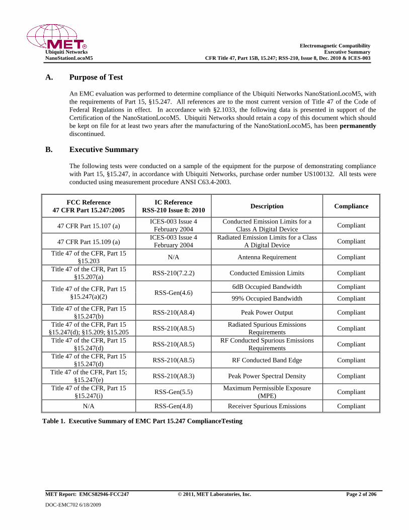
Electromagnetic Compatibility
Ubiquiti Networks Executive Summary
NanoStationLocoM5 CFR Title 47, Part 15B, 15.247; RSS-210, Issue 8, Dec. 2010 & ICES-003
MET Report: EMCS82946-FCC247 © 2011, MET Laboratories, Inc. Page 2 of 206
DOC-EMC702 6/18/2009
A. Purpose of Test
An EMC evaluation was performed to determine compliance of the Ubiquiti Networks NanoStationLocoM5, with
the requirements of Part 15, §15.247. All references are to the most current version of Title 47 of the Code of
Federal Regulations in effect. In accordance with §2.1033, the following data is presented in support of the
Certification of the NanoStationLocoM5. Ubiquiti Networks should retain a copy of this document which should
be kept on file for at least two years after the manufacturing of the NanoStationLocoM5, has been permanently
discontinued.
B. Executive Summary
The following tests were conducted on a sample of the equipment for the purpose of demonstrating compliance
with Part 15, §15.247, in accordance with Ubiquiti Networks, purchase order number US100132. All tests were
conducted using measurement procedure ANSI C63.4-2003.
FCC Reference
47 CFR Part 15.247:2005
IC Reference
RSS-210 Issue 8: 2010 Description Compliance
47 CFR Part 15.107 (a) ICES-003 Issue 4
February 2004
Conducted Emission Limits for a
Class A Digital Device Compliant
47 CFR Part 15.109 (a) ICES-003 Issue 4
February 2004
Radiated Emission Limits for a Class
A Digital Device Compliant
Title 47 of the CFR, Part 15
§15.203 N/A Antenna Requirement Compliant
Title 47 of the CFR, Part 15
§15.207(a) RSS-210(7.2.2) Conducted Emission Limits Compliant
Title 47 of the CFR, Part 15
§15.247(a)(2) RSS-Gen(4.6)
6dB Occupied Bandwidth Compliant
99% Occupied Bandwidth Compliant
Title 47 of the CFR, Part 15
§15.247(b) RSS-210(A8.4) Peak Power Output Compliant
Title 47 of the CFR, Part 15
§15.247(d); §15.209; §15.205 RSS-210(A8.5)
Radiated Spurious Emissions
Requirements Compliant
Title 47 of the CFR, Part 15
§15.247(d) RSS-210(A8.5)
RF Conducted Spurious Emissions
Requirements Compliant
Title 47 of the CFR, Part 15
§15.247(d) RSS-210(A8.5) RF Conducted Band Edge Compliant
Title 47 of the CFR, Part 15;
§15.247(e) RSS-210(A8.3) Peak Power Spectral Density Compliant
Title 47 of the CFR, Part 15
§15.247(i) RSS-Gen(5.5)
Maximum Permissible Exposure
(MPE) Compliant
N/A RSS-Gen(4.8) Receiver Spurious Emissions Compliant
Table 1. Executive Summary of EMC Part 15.247 ComplianceTesting
Electromagnetic Compatibility
Ubiquiti Networks Equipment Configuration
NanoStationLocoM5 CFR Title 47, Part 15B, 15.247; RSS-210, Issue 8, Dec. 2010 & ICES-003
MET Report: EMCS82946-FCC247 © 2011, MET Laboratories, Inc. Page 3 of 206
DOC-EMC702 6/18/2009
II. Equipment Configuration
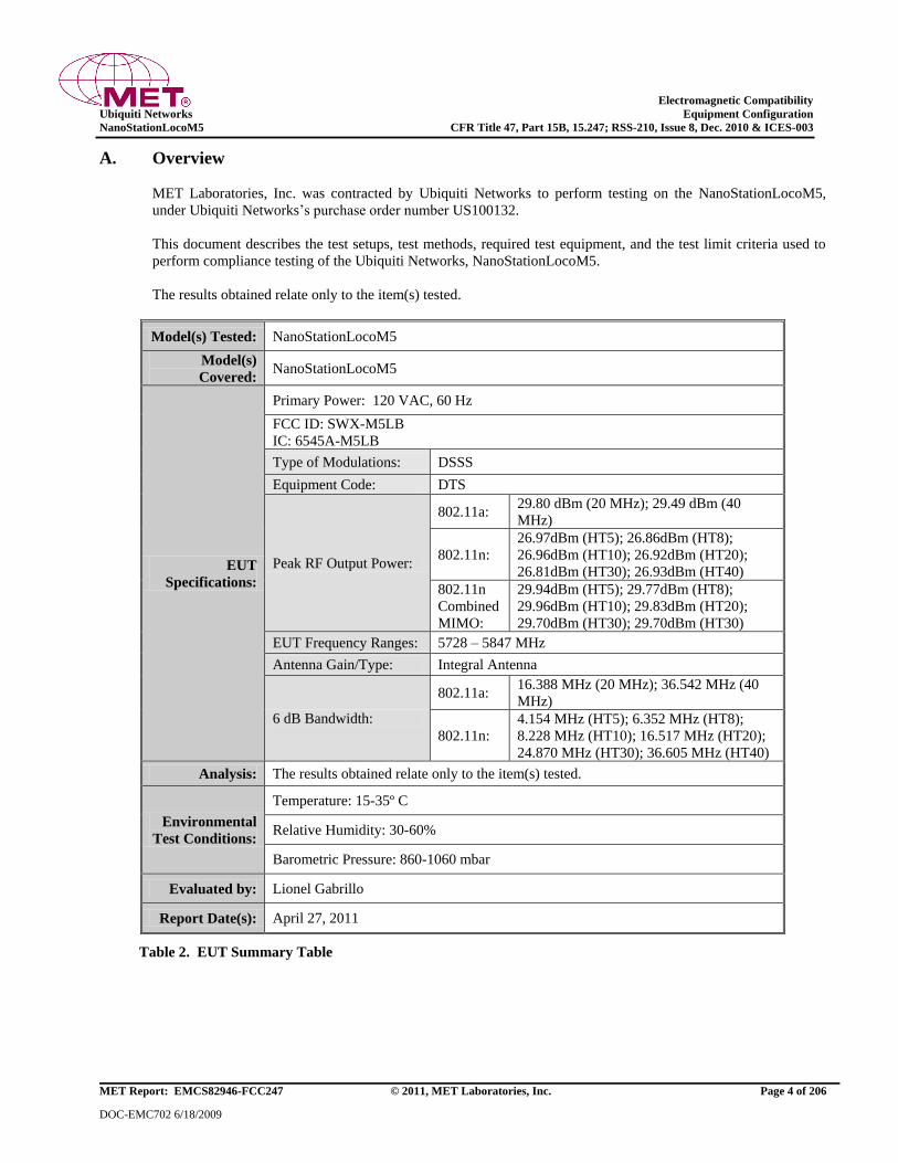
Electromagnetic Compatibility
Ubiquiti Networks Equipment Configuration
NanoStationLocoM5 CFR Title 47, Part 15B, 15.247; RSS-210, Issue 8, Dec. 2010 & ICES-003
MET Report: EMCS82946-FCC247 © 2011, MET Laboratories, Inc. Page 4 of 206
DOC-EMC702 6/18/2009
A. Overview
MET Laboratories, Inc. was contracted by Ubiquiti Networks to perform testing on the NanoStationLocoM5,
under Ubiquiti Networks’s purchase order number US100132.
This document describes the test setups, test methods, required test equipment, and the test limit criteria used to
perform compliance testing of the Ubiquiti Networks, NanoStationLocoM5.
The results obtained relate only to the item(s) tested.
Model(s) Tested: NanoStationLocoM5
Model(s)
Covered: NanoStationLocoM5
EUT
Specifications:
Primary Power: 120 VAC, 60 Hz
FCC ID: SWX-M5LB
IC: 6545A-M5LB
Type of Modulations: DSSS
Equipment Code: DTS
Peak RF Output Power:
802.11a: 29.80 dBm (20 MHz); 29.49 dBm (40
MHz)
802.11n:
26.97dBm (HT5); 26.86dBm (HT8);
26.96dBm (HT10); 26.92dBm (HT20);
26.81dBm (HT30); 26.93dBm (HT40)
802.11n
Combined
MIMO:
29.94dBm (HT5); 29.77dBm (HT8);
29.96dBm (HT10); 29.83dBm (HT20);
29.70dBm (HT30); 29.70dBm (HT30)
EUT Frequency Ranges: 5728 – 5847 MHz
Antenna Gain/Type: Integral Antenna
6 dB Bandwidth:
802.11a: 16.388 MHz (20 MHz); 36.542 MHz (40
MHz)
802.11n:
4.154 MHz (HT5); 6.352 MHz (HT8);
8.228 MHz (HT10); 16.517 MHz (HT20);
24.870 MHz (HT30); 36.605 MHz (HT40)
Analysis: The results obtained relate only to the item(s) tested.
Environmental
Test Conditions:
Temperature: 15-35º C
Relative Humidity: 30-60%
Barometric Pressure: 860-1060 mbar
Evaluated by: Lionel Gabrillo
Report Date(s): April 27, 2011
Table 2. EUT Summary Table
Electromagnetic Compatibility
Ubiquiti Networks Equipment Configuration
NanoStationLocoM5 CFR Title 47, Part 15B, 15.247; RSS-210, Issue 8, Dec. 2010 & ICES-003
MET Report: EMCS82946-FCC247 © 2011, MET Laboratories, Inc. Page 5 of 206
DOC-EMC702 6/18/2009
B. References
CFR 47, Part 15, Subpart C Federal Communication Commission, Code of Federal Regulations, Title 47,
Part 15: General Rules and Regulations, Allocation, Assignment, and Use of
Radio Frequencies
RSS-210, Issue 8, Dec. 2010 Low-power Licence-exempt Radiocommunications Devices (All Frequency
Bands): Category I Equipment
CFR 47, Part 15, Subpart B Electromagnetic Compatibility: Criteria for Radio Frequency Devices
ICES-003, Issue 4 February
2004 Electromagnetic Compatibility: Criteria for Radio Frequency Devices
ANSI C63.4:2003 Methods and Measurements of Radio-Noise Emissions from Low-Voltage
Electrical And Electronic Equipment in the Range of 9 kHz to 40 GHz
ANSI/NCSL Z540-1-1994 Calibration Laboratories and Measuring and Test Equipment - General
Requirements
ANSI/ISO/IEC 17025:2000 General Requirements for the Competence of Testing and Calibration
Laboratories
ANSI C63.10-2009 American National Standard for Testing Unlicensed Wireless Devices
Table 3. References
C. Test Site
All testing was performed at MET Laboratories, Inc., 3162 Belick St., Santa Clara, CA 95054. All equipment
used in making physical determinations is accurate and bears recent traceability to the National Institute of
Standards and Technology.
Radiated Emissions measurements were performed in a 5 meter semi-anechoic chamber (equivalent to an Open
Area Test Site). In accordance with §2.948(a)(3), a complete site description is contained at MET Laboratories.
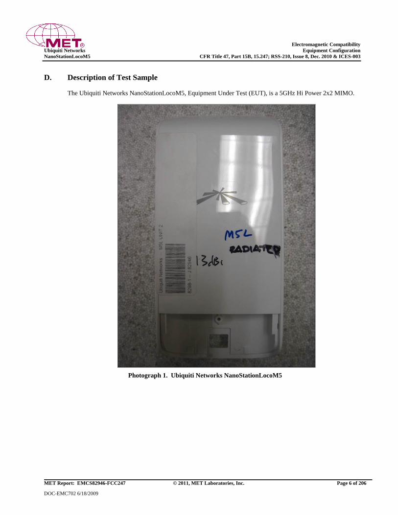
Electromagnetic Compatibility
Ubiquiti Networks Equipment Configuration
NanoStationLocoM5 CFR Title 47, Part 15B, 15.247; RSS-210, Issue 8, Dec. 2010 & ICES-003
MET Report: EMCS82946-FCC247 © 2011, MET Laboratories, Inc. Page 6 of 206
DOC-EMC702 6/18/2009
D. Description of Test Sample
The Ubiquiti Networks NanoStationLocoM5, Equipment Under Test (EUT), is a 5GHz Hi Power 2x2 MIMO.
Photograph 1. Ubiquiti Networks NanoStationLocoM5
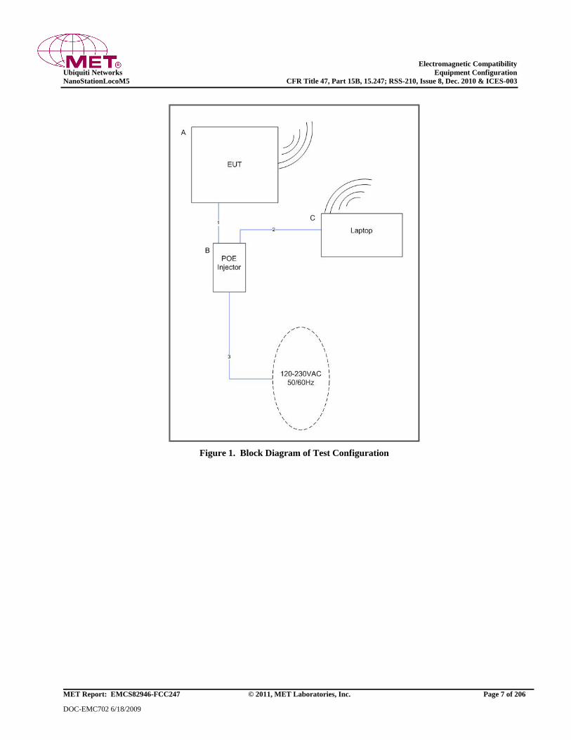
Electromagnetic Compatibility
Ubiquiti Networks Equipment Configuration
NanoStationLocoM5 CFR Title 47, Part 15B, 15.247; RSS-210, Issue 8, Dec. 2010 & ICES-003
MET Report: EMCS82946-FCC247 © 2011, MET Laboratories, Inc. Page 7 of 206
DOC-EMC702 6/18/2009
Figure 1. Block Diagram of Test Configuration
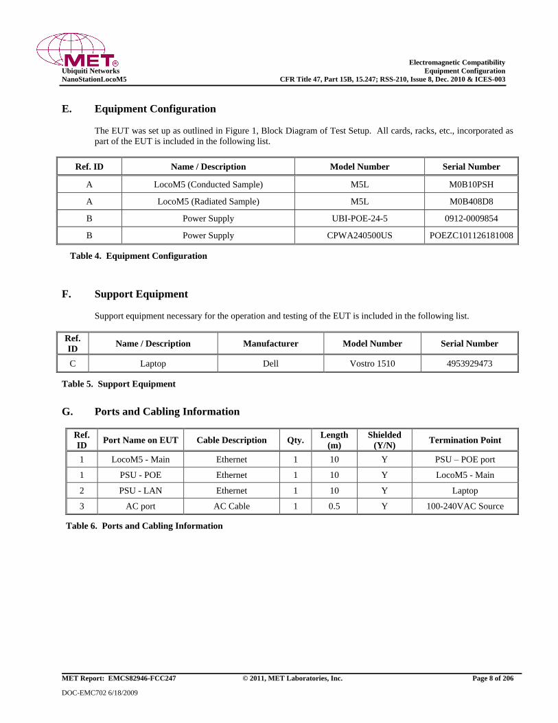
Electromagnetic Compatibility
Ubiquiti Networks Equipment Configuration
NanoStationLocoM5 CFR Title 47, Part 15B, 15.247; RSS-210, Issue 8, Dec. 2010 & ICES-003
MET Report: EMCS82946-FCC247 © 2011, MET Laboratories, Inc. Page 8 of 206
DOC-EMC702 6/18/2009
E. Equipment Configuration
The EUT was set up as outlined in Figure 1, Block Diagram of Test Setup. All cards, racks, etc., incorporated as
part of the EUT is included in the following list.
Ref. ID Name / Description Model Number Serial Number
A LocoM5 (Conducted Sample) M5L M0B10PSH
A LocoM5 (Radiated Sample) M5L M0B408D8
B Power Supply UBI-POE-24-5 0912-0009854
B Power Supply CPWA240500US POEZC101126181008
Table 4. Equipment Configuration
F. Support Equipment
Support equipment necessary for the operation and testing of the EUT is included in the following list.
Ref.
ID Name / Description Manufacturer Model Number Serial Number
C Laptop Dell Vostro 1510 4953929473
Table 5. Support Equipment
G. Ports and Cabling Information
Ref.
ID Port Name on EUT Cable Description Qty.
Length
(m)
Shielded
(Y/N) Termination Point
1 LocoM5 - Main Ethernet 1 10 Y PSU – POE port
1 PSU - POE Ethernet 1 10 Y LocoM5 - Main
2 PSU - LAN Ethernet 1 10 Y Laptop
3 AC port AC Cable 1 0.5 Y 100-240VAC Source
Table 6. Ports and Cabling Information
Electromagnetic Compatibility
Ubiquiti Networks Equipment Configuration
NanoStationLocoM5 CFR Title 47, Part 15B, 15.247; RSS-210, Issue 8, Dec. 2010 & ICES-003
MET Report: EMCS82946-FCC247 © 2011, MET Laboratories, Inc. Page 9 of 206
DOC-EMC702 6/18/2009
H. Mode of Operation
Transmit 6-54Mbps at 5GHz.
I. Method of Monitoring EUT Operation
IP connectivity is maintained with the EUT. If IP connectivity is lost, EUT connectivity shall be re-established
upon power up or re-boot.
J. Modifications
a) Modifications to EUT
No modifications were made to the EUT.
b) Modifications to Test Standard
No modifications were made to the test standard.
K. Disposition of EUT
The test sample including all support equipment submitted to the Electro-Magnetic Compatibility Lab for testing
was returned to Ubiquiti Networks upon completion of testing.
Electromagnetic Compatibility
Ubiquiti Networks Unintentional Radiators
NanoStationLocoM5 CFR Title 47, Part 15B, 15.247; RSS-210, Issue 8, Dec. 2010 & ICES-003
MET Report: EMCS82946-FCC247 © 2011, MET Laboratories, Inc. Page 10 of 206
DOC-EMC702 6/18/2009
III. Electromagnetic Compatibility Criteria
for Unintentional Radiators
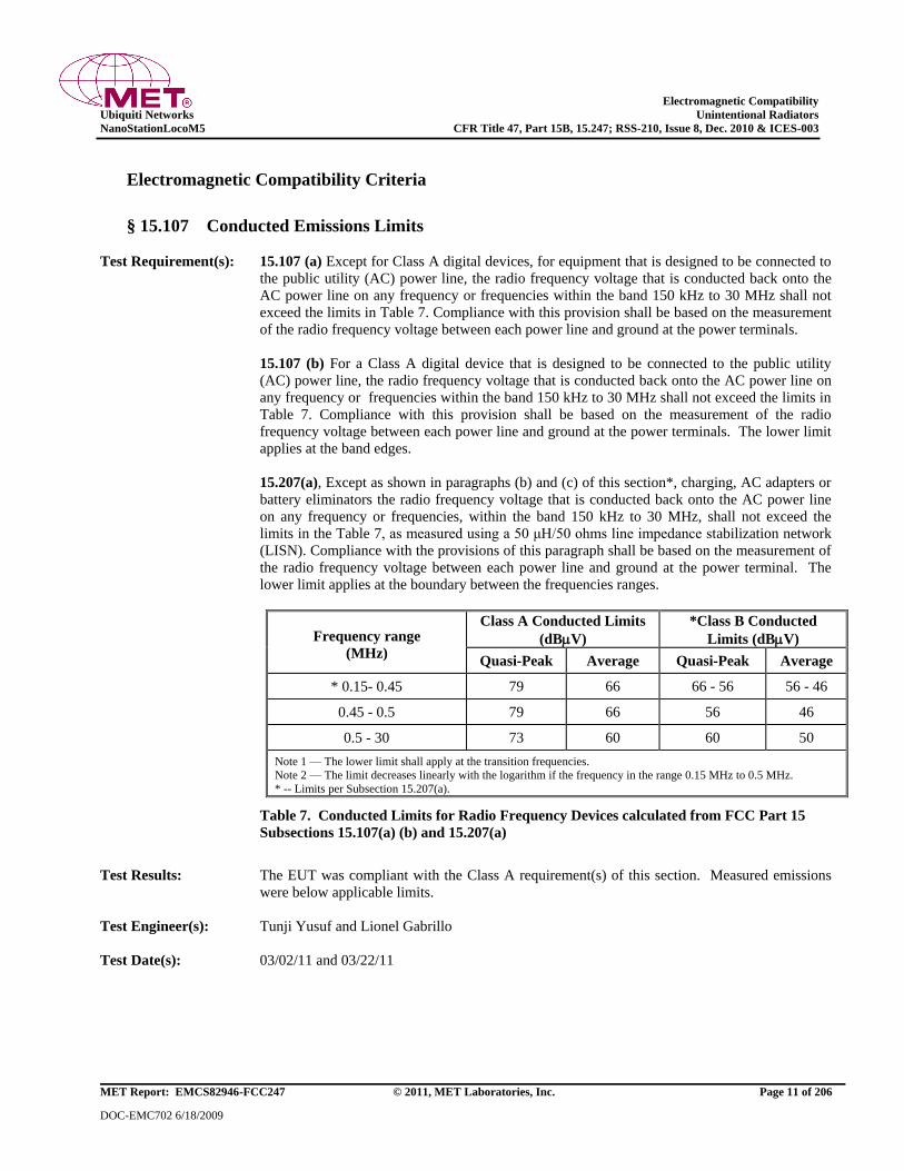
Electromagnetic Compatibility
Ubiquiti Networks Unintentional Radiators
NanoStationLocoM5 CFR Title 47, Part 15B, 15.247; RSS-210, Issue 8, Dec. 2010 & ICES-003
MET Report: EMCS82946-FCC247 © 2011, MET Laboratories, Inc. Page 11 of 206
DOC-EMC702 6/18/2009
Electromagnetic Compatibility Criteria
§ 15.107 Conducted Emissions Limits
Test Requirement(s): 15.107 (a) Except for Class A digital devices, for equipment that is designed to be connected to
the public utility (AC) power line, the radio frequency voltage that is conducted back onto the
AC power line on any frequency or frequencies within the band 150 kHz to 30 MHz shall not
exceed the limits in Table 7. Compliance with this provision shall be based on the measurement
of the radio frequency voltage between each power line and ground at the power terminals.
15.107 (b) For a Class A digital device that is designed to be connected to the public utility
(AC) power line, the radio frequency voltage that is conducted back onto the AC power line on
any frequency or frequencies within the band 150 kHz to 30 MHz shall not exceed the limits in
Table 7. Compliance with this provision shall be based on the measurement of the radio
frequency voltage between each power line and ground at the power terminals. The lower limit
applies at the band edges.
15.207(a), Except as shown in paragraphs (b) and (c) of this section*, charging, AC adapters or
battery eliminators the radio frequency voltage that is conducted back onto the AC power line
on any frequency or frequencies, within the band 150 kHz to 30 MHz, shall not exceed the
limits in the Table 7, as measured using a 50 μH/50 ohms line impedance stabilization network
(LISN). Compliance with the provisions of this paragraph shall be based on the measurement of
the radio frequency voltage between each power line and ground at the power terminal. The
lower limit applies at the boundary between the frequencies ranges.
Frequency range
(MHz)
Class A Conducted Limits
(dBV) *Class B Conducted
Limits (dBV)
Quasi-Peak Average Quasi-Peak Average
* 0.15- 0.45 79 66 66 - 56 56 - 46
0.45 - 0.5 79 66 56 46
0.5 - 30 73 60 60 50
Note 1 — The lower limit shall apply at the transition frequencies.
Note 2 — The limit decreases linearly with the logarithm if the frequency in the range 0.15 MHz to 0.5 MHz.
* -- Limits per Subsection 15.207(a).
Table 7. Conducted Limits for Radio Frequency Devices calculated from FCC Part 15
Subsections 15.107(a) (b) and 15.207(a)
Test Results: The EUT was compliant with the Class A requirement(s) of this section. Measured emissions
were below applicable limits.
Test Engineer(s): Tunji Yusuf and Lionel Gabrillo
Test Date(s): 03/02/11 and 03/22/11
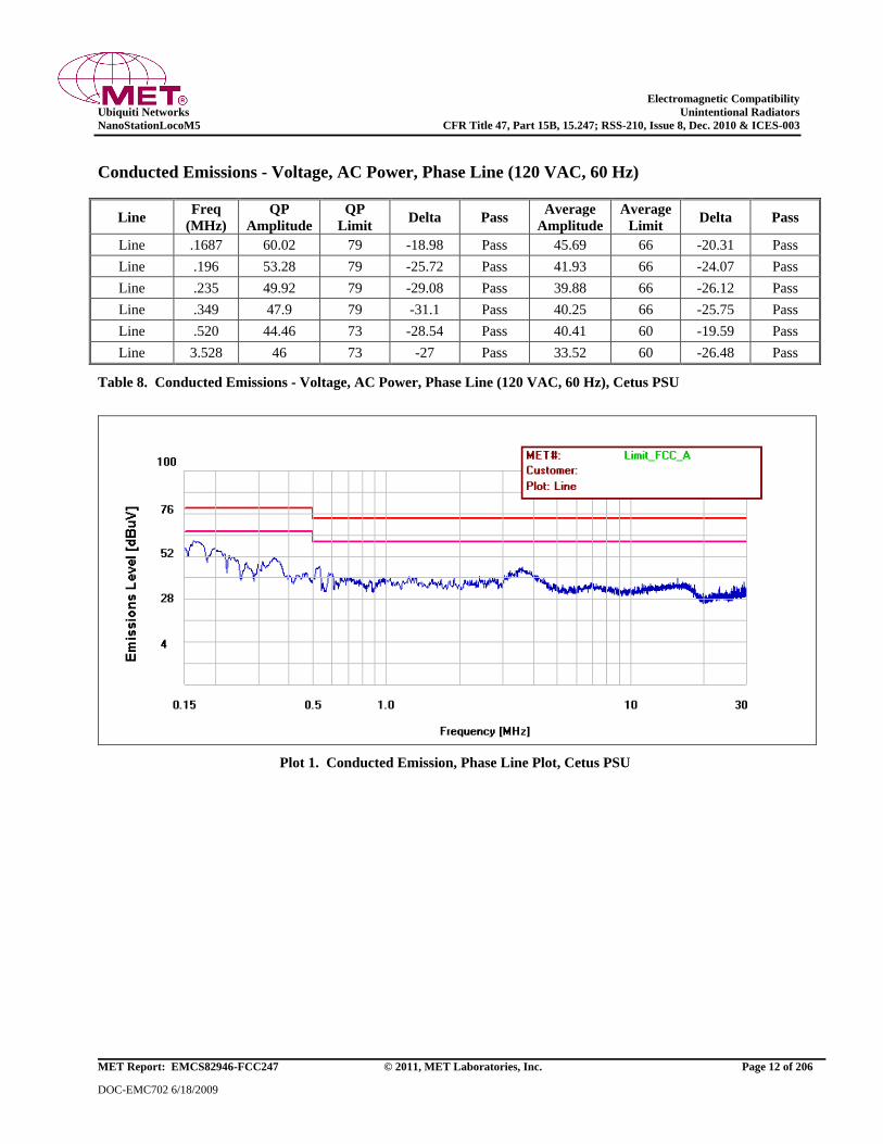
Electromagnetic Compatibility
Ubiquiti Networks Unintentional Radiators
NanoStationLocoM5 CFR Title 47, Part 15B, 15.247; RSS-210, Issue 8, Dec. 2010 & ICES-003
MET Report: EMCS82946-FCC247 © 2011, MET Laboratories, Inc. Page 12 of 206
DOC-EMC702 6/18/2009
Conducted Emissions - Voltage, AC Power, Phase Line (120 VAC, 60 Hz)
Line Freq
(MHz)
QP
Amplitude
QP
Limit Delta Pass
Average
Amplitude
Average
Limit Delta Pass
Line .1687 60.02 79 -18.98 Pass 45.69 66 -20.31 Pass
Line .196 53.28 79 -25.72 Pass 41.93 66 -24.07 Pass
Line .235 49.92 79 -29.08 Pass 39.88 66 -26.12 Pass
Line .349 47.9 79 -31.1 Pass 40.25 66 -25.75 Pass
Line .520 44.46 73 -28.54 Pass 40.41 60 -19.59 Pass
Line 3.528 46 73 -27 Pass 33.52 60 -26.48 Pass
Table 8. Conducted Emissions - Voltage, AC Power, Phase Line (120 VAC, 60 Hz), Cetus PSU
Plot 1. Conducted Emission, Phase Line Plot, Cetus PSU
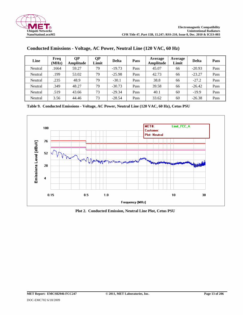
Electromagnetic Compatibility
Ubiquiti Networks Unintentional Radiators
NanoStationLocoM5 CFR Title 47, Part 15B, 15.247; RSS-210, Issue 8, Dec. 2010 & ICES-003
MET Report: EMCS82946-FCC247 © 2011, MET Laboratories, Inc. Page 13 of 206
DOC-EMC702 6/18/2009
Conducted Emissions - Voltage, AC Power, Neutral Line (120 VAC, 60 Hz)
Line Freq
(MHz)
QP
Amplitude
QP
Limit Delta Pass
Average
Amplitude
Average
Limit Delta Pass
Neutral .1664 59.27 79 -19.73 Pass 45.07 66 -20.93 Pass
Neutral .199 53.02 79 -25.98 Pass 42.73 66 -23.27 Pass
Neutral .235 48.9 79 -30.1 Pass 38.8 66 -27.2 Pass
Neutral .349 48.27 79 -30.73 Pass 39.58 66 -26.42 Pass
Neutral .519 43.66 73 -29.34 Pass 40.1 60 -19.9 Pass
Neutral 3.56 44.46 73 -28.54 Pass 33.62 60 -26.38 Pass
Table 9. Conducted Emissions - Voltage, AC Power, Neutral Line (120 VAC, 60 Hz), Cetus PSU
Plot 2. Conducted Emission, Neutral Line Plot, Cetus PSU
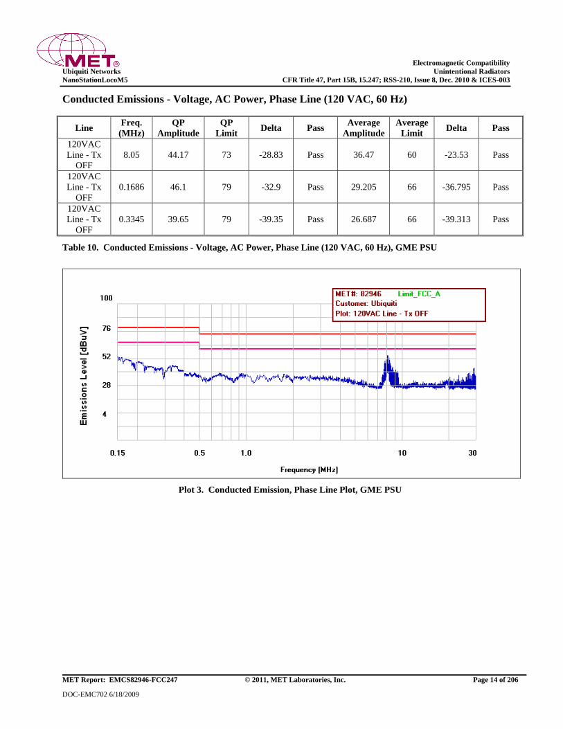
Electromagnetic Compatibility
Ubiquiti Networks Unintentional Radiators
NanoStationLocoM5 CFR Title 47, Part 15B, 15.247; RSS-210, Issue 8, Dec. 2010 & ICES-003
MET Report: EMCS82946-FCC247 © 2011, MET Laboratories, Inc. Page 14 of 206
DOC-EMC702 6/18/2009
Conducted Emissions - Voltage, AC Power, Phase Line (120 VAC, 60 Hz)
Line Freq.
(MHz)
QP
Amplitude
QP
Limit Delta Pass
Average
Amplitude
Average
Limit Delta Pass
120VAC
Line - Tx
OFF
8.05 44.17 73 -28.83 Pass 36.47 60 -23.53 Pass
120VAC
Line - Tx
OFF
0.1686 46.1 79 -32.9 Pass 29.205 66 -36.795 Pass
120VAC
Line - Tx
OFF
0.3345 39.65 79 -39.35 Pass 26.687 66 -39.313 Pass
Table 10. Conducted Emissions - Voltage, AC Power, Phase Line (120 VAC, 60 Hz), GME PSU
Plot 3. Conducted Emission, Phase Line Plot, GME PSU
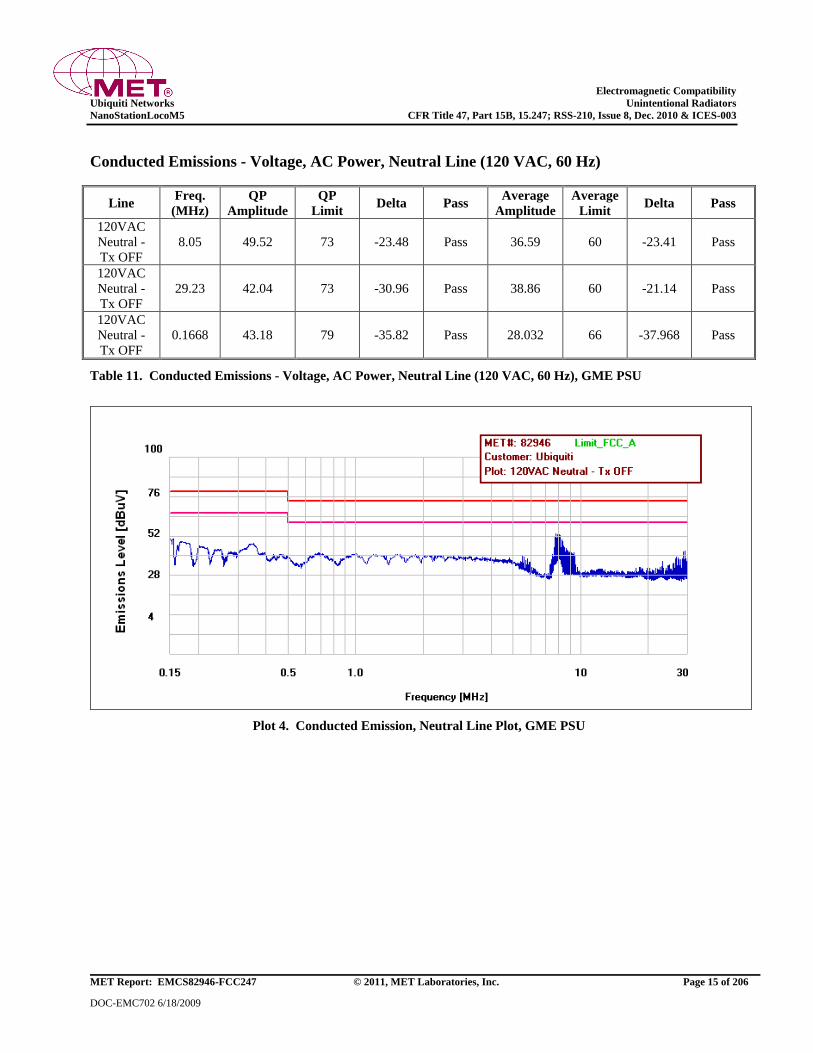
Electromagnetic Compatibility
Ubiquiti Networks Unintentional Radiators
NanoStationLocoM5 CFR Title 47, Part 15B, 15.247; RSS-210, Issue 8, Dec. 2010 & ICES-003
MET Report: EMCS82946-FCC247 © 2011, MET Laboratories, Inc. Page 15 of 206
DOC-EMC702 6/18/2009
Conducted Emissions - Voltage, AC Power, Neutral Line (120 VAC, 60 Hz)
Line Freq.
(MHz)
QP
Amplitude
QP
Limit Delta Pass
Average
Amplitude
Average
Limit Delta Pass
120VAC
Neutral -
Tx OFF
8.05 49.52 73 -23.48 Pass 36.59 60 -23.41 Pass
120VAC
Neutral -
Tx OFF
29.23 42.04 73 -30.96 Pass 38.86 60 -21.14 Pass
120VAC
Neutral -
Tx OFF
0.1668 43.18 79 -35.82 Pass 28.032 66 -37.968 Pass
Table 11. Conducted Emissions - Voltage, AC Power, Neutral Line (120 VAC, 60 Hz), GME PSU
Plot 4. Conducted Emission, Neutral Line Plot, GME PSU
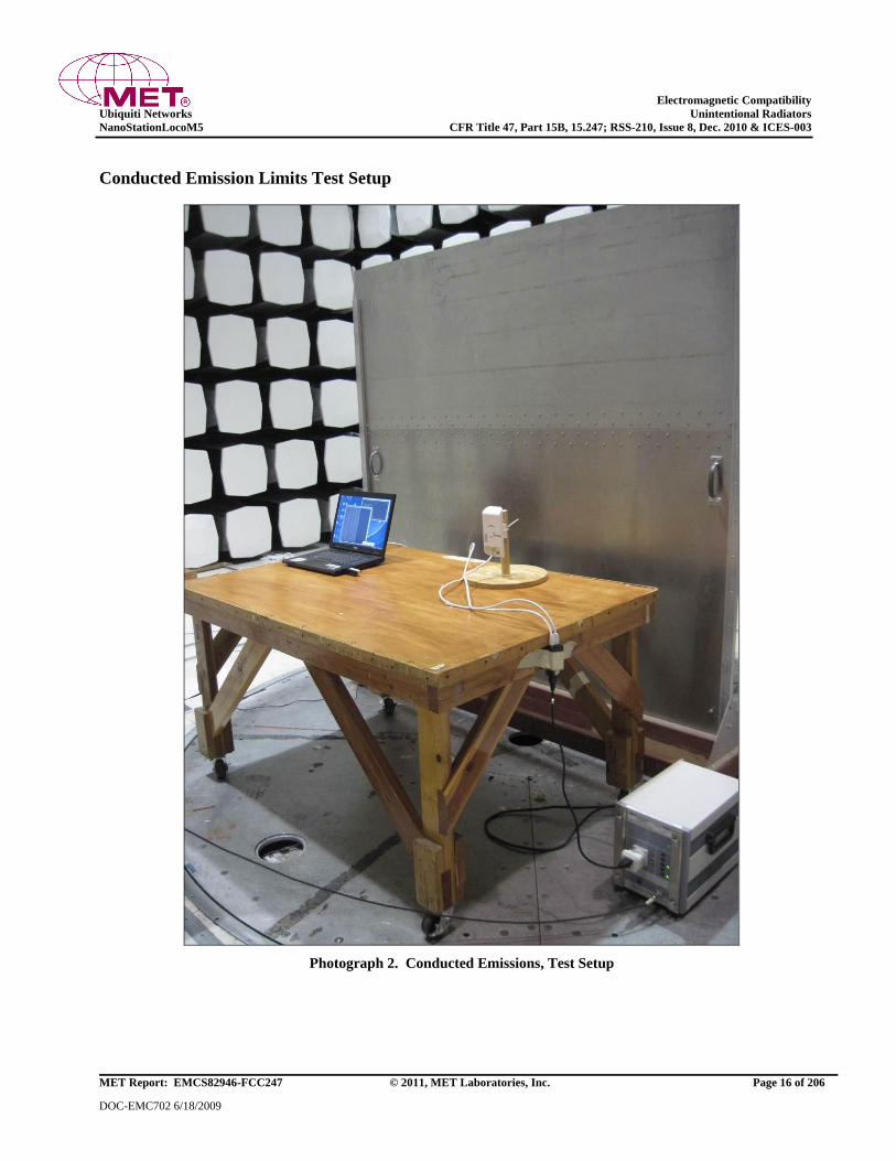
Electromagnetic Compatibility
Ubiquiti Networks Unintentional Radiators
NanoStationLocoM5 CFR Title 47, Part 15B, 15.247; RSS-210, Issue 8, Dec. 2010 & ICES-003
MET Report: EMCS82946-FCC247 © 2011, MET Laboratories, Inc. Page 16 of 206
DOC-EMC702 6/18/2009
Conducted Emission Limits Test Setup
Photograph 2. Conducted Emissions, Test Setup
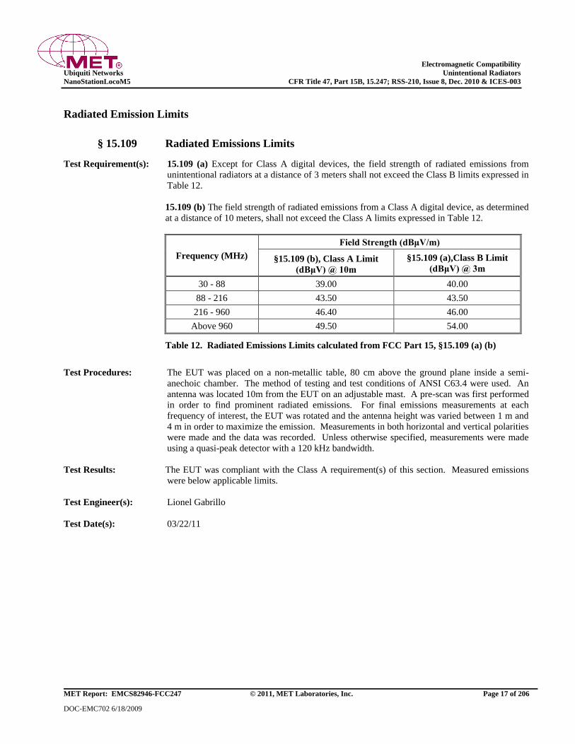
Electromagnetic Compatibility
Ubiquiti Networks Unintentional Radiators
NanoStationLocoM5 CFR Title 47, Part 15B, 15.247; RSS-210, Issue 8, Dec. 2010 & ICES-003
MET Report: EMCS82946-FCC247 © 2011, MET Laboratories, Inc. Page 17 of 206
DOC-EMC702 6/18/2009
Radiated Emission Limits
§ 15.109 Radiated Emissions Limits
Test Requirement(s): 15.109 (a) Except for Class A digital devices, the field strength of radiated emissions from
unintentional radiators at a distance of 3 meters shall not exceed the Class B limits expressed in
Table 12.
15.109 (b) The field strength of radiated emissions from a Class A digital device, as determined
at a distance of 10 meters, shall not exceed the Class A limits expressed in Table 12.
Frequency (MHz)
Field Strength (dBμV/m)
§15.109 (b), Class A Limit
(dBμV) @ 10m
§15.109 (a),Class B Limit
(dBμV) @ 3m
30 - 88 39.00 40.00
88 - 216 43.50 43.50
216 - 960 46.40 46.00
Above 960 49.50 54.00
Table 12. Radiated Emissions Limits calculated from FCC Part 15, §15.109 (a) (b)
Test Procedures: The EUT was placed on a non-metallic table, 80 cm above the ground plane inside a semi-
anechoic chamber. The method of testing and test conditions of ANSI C63.4 were used. An
antenna was located 10m from the EUT on an adjustable mast. A pre-scan was first performed
in order to find prominent radiated emissions. For final emissions measurements at each
frequency of interest, the EUT was rotated and the antenna height was varied between 1 m and
4 m in order to maximize the emission. Measurements in both horizontal and vertical polarities
were made and the data was recorded. Unless otherwise specified, measurements were made
using a quasi-peak detector with a 120 kHz bandwidth.
Test Results: The EUT was compliant with the Class A requirement(s) of this section. Measured emissions
were below applicable limits.
Test Engineer(s): Lionel Gabrillo
Test Date(s): 03/22/11

Electromagnetic Compatibility
Ubiquiti Networks Unintentional Radiators
NanoStationLocoM5 CFR Title 47, Part 15B, 15.247; RSS-210, Issue 8, Dec. 2010 & ICES-003
MET Report: EMCS82946-FCC247 © 2011, MET Laboratories, Inc. Page 18 of 206
DOC-EMC702 6/18/2009
Radiated Emissions Limits Test Results, Class A
Frequency
(MHz)
Antenna
Polarity
EUT
Azimuth
(Degrees)
Antenna
Height
(cm)
Uncorrected
Amplitude
(dBuV)
ACF
(dB/m)
Pre
Amp
Gain
(dB)
CBL
(dB)
DCF
(dB)
Corrected
Amplitude
(dBuV)
Limit
(dBuV)
Margin
(dB)
87.48 V 118.3 135.4 58.86 8.996 40 1.492 0 29.348 39 -9.652
73.32 V 309.9 241.3 51.48 5.832 40 1.31 0 18.622 39 -20.378
36.04 V 37.0 100.0 45.94 13.676 40 0.953 0 20.569 39 -18.431
779.98 V 166.0 171.5 41.12 20.1 40 4.693 0 25.913 46.4 -20.487
779.98 H 305.8 100.0 42.75 19.799 40 4.693 0 27.242 46.4 -19.158
389.97 H 24.3 228.5 44.03 14.9 40 3.261 0 22.191 46.4 -24.209
Table 13. Radiated Emissions Limits, Test Results, Cetus PSU, FCC Limits
Plot 5. Radiated Emissions, 30 MHz - 1 GHz, Cetus PSU, FCC Limits
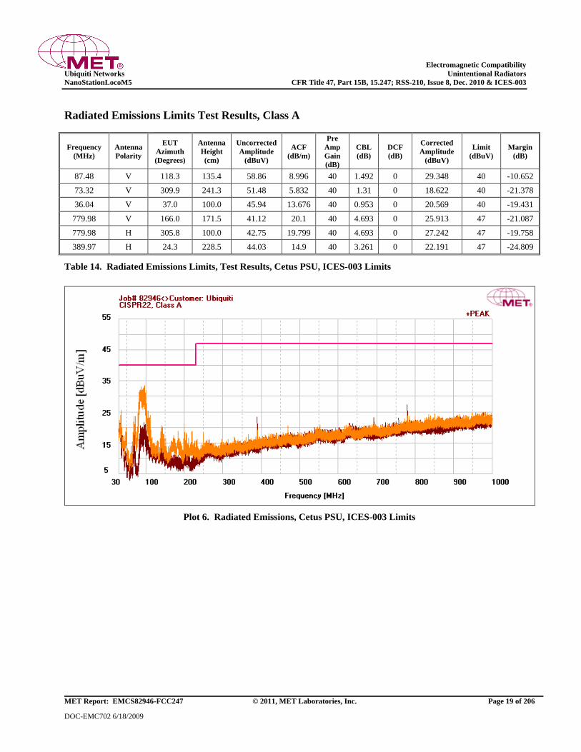
Electromagnetic Compatibility
Ubiquiti Networks Unintentional Radiators
NanoStationLocoM5 CFR Title 47, Part 15B, 15.247; RSS-210, Issue 8, Dec. 2010 & ICES-003
MET Report: EMCS82946-FCC247 © 2011, MET Laboratories, Inc. Page 19 of 206
DOC-EMC702 6/18/2009
Radiated Emissions Limits Test Results, Class A
Frequency
(MHz)
Antenna
Polarity
EUT
Azimuth
(Degrees)
Antenna
Height
(cm)
Uncorrected
Amplitude
(dBuV)
ACF
(dB/m)
Pre
Amp
Gain
(dB)
CBL
(dB)
DCF
(dB)
Corrected
Amplitude
(dBuV)
Limit
(dBuV)
Margin
(dB)
87.48 V 118.3 135.4 58.86 8.996 40 1.492 0 29.348 40 -10.652
73.32 V 309.9 241.3 51.48 5.832 40 1.31 0 18.622 40 -21.378
36.04 V 37.0 100.0 45.94 13.676 40 0.953 0 20.569 40 -19.431
779.98 V 166.0 171.5 41.12 20.1 40 4.693 0 25.913 47 -21.087
779.98 H 305.8 100.0 42.75 19.799 40 4.693 0 27.242 47 -19.758
389.97 H 24.3 228.5 44.03 14.9 40 3.261 0 22.191 47 -24.809
Table 14. Radiated Emissions Limits, Test Results, Cetus PSU, ICES-003 Limits
Plot 6. Radiated Emissions, Cetus PSU, ICES-003 Limits
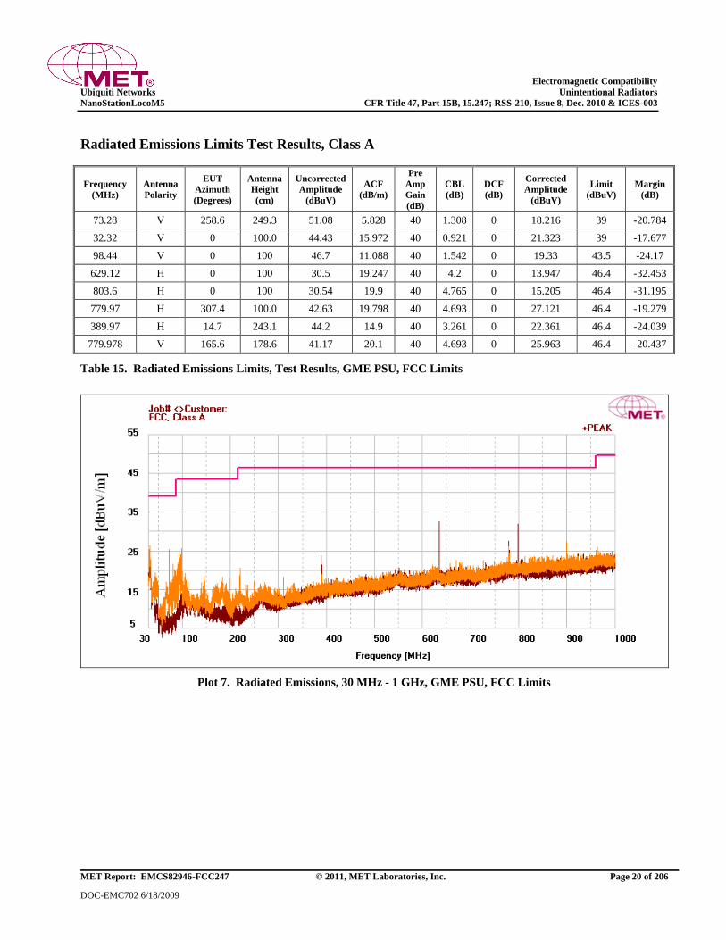
Electromagnetic Compatibility
Ubiquiti Networks Unintentional Radiators
NanoStationLocoM5 CFR Title 47, Part 15B, 15.247; RSS-210, Issue 8, Dec. 2010 & ICES-003
MET Report: EMCS82946-FCC247 © 2011, MET Laboratories, Inc. Page 20 of 206
DOC-EMC702 6/18/2009
Radiated Emissions Limits Test Results, Class A
Frequency
(MHz)
Antenna
Polarity
EUT
Azimuth
(Degrees)
Antenna
Height
(cm)
Uncorrected
Amplitude
(dBuV)
ACF
(dB/m)
Pre
Amp
Gain
(dB)
CBL
(dB)
DCF
(dB)
Corrected
Amplitude
(dBuV)
Limit
(dBuV)
Margin
(dB)
73.28 V 258.6 249.3 51.08 5.828 40 1.308 0 18.216 39 -20.784
32.32 V 0 100.0 44.43 15.972 40 0.921 0 21.323 39 -17.677
98.44 V 0 100 46.7 11.088 40 1.542 0 19.33 43.5 -24.17
629.12 H 0 100 30.5 19.247 40 4.2 0 13.947 46.4 -32.453
803.6 H 0 100 30.54 19.9 40 4.765 0 15.205 46.4 -31.195
779.97 H 307.4 100.0 42.63 19.798 40 4.693 0 27.121 46.4 -19.279
389.97 H 14.7 243.1 44.2 14.9 40 3.261 0 22.361 46.4 -24.039
779.978 V 165.6 178.6 41.17 20.1 40 4.693 0 25.963 46.4 -20.437
Table 15. Radiated Emissions Limits, Test Results, GME PSU, FCC Limits
Plot 7. Radiated Emissions, 30 MHz - 1 GHz, GME PSU, FCC Limits
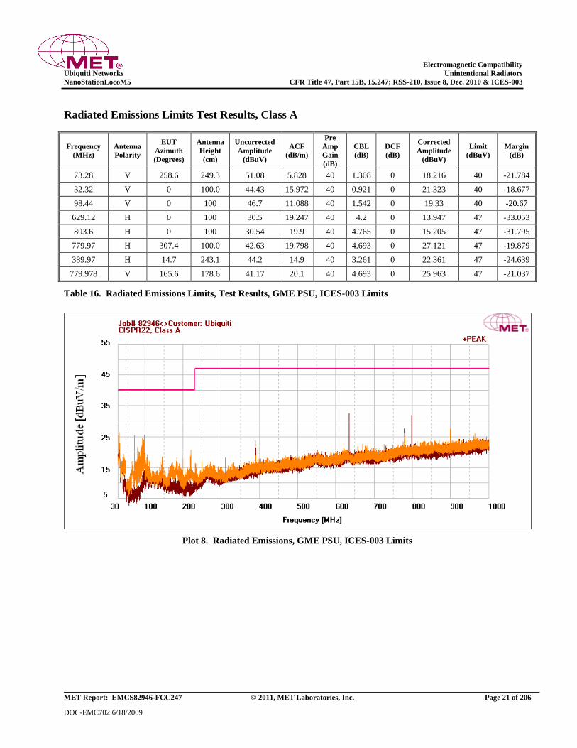
Electromagnetic Compatibility
Ubiquiti Networks Unintentional Radiators
NanoStationLocoM5 CFR Title 47, Part 15B, 15.247; RSS-210, Issue 8, Dec. 2010 & ICES-003
MET Report: EMCS82946-FCC247 © 2011, MET Laboratories, Inc. Page 21 of 206
DOC-EMC702 6/18/2009
Radiated Emissions Limits Test Results, Class A
Frequency
(MHz)
Antenna
Polarity
EUT
Azimuth
(Degrees)
Antenna
Height
(cm)
Uncorrected
Amplitude
(dBuV)
ACF
(dB/m)
Pre
Amp
Gain
(dB)
CBL
(dB)
DCF
(dB)
Corrected
Amplitude
(dBuV)
Limit
(dBuV)
Margin
(dB)
73.28 V 258.6 249.3 51.08 5.828 40 1.308 0 18.216 40 -21.784
32.32 V 0 100.0 44.43 15.972 40 0.921 0 21.323 40 -18.677
98.44 V 0 100 46.7 11.088 40 1.542 0 19.33 40 -20.67
629.12 H 0 100 30.5 19.247 40 4.2 0 13.947 47 -33.053
803.6 H 0 100 30.54 19.9 40 4.765 0 15.205 47 -31.795
779.97 H 307.4 100.0 42.63 19.798 40 4.693 0 27.121 47 -19.879
389.97 H 14.7 243.1 44.2 14.9 40 3.261 0 22.361 47 -24.639
779.978 V 165.6 178.6 41.17 20.1 40 4.693 0 25.963 47 -21.037
Table 16. Radiated Emissions Limits, Test Results, GME PSU, ICES-003 Limits
Plot 8. Radiated Emissions, GME PSU, ICES-003 Limits
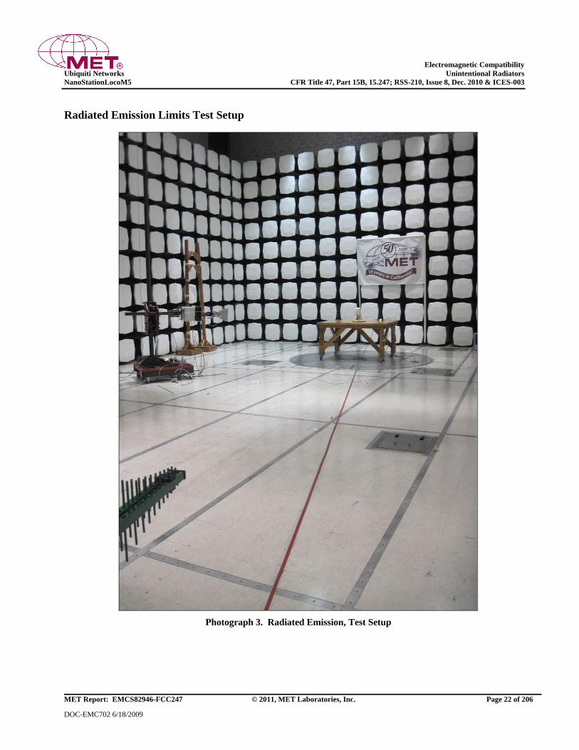
Electromagnetic Compatibility
Ubiquiti Networks Unintentional Radiators
NanoStationLocoM5 CFR Title 47, Part 15B, 15.247; RSS-210, Issue 8, Dec. 2010 & ICES-003
MET Report: EMCS82946-FCC247 © 2011, MET Laboratories, Inc. Page 22 of 206
DOC-EMC702 6/18/2009
Radiated Emission Limits Test Setup
Photograph 3. Radiated Emission, Test Setup
Electromagnetic Compatibility
Ubiquiti Networks Intentional Radiators
NanoStationLocoM5 CFR Title 47, Part 15B, 15.247; RSS-210, Issue 8, Dec. 2010 & ICES-003
MET Report: EMCS82946-FCC247 © 2011, MET Laboratories, Inc. Page 23 of 206
DOC-EMC702 6/18/2009
IV. Electromagnetic Compatibility Criteria
for Intentional Radiators
Electromagnetic Compatibility
Ubiquiti Networks Intentional Radiators
NanoStationLocoM5 CFR Title 47, Part 15B, 15.247; RSS-210, Issue 8, Dec. 2010 & ICES-003
MET Report: EMCS82946-FCC247 © 2011, MET Laboratories, Inc. Page 24 of 206
DOC-EMC702 6/18/2009
Electromagnetic Compatibility Criteria for Intentional Radiators
§ 15.203 Antenna Requirement
Test Requirement: § 15.203: An intentional radiator shall be designed to ensure that no antenna other than that
furnished by the responsible party shall be used with the device. The use of a permanently
attached antenna or of an antenna that uses a unique coupling to the intentional radiator shall be
considered sufficient to comply with the provisions of this section. The manufacturer may
design the unit so that a broken antenna can be replaced by the user, but the use of a standard
antenna jack or electrical connector is prohibited.
The structure and application of the EUT were analyzed to determine compliance with Section
15.203 of the Rules. Section 15.203 states that the subject device must meet at least one of the
following criteria:
a.) Antenna must be permanently attached to the unit.
b.) Antenna must use a unique type of connector to attach to the EUT.
c.) Unit must be professionally installed. Installer shall be responsible for verifying
that the correct antenna is employed with the unit.
Results: The EUT as tested is compliant the criteria of §15.203. The EUT has an integral antenna.
Test Engineer(s): Lionel Gabrillo
Test Date(s): 03/16/11
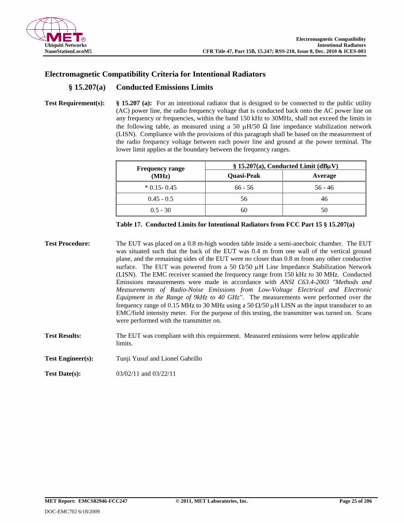
Electromagnetic Compatibility
Ubiquiti Networks Intentional Radiators
NanoStationLocoM5 CFR Title 47, Part 15B, 15.247; RSS-210, Issue 8, Dec. 2010 & ICES-003
MET Report: EMCS82946-FCC247 © 2011, MET Laboratories, Inc. Page 25 of 206
DOC-EMC702 6/18/2009
Electromagnetic Compatibility Criteria for Intentional Radiators
§ 15.207(a) Conducted Emissions Limits
Test Requirement(s): § 15.207 (a): For an intentional radiator that is designed to be connected to the public utility
(AC) power line, the radio frequency voltage that is conducted back onto the AC power line on
any frequency or frequencies, within the band 150 kHz to 30MHz, shall not exceed the limits in
the following table, as measured using a 50 H/50 line impedance stabilization network
(LISN). Compliance with the provisions of this paragraph shall be based on the measurement of
the radio frequency voltage between each power line and ground at the power terminal. The
lower limit applies at the boundary between the frequency ranges.
Frequency range
(MHz)
§ 15.207(a), Conducted Limit (dBV)
Quasi-Peak Average
* 0.15- 0.45 66 - 56 56 - 46
0.45 - 0.5 56 46
0.5 - 30 60 50
Table 17. Conducted Limits for Intentional Radiators from FCC Part 15 § 15.207(a)
Test Procedure: The EUT was placed on a 0.8 m-high wooden table inside a semi-anechoic chamber. The EUT
was situated such that the back of the EUT was 0.4 m from one wall of the vertical ground
plane, and the remaining sides of the EUT were no closer than 0.8 m from any other conductive
surface. The EUT was powered from a 50 /50 H Line Impedance Stabilization Network
(LISN). The EMC receiver scanned the frequency range from 150 kHz to 30 MHz. Conducted
Emissions measurements were made in accordance with ANSI C63.4-2003 "Methods and
Measurements of Radio-Noise Emissions from Low-Voltage Electrical and Electronic
Equipment in the Range of 9kHz to 40 GHz". The measurements were performed over the
frequency range of 0.15 MHz to 30 MHz using a 50 /50 H LISN as the input transducer to an
EMC/field intensity meter. For the purpose of this testing, the transmitter was turned on. Scans
were performed with the transmitter on.
Test Results: The EUT was compliant with this requirement. Measured emissions were below applicable
limits.
Test Engineer(s): Tunji Yusuf and Lionel Gabrillo
Test Date(s): 03/02/11 and 03/22/11
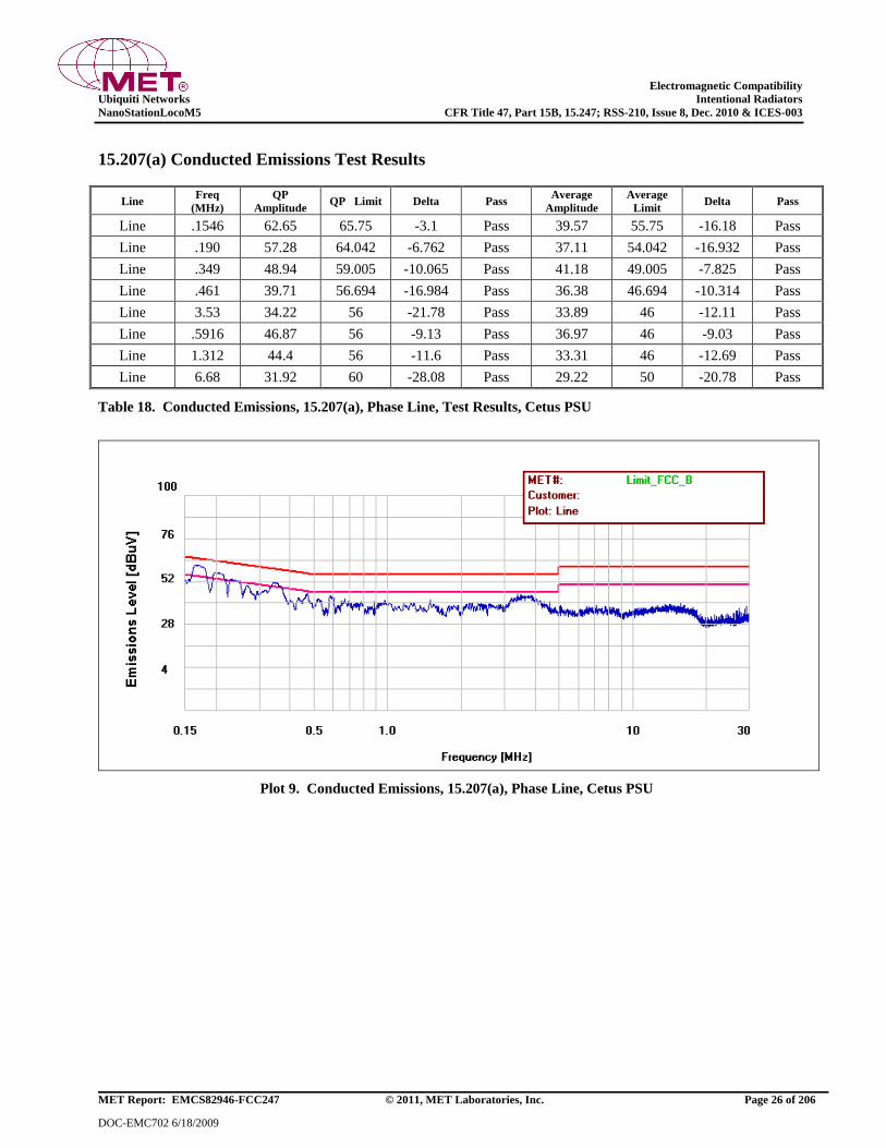
Electromagnetic Compatibility
Ubiquiti Networks Intentional Radiators
NanoStationLocoM5 CFR Title 47, Part 15B, 15.247; RSS-210, Issue 8, Dec. 2010 & ICES-003
MET Report: EMCS82946-FCC247 © 2011, MET Laboratories, Inc. Page 26 of 206
DOC-EMC702 6/18/2009
15.207(a) Conducted Emissions Test Results
Line Freq
(MHz)
QP
Amplitude QP Limit Delta Pass
Average
Amplitude
Average
Limit Delta Pass
Line .1546 62.65 65.75 -3.1 Pass 39.57 55.75 -16.18 Pass
Line .190 57.28 64.042 -6.762 Pass 37.11 54.042 -16.932 Pass
Line .349 48.94 59.005 -10.065 Pass 41.18 49.005 -7.825 Pass
Line .461 39.71 56.694 -16.984 Pass 36.38 46.694 -10.314 Pass
Line 3.53 34.22 56 -21.78 Pass 33.89 46 -12.11 Pass
Line .5916 46.87 56 -9.13 Pass 36.97 46 -9.03 Pass
Line 1.312 44.4 56 -11.6 Pass 33.31 46 -12.69 Pass
Line 6.68 31.92 60 -28.08 Pass 29.22 50 -20.78 Pass
Table 18. Conducted Emissions, 15.207(a), Phase Line, Test Results, Cetus PSU
Plot 9. Conducted Emissions, 15.207(a), Phase Line, Cetus PSU
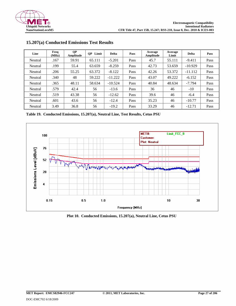
Electromagnetic Compatibility
Ubiquiti Networks Intentional Radiators
NanoStationLocoM5 CFR Title 47, Part 15B, 15.247; RSS-210, Issue 8, Dec. 2010 & ICES-003
MET Report: EMCS82946-FCC247 © 2011, MET Laboratories, Inc. Page 27 of 206
DOC-EMC702 6/18/2009
15.207(a) Conducted Emissions Test Results
Line Freq
(MHz)
QP
Amplitude QP Limit Delta Pass
Average
Amplitude
Average
Limit Delta Pass
Neutral .167 59.91 65.111 -5.201 Pass 45.7 55.111 -9.411 Pass
Neutral .199 55.4 63.659 -8.259 Pass 42.73 53.659 -10.929 Pass
Neutral .206 55.25 63.372 -8.122 Pass 42.26 53.372 -11.112 Pass
Neutral .340 48 59.222 -11.222 Pass 43.07 49.222 -6.152 Pass
Neutral .365 48.11 58.634 -10.524 Pass 40.84 48.634 -7.794 Pass
Neutral .579 42.4 56 -13.6 Pass 36 46 -10 Pass
Neutral .519 43.38 56 -12.62 Pass 39.6 46 -6.4 Pass
Neutral .601 43.6 56 -12.4 Pass 35.23 46 -10.77 Pass
Neutral 3.49 36.8 56 -19.2 Pass 33.29 46 -12.71 Pass
Table 19. Conducted Emissions, 15.207(a), Neutral Line, Test Results, Cetus PSU
Plot 10. Conducted Emissions, 15.207(a), Neutral Line, Cetus PSU
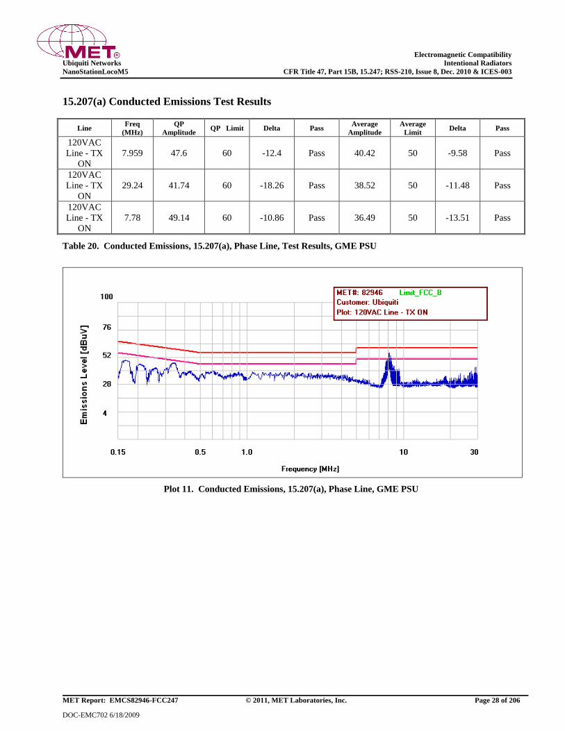
Electromagnetic Compatibility
Ubiquiti Networks Intentional Radiators
NanoStationLocoM5 CFR Title 47, Part 15B, 15.247; RSS-210, Issue 8, Dec. 2010 & ICES-003
MET Report: EMCS82946-FCC247 © 2011, MET Laboratories, Inc. Page 28 of 206
DOC-EMC702 6/18/2009
15.207(a) Conducted Emissions Test Results
Line Freq
(MHz)
QP
Amplitude QP Limit Delta Pass
Average
Amplitude
Average
Limit Delta Pass
120VAC
Line - TX
ON
7.959 47.6 60 -12.4 Pass 40.42 50 -9.58 Pass
120VAC
Line - TX
ON
29.24 41.74 60 -18.26 Pass 38.52 50 -11.48 Pass
120VAC
Line - TX
ON
7.78 49.14 60 -10.86 Pass 36.49 50 -13.51 Pass
Table 20. Conducted Emissions, 15.207(a), Phase Line, Test Results, GME PSU
Plot 11. Conducted Emissions, 15.207(a), Phase Line, GME PSU
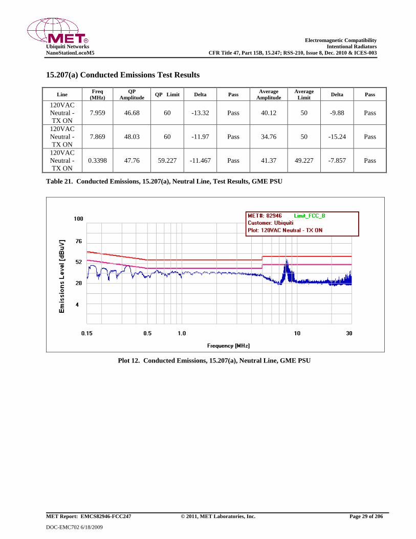
Electromagnetic Compatibility
Ubiquiti Networks Intentional Radiators
NanoStationLocoM5 CFR Title 47, Part 15B, 15.247; RSS-210, Issue 8, Dec. 2010 & ICES-003
MET Report: EMCS82946-FCC247 © 2011, MET Laboratories, Inc. Page 29 of 206
DOC-EMC702 6/18/2009
15.207(a) Conducted Emissions Test Results
Line Freq
(MHz)
QP
Amplitude QP Limit Delta Pass
Average
Amplitude
Average
Limit Delta Pass
120VAC
Neutral -
TX ON
7.959 46.68 60 -13.32 Pass 40.12 50 -9.88 Pass
120VAC
Neutral -
TX ON
7.869 48.03 60 -11.97 Pass 34.76 50 -15.24 Pass
120VAC
Neutral -
TX ON
0.3398 47.76 59.227 -11.467 Pass 41.37 49.227 -7.857 Pass
Table 21. Conducted Emissions, 15.207(a), Neutral Line, Test Results, GME PSU
Plot 12. Conducted Emissions, 15.207(a), Neutral Line, GME PSU
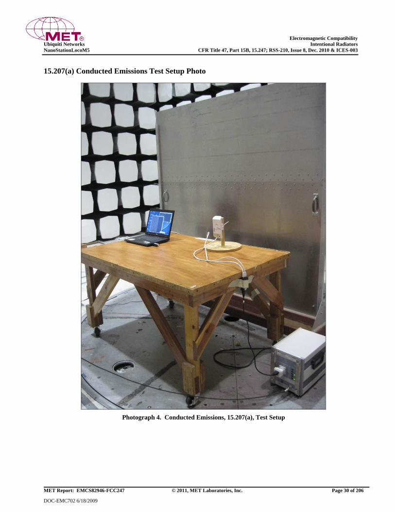
Electromagnetic Compatibility
Ubiquiti Networks Intentional Radiators
NanoStationLocoM5 CFR Title 47, Part 15B, 15.247; RSS-210, Issue 8, Dec. 2010 & ICES-003
MET Report: EMCS82946-FCC247 © 2011, MET Laboratories, Inc. Page 30 of 206
DOC-EMC702 6/18/2009
15.207(a) Conducted Emissions Test Setup Photo
Photograph 4. Conducted Emissions, 15.207(a), Test Setup
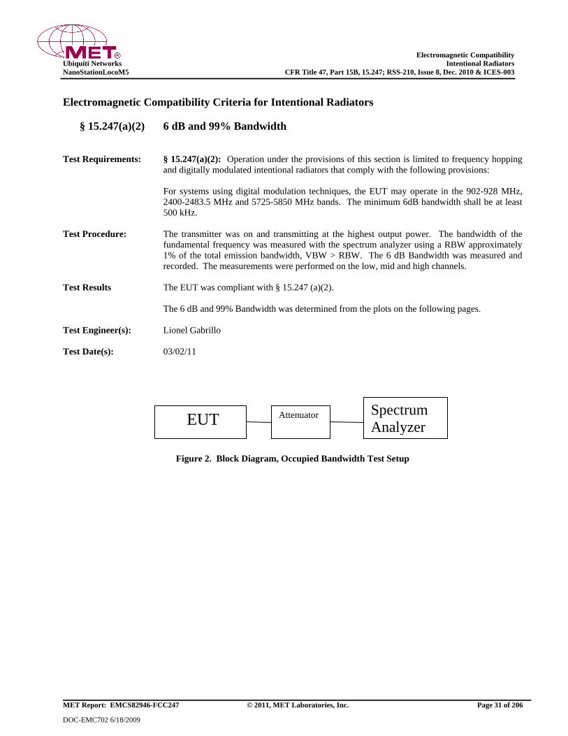
Electromagnetic Compatibility
Ubiquiti Networks Intentional Radiators
NanoStationLocoM5 CFR Title 47, Part 15B, 15.247; RSS-210, Issue 8, Dec. 2010 & ICES-003
MET Report: EMCS82946-FCC247 © 2011, MET Laboratories, Inc. Page 31 of 206
DOC-EMC702 6/18/2009
Electromagnetic Compatibility Criteria for Intentional Radiators
§ 15.247(a)(2) 6 dB and 99% Bandwidth
Test Requirements: § 15.247(a)(2): Operation under the provisions of this section is limited to frequency hopping
and digitally modulated intentional radiators that comply with the following provisions:
For systems using digital modulation techniques, the EUT may operate in the 902-928 MHz,
2400-2483.5 MHz and 5725-5850 MHz bands. The minimum 6dB bandwidth shall be at least
500 kHz.
Test Procedure: The transmitter was on and transmitting at the highest output power. The bandwidth of the
fundamental frequency was measured with the spectrum analyzer using a RBW approximately
1% of the total emission bandwidth, VBW > RBW. The 6 dB Bandwidth was measured and
recorded. The measurements were performed on the low, mid and high channels.
Test Results The EUT was compliant with § 15.247 (a)(2).
The 6 dB and 99% Bandwidth was determined from the plots on the following pages.
Test Engineer(s): Lionel Gabrillo
Test Date(s): 03/02/11
Figure 2. Block Diagram, Occupied Bandwidth Test Setup
EUT Attenuator Spectrum
Analyzer
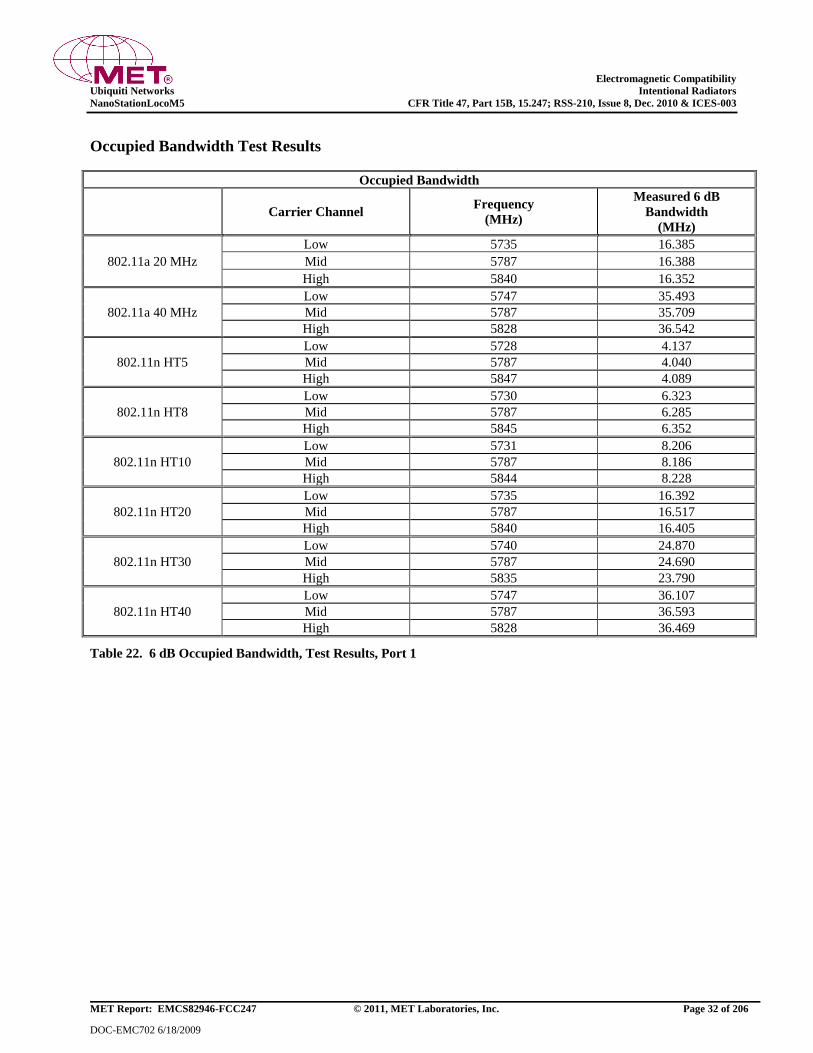
Electromagnetic Compatibility
Ubiquiti Networks Intentional Radiators
NanoStationLocoM5 CFR Title 47, Part 15B, 15.247; RSS-210, Issue 8, Dec. 2010 & ICES-003
MET Report: EMCS82946-FCC247 © 2011, MET Laboratories, Inc. Page 32 of 206
DOC-EMC702 6/18/2009
Occupied Bandwidth Test Results
Occupied Bandwidth
Carrier Channel Frequency
(MHz)
Measured 6 dB
Bandwidth
(MHz)
802.11a 20 MHz
Low 5735 16.385
Mid 5787 16.388
High 5840 16.352
802.11a 40 MHz
Low 5747 35.493
Mid 5787 35.709
High 5828 36.542
802.11n HT5
Low 5728 4.137
Mid 5787 4.040
High 5847 4.089
802.11n HT8
Low 5730 6.323
Mid 5787 6.285
High 5845 6.352
802.11n HT10
Low 5731 8.206
Mid 5787 8.186
High 5844 8.228
802.11n HT20
Low 5735 16.392
Mid 5787 16.517
High 5840 16.405
802.11n HT30
Low 5740 24.870
Mid 5787 24.690
High 5835 23.790
802.11n HT40
Low 5747 36.107
Mid 5787 36.593
High 5828 36.469
Table 22. 6 dB Occupied Bandwidth, Test Results, Port 1
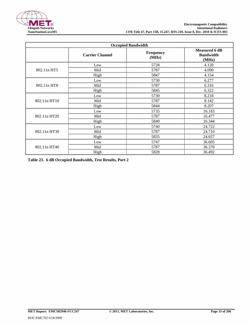
Electromagnetic Compatibility
Ubiquiti Networks Intentional Radiators
NanoStationLocoM5 CFR Title 47, Part 15B, 15.247; RSS-210, Issue 8, Dec. 2010 & ICES-003
MET Report: EMCS82946-FCC247 © 2011, MET Laboratories, Inc. Page 33 of 206
DOC-EMC702 6/18/2009
Occupied Bandwidth
Carrier Channel Frequency
(MHz)
Measured 6 dB
Bandwidth
(MHz)
802.11n HT5
Low 5728 4.120
Mid 5787 4.090
High 5847 4.154
802.11n HT8
Low 5730 6.277
Mid 5787 6.316
High 5845 6.322
802.11n HT10
Low 5730 8.218
Mid 5787 8.142
High 5844 8.207
802.11n HT20
Low 5735 16.183
Mid 5787 16.477
High 5840 16.344
802.11n HT30
Low 5740 24.722
Mid 5787 24.710
High 5835 24.657
802.11n HT40
Low 5747 36.605
Mid 5787 36.378
High 5828 36.492
Table 23. 6 dB Occupied Bandwidth, Test Results, Port 2

Electromagnetic Compatibility
Ubiquiti Networks Intentional Radiators
NanoStationLocoM5 CFR Title 47, Part 15B, 15.247; RSS-210, Issue 8, Dec. 2010 & ICES-003
MET Report: EMCS82946-FCC247 © 2011, MET Laboratories, Inc. Page 34 of 206
DOC-EMC702 6/18/2009
Occupied Bandwidth
Carrier Channel Frequency
(MHz)
Measured 99%
Bandwidth
(MHz)
802.11a 20 MHz
Low 5735 20.6792
Mid 5787 19.2423
High 5840 18.3914
802.11a 40 MHz
Low 5747 36.9601
Mid 5787 37.2787
High 5828 37.1376
802.11n HT5
Low 5728 4.2213
Mid 5787 4.2816
High 5847 4.1833
802.11n HT8
Low 5730 6.7229
Mid 5787 6.7830
High 5845 6.6716
802.11n HT10
Low 5731 8.6339
Mid 5787 8.5151
High 5844 8.5915
802.11n HT20
Low 5735 16.6898
Mid 5787 16.6920
High 5840 16.5332
802.11n HT30
Low 5740 25.5815
Mid 5787 25.6772
High 5835 25.3398
802.11n HT40
Low 5747 37.0736
Mid 5787 37.0528
High 5828 36.6865
Table 24. 99% Occupied Bandwidth, Test Results, Port 1
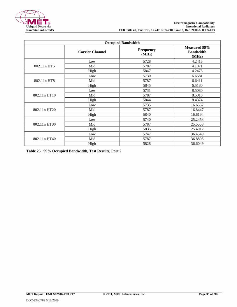
Electromagnetic Compatibility
Ubiquiti Networks Intentional Radiators
NanoStationLocoM5 CFR Title 47, Part 15B, 15.247; RSS-210, Issue 8, Dec. 2010 & ICES-003
MET Report: EMCS82946-FCC247 © 2011, MET Laboratories, Inc. Page 35 of 206
DOC-EMC702 6/18/2009
Occupied Bandwidth
Carrier Channel Frequency
(MHz)
Measured 99%
Bandwidth
(MHz)
802.11n HT5
Low 5728 4.2415
Mid 5787 4.1871
High 5847 4.2475
802.11n HT8
Low 5730 6.6681
Mid 5787 6.6411
High 5845 6.5180
802.11n HT10
Low 5731 8.5080
Mid 5787 8.5018
High 5844 8.4374
802.11n HT20
Low 5735 16.6567
Mid 5787 16.8447
High 5840 16.6194
802.11n HT30
Low 5740 25.2453
Mid 5787 25.5558
High 5835 25.4012
802.11n HT40
Low 5747 36.4549
Mid 5787 36.8895
High 5828 36.6049
Table 25. 99% Occupied Bandwidth, Test Results, Port 2
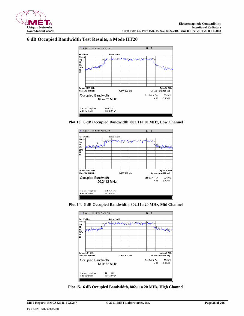
Electromagnetic Compatibility
Ubiquiti Networks Intentional Radiators
NanoStationLocoM5 CFR Title 47, Part 15B, 15.247; RSS-210, Issue 8, Dec. 2010 & ICES-003
MET Report: EMCS82946-FCC247 © 2011, MET Laboratories, Inc. Page 36 of 206
DOC-EMC702 6/18/2009
6 dB Occupied Bandwidth Test Results, a Mode HT20
Plot 13. 6 dB Occupied Bandwidth, 802.11a 20 MHz, Low Channel
Plot 14. 6 dB Occupied Bandwidth, 802.11a 20 MHz, Mid Channel
Plot 15. 6 dB Occupied Bandwidth, 802.11a 20 MHz, High Channel
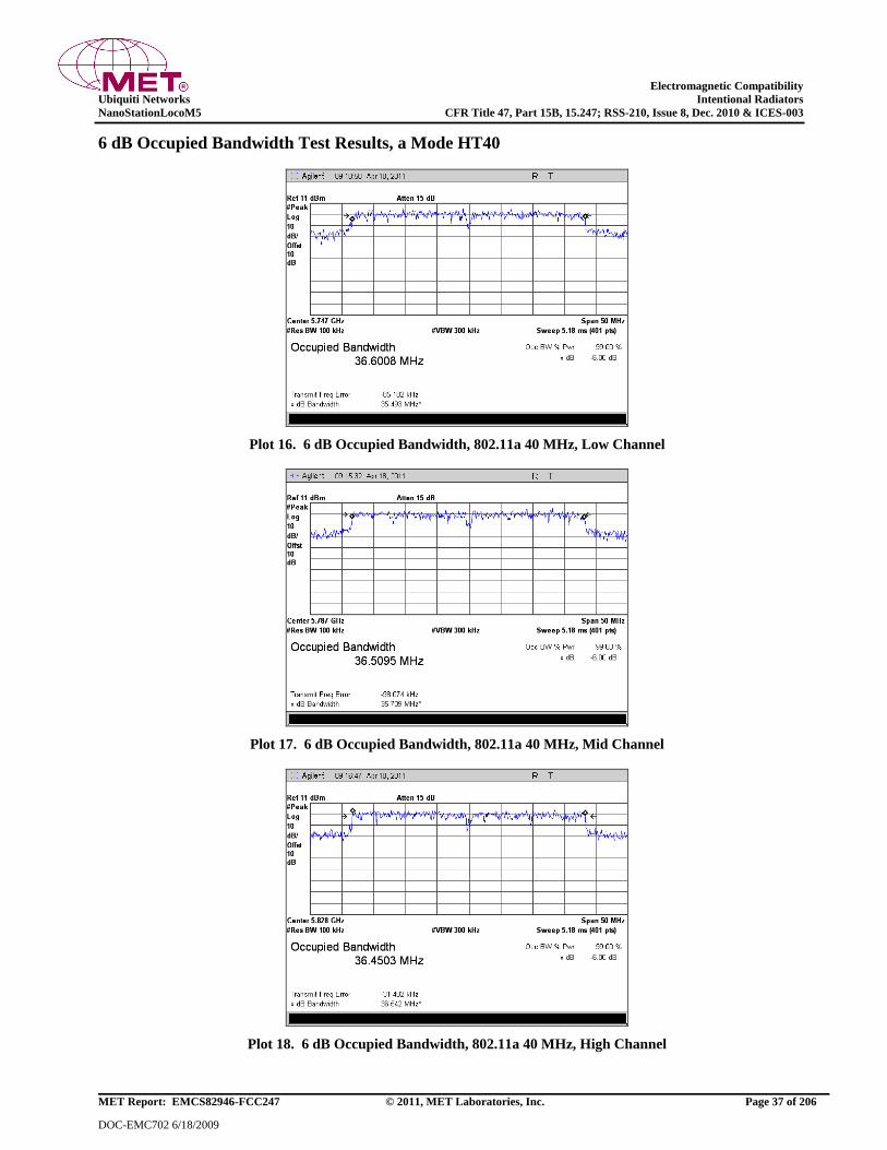
Electromagnetic Compatibility
Ubiquiti Networks Intentional Radiators
NanoStationLocoM5 CFR Title 47, Part 15B, 15.247; RSS-210, Issue 8, Dec. 2010 & ICES-003
MET Report: EMCS82946-FCC247 © 2011, MET Laboratories, Inc. Page 37 of 206
DOC-EMC702 6/18/2009
6 dB Occupied Bandwidth Test Results, a Mode HT40
Plot 16. 6 dB Occupied Bandwidth, 802.11a 40 MHz, Low Channel
Plot 17. 6 dB Occupied Bandwidth, 802.11a 40 MHz, Mid Channel
Plot 18. 6 dB Occupied Bandwidth, 802.11a 40 MHz, High Channel

Electromagnetic Compatibility
Ubiquiti Networks Intentional Radiators
NanoStationLocoM5 CFR Title 47, Part 15B, 15.247; RSS-210, Issue 8, Dec. 2010 & ICES-003
MET Report: EMCS82946-FCC247 © 2011, MET Laboratories, Inc. Page 38 of 206
DOC-EMC702 6/18/2009
6 dB Occupied Bandwidth Test Results, 802.11n HT5, Port 1
Plot 19. 6 dB Occupied Bandwidth, Low Channel, 802.11n HT5, Port 1
Plot 20. 6 dB Occupied Bandwidth, Mid Channel, 802.11n HT5, Port 1
Plot 21. 6 dB Occupied Bandwidth, High Channel, 802.11n HT5, Port 1

Electromagnetic Compatibility
Ubiquiti Networks Intentional Radiators
NanoStationLocoM5 CFR Title 47, Part 15B, 15.247; RSS-210, Issue 8, Dec. 2010 & ICES-003
MET Report: EMCS82946-FCC247 © 2011, MET Laboratories, Inc. Page 39 of 206
DOC-EMC702 6/18/2009
6 dB Occupied Bandwidth Test Results, 802.11n HT5, Port 2
Plot 22. 6 dB Occupied Bandwidth, Low Channel, 802.11n HT5, Port 2
Plot 23. 6 dB Occupied Bandwidth, Mid Channel, 802.11n HT5, Port 2
Plot 24. 6 dB Occupied Bandwidth, High Channel, 802.11n HT5, Port 2

Electromagnetic Compatibility
Ubiquiti Networks Intentional Radiators
NanoStationLocoM5 CFR Title 47, Part 15B, 15.247; RSS-210, Issue 8, Dec. 2010 & ICES-003
MET Report: EMCS82946-FCC247 © 2011, MET Laboratories, Inc. Page 40 of 206
DOC-EMC702 6/18/2009
6 dB Occupied Bandwidth Test Results, 802.11n HT8, Port 1
Plot 25. 6 dB Occupied Bandwidth, Low Channel, 802.11n HT8, Port 1
Plot 26. 6 dB Occupied Bandwidth, Mid Channel, 802.11n HT8, Port 1
Plot 27. 6 dB Occupied Bandwidth, High Channel, 802.11n HT8, Port 1
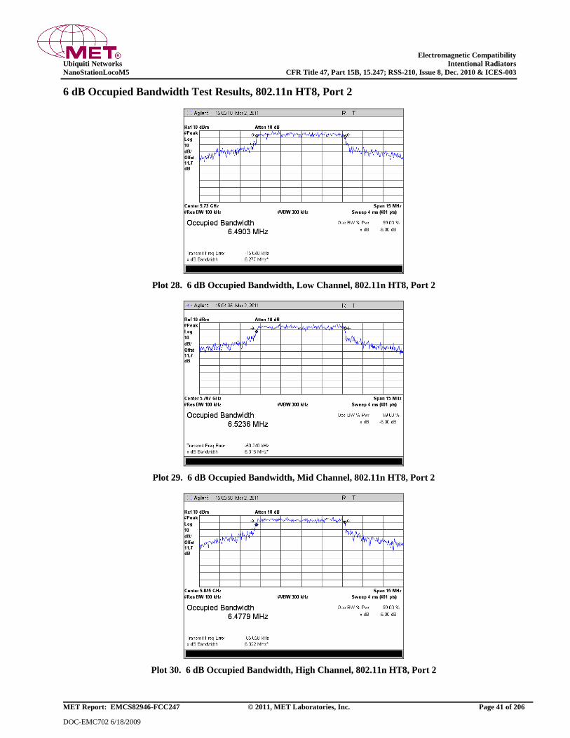
Electromagnetic Compatibility
Ubiquiti Networks Intentional Radiators
NanoStationLocoM5 CFR Title 47, Part 15B, 15.247; RSS-210, Issue 8, Dec. 2010 & ICES-003
MET Report: EMCS82946-FCC247 © 2011, MET Laboratories, Inc. Page 41 of 206
DOC-EMC702 6/18/2009
6 dB Occupied Bandwidth Test Results, 802.11n HT8, Port 2
Plot 28. 6 dB Occupied Bandwidth, Low Channel, 802.11n HT8, Port 2
Plot 29. 6 dB Occupied Bandwidth, Mid Channel, 802.11n HT8, Port 2
Plot 30. 6 dB Occupied Bandwidth, High Channel, 802.11n HT8, Port 2

Electromagnetic Compatibility
Ubiquiti Networks Intentional Radiators
NanoStationLocoM5 CFR Title 47, Part 15B, 15.247; RSS-210, Issue 8, Dec. 2010 & ICES-003
MET Report: EMCS82946-FCC247 © 2011, MET Laboratories, Inc. Page 42 of 206
DOC-EMC702 6/18/2009
6 dB Occupied Bandwidth Test Results, 802.11n HT10, Port 1
Plot 31. 6 dB Occupied Bandwidth, Low Channel, 802.11n HT10, Port 1
Plot 32. 6 dB Occupied Bandwidth, Mid Channel, 802.11n HT10, Port 1
Plot 33. 6 dB Occupied Bandwidth, High Channel, 802.11n HT10, Port 1
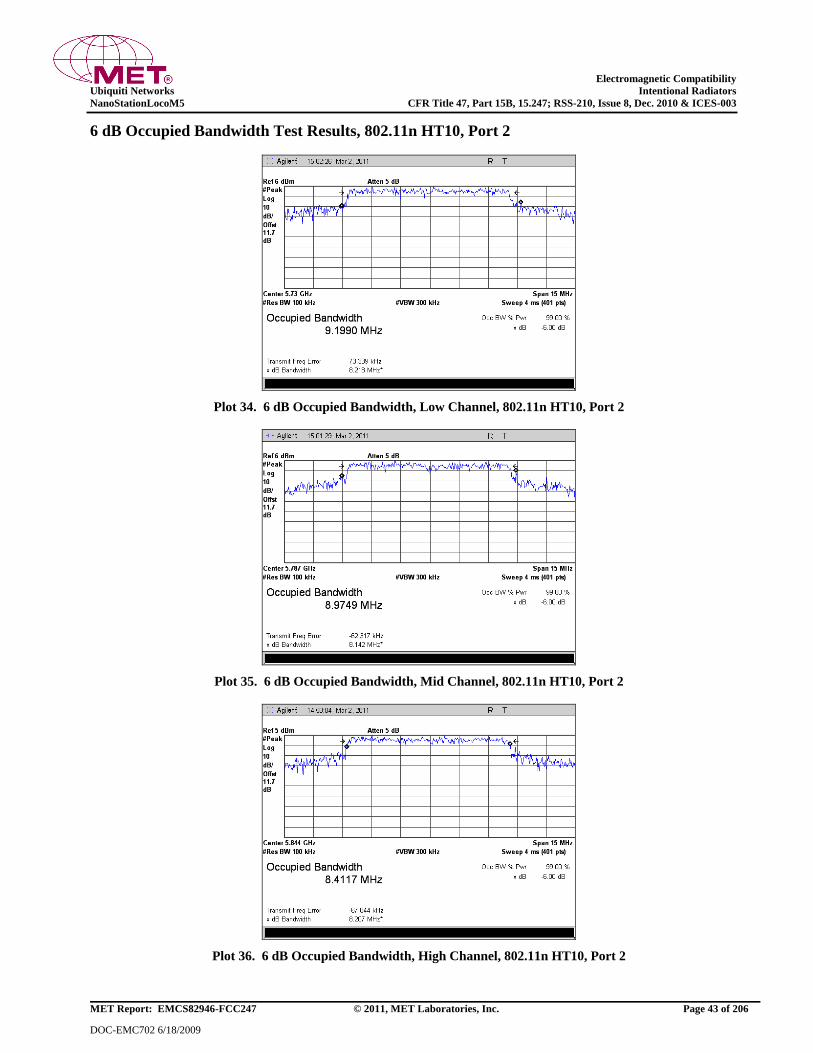
Electromagnetic Compatibility
Ubiquiti Networks Intentional Radiators
NanoStationLocoM5 CFR Title 47, Part 15B, 15.247; RSS-210, Issue 8, Dec. 2010 & ICES-003
MET Report: EMCS82946-FCC247 © 2011, MET Laboratories, Inc. Page 43 of 206
DOC-EMC702 6/18/2009
6 dB Occupied Bandwidth Test Results, 802.11n HT10, Port 2
Plot 34. 6 dB Occupied Bandwidth, Low Channel, 802.11n HT10, Port 2
Plot 35. 6 dB Occupied Bandwidth, Mid Channel, 802.11n HT10, Port 2
Plot 36. 6 dB Occupied Bandwidth, High Channel, 802.11n HT10, Port 2

Electromagnetic Compatibility
Ubiquiti Networks Intentional Radiators
NanoStationLocoM5 CFR Title 47, Part 15B, 15.247; RSS-210, Issue 8, Dec. 2010 & ICES-003
MET Report: EMCS82946-FCC247 © 2011, MET Laboratories, Inc. Page 44 of 206
DOC-EMC702 6/18/2009
6 dB Occupied Bandwidth Test Results, 802.11n HT20, Port 1
Plot 37. 6 dB Occupied Bandwidth, Low Channel, 802.11n HT20, Port 1
Plot 38. 6 dB Occupied Bandwidth, Mid Channel, 802.11n HT20, Port 1
Plot 39. 6 dB Occupied Bandwidth, High Channel, 802.11n HT20, Port 1

Electromagnetic Compatibility
Ubiquiti Networks Intentional Radiators
NanoStationLocoM5 CFR Title 47, Part 15B, 15.247; RSS-210, Issue 8, Dec. 2010 & ICES-003
MET Report: EMCS82946-FCC247 © 2011, MET Laboratories, Inc. Page 45 of 206
DOC-EMC702 6/18/2009
6 dB Occupied Bandwidth Test Results, 802.11n HT20, Port 2
Plot 40. 6 dB Occupied Bandwidth, Low Channel, 802.11n HT20, Port 2
Plot 41. 6 dB Occupied Bandwidth, Mid Channel, 802.11n HT20, Port 2
Plot 42. 6 dB Occupied Bandwidth, High Channel, 802.11n HT20, Port 2
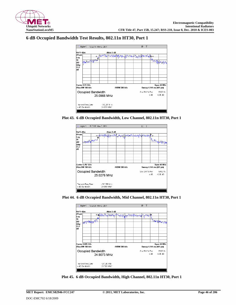
Electromagnetic Compatibility
Ubiquiti Networks Intentional Radiators
NanoStationLocoM5 CFR Title 47, Part 15B, 15.247; RSS-210, Issue 8, Dec. 2010 & ICES-003
MET Report: EMCS82946-FCC247 © 2011, MET Laboratories, Inc. Page 46 of 206
DOC-EMC702 6/18/2009
6 dB Occupied Bandwidth Test Results, 802.11n HT30, Port 1
Plot 43. 6 dB Occupied Bandwidth, Low Channel, 802.11n HT30, Port 1
Plot 44. 6 dB Occupied Bandwidth, Mid Channel, 802.11n HT30, Port 1
Plot 45. 6 dB Occupied Bandwidth, High Channel, 802.11n HT30, Port 1

Electromagnetic Compatibility
Ubiquiti Networks Intentional Radiators
NanoStationLocoM5 CFR Title 47, Part 15B, 15.247; RSS-210, Issue 8, Dec. 2010 & ICES-003
MET Report: EMCS82946-FCC247 © 2011, MET Laboratories, Inc. Page 47 of 206
DOC-EMC702 6/18/2009
6 dB Occupied Bandwidth Test Results, 802.11n HT30, Port 2
Plot 46. 6 dB Occupied Bandwidth, Low Channel, 802.11n HT30, Port 2
Plot 47. 6 dB Occupied Bandwidth, Mid Channel, 802.11n HT30, Port 2
Plot 48. 6 dB Occupied Bandwidth, High Channel, 802.11n HT30, Port 2

Electromagnetic Compatibility
Ubiquiti Networks Intentional Radiators
NanoStationLocoM5 CFR Title 47, Part 15B, 15.247; RSS-210, Issue 8, Dec. 2010 & ICES-003
MET Report: EMCS82946-FCC247 © 2011, MET Laboratories, Inc. Page 48 of 206
DOC-EMC702 6/18/2009
6 dB Occupied Bandwidth Test Results, 802.11n HT40, Port 1
Plot 49. 6 dB Occupied Bandwidth, Low Channel, 802.11n HT40, Port 1
Plot 50. 6 dB Occupied Bandwidth, Mid Channel, 802.11n HT40, Port 1
Plot 51. 6 dB Occupied Bandwidth, High Channel, 802.11n HT40, Port 1
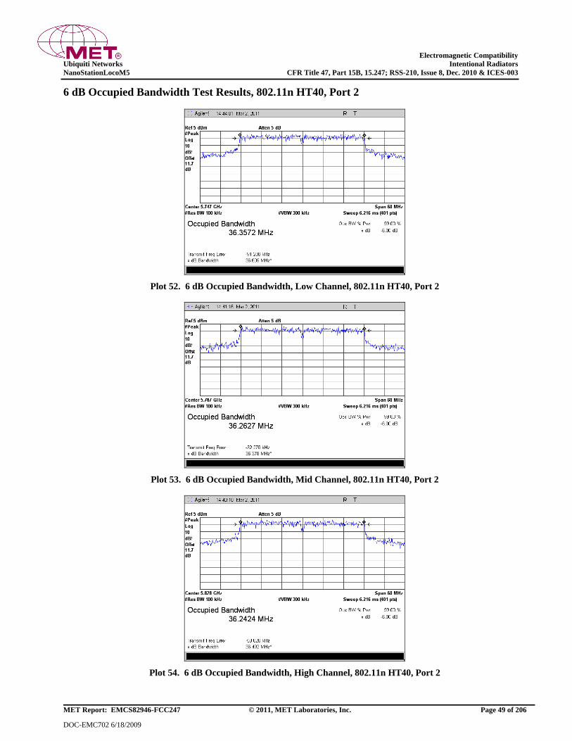
Electromagnetic Compatibility
Ubiquiti Networks Intentional Radiators
NanoStationLocoM5 CFR Title 47, Part 15B, 15.247; RSS-210, Issue 8, Dec. 2010 & ICES-003
MET Report: EMCS82946-FCC247 © 2011, MET Laboratories, Inc. Page 49 of 206
DOC-EMC702 6/18/2009
6 dB Occupied Bandwidth Test Results, 802.11n HT40, Port 2
Plot 52. 6 dB Occupied Bandwidth, Low Channel, 802.11n HT40, Port 2
Plot 53. 6 dB Occupied Bandwidth, Mid Channel, 802.11n HT40, Port 2
Plot 54. 6 dB Occupied Bandwidth, High Channel, 802.11n HT40, Port 2
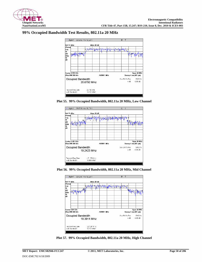
Electromagnetic Compatibility
Ubiquiti Networks Intentional Radiators
NanoStationLocoM5 CFR Title 47, Part 15B, 15.247; RSS-210, Issue 8, Dec. 2010 & ICES-003
MET Report: EMCS82946-FCC247 © 2011, MET Laboratories, Inc. Page 50 of 206
DOC-EMC702 6/18/2009
99% Occupied Bandwidth Test Results, 802.11a 20 MHz
Plot 55. 99% Occupied Bandwidth, 802.11a 20 MHz, Low Channel
Plot 56. 99% Occupied Bandwidth, 802.11a 20 MHz, Mid Channel
Plot 57. 99% Occupied Bandwidth, 802.11a 20 MHz, High Channel
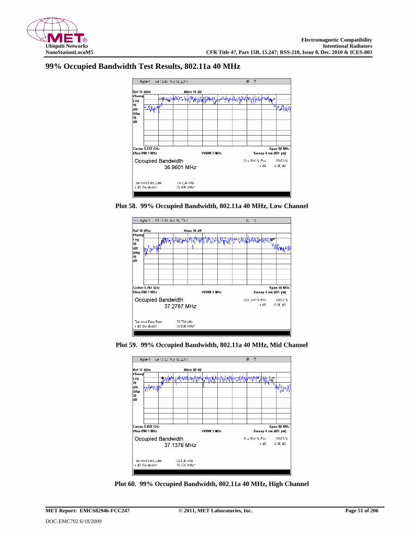
Electromagnetic Compatibility
Ubiquiti Networks Intentional Radiators
NanoStationLocoM5 CFR Title 47, Part 15B, 15.247; RSS-210, Issue 8, Dec. 2010 & ICES-003
MET Report: EMCS82946-FCC247 © 2011, MET Laboratories, Inc. Page 51 of 206
DOC-EMC702 6/18/2009
99% Occupied Bandwidth Test Results, 802.11a 40 MHz
Plot 58. 99% Occupied Bandwidth, 802.11a 40 MHz, Low Channel
Plot 59. 99% Occupied Bandwidth, 802.11a 40 MHz, Mid Channel
Plot 60. 99% Occupied Bandwidth, 802.11a 40 MHz, High Channel

Electromagnetic Compatibility
Ubiquiti Networks Intentional Radiators
NanoStationLocoM5 CFR Title 47, Part 15B, 15.247; RSS-210, Issue 8, Dec. 2010 & ICES-003
MET Report: EMCS82946-FCC247 © 2011, MET Laboratories, Inc. Page 52 of 206
DOC-EMC702 6/18/2009
99% Occupied Bandwidth Test Results, 802.11n HT5, Port 1
Plot 61. 99% Occupied Bandwidth, Low Channel, 802.11n HT5, Port 1
Plot 62. 99% Occupied Bandwidth, Mid Channel, 802.11n HT5, Port 1
Plot 63. 99% Occupied Bandwidth, High Channel, 802.11n HT5, Port 1
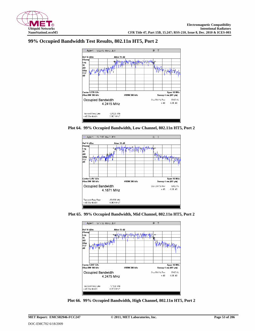
Electromagnetic Compatibility
Ubiquiti Networks Intentional Radiators
NanoStationLocoM5 CFR Title 47, Part 15B, 15.247; RSS-210, Issue 8, Dec. 2010 & ICES-003
MET Report: EMCS82946-FCC247 © 2011, MET Laboratories, Inc. Page 53 of 206
DOC-EMC702 6/18/2009
99% Occupied Bandwidth Test Results, 802.11n HT5, Port 2
Plot 64. 99% Occupied Bandwidth, Low Channel, 802.11n HT5, Port 2
Plot 65. 99% Occupied Bandwidth, Mid Channel, 802.11n HT5, Port 2
Plot 66. 99% Occupied Bandwidth, High Channel, 802.11n HT5, Port 2
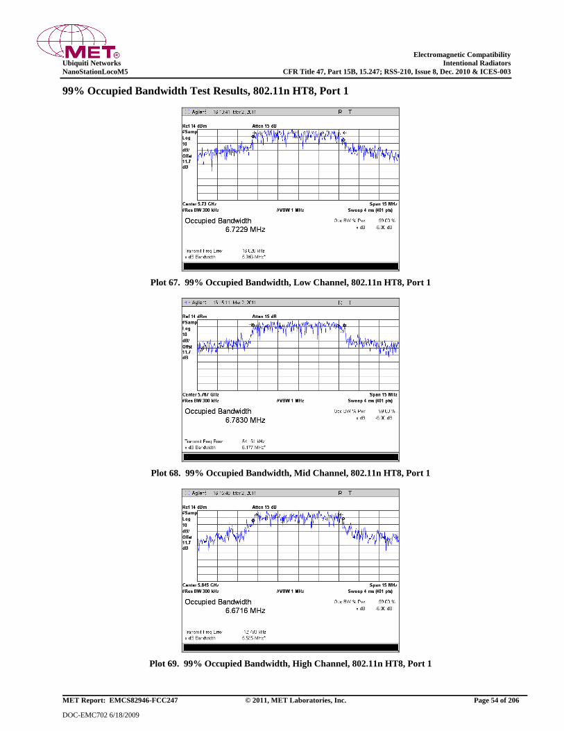
Electromagnetic Compatibility
Ubiquiti Networks Intentional Radiators
NanoStationLocoM5 CFR Title 47, Part 15B, 15.247; RSS-210, Issue 8, Dec. 2010 & ICES-003
MET Report: EMCS82946-FCC247 © 2011, MET Laboratories, Inc. Page 54 of 206
DOC-EMC702 6/18/2009
99% Occupied Bandwidth Test Results, 802.11n HT8, Port 1
Plot 67. 99% Occupied Bandwidth, Low Channel, 802.11n HT8, Port 1
Plot 68. 99% Occupied Bandwidth, Mid Channel, 802.11n HT8, Port 1
Plot 69. 99% Occupied Bandwidth, High Channel, 802.11n HT8, Port 1

Electromagnetic Compatibility
Ubiquiti Networks Intentional Radiators
NanoStationLocoM5 CFR Title 47, Part 15B, 15.247; RSS-210, Issue 8, Dec. 2010 & ICES-003
MET Report: EMCS82946-FCC247 © 2011, MET Laboratories, Inc. Page 55 of 206
DOC-EMC702 6/18/2009
99% Occupied Bandwidth Test Results, 802.11n HT8, Port 2
Plot 70. 99% Occupied Bandwidth, Low Channel, 802.11n HT8, Port 2
Plot 71. 99% Occupied Bandwidth, Mid Channel, 802.11n HT8, Port 2
Plot 72. 99% Occupied Bandwidth, High Channel, 802.11n HT8, Port 2

Electromagnetic Compatibility
Ubiquiti Networks Intentional Radiators
NanoStationLocoM5 CFR Title 47, Part 15B, 15.247; RSS-210, Issue 8, Dec. 2010 & ICES-003
MET Report: EMCS82946-FCC247 © 2011, MET Laboratories, Inc. Page 56 of 206
DOC-EMC702 6/18/2009
99% Occupied Bandwidth Test Results, 802.11n HT10, Port 1
Plot 73. 99% Occupied Bandwidth, Low Channel, 802.11n HT10, Port 1
Plot 74. 99% Occupied Bandwidth, Mid Channel, 802.11n HT10, Port 1
Plot 75. 99% Occupied Bandwidth, High Channel, 802.11n HT10, Port 1
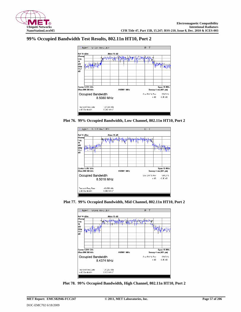
Electromagnetic Compatibility
Ubiquiti Networks Intentional Radiators
NanoStationLocoM5 CFR Title 47, Part 15B, 15.247; RSS-210, Issue 8, Dec. 2010 & ICES-003
MET Report: EMCS82946-FCC247 © 2011, MET Laboratories, Inc. Page 57 of 206
DOC-EMC702 6/18/2009
99% Occupied Bandwidth Test Results, 802.11n HT10, Port 2
Plot 76. 99% Occupied Bandwidth, Low Channel, 802.11n HT10, Port 2
Plot 77. 99% Occupied Bandwidth, Mid Channel, 802.11n HT10, Port 2
Plot 78. 99% Occupied Bandwidth, High Channel, 802.11n HT10, Port 2

Electromagnetic Compatibility
Ubiquiti Networks Intentional Radiators
NanoStationLocoM5 CFR Title 47, Part 15B, 15.247; RSS-210, Issue 8, Dec. 2010 & ICES-003
MET Report: EMCS82946-FCC247 © 2011, MET Laboratories, Inc. Page 58 of 206
DOC-EMC702 6/18/2009
99% Occupied Bandwidth Test Results, 802.11n HT20, Port 1
Plot 79. 99% Occupied Bandwidth, Low Channel, 802.11n HT20, Port 1
Plot 80. 99% Occupied Bandwidth, Mid Channel, 802.11n HT20, Port 1
Plot 81. 99% Occupied Bandwidth, High Channel, 802.11n HT20, Port 1

Electromagnetic Compatibility
Ubiquiti Networks Intentional Radiators
NanoStationLocoM5 CFR Title 47, Part 15B, 15.247; RSS-210, Issue 8, Dec. 2010 & ICES-003
MET Report: EMCS82946-FCC247 © 2011, MET Laboratories, Inc. Page 59 of 206
DOC-EMC702 6/18/2009
99% Occupied Bandwidth Test Results, 802.11n HT20, Port 2
Plot 82. 99% Occupied Bandwidth, Low Channel, 802.11n HT20, Port 2
Plot 83. 99% Occupied Bandwidth, Mid Channel, 802.11n HT20, Port 2
Plot 84. 99% Occupied Bandwidth, High Channel, 802.11n HT20, Port 2
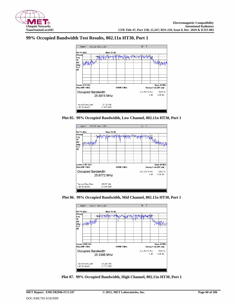
Electromagnetic Compatibility
Ubiquiti Networks Intentional Radiators
NanoStationLocoM5 CFR Title 47, Part 15B, 15.247; RSS-210, Issue 8, Dec. 2010 & ICES-003
MET Report: EMCS82946-FCC247 © 2011, MET Laboratories, Inc. Page 60 of 206
DOC-EMC702 6/18/2009
99% Occupied Bandwidth Test Results, 802.11n HT30, Port 1
Plot 85. 99% Occupied Bandwidth, Low Channel, 802.11n HT30, Port 1
Plot 86. 99% Occupied Bandwidth, Mid Channel, 802.11n HT30, Port 1
Plot 87. 99% Occupied Bandwidth, High Channel, 802.11n HT30, Port 1
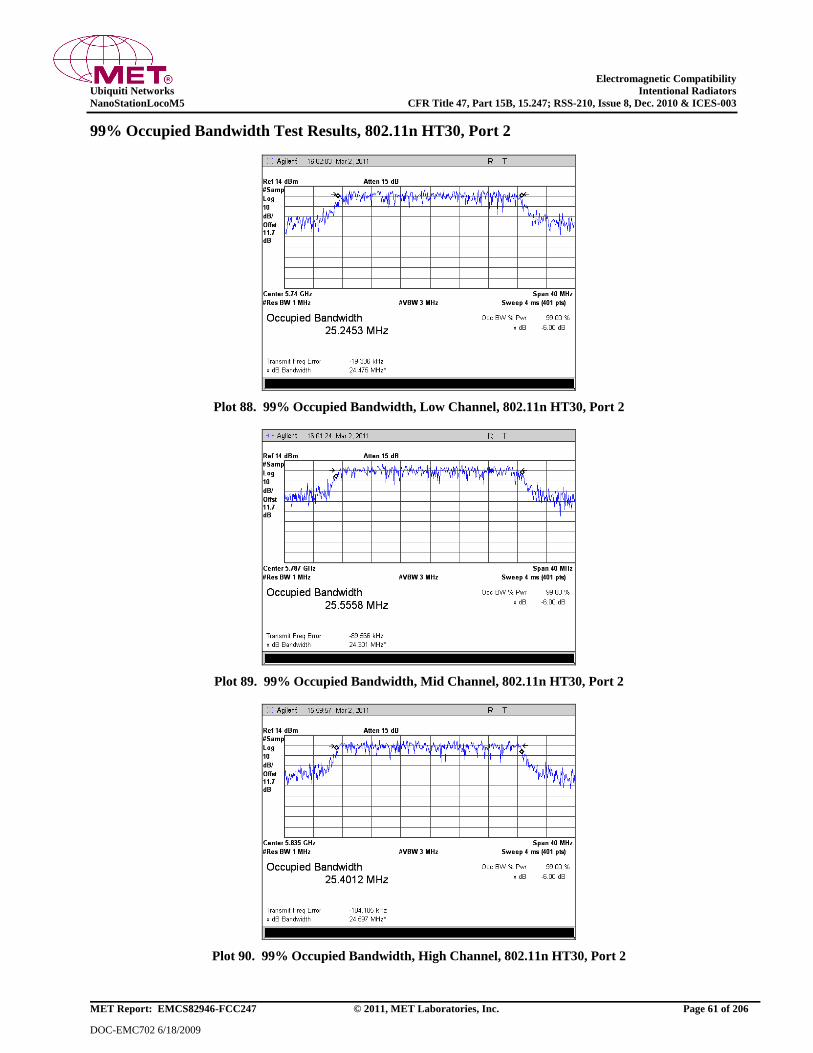
Electromagnetic Compatibility
Ubiquiti Networks Intentional Radiators
NanoStationLocoM5 CFR Title 47, Part 15B, 15.247; RSS-210, Issue 8, Dec. 2010 & ICES-003
MET Report: EMCS82946-FCC247 © 2011, MET Laboratories, Inc. Page 61 of 206
DOC-EMC702 6/18/2009
99% Occupied Bandwidth Test Results, 802.11n HT30, Port 2
Plot 88. 99% Occupied Bandwidth, Low Channel, 802.11n HT30, Port 2
Plot 89. 99% Occupied Bandwidth, Mid Channel, 802.11n HT30, Port 2
Plot 90. 99% Occupied Bandwidth, High Channel, 802.11n HT30, Port 2

Electromagnetic Compatibility
Ubiquiti Networks Intentional Radiators
NanoStationLocoM5 CFR Title 47, Part 15B, 15.247; RSS-210, Issue 8, Dec. 2010 & ICES-003
MET Report: EMCS82946-FCC247 © 2011, MET Laboratories, Inc. Page 62 of 206
DOC-EMC702 6/18/2009
99% Occupied Bandwidth Test Results, 802.11n HT40, Port 1
Plot 91. 99% Occupied Bandwidth, Low Channel, 802.11n HT40, Port 1
Plot 92. 99% Occupied Bandwidth, Mid Channel, 802.11n HT40, Port 1
Plot 93. 99% Occupied Bandwidth, High Channel, 802.11n HT40, Port 1
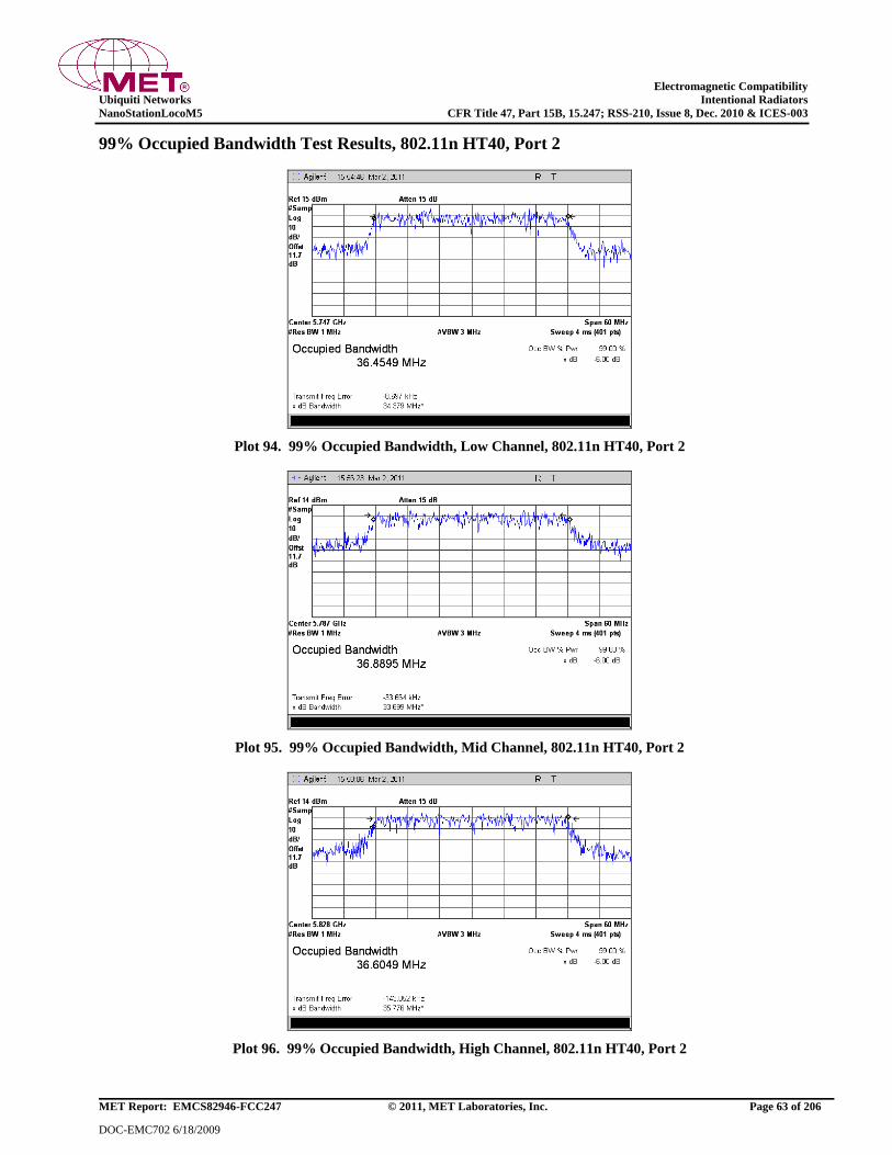
Electromagnetic Compatibility
Ubiquiti Networks Intentional Radiators
NanoStationLocoM5 CFR Title 47, Part 15B, 15.247; RSS-210, Issue 8, Dec. 2010 & ICES-003
MET Report: EMCS82946-FCC247 © 2011, MET Laboratories, Inc. Page 63 of 206
DOC-EMC702 6/18/2009
99% Occupied Bandwidth Test Results, 802.11n HT40, Port 2
Plot 94. 99% Occupied Bandwidth, Low Channel, 802.11n HT40, Port 2
Plot 95. 99% Occupied Bandwidth, Mid Channel, 802.11n HT40, Port 2
Plot 96. 99% Occupied Bandwidth, High Channel, 802.11n HT40, Port 2
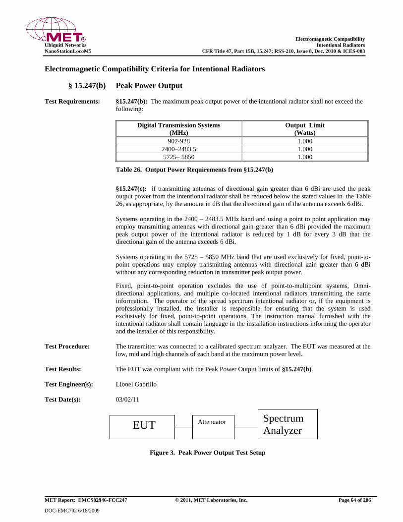
Electromagnetic Compatibility
Ubiquiti Networks Intentional Radiators
NanoStationLocoM5 CFR Title 47, Part 15B, 15.247; RSS-210, Issue 8, Dec. 2010 & ICES-003
MET Report: EMCS82946-FCC247 © 2011, MET Laboratories, Inc. Page 64 of 206
DOC-EMC702 6/18/2009
Electromagnetic Compatibility Criteria for Intentional Radiators
§ 15.247(b) Peak Power Output
Test Requirements: §15.247(b): The maximum peak output power of the intentional radiator shall not exceed the
following:
Digital Transmission Systems
(MHz)
Output Limit
(Watts)
902-928 1.000
2400–2483.5 1.000
5725– 5850 1.000
Table 26. Output Power Requirements from §15.247(b)
§15.247(c): if transmitting antennas of directional gain greater than 6 dBi are used the peak
output power from the intentional radiator shall be reduced below the stated values in the Table
26, as appropriate, by the amount in dB that the directional gain of the antenna exceeds 6 dBi.
Systems operating in the 2400 – 2483.5 MHz band and using a point to point application may
employ transmitting antennas with directional gain greater than 6 dBi provided the maximum
peak output power of the intentional radiator is reduced by 1 dB for every 3 dB that the
directional gain of the antenna exceeds 6 dBi.
Systems operating in the 5725 – 5850 MHz band that are used exclusively for fixed, point-to-
point operations may employ transmitting antennas with directional gain greater than 6 dBi
without any corresponding reduction in transmitter peak output power.
Fixed, point-to-point operation excludes the use of point-to-multipoint systems, Omni-
directional applications, and multiple co-located intentional radiators transmitting the same
information. The operator of the spread spectrum intentional radiator or, if the equipment is
professionally installed, the installer is responsible for ensuring that the system is used
exclusively for fixed, point-to-point operations. The instruction manual furnished with the
intentional radiator shall contain language in the installation instructions informing the operator
and the installer of this responsibility.
Test Procedure: The transmitter was connected to a calibrated spectrum analyzer. The EUT was measured at the
low, mid and high channels of each band at the maximum power level.
Test Results: The EUT was compliant with the Peak Power Output limits of §15.247(b).
Test Engineer(s): Lionel Gabrillo
Test Date(s): 03/02/11
Figure 3. Peak Power Output Test Setup
EUT Attenuator Spectrum
Analyzer
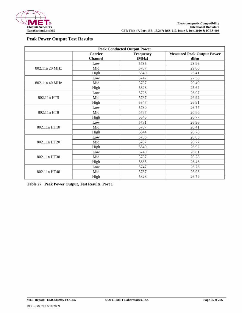
Electromagnetic Compatibility
Ubiquiti Networks Intentional Radiators
NanoStationLocoM5 CFR Title 47, Part 15B, 15.247; RSS-210, Issue 8, Dec. 2010 & ICES-003
MET Report: EMCS82946-FCC247 © 2011, MET Laboratories, Inc. Page 65 of 206
DOC-EMC702 6/18/2009
Peak Power Output Test Results
Peak Conducted Output Power
Carrier
Channel
Frequency
(MHz)
Measured Peak Output Power
dBm
802.11a 20 MHz
Low 5735 23.96
Mid 5787 29.80
High 5840 25.41
802.11a 40 MHz
Low 5747 27.38
Mid 5787 29.49
High 5828 25.62
802.11n HT5
Low 5728 26.97
Mid 5787 26.92
High 5847 26.91
802.11n HT8
Low 5730 26.77
Mid 5787 26.86
High 5845 26.77
802.11n HT10
Low 5731 26.96
Mid 5787 26.41
High 5844 26.78
802.11n HT20
Low 5735 26.85
Mid 5787 26.77
High 5840 26.92
802.11n HT30
Low 5740 26.81
Mid 5787 26.28
High 5835 26.46
802.11n HT40
Low 5747 26.73
Mid 5787 26.93
High 5828 26.79
Table 27. Peak Power Output, Test Results, Port 1
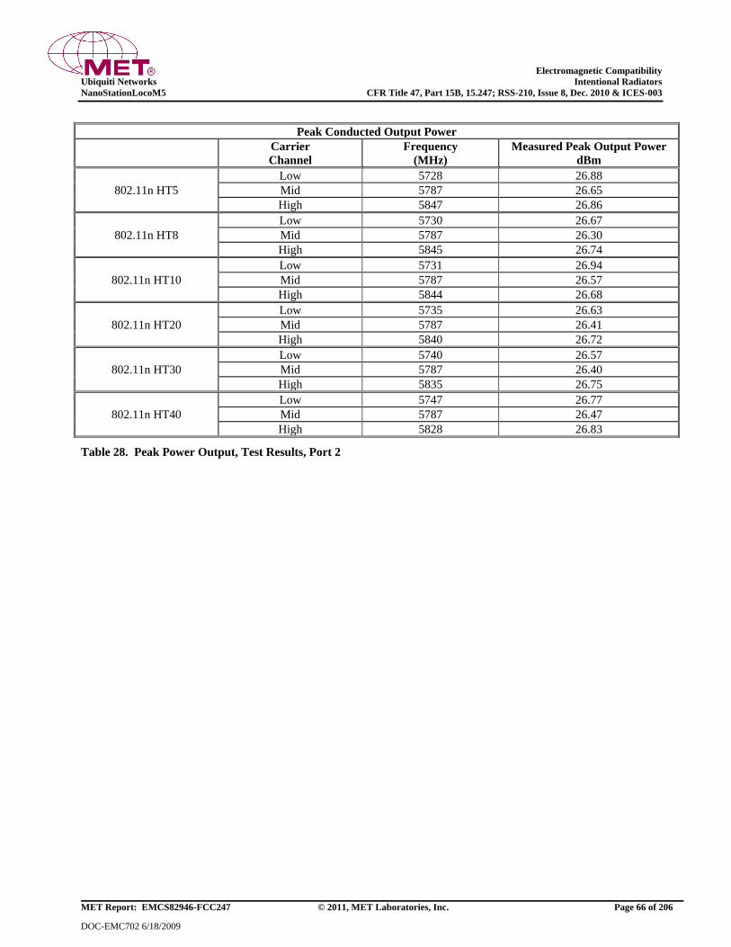
Electromagnetic Compatibility
Ubiquiti Networks Intentional Radiators
NanoStationLocoM5 CFR Title 47, Part 15B, 15.247; RSS-210, Issue 8, Dec. 2010 & ICES-003
MET Report: EMCS82946-FCC247 © 2011, MET Laboratories, Inc. Page 66 of 206
DOC-EMC702 6/18/2009
Peak Conducted Output Power
Carrier
Channel
Frequency
(MHz)
Measured Peak Output Power
dBm
802.11n HT5
Low 5728 26.88
Mid 5787 26.65
High 5847 26.86
802.11n HT8
Low 5730 26.67
Mid 5787 26.30
High 5845 26.74
802.11n HT10
Low 5731 26.94
Mid 5787 26.57
High 5844 26.68
802.11n HT20
Low 5735 26.63
Mid 5787 26.41
High 5840 26.72
802.11n HT30
Low 5740 26.57
Mid 5787 26.40
High 5835 26.75
802.11n HT40
Low 5747 26.77
Mid 5787 26.47
High 5828 26.83
Table 28. Peak Power Output, Test Results, Port 2
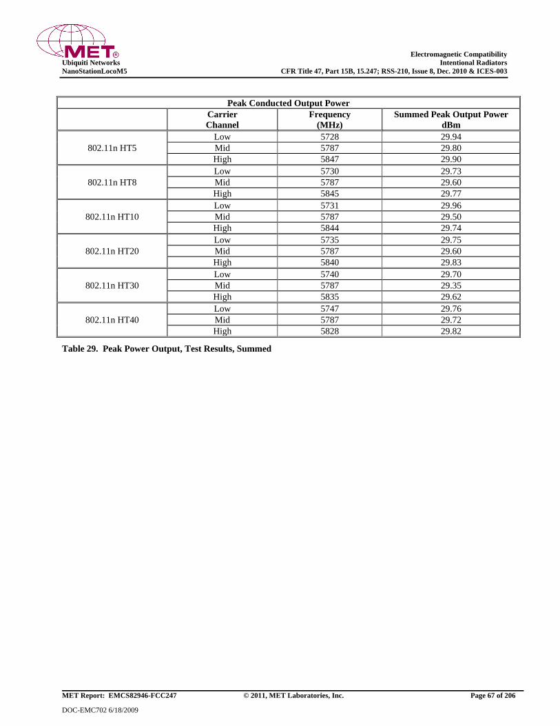
Electromagnetic Compatibility
Ubiquiti Networks Intentional Radiators
NanoStationLocoM5 CFR Title 47, Part 15B, 15.247; RSS-210, Issue 8, Dec. 2010 & ICES-003
MET Report: EMCS82946-FCC247 © 2011, MET Laboratories, Inc. Page 67 of 206
DOC-EMC702 6/18/2009
Peak Conducted Output Power
Carrier
Channel
Frequency
(MHz)
Summed Peak Output Power
dBm
802.11n HT5
Low 5728 29.94
Mid 5787 29.80
High 5847 29.90
802.11n HT8
Low 5730 29.73
Mid 5787 29.60
High 5845 29.77
802.11n HT10
Low 5731 29.96
Mid 5787 29.50
High 5844 29.74
802.11n HT20
Low 5735 29.75
Mid 5787 29.60
High 5840 29.83
802.11n HT30
Low 5740 29.70
Mid 5787 29.35
High 5835 29.62
802.11n HT40
Low 5747 29.76
Mid 5787 29.72
High 5828 29.82
Table 29. Peak Power Output, Test Results, Summed
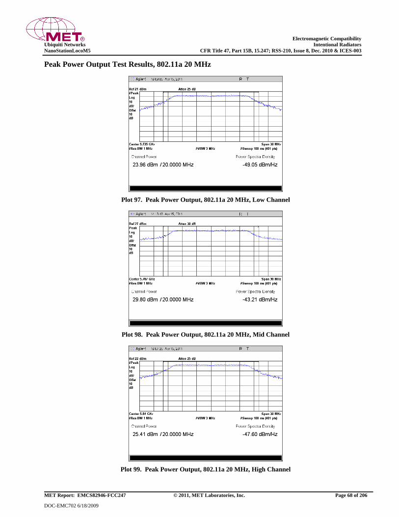
Electromagnetic Compatibility
Ubiquiti Networks Intentional Radiators
NanoStationLocoM5 CFR Title 47, Part 15B, 15.247; RSS-210, Issue 8, Dec. 2010 & ICES-003
MET Report: EMCS82946-FCC247 © 2011, MET Laboratories, Inc. Page 68 of 206
DOC-EMC702 6/18/2009
Peak Power Output Test Results, 802.11a 20 MHz
Plot 97. Peak Power Output, 802.11a 20 MHz, Low Channel
Plot 98. Peak Power Output, 802.11a 20 MHz, Mid Channel
Plot 99. Peak Power Output, 802.11a 20 MHz, High Channel
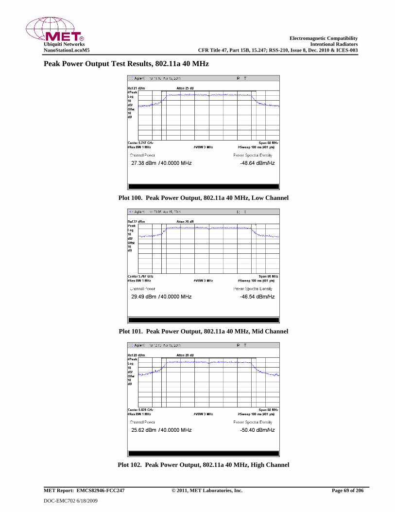
Electromagnetic Compatibility
Ubiquiti Networks Intentional Radiators
NanoStationLocoM5 CFR Title 47, Part 15B, 15.247; RSS-210, Issue 8, Dec. 2010 & ICES-003
MET Report: EMCS82946-FCC247 © 2011, MET Laboratories, Inc. Page 69 of 206
DOC-EMC702 6/18/2009
Peak Power Output Test Results, 802.11a 40 MHz
Plot 100. Peak Power Output, 802.11a 40 MHz, Low Channel
Plot 101. Peak Power Output, 802.11a 40 MHz, Mid Channel
Plot 102. Peak Power Output, 802.11a 40 MHz, High Channel
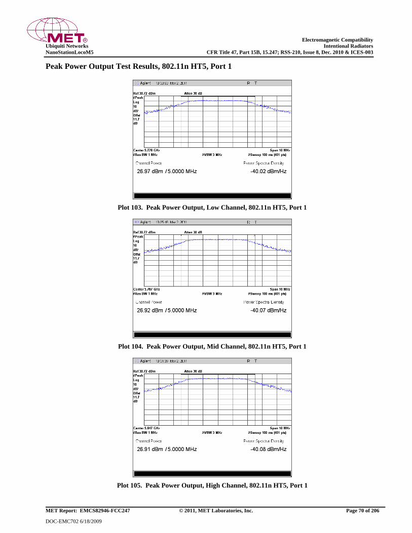
Electromagnetic Compatibility
Ubiquiti Networks Intentional Radiators
NanoStationLocoM5 CFR Title 47, Part 15B, 15.247; RSS-210, Issue 8, Dec. 2010 & ICES-003
MET Report: EMCS82946-FCC247 © 2011, MET Laboratories, Inc. Page 70 of 206
DOC-EMC702 6/18/2009
Peak Power Output Test Results, 802.11n HT5, Port 1
Plot 103. Peak Power Output, Low Channel, 802.11n HT5, Port 1
Plot 104. Peak Power Output, Mid Channel, 802.11n HT5, Port 1
Plot 105. Peak Power Output, High Channel, 802.11n HT5, Port 1
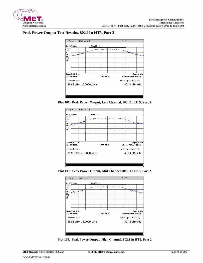
Electromagnetic Compatibility
Ubiquiti Networks Intentional Radiators
NanoStationLocoM5 CFR Title 47, Part 15B, 15.247; RSS-210, Issue 8, Dec. 2010 & ICES-003
MET Report: EMCS82946-FCC247 © 2011, MET Laboratories, Inc. Page 71 of 206
DOC-EMC702 6/18/2009
Peak Power Output Test Results, 802.11n HT5, Port 2
Plot 106. Peak Power Output, Low Channel, 802.11n HT5, Port 2
Plot 107. Peak Power Output, Mid Channel, 802.11n HT5, Port 2
Plot 108. Peak Power Output, High Channel, 802.11n HT5, Port 2
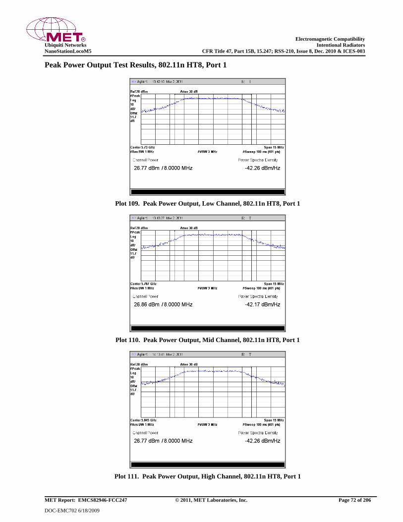
Electromagnetic Compatibility
Ubiquiti Networks Intentional Radiators
NanoStationLocoM5 CFR Title 47, Part 15B, 15.247; RSS-210, Issue 8, Dec. 2010 & ICES-003
MET Report: EMCS82946-FCC247 © 2011, MET Laboratories, Inc. Page 72 of 206
DOC-EMC702 6/18/2009
Peak Power Output Test Results, 802.11n HT8, Port 1
Plot 109. Peak Power Output, Low Channel, 802.11n HT8, Port 1
Plot 110. Peak Power Output, Mid Channel, 802.11n HT8, Port 1
Plot 111. Peak Power Output, High Channel, 802.11n HT8, Port 1
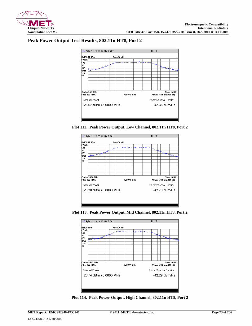
Electromagnetic Compatibility
Ubiquiti Networks Intentional Radiators
NanoStationLocoM5 CFR Title 47, Part 15B, 15.247; RSS-210, Issue 8, Dec. 2010 & ICES-003
MET Report: EMCS82946-FCC247 © 2011, MET Laboratories, Inc. Page 73 of 206
DOC-EMC702 6/18/2009
Peak Power Output Test Results, 802.11n HT8, Port 2
Plot 112. Peak Power Output, Low Channel, 802.11n HT8, Port 2
Plot 113. Peak Power Output, Mid Channel, 802.11n HT8, Port 2
Plot 114. Peak Power Output, High Channel, 802.11n HT8, Port 2
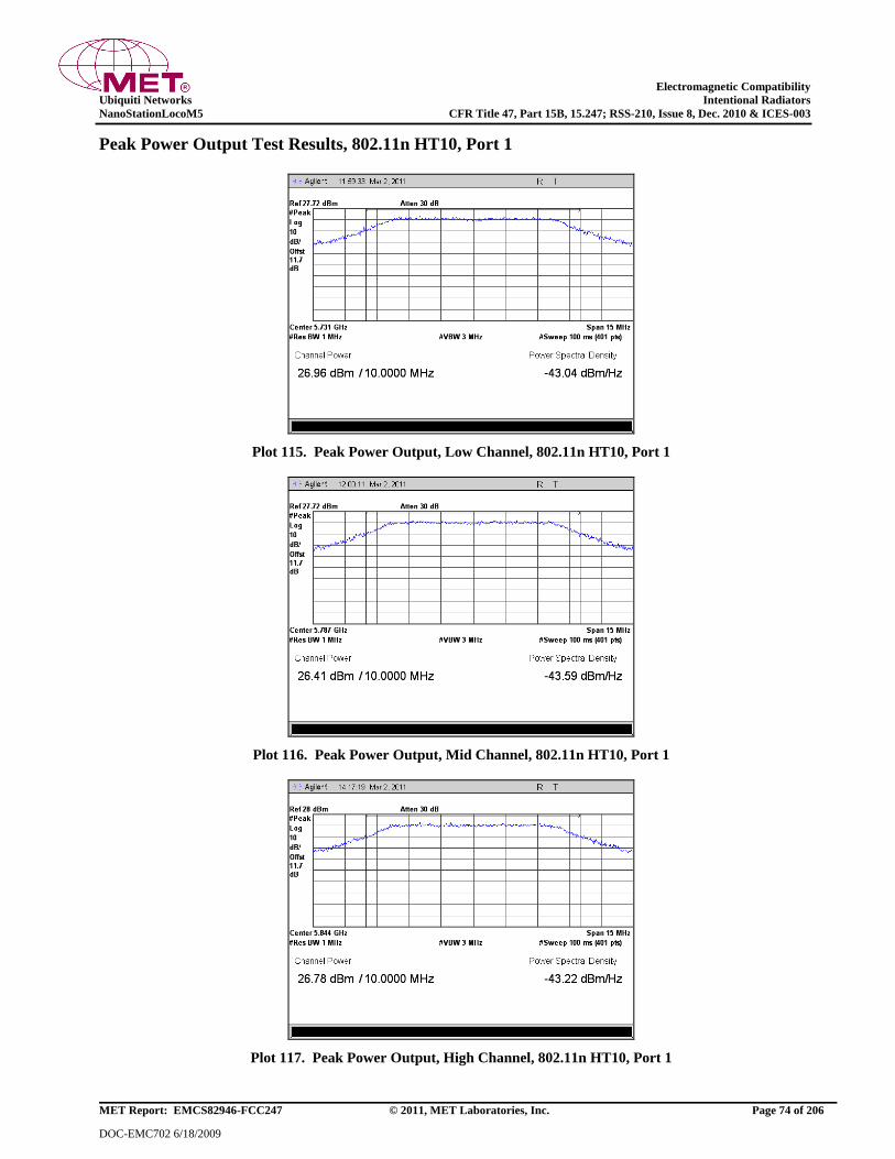
Electromagnetic Compatibility
Ubiquiti Networks Intentional Radiators
NanoStationLocoM5 CFR Title 47, Part 15B, 15.247; RSS-210, Issue 8, Dec. 2010 & ICES-003
MET Report: EMCS82946-FCC247 © 2011, MET Laboratories, Inc. Page 74 of 206
DOC-EMC702 6/18/2009
Peak Power Output Test Results, 802.11n HT10, Port 1
Plot 115. Peak Power Output, Low Channel, 802.11n HT10, Port 1
Plot 116. Peak Power Output, Mid Channel, 802.11n HT10, Port 1
Plot 117. Peak Power Output, High Channel, 802.11n HT10, Port 1

Electromagnetic Compatibility
Ubiquiti Networks Intentional Radiators
NanoStationLocoM5 CFR Title 47, Part 15B, 15.247; RSS-210, Issue 8, Dec. 2010 & ICES-003
MET Report: EMCS82946-FCC247 © 2011, MET Laboratories, Inc. Page 75 of 206
DOC-EMC702 6/18/2009
Peak Power Output Test Results, 802.11n HT10, Port 2
Plot 118. Peak Power Output, Low Channel, 802.11n HT10, Port 2
Plot 119. Peak Power Output, Mid Channel, 802.11n HT10, Port 2
Plot 120. Peak Power Output, High Channel, 802.11n HT10, Port 2
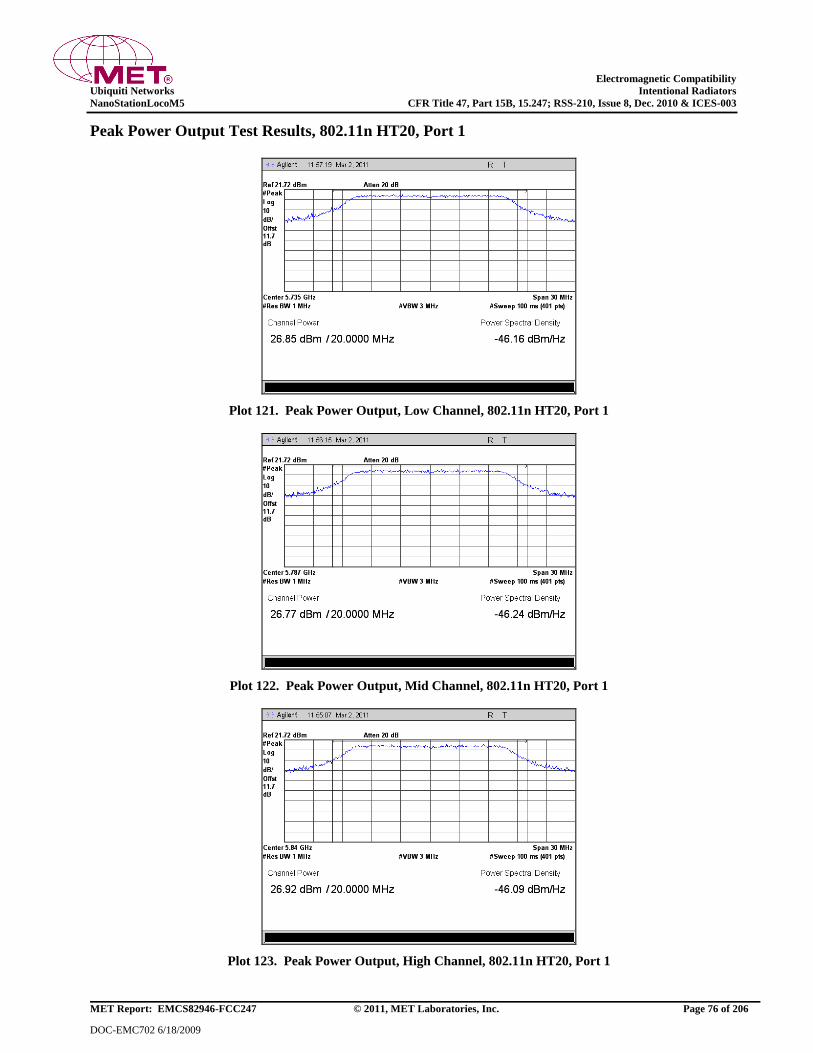
Electromagnetic Compatibility
Ubiquiti Networks Intentional Radiators
NanoStationLocoM5 CFR Title 47, Part 15B, 15.247; RSS-210, Issue 8, Dec. 2010 & ICES-003
MET Report: EMCS82946-FCC247 © 2011, MET Laboratories, Inc. Page 76 of 206
DOC-EMC702 6/18/2009
Peak Power Output Test Results, 802.11n HT20, Port 1
Plot 121. Peak Power Output, Low Channel, 802.11n HT20, Port 1
Plot 122. Peak Power Output, Mid Channel, 802.11n HT20, Port 1
Plot 123. Peak Power Output, High Channel, 802.11n HT20, Port 1

Electromagnetic Compatibility
Ubiquiti Networks Intentional Radiators
NanoStationLocoM5 CFR Title 47, Part 15B, 15.247; RSS-210, Issue 8, Dec. 2010 & ICES-003
MET Report: EMCS82946-FCC247 © 2011, MET Laboratories, Inc. Page 77 of 206
DOC-EMC702 6/18/2009
Peak Power Output Test Results, 802.11n HT20, Port 2
Plot 124. Peak Power Output, Low Channel, 802.11n HT20, Port 2
Plot 125. Peak Power Output, Mid Channel, 802.11n HT20, Port 2
Plot 126. Peak Power Output, High Channel, 802.11n HT20, Port 2

Electromagnetic Compatibility
Ubiquiti Networks Intentional Radiators
NanoStationLocoM5 CFR Title 47, Part 15B, 15.247; RSS-210, Issue 8, Dec. 2010 & ICES-003
MET Report: EMCS82946-FCC247 © 2011, MET Laboratories, Inc. Page 78 of 206
DOC-EMC702 6/18/2009
Peak Power Output Test Results, 802.11n HT30, Port 1
Plot 127. Peak Power Output, Low Channel, 802.11n HT30, Port 1
Plot 128. Peak Power Output, Mid Channel, 802.11n HT30, Port 1
Plot 129. Peak Power Output, High Channel, 802.11n HT30, Port 1

Electromagnetic Compatibility
Ubiquiti Networks Intentional Radiators
NanoStationLocoM5 CFR Title 47, Part 15B, 15.247; RSS-210, Issue 8, Dec. 2010 & ICES-003
MET Report: EMCS82946-FCC247 © 2011, MET Laboratories, Inc. Page 79 of 206
DOC-EMC702 6/18/2009
Peak Power Output Test Results, 802.11n HT30, Port 2
Plot 130. Peak Power Output, Low Channel, 802.11n HT30, Port 2
Plot 131. Peak Power Output, Mid Channel, 802.11n HT30, Port 2
Plot 132. Peak Power Output, High Channel, 802.11n HT30, Port 2
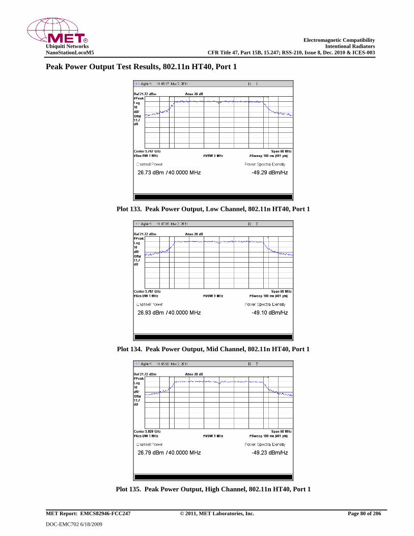
Electromagnetic Compatibility
Ubiquiti Networks Intentional Radiators
NanoStationLocoM5 CFR Title 47, Part 15B, 15.247; RSS-210, Issue 8, Dec. 2010 & ICES-003
MET Report: EMCS82946-FCC247 © 2011, MET Laboratories, Inc. Page 80 of 206
DOC-EMC702 6/18/2009
Peak Power Output Test Results, 802.11n HT40, Port 1
Plot 133. Peak Power Output, Low Channel, 802.11n HT40, Port 1
Plot 134. Peak Power Output, Mid Channel, 802.11n HT40, Port 1
Plot 135. Peak Power Output, High Channel, 802.11n HT40, Port 1
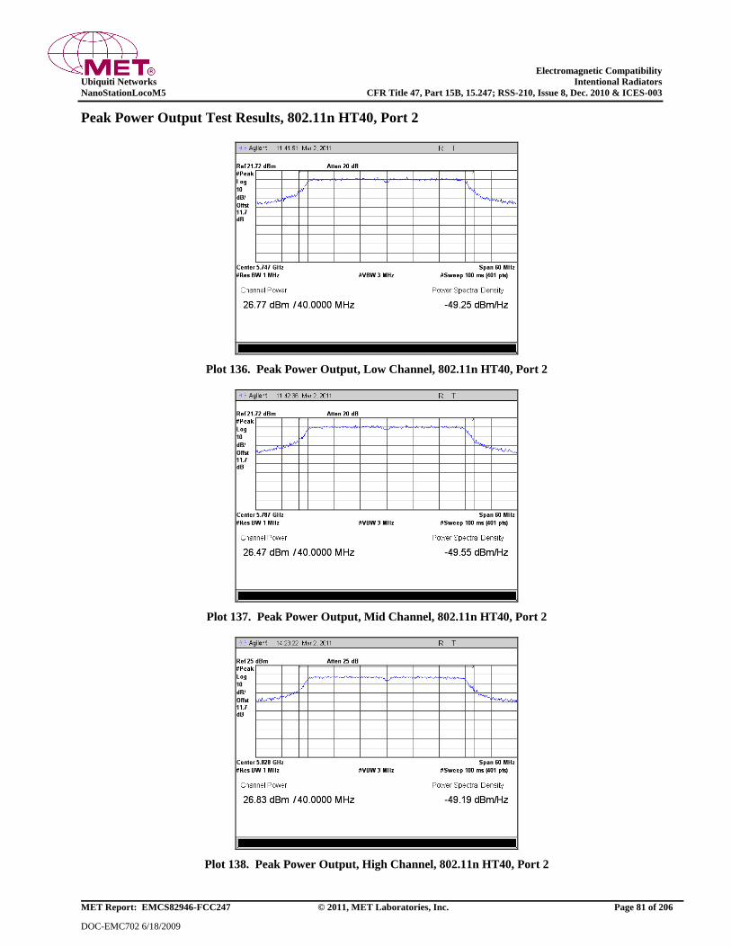
Electromagnetic Compatibility
Ubiquiti Networks Intentional Radiators
NanoStationLocoM5 CFR Title 47, Part 15B, 15.247; RSS-210, Issue 8, Dec. 2010 & ICES-003
MET Report: EMCS82946-FCC247 © 2011, MET Laboratories, Inc. Page 81 of 206
DOC-EMC702 6/18/2009
Peak Power Output Test Results, 802.11n HT40, Port 2
Plot 136. Peak Power Output, Low Channel, 802.11n HT40, Port 2
Plot 137. Peak Power Output, Mid Channel, 802.11n HT40, Port 2
Plot 138. Peak Power Output, High Channel, 802.11n HT40, Port 2
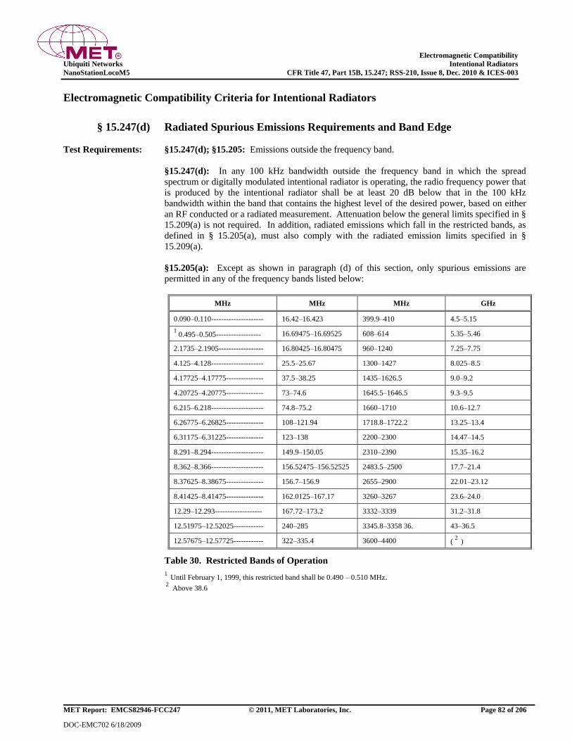
Electromagnetic Compatibility
Ubiquiti Networks Intentional Radiators
NanoStationLocoM5 CFR Title 47, Part 15B, 15.247; RSS-210, Issue 8, Dec. 2010 & ICES-003
MET Report: EMCS82946-FCC247 © 2011, MET Laboratories, Inc. Page 82 of 206
DOC-EMC702 6/18/2009
Electromagnetic Compatibility Criteria for Intentional Radiators
§ 15.247(d) Radiated Spurious Emissions Requirements and Band Edge
Test Requirements: §15.247(d); §15.205: Emissions outside the frequency band.
§15.247(d): In any 100 kHz bandwidth outside the frequency band in which the spread
spectrum or digitally modulated intentional radiator is operating, the radio frequency power that
is produced by the intentional radiator shall be at least 20 dB below that in the 100 kHz
bandwidth within the band that contains the highest level of the desired power, based on either
an RF conducted or a radiated measurement. Attenuation below the general limits specified in §
15.209(a) is not required. In addition, radiated emissions which fall in the restricted bands, as
defined in § 15.205(a), must also comply with the radiated emission limits specified in §
15.209(a).
§15.205(a): Except as shown in paragraph (d) of this section, only spurious emissions are
permitted in any of the frequency bands listed below:
MHz MHz MHz GHz
0.090–0.110--------------------- 16.42–16.423 399.9–410 4.5–5.15
1 0.495–0.505------------------ 16.69475–16.69525 608–614 5.35–5.46
2.1735–2.1905------------------ 16.80425–16.80475 960–1240 7.25–7.75
4.125–4.128--------------------- 25.5–25.67 1300–1427 8.025–8.5
4.17725–4.17775--------------- 37.5–38.25 1435–1626.5 9.0–9.2
4.20725–4.20775--------------- 73–74.6 1645.5–1646.5 9.3–9.5
6.215–6.218--------------------- 74.8–75.2 1660–1710 10.6–12.7
6.26775–6.26825--------------- 108–121.94 1718.8–1722.2 13.25–13.4
6.31175–6.31225--------------- 123–138 2200–2300 14.47–14.5
8.291–8.294--------------------- 149.9–150.05 2310–2390 15.35–16.2
8.362–8.366--------------------- 156.52475–156.52525 2483.5–2500 17.7–21.4
8.37625–8.38675--------------- 156.7–156.9 2655–2900 22.01–23.12
8.41425–8.41475--------------- 162.0125–167.17 3260–3267 23.6–24.0
12.29–12.293------------------- 167.72–173.2 3332–3339 31.2–31.8
12.51975–12.52025------------ 240–285 3345.8–3358 36. 43–36.5
12.57675–12.57725------------ 322–335.4 3600–4400 ( 2
)
Table 30. Restricted Bands of Operation
1 Until February 1, 1999, this restricted band shall be 0.490 – 0.510 MHz.
2 Above 38.6
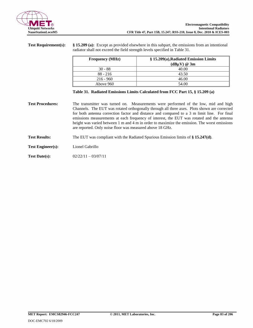
Electromagnetic Compatibility
Ubiquiti Networks Intentional Radiators
NanoStationLocoM5 CFR Title 47, Part 15B, 15.247; RSS-210, Issue 8, Dec. 2010 & ICES-003
MET Report: EMCS82946-FCC247 © 2011, MET Laboratories, Inc. Page 83 of 206
DOC-EMC702 6/18/2009
Test Requirement(s): § 15.209 (a): Except as provided elsewhere in this subpart, the emissions from an intentional
radiator shall not exceed the field strength levels specified in Table 31.
Frequency (MHz) § 15.209(a),Radiated Emission Limits
(dBV) @ 3m
30 - 88 40.00
88 - 216 43.50
216 - 960 46.00
Above 960 54.00
Table 31. Radiated Emissions Limits Calculated from FCC Part 15, § 15.209 (a)
Test Procedures: The transmitter was turned on. Measurements were performed of the low, mid and high
Channels. The EUT was rotated orthogonally through all three axes. Plots shown are corrected
for both antenna correction factor and distance and compared to a 3 m limit line. For final
emissions measurements at each frequency of interest, the EUT was rotated and the antenna
height was varied between 1 m and 4 m in order to maximize the emission. The worst emissions
are reported. Only noise floor was measured above 18 GHz.
Test Results: The EUT was compliant with the Radiated Spurious Emission limits of § 15.247(d).
Test Engineer(s): Lionel Gabrillo
Test Date(s): 02/22/11 – 03/07/11
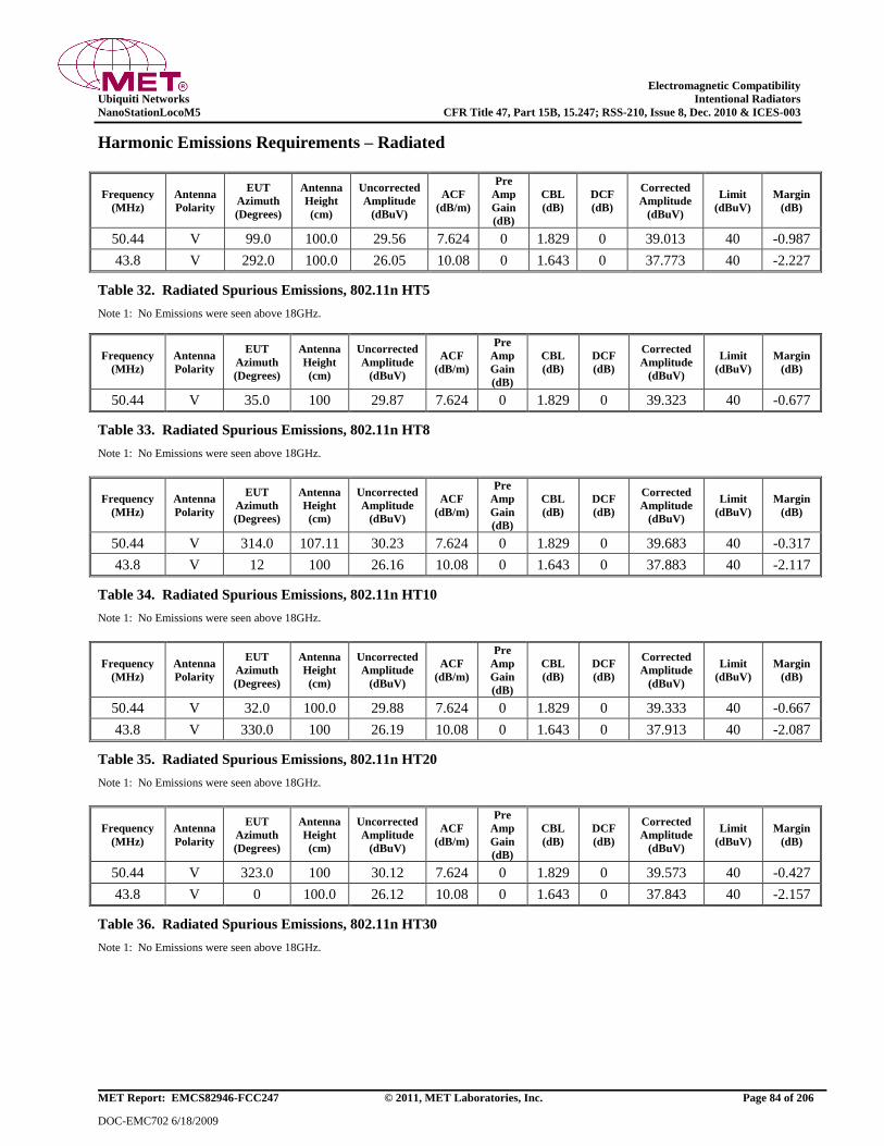
Electromagnetic Compatibility
Ubiquiti Networks Intentional Radiators
NanoStationLocoM5 CFR Title 47, Part 15B, 15.247; RSS-210, Issue 8, Dec. 2010 & ICES-003
MET Report: EMCS82946-FCC247 © 2011, MET Laboratories, Inc. Page 84 of 206
DOC-EMC702 6/18/2009
Harmonic Emissions Requirements – Radiated
Frequency
(MHz)
Antenna
Polarity
EUT
Azimuth
(Degrees)
Antenna
Height
(cm)
Uncorrected
Amplitude
(dBuV)
ACF
(dB/m)
Pre
Amp
Gain
(dB)
CBL
(dB)
DCF
(dB)
Corrected
Amplitude
(dBuV)
Limit
(dBuV)
Margin
(dB)
50.44 V 99.0 100.0 29.56 7.624 0 1.829 0 39.013 40 -0.987
43.8 V 292.0 100.0 26.05 10.08 0 1.643 0 37.773 40 -2.227
Table 32. Radiated Spurious Emissions, 802.11n HT5
Note 1: No Emissions were seen above 18GHz.
Frequency
(MHz)
Antenna
Polarity
EUT
Azimuth
(Degrees)
Antenna
Height
(cm)
Uncorrected
Amplitude
(dBuV)
ACF
(dB/m)
Pre
Amp
Gain
(dB)
CBL
(dB)
DCF
(dB)
Corrected
Amplitude
(dBuV)
Limit
(dBuV)
Margin
(dB)
50.44 V 35.0 100 29.87 7.624 0 1.829 0 39.323 40 -0.677
Table 33. Radiated Spurious Emissions, 802.11n HT8
Note 1: No Emissions were seen above 18GHz.
Frequency
(MHz)
Antenna
Polarity
EUT
Azimuth
(Degrees)
Antenna
Height
(cm)
Uncorrected
Amplitude
(dBuV)
ACF
(dB/m)
Pre
Amp
Gain
(dB)
CBL
(dB)
DCF
(dB)
Corrected
Amplitude
(dBuV)
Limit
(dBuV)
Margin
(dB)
50.44 V 314.0 107.11 30.23 7.624 0 1.829 0 39.683 40 -0.317
43.8 V 12 100 26.16 10.08 0 1.643 0 37.883 40 -2.117
Table 34. Radiated Spurious Emissions, 802.11n HT10
Note 1: No Emissions were seen above 18GHz.
Frequency
(MHz)
Antenna
Polarity
EUT
Azimuth
(Degrees)
Antenna
Height
(cm)
Uncorrected
Amplitude
(dBuV)
ACF
(dB/m)
Pre
Amp
Gain
(dB)
CBL
(dB)
DCF
(dB)
Corrected
Amplitude
(dBuV)
Limit
(dBuV)
Margin
(dB)
50.44 V 32.0 100.0 29.88 7.624 0 1.829 0 39.333 40 -0.667
43.8 V 330.0 100 26.19 10.08 0 1.643 0 37.913 40 -2.087
Table 35. Radiated Spurious Emissions, 802.11n HT20
Note 1: No Emissions were seen above 18GHz.
Frequency
(MHz)
Antenna
Polarity
EUT
Azimuth
(Degrees)
Antenna
Height
(cm)
Uncorrected
Amplitude
(dBuV)
ACF
(dB/m)
Pre
Amp
Gain
(dB)
CBL
(dB)
DCF
(dB)
Corrected
Amplitude
(dBuV)
Limit
(dBuV)
Margin
(dB)
50.44 V 323.0 100 30.12 7.624 0 1.829 0 39.573 40 -0.427
43.8 V 0 100.0 26.12 10.08 0 1.643 0 37.843 40 -2.157
Table 36. Radiated Spurious Emissions, 802.11n HT30
Note 1: No Emissions were seen above 18GHz.
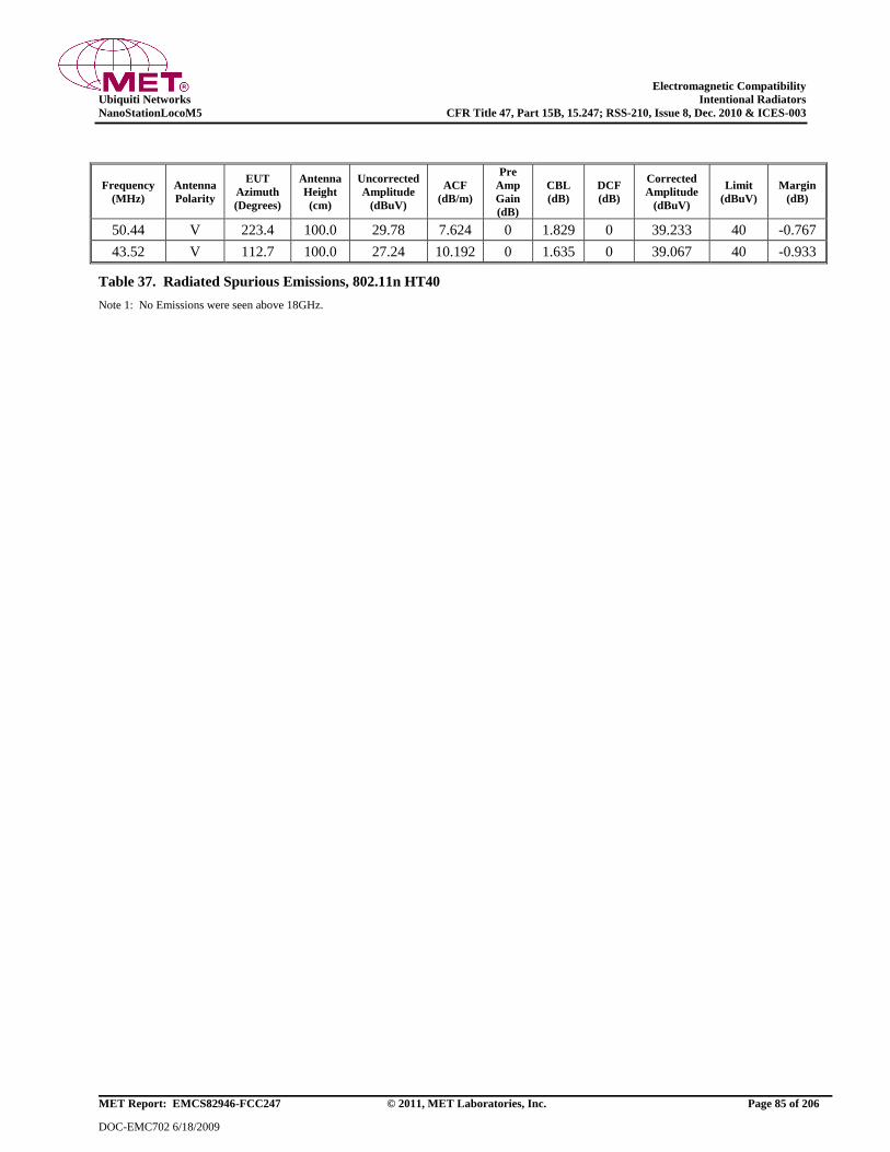
Electromagnetic Compatibility
Ubiquiti Networks Intentional Radiators
NanoStationLocoM5 CFR Title 47, Part 15B, 15.247; RSS-210, Issue 8, Dec. 2010 & ICES-003
MET Report: EMCS82946-FCC247 © 2011, MET Laboratories, Inc. Page 85 of 206
DOC-EMC702 6/18/2009
Frequency
(MHz)
Antenna
Polarity
EUT
Azimuth
(Degrees)
Antenna
Height
(cm)
Uncorrected
Amplitude
(dBuV)
ACF
(dB/m)
Pre
Amp
Gain
(dB)
CBL
(dB)
DCF
(dB)
Corrected
Amplitude
(dBuV)
Limit
(dBuV)
Margin
(dB)
50.44 V 223.4 100.0 29.78 7.624 0 1.829 0 39.233 40 -0.767
43.52 V 112.7 100.0 27.24 10.192 0 1.635 0 39.067 40 -0.933
Table 37. Radiated Spurious Emissions, 802.11n HT40
Note 1: No Emissions were seen above 18GHz.
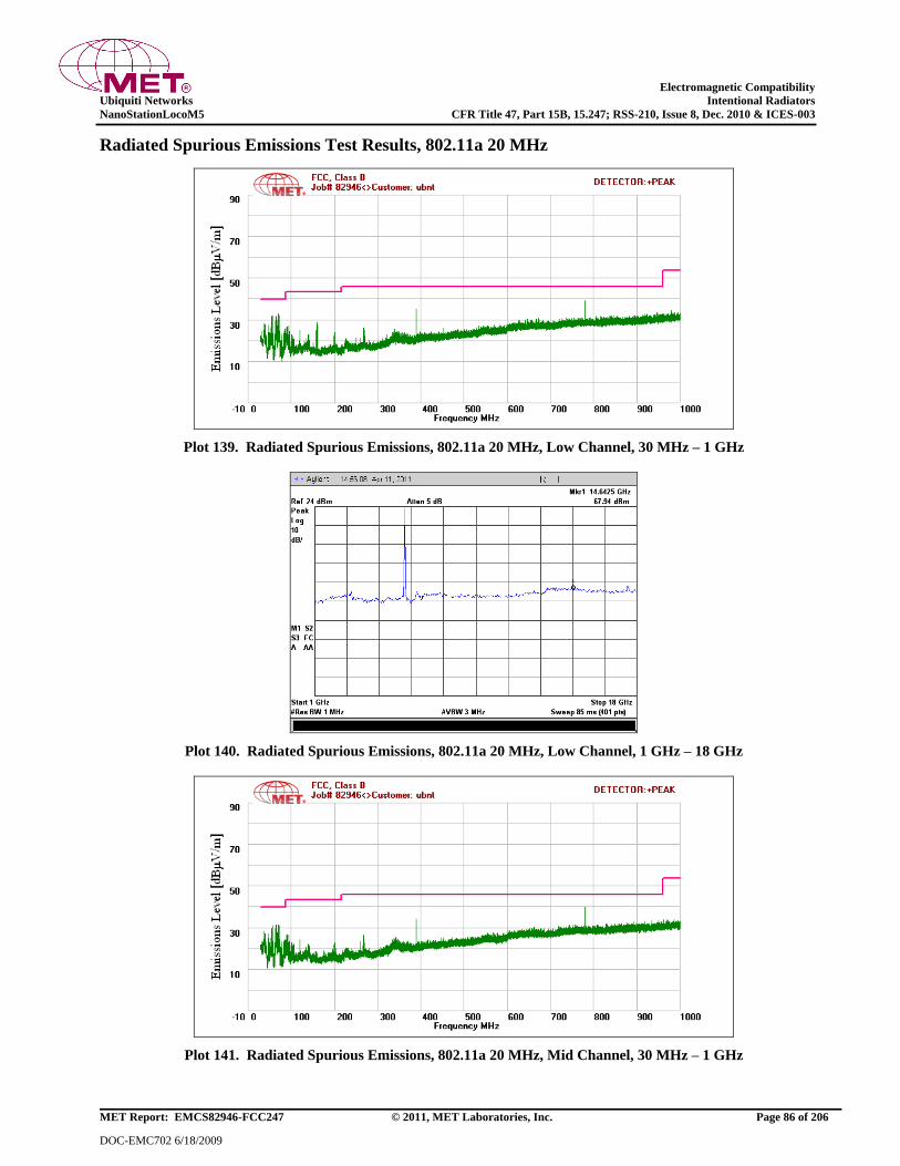
Electromagnetic Compatibility
Ubiquiti Networks Intentional Radiators
NanoStationLocoM5 CFR Title 47, Part 15B, 15.247; RSS-210, Issue 8, Dec. 2010 & ICES-003
MET Report: EMCS82946-FCC247 © 2011, MET Laboratories, Inc. Page 86 of 206
DOC-EMC702 6/18/2009
Radiated Spurious Emissions Test Results, 802.11a 20 MHz
Plot 139. Radiated Spurious Emissions, 802.11a 20 MHz, Low Channel, 30 MHz – 1 GHz
Plot 140. Radiated Spurious Emissions, 802.11a 20 MHz, Low Channel, 1 GHz – 18 GHz
Plot 141. Radiated Spurious Emissions, 802.11a 20 MHz, Mid Channel, 30 MHz – 1 GHz
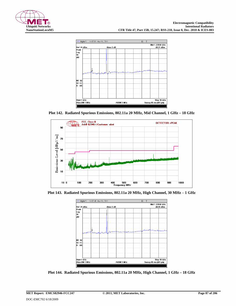
Electromagnetic Compatibility
Ubiquiti Networks Intentional Radiators
NanoStationLocoM5 CFR Title 47, Part 15B, 15.247; RSS-210, Issue 8, Dec. 2010 & ICES-003
MET Report: EMCS82946-FCC247 © 2011, MET Laboratories, Inc. Page 87 of 206
DOC-EMC702 6/18/2009
Plot 142. Radiated Spurious Emissions, 802.11a 20 MHz, Mid Channel, 1 GHz – 18 GHz
Plot 143. Radiated Spurious Emissions, 802.11a 20 MHz, High Channel, 30 MHz – 1 GHz
Plot 144. Radiated Spurious Emissions, 802.11a 20 MHz, High Channel, 1 GHz – 18 GHz
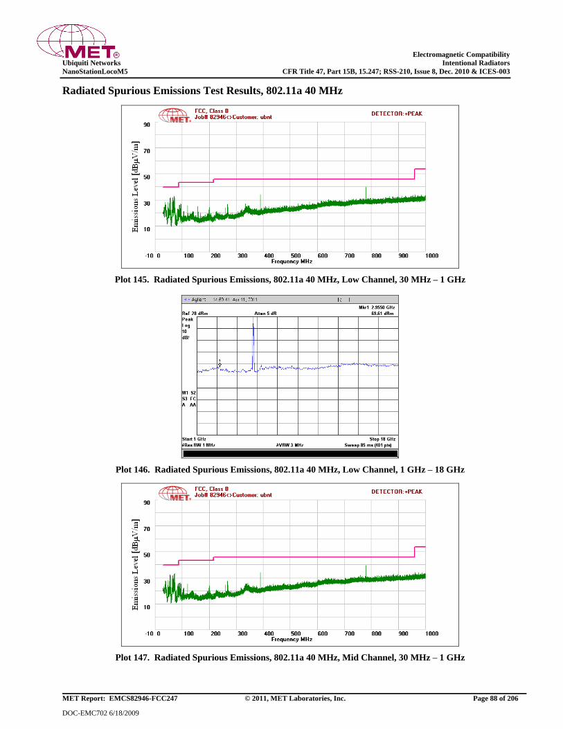
Electromagnetic Compatibility
Ubiquiti Networks Intentional Radiators
NanoStationLocoM5 CFR Title 47, Part 15B, 15.247; RSS-210, Issue 8, Dec. 2010 & ICES-003
MET Report: EMCS82946-FCC247 © 2011, MET Laboratories, Inc. Page 88 of 206
DOC-EMC702 6/18/2009
Radiated Spurious Emissions Test Results, 802.11a 40 MHz
Plot 145. Radiated Spurious Emissions, 802.11a 40 MHz, Low Channel, 30 MHz – 1 GHz
Plot 146. Radiated Spurious Emissions, 802.11a 40 MHz, Low Channel, 1 GHz – 18 GHz
Plot 147. Radiated Spurious Emissions, 802.11a 40 MHz, Mid Channel, 30 MHz – 1 GHz

Electromagnetic Compatibility
Ubiquiti Networks Intentional Radiators
NanoStationLocoM5 CFR Title 47, Part 15B, 15.247; RSS-210, Issue 8, Dec. 2010 & ICES-003
MET Report: EMCS82946-FCC247 © 2011, MET Laboratories, Inc. Page 89 of 206
DOC-EMC702 6/18/2009
Plot 148. Radiated Spurious Emissions, 802.11a 40 MHz, Mid Channel, 1 GHz – 18 GHz
Plot 149. Radiated Spurious Emissions, 802.11a 40 MHz, High Channel, 30 MHz – 1 GHz
Plot 150. Radiated Spurious Emissions, 802.11a 40 MHz, High Channel, 1 GHz – 18 GHz
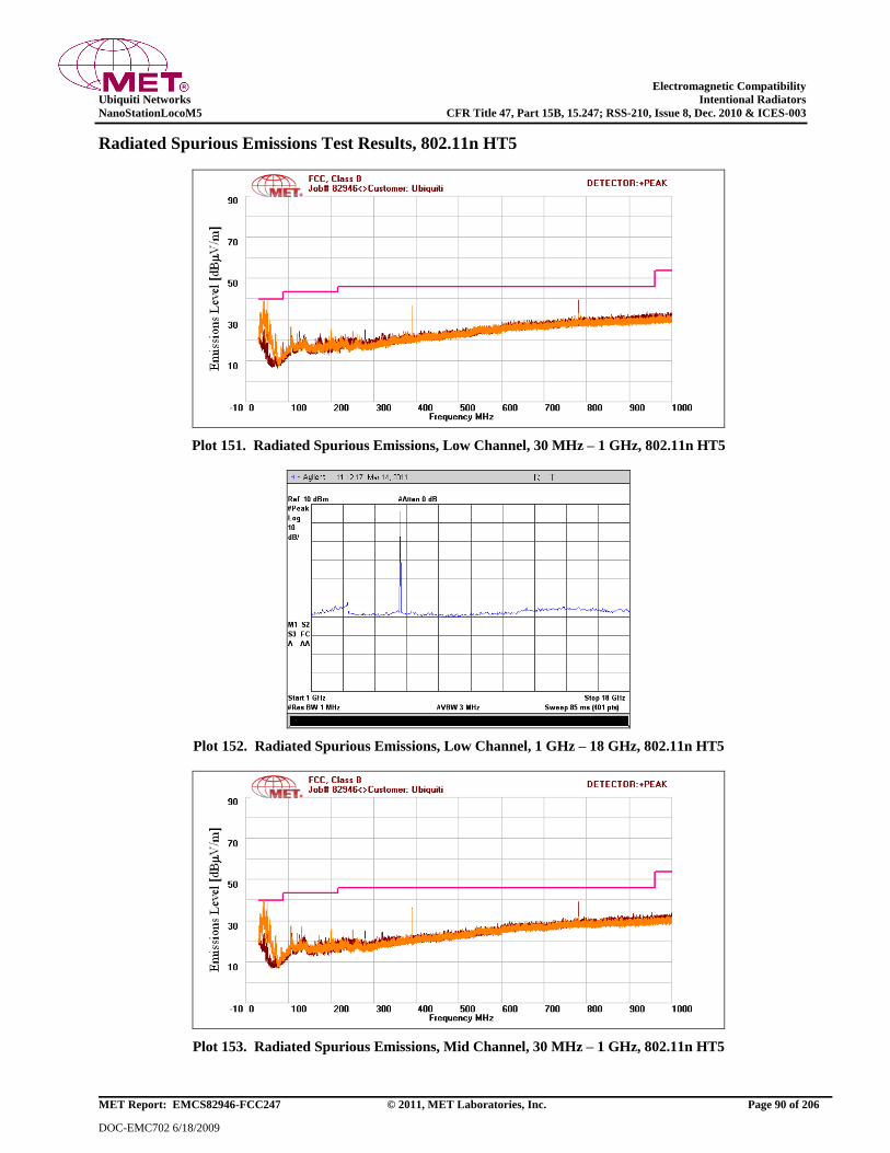
Electromagnetic Compatibility
Ubiquiti Networks Intentional Radiators
NanoStationLocoM5 CFR Title 47, Part 15B, 15.247; RSS-210, Issue 8, Dec. 2010 & ICES-003
MET Report: EMCS82946-FCC247 © 2011, MET Laboratories, Inc. Page 90 of 206
DOC-EMC702 6/18/2009
Radiated Spurious Emissions Test Results, 802.11n HT5
Plot 151. Radiated Spurious Emissions, Low Channel, 30 MHz – 1 GHz, 802.11n HT5
Plot 152. Radiated Spurious Emissions, Low Channel, 1 GHz – 18 GHz, 802.11n HT5
Plot 153. Radiated Spurious Emissions, Mid Channel, 30 MHz – 1 GHz, 802.11n HT5
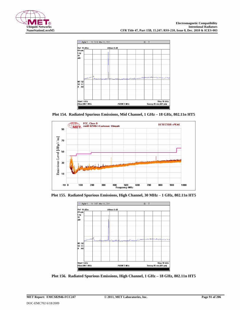
Electromagnetic Compatibility
Ubiquiti Networks Intentional Radiators
NanoStationLocoM5 CFR Title 47, Part 15B, 15.247; RSS-210, Issue 8, Dec. 2010 & ICES-003
MET Report: EMCS82946-FCC247 © 2011, MET Laboratories, Inc. Page 91 of 206
DOC-EMC702 6/18/2009
Plot 154. Radiated Spurious Emissions, Mid Channel, 1 GHz – 18 GHz, 802.11n HT5
Plot 155. Radiated Spurious Emissions, High Channel, 30 MHz – 1 GHz, 802.11n HT5
Plot 156. Radiated Spurious Emissions, High Channel, 1 GHz – 18 GHz, 802.11n HT5

Electromagnetic Compatibility
Ubiquiti Networks Intentional Radiators
NanoStationLocoM5 CFR Title 47, Part 15B, 15.247; RSS-210, Issue 8, Dec. 2010 & ICES-003
MET Report: EMCS82946-FCC247 © 2011, MET Laboratories, Inc. Page 92 of 206
DOC-EMC702 6/18/2009
Radiated Spurious Emissions Test Results, 802.11n HT8
Plot 157. Radiated Spurious Emissions, Low Channel, 30 MHz – 1 GHz, 802.11n HT8
Plot 158. Radiated Spurious Emissions, Low Channel, 1 GHz – 18 GHz, 802.11n HT8
Plot 159. Radiated Spurious Emissions, Mid Channel, 30 MHz – 1 GHz, 802.11n HT8
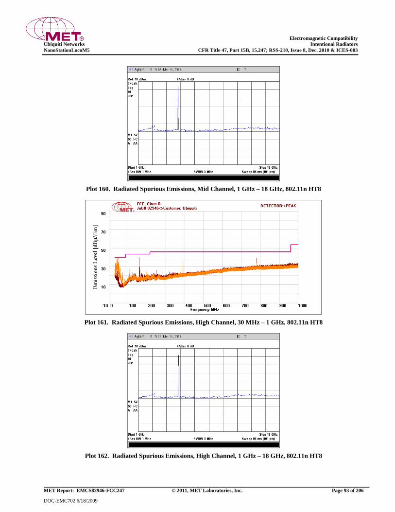
Electromagnetic Compatibility
Ubiquiti Networks Intentional Radiators
NanoStationLocoM5 CFR Title 47, Part 15B, 15.247; RSS-210, Issue 8, Dec. 2010 & ICES-003
MET Report: EMCS82946-FCC247 © 2011, MET Laboratories, Inc. Page 93 of 206
DOC-EMC702 6/18/2009
Plot 160. Radiated Spurious Emissions, Mid Channel, 1 GHz – 18 GHz, 802.11n HT8
Plot 161. Radiated Spurious Emissions, High Channel, 30 MHz – 1 GHz, 802.11n HT8
Plot 162. Radiated Spurious Emissions, High Channel, 1 GHz – 18 GHz, 802.11n HT8
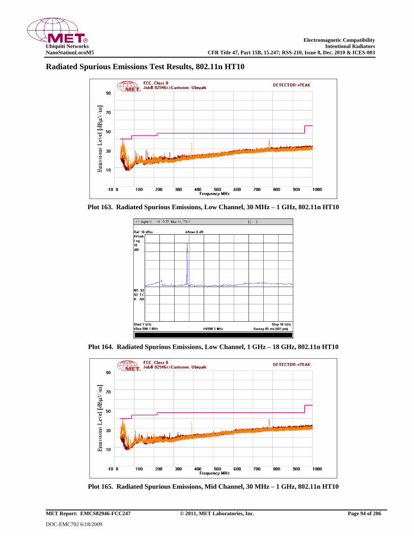
Electromagnetic Compatibility
Ubiquiti Networks Intentional Radiators
NanoStationLocoM5 CFR Title 47, Part 15B, 15.247; RSS-210, Issue 8, Dec. 2010 & ICES-003
MET Report: EMCS82946-FCC247 © 2011, MET Laboratories, Inc. Page 94 of 206
DOC-EMC702 6/18/2009
Radiated Spurious Emissions Test Results, 802.11n HT10
Plot 163. Radiated Spurious Emissions, Low Channel, 30 MHz – 1 GHz, 802.11n HT10
Plot 164. Radiated Spurious Emissions, Low Channel, 1 GHz – 18 GHz, 802.11n HT10
Plot 165. Radiated Spurious Emissions, Mid Channel, 30 MHz – 1 GHz, 802.11n HT10
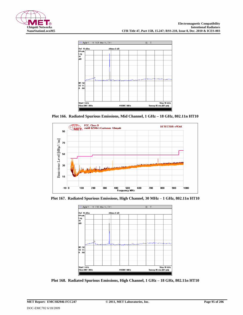
Electromagnetic Compatibility
Ubiquiti Networks Intentional Radiators
NanoStationLocoM5 CFR Title 47, Part 15B, 15.247; RSS-210, Issue 8, Dec. 2010 & ICES-003
MET Report: EMCS82946-FCC247 © 2011, MET Laboratories, Inc. Page 95 of 206
DOC-EMC702 6/18/2009
Plot 166. Radiated Spurious Emissions, Mid Channel, 1 GHz – 18 GHz, 802.11n HT10
Plot 167. Radiated Spurious Emissions, High Channel, 30 MHz – 1 GHz, 802.11n HT10
Plot 168. Radiated Spurious Emissions, High Channel, 1 GHz – 18 GHz, 802.11n HT10

Electromagnetic Compatibility
Ubiquiti Networks Intentional Radiators
NanoStationLocoM5 CFR Title 47, Part 15B, 15.247; RSS-210, Issue 8, Dec. 2010 & ICES-003
MET Report: EMCS82946-FCC247 © 2011, MET Laboratories, Inc. Page 96 of 206
DOC-EMC702 6/18/2009
Radiated Spurious Emissions Test Results, 802.11n HT20
Plot 169. Radiated Spurious Emissions, Low Channel, 30 MHz – 1 GHz, 802.11n HT20
Plot 170. Radiated Spurious Emissions, Low Channel, 1 GHz – 18 GHz, 802.11n HT20
Plot 171. Radiated Spurious Emissions, Mid Channel, 30 MHz – 1 GHz, 802.11n HT20
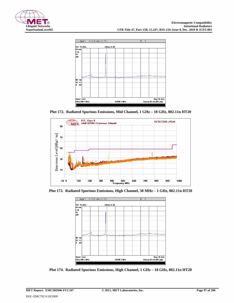
Electromagnetic Compatibility
Ubiquiti Networks Intentional Radiators
NanoStationLocoM5 CFR Title 47, Part 15B, 15.247; RSS-210, Issue 8, Dec. 2010 & ICES-003
MET Report: EMCS82946-FCC247 © 2011, MET Laboratories, Inc. Page 97 of 206
DOC-EMC702 6/18/2009
Plot 172. Radiated Spurious Emissions, Mid Channel, 1 GHz – 18 GHz, 802.11n HT20
Plot 173. Radiated Spurious Emissions, High Channel, 30 MHz – 1 GHz, 802.11n HT20
Plot 174. Radiated Spurious Emissions, High Channel, 1 GHz – 18 GHz, 802.11n HT20

Electromagnetic Compatibility
Ubiquiti Networks Intentional Radiators
NanoStationLocoM5 CFR Title 47, Part 15B, 15.247; RSS-210, Issue 8, Dec. 2010 & ICES-003
MET Report: EMCS82946-FCC247 © 2011, MET Laboratories, Inc. Page 98 of 206
DOC-EMC702 6/18/2009
Radiated Spurious Emissions Test Results, 802.11n HT30
Plot 175. Radiated Spurious Emissions, Low Channel, 30 MHz – 1 GHz, 802.11n HT30
Plot 176. Radiated Spurious Emissions, Low Channel, 1 GHz – 18 GHz, 802.11n HT30
Plot 177. Radiated Spurious Emissions, Mid Channel, 30 MHz – 1 GHz, 802.11n HT30
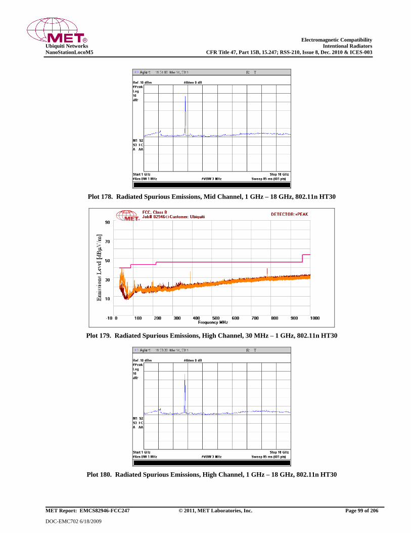
Electromagnetic Compatibility
Ubiquiti Networks Intentional Radiators
NanoStationLocoM5 CFR Title 47, Part 15B, 15.247; RSS-210, Issue 8, Dec. 2010 & ICES-003
MET Report: EMCS82946-FCC247 © 2011, MET Laboratories, Inc. Page 99 of 206
DOC-EMC702 6/18/2009
Plot 178. Radiated Spurious Emissions, Mid Channel, 1 GHz – 18 GHz, 802.11n HT30
Plot 179. Radiated Spurious Emissions, High Channel, 30 MHz – 1 GHz, 802.11n HT30
Plot 180. Radiated Spurious Emissions, High Channel, 1 GHz – 18 GHz, 802.11n HT30
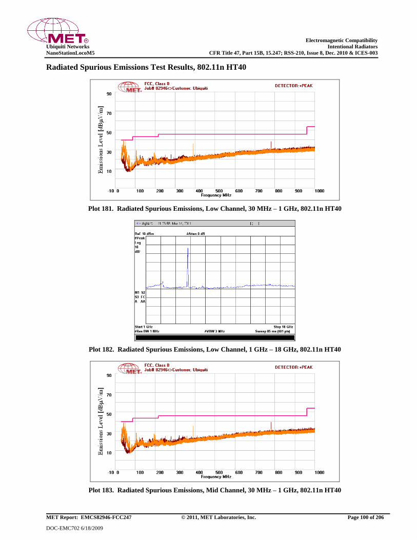
Electromagnetic Compatibility
Ubiquiti Networks Intentional Radiators
NanoStationLocoM5 CFR Title 47, Part 15B, 15.247; RSS-210, Issue 8, Dec. 2010 & ICES-003
MET Report: EMCS82946-FCC247 © 2011, MET Laboratories, Inc. Page 100 of 206
DOC-EMC702 6/18/2009
Radiated Spurious Emissions Test Results, 802.11n HT40
Plot 181. Radiated Spurious Emissions, Low Channel, 30 MHz – 1 GHz, 802.11n HT40
Plot 182. Radiated Spurious Emissions, Low Channel, 1 GHz – 18 GHz, 802.11n HT40
Plot 183. Radiated Spurious Emissions, Mid Channel, 30 MHz – 1 GHz, 802.11n HT40
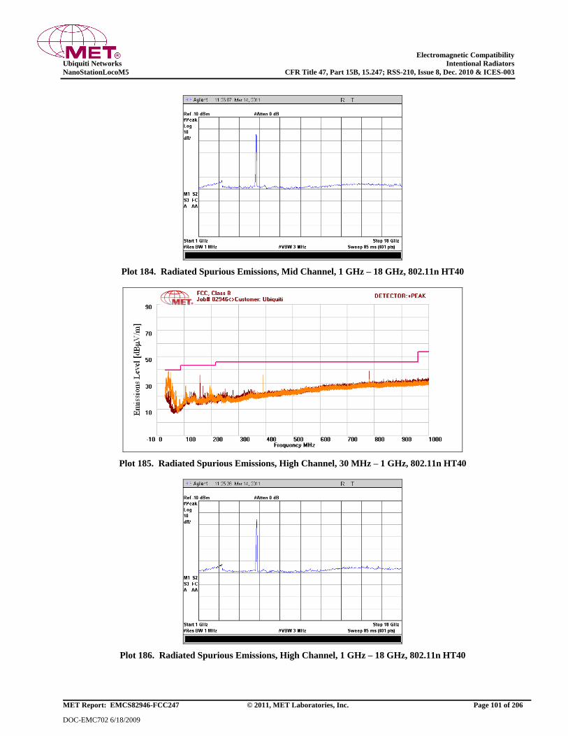
Electromagnetic Compatibility
Ubiquiti Networks Intentional Radiators
NanoStationLocoM5 CFR Title 47, Part 15B, 15.247; RSS-210, Issue 8, Dec. 2010 & ICES-003
MET Report: EMCS82946-FCC247 © 2011, MET Laboratories, Inc. Page 101 of 206
DOC-EMC702 6/18/2009
Plot 184. Radiated Spurious Emissions, Mid Channel, 1 GHz – 18 GHz, 802.11n HT40
Plot 185. Radiated Spurious Emissions, High Channel, 30 MHz – 1 GHz, 802.11n HT40
Plot 186. Radiated Spurious Emissions, High Channel, 1 GHz – 18 GHz, 802.11n HT40
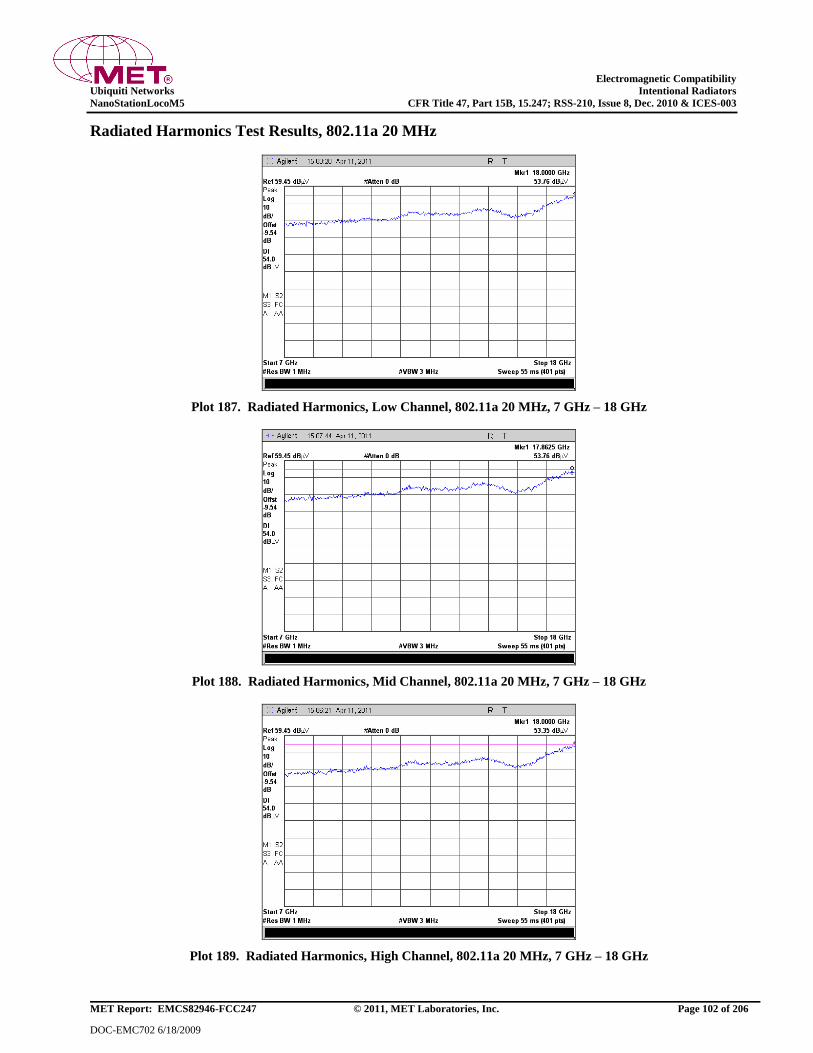
Electromagnetic Compatibility
Ubiquiti Networks Intentional Radiators
NanoStationLocoM5 CFR Title 47, Part 15B, 15.247; RSS-210, Issue 8, Dec. 2010 & ICES-003
MET Report: EMCS82946-FCC247 © 2011, MET Laboratories, Inc. Page 102 of 206
DOC-EMC702 6/18/2009
Radiated Harmonics Test Results, 802.11a 20 MHz
Plot 187. Radiated Harmonics, Low Channel, 802.11a 20 MHz, 7 GHz – 18 GHz
Plot 188. Radiated Harmonics, Mid Channel, 802.11a 20 MHz, 7 GHz – 18 GHz
Plot 189. Radiated Harmonics, High Channel, 802.11a 20 MHz, 7 GHz – 18 GHz
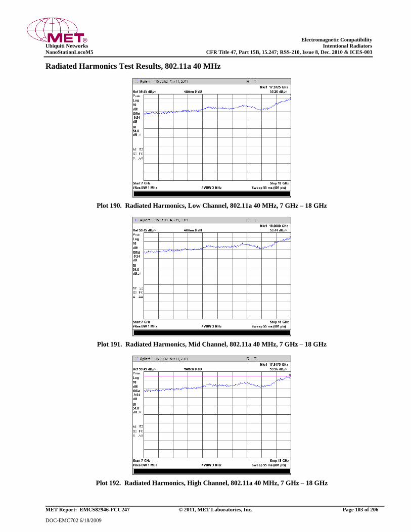
Electromagnetic Compatibility
Ubiquiti Networks Intentional Radiators
NanoStationLocoM5 CFR Title 47, Part 15B, 15.247; RSS-210, Issue 8, Dec. 2010 & ICES-003
MET Report: EMCS82946-FCC247 © 2011, MET Laboratories, Inc. Page 103 of 206
DOC-EMC702 6/18/2009
Radiated Harmonics Test Results, 802.11a 40 MHz
Plot 190. Radiated Harmonics, Low Channel, 802.11a 40 MHz, 7 GHz – 18 GHz
Plot 191. Radiated Harmonics, Mid Channel, 802.11a 40 MHz, 7 GHz – 18 GHz
Plot 192. Radiated Harmonics, High Channel, 802.11a 40 MHz, 7 GHz – 18 GHz

Electromagnetic Compatibility
Ubiquiti Networks Intentional Radiators
NanoStationLocoM5 CFR Title 47, Part 15B, 15.247; RSS-210, Issue 8, Dec. 2010 & ICES-003
MET Report: EMCS82946-FCC247 © 2011, MET Laboratories, Inc. Page 104 of 206
DOC-EMC702 6/18/2009
Radiated Harmonics Test Results, 802.11n HT5
15:56:09 Mar 14, 2011 R T
Ref 87.45 dBV #Atten 0 dB
#Peak
Log
10
dB/
Offst
-9.54
dB
Dl
54.0
dBV
W1 S2
S3 FC
A AA
Start 7 GHz
#Res BW 1 MHz #VBW 30 Hz
Stop 18 GHz
Sw eep 297.9 s (401 pts)
Plot 193. Radiated Harmonics, Low Channel, 7 GHz – 18 GHz, Average, 802.11n HT5
15:50:35 Mar 14, 2011 R T
Ref 87.45 dBV #Atten 0 dB
#Peak
Log
10
dB/
Offst
-9.54
dB
Dl
74.0
dBV
M1 S2
S3 FC
A AA
Start 7 GHz
#Res BW 1 MHz #VBW 3 MHz
Stop 18 GHz
Sw eep 55 ms (401 pts)
Plot 194. Radiated Harmonics, Low Channel, 7 GHz – 18 GHz, Peak, 802.11n HT5
15:49:41 Mar 14, 2011 R T
Ref 87.45 dBV #Atten 0 dB
#Peak
Log
10
dB/
Offst
-9.54
dB
Dl
54.0
dBV
W1 S2
S3 FC
A AA
Start 7 GHz
#Res BW 1 MHz #VBW 30 Hz
Stop 18 GHz
Sw eep 297.9 s (401 pts)
Plot 195. Radiated Harmonics, Mid Channel, 7 GHz – 18 GHz, Average, 802.11n HT5

Electromagnetic Compatibility
Ubiquiti Networks Intentional Radiators
NanoStationLocoM5 CFR Title 47, Part 15B, 15.247; RSS-210, Issue 8, Dec. 2010 & ICES-003
MET Report: EMCS82946-FCC247 © 2011, MET Laboratories, Inc. Page 105 of 206
DOC-EMC702 6/18/2009
15:43:54 Mar 14, 2011 R T
Ref 87.45 dBV #Atten 0 dB
#Peak
Log
10
dB/
Offst
-9.54
dB
Dl
74.0
dBV
M1 S2
S3 FC
A AA
Start 7 GHz
#Res BW 1 MHz #VBW 3 MHz
Stop 18 GHz
Sw eep 55 ms (401 pts)
Plot 196. Radiated Harmonics, Mid Channel, 7 GHz – 18 GHz, Peak, 802.11n HT5
15:43:11 Mar 14, 2011 R T
Ref 87.45 dBV #Atten 0 dB
#Peak
Log
10
dB/
Offst
-9.54
dB
Dl
54.0
dBV
W1 S2
S3 FC
A AA
Start 7 GHz
#Res BW 1 MHz #VBW 30 Hz
Stop 18 GHz
Sw eep 297.9 s (401 pts)
Plot 197. Radiated Harmonics, High Channel, 7 GHz – 18 GHz, Average, 802.11n HT5
15:37:25 Mar 14, 2011 R T
Ref 87.45 dBV #Atten 0 dB
#Peak
Log
10
dB/
Offst
-9.54
dB
Dl
74.0
dBV
M1 S2
S3 FC
A AA
Start 7 GHz
#Res BW 1 MHz #VBW 3 MHz
Stop 18 GHz
Sw eep 55 ms (401 pts)
Plot 198. Radiated Harmonics, High Channel, 7 GHz – 18 GHz, Peak, 802.11n HT5

Electromagnetic Compatibility
Ubiquiti Networks Intentional Radiators
NanoStationLocoM5 CFR Title 47, Part 15B, 15.247; RSS-210, Issue 8, Dec. 2010 & ICES-003
MET Report: EMCS82946-FCC247 © 2011, MET Laboratories, Inc. Page 106 of 206
DOC-EMC702 6/18/2009
Radiated Harmonics Test Results, 802.11n HT8
15:24:14 Mar 14, 2011 R T
Ref 87.45 dBV #Atten 0 dB
#Peak
Log
10
dB/
Offst
-9.54
dB
Dl
54.0
dBV
W1 S2
S3 FC
A AA
Start 7 GHz
#Res BW 1 MHz #VBW 30 Hz
Stop 18 GHz
Sw eep 297.9 s (401 pts)
Plot 199. Radiated Harmonics, Low Channel, 7 GHz – 18 GHz, Average, 802.11n HT8
15:18:39 Mar 14, 2011 R T
Ref 87.45 dBV #Atten 0 dB
#Peak
Log
10
dB/
Offst
-9.54
dB
Dl
74.0
dBV
M1 S2
S3 FC
A AA
Start 7 GHz
#Res BW 1 MHz #VBW 3 MHz
Stop 18 GHz
Sw eep 55 ms (401 pts)
Plot 200. Radiated Harmonics, Low Channel, 7 GHz – 18 GHz, Peak, 802.11n HT8
15:30:25 Mar 14, 2011 R T
Ref 87.45 dBV #Atten 0 dB
#Peak
Log
10
dB/
Offst
-9.54
dB
Dl
54.0
dBV
W1 S2
S3 FC
A AA
Start 7 GHz
#Res BW 1 MHz #VBW 30 Hz
Stop 18 GHz
Sw eep 297.9 s (401 pts)
Plot 201. Radiated Harmonics, Mid Channel, 7 GHz – 18 GHz, Average, 802.11n HT8
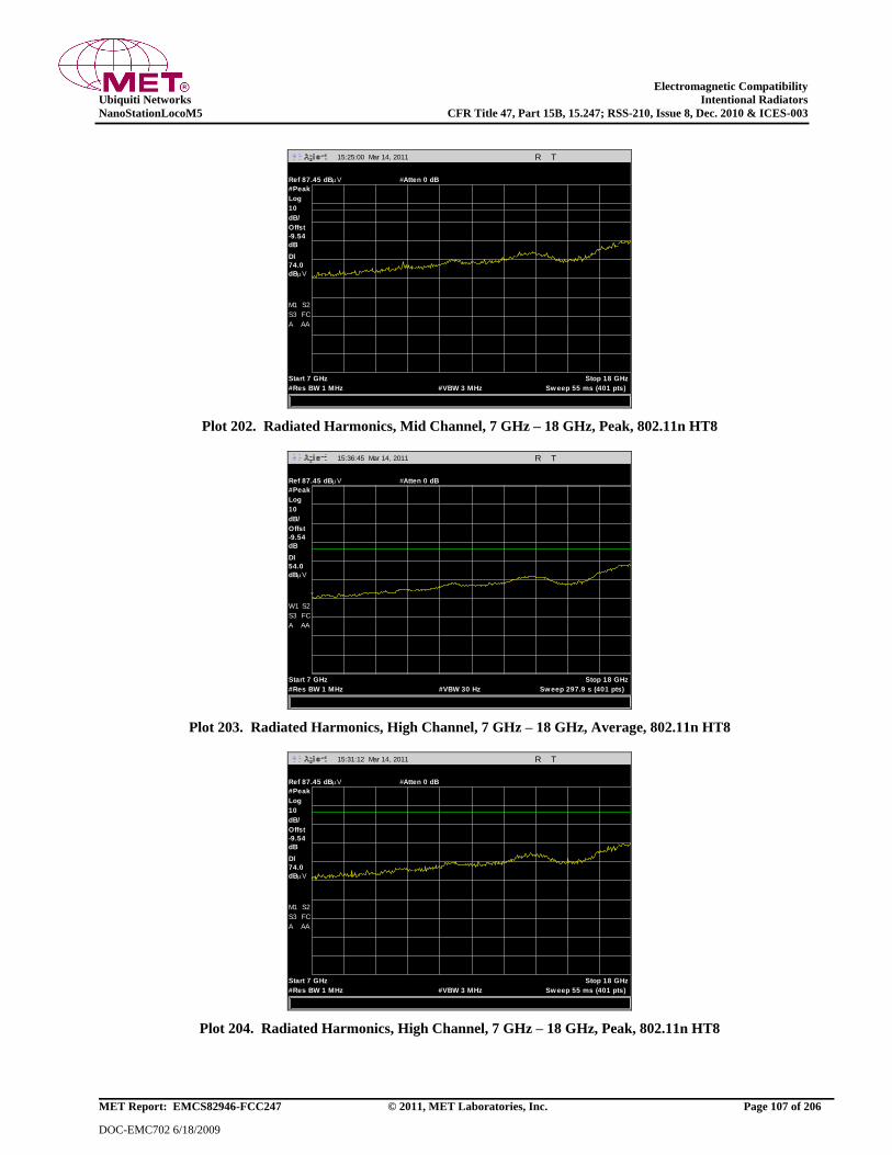
Electromagnetic Compatibility
Ubiquiti Networks Intentional Radiators
NanoStationLocoM5 CFR Title 47, Part 15B, 15.247; RSS-210, Issue 8, Dec. 2010 & ICES-003
MET Report: EMCS82946-FCC247 © 2011, MET Laboratories, Inc. Page 107 of 206
DOC-EMC702 6/18/2009
15:25:00 Mar 14, 2011 R T
Ref 87.45 dBV #Atten 0 dB
#Peak
Log
10
dB/
Offst
-9.54
dB
Dl
74.0
dBV
M1 S2
S3 FC
A AA
Start 7 GHz
#Res BW 1 MHz #VBW 3 MHz
Stop 18 GHz
Sw eep 55 ms (401 pts)
Plot 202. Radiated Harmonics, Mid Channel, 7 GHz – 18 GHz, Peak, 802.11n HT8
15:36:45 Mar 14, 2011 R T
Ref 87.45 dBV #Atten 0 dB
#Peak
Log
10
dB/
Offst
-9.54
dB
Dl
54.0
dBV
W1 S2
S3 FC
A AA
Start 7 GHz
#Res BW 1 MHz #VBW 30 Hz
Stop 18 GHz
Sw eep 297.9 s (401 pts)
Plot 203. Radiated Harmonics, High Channel, 7 GHz – 18 GHz, Average, 802.11n HT8
15:31:12 Mar 14, 2011 R T
Ref 87.45 dBV #Atten 0 dB
#Peak
Log
10
dB/
Offst
-9.54
dB
Dl
74.0
dBV
M1 S2
S3 FC
A AA
Start 7 GHz
#Res BW 1 MHz #VBW 3 MHz
Stop 18 GHz
Sw eep 55 ms (401 pts)
Plot 204. Radiated Harmonics, High Channel, 7 GHz – 18 GHz, Peak, 802.11n HT8

Electromagnetic Compatibility
Ubiquiti Networks Intentional Radiators
NanoStationLocoM5 CFR Title 47, Part 15B, 15.247; RSS-210, Issue 8, Dec. 2010 & ICES-003
MET Report: EMCS82946-FCC247 © 2011, MET Laboratories, Inc. Page 108 of 206
DOC-EMC702 6/18/2009
Radiated Harmonics Test Results, 802.11n HT10
15:17:02 Mar 14, 2011 R T
Ref 87.45 dBV #Atten 0 dB
#Peak
Log
10
dB/
Offst
-9.54
dB
Dl
54.0
dBV
W1 S2
S3 FC
A AA
Start 7 GHz
#Res BW 1 MHz #VBW 30 Hz
Stop 18 GHz
Sw eep 297.9 s (401 pts)
Plot 205. Radiated Harmonics, Low Channel, 7 GHz – 18 GHz, Average, 802.11n HT10
15:10:01 Mar 14, 2011 R T
Ref 87.45 dBV #Atten 0 dB
#Peak
Log
10
dB/
Offst
-9.54
dB
Dl
74.0
dBV
M1 S2
S3 FC
A AA
Start 7 GHz
#Res BW 1 MHz #VBW 3 MHz
Stop 18 GHz
Sw eep 55 ms (401 pts)
Plot 206. Radiated Harmonics, Low Channel, 7 GHz – 18 GHz, Peak, 802.11n HT10
15:08:37 Mar 14, 2011 R T
Ref 87.45 dBV #Atten 0 dB
#Peak
Log
10
dB/
Offst
-9.54
dB
Dl
54.0
dBV
W1 S2
S3 FC
A AA
Start 7 GHz
#Res BW 1 MHz #VBW 30 Hz
Stop 18 GHz
Sw eep 297.9 s (401 pts)
Plot 207. Radiated Harmonics, Mid Channel, 7 GHz – 18 GHz, Average, 802.11n HT10
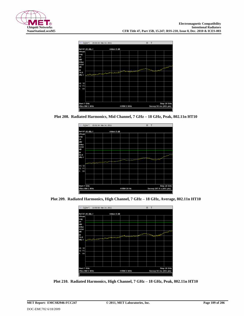
Electromagnetic Compatibility
Ubiquiti Networks Intentional Radiators
NanoStationLocoM5 CFR Title 47, Part 15B, 15.247; RSS-210, Issue 8, Dec. 2010 & ICES-003
MET Report: EMCS82946-FCC247 © 2011, MET Laboratories, Inc. Page 109 of 206
DOC-EMC702 6/18/2009
15:02:43 Mar 14, 2011 R T
Ref 87.45 dBV #Atten 0 dB
#Peak
Log
10
dB/
Offst
-9.54
dB
Dl
74.0
dBV
M1 S2
S3 FC
A AA
Start 7 GHz
#Res BW 1 MHz #VBW 3 MHz
Stop 18 GHz
Sw eep 55 ms (401 pts)
Plot 208. Radiated Harmonics, Mid Channel, 7 GHz – 18 GHz, Peak, 802.11n HT10
15:01:34 Mar 14, 2011 R T
Ref 87.45 dBV #Atten 0 dB
#Peak
Log
10
dB/
Offst
-9.54
dB
Dl
54.0
dBV
W1 S2
S3 FC
A AA
Start 7 GHz
#Res BW 1 MHz #VBW 30 Hz
Stop 18 GHz
Sw eep 297.9 s (401 pts)
Plot 209. Radiated Harmonics, High Channel, 7 GHz – 18 GHz, Average, 802.11n HT10
14:55:58 Mar 14, 2011 R T
Ref 87.45 dBV #Atten 0 dB
#Peak
Log
10
dB/
Offst
-9.54
dB
Dl
74.0
dBV
M1 S2
S3 FC
A AA
Start 7 GHz
#Res BW 1 MHz #VBW 3 MHz
Stop 18 GHz
Sw eep 55 ms (401 pts)
Plot 210. Radiated Harmonics, High Channel, 7 GHz – 18 GHz, Peak, 802.11n HT10
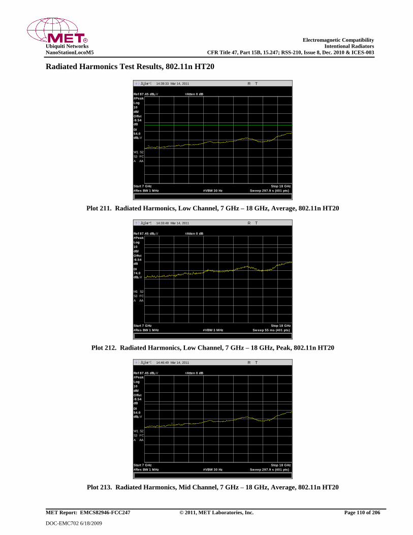
Electromagnetic Compatibility
Ubiquiti Networks Intentional Radiators
NanoStationLocoM5 CFR Title 47, Part 15B, 15.247; RSS-210, Issue 8, Dec. 2010 & ICES-003
MET Report: EMCS82946-FCC247 © 2011, MET Laboratories, Inc. Page 110 of 206
DOC-EMC702 6/18/2009
Radiated Harmonics Test Results, 802.11n HT20
14:39:33 Mar 14, 2011 R T
Ref 87.45 dBV #Atten 0 dB
#Peak
Log
10
dB/
Offst
-9.54
dB
Dl
54.0
dBV
W1 S2
S3 FC
A AA
Start 7 GHz
#Res BW 1 MHz #VBW 30 Hz
Stop 18 GHz
Sw eep 297.9 s (401 pts)
Plot 211. Radiated Harmonics, Low Channel, 7 GHz – 18 GHz, Average, 802.11n HT20
14:33:48 Mar 14, 2011 R T
Ref 87.45 dBV #Atten 0 dB
#Peak
Log
10
dB/
Offst
-9.54
dB
Dl
74.0
dBV
M1 S2
S3 FC
A AA
Start 7 GHz
#Res BW 1 MHz #VBW 3 MHz
Stop 18 GHz
Sw eep 55 ms (401 pts)
Plot 212. Radiated Harmonics, Low Channel, 7 GHz – 18 GHz, Peak, 802.11n HT20
14:46:49 Mar 14, 2011 R T
Ref 87.45 dBV #Atten 0 dB
#Peak
Log
10
dB/
Offst
-9.54
dB
Dl
54.0
dBV
W1 S2
S3 FC
A AA
Start 7 GHz
#Res BW 1 MHz #VBW 30 Hz
Stop 18 GHz
Sw eep 297.9 s (401 pts)
Plot 213. Radiated Harmonics, Mid Channel, 7 GHz – 18 GHz, Average, 802.11n HT20

Electromagnetic Compatibility
Ubiquiti Networks Intentional Radiators
NanoStationLocoM5 CFR Title 47, Part 15B, 15.247; RSS-210, Issue 8, Dec. 2010 & ICES-003
MET Report: EMCS82946-FCC247 © 2011, MET Laboratories, Inc. Page 111 of 206
DOC-EMC702 6/18/2009
14:40:24 Mar 14, 2011 R T
Ref 87.45 dBV #Atten 0 dB
#Peak
Log
10
dB/
Offst
-9.54
dB
Dl
74.0
dBV
M1 S2
S3 FC
A AA
Start 7 GHz
#Res BW 1 MHz #VBW 3 MHz
Stop 18 GHz
Sw eep 55 ms (401 pts)
Plot 214. Radiated Harmonics, Mid Channel, 7 GHz – 18 GHz, Peak, 802.11n HT20
14:53:35 Mar 14, 2011 R T
Ref 87.45 dBV #Atten 0 dB
#Peak
Log
10
dB/
Offst
-9.54
dB
Dl
54.0
dBV
W1 S2
S3 FC
A AA
Start 7 GHz
#Res BW 1 MHz #VBW 30 Hz
Stop 18 GHz
Sw eep 297.9 s (401 pts)
Plot 215. Radiated Harmonics, High Channel, 7 GHz – 18 GHz, Average, 802.11n HT20
14:47:56 Mar 14, 2011 R T
Ref 87.45 dBV #Atten 0 dB
#Peak
Log
10
dB/
Offst
-9.54
dB
Dl
74.0
dBV
M1 S2
S3 FC
A AA
Start 7 GHz
#Res BW 1 MHz #VBW 3 MHz
Stop 18 GHz
Sw eep 55 ms (401 pts)
Plot 216. Radiated Harmonics, High Channel, 7 GHz – 18 GHz, Peak, 802.11n HT20

Electromagnetic Compatibility
Ubiquiti Networks Intentional Radiators
NanoStationLocoM5 CFR Title 47, Part 15B, 15.247; RSS-210, Issue 8, Dec. 2010 & ICES-003
MET Report: EMCS82946-FCC247 © 2011, MET Laboratories, Inc. Page 112 of 206
DOC-EMC702 6/18/2009
Radiated Harmonics Test Results, 802.11n HT30
14:32:04 Mar 14, 2011 R T
Ref 87.45 dBV #Atten 0 dB
#Peak
Log
10
dB/
Offst
-9.54
dB
Dl
54.0
dBV
W1 S2
S3 FC
A AA
Start 7 GHz
#Res BW 1 MHz #VBW 30 Hz
Stop 18 GHz
Sw eep 297.9 s (401 pts)
Plot 217. Radiated Harmonics, Low Channel, 7 GHz – 18 GHz, Average, 802.11n HT30
14:26:26 Mar 14, 2011 R T
Ref 87.45 dBV #Atten 0 dB
#Peak
Log
10
dB/
Offst
-9.54
dB
Dl
74.0
dBV
M1 S2
S3 FC
A AA
Start 7 GHz
#Res BW 1 MHz #VBW 3 MHz
Stop 18 GHz
Sw eep 55 ms (401 pts)
Plot 218. Radiated Harmonics, Low Channel, 7 GHz – 18 GHz, Peak, 802.11n HT30
14:24:55 Mar 14, 2011 R T
Ref 87.45 dBV #Atten 0 dB
#Peak
Log
10
dB/
Offst
-9.54
dB
Dl
54.0
dBV
W1 S2
S3 FC
A AA
Start 7 GHz
#Res BW 1 MHz #VBW 30 Hz
Stop 18 GHz
Sw eep 297.9 s (401 pts)
Plot 219. Radiated Harmonics, Mid Channel, 7 GHz – 18 GHz, Average, 802.11n HT30

Electromagnetic Compatibility
Ubiquiti Networks Intentional Radiators
NanoStationLocoM5 CFR Title 47, Part 15B, 15.247; RSS-210, Issue 8, Dec. 2010 & ICES-003
MET Report: EMCS82946-FCC247 © 2011, MET Laboratories, Inc. Page 113 of 206
DOC-EMC702 6/18/2009
14:19:19 Mar 14, 2011 R T
Ref 87.45 dBV #Atten 0 dB
#Peak
Log
10
dB/
Offst
-9.54
dB
Dl
74.0
dBV
M1 S2
S3 FC
A AA
Start 7 GHz
#Res BW 1 MHz #VBW 3 MHz
Stop 18 GHz
Sw eep 55 ms (401 pts)
Plot 220. Radiated Harmonics, Mid Channel, 7 GHz – 18 GHz, Peak, 802.11n HT30
14:18:15 Mar 14, 2011 R T
Ref 87.45 dBV #Atten 0 dB
#Peak
Log
10
dB/
Offst
-9.54
dB
Dl
54.0
dBV
W1 S2
S3 FC
A AA
Start 7 GHz
#Res BW 1 MHz #VBW 30 Hz
Stop 18 GHz
Sw eep 297.9 s (401 pts)
Plot 221. Radiated Harmonics, High Channel, 7 GHz – 18 GHz, Average, 802.11n HT30
14:12:21 Mar 14, 2011 R T
Ref 87.45 dBV #Atten 0 dB
#Peak
Log
10
dB/
Offst
-9.54
dB
Dl
74.0
dBV
M1 S2
S3 FC
A AA
Start 7 GHz
#Res BW 1 MHz #VBW 3 MHz
Stop 18 GHz
Sw eep 55 ms (401 pts)
Plot 222. Radiated Harmonics, High Channel, 7 GHz – 18 GHz, Peak, 802.11n HT30

Electromagnetic Compatibility
Ubiquiti Networks Intentional Radiators
NanoStationLocoM5 CFR Title 47, Part 15B, 15.247; RSS-210, Issue 8, Dec. 2010 & ICES-003
MET Report: EMCS82946-FCC247 © 2011, MET Laboratories, Inc. Page 114 of 206
DOC-EMC702 6/18/2009
Radiated Harmonics Test Results, 802.11n HT40
13:54:32 Mar 14, 2011 R T
Ref 87.45 dBV #Atten 0 dB
#Peak
Log
10
dB/
Offst
-9.54
dB
Dl
54.0
dBV
W1 S2
S3 FC
A AA
Start 7 GHz
#Res BW 1 MHz #VBW 30 Hz
Stop 18 GHz
Sw eep 297.9 s (401 pts)
Plot 223. Radiated Harmonics, Low Channel, 7 GHz – 18 GHz, Average, 802.11n HT40
13:49:15 Mar 14, 2011 R T
Ref 87.45 dBV #Atten 0 dB
#Peak
Log
10
dB/
Offst
-9.54
dB
Dl
74.0
dBV
M1 S2
S3 FC
A AA
Start 7 GHz
#Res BW 1 MHz #VBW 3 MHz
Stop 18 GHz
Sw eep 55 ms (401 pts)
Plot 224. Radiated Harmonics, Low Channel, 7 GHz – 18 GHz, Peak, 802.11n HT40
14:04:25 Mar 14, 2011 R T
Ref 87.45 dBV #Atten 0 dB
#Peak
Log
10
dB/
Offst
-9.54
dB
Dl
54.0
dBV
W1 S2
S3 FC
A AA
Start 7 GHz
#Res BW 1 MHz #VBW 30 Hz
Stop 18 GHz
Sw eep 297.9 s (401 pts)
Plot 225. Radiated Harmonics, Mid Channel, 7 GHz – 18 GHz, Average, 802.11n HT40

Electromagnetic Compatibility
Ubiquiti Networks Intentional Radiators
NanoStationLocoM5 CFR Title 47, Part 15B, 15.247; RSS-210, Issue 8, Dec. 2010 & ICES-003
MET Report: EMCS82946-FCC247 © 2011, MET Laboratories, Inc. Page 115 of 206
DOC-EMC702 6/18/2009
13:58:54 Mar 14, 2011 R T
Ref 87.45 dBV #Atten 0 dB
#Peak
Log
10
dB/
Offst
-9.54
dB
Dl
74.0
dBV
M1 S2
S3 FC
A AA
Start 7 GHz
#Res BW 1 MHz #VBW 3 MHz
Stop 18 GHz
Sw eep 55 ms (401 pts)
Plot 226. Radiated Harmonics, Mid Channel, 7 GHz – 18 GHz, Peak, 802.11n HT40
14:11:15 Mar 14, 2011 R T
Ref 87.45 dBV #Atten 0 dB
#Peak
Log
10
dB/
Offst
-9.54
dB
Dl
54.0
dBV
W1 S2
S3 FC
A AA
Start 7 GHz
#Res BW 1 MHz #VBW 30 Hz
Stop 18 GHz
Sw eep 297.9 s (401 pts)
Plot 227. Radiated Harmonics, High Channel, 7 GHz – 18 GHz, Average, 802.11n HT40
14:05:34 Mar 14, 2011 R T
Ref 87.45 dBV #Atten 0 dB
#Peak
Log
10
dB/
Offst
-9.54
dB
Dl
74.0
dBV
M1 S2
S3 FC
A AA
Start 7 GHz
#Res BW 1 MHz #VBW 3 MHz
Stop 18 GHz
Sw eep 55 ms (401 pts)
Plot 228. Radiated Harmonics, High Channel, 7 GHz – 18 GHz, Peak, 802.11n HT40
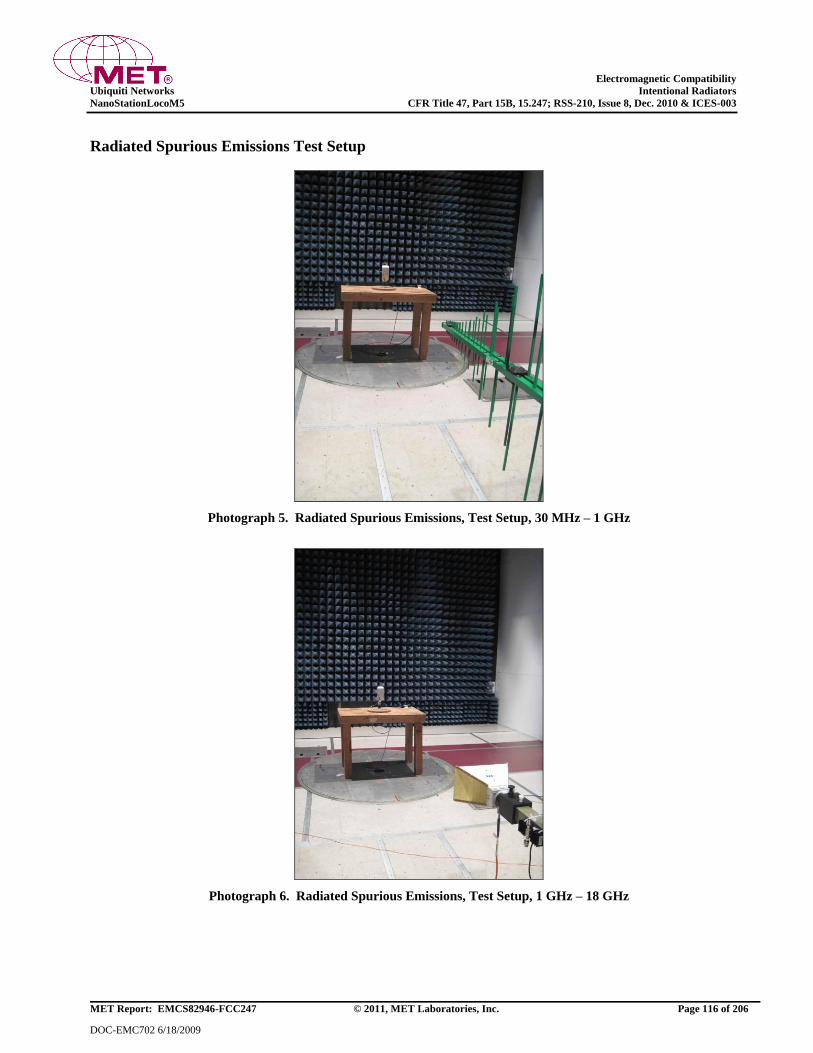
Electromagnetic Compatibility
Ubiquiti Networks Intentional Radiators
NanoStationLocoM5 CFR Title 47, Part 15B, 15.247; RSS-210, Issue 8, Dec. 2010 & ICES-003
MET Report: EMCS82946-FCC247 © 2011, MET Laboratories, Inc. Page 116 of 206
DOC-EMC702 6/18/2009
Radiated Spurious Emissions Test Setup
Photograph 5. Radiated Spurious Emissions, Test Setup, 30 MHz – 1 GHz
Photograph 6. Radiated Spurious Emissions, Test Setup, 1 GHz – 18 GHz
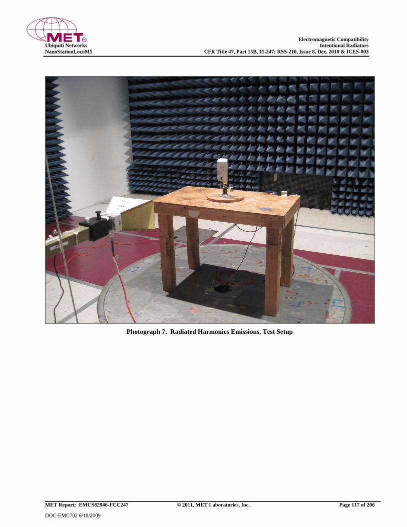
Electromagnetic Compatibility
Ubiquiti Networks Intentional Radiators
NanoStationLocoM5 CFR Title 47, Part 15B, 15.247; RSS-210, Issue 8, Dec. 2010 & ICES-003
MET Report: EMCS82946-FCC247 © 2011, MET Laboratories, Inc. Page 117 of 206
DOC-EMC702 6/18/2009
Photograph 7. Radiated Harmonics Emissions, Test Setup
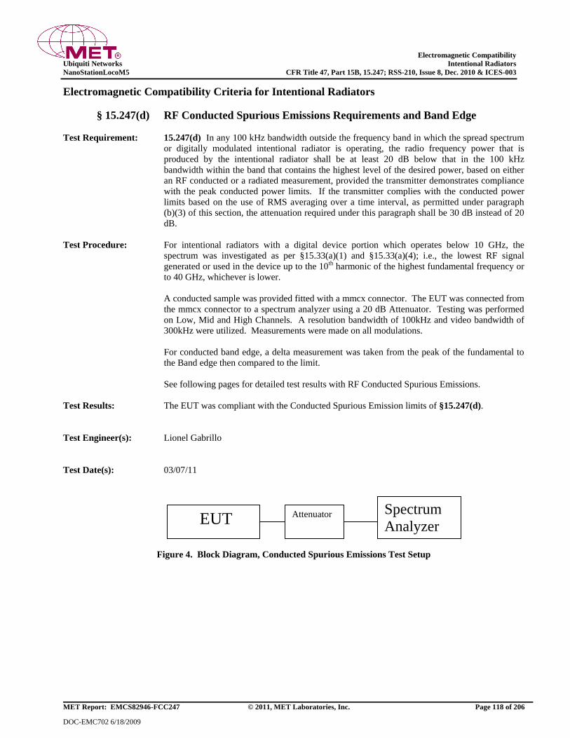
Electromagnetic Compatibility
Ubiquiti Networks Intentional Radiators
NanoStationLocoM5 CFR Title 47, Part 15B, 15.247; RSS-210, Issue 8, Dec. 2010 & ICES-003
MET Report: EMCS82946-FCC247 © 2011, MET Laboratories, Inc. Page 118 of 206
DOC-EMC702 6/18/2009
Electromagnetic Compatibility Criteria for Intentional Radiators
§ 15.247(d) RF Conducted Spurious Emissions Requirements and Band Edge
Test Requirement: 15.247(d) In any 100 kHz bandwidth outside the frequency band in which the spread spectrum
or digitally modulated intentional radiator is operating, the radio frequency power that is
produced by the intentional radiator shall be at least 20 dB below that in the 100 kHz
bandwidth within the band that contains the highest level of the desired power, based on either
an RF conducted or a radiated measurement, provided the transmitter demonstrates compliance
with the peak conducted power limits. If the transmitter complies with the conducted power
limits based on the use of RMS averaging over a time interval, as permitted under paragraph
(b)(3) of this section, the attenuation required under this paragraph shall be 30 dB instead of 20
dB.
Test Procedure: For intentional radiators with a digital device portion which operates below 10 GHz, the
spectrum was investigated as per §15.33(a)(1) and §15.33(a)(4); i.e., the lowest RF signal
generated or used in the device up to the 10th harmonic of the highest fundamental frequency or
to 40 GHz, whichever is lower.
A conducted sample was provided fitted with a mmcx connector. The EUT was connected from
the mmcx connector to a spectrum analyzer using a 20 dB Attenuator. Testing was performed
on Low, Mid and High Channels. A resolution bandwidth of 100kHz and video bandwidth of
300kHz were utilized. Measurements were made on all modulations.
For conducted band edge, a delta measurement was taken from the peak of the fundamental to
the Band edge then compared to the limit.
See following pages for detailed test results with RF Conducted Spurious Emissions.
Test Results: The EUT was compliant with the Conducted Spurious Emission limits of §15.247(d).
Test Engineer(s): Lionel Gabrillo
Test Date(s): 03/07/11
Figure 4. Block Diagram, Conducted Spurious Emissions Test Setup
EUT Attenuator Spectrum
Analyzer

Electromagnetic Compatibility
Ubiquiti Networks Intentional Radiators
NanoStationLocoM5 CFR Title 47, Part 15B, 15.247; RSS-210, Issue 8, Dec. 2010 & ICES-003
MET Report: EMCS82946-FCC247 © 2011, MET Laboratories, Inc. Page 119 of 206
DOC-EMC702 6/18/2009
Conducted Spurious Emissions Test Results, 802.11a 20 MHz
Plot 229. Conducted Spurious Emissions, Low Channel, 802.11a 20 MHz, 30 MHz – 1 GHz
Plot 230. Conducted Spurious Emissions, Low Channel, 802.11a 20 MHz, 1 GHz – 40 GHz
Plot 231. Conducted Spurious Emissions, Mid Channel, 802.11a 20 MHz, 30 MHz – 1 GHz
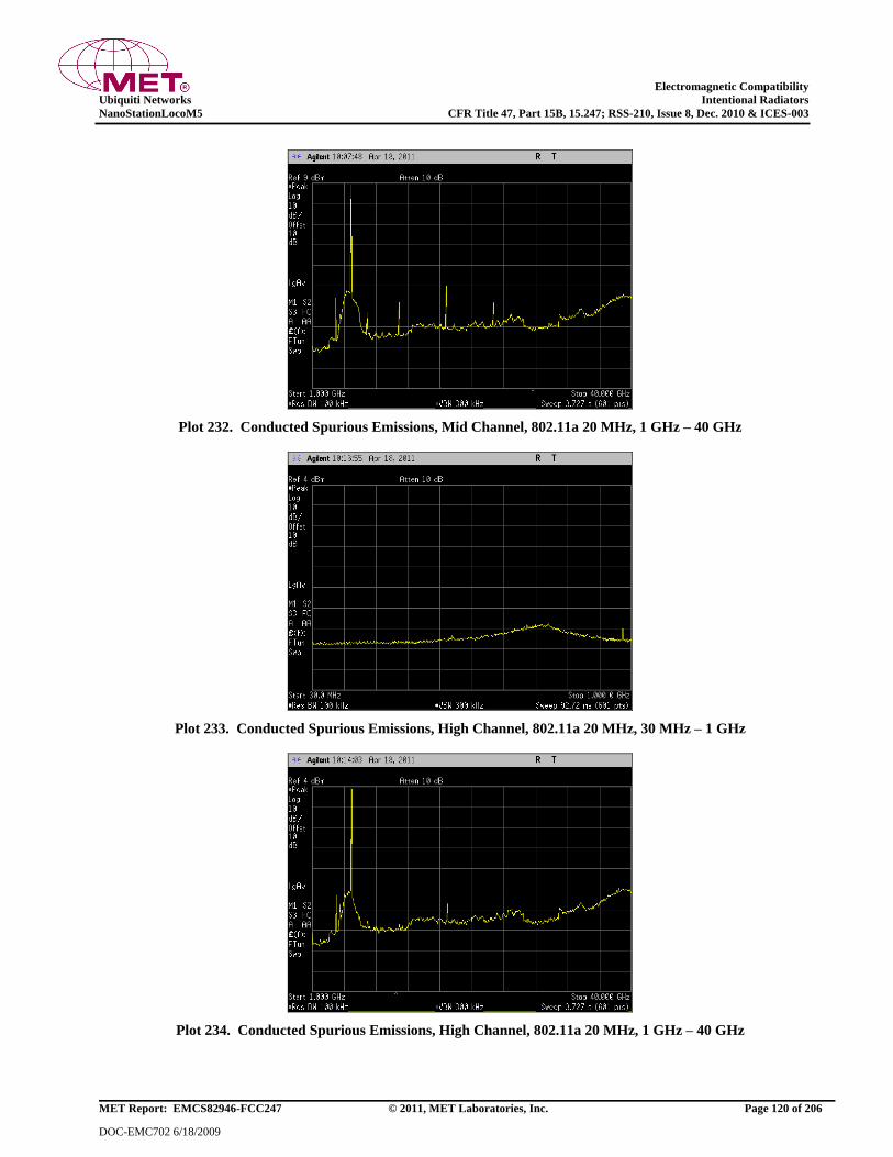
Electromagnetic Compatibility
Ubiquiti Networks Intentional Radiators
NanoStationLocoM5 CFR Title 47, Part 15B, 15.247; RSS-210, Issue 8, Dec. 2010 & ICES-003
MET Report: EMCS82946-FCC247 © 2011, MET Laboratories, Inc. Page 120 of 206
DOC-EMC702 6/18/2009
Plot 232. Conducted Spurious Emissions, Mid Channel, 802.11a 20 MHz, 1 GHz – 40 GHz
Plot 233. Conducted Spurious Emissions, High Channel, 802.11a 20 MHz, 30 MHz – 1 GHz
Plot 234. Conducted Spurious Emissions, High Channel, 802.11a 20 MHz, 1 GHz – 40 GHz
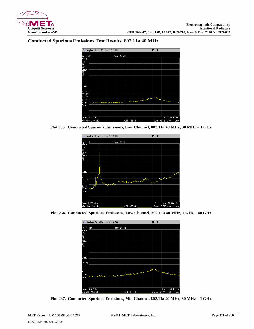
Electromagnetic Compatibility
Ubiquiti Networks Intentional Radiators
NanoStationLocoM5 CFR Title 47, Part 15B, 15.247; RSS-210, Issue 8, Dec. 2010 & ICES-003
MET Report: EMCS82946-FCC247 © 2011, MET Laboratories, Inc. Page 121 of 206
DOC-EMC702 6/18/2009
Conducted Spurious Emissions Test Results, 802.11a 40 MHz
Plot 235. Conducted Spurious Emissions, Low Channel, 802.11a 40 MHz, 30 MHz – 1 GHz
Plot 236. Conducted Spurious Emissions, Low Channel, 802.11a 40 MHz, 1 GHz – 40 GHz
Plot 237. Conducted Spurious Emissions, Mid Channel, 802.11a 40 MHz, 30 MHz – 1 GHz
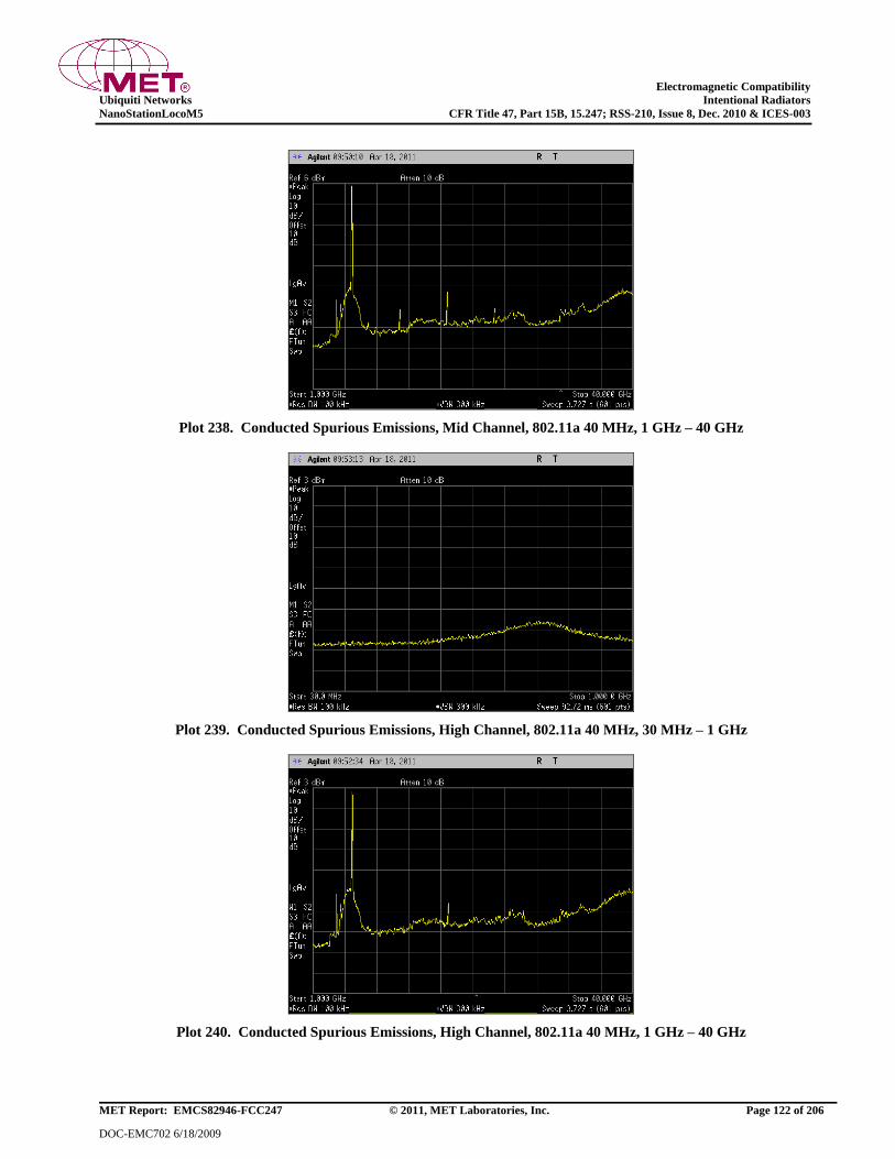
Electromagnetic Compatibility
Ubiquiti Networks Intentional Radiators
NanoStationLocoM5 CFR Title 47, Part 15B, 15.247; RSS-210, Issue 8, Dec. 2010 & ICES-003
MET Report: EMCS82946-FCC247 © 2011, MET Laboratories, Inc. Page 122 of 206
DOC-EMC702 6/18/2009
Plot 238. Conducted Spurious Emissions, Mid Channel, 802.11a 40 MHz, 1 GHz – 40 GHz
Plot 239. Conducted Spurious Emissions, High Channel, 802.11a 40 MHz, 30 MHz – 1 GHz
Plot 240. Conducted Spurious Emissions, High Channel, 802.11a 40 MHz, 1 GHz – 40 GHz
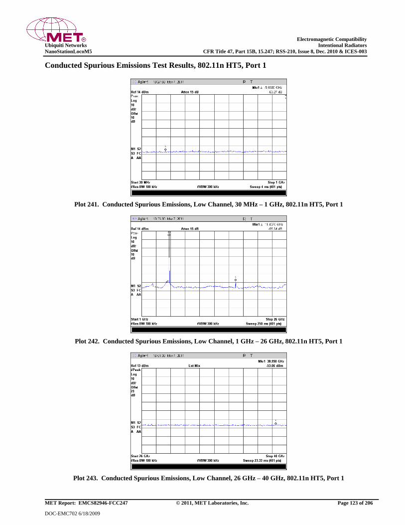
Electromagnetic Compatibility
Ubiquiti Networks Intentional Radiators
NanoStationLocoM5 CFR Title 47, Part 15B, 15.247; RSS-210, Issue 8, Dec. 2010 & ICES-003
MET Report: EMCS82946-FCC247 © 2011, MET Laboratories, Inc. Page 123 of 206
DOC-EMC702 6/18/2009
Conducted Spurious Emissions Test Results, 802.11n HT5, Port 1
Plot 241. Conducted Spurious Emissions, Low Channel, 30 MHz – 1 GHz, 802.11n HT5, Port 1
Plot 242. Conducted Spurious Emissions, Low Channel, 1 GHz – 26 GHz, 802.11n HT5, Port 1
Plot 243. Conducted Spurious Emissions, Low Channel, 26 GHz – 40 GHz, 802.11n HT5, Port 1

Electromagnetic Compatibility
Ubiquiti Networks Intentional Radiators
NanoStationLocoM5 CFR Title 47, Part 15B, 15.247; RSS-210, Issue 8, Dec. 2010 & ICES-003
MET Report: EMCS82946-FCC247 © 2011, MET Laboratories, Inc. Page 124 of 206
DOC-EMC702 6/18/2009
Plot 244. Conducted Spurious Emissions, Mid Channel, 30 MHz – 1 GHz, 802.11n HT5, Port 1
Plot 245. Conducted Spurious Emissions, Mid Channel, 1 GHz – 26 GHz, 802.11n HT5, Port 1
Plot 246. Conducted Spurious Emissions, Mid Channel, 26 GHz – 40 GHz, 802.11n HT5, Port 1

Electromagnetic Compatibility
Ubiquiti Networks Intentional Radiators
NanoStationLocoM5 CFR Title 47, Part 15B, 15.247; RSS-210, Issue 8, Dec. 2010 & ICES-003
MET Report: EMCS82946-FCC247 © 2011, MET Laboratories, Inc. Page 125 of 206
DOC-EMC702 6/18/2009
Plot 247. Conducted Spurious Emissions, High Channel, 30 MHz – 1 GHz, 802.11n HT5, Port 1
Plot 248. Conducted Spurious Emissions, High Channel, 1 GHz – 26 GHz, 802.11n HT5, Port 1
Plot 249. Conducted Spurious Emissions, High Channel, 26 GHz – 40 GHz, 802.11n HT5, Port 1
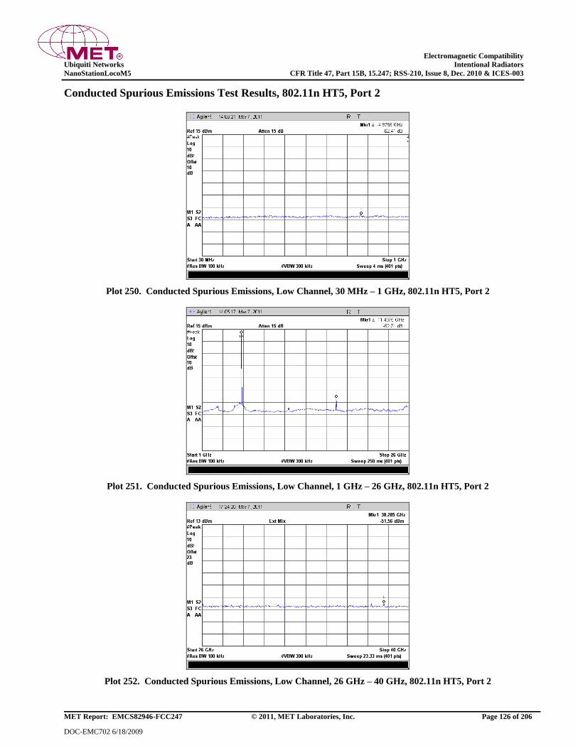
Electromagnetic Compatibility
Ubiquiti Networks Intentional Radiators
NanoStationLocoM5 CFR Title 47, Part 15B, 15.247; RSS-210, Issue 8, Dec. 2010 & ICES-003
MET Report: EMCS82946-FCC247 © 2011, MET Laboratories, Inc. Page 126 of 206
DOC-EMC702 6/18/2009
Conducted Spurious Emissions Test Results, 802.11n HT5, Port 2
Plot 250. Conducted Spurious Emissions, Low Channel, 30 MHz – 1 GHz, 802.11n HT5, Port 2
Plot 251. Conducted Spurious Emissions, Low Channel, 1 GHz – 26 GHz, 802.11n HT5, Port 2
Plot 252. Conducted Spurious Emissions, Low Channel, 26 GHz – 40 GHz, 802.11n HT5, Port 2

Electromagnetic Compatibility
Ubiquiti Networks Intentional Radiators
NanoStationLocoM5 CFR Title 47, Part 15B, 15.247; RSS-210, Issue 8, Dec. 2010 & ICES-003
MET Report: EMCS82946-FCC247 © 2011, MET Laboratories, Inc. Page 127 of 206
DOC-EMC702 6/18/2009
Plot 253. Conducted Spurious Emissions, Mid Channel, 30 MHz – 1 GHz, 802.11n HT5, Port 2
Plot 254. Conducted Spurious Emissions, Mid Channel, 1 GHz – 26 GHz, 802.11n HT5, Port 2
Plot 255. Conducted Spurious Emissions, Mid Channel, 26 GHz – 40 GHz, 802.11n HT5, Port 2
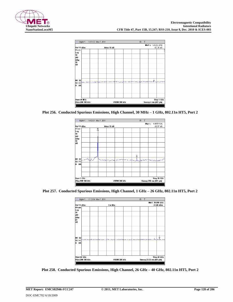
Electromagnetic Compatibility
Ubiquiti Networks Intentional Radiators
NanoStationLocoM5 CFR Title 47, Part 15B, 15.247; RSS-210, Issue 8, Dec. 2010 & ICES-003
MET Report: EMCS82946-FCC247 © 2011, MET Laboratories, Inc. Page 128 of 206
DOC-EMC702 6/18/2009
Plot 256. Conducted Spurious Emissions, High Channel, 30 MHz – 1 GHz, 802.11n HT5, Port 2
Plot 257. Conducted Spurious Emissions, High Channel, 1 GHz – 26 GHz, 802.11n HT5, Port 2
Plot 258. Conducted Spurious Emissions, High Channel, 26 GHz – 40 GHz, 802.11n HT5, Port 2

Electromagnetic Compatibility
Ubiquiti Networks Intentional Radiators
NanoStationLocoM5 CFR Title 47, Part 15B, 15.247; RSS-210, Issue 8, Dec. 2010 & ICES-003
MET Report: EMCS82946-FCC247 © 2011, MET Laboratories, Inc. Page 129 of 206
DOC-EMC702 6/18/2009
Conducted Spurious Emissions Test Results, 802.11n HT8, Port 1
Plot 259. Conducted Spurious Emissions, Low Channel, 30 MHz – 1 GHz, 802.11n HT8, Port 1
Plot 260. Conducted Spurious Emissions, Low Channel, 1 GHz – 26 GHz, 802.11n HT8, Port 1
Plot 261. Conducted Spurious Emissions, Low Channel, 26 GHz – 40 GHz, 802.11n HT8, Port 1
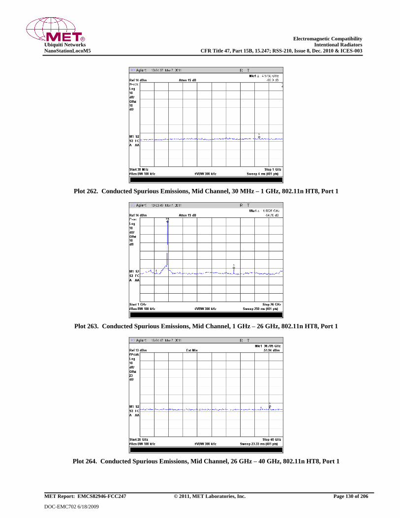
Electromagnetic Compatibility
Ubiquiti Networks Intentional Radiators
NanoStationLocoM5 CFR Title 47, Part 15B, 15.247; RSS-210, Issue 8, Dec. 2010 & ICES-003
MET Report: EMCS82946-FCC247 © 2011, MET Laboratories, Inc. Page 130 of 206
DOC-EMC702 6/18/2009
Plot 262. Conducted Spurious Emissions, Mid Channel, 30 MHz – 1 GHz, 802.11n HT8, Port 1
Plot 263. Conducted Spurious Emissions, Mid Channel, 1 GHz – 26 GHz, 802.11n HT8, Port 1
Plot 264. Conducted Spurious Emissions, Mid Channel, 26 GHz – 40 GHz, 802.11n HT8, Port 1
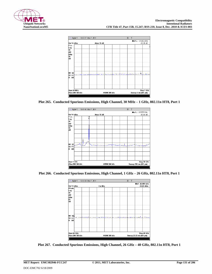
Electromagnetic Compatibility
Ubiquiti Networks Intentional Radiators
NanoStationLocoM5 CFR Title 47, Part 15B, 15.247; RSS-210, Issue 8, Dec. 2010 & ICES-003
MET Report: EMCS82946-FCC247 © 2011, MET Laboratories, Inc. Page 131 of 206
DOC-EMC702 6/18/2009
Plot 265. Conducted Spurious Emissions, High Channel, 30 MHz – 1 GHz, 802.11n HT8, Port 1
Plot 266. Conducted Spurious Emissions, High Channel, 1 GHz – 26 GHz, 802.11n HT8, Port 1
Plot 267. Conducted Spurious Emissions, High Channel, 26 GHz – 40 GHz, 802.11n HT8, Port 1

Electromagnetic Compatibility
Ubiquiti Networks Intentional Radiators
NanoStationLocoM5 CFR Title 47, Part 15B, 15.247; RSS-210, Issue 8, Dec. 2010 & ICES-003
MET Report: EMCS82946-FCC247 © 2011, MET Laboratories, Inc. Page 132 of 206
DOC-EMC702 6/18/2009
Conducted Spurious Emissions Test Results, 802.11n HT8, Port 2
Plot 268. Conducted Spurious Emissions, Low Channel, 30 MHz – 1 GHz, 802.11n HT8, Port 2
Plot 269. Conducted Spurious Emissions, Low Channel, 1 GHz – 26 GHz, 802.11n HT8, Port 2
Plot 270. Conducted Spurious Emissions, Low Channel, 26 GHz – 40 GHz, 802.11n HT8, Port 2
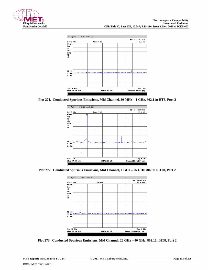
Electromagnetic Compatibility
Ubiquiti Networks Intentional Radiators
NanoStationLocoM5 CFR Title 47, Part 15B, 15.247; RSS-210, Issue 8, Dec. 2010 & ICES-003
MET Report: EMCS82946-FCC247 © 2011, MET Laboratories, Inc. Page 133 of 206
DOC-EMC702 6/18/2009
Plot 271. Conducted Spurious Emissions, Mid Channel, 30 MHz – 1 GHz, 802.11n HT8, Port 2
Plot 272. Conducted Spurious Emissions, Mid Channel, 1 GHz – 26 GHz, 802.11n HT8, Port 2
Plot 273. Conducted Spurious Emissions, Mid Channel, 26 GHz – 40 GHz, 802.11n HT8, Port 2
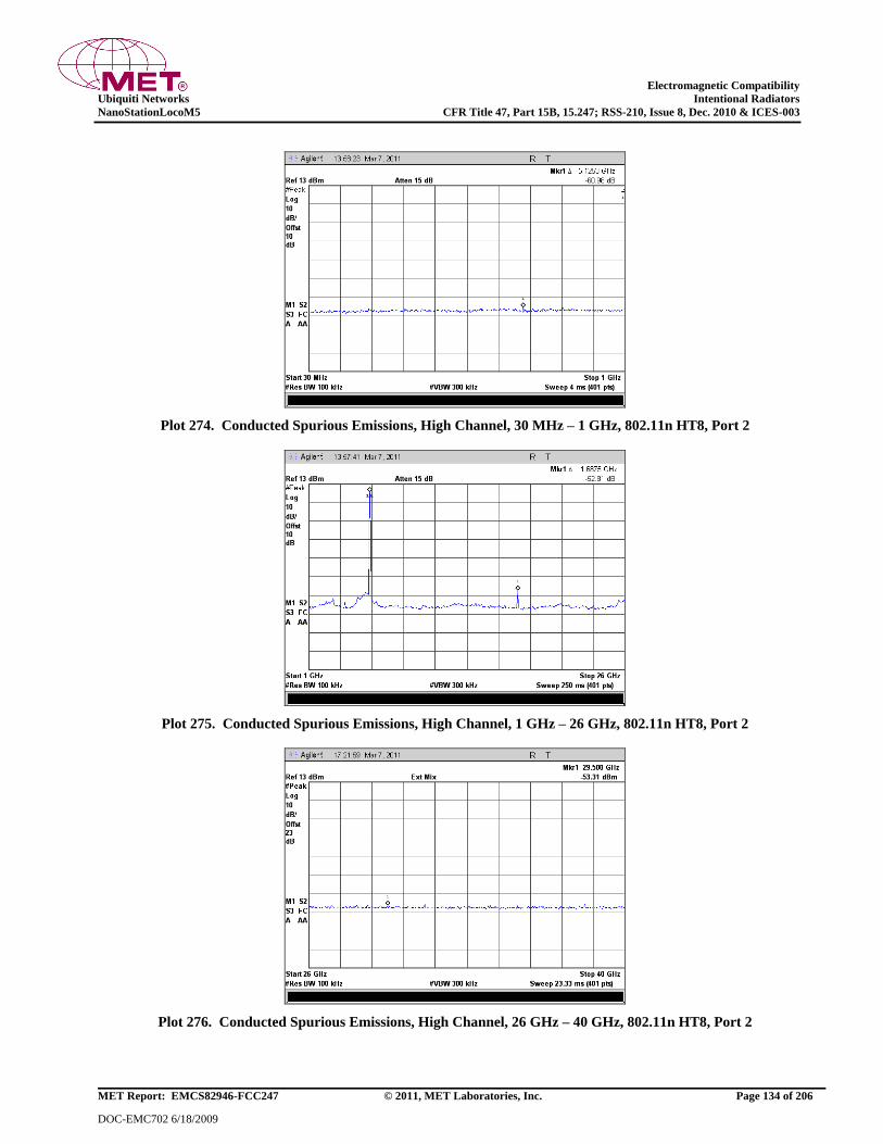
Electromagnetic Compatibility
Ubiquiti Networks Intentional Radiators
NanoStationLocoM5 CFR Title 47, Part 15B, 15.247; RSS-210, Issue 8, Dec. 2010 & ICES-003
MET Report: EMCS82946-FCC247 © 2011, MET Laboratories, Inc. Page 134 of 206
DOC-EMC702 6/18/2009
Plot 274. Conducted Spurious Emissions, High Channel, 30 MHz – 1 GHz, 802.11n HT8, Port 2
Plot 275. Conducted Spurious Emissions, High Channel, 1 GHz – 26 GHz, 802.11n HT8, Port 2
Plot 276. Conducted Spurious Emissions, High Channel, 26 GHz – 40 GHz, 802.11n HT8, Port 2
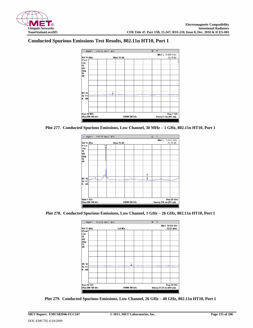
Electromagnetic Compatibility
Ubiquiti Networks Intentional Radiators
NanoStationLocoM5 CFR Title 47, Part 15B, 15.247; RSS-210, Issue 8, Dec. 2010 & ICES-003
MET Report: EMCS82946-FCC247 © 2011, MET Laboratories, Inc. Page 135 of 206
DOC-EMC702 6/18/2009
Conducted Spurious Emissions Test Results, 802.11n HT10, Port 1
Plot 277. Conducted Spurious Emissions, Low Channel, 30 MHz – 1 GHz, 802.11n HT10, Port 1
Plot 278. Conducted Spurious Emissions, Low Channel, 1 GHz – 26 GHz, 802.11n HT10, Port 1
Plot 279. Conducted Spurious Emissions, Low Channel, 26 GHz – 40 GHz, 802.11n HT10, Port 1
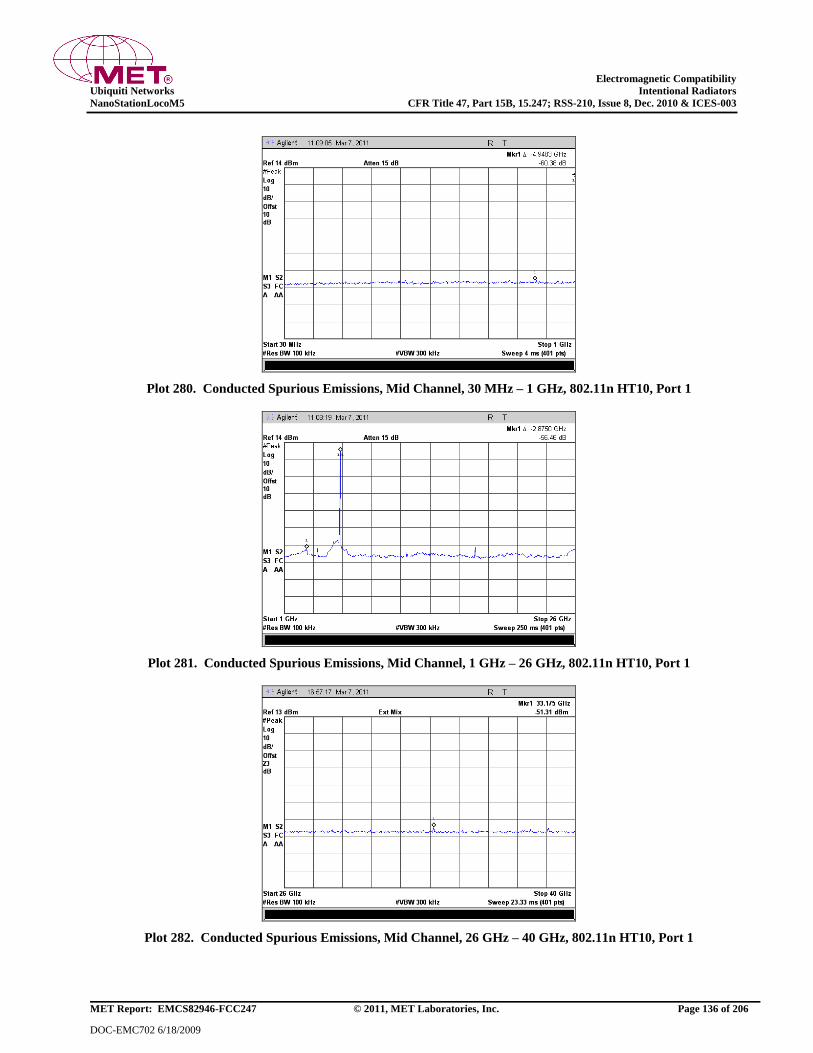
Electromagnetic Compatibility
Ubiquiti Networks Intentional Radiators
NanoStationLocoM5 CFR Title 47, Part 15B, 15.247; RSS-210, Issue 8, Dec. 2010 & ICES-003
MET Report: EMCS82946-FCC247 © 2011, MET Laboratories, Inc. Page 136 of 206
DOC-EMC702 6/18/2009
Plot 280. Conducted Spurious Emissions, Mid Channel, 30 MHz – 1 GHz, 802.11n HT10, Port 1
Plot 281. Conducted Spurious Emissions, Mid Channel, 1 GHz – 26 GHz, 802.11n HT10, Port 1
Plot 282. Conducted Spurious Emissions, Mid Channel, 26 GHz – 40 GHz, 802.11n HT10, Port 1

Electromagnetic Compatibility
Ubiquiti Networks Intentional Radiators
NanoStationLocoM5 CFR Title 47, Part 15B, 15.247; RSS-210, Issue 8, Dec. 2010 & ICES-003
MET Report: EMCS82946-FCC247 © 2011, MET Laboratories, Inc. Page 137 of 206
DOC-EMC702 6/18/2009
Plot 283. Conducted Spurious Emissions, High Channel, 30 MHz – 1 GHz, 802.11n HT10, Port 1
Plot 284. Conducted Spurious Emissions, High Channel, 1 GHz – 26 GHz, 802.11n HT10, Port 1
Plot 285. Conducted Spurious Emissions, High Channel, 26 GHz – 40 GHz, 802.11n HT10, Port 1

Electromagnetic Compatibility
Ubiquiti Networks Intentional Radiators
NanoStationLocoM5 CFR Title 47, Part 15B, 15.247; RSS-210, Issue 8, Dec. 2010 & ICES-003
MET Report: EMCS82946-FCC247 © 2011, MET Laboratories, Inc. Page 138 of 206
DOC-EMC702 6/18/2009
Conducted Spurious Emissions Test Results, 802.11n HT10, Port 2
Plot 286. Conducted Spurious Emissions, Low Channel, 30 MHz – 1 GHz, 802.11n HT10, Port 2
Plot 287. Conducted Spurious Emissions, Low Channel, 1 GHz – 26 GHz, 802.11n HT10, Port 2
Plot 288. Conducted Spurious Emissions, Low Channel, 26 GHz – 40 GHz, 802.11n HT10, Port 2
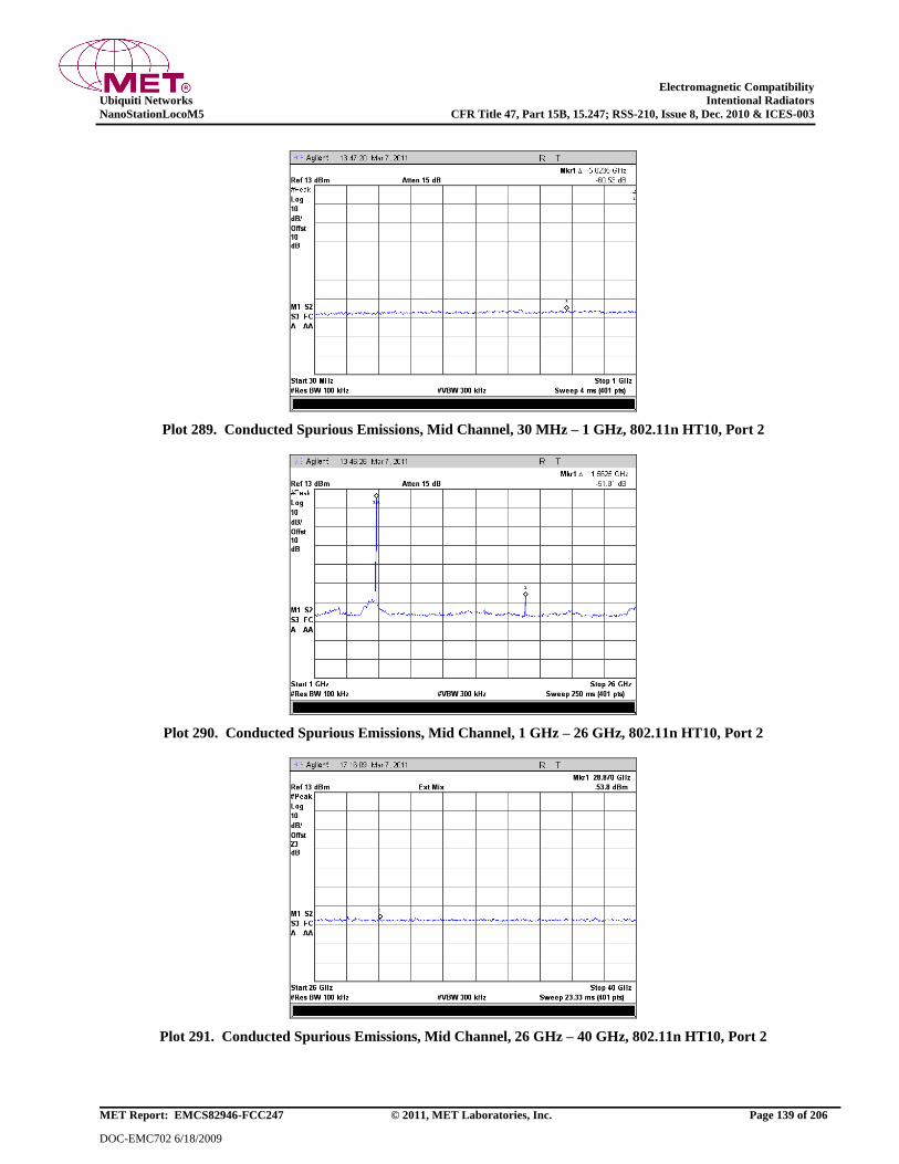
Electromagnetic Compatibility
Ubiquiti Networks Intentional Radiators
NanoStationLocoM5 CFR Title 47, Part 15B, 15.247; RSS-210, Issue 8, Dec. 2010 & ICES-003
MET Report: EMCS82946-FCC247 © 2011, MET Laboratories, Inc. Page 139 of 206
DOC-EMC702 6/18/2009
Plot 289. Conducted Spurious Emissions, Mid Channel, 30 MHz – 1 GHz, 802.11n HT10, Port 2
Plot 290. Conducted Spurious Emissions, Mid Channel, 1 GHz – 26 GHz, 802.11n HT10, Port 2
Plot 291. Conducted Spurious Emissions, Mid Channel, 26 GHz – 40 GHz, 802.11n HT10, Port 2

Electromagnetic Compatibility
Ubiquiti Networks Intentional Radiators
NanoStationLocoM5 CFR Title 47, Part 15B, 15.247; RSS-210, Issue 8, Dec. 2010 & ICES-003
MET Report: EMCS82946-FCC247 © 2011, MET Laboratories, Inc. Page 140 of 206
DOC-EMC702 6/18/2009
Plot 292. Conducted Spurious Emissions, High Channel, 30 MHz – 1 GHz, 802.11n HT10, Port 2
Plot 293. Conducted Spurious Emissions, High Channel, 1 GHz – 26 GHz, 802.11n HT10, Port 2
Plot 294. Conducted Spurious Emissions, High Channel, 26 GHz – 40 GHz, 802.11n HT10, Port 2

Electromagnetic Compatibility
Ubiquiti Networks Intentional Radiators
NanoStationLocoM5 CFR Title 47, Part 15B, 15.247; RSS-210, Issue 8, Dec. 2010 & ICES-003
MET Report: EMCS82946-FCC247 © 2011, MET Laboratories, Inc. Page 141 of 206
DOC-EMC702 6/18/2009
Conducted Spurious Emissions Test Results, 802.11n HT20, Port 1
Plot 295. Conducted Spurious Emissions, Low Channel, 30 MHz – 1 GHz, 802.11n HT20, Port 1
Plot 296. Conducted Spurious Emissions, Low Channel, 1 GHz – 26 GHz, 802.11n HT20, Port 1
Plot 297. Conducted Spurious Emissions, Low Channel, 26 GHz – 40 GHz, 802.11n HT20, Port 1
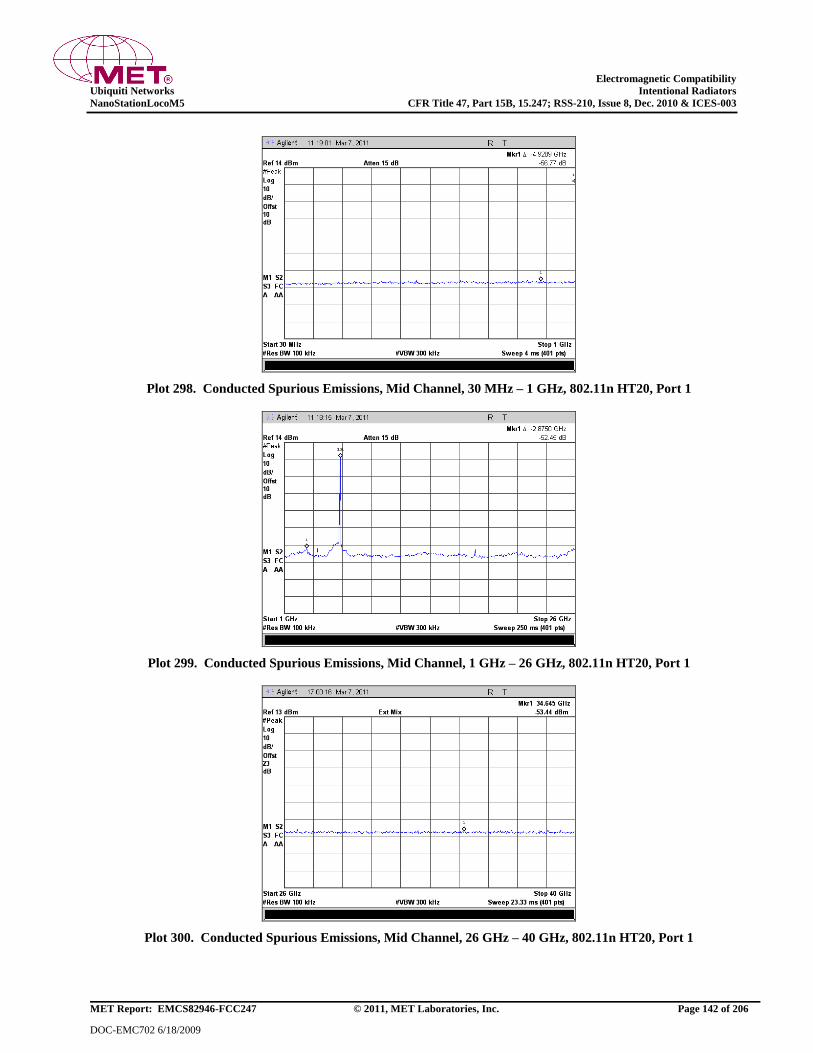
Electromagnetic Compatibility
Ubiquiti Networks Intentional Radiators
NanoStationLocoM5 CFR Title 47, Part 15B, 15.247; RSS-210, Issue 8, Dec. 2010 & ICES-003
MET Report: EMCS82946-FCC247 © 2011, MET Laboratories, Inc. Page 142 of 206
DOC-EMC702 6/18/2009
Plot 298. Conducted Spurious Emissions, Mid Channel, 30 MHz – 1 GHz, 802.11n HT20, Port 1
Plot 299. Conducted Spurious Emissions, Mid Channel, 1 GHz – 26 GHz, 802.11n HT20, Port 1
Plot 300. Conducted Spurious Emissions, Mid Channel, 26 GHz – 40 GHz, 802.11n HT20, Port 1

Electromagnetic Compatibility
Ubiquiti Networks Intentional Radiators
NanoStationLocoM5 CFR Title 47, Part 15B, 15.247; RSS-210, Issue 8, Dec. 2010 & ICES-003
MET Report: EMCS82946-FCC247 © 2011, MET Laboratories, Inc. Page 143 of 206
DOC-EMC702 6/18/2009
Plot 301. Conducted Spurious Emissions, High Channel, 30 MHz – 1 GHz, 802.11n HT20, Port 1
Plot 302. Conducted Spurious Emissions, High Channel, 1 GHz – 26 GHz, 802.11n HT20, Port 1
Plot 303. Conducted Spurious Emissions, High Channel, 26 GHz – 40 GHz, 802.11n HT20, Port 1
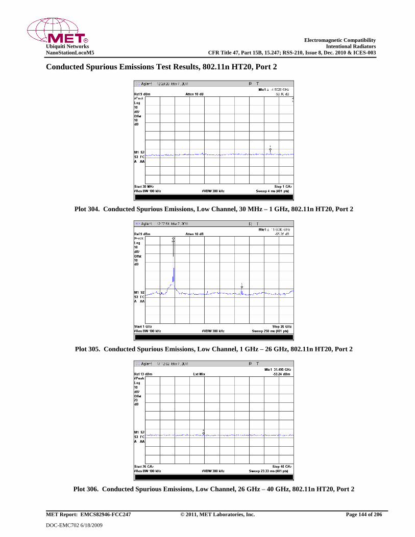
Electromagnetic Compatibility
Ubiquiti Networks Intentional Radiators
NanoStationLocoM5 CFR Title 47, Part 15B, 15.247; RSS-210, Issue 8, Dec. 2010 & ICES-003
MET Report: EMCS82946-FCC247 © 2011, MET Laboratories, Inc. Page 144 of 206
DOC-EMC702 6/18/2009
Conducted Spurious Emissions Test Results, 802.11n HT20, Port 2
Plot 304. Conducted Spurious Emissions, Low Channel, 30 MHz – 1 GHz, 802.11n HT20, Port 2
Plot 305. Conducted Spurious Emissions, Low Channel, 1 GHz – 26 GHz, 802.11n HT20, Port 2
Plot 306. Conducted Spurious Emissions, Low Channel, 26 GHz – 40 GHz, 802.11n HT20, Port 2

Electromagnetic Compatibility
Ubiquiti Networks Intentional Radiators
NanoStationLocoM5 CFR Title 47, Part 15B, 15.247; RSS-210, Issue 8, Dec. 2010 & ICES-003
MET Report: EMCS82946-FCC247 © 2011, MET Laboratories, Inc. Page 145 of 206
DOC-EMC702 6/18/2009
Plot 307. Conducted Spurious Emissions, Mid Channel, 30 MHz – 1 GHz, 802.11n HT20, Port 2
Plot 308. Conducted Spurious Emissions, Mid Channel, 1 GHz – 26 GHz, 802.11n HT20, Port 2
Plot 309. Conducted Spurious Emissions, Mid Channel, 26 GHz – 40 GHz, 802.11n HT20, Port 2

Electromagnetic Compatibility
Ubiquiti Networks Intentional Radiators
NanoStationLocoM5 CFR Title 47, Part 15B, 15.247; RSS-210, Issue 8, Dec. 2010 & ICES-003
MET Report: EMCS82946-FCC247 © 2011, MET Laboratories, Inc. Page 146 of 206
DOC-EMC702 6/18/2009
Plot 310. Conducted Spurious Emissions, High Channel, 30 MHz – 1 GHz, 802.11n HT20, Port 2
Plot 311. Conducted Spurious Emissions, High Channel, 1 GHz – 26 GHz, 802.11n HT20, Port 2
Plot 312. Conducted Spurious Emissions, High Channel, 26 GHz – 40 GHz, 802.11n HT20, Port 2

Electromagnetic Compatibility
Ubiquiti Networks Intentional Radiators
NanoStationLocoM5 CFR Title 47, Part 15B, 15.247; RSS-210, Issue 8, Dec. 2010 & ICES-003
MET Report: EMCS82946-FCC247 © 2011, MET Laboratories, Inc. Page 147 of 206
DOC-EMC702 6/18/2009
Conducted Spurious Emissions Test Results, 802.11n HT30, Port 1
Plot 313. Conducted Spurious Emissions, Low Channel, 30 MHz – 1 GHz, 802.11n HT30, Port 1
Plot 314. Conducted Spurious Emissions, Low Channel, 1 GHz – 26 GHz, 802.11n HT30, Port 1
Plot 315. Conducted Spurious Emissions, Low Channel, 26 GHz – 40 GHz, 802.11n HT30, Port 1
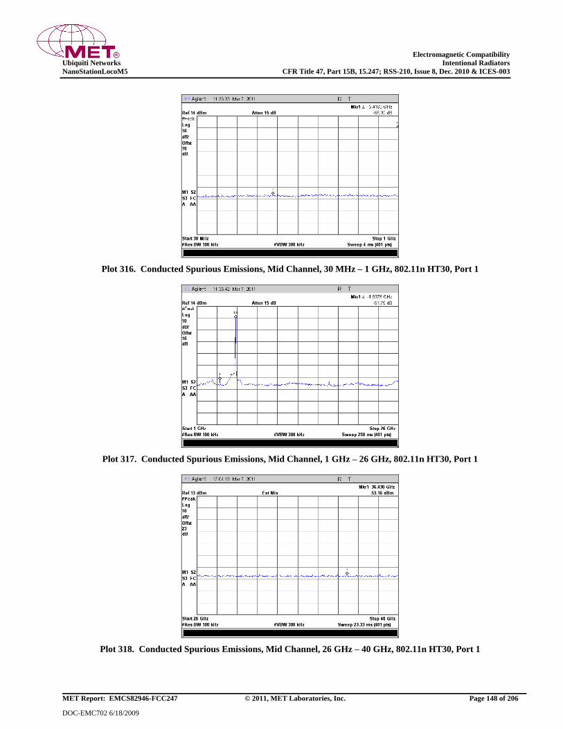
Electromagnetic Compatibility
Ubiquiti Networks Intentional Radiators
NanoStationLocoM5 CFR Title 47, Part 15B, 15.247; RSS-210, Issue 8, Dec. 2010 & ICES-003
MET Report: EMCS82946-FCC247 © 2011, MET Laboratories, Inc. Page 148 of 206
DOC-EMC702 6/18/2009
Plot 316. Conducted Spurious Emissions, Mid Channel, 30 MHz – 1 GHz, 802.11n HT30, Port 1
Plot 317. Conducted Spurious Emissions, Mid Channel, 1 GHz – 26 GHz, 802.11n HT30, Port 1
Plot 318. Conducted Spurious Emissions, Mid Channel, 26 GHz – 40 GHz, 802.11n HT30, Port 1
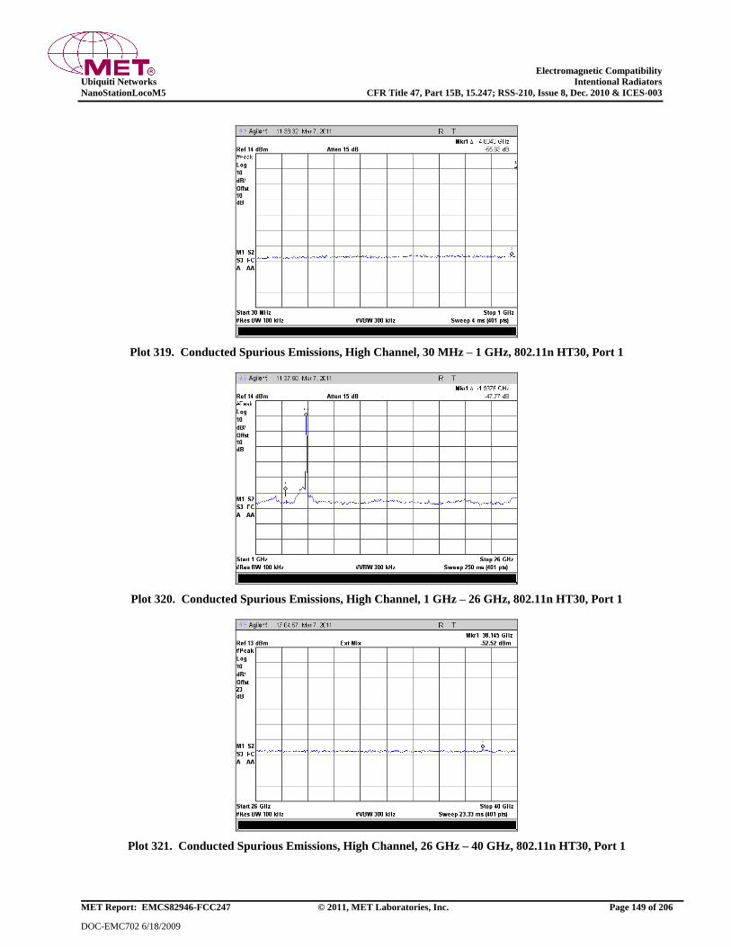
Electromagnetic Compatibility
Ubiquiti Networks Intentional Radiators
NanoStationLocoM5 CFR Title 47, Part 15B, 15.247; RSS-210, Issue 8, Dec. 2010 & ICES-003
MET Report: EMCS82946-FCC247 © 2011, MET Laboratories, Inc. Page 149 of 206
DOC-EMC702 6/18/2009
Plot 319. Conducted Spurious Emissions, High Channel, 30 MHz – 1 GHz, 802.11n HT30, Port 1
Plot 320. Conducted Spurious Emissions, High Channel, 1 GHz – 26 GHz, 802.11n HT30, Port 1
Plot 321. Conducted Spurious Emissions, High Channel, 26 GHz – 40 GHz, 802.11n HT30, Port 1
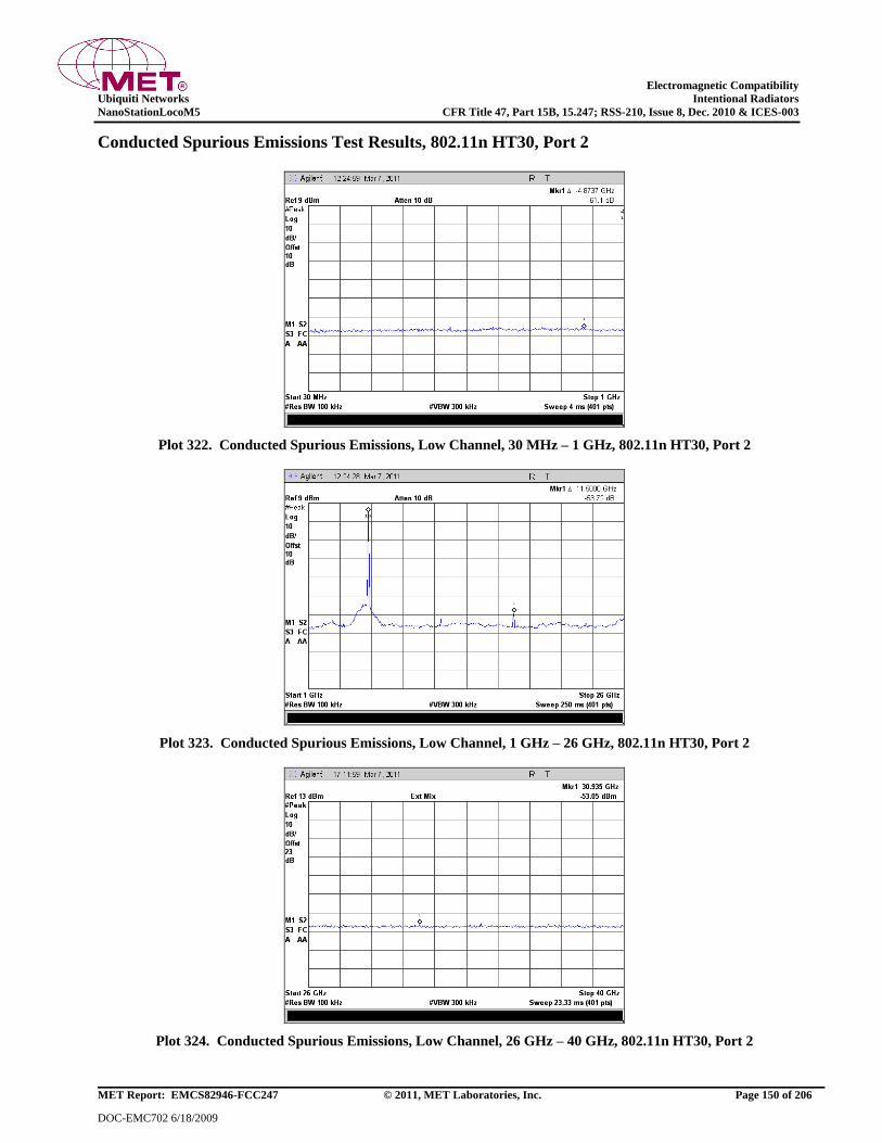
Electromagnetic Compatibility
Ubiquiti Networks Intentional Radiators
NanoStationLocoM5 CFR Title 47, Part 15B, 15.247; RSS-210, Issue 8, Dec. 2010 & ICES-003
MET Report: EMCS82946-FCC247 © 2011, MET Laboratories, Inc. Page 150 of 206
DOC-EMC702 6/18/2009
Conducted Spurious Emissions Test Results, 802.11n HT30, Port 2
Plot 322. Conducted Spurious Emissions, Low Channel, 30 MHz – 1 GHz, 802.11n HT30, Port 2
Plot 323. Conducted Spurious Emissions, Low Channel, 1 GHz – 26 GHz, 802.11n HT30, Port 2
Plot 324. Conducted Spurious Emissions, Low Channel, 26 GHz – 40 GHz, 802.11n HT30, Port 2
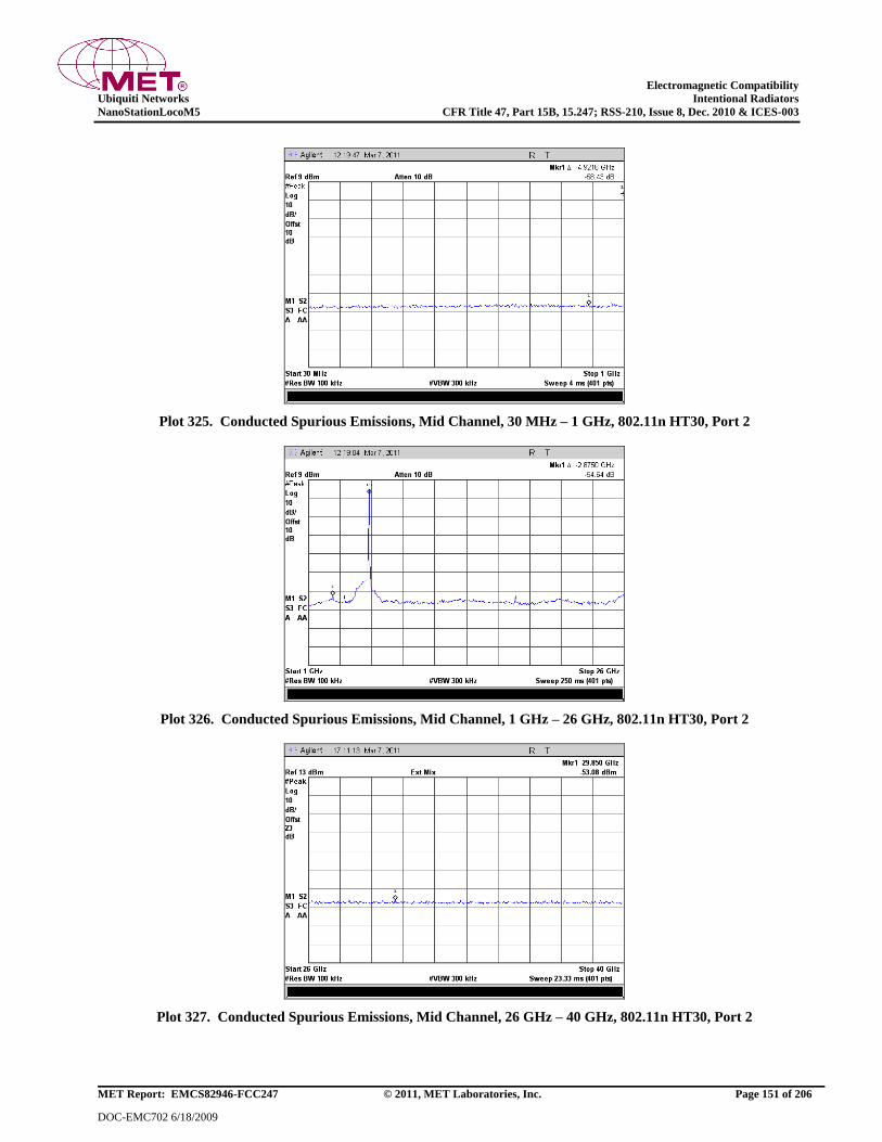
Electromagnetic Compatibility
Ubiquiti Networks Intentional Radiators
NanoStationLocoM5 CFR Title 47, Part 15B, 15.247; RSS-210, Issue 8, Dec. 2010 & ICES-003
MET Report: EMCS82946-FCC247 © 2011, MET Laboratories, Inc. Page 151 of 206
DOC-EMC702 6/18/2009
Plot 325. Conducted Spurious Emissions, Mid Channel, 30 MHz – 1 GHz, 802.11n HT30, Port 2
Plot 326. Conducted Spurious Emissions, Mid Channel, 1 GHz – 26 GHz, 802.11n HT30, Port 2
Plot 327. Conducted Spurious Emissions, Mid Channel, 26 GHz – 40 GHz, 802.11n HT30, Port 2
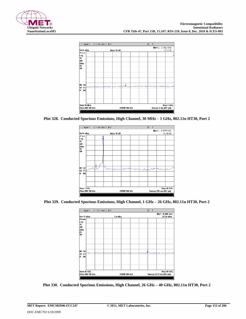
Electromagnetic Compatibility
Ubiquiti Networks Intentional Radiators
NanoStationLocoM5 CFR Title 47, Part 15B, 15.247; RSS-210, Issue 8, Dec. 2010 & ICES-003
MET Report: EMCS82946-FCC247 © 2011, MET Laboratories, Inc. Page 152 of 206
DOC-EMC702 6/18/2009
Plot 328. Conducted Spurious Emissions, High Channel, 30 MHz – 1 GHz, 802.11n HT30, Port 2
Plot 329. Conducted Spurious Emissions, High Channel, 1 GHz – 26 GHz, 802.11n HT30, Port 2
Plot 330. Conducted Spurious Emissions, High Channel, 26 GHz – 40 GHz, 802.11n HT30, Port 2
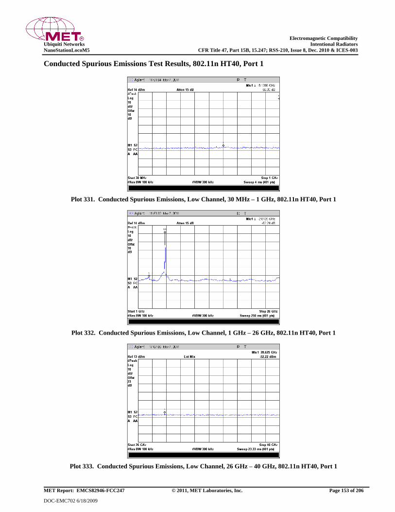
Electromagnetic Compatibility
Ubiquiti Networks Intentional Radiators
NanoStationLocoM5 CFR Title 47, Part 15B, 15.247; RSS-210, Issue 8, Dec. 2010 & ICES-003
MET Report: EMCS82946-FCC247 © 2011, MET Laboratories, Inc. Page 153 of 206
DOC-EMC702 6/18/2009
Conducted Spurious Emissions Test Results, 802.11n HT40, Port 1
Plot 331. Conducted Spurious Emissions, Low Channel, 30 MHz – 1 GHz, 802.11n HT40, Port 1
Plot 332. Conducted Spurious Emissions, Low Channel, 1 GHz – 26 GHz, 802.11n HT40, Port 1
Plot 333. Conducted Spurious Emissions, Low Channel, 26 GHz – 40 GHz, 802.11n HT40, Port 1

Electromagnetic Compatibility
Ubiquiti Networks Intentional Radiators
NanoStationLocoM5 CFR Title 47, Part 15B, 15.247; RSS-210, Issue 8, Dec. 2010 & ICES-003
MET Report: EMCS82946-FCC247 © 2011, MET Laboratories, Inc. Page 154 of 206
DOC-EMC702 6/18/2009
Plot 334. Conducted Spurious Emissions, Mid Channel, 30 MHz – 1 GHz, 802.11n HT40, Port 1
Plot 335. Conducted Spurious Emissions, Mid Channel, 1 GHz – 26 GHz, 802.11n HT40, Port 1
Plot 336. Conducted Spurious Emissions, Mid Channel, 26 GHz – 40 GHz, 802.11n HT40, Port 1
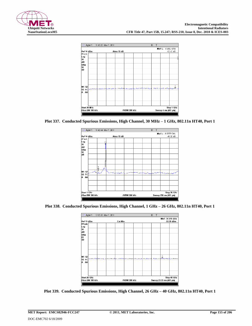
Electromagnetic Compatibility
Ubiquiti Networks Intentional Radiators
NanoStationLocoM5 CFR Title 47, Part 15B, 15.247; RSS-210, Issue 8, Dec. 2010 & ICES-003
MET Report: EMCS82946-FCC247 © 2011, MET Laboratories, Inc. Page 155 of 206
DOC-EMC702 6/18/2009
Plot 337. Conducted Spurious Emissions, High Channel, 30 MHz – 1 GHz, 802.11n HT40, Port 1
Plot 338. Conducted Spurious Emissions, High Channel, 1 GHz – 26 GHz, 802.11n HT40, Port 1
Plot 339. Conducted Spurious Emissions, High Channel, 26 GHz – 40 GHz, 802.11n HT40, Port 1

Electromagnetic Compatibility
Ubiquiti Networks Intentional Radiators
NanoStationLocoM5 CFR Title 47, Part 15B, 15.247; RSS-210, Issue 8, Dec. 2010 & ICES-003
MET Report: EMCS82946-FCC247 © 2011, MET Laboratories, Inc. Page 156 of 206
DOC-EMC702 6/18/2009
Conducted Spurious Emissions Test Results, 802.11n HT40, Port 2
Plot 340. Conducted Spurious Emissions, Low Channel, 30 MHz – 1 GHz, 802.11n HT40, Port 2
Plot 341. Conducted Spurious Emissions, Low Channel, 1 GHz – 26 GHz, 802.11n HT40, Port 2
Plot 342. Conducted Spurious Emissions, Low Channel, 26 GHz – 40 GHz, 802.11n HT40, Port 2
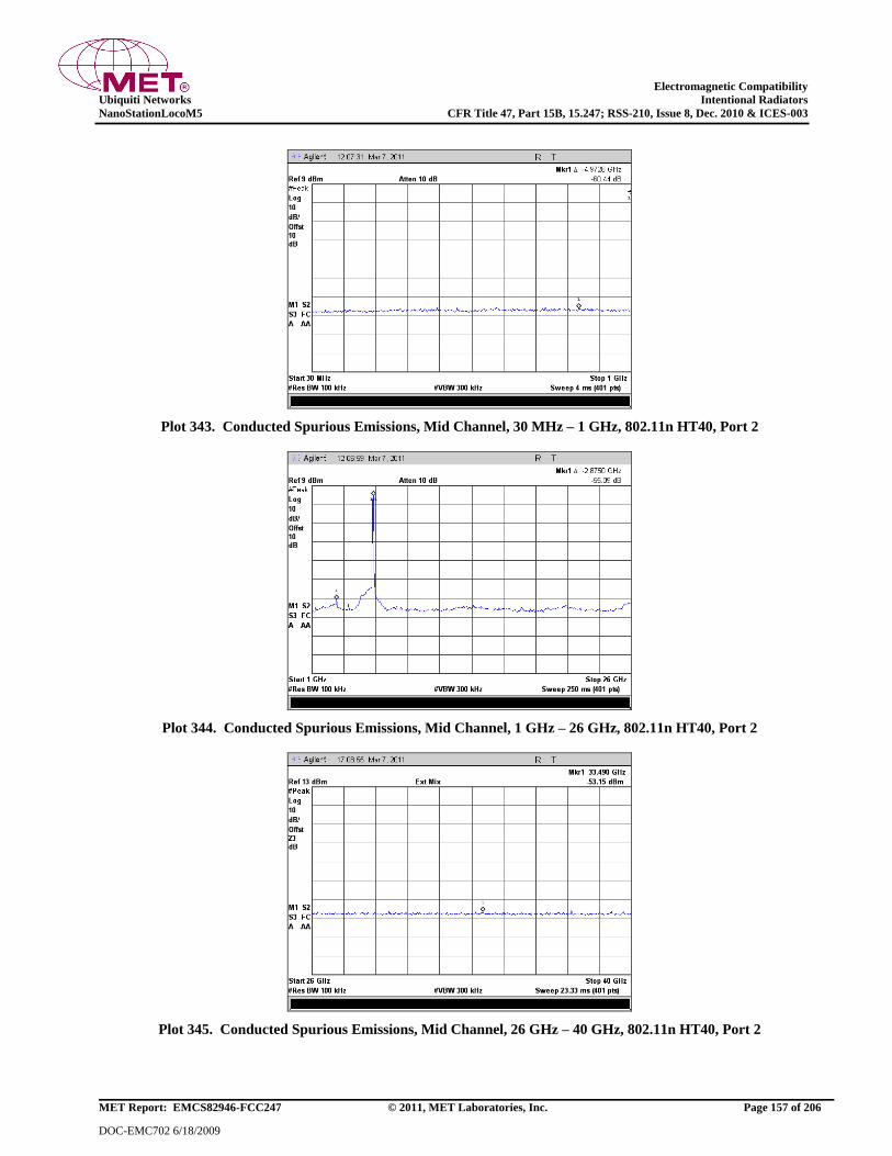
Electromagnetic Compatibility
Ubiquiti Networks Intentional Radiators
NanoStationLocoM5 CFR Title 47, Part 15B, 15.247; RSS-210, Issue 8, Dec. 2010 & ICES-003
MET Report: EMCS82946-FCC247 © 2011, MET Laboratories, Inc. Page 157 of 206
DOC-EMC702 6/18/2009
Plot 343. Conducted Spurious Emissions, Mid Channel, 30 MHz – 1 GHz, 802.11n HT40, Port 2
Plot 344. Conducted Spurious Emissions, Mid Channel, 1 GHz – 26 GHz, 802.11n HT40, Port 2
Plot 345. Conducted Spurious Emissions, Mid Channel, 26 GHz – 40 GHz, 802.11n HT40, Port 2
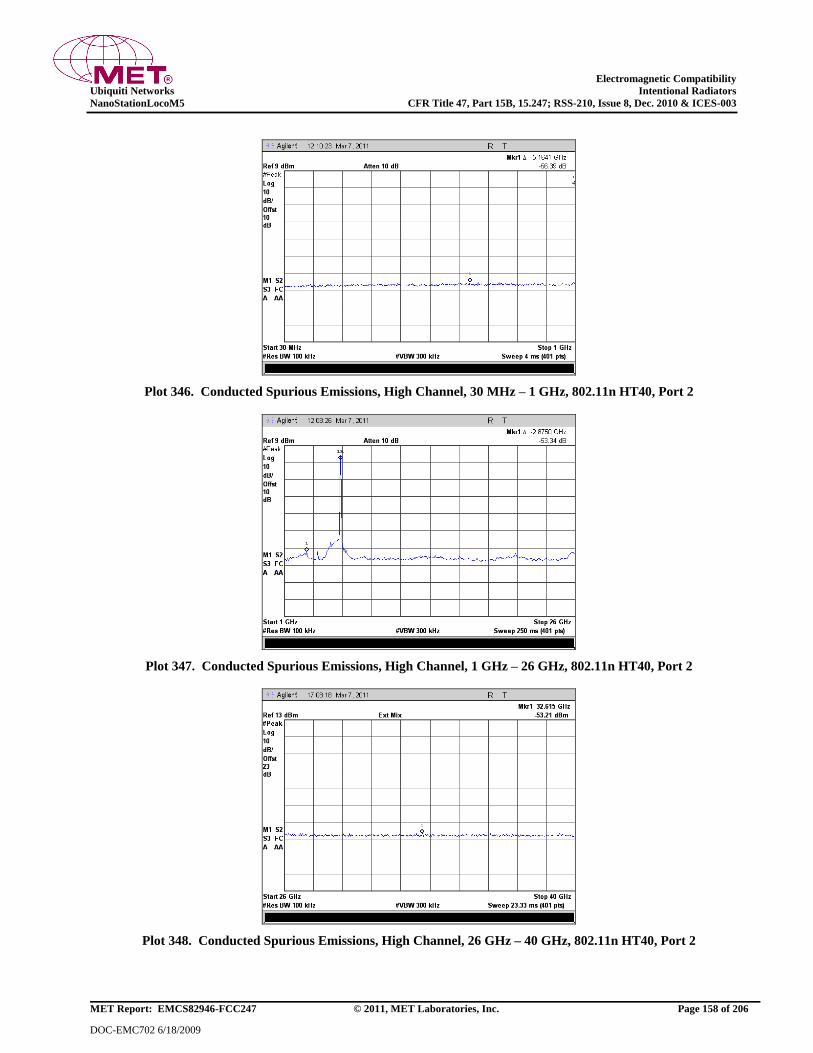
Electromagnetic Compatibility
Ubiquiti Networks Intentional Radiators
NanoStationLocoM5 CFR Title 47, Part 15B, 15.247; RSS-210, Issue 8, Dec. 2010 & ICES-003
MET Report: EMCS82946-FCC247 © 2011, MET Laboratories, Inc. Page 158 of 206
DOC-EMC702 6/18/2009
Plot 346. Conducted Spurious Emissions, High Channel, 30 MHz – 1 GHz, 802.11n HT40, Port 2
Plot 347. Conducted Spurious Emissions, High Channel, 1 GHz – 26 GHz, 802.11n HT40, Port 2
Plot 348. Conducted Spurious Emissions, High Channel, 26 GHz – 40 GHz, 802.11n HT40, Port 2
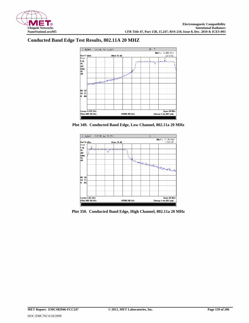
Electromagnetic Compatibility
Ubiquiti Networks Intentional Radiators
NanoStationLocoM5 CFR Title 47, Part 15B, 15.247; RSS-210, Issue 8, Dec. 2010 & ICES-003
MET Report: EMCS82946-FCC247 © 2011, MET Laboratories, Inc. Page 159 of 206
DOC-EMC702 6/18/2009
Conducted Band Edge Test Results, 802.11A 20 MHZ
Plot 349. Conducted Band Edge, Low Channel, 802.11a 20 MHz
Plot 350. Conducted Band Edge, High Channel, 802.11a 20 MHz

Electromagnetic Compatibility
Ubiquiti Networks Intentional Radiators
NanoStationLocoM5 CFR Title 47, Part 15B, 15.247; RSS-210, Issue 8, Dec. 2010 & ICES-003
MET Report: EMCS82946-FCC247 © 2011, MET Laboratories, Inc. Page 160 of 206
DOC-EMC702 6/18/2009
Conducted Band Edge Test Results, 802.11A 40 MHZ
Plot 351. Conducted Band Edge, Low Channel, 802.11a 40 MHz
Plot 352. Conducted Band Edge, High Channel, 802.11a 40 MHz

Electromagnetic Compatibility
Ubiquiti Networks Intentional Radiators
NanoStationLocoM5 CFR Title 47, Part 15B, 15.247; RSS-210, Issue 8, Dec. 2010 & ICES-003
MET Report: EMCS82946-FCC247 © 2011, MET Laboratories, Inc. Page 161 of 206
DOC-EMC702 6/18/2009
Conducted Band Edge Test Results, 802.11n HT5, Port 1
Plot 353. Conducted Band Edge, Low Channel, 802.11n HT5, Port 1
Plot 354. Conducted Band Edge, High Channel, 802.11n HT5, Port 1

Electromagnetic Compatibility
Ubiquiti Networks Intentional Radiators
NanoStationLocoM5 CFR Title 47, Part 15B, 15.247; RSS-210, Issue 8, Dec. 2010 & ICES-003
MET Report: EMCS82946-FCC247 © 2011, MET Laboratories, Inc. Page 162 of 206
DOC-EMC702 6/18/2009
Conducted Band Edge Test Results, 802.11n HT5, Port 2
Plot 355. Conducted Band Edge, Low Channel, 802.11n HT5, Port 2
Plot 356. Conducted Band Edge, High Channel, 802.11n HT5, Port 2

Electromagnetic Compatibility
Ubiquiti Networks Intentional Radiators
NanoStationLocoM5 CFR Title 47, Part 15B, 15.247; RSS-210, Issue 8, Dec. 2010 & ICES-003
MET Report: EMCS82946-FCC247 © 2011, MET Laboratories, Inc. Page 163 of 206
DOC-EMC702 6/18/2009
Conducted Band Edge Test Results, 802.11n HT8, Port 1
Plot 357. Conducted Band Edge, Low Channel, 802.11n HT8, Port 1
Plot 358. Conducted Band Edge, High Channel, 802.11n HT8, Port 1

Electromagnetic Compatibility
Ubiquiti Networks Intentional Radiators
NanoStationLocoM5 CFR Title 47, Part 15B, 15.247; RSS-210, Issue 8, Dec. 2010 & ICES-003
MET Report: EMCS82946-FCC247 © 2011, MET Laboratories, Inc. Page 164 of 206
DOC-EMC702 6/18/2009
Conducted Band Edge Test Results, 802.11n HT8, Port 2
Plot 359. Conducted Band Edge, Low Channel, 802.11n HT8, Port 2
Plot 360. Conducted Band Edge, High Channel, 802.11n HT8, Port 2

Electromagnetic Compatibility
Ubiquiti Networks Intentional Radiators
NanoStationLocoM5 CFR Title 47, Part 15B, 15.247; RSS-210, Issue 8, Dec. 2010 & ICES-003
MET Report: EMCS82946-FCC247 © 2011, MET Laboratories, Inc. Page 165 of 206
DOC-EMC702 6/18/2009
Conducted Band Edge Test Results, 802.11n HT10, Port 1
Plot 361. Conducted Band Edge, Low Channel, 802.11n HT10, Port 1
Plot 362. Conducted Band Edge, High Channel, 802.11n HT10, Port 1
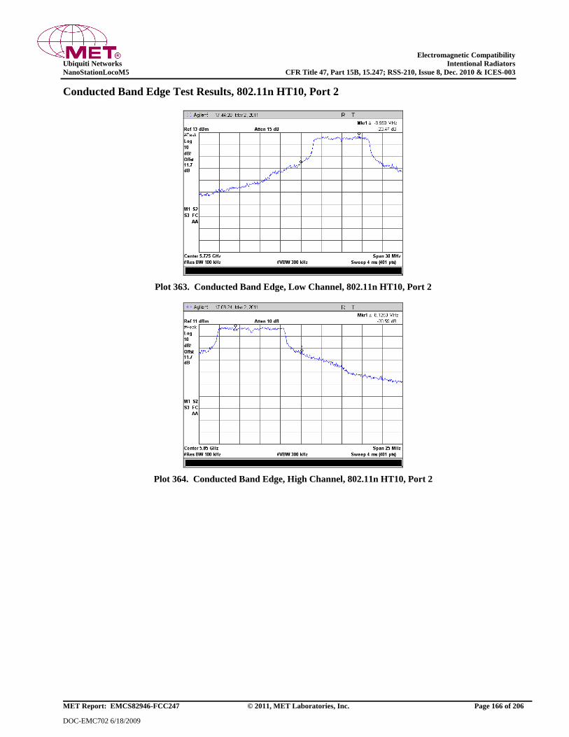
Electromagnetic Compatibility
Ubiquiti Networks Intentional Radiators
NanoStationLocoM5 CFR Title 47, Part 15B, 15.247; RSS-210, Issue 8, Dec. 2010 & ICES-003
MET Report: EMCS82946-FCC247 © 2011, MET Laboratories, Inc. Page 166 of 206
DOC-EMC702 6/18/2009
Conducted Band Edge Test Results, 802.11n HT10, Port 2
Plot 363. Conducted Band Edge, Low Channel, 802.11n HT10, Port 2
Plot 364. Conducted Band Edge, High Channel, 802.11n HT10, Port 2

Electromagnetic Compatibility
Ubiquiti Networks Intentional Radiators
NanoStationLocoM5 CFR Title 47, Part 15B, 15.247; RSS-210, Issue 8, Dec. 2010 & ICES-003
MET Report: EMCS82946-FCC247 © 2011, MET Laboratories, Inc. Page 167 of 206
DOC-EMC702 6/18/2009
Conducted Band Edge Test Results, 802.11n HT20, Port 1
Plot 365. Conducted Band Edge, Low Channel, 802.11n HT20, Port 1
Plot 366. Conducted Band Edge, High Channel, 802.11n HT20, Port 1

Electromagnetic Compatibility
Ubiquiti Networks Intentional Radiators
NanoStationLocoM5 CFR Title 47, Part 15B, 15.247; RSS-210, Issue 8, Dec. 2010 & ICES-003
MET Report: EMCS82946-FCC247 © 2011, MET Laboratories, Inc. Page 168 of 206
DOC-EMC702 6/18/2009
Conducted Band Edge Test Results, 802.11n HT20, Port 2
Plot 367. Conducted Band Edge, Low Channel, 802.11n HT20, Port 2
Plot 368. Conducted Band Edge, High Channel, 802.11n HT20, Port 2
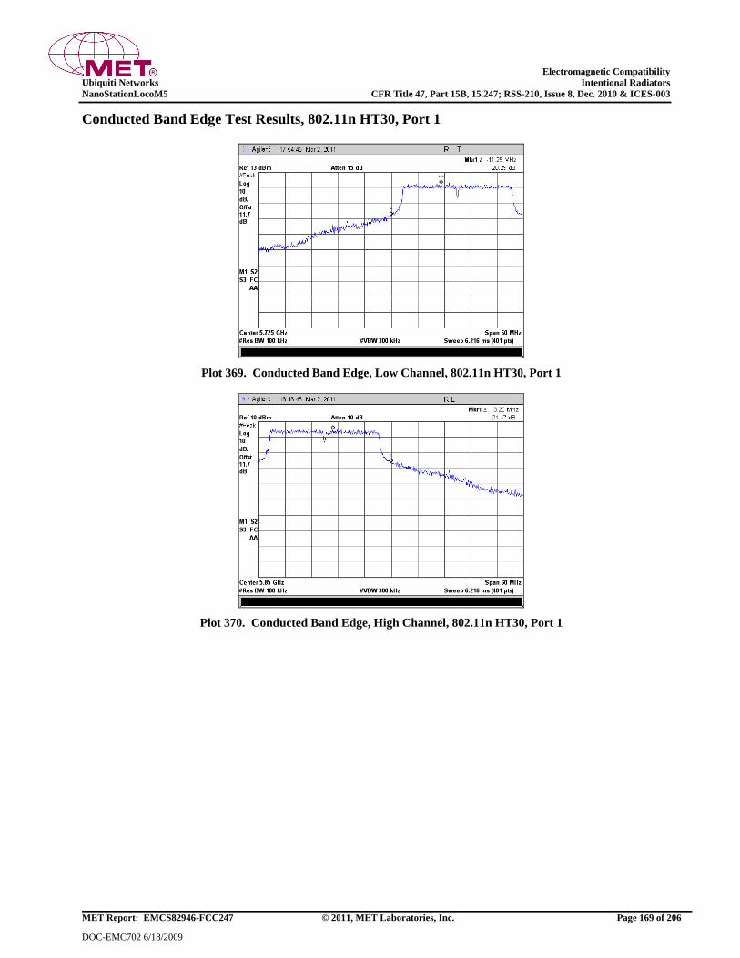
Electromagnetic Compatibility
Ubiquiti Networks Intentional Radiators
NanoStationLocoM5 CFR Title 47, Part 15B, 15.247; RSS-210, Issue 8, Dec. 2010 & ICES-003
MET Report: EMCS82946-FCC247 © 2011, MET Laboratories, Inc. Page 169 of 206
DOC-EMC702 6/18/2009
Conducted Band Edge Test Results, 802.11n HT30, Port 1
Plot 369. Conducted Band Edge, Low Channel, 802.11n HT30, Port 1
Plot 370. Conducted Band Edge, High Channel, 802.11n HT30, Port 1

Electromagnetic Compatibility
Ubiquiti Networks Intentional Radiators
NanoStationLocoM5 CFR Title 47, Part 15B, 15.247; RSS-210, Issue 8, Dec. 2010 & ICES-003
MET Report: EMCS82946-FCC247 © 2011, MET Laboratories, Inc. Page 170 of 206
DOC-EMC702 6/18/2009
Conducted Band Edge Test Results, 802.11n HT30, Port 2
Plot 371. Conducted Band Edge, Low Channel, 802.11n HT30, Port 2
Plot 372. Conducted Band Edge, High Channel, 802.11n HT30, Port 2

Electromagnetic Compatibility
Ubiquiti Networks Intentional Radiators
NanoStationLocoM5 CFR Title 47, Part 15B, 15.247; RSS-210, Issue 8, Dec. 2010 & ICES-003
MET Report: EMCS82946-FCC247 © 2011, MET Laboratories, Inc. Page 171 of 206
DOC-EMC702 6/18/2009
Conducted Band Edge Test Results, 802.11n HT40, Port 1
Plot 373. Conducted Band Edge, Low Channel, 802.11n HT40, Port 1
Plot 374. Conducted Band Edge, High Channel, 802.11n HT40, Port 1

Electromagnetic Compatibility
Ubiquiti Networks Intentional Radiators
NanoStationLocoM5 CFR Title 47, Part 15B, 15.247; RSS-210, Issue 8, Dec. 2010 & ICES-003
MET Report: EMCS82946-FCC247 © 2011, MET Laboratories, Inc. Page 172 of 206
DOC-EMC702 6/18/2009
Conducted Band Edge Test Results, 802.11n HT40, Port 2
Plot 375. Conducted Band Edge, Low Channel, 802.11n HT40, Port 2
Plot 376. Conducted Band Edge, High Channel, 802.11n HT40, Port 2
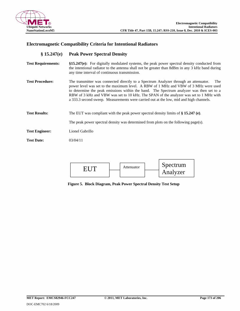
Electromagnetic Compatibility
Ubiquiti Networks Intentional Radiators
NanoStationLocoM5 CFR Title 47, Part 15B, 15.247; RSS-210, Issue 8, Dec. 2010 & ICES-003
MET Report: EMCS82946-FCC247 © 2011, MET Laboratories, Inc. Page 173 of 206
DOC-EMC702 6/18/2009
Electromagnetic Compatibility Criteria for Intentional Radiators
§ 15.247(e) Peak Power Spectral Density
Test Requirements: §15.247(e): For digitally modulated systems, the peak power spectral density conducted from
the intentional radiator to the antenna shall not be greater than 8dBm in any 3 kHz band during
any time interval of continuous transmission.
Test Procedure: The transmitter was connected directly to a Spectrum Analyzer through an attenuator. The
power level was set to the maximum level. A RBW of 1 MHz and VBW of 3 MHz were used
to determine the peak emissions within the band. The Spectrum analyzer was then set to a
RBW of 3 kHz and VBW was set to 10 kHz. The SPAN of the analyzer was set to 1 MHz with
a 333.3 second sweep. Measurements were carried out at the low, mid and high channels.
Test Results: The EUT was compliant with the peak power spectral density limits of § 15.247 (e).
The peak power spectral density was determined from plots on the following page(s).
Test Engineer: Lionel Gabrillo
Test Date: 03/04/11
Figure 5. Block Diagram, Peak Power Spectral Density Test Setup
EUT Attenuator Spectrum
Analyzer
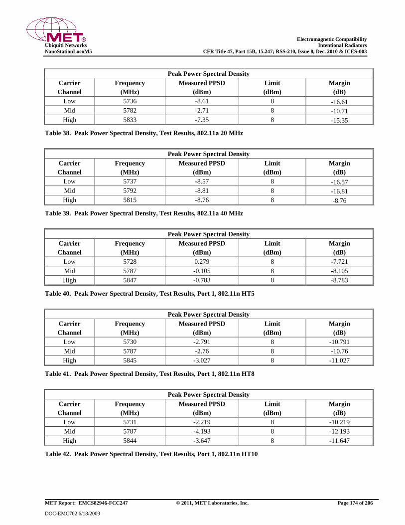
Electromagnetic Compatibility
Ubiquiti Networks Intentional Radiators
NanoStationLocoM5 CFR Title 47, Part 15B, 15.247; RSS-210, Issue 8, Dec. 2010 & ICES-003
MET Report: EMCS82946-FCC247 © 2011, MET Laboratories, Inc. Page 174 of 206
DOC-EMC702 6/18/2009
Peak Power Spectral Density
Carrier
Channel
Frequency
(MHz)
Measured PPSD
(dBm)
Limit
(dBm)
Margin
(dB)
Low 5736 -8.61 8 -16.61
Mid 5782 -2.71 8 -10.71
High 5833 -7.35 8 -15.35
Table 38. Peak Power Spectral Density, Test Results, 802.11a 20 MHz
Peak Power Spectral Density
Carrier
Channel
Frequency
(MHz)
Measured PPSD
(dBm)
Limit
(dBm)
Margin
(dB)
Low 5737 -8.57 8 -16.57
Mid 5792 -8.81 8 -16.81
High 5815 -8.76 8 -8.76
Table 39. Peak Power Spectral Density, Test Results, 802.11a 40 MHz
Peak Power Spectral Density
Carrier
Channel
Frequency
(MHz)
Measured PPSD
(dBm)
Limit
(dBm)
Margin
(dB)
Low 5728 0.279 8 -7.721
Mid 5787 -0.105 8 -8.105
High 5847 -0.783 8 -8.783
Table 40. Peak Power Spectral Density, Test Results, Port 1, 802.11n HT5
Peak Power Spectral Density
Carrier
Channel
Frequency
(MHz)
Measured PPSD
(dBm)
Limit
(dBm)
Margin
(dB)
Low 5730 -2.791 8 -10.791
Mid 5787 -2.76 8 -10.76
High 5845 -3.027 8 -11.027
Table 41. Peak Power Spectral Density, Test Results, Port 1, 802.11n HT8
Peak Power Spectral Density
Carrier
Channel
Frequency
(MHz)
Measured PPSD
(dBm)
Limit
(dBm)
Margin
(dB)
Low 5731 -2.219 8 -10.219
Mid 5787 -4.193 8 -12.193
High 5844 -3.647 8 -11.647
Table 42. Peak Power Spectral Density, Test Results, Port 1, 802.11n HT10
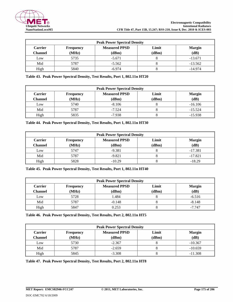
Electromagnetic Compatibility
Ubiquiti Networks Intentional Radiators
NanoStationLocoM5 CFR Title 47, Part 15B, 15.247; RSS-210, Issue 8, Dec. 2010 & ICES-003
MET Report: EMCS82946-FCC247 © 2011, MET Laboratories, Inc. Page 175 of 206
DOC-EMC702 6/18/2009
Peak Power Spectral Density
Carrier
Channel
Frequency
(MHz)
Measured PPSD
(dBm)
Limit
(dBm)
Margin
(dB)
Low 5735 -5.671 8 -13.671
Mid 5787 -5.562 8 -13.562
High 5840 -6.974 8 -14.974
Table 43. Peak Power Spectral Density, Test Results, Port 1, 802.11n HT20
Peak Power Spectral Density
Carrier
Channel
Frequency
(MHz)
Measured PPSD
(dBm)
Limit
(dBm)
Margin
(dB)
Low 5740 -8.106 8 -16.106
Mid 5787 -7.524 8 -15.524
High 5835 -7.938 8 -15.938
Table 44. Peak Power Spectral Density, Test Results, Port 1, 802.11n HT30
Peak Power Spectral Density
Carrier
Channel
Frequency
(MHz)
Measured PPSD
(dBm)
Limit
(dBm)
Margin
(dB)
Low 5747 -9.381 8 -17.381
Mid 5787 -9.821 8 -17.821
High 5828 -10.29 8 -18.29
Table 45. Peak Power Spectral Density, Test Results, Port 1, 802.11n HT40
Peak Power Spectral Density
Carrier
Channel
Frequency
(MHz)
Measured PPSD
(dBm)
Limit
(dBm)
Margin
(dB)
Low 5728 1.484 8 -6.516
Mid 5787 -0.148 8 -8.148
High 5847 0.253 8 -7.747
Table 46. Peak Power Spectral Density, Test Results, Port 2, 802.11n HT5
Peak Power Spectral Density
Carrier
Channel
Frequency
(MHz)
Measured PPSD
(dBm)
Limit
(dBm)
Margin
(dB)
Low 5730 -2.367 8 -10.367
Mid 5787 -2.659 8 -10.659
High 5845 -3.308 8 -11.308
Table 47. Peak Power Spectral Density, Test Results, Port 2, 802.11n HT8
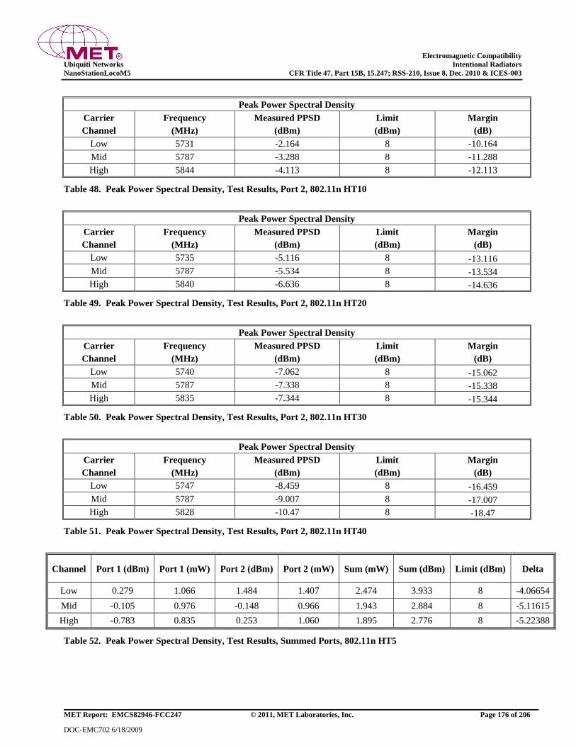
Electromagnetic Compatibility
Ubiquiti Networks Intentional Radiators
NanoStationLocoM5 CFR Title 47, Part 15B, 15.247; RSS-210, Issue 8, Dec. 2010 & ICES-003
MET Report: EMCS82946-FCC247 © 2011, MET Laboratories, Inc. Page 176 of 206
DOC-EMC702 6/18/2009
Peak Power Spectral Density
Carrier
Channel
Frequency
(MHz)
Measured PPSD
(dBm)
Limit
(dBm)
Margin
(dB)
Low 5731 -2.164 8 -10.164
Mid 5787 -3.288 8 -11.288
High 5844 -4.113 8 -12.113
Table 48. Peak Power Spectral Density, Test Results, Port 2, 802.11n HT10
Peak Power Spectral Density
Carrier
Channel
Frequency
(MHz)
Measured PPSD
(dBm)
Limit
(dBm)
Margin
(dB)
Low 5735 -5.116 8 -13.116
Mid 5787 -5.534 8 -13.534
High 5840 -6.636 8 -14.636
Table 49. Peak Power Spectral Density, Test Results, Port 2, 802.11n HT20
Peak Power Spectral Density
Carrier
Channel
Frequency
(MHz)
Measured PPSD
(dBm)
Limit
(dBm)
Margin
(dB)
Low 5740 -7.062 8 -15.062
Mid 5787 -7.338 8 -15.338
High 5835 -7.344 8 -15.344
Table 50. Peak Power Spectral Density, Test Results, Port 2, 802.11n HT30
Peak Power Spectral Density
Carrier
Channel
Frequency
(MHz)
Measured PPSD
(dBm)
Limit
(dBm)
Margin
(dB)
Low 5747 -8.459 8 -16.459
Mid 5787 -9.007 8 -17.007
High 5828 -10.47 8 -18.47
Table 51. Peak Power Spectral Density, Test Results, Port 2, 802.11n HT40
Channel Port 1 (dBm) Port 1 (mW) Port 2 (dBm) Port 2 (mW) Sum (mW) Sum (dBm) Limit (dBm) Delta
Low 0.279 1.066 1.484 1.407 2.474 3.933 8 -4.06654
Mid -0.105 0.976 -0.148 0.966 1.943 2.884 8 -5.11615
High -0.783 0.835 0.253 1.060 1.895 2.776 8 -5.22388
Table 52. Peak Power Spectral Density, Test Results, Summed Ports, 802.11n HT5
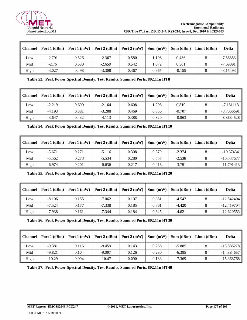
Electromagnetic Compatibility
Ubiquiti Networks Intentional Radiators
NanoStationLocoM5 CFR Title 47, Part 15B, 15.247; RSS-210, Issue 8, Dec. 2010 & ICES-003
MET Report: EMCS82946-FCC247 © 2011, MET Laboratories, Inc. Page 177 of 206
DOC-EMC702 6/18/2009
Channel Port 1 (dBm) Port 1 (mW) Port 2 (dBm) Port 2 (mW) Sum (mW) Sum (dBm) Limit (dBm) Delta
Low -2.791 0.526 -2.367 0.580 1.106 0.436 8 -7.56353
Mid -2.76 0.530 -2.659 0.542 1.072 0.301 8 -7.69891
High -3.027 0.498 -3.308 0.467 0.965 -0.155 8 -8.15493
Table 53. Peak Power Spectral Density, Test Results, Summed Ports, 802.11n HT8
Channel Port 1 (dBm) Port 1 (mW) Port 2 (dBm) Port 2 (mW) Sum (mW) Sum (dBm) Limit (dBm) Delta
Low -2.219 0.600 -2.164 0.608 1.208 0.819 8 -7.181113
Mid -4.193 0.381 -3.288 0.469 0.850 -0.707 8 -8.7066691
High -3.647 0.432 -4.113 0.388 0.820 -0.863 8 -8.8634528
Table 54. Peak Power Spectral Density, Test Results, Summed Ports, 802.11n HT10
Channel Port 1 (dBm) Port 1 (mW) Port 2 (dBm) Port 2 (mW) Sum (mW) Sum (dBm) Limit (dBm) Delta
Low -5.671 0.271 -5.116 0.308 0.579 -2.374 8 -10.37434
Mid -5.562 0.278 -5.534 0.280 0.557 -2.538 8 -10.537677
High -6.974 0.201 -6.636 0.217 0.418 -3.791 8 -11.791413
Table 55. Peak Power Spectral Density, Test Results, Summed Ports, 802.11n HT20
Channel Port 1 (dBm) Port 1 (mW) Port 2 (dBm) Port 2 (mW) Sum (mW) Sum (dBm) Limit (dBm) Delta
Low -8.106 0.155 -7.062 0.197 0.351 -4.542 8 -12.542404
Mid -7.524 0.177 -7.338 0.185 0.361 -4.420 8 -12.419704
High -7.938 0.161 -7.344 0.184 0.345 -4.621 8 -12.620553
Table 56. Peak Power Spectral Density, Test Results, Summed Ports, 802.11n HT30
Channel Port 1 (dBm) Port 1 (mW) Port 2 (dBm) Port 2 (mW) Sum (mW) Sum (dBm) Limit (dBm) Delta
Low -9.381 0.115 -8.459 0.143 0.258 -5.885 8 -13.885278
Mid -9.821 0.104 -9.007 0.126 0.230 -6.385 8 -14.384657
High -10.29 0.094 -10.47 0.090 0.183 -7.369 8 -15.368768
Table 57. Peak Power Spectral Density, Test Results, Summed Ports, 802.11n HT40
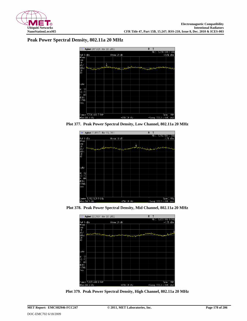
Electromagnetic Compatibility
Ubiquiti Networks Intentional Radiators
NanoStationLocoM5 CFR Title 47, Part 15B, 15.247; RSS-210, Issue 8, Dec. 2010 & ICES-003
MET Report: EMCS82946-FCC247 © 2011, MET Laboratories, Inc. Page 178 of 206
DOC-EMC702 6/18/2009
Peak Power Spectral Density, 802.11a 20 MHz
Plot 377. Peak Power Spectral Density, Low Channel, 802.11a 20 MHz
Plot 378. Peak Power Spectral Density, Mid Channel, 802.11a 20 MHz
Plot 379. Peak Power Spectral Density, High Channel, 802.11a 20 MHz
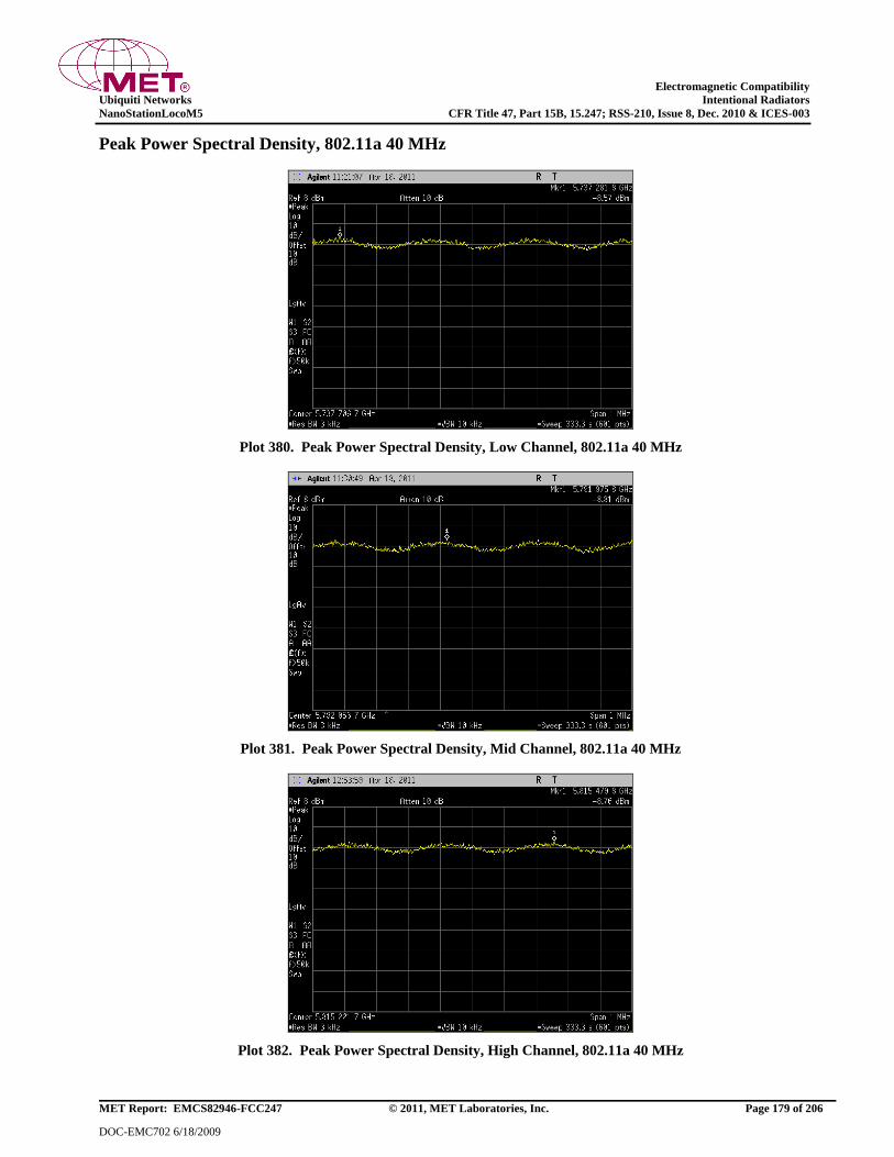
Electromagnetic Compatibility
Ubiquiti Networks Intentional Radiators
NanoStationLocoM5 CFR Title 47, Part 15B, 15.247; RSS-210, Issue 8, Dec. 2010 & ICES-003
MET Report: EMCS82946-FCC247 © 2011, MET Laboratories, Inc. Page 179 of 206
DOC-EMC702 6/18/2009
Peak Power Spectral Density, 802.11a 40 MHz
Plot 380. Peak Power Spectral Density, Low Channel, 802.11a 40 MHz
Plot 381. Peak Power Spectral Density, Mid Channel, 802.11a 40 MHz
Plot 382. Peak Power Spectral Density, High Channel, 802.11a 40 MHz
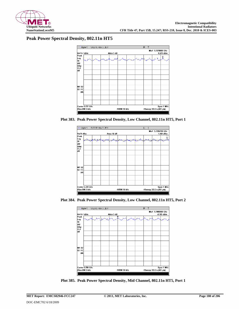
Electromagnetic Compatibility
Ubiquiti Networks Intentional Radiators
NanoStationLocoM5 CFR Title 47, Part 15B, 15.247; RSS-210, Issue 8, Dec. 2010 & ICES-003
MET Report: EMCS82946-FCC247 © 2011, MET Laboratories, Inc. Page 180 of 206
DOC-EMC702 6/18/2009
Peak Power Spectral Density, 802.11n HT5
Plot 383. Peak Power Spectral Density, Low Channel, 802.11n HT5, Port 1
Plot 384. Peak Power Spectral Density, Low Channel, 802.11n HT5, Port 2
Plot 385. Peak Power Spectral Density, Mid Channel, 802.11n HT5, Port 1
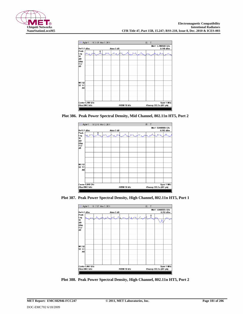
Electromagnetic Compatibility
Ubiquiti Networks Intentional Radiators
NanoStationLocoM5 CFR Title 47, Part 15B, 15.247; RSS-210, Issue 8, Dec. 2010 & ICES-003
MET Report: EMCS82946-FCC247 © 2011, MET Laboratories, Inc. Page 181 of 206
DOC-EMC702 6/18/2009
Plot 386. Peak Power Spectral Density, Mid Channel, 802.11n HT5, Port 2
Plot 387. Peak Power Spectral Density, High Channel, 802.11n HT5, Port 1
Plot 388. Peak Power Spectral Density, High Channel, 802.11n HT5, Port 2
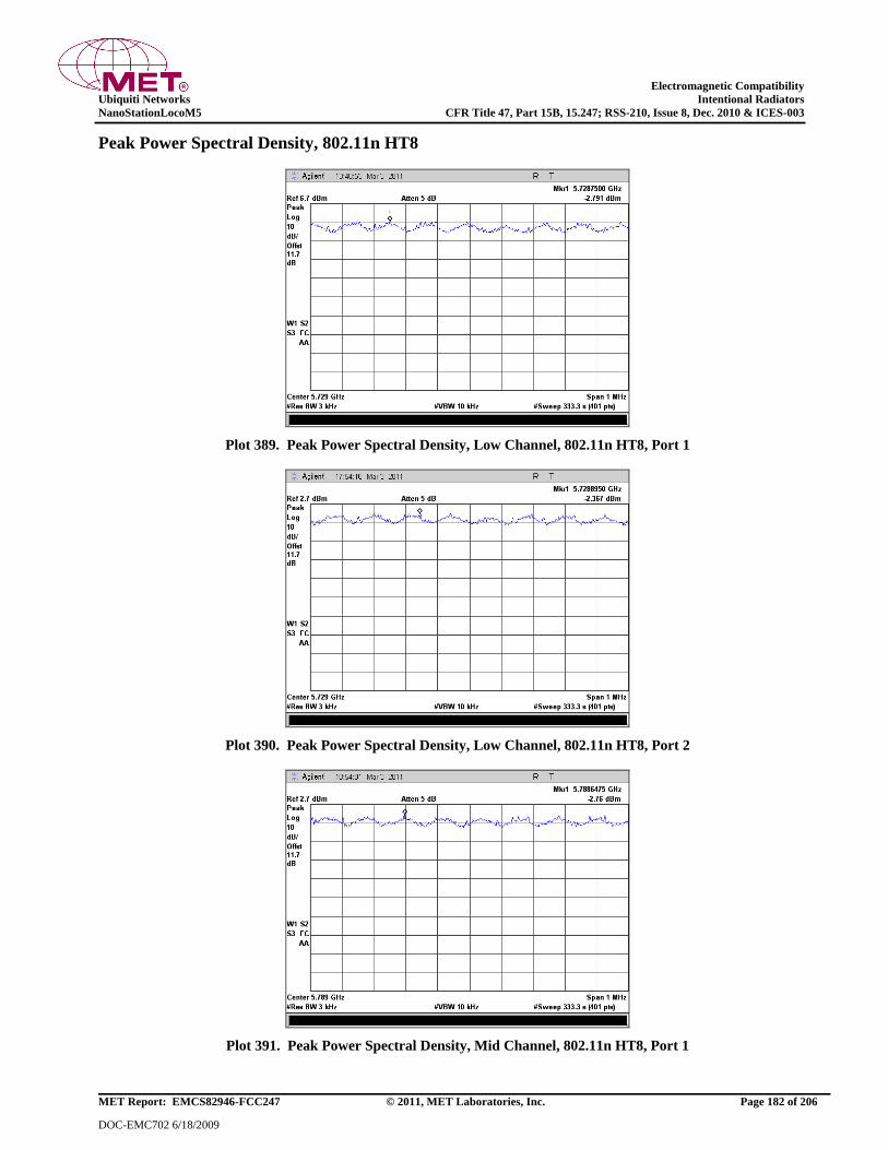
Electromagnetic Compatibility
Ubiquiti Networks Intentional Radiators
NanoStationLocoM5 CFR Title 47, Part 15B, 15.247; RSS-210, Issue 8, Dec. 2010 & ICES-003
MET Report: EMCS82946-FCC247 © 2011, MET Laboratories, Inc. Page 182 of 206
DOC-EMC702 6/18/2009
Peak Power Spectral Density, 802.11n HT8
Plot 389. Peak Power Spectral Density, Low Channel, 802.11n HT8, Port 1
Plot 390. Peak Power Spectral Density, Low Channel, 802.11n HT8, Port 2
Plot 391. Peak Power Spectral Density, Mid Channel, 802.11n HT8, Port 1
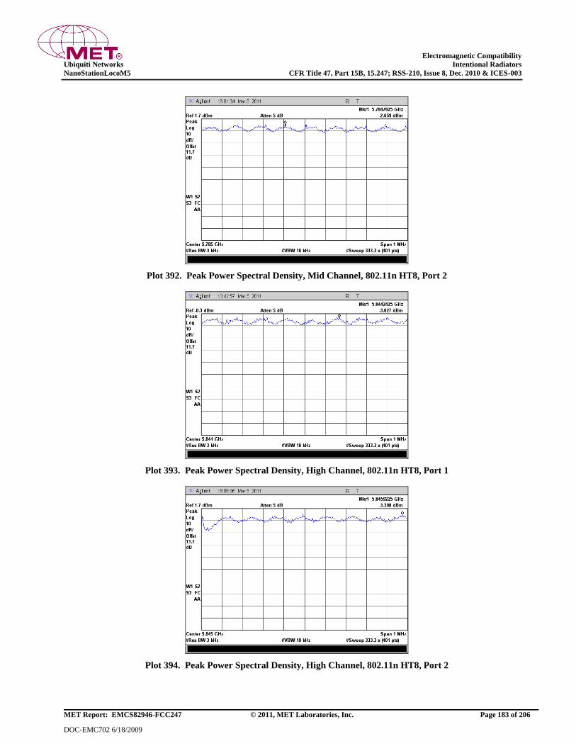
Electromagnetic Compatibility
Ubiquiti Networks Intentional Radiators
NanoStationLocoM5 CFR Title 47, Part 15B, 15.247; RSS-210, Issue 8, Dec. 2010 & ICES-003
MET Report: EMCS82946-FCC247 © 2011, MET Laboratories, Inc. Page 183 of 206
DOC-EMC702 6/18/2009
Plot 392. Peak Power Spectral Density, Mid Channel, 802.11n HT8, Port 2
Plot 393. Peak Power Spectral Density, High Channel, 802.11n HT8, Port 1
Plot 394. Peak Power Spectral Density, High Channel, 802.11n HT8, Port 2
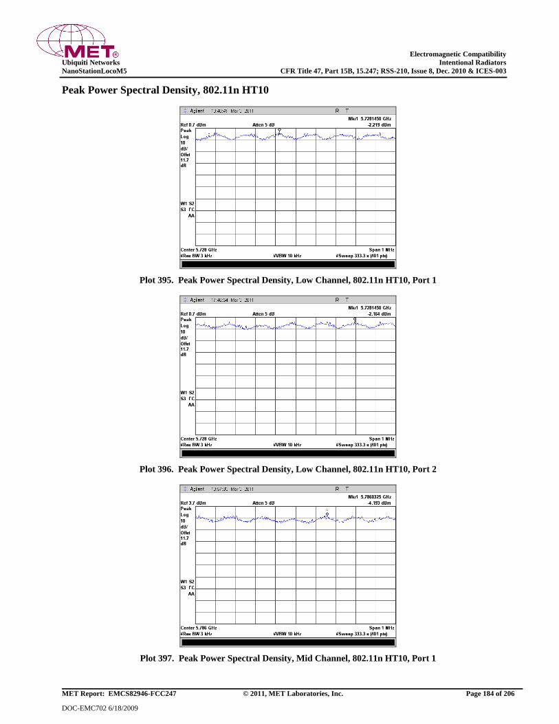
Electromagnetic Compatibility
Ubiquiti Networks Intentional Radiators
NanoStationLocoM5 CFR Title 47, Part 15B, 15.247; RSS-210, Issue 8, Dec. 2010 & ICES-003
MET Report: EMCS82946-FCC247 © 2011, MET Laboratories, Inc. Page 184 of 206
DOC-EMC702 6/18/2009
Peak Power Spectral Density, 802.11n HT10
Plot 395. Peak Power Spectral Density, Low Channel, 802.11n HT10, Port 1
Plot 396. Peak Power Spectral Density, Low Channel, 802.11n HT10, Port 2
Plot 397. Peak Power Spectral Density, Mid Channel, 802.11n HT10, Port 1
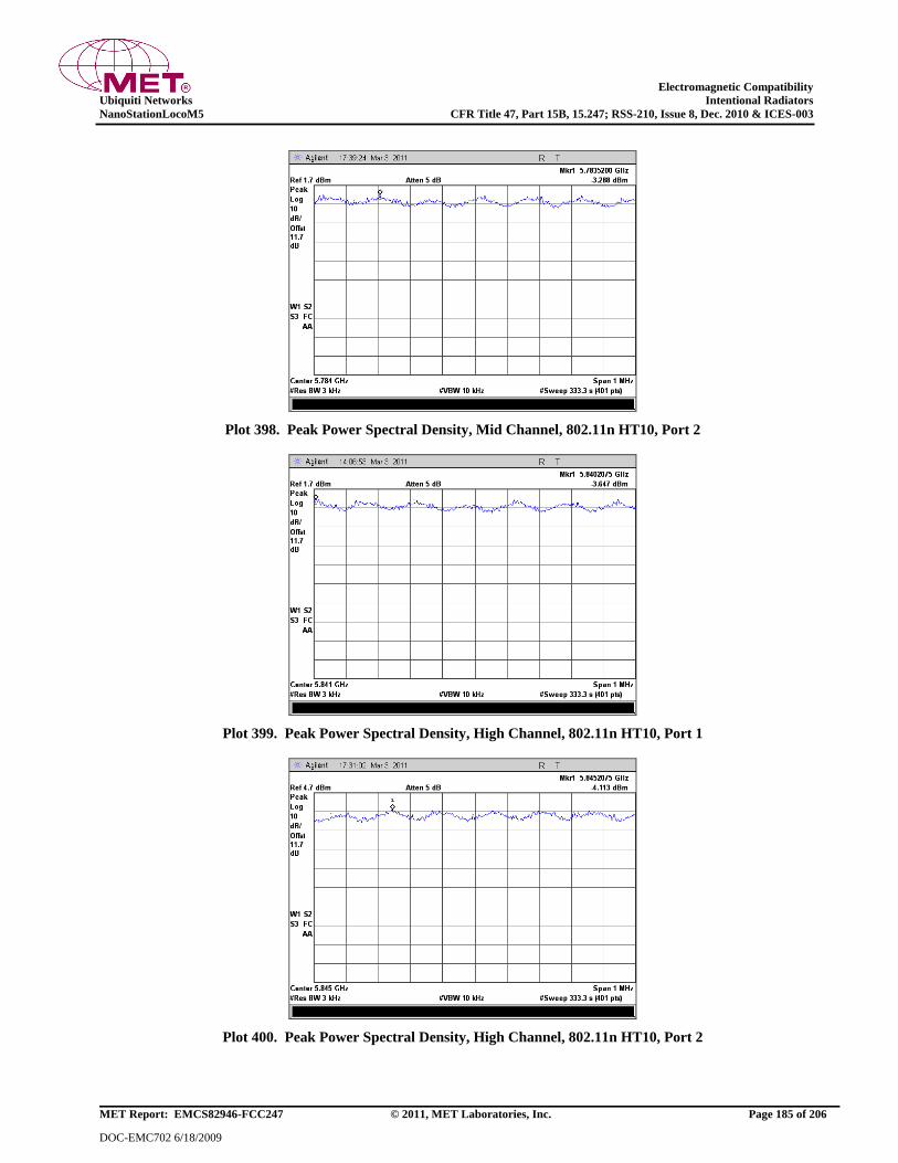
Electromagnetic Compatibility
Ubiquiti Networks Intentional Radiators
NanoStationLocoM5 CFR Title 47, Part 15B, 15.247; RSS-210, Issue 8, Dec. 2010 & ICES-003
MET Report: EMCS82946-FCC247 © 2011, MET Laboratories, Inc. Page 185 of 206
DOC-EMC702 6/18/2009
Plot 398. Peak Power Spectral Density, Mid Channel, 802.11n HT10, Port 2
Plot 399. Peak Power Spectral Density, High Channel, 802.11n HT10, Port 1
Plot 400. Peak Power Spectral Density, High Channel, 802.11n HT10, Port 2
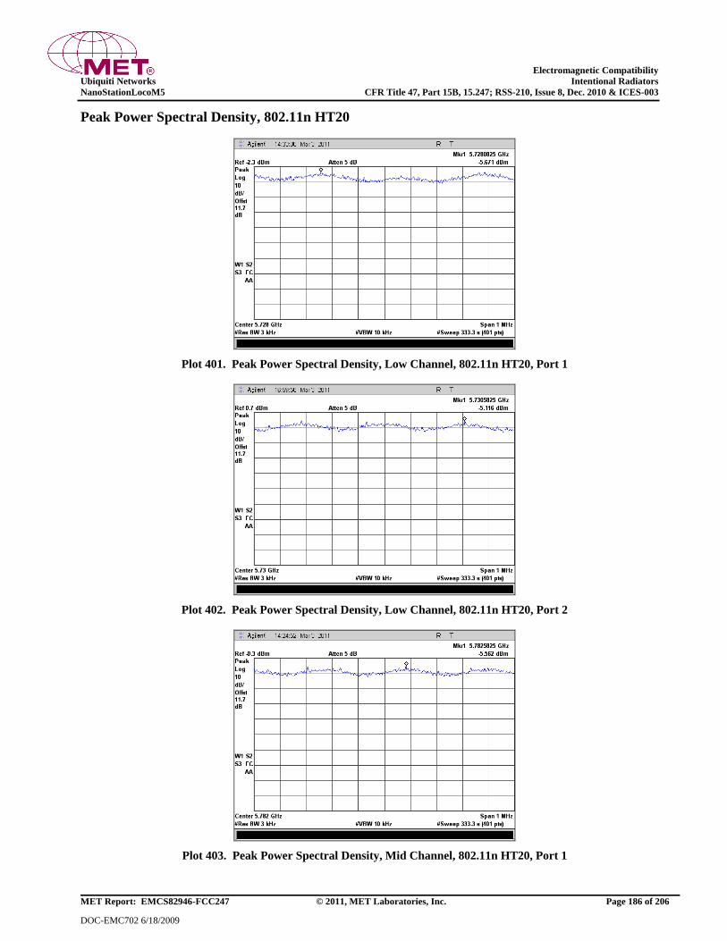
Electromagnetic Compatibility
Ubiquiti Networks Intentional Radiators
NanoStationLocoM5 CFR Title 47, Part 15B, 15.247; RSS-210, Issue 8, Dec. 2010 & ICES-003
MET Report: EMCS82946-FCC247 © 2011, MET Laboratories, Inc. Page 186 of 206
DOC-EMC702 6/18/2009
Peak Power Spectral Density, 802.11n HT20
Plot 401. Peak Power Spectral Density, Low Channel, 802.11n HT20, Port 1
Plot 402. Peak Power Spectral Density, Low Channel, 802.11n HT20, Port 2
Plot 403. Peak Power Spectral Density, Mid Channel, 802.11n HT20, Port 1

Electromagnetic Compatibility
Ubiquiti Networks Intentional Radiators
NanoStationLocoM5 CFR Title 47, Part 15B, 15.247; RSS-210, Issue 8, Dec. 2010 & ICES-003
MET Report: EMCS82946-FCC247 © 2011, MET Laboratories, Inc. Page 187 of 206
DOC-EMC702 6/18/2009
Plot 404. Peak Power Spectral Density, Mid Channel, 802.11n HT20, Port 2
Plot 405. Peak Power Spectral Density, High Channel, 802.11n HT20, Port 1
Plot 406. Peak Power Spectral Density, High Channel, 802.11n HT20, Port 2
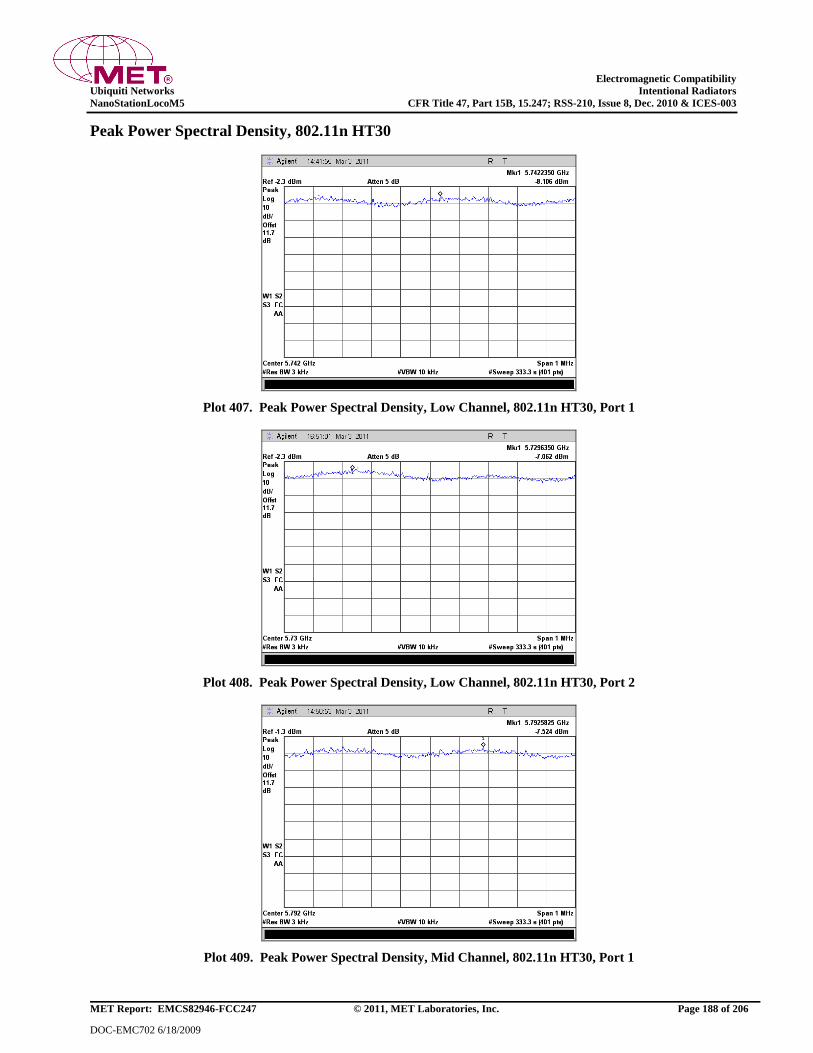
Electromagnetic Compatibility
Ubiquiti Networks Intentional Radiators
NanoStationLocoM5 CFR Title 47, Part 15B, 15.247; RSS-210, Issue 8, Dec. 2010 & ICES-003
MET Report: EMCS82946-FCC247 © 2011, MET Laboratories, Inc. Page 188 of 206
DOC-EMC702 6/18/2009
Peak Power Spectral Density, 802.11n HT30
Plot 407. Peak Power Spectral Density, Low Channel, 802.11n HT30, Port 1
Plot 408. Peak Power Spectral Density, Low Channel, 802.11n HT30, Port 2
Plot 409. Peak Power Spectral Density, Mid Channel, 802.11n HT30, Port 1
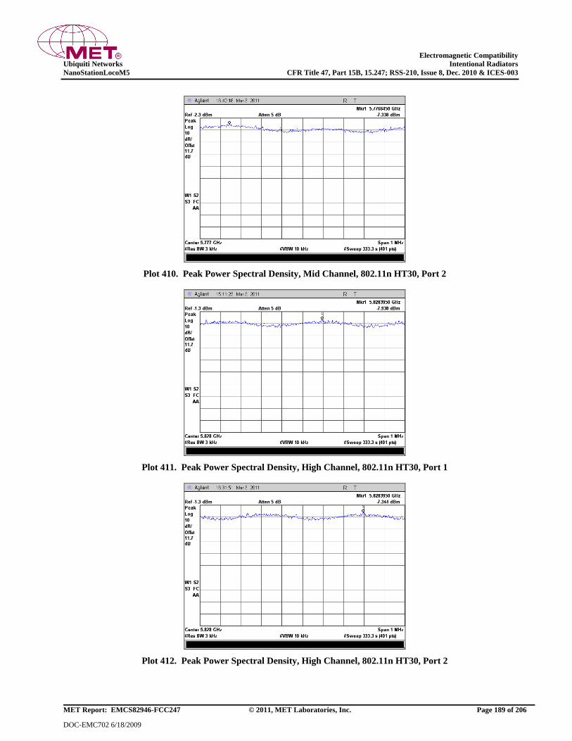
Electromagnetic Compatibility
Ubiquiti Networks Intentional Radiators
NanoStationLocoM5 CFR Title 47, Part 15B, 15.247; RSS-210, Issue 8, Dec. 2010 & ICES-003
MET Report: EMCS82946-FCC247 © 2011, MET Laboratories, Inc. Page 189 of 206
DOC-EMC702 6/18/2009
Plot 410. Peak Power Spectral Density, Mid Channel, 802.11n HT30, Port 2
Plot 411. Peak Power Spectral Density, High Channel, 802.11n HT30, Port 1
Plot 412. Peak Power Spectral Density, High Channel, 802.11n HT30, Port 2
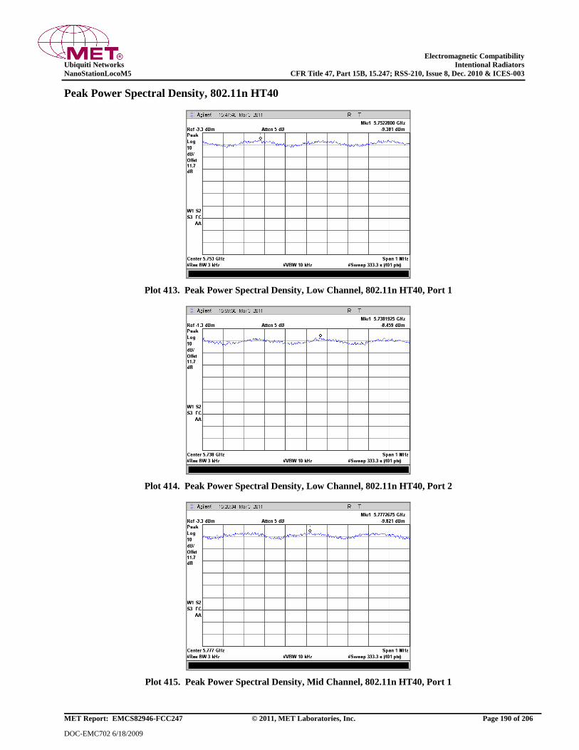
Electromagnetic Compatibility
Ubiquiti Networks Intentional Radiators
NanoStationLocoM5 CFR Title 47, Part 15B, 15.247; RSS-210, Issue 8, Dec. 2010 & ICES-003
MET Report: EMCS82946-FCC247 © 2011, MET Laboratories, Inc. Page 190 of 206
DOC-EMC702 6/18/2009
Peak Power Spectral Density, 802.11n HT40
Plot 413. Peak Power Spectral Density, Low Channel, 802.11n HT40, Port 1
Plot 414. Peak Power Spectral Density, Low Channel, 802.11n HT40, Port 2
Plot 415. Peak Power Spectral Density, Mid Channel, 802.11n HT40, Port 1

Electromagnetic Compatibility
Ubiquiti Networks Intentional Radiators
NanoStationLocoM5 CFR Title 47, Part 15B, 15.247; RSS-210, Issue 8, Dec. 2010 & ICES-003
MET Report: EMCS82946-FCC247 © 2011, MET Laboratories, Inc. Page 191 of 206
DOC-EMC702 6/18/2009
Plot 416. Peak Power Spectral Density, Mid Channel, 802.11n HT40, Port 2
Plot 417. Peak Power Spectral Density, High Channel, 802.11n HT40, Port 1
Plot 418. Peak Power Spectral Density, High Channel, 802.11n HT40, Port 2
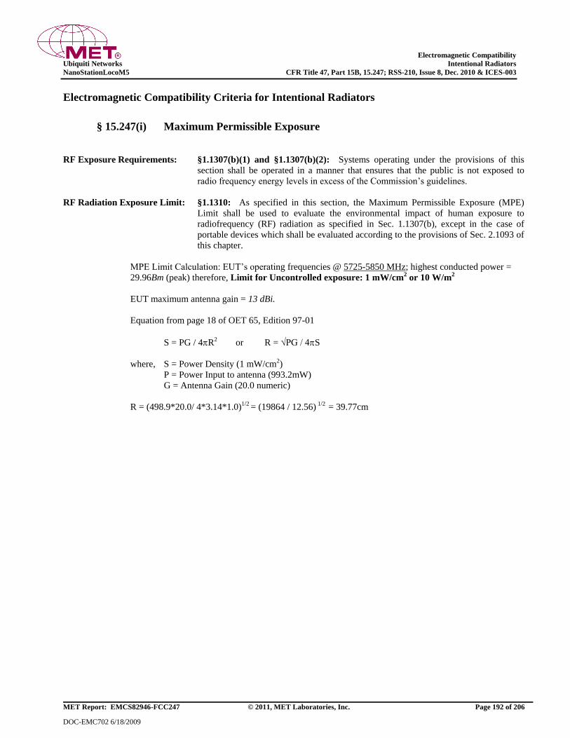
Electromagnetic Compatibility
Ubiquiti Networks Intentional Radiators
NanoStationLocoM5 CFR Title 47, Part 15B, 15.247; RSS-210, Issue 8, Dec. 2010 & ICES-003
MET Report: EMCS82946-FCC247 © 2011, MET Laboratories, Inc. Page 192 of 206
DOC-EMC702 6/18/2009
Electromagnetic Compatibility Criteria for Intentional Radiators
§ 15.247(i) Maximum Permissible Exposure
RF Exposure Requirements: §1.1307(b)(1) and §1.1307(b)(2): Systems operating under the provisions of this
section shall be operated in a manner that ensures that the public is not exposed to
radio frequency energy levels in excess of the Commission’s guidelines.
RF Radiation Exposure Limit: §1.1310: As specified in this section, the Maximum Permissible Exposure (MPE)
Limit shall be used to evaluate the environmental impact of human exposure to
radiofrequency (RF) radiation as specified in Sec. 1.1307(b), except in the case of
portable devices which shall be evaluated according to the provisions of Sec. 2.1093 of
this chapter.
MPE Limit Calculation: EUT’s operating frequencies @ 5725-5850 MHz; highest conducted power =
29.96Bm (peak) therefore, Limit for Uncontrolled exposure: 1 mW/cm2 or 10 W/m
2
EUT maximum antenna gain = 13 dBi.
Equation from page 18 of OET 65, Edition 97-01
S = PG / 4R2 or R = √PG / 4S
where, S = Power Density (1 mW/cm2)
P = Power Input to antenna (993.2mW)
G = Antenna Gain (20.0 numeric)
R = (498.9*20.0/ 4*3.14*1.0)1/2 = (19864 / 12.56) 1/2 = 39.77cm
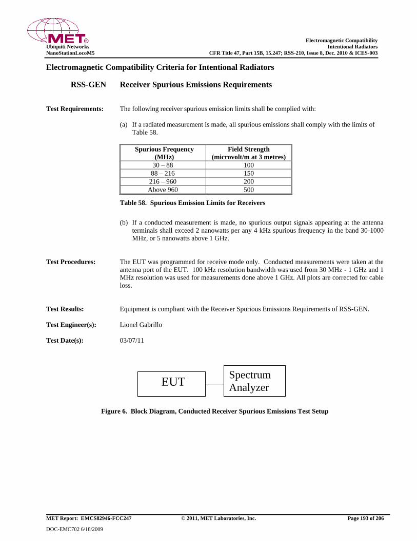
Electromagnetic Compatibility
Ubiquiti Networks Intentional Radiators
NanoStationLocoM5 CFR Title 47, Part 15B, 15.247; RSS-210, Issue 8, Dec. 2010 & ICES-003
MET Report: EMCS82946-FCC247 © 2011, MET Laboratories, Inc. Page 193 of 206
DOC-EMC702 6/18/2009
Electromagnetic Compatibility Criteria for Intentional Radiators
RSS-GEN Receiver Spurious Emissions Requirements
Test Requirements: The following receiver spurious emission limits shall be complied with:
(a) If a radiated measurement is made, all spurious emissions shall comply with the limits of
Table 58.
Spurious Frequency
(MHz)
Field Strength
(microvolt/m at 3 metres)
30 – 88 100
88 – 216 150
216 – 960 200
Above 960 500
Table 58. Spurious Emission Limits for Receivers
(b) If a conducted measurement is made, no spurious output signals appearing at the antenna
terminals shall exceed 2 nanowatts per any 4 kHz spurious frequency in the band 30-1000
MHz, or 5 nanowatts above 1 GHz.
Test Procedures: The EUT was programmed for receive mode only. Conducted measurements were taken at the
antenna port of the EUT. 100 kHz resolution bandwidth was used from 30 MHz - 1 GHz and 1
MHz resolution was used for measurements done above 1 GHz. All plots are corrected for cable
loss.
Test Results: Equipment is compliant with the Receiver Spurious Emissions Requirements of RSS-GEN.
Test Engineer(s): Lionel Gabrillo
Test Date(s): 03/07/11
Figure 6. Block Diagram, Conducted Receiver Spurious Emissions Test Setup
EUT Spectrum
Analyzer
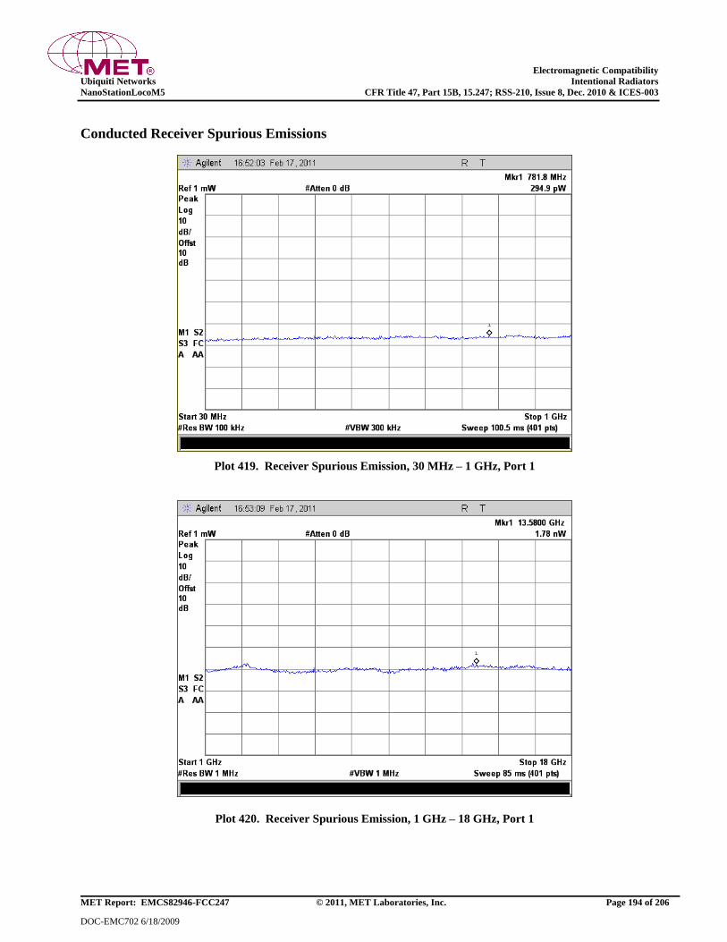
Electromagnetic Compatibility
Ubiquiti Networks Intentional Radiators
NanoStationLocoM5 CFR Title 47, Part 15B, 15.247; RSS-210, Issue 8, Dec. 2010 & ICES-003
MET Report: EMCS82946-FCC247 © 2011, MET Laboratories, Inc. Page 194 of 206
DOC-EMC702 6/18/2009
Conducted Receiver Spurious Emissions
Plot 419. Receiver Spurious Emission, 30 MHz – 1 GHz, Port 1
Plot 420. Receiver Spurious Emission, 1 GHz – 18 GHz, Port 1

Electromagnetic Compatibility
Ubiquiti Networks Intentional Radiators
NanoStationLocoM5 CFR Title 47, Part 15B, 15.247; RSS-210, Issue 8, Dec. 2010 & ICES-003
MET Report: EMCS82946-FCC247 © 2011, MET Laboratories, Inc. Page 195 of 206
DOC-EMC702 6/18/2009
Conducted Receiver Spurious Emissions
Plot 421. Receiver Spurious Emission, 30 MHz – 1 GHz, Port 2
Plot 422. Receiver Spurious Emission, 1 GHz – 18 GHz, Port 2
Electromagnetic Compatibility
Ubiquiti Networks Test Equipment
NanoStationLocoM5 CFR Title 47, Part 15B, 15.247; RSS-210, Issue 8, Dec. 2010 & ICES-003
MET Report: EMCS82946-FCC247 © 2011, MET Laboratories, Inc. Page 196 of 206
DOC-EMC702 6/18/2009
IV. Test Equipment
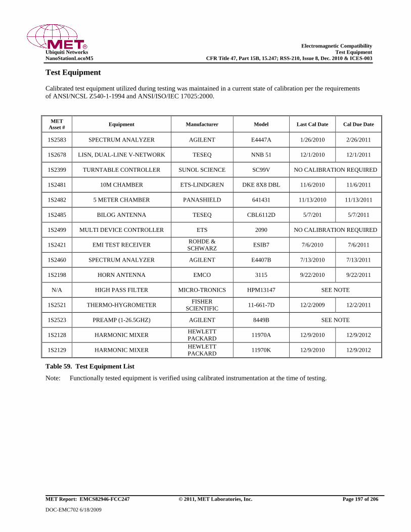
Electromagnetic Compatibility
Ubiquiti Networks Test Equipment
NanoStationLocoM5 CFR Title 47, Part 15B, 15.247; RSS-210, Issue 8, Dec. 2010 & ICES-003
MET Report: EMCS82946-FCC247 © 2011, MET Laboratories, Inc. Page 197 of 206
DOC-EMC702 6/18/2009
Test Equipment
Calibrated test equipment utilized during testing was maintained in a current state of calibration per the requirements
of ANSI/NCSL Z540-1-1994 and ANSI/ISO/IEC 17025:2000.
MET
Asset # Equipment Manufacturer Model Last Cal Date Cal Due Date
1S2583 SPECTRUM ANALYZER AGILENT E4447A 1/26/2010 2/26/2011
1S2678 LISN, DUAL-LINE V-NETWORK TESEQ NNB 51 12/1/2010 12/1/2011
1S2399 TURNTABLE CONTROLLER SUNOL SCIENCE SC99V NO CALIBRATION REQUIRED
1S2481 10M CHAMBER ETS-LINDGREN DKE 8X8 DBL 11/6/2010 11/6/2011
1S2482 5 METER CHAMBER PANASHIELD 641431 11/13/2010 11/13/2011
1S2485 BILOG ANTENNA TESEQ CBL6112D 5/7/201 5/7/2011
1S2499 MULTI DEVICE CONTROLLER ETS 2090 NO CALIBRATION REQUIRED
1S2421 EMI TEST RECEIVER ROHDE &
SCHWARZ ESIB7 7/6/2010 7/6/2011
1S2460 SPECTRUM ANALYZER AGILENT E4407B 7/13/2010 7/13/2011
1S2198 HORN ANTENNA EMCO 3115 9/22/2010 9/22/2011
N/A HIGH PASS FILTER MICRO-TRONICS HPM13147 SEE NOTE
1S2521 THERMO-HYGROMETER FISHER
SCIENTIFIC 11-661-7D 12/2/2009 12/2/2011
1S2523 PREAMP (1-26.5GHZ) AGILENT 8449B SEE NOTE
1S2128 HARMONIC MIXER HEWLETT
PACKARD 11970A 12/9/2010 12/9/2012
1S2129 HARMONIC MIXER HEWLETT
PACKARD 11970K 12/9/2010 12/9/2012
Table 59. Test Equipment List
Note: Functionally tested equipment is verified using calibrated instrumentation at the time of testing.
Electromagnetic Compatibility
Ubiquiti Networks Certification & User’s Manual Information
NanoStationLocoM5 CFR Title 47, Part 15B, 15.247; RSS-210, Issue 8, Dec. 2010 & ICES-003
MET Report: EMCS82946-FCC247 © 2011, MET Laboratories, Inc. Page 198 of 206
DOC-EMC702 6/18/2009
V. Certification & User’s Manual
Information
Electromagnetic Compatibility
Ubiquiti Networks Certification & User’s Manual Information
NanoStationLocoM5 CFR Title 47, Part 15B, 15.247; RSS-210, Issue 8, Dec. 2010 & ICES-003
MET Report: EMCS82946-FCC247 © 2011, MET Laboratories, Inc. Page 199 of 206
DOC-EMC702 6/18/2009
Certification & User’s Manual Information
A. Certification Information
The following is extracted from Title 47 of the Code of Federal Regulations, Part 2, Subpart I — Marketing of Radio
frequency devices:
§ 2.801 Radio-frequency device defined.
As used in this part, a radio-frequency device is any device which in its operation is capable of Emitting radio-frequency
energy by radiation, conduction, or other means. Radio- frequency devices include, but are not limited to:
(a) The various types of radio communication transmitting devices described throughout this chapter.
(b) The incidental, unintentional and intentional radiators defined in Part 15 of this chapter.
(c) The industrial, scientific, and medical equipment described in Part 18 of this chapter.
(d) Any part or component thereof which in use emits radio-frequency energy by radiation, conduction, or other
means.
§ 2.803 Marketing of radio frequency devices prior to equipment authorization.
(a) Except as provided elsewhere in this chapter, no person shall sell or lease, or offer for sale or lease (including
advertising for sale or lease), or import, ship or distribute for the purpose of selling or leasing or offering for sale
or lease, any radio frequency device unless:
(1) In the case of a device subject to certification, such device has been authorized by the Commission in
accordance with the rules in this chapter and is properly identified and labeled as required by §2.925 and
other relevant sections in this chapter; or
(2) In the case of a device that is not required to have a grant of equipment authorization issued by the
Commission, but which must comply with the specified technical standards prior to use, such device also
complies with all applicable administrative (including verification of the equipment or authorization under a
Declaration of Conformity, where required), technical, labeling and identification requirements specified in
this chapter.
(d) Notwithstanding the provisions of paragraph (a) of this section, the offer for sale solely to business, commercial,
industrial, scientific or medical users (but not an offer for sale to other parties or to end users located in a
residential environment) of a radio frequency device that is in the conceptual, developmental, design or pre-
production stage is permitted prior to equipment authorization or, for devices not subject to the equipment
authorization requirements, prior to a determination of compliance with the applicable technical requirements
provided that the prospective buyer is advised in writing at the time of the offer for sale that the equipment is
subject to the FCC rules and that the equipment will comply with the appropriate rules before delivery to the
buyer or to centers of distribution.
Electromagnetic Compatibility
Ubiquiti Networks Certification & User’s Manual Information
NanoStationLocoM5 CFR Title 47, Part 15B, 15.247; RSS-210, Issue 8, Dec. 2010 & ICES-003
MET Report: EMCS82946-FCC247 © 2011, MET Laboratories, Inc. Page 200 of 206
DOC-EMC702 6/18/2009
(e)(1) Notwithstanding the provisions of paragraph (a) of this section, prior to equipment authorization or
determination of compliance with the applicable technical requirements any radio frequency device may be
operated, but not marketed, for the following purposes and under the following conditions:
(i) Compliance testing;
(ii) Demonstrations at a trade show provided the notice contained in paragraph (c)
of this section is displayed in a conspicuous location on, or immediately adjacent to, the device;
(iii) Demonstrations at an exhibition conducted at a business, commercial, industrial, scientific or medical
location, but excluding locations in a residential environment, provided the notice contained in paragraphs (c)
or (d) of this section, as appropriate, is displayed in a conspicuous location on, or immediately adjacent to,
the device;
(iv) Evaluation of product performance and determination of customer acceptability, provided such operation
takes place at the manufacturer's facilities during developmental, design or pre-production states; or
(v) Evaluation of product performance and determination of customer acceptability where customer acceptability
of a radio frequency device cannot be determined at the manufacturer's facilities because of size or unique
capability of the device, provided the device is operated at a business, commercial, industrial, scientific or
medical user's site, but not at a residential site, during the development, design or pre-production stages.
(e)(2) For the purpose of paragraphs (e)(1)(iv) and (e)(1)(v) of this section, the term manufacturer's facilities includes
the facilities of the party responsible for compliance with the regulations and the manufacturer’s premises, as well
as the facilities of other entities working under the authorization of the responsible party in connection with the
development and manufacture, but not the marketing, of the equipment.
(f) For radio frequency devices subject to verification and sold solely to business, commercial, industrial, scientific
and medical users (excluding products sold to other parties or for operation in a residential environment), parties
responsible for verification of the devices shall have the option of ensuring compliance with the applicable
technical specifications of this chapter at each end user's location after installation, provided that the purchase or
lease agreement includes a proviso that such a determination of compliance be made and is the responsibility of
the party responsible for verification of the equipment.
Electromagnetic Compatibility
Ubiquiti Networks Certification & User’s Manual Information
NanoStationLocoM5 CFR Title 47, Part 15B, 15.247; RSS-210, Issue 8, Dec. 2010 & ICES-003
MET Report: EMCS82946-FCC247 © 2011, MET Laboratories, Inc. Page 201 of 206
DOC-EMC702 6/18/2009
Certification & User’s Manual Information
The following is extracted from Title 47 of the Code of Federal Regulations, Part 2, Subpart J — Equipment
Authorization Procedures:
§ 2.901 Basis and Purpose
(a) In order to carry out its responsibilities under the Communications Act and the various treaties and international
regulations, and in order to promote efficient use of the radio spectrum, the Commission has developed technical
standards for radio frequency equipment and parts or components thereof. The technical standards applicable to
individual types of equipment are found in that part of the rules governing the service wherein the equipment is to
be operated.1 In addition to the technical standards provided, the rules governing the service may require that
such equipment be verified by the manufacturer or importer, be authorized under a Declaration of Conformity, or
receive an equipment authorization from the Commission by one of the following procedures: certification or
registration.
(b) The following sections describe the verification procedure, the procedure for a Declaration of Conformity, and the
procedures to be followed in obtaining certification from the Commission and the conditions attendant to such a
grant.
§ 2.907 Certification.
(a) Certification is an equipment authorization issued by the Commission, based on representation and test data
submitted by the applicant.
(b) Certification attaches to all units subsequently marketed by the grantee which are identical (see Section 2.908) to
the sample tested except for permissive changes or other variations authorized by the Commission pursuant to
Section 2.1043.
1 In this case, the equipment is subject to the rules of Part 15. More specifically, the equipment falls under Subpart B
(of Part 15), which deals with unintentional radiators.
Electromagnetic Compatibility
Ubiquiti Networks Certification & User’s Manual Information
NanoStationLocoM5 CFR Title 47, Part 15B, 15.247; RSS-210, Issue 8, Dec. 2010 & ICES-003
MET Report: EMCS82946-FCC247 © 2011, MET Laboratories, Inc. Page 202 of 206
DOC-EMC702 6/18/2009
Certification & User’s Manual Information
§ 2.948 Description of measurement facilities.
(a) Each party making measurements of equipment that is subject to an equipment authorization under Part 15 or Part
18 of this chapter, regardless of whether the measurements are filed with the Commission or kept on file by the
party responsible for compliance of equipment marketed within the U.S. or its possessions, shall compile a
description of the measurement facilities employed.
(1) If the measured equipment is subject to the verification procedure, the description of the measurement
facilities shall be retained by the party responsible for verification of the equipment.
(i) If the equipment is verified through measurements performed by an independent laboratory, it is
acceptable for the party responsible for verification of the equipment to rely upon the
description of the measurement facilities retained by or placed on file with the Commission by
that laboratory. In this situation, the party responsible for the verification of the equipment is
not required to retain a duplicate copy of the description of the measurement facilities.
(ii) If the equipment is verified based on measurements performed at the installation site of the
equipment, no specific site calibration data is required. It is acceptable to retain the description
of the measurement facilities at the site at which the measurements were performed.
(2) If the equipment is to be authorized by the Commission under the certification procedure, the description
of the measurement facilities shall be filed with the Commission's Laboratory in Columbia, Maryland.
The data describing the measurement facilities need only be filed once but must be updated as changes
are made to the measurement facilities or as otherwise described in this section. At least every three
years, the organization responsible for filing the data with the Commission shall certify that the data on
file is current.
Electromagnetic Compatibility
Ubiquiti Networks Certification & User’s Manual Information
NanoStationLocoM5 CFR Title 47, Part 15B, 15.247; RSS-210, Issue 8, Dec. 2010 & ICES-003
MET Report: EMCS82946-FCC247 © 2011, MET Laboratories, Inc. Page 203 of 206
DOC-EMC702 6/18/2009
Certification & User’s Manual Information
1. Label and User’s Manual Information
The following is extracted from Title 47 of the Code of Federal Regulations, Part 15, Subpart A — General:
§ 15.19 Labeling requirements.
(a) In addition to the requirements in Part 2 of this chapter, a device subject to certification or verification shall be
labeled as follows:
(1) Receivers associated with the operation of a licensed radio service, e.g., FM broadcast under Part 73 of
this chapter, land mobile operation under Part 90, etc., shall bear the following statement in a
conspicuous location on the device:
This device complies with Part 15 of the FCC Rules. Operation is subject to the condition
that this device does not cause harmful interference.
(2) A stand-alone cable input selector switch, shall bear the following statement in a conspicuous location on
the device:
This device is verified to comply with Part 15 of the FCC Rules for use with cable
television service.
(3) All other devices shall bear the following statement in a conspicuous location on the device:
This device complies with Part 15 of the FCC Rules. Operation is subject to the following two
conditions: (1) This device may not cause harmful interference, and (2) this device must accept any
interference received, including interference that may cause undesired operation.
(4) Where a device is constructed in two or more sections connected by wires and marketed together, the
statement specified under paragraph (a) of this section is required to be affixed only to the main control
unit.
(5) When the device is so small or for such use that it is not practicable to place the statement specified
under paragraph (a) of this section on it, the information required by this paragraph shall be placed in a
prominent location in the instruction manual or pamphlet supplied to the user or, alternatively, shall be
placed on the container in which the device is marketed. However, the FCC identifier or the unique
identifier, as appropriate, must be displayed on the device.
§ 15.21 Information to user.
The users manual or instruction manual for an intentional or unintentional radiator shall caution the user that changes
or modifications not expressly approved by the party responsible for compliance could void the user's authority to
operate the equipment.
Electromagnetic Compatibility
Ubiquiti Networks Certification & User’s Manual Information
NanoStationLocoM5 CFR Title 47, Part 15B, 15.247; RSS-210, Issue 8, Dec. 2010 & ICES-003
MET Report: EMCS82946-FCC247 © 2011, MET Laboratories, Inc. Page 204 of 206
DOC-EMC702 6/18/2009
Verification & User’s Manual Information
The following is extracted from Title 47 of the Code of Federal Regulations, Part 15, Subpart B — Unintentional
Radiators:
§ 15.105 Information to the user.
(a) For a Class A digital device or peripheral, the instructions furnished the user shall include the following or
similar statement, placed in a prominent location in the text of the manual:
Note: This equipment has been tested and found to comply with the limits for a Class A digital device,
pursuant to Part 15 of the FCC Rules. These limits are designed to provide reasonable protection against
harmful interference when the equipment is operated in a commercial environment. This equipment
generates, uses, and can radiate radio frequency energy and, if not installed and used in accordance with
the instruction manual, may cause harmful interference to radio communications. Operation of this
equipment in a residential area is likely to cause harmful interference in which case the user will be
required to correct the interference at own expense.
(b) For a Class B digital device or peripheral, the instructions furnished the user shall include the following or
similar statement, placed in a prominent location in the text of the manual:
Note: This equipment has been tested and found to comply with the limits for a Class B digital
device, pursuant to Part 15 of the FCC Rules. These limits are designed to provide reasonable
protection against harmful interference when the equipment is operated in a residential
environment. This equipment generates, uses, and can radiate radio frequency energy and, if not
installed and used in accordance with the instruction manual, may cause harmful interference to
radio communications. However, there is no guarantee that interference will not occur in a
particular installation. If this equipment does cause harmful interference to radio or television
reception, which can be determined by turning the equipment off and on, the user is encouraged to
try to correct the interference by one or more of the following measures:
– Reorient or relocate the receiving antenna.
– Increase the separation between the equipment and receiver.
– Connect the equipment into an outlet on a circuit different from that to which the receiver is connected.
– Consult the dealer or an experienced radio/TV technician for help.
Electromagnetic Compatibility
Ubiquiti Networks Certification & User’s Manual Information
NanoStationLocoM5 CFR Title 47, Part 15B, 15.247; RSS-210, Issue 8, Dec. 2010 & ICES-003
MET Report: EMCS82946-FCC247 © 2011, MET Laboratories, Inc. Page 205 of 206
DOC-EMC702 6/18/2009
ICES-003 Procedural & Labeling Requirements
From the Industry Canada Electromagnetic Compatibility Advisory Bulletin entitled, ―Implementation and
Interpretation of the Interference-Causing Equipment Standard for Digital Apparatus, ICES-003" (EMCAB-3,
Issue 2, July 1995):
―At present, CISPR 22: 2002 and ICES technical requirements are essentially equivalent. Therefore, if
you have CISPR 22: 2002 approval by meeting CISPR Publication 22, the only additional requirements
are: to attach a note to the report of the test results for compliance, indicating that these results are
deemed satisfactory evidence of compliance with ICES-003 of the Canadian Interference-Causing
Equipment Regulations; to maintain these records on file for the requisite five year period; and to
provide the device with a notice of compliance in accordance with ICES-003.‖
Procedural Requirements:
According to Industry Canada’s Interference Causing Equipment Standard for Digital Apparatus ICES-
003 Issue 4, February 2004:
Section 6.1: A record of the measurements and results, showing the date that the measurements
were completed, shall be retained by the manufacturer or importer for a period of at
least five years from the date shown in the record and made available for examination
on the request of the Minister.
Section 6.2: A written notice indicating compliance must accompany each unit of digital apparatus
to the end user. The notice shall be in the form of a label that is affixed to the
apparatus. Where because of insufficient space or other constraints it is not feasible to
affix a label to the apparatus, the notice may be in the form of a statement in the user’s
manual.
Labeling Requirements:
The suggested text for the notice, in English and in French, is provided below, from the Annex of ICES-
003:
This Class [2] digital apparatus complies with Canadian ICES-003.
Cet appareil numérique de la classe [1] est conforme à la norme NMB-003 du Canada.
2 Insert either A or B but not both as appropriate for the equipment requirements.
Electromagnetic Compatibility
Ubiquiti Networks End of Report
NanoStationLocoM5 CFR Title 47, Part 15B, 15.247; RSS-210, Issue 8, Dec. 2010 & ICES-003
MET Report: EMCS82946-FCC247 © 2011, MET Laboratories, Inc. Page 206 of 206
DOC-EMC702 6/18/2009
End of Report