Embed Size (px)
Citation preview
Synthesizing ROOM Modelsfrom Message Sequence ChartSpeci�cationsStefan Leue, Lars Mehrmann, and Mohammad RezaiElectrical and Computer EngineeringUniversity of WaterlooWaterloo, Ontario N2L 3G1, CanadaTechnical Report 98-06c Stefan Leue, Lars Mehrmann, and Mohammad Rezai, 1998sleuelmehrman|[email protected] 1998
i
AbstractMessage Sequence Chart (MSC) speci�cations have found their way into many software en-gineering methodologies and CASE tools, in particular in the area of telecommunications andconcurrent real-time systems. MSC Speci�cations often represent early life-cycle requirementsand high-level design speci�cations. We are considering iterating and branching MSC speci�-cations according to ITU-T Recommendation Z.120. We show how these speci�cations can beanalyzed with respect to their software architectural content, including structure and behav-ior. We present algorithms for the automated synthesis of Real-Time Object-Oriented Modeling(ROOM) models from MSC speci�cations and discuss their implementation in theMesa toolset.The automation of the synthesis contributes to making the transition from high-level, messageexchange-oriented views to the level of a full life-cycle architecture description more e�cientand reliable. This means that we are contributing to making Z.120 MSC speci�cations moreuseful in the software engineering process.
Contents1 Introduction 12 Related Work 22.1 Message Sequence Chart Speci�cations . . . . . . . . . . . . . . . . . . . . . . . . . . 22.2 Real-Time Object Oriented Modeling (ROOM) . . . . . . . . . . . . . . . . . . . . . 42.3 Mesa . . . . . . . . . . . . . . . . . . . . . . . . . . . . . . . . . . . . . . . . . . . . 53 Architectural Content of MSC Speci�cations 63.1 Architectural Features in MSC Speci�cations . . . . . . . . . . . . . . . . . . . . . . 63.2 Representing Architectural Content of MSC Speci�cation in ROOM . . . . . . . . . 73.2.1 Structure . . . . . . . . . . . . . . . . . . . . . . . . . . . . . . . . . . . . . . 73.2.2 Behavior . . . . . . . . . . . . . . . . . . . . . . . . . . . . . . . . . . . . . . . 84 Synthesis Algorithms 94.1 Structure . . . . . . . . . . . . . . . . . . . . . . . . . . . . . . . . . . . . . . . . . . 94.2 Behavior . . . . . . . . . . . . . . . . . . . . . . . . . . . . . . . . . . . . . . . . . . . 104.2.1 Maximum Traceability Algorithm . . . . . . . . . . . . . . . . . . . . . . . . . 114.2.2 Maximum Progress Algorithm . . . . . . . . . . . . . . . . . . . . . . . . . . 154.3 Implementation in Mesa . . . . . . . . . . . . . . . . . . . . . . . . . . . . . . . . . 185 Use of Synthesized Models 186 A complex example: GSM Mobility Management 207 Conclusion 23A Formal Representation of the Synthesis Process iA.1 Formal De�nition of MSCs (from [5, 20]) . . . . . . . . . . . . . . . . . . . . . . . . . iA.2 Formal De�nition of ROOM Model . . . . . . . . . . . . . . . . . . . . . . . . . . . . iB Algorithms iiB.1 Algorithm for Structure Synthesis . . . . . . . . . . . . . . . . . . . . . . . . . . . . . iiB.2 Maximum Progress Algorithm for Behavior Synthesis . . . . . . . . . . . . . . . . . . iiB.3 Maximum Traceability Algorithm for Behavior Synthesis . . . . . . . . . . . . . . . . ivC Linear Form vC.1 Object Classes . . . . . . . . . . . . . . . . . . . . . . . . . . . . . . . . . . . . . . . viC.2 The ASCII �les . . . . . . . . . . . . . . . . . . . . . . . . . . . . . . . . . . . . . . . ixC.2.1 Toaster.package . . . . . . . . . . . . . . . . . . . . . . . . . . . . . . . . . ixC.2.2 ToasterSystem.actor . . . . . . . . . . . . . . . . . . . . . . . . . . . . . . . xC.2.3 Control.actor . . . . . . . . . . . . . . . . . . . . . . . . . . . . . . . . . . . xiC.2.4 ControlUserProtocol.port . . . . . . . . . . . . . . . . . . . . . . . . . . . xivC.2.5 ToasterSystemHeatingProtocol.port . . . . . . . . . . . . . . . . . . . . . xiviii

D Synthesis log �le xv
iv
List of Figures1 MSCs in the software lifecycle . . . . . . . . . . . . . . . . . . . . . . . . . . . . . . . 12 HMSC TOASTER (left) and bMSCs for TOASTER example . . . . . . . . . . . . . . . 33 Structure of HeatingSystem ROOM model . . . . . . . . . . . . . . . . . . . . . . . . 44 Behavior of HeatingSystem ROOM model . . . . . . . . . . . . . . . . . . . . . . . . 55 Structure of synthesized Toaster ROOM model . . . . . . . . . . . . . . . . . . . . . 96 Parts of synthesized behavior of actors Control and User,based on maximum trace-ability algorithm . . . . . . . . . . . . . . . . . . . . . . . . . . . . . . . . . . . . . . 117 Synthesized transition to resolve non-local choice in ROOM linear form . . . . . . . 128 Transition in ROOM involving hierarchical states . . . . . . . . . . . . . . . . . . . . 159 bMSC with message overtaking . . . . . . . . . . . . . . . . . . . . . . . . . . . . . . 1610 Behavior of Toaster model, synthesized by maximum progress algorithm . . . . . . . 1611 Simulation of synthesized ROOM model in ObjecTime . . . . . . . . . . . . . . . . . 1912 A generic representation of the GSM architecture layout . . . . . . . . . . . . . . . . 2013 The HMSC speci�cation of mobility management in a GSM network . . . . . . . . . 2114 The bMSCs referenced in the HMSC in Figure 13 . . . . . . . . . . . . . . . . . . . . 2215 The bMSCs referenced in the HMSC in Figure 13 (Cont.) . . . . . . . . . . . . . . . 2216 The synthesized models of the structure and behavior of the GSM example . . . . . 2417 OMT diagram of object classes of the linear form . . . . . . . . . . . . . . . . . . . . vi
v
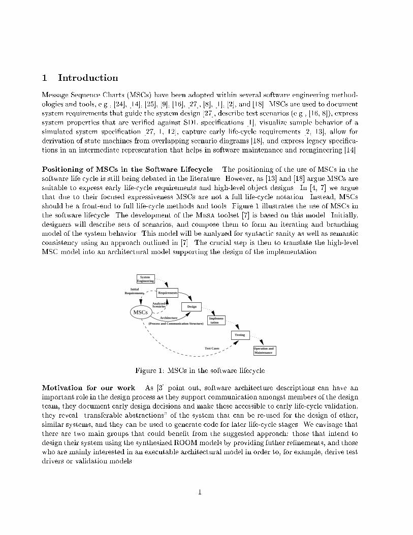
1 IntroductionMessage Sequence Charts (MSCs) have been adopted within several software engineering method-ologies and tools, e.g., [24], [14], [25], [9], [16], [27], [8], [1], [2], and [18]. MSCs are used to documentsystem requirements that guide the system design [27], describe test scenarios (e.g., [16, 8]), expresssystem properties that are veri�ed against SDL speci�cations [1], visualize sample behavior of asimulated system speci�cation [27, 1, 12], capture early life-cycle requirements [2, 13], allow forderivation of state machines from overlapping scenario diagrams [18], and express legacy speci�ca-tions in an intermediate representation that helps in software maintenance and reengineering [14].Positioning of MSCs in the Software Lifecycle. The positioning of the use of MSCs in thesoftware life cycle is still being debated in the literature. However, as [13] and [18] argue MSCs aresuitable to express early life-cycle requirements and high-level object designs. In [4, 7] we arguethat due to their focused expressiveness MSCs are not a full life-cycle notation. Instead, MSCsshould be a front-end to full life-cycle methods and tools. Figure 1 illustrates the use of MSCs inthe software lifecycle. The development of the Mesa toolset [7] is based on this model. Initially,designers will describe sets of scenarios, and compose them to form an iterating and branchingmodel of the system behavior. This model will be analyzed for syntactic sanity as well as semanticconsistency using an approach outlined in [7]. The crucial step is then to translate the high-levelMSC model into an architectural model supporting the design of the implementation.Testing
MaintenanceOperation and
Requirements
Implemen-tation
Design
System Engineering
AnalyzedScenarios
Initial Requirements
MSCsArchitecture
Test Cases
(Process and Communication Structure)
Figure 1: MSCs in the software lifecycleMotivation for our work. As [3] point out, software architecture descriptions can have animportant role in the design process as they support communication amongst members of the designteam, they document early design decisions and make these accessible to early life-cycle validation,they reveal \transferable abstractions" of the system that can be re-used for the design of other,similar systems, and they can be used to generate code for later life-cycle stages. We envisage thatthere are two main groups that could bene�t from the suggested approach: those that intend todesign their system using the synthesized ROOM models by providing futher re�nements, and thosewho are mainly interested in an executable architectural model in order to, for example, derive testdrivers or validation models. 1
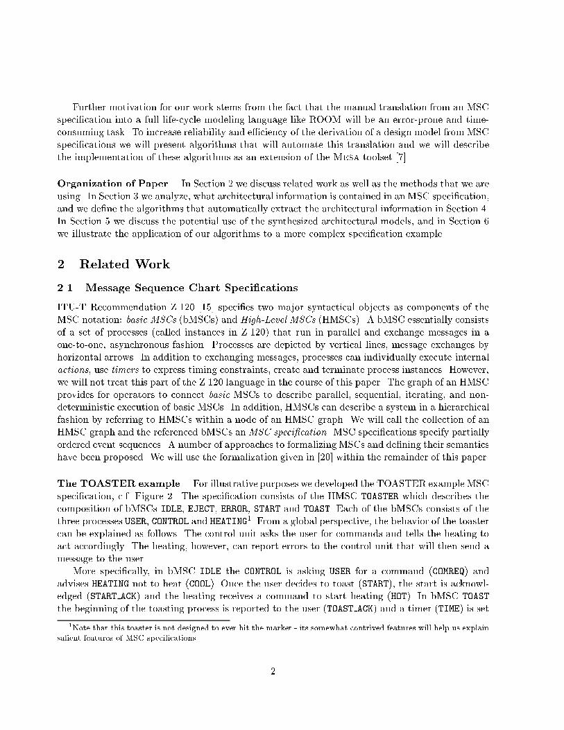
Further motivation for our work stems from the fact that the manual translation from an MSCspeci�cation into a full life-cycle modeling language like ROOM will be an error-prone and time-consuming task. To increase reliability and e�ciency of the derivation of a design model from MSCspeci�cations we will present algorithms that will automate this translation and we will describethe implementation of these algorithms as an extension of the Mesa toolset [7].Organization of Paper. In Section 2 we discuss related work as well as the methods that we areusing. In Section 3 we analyze, what architectural information is contained in an MSC speci�cation,and we de�ne the algorithms that automatically extract the architectural information in Section 4.In Section 5 we discuss the potential use of the synthesized architectural models, and in Section 6we illustrate the application of our algorithms to a more complex speci�cation example.2 Related Work2.1 Message Sequence Chart Speci�cationsITU-T Recommendation Z.120 [15] speci�es two major syntactical objects as components of theMSC notation: basic MSCs (bMSCs) and High-Level MSCs (HMSCs). A bMSC essentially consistsof a set of processes (called instances in Z.120) that run in parallel and exchange messages in aone-to-one, asynchronous fashion. Processes are depicted by vertical lines, message exchanges byhorizontal arrows. In addition to exchanging messages, processes can individually execute internalactions, use timers to express timing constraints, create and terminate process instances. However,we will not treat this part of the Z.120 language in the course of this paper. The graph of an HMSCprovides for operators to connect basic MSCs to describe parallel, sequential, iterating, and non-deterministic execution of basic MSCs. In addition, HMSCs can describe a system in a hierarchicalfashion by referring to HMSCs within a node of an HMSC graph. We will call the collection of anHMSC graph and the referenced bMSCs anMSC speci�cation. MSC speci�cations specify partiallyordered event sequences. A number of approaches to formalizing MSCs and de�ning their semanticshave been proposed. We will use the formalization given in [20] within the remainder of this paper.The TOASTER example. For illustrative purposes we developed the TOASTER example MSCspeci�cation, c.f. Figure 2. The speci�cation consists of the HMSC TOASTER which describes thecomposition of bMSCs IDLE, EJECT, ERROR, START and TOAST. Each of the bMSCs consists of thethree processes USER, CONTROL and HEATING1. From a global perspective, the behavior of the toastercan be explained as follows. The control unit asks the user for commands and tells the heating toact accordingly. The heating, however, can report errors to the control unit that will then send amessage to the user.More speci�cally, in bMSC IDLE the CONTROL is asking USER for a command (COMREQ) andadvises HEATING not to heat (COOL). Once the user decides to toast (START), the start is acknowl-edged (START ACK) and the heating receives a command to start heating (HOT). In bMSC TOASTthe beginning of the toasting process is reported to the user (TOAST ACK) and a timer (TIME) is set1Note that this toaster is not designed to ever hit the market - its somewhat contrived features will help us explainsalient features of MSC speci�cations. 2
USER CONTROL HEATING
HOT
START
START_ACK
MSC START
USER CONTROL HEATING
EMPTY
ERROR
RESET
MSC ERRORUSER CONTROL HEATING
EJECT
[2, 6]
EJECT_DONE
READY
MSC EJECT
USER CONTROL
TIME
10
TIME
HEATING
COMREQ
TOAST_ACK
WARM
[3, 5]
MSC TOAST
USER CONTROL HEATING
COMREQ
COOL
MSC IDLE
IDLE
TOAST
ERROR
EJECT
START
MSC TOASTER
Figure 2: HMSC TOASTER (left) and bMSCs for TOASTER exampleto ten time units to get a crusty toast. After the timer expires, the heating is switched to keep thetoast warm (WARM) and the user is asked by message COMREQ to choose between another toastingperiod or ejecting the slice of bread. The READY message will cause an EJECTmessage to the heatingwhich will respond with an EJECT DONE. The toaster returns to bMSC IDLE. When user asks forthe toasting process to start, heating will check whether there is a slice of bread in the toaster ornot. If not, it will send an ERROR message in bMSC ERROR and CONTROL will tell the user that athe toaster is empty (EMPTY). Note that in the remainder of the paper we will not interpret timerevents such as settings, resettings and expiry.Model synthesis based on Sequence Diagrams. Whereas we consider iterating and branch-ing type MSC speci�cations, most of the current approaches to synthesizing only consider �nitescenarios or MSC speci�cations. [29] describe algorithms to synthesize timed automata from theirown scenario description language. [26] describes the generation of test actors from basic MSCs.The model synthesis approach described by Koskimies et al. in [17, 18] is, to the best of our knowl-edge, the only other automated method that synthesizes state machine information from collectionsof more than one bMSC-like scenarios. However, the semantics of sets of scenarios that Koskimieset al. use is fundamentally di�erent from our usage: bMSCs in their approach (called `scenarios',reminiscent of the OMT notation) are overlapping. I.e. in a given scenario the behavior of a processis described from the beginning to the end. Each scenario corresponds to an alternative systemexecution and a process may at any given point in time be in di�erent scenarios. The state machinesynthesis proceeds by matching common sub-behavior in the di�erent scenarios. Composition ofbMSCs through Z.120 HMSCs as we use them here, however, assumes a mutually exclusive seman-tics: the control of a process lies in exactly one bMSC at any given point in time, and di�erentbMSCs are composed in a strictly sequential fashion2. Hence, our synthesis algorithms greatly varyfrom the ones used by Koskimies et al.2This interpretation of MSC composition coincides with the informal de�nitions in Z.120 and has also been chosenin [2, 13]. 3
tanktanktanktanktanktanktanktanktank
thermostatAdjustorthermostatAdjustorthermostatAdjustorthermostatAdjustorthermostatAdjustorthermostatAdjustorthermostatAdjustorthermostatAdjustorthermostatAdjustor
thermostatSensorR1thermostatSensorR1thermostatSensorR1thermostatSensorR1thermostatSensorR1thermostatSensorR1thermostatSensorR1thermostatSensorR1thermostatSensorR1
thermostatthermostatthermostatthermostatthermostatthermostatthermostatthermostatthermostatuserInterR1userInterR1userInterR1userInterR1userInterR1userInterR1userInterR1userInterR1userInterR1
thermostatAdjustorthermostatAdjustorthermostatAdjustorthermostatAdjustorthermostatAdjustorthermostatAdjustorthermostatAdjustorthermostatAdjustorthermostatAdjustor
thermostatSensorthermostatSensorthermostatSensorthermostatSensorthermostatSensorthermostatSensorthermostatSensorthermostatSensorthermostatSensor
userInterR1userInterR1userInterR1userInterR1userInterR1userInterR1userInterR1userInterR1userInterR1
ACTOR HeatingSystem
sensorsensorsensorsensorsensorsensorsensorsensorsensor
thermostatSensorR1thermostatSensorR1thermostatSensorR1thermostatSensorR1thermostatSensorR1thermostatSensorR1thermostatSensorR1thermostatSensorR1thermostatSensorR1
adjustoradjustoradjustoradjustoradjustoradjustoradjustoradjustoradjustor
thermostatHeaterR1thermostatHeaterR1thermostatHeaterR1thermostatHeaterR1thermostatHeaterR1thermostatHeaterR1thermostatHeaterR1thermostatHeaterR1thermostatHeaterR1
thermostatAdjustorthermostatAdjustorthermostatAdjustorthermostatAdjustorthermostatAdjustorthermostatAdjustorthermostatAdjustorthermostatAdjustorthermostatAdjustorthermostatSensorR1thermostatSensorR1thermostatSensorR1thermostatSensorR1thermostatSensorR1thermostatSensorR1thermostatSensorR1thermostatSensorR1thermostatSensorR1
ACTOR Tank
ACTOR Thermostat
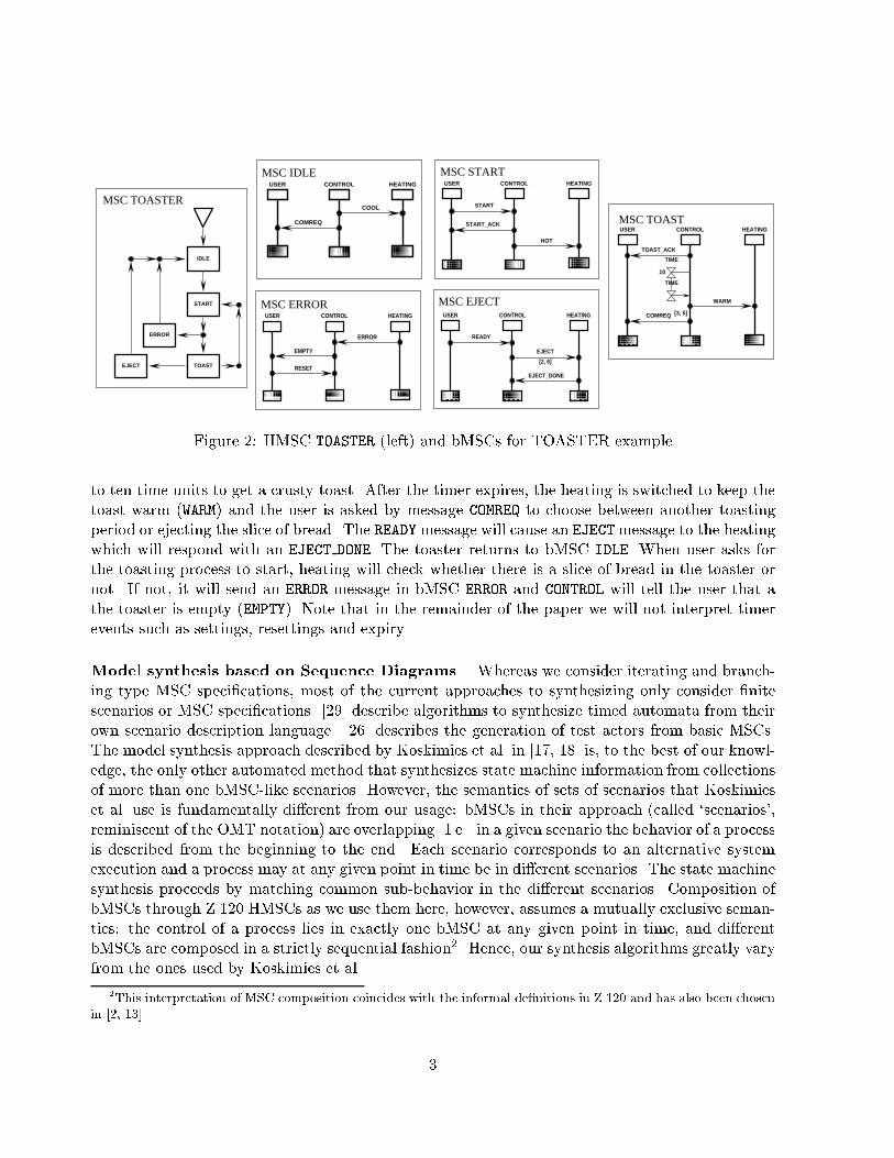
Figure 3: Structure of HeatingSystem ROOM model2.2 Real-Time Object Oriented Modeling (ROOM)The Real-Time Object Oriented Modeling (ROOM) [27] notation relies on two main components:the description of a system's structure and the dynamic behavior of the structural components.Structural components are de�ned as nested actor structures and their bindings. Behavior is de�nedusing a variant of Statecharts called ROOMcharts. ROOM is a graphical notation for which anequivalent textual syntax, called `linear form', has been de�ned in [27]. ROOM emphasizes seamlessuse of models from the requirements/high-level design phase down to the low-level design andtesting stages, although the notation seems to have de�cits when it comes to abstract requirementscapture. A bMSC-like notation is used within ROOM to represent requirements on inter-objectcommunications as well as execution traces of actual system runs. [3] have recently argued forthe use of ROOM as an Architecture Description Language. The ObjecTime Developer3 toolset[22] is an industrial-strength CASE tool implementing the ROOM methodology. It o�ers editing,simulation and code synthesis support for ROOM models. The linear form can be used withinObjecTime Developer to exchange ROOM model de�nitions with other CASE tools. The ROOMnotation is the basis for the currently ongoing de�nition of the UML Real-Time notation (c.f. [28]).The HeatingSystem example. Figures 3 and 4 show the structure and the behavior compo-nents of the ROOM model for a heating system. Space limitations do not permit us to discussthe complete ROOM notation here, for a complete presentation we refer to [27]. In Figure 3 thestructural elements of the Heating System are depicted. It consists of structural entities calledactors. The system is composed of actors thermostat and tank, where tank is being re�ned asconsisting of actors sensor and adjuster. Actors in ROOM may communicate via asynchronousmessage exchange. Protocols (not graphically represented) are lists of in (receive) and out (send)messages. To describe a communication path between two actors, e.g. tank and thermostat, onede�nes a port on each of the actors (i.e. thermostatAdjustor on tank and the identically namedport on thermostat) and connects them. This connection is called binding in ROOM. As protocols3ObjecTime Developer is a trademark of ObjecTime Limited.4
onStateonStateonStateonStateonStateonStateonStateonStateonStateoffStateoffStateoffStateoffStateoffStateoffStateoffStateoffStateoffState
initializeinitializeinitializeinitializeinitializeinitializeinitializeinitializeinitializesetsetsetsetsetsetsetsetset
offoffoffoffoffoffoffoffoff
ononononononononon
tempTooLowtempTooLowtempTooLowtempTooLowtempTooLowtempTooLowtempTooLowtempTooLowtempTooLowtempTooHottempTooHottempTooHottempTooHottempTooHottempTooHottempTooHottempTooHottempTooHot
tempOKtempOKtempOKtempOKtempOKtempOKtempOKtempOKtempOK
afterSetafterSetafterSetafterSetafterSetafterSetafterSetafterSetafterSetinitializeinitializeinitializeinitializeinitializeinitializeinitializeinitializeinitialize
tooLowtooLowtooLowtooLowtooLowtooLowtooLowtooLowtooLow
tooHot1tooHot1tooHot1tooHot1tooHot1tooHot1tooHot1tooHot1tooHot1
okokokokokokokokok
tooHottooHottooHottooHottooHottooHottooHottooHottooHot
tooLow1tooLow1tooLow1tooLow1tooLow1tooLow1tooLow1tooLow1tooLow1
okokokokokokokokok
okokokokokokokokok
tooLowtooLowtooLowtooLowtooLowtooLowtooLowtooLowtooLowtooHottooHottooHottooHottooHottooHottooHottooHottooHot
ononononononononon
setsetsetsetsetsetsetsetset setsetsetsetsetsetsetsetset
offoffoffoffoffoffoffoffoff
ACTOR: Thermostat STATE: top
ACTOR: Thermostat STATE: onState IN top
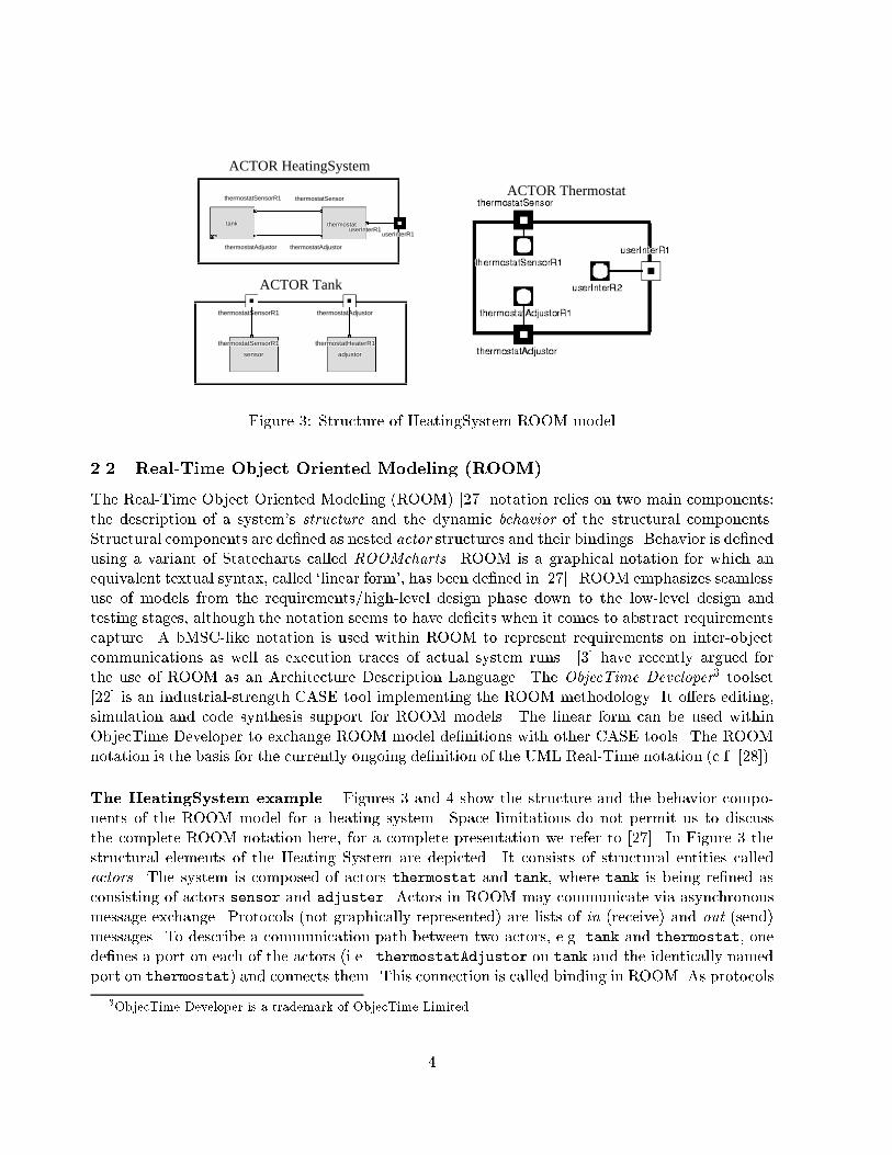
Figure 4: Behavior of HeatingSystem ROOM modelare distinguishing between in- and out messages they represent the view of just one of the com-munication partners. Therefore, to perform a binding two ports need to be of the same protocoltype (i.e., have identical sets of messages), but one of them needs to be conjugated compared tothe other, i.e. in and out messages need to be swapped in the conjugated protocol. The box onthe right hand side of Figure 3 represents the internal structure of actor thermostat which has nonested structure. However, it has a behavior representing state machine (see Figure 4) attached toit. Ports can be either relay ports as thermostatSensor which are responsible to convey messagesfrom one actor to another, or end ports like thermostatSensorR1 which hand messages over tothe ROOM state machines. Behavior is expressed in terms of hierarchical communicating extended�nite state machines called ROOMcharts, a variant of Statecharts. The top state in Figure 4 isre�ned into states offState and onState. The onState diagram on the right hand side of Figure4 consists of three di�erent states and transitions between them. Note that while the labels on thetransitions have meaningful names, e.g. \tooHot", these names are arbitrary and have no semanticsin the model. The transition semanitcs depends on the de�nition of the trigger events and transitioncode, which is not depicted in Figure 4. The on and set points on the state boundary de�ne theincoming transition points, and off and set de�ne the outgoing transition points. When incomingand outgoing transition points are not connected to a particular state, this means re-entry to, orexit from, the last state in which this state machine was. For a more complete description of theROOM notation we refer to [27].2.3 MesaTo support the use of Z.120 MSC speci�cations we have developed the Mesa toolset [7]. It al-lows for editing and storing Z.120 compliant MSC speci�cations. Furthermore, Mesa implementsalgorithms analyzing MSC speci�cations for syntactic anomalies like non-local choice and processdivergence [5] and for timing inconsistency [6]. Applying the syntactic sanity checks that we de�nedin [5] we �nd that the TOASTER MSC speci�cation features non-local choice. After going throughbMSC START either CONTROL starts the toasting process or HEATING sends the ERROR signal. Due tothe asynchronous nature of the processes that are involved there is the possibility that HEATING andand CONTROL will branch o� into di�erent directions which leads to a counterintuitive interpretation5
of the MSC speci�cation as well as to deadlocks. We will have to pay special attention to this whenwe synthesize executable architectural models from the speci�cation.Mesa is intended as a front-end to more comprehensive design notations and tools, e.g. ROOMand ObjecTime Developer, Hence, in the following Sections we will present algorithms that allowthe architectural content of an MSC speci�cation to be extracted and translated into a ROOMmodel, and we will illustrate the implementation of these algorithms within the Mesa toolset.3 Architectural Content of MSC Speci�cationsWe agree with [3] that there is \no single accepted de�nition of the term [software architecture]",largely due to the fact that software architecture is an emerging discipline. We are neverthelessinterested in determining what the architectural content of an MSC speci�cation is, based on aninterpretation of the notions of software architecture as discussed in [3]. As [3] argue, ROOMis suitable as an architecture description language (ADL). We discuss in this Section how thearchitectural content of MSC speci�cations can be represented in ROOM as a suitable ADL. Section4 will present the ROOM synthesis algorithms in more detail.3.1 Architectural Features in MSC Speci�cationsIn following [3], we understand a software architecture to be the structure of the system, comprisingthe software components, externally visible properties of these components and the relationshipamongst them. Furthermore, an architecture is an abstraction of the real system. Now, what arethe architectural features in MSC speci�cations? Out of the list of features that [3] o�ers we identifythe following as evident in MSC speci�cations:1. Process or coordination structure: in an MSC speci�cation this is given through the processesthat MSC speci�cation identi�es in its bMSCs. Note that our process structure is static andthat we do not consider MSC speci�cations with dynamic process creation or deletion. Tosome extent process structure also represents conceptual or logical structure, as de�ned in [3].2. Physical structure: this aspect relates to the hardware organization of the system. MSC spec-i�cations do not explicitly specify features of the hardware on which processes communicate.Nevertheless, they represent hardware communication channels. We have noted in past workthat a large number of assumptions concerning the properties of these channels are under-speci�ed in MSC speci�cations [19, 21]. Hence expressing the physical structure componentof the system architecture is not a strength of MSC speci�cations4.3. Call structure: Z.120 MSCs do not provide for representing call structures, although intro-duction of remote procedure call primitives is currently under study in the responsible ITU-Tstandardization committee. However, the Sequence Diagram notation as it is used in UML[9] allows for expressing procedure invocations in other, concurrent objects.4We are currently working on extending the MSC notation to represent communication channels and their prop-erties explicitly [10]. 6
4. Data ow: MSC speci�cations represent data ows as message ows. The \may send datato" relationship of [3] corresponds to the coordination relation as we de�ned it in [5]: any pair(pi; pj) of processes (for i 6= j) in the MSC speci�cation will be part of this relation i� there isat least one message sent from pi to pj in at least one of the bMSCs referenced in the HMSC.5. Control ow: bMSCs de�ne a strictly sequential control ow inside the processes. Composi-tion via HMSCs renders the control ow per process potentially branching and iterating.In conclusion, MSC speci�cations are strong in providing information about the system's processstructure, data ow and control ow; they are weaker when it comes to representing conceptualand call structures; and they o�er little support for expressing module, `uses' and class structure.3.2 Representing Architectural Content of MSC Speci�cation in ROOMWhen describing the architectural content of MSC speci�cations we will distinguish between struc-tural and behavioral5 components.3.2.1 StructureThe structural component of the architectural content of an MSC speci�cation will be representedin ROOM as follows:� ROOM requires all component actors to be part of an enclosing actor. We introduce asystem actor that does not have an explicit representation in an MSC speci�cation. An MSCspeci�cation implicitly de�nes a \system". This system corresponds to the system actor.� Every concurrent process in the MSC speci�cation will be represented by exactly one con-current ROOM actor6. As of now, MSC speci�cations do not express hierarchical nesting ofprocesses, hence the resulting actor structure in ROOM is at.� For every pair of distinct processes (pi; pj) that is member of the coordination relation therewill be the de�nition of exactly one ROOM protocol. In the de�nition of the protocol, one ofthe two processes will arbitrarily be chosen to represent the sending side of the communication,and all messages that it sends in all bMSCs to the other process will be part of the out signallist, the received messages form the in signal list.� Each protocol that has been de�ned for each process pi will result in an end port attached tothe corresponding actor. If and only if the actor has been picked as the receiving side of thecommunication in the previous step the resulting port will be conjugated (essentially, in andout lists will be swapped).5Note that [3] argue that \the behavior of each component is part of the architecture, insofar as that behavior canbe observed or discerned from the point of view of another component."6Note that consistency requirements for MSC speci�cations mandate that every bMSC in an MSC speci�cationconsists of the same set of processes. Mesa checks this as well as various other syntactic sanity constraints automat-ically. 7
� To represent the data ow in MSC speci�cations (which, in MSC speci�cations, is entirelymessage ow) we use ROOM bindings between ports. Note that ROOM only allows bindingsbetween ports representing a base protocol and its conjugate.3.2.2 BehaviorIn ROOM, behavior can be expressed using hierarchical communicating extended �nite state ma-chines called ROOMcharts.� MSC speci�cations describe sequences of send and receive communication events. This isexpressed through the strictly sequential control ow of each of the concurrently composedprocesses in an MSC speci�cation. Control passes from one local state of a process to thenext one when executing state transitions. The state transitions can either be caused by sendor by receive events. Hence, to represent this architectural feature we map local control statesof the bMSC processes to states in ROOMcharts.� We represent messages in bMSCs by ROOM signals. It is straightforward to map MSCreceive events to trigger events inside ROOMcharts. Reception of signals is the only possibletrigger for a ROOMchart transition. MSC send events are mapped to ROOM SEND primitives.These send out signals through a speci�ed port and they may be executed in the course of aROOMchart transition.� There will be no ROOMchart associated to the system actor that we de�ned above, but everyother actor will have a ROOMchart associated with it.Note that MSC speci�cations represent a signi�cant abstraction from the actual system behavior: 1)they represent send and receive events exclusively, no internal computation (we omit considerationof \internal events" and timer events from Z.120 MSCs), and 2) they represent message types only,no message parameters or data.When representing the behavior in state machine transitions, inevitably the question arises as tohow many events should be executed during one transition. Note that ROOM requires ROOMcharttransitions to be triggered by RECEIVE events exclusively7. This entails that a transition starts witheither a RECEIVE event as speci�ed in the MSC speci�cation, or with an auxiliary RECEIVE eventthat may be caused by self-sending of a message in the previous transition, or by the expiry of atimer.As an illustration, consider process CONTROL in Figure 2: reception of message START in bMSCSTART is certainly considered the trigger for a corresponding ROOMchart transition. But where isthis transition to terminate? We see the following possibilities:1. The transition terminates after executing exactly one event, i.e. the ?START event (we use `?'to denote a receive, and `!' to denote a send event). In this case, the next transition wouldhave to be triggered by an auxiliary RECEIVE event before executing !START ACK.7These RECEIVE events may originate from message exchanges or from expiring timers. Note that ROOM doesnot know \spontaneous" transitions as they can be found in SDL-92 [24] as well as many process algebras.8
toasterSystemHeatingProtocoltoasterSystemHeatingProtocoltoasterSystemHeatingProtocoltoasterSystemHeatingProtocoltoasterSystemHeatingProtocoltoasterSystemHeatingProtocoltoasterSystemHeatingProtocoltoasterSystemHeatingProtocoltoasterSystemHeatingProtocol
controlHeatingProtocolcontrolHeatingProtocolcontrolHeatingProtocolcontrolHeatingProtocolcontrolHeatingProtocolcontrolHeatingProtocolcontrolHeatingProtocolcontrolHeatingProtocolcontrolHeatingProtocol
Structure: ACTOR heating
toasterSystemControlProtocoltoasterSystemControlProtocoltoasterSystemControlProtocoltoasterSystemControlProtocoltoasterSystemControlProtocoltoasterSystemControlProtocoltoasterSystemControlProtocoltoasterSystemControlProtocoltoasterSystemControlProtocol
controlHeatingProtocolcontrolHeatingProtocolcontrolHeatingProtocolcontrolHeatingProtocolcontrolHeatingProtocolcontrolHeatingProtocolcontrolHeatingProtocolcontrolHeatingProtocolcontrolHeatingProtocol
controlUserProtocolcontrolUserProtocolcontrolUserProtocolcontrolUserProtocolcontrolUserProtocolcontrolUserProtocolcontrolUserProtocolcontrolUserProtocolcontrolUserProtocol
Structure: ACTOR control
useruseruseruseruseruseruseruserusertoasterSystemUserProtocoltoasterSystemUserProtocoltoasterSystemUserProtocoltoasterSystemUserProtocoltoasterSystemUserProtocoltoasterSystemUserProtocoltoasterSystemUserProtocoltoasterSystemUserProtocoltoasterSystemUserProtocol
controlUserProtocolcontrolUserProtocolcontrolUserProtocolcontrolUserProtocolcontrolUserProtocolcontrolUserProtocolcontrolUserProtocolcontrolUserProtocolcontrolUserProtocol
controlcontrolcontrolcontrolcontrolcontrolcontrolcontrolcontroltoasterSystemControlProtocoltoasterSystemControlProtocoltoasterSystemControlProtocoltoasterSystemControlProtocoltoasterSystemControlProtocoltoasterSystemControlProtocoltoasterSystemControlProtocoltoasterSystemControlProtocoltoasterSystemControlProtocol
controlHeatingProtocolcontrolHeatingProtocolcontrolHeatingProtocolcontrolHeatingProtocolcontrolHeatingProtocolcontrolHeatingProtocolcontrolHeatingProtocolcontrolHeatingProtocolcontrolHeatingProtocol
controlUserProtocolcontrolUserProtocolcontrolUserProtocolcontrolUserProtocolcontrolUserProtocolcontrolUserProtocolcontrolUserProtocolcontrolUserProtocolcontrolUserProtocol
heatingheatingheatingheatingheatingheatingheatingheatingheatingtoasterSystemHeatingProtocoltoasterSystemHeatingProtocoltoasterSystemHeatingProtocoltoasterSystemHeatingProtocoltoasterSystemHeatingProtocoltoasterSystemHeatingProtocoltoasterSystemHeatingProtocoltoasterSystemHeatingProtocoltoasterSystemHeatingProtocol
controlHeatingProtocolcontrolHeatingProtocolcontrolHeatingProtocolcontrolHeatingProtocolcontrolHeatingProtocolcontrolHeatingProtocolcontrolHeatingProtocolcontrolHeatingProtocolcontrolHeatingProtocol
toasterSystemHeatingProtocoltoasterSystemHeatingProtocoltoasterSystemHeatingProtocoltoasterSystemHeatingProtocoltoasterSystemHeatingProtocoltoasterSystemHeatingProtocoltoasterSystemHeatingProtocoltoasterSystemHeatingProtocoltoasterSystemHeatingProtocol
toasterSystemControlProtocoltoasterSystemControlProtocoltoasterSystemControlProtocoltoasterSystemControlProtocoltoasterSystemControlProtocoltoasterSystemControlProtocoltoasterSystemControlProtocoltoasterSystemControlProtocoltoasterSystemControlProtocol
toasterSystemUserProtocoltoasterSystemUserProtocoltoasterSystemUserProtocoltoasterSystemUserProtocoltoasterSystemUserProtocoltoasterSystemUserProtocoltoasterSystemUserProtocoltoasterSystemUserProtocoltoasterSystemUserProtocol
Structure: ToasterSystem
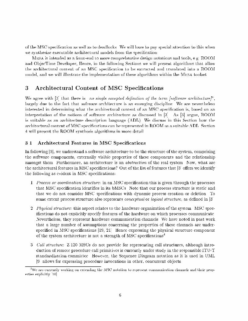
Figure 5: Structure of synthesized Toaster ROOM model2. The transition terminates before the next receive event, or whenever the last event in a bMSCis encountered. In this case the above mentioned transition would comprise events !START ACKand !HOT.3. The transition executes all send events until the next receive event is seen. If we followthe path in the HMSC graph from bMSC START via TOAST to EJECT, then the transitioncould comprise the event sequence !START ACK, !HOT, !TOAST ACK, !WARM and !COMREQ. Thisinterpretation clearly has the advantage that we do not need to introduce auxiliary triggerevents. Conversely, for pathological MSC speci�cations where one process would never receivean event this could lead to divergent behavior. In previous work we have de�ned algorithmsto syntactically detect such process divergence [5].We will discuss advantages and disadvantages of the above choices in Section 4.4 Synthesis AlgorithmsFollowing the structure of the two major building blocks of the ROOM language our synthesisalgorithm proceeds in two steps: �rst, the structure of the ROOM model will be generated. Thebehavior of the structural elements is generated in the second step. We discuss the synthesisalgorithms and illustrate their use with an example. Pseudo-code representations of the algorithmsare given in Appendix B.4.1 StructureThe structural elements in ROOM comprise actors, protocols, ports and bindings. A pseudo-codelevel formalization of the algorithm that we use to synthesize structure is presented in AppendixB.1. The algorithm has the following features:Actors: As we argued earlier, the algorithm creates exactly one actor for every process in theMSC speci�cation, plus a system actor. Figure 5 shows part of the structure for the Toastersystem as automatically generated by the Mesa toolset. At the center of the structure arethe three actors user, control and heating that form the ToasterSystem. Note that the9
ToasterSystem actor has been re�ned into the actors user, control and heating, as alsoshown in Figure 5.Protocols: The algorithm analyzes the coordination relation of the MSC speci�cation and gener-ates a pair of protocols for every pair of processes that is part of the coordination relation.The protocol consists of a set of in and a set of out signals. To compute the coordinationrelationship as well as the signal lists the synthesis algorithms performs a depth-�rst search onthe HMSC graph. When dereferencing an HMSC node the referenced bMSC will be analyzedand it will be determined which processes communicate with which others, if there are newcommunication relationships these will be added to the coordination relation. Further, it willbe recorded which messages will be exchanged for which communication relationship. Notethat a consistency requirement for MSC speci�cations mandates that every bMSC must havethe same set of processes.In the TOASTER example the algorithm detects the following coordination relation: f(user,control), (control, heating)g. Note that there is no communication relationship betweenuser and heating. Figure 5 depicts an ObjecTime protocol editor window showing theControlHeating protocol as derived from the Toaster MSC speci�cation. It is used bythe control actor to communicate with the heating actor.Ports and Binding: For each pair of processes in the coordination relation there will be a pair ofports on the corresponding pair of actors. Ports are labeled with the names of the protocolsthat they are using. Pairs of ports corresponding to pairs of processes in the coordinationrelation will be connected by a ROOM binding. One of the processes in each of these pairswill be selected and designated as the conjugate port. In Figure 5 the line between actorscontrol and heating represents such a binding. In the detailed structure of actors controland heating it can be seen that the ports labeled controlHeatingProtocol have di�er-ent graphical appearances { this indicates the conjugation of the associated protocols. TheControlHeating protocol for the controlHeatingProtocol port in actor heating has thelist of signals of in and out signals inverted compared to the ControlHeating protocol forthe controlHeatingProtocol port in actor control, which is depicted in Figure 5.System Actor: Finally, an enclosing system actor will be generated, c.f. the ToastSystem actorin Figure 5.We have not yet discussed the meaning of the end ports inside the ToasterSystem actor in Figure5. These are motivated by implementing branching choices in the HMSC graph. We will explaintheir meaning in the next Section when we discuss behavior synthesis.4.2 BehaviorEarlier on we discussed three alternatives for the termination of transitions. We immediately dismissthe �rst option which suggested to terminate a ROOMchart transition after every communicationevent. The resulting ROOMcharts would have many transitions that rely on auxiliary triggers tomodel send events in the MSC speci�cation. Hence, the �rst option would yield very complexROOM models that are in the danger of blurring the designers intentions. This leaves us with10
StartStartStartStartStartStartStartStartStart
EjectEjectEjectEjectEjectEjectEjectEjectEject
ErrorErrorErrorErrorErrorErrorErrorErrorError
ToastToastToastToastToastToastToastToastToast
IdleIdleIdleIdleIdleIdleIdleIdleIdle
initializeinitializeinitializeinitializeinitializeinitializeinitializeinitializeinitialize
StToStToStToStToStToStToStToStToStToStErStErStErStErStErStErStErStErStEr
EjIdEjIdEjIdEjIdEjIdEjIdEjIdEjIdEjId
ErIdErIdErIdErIdErIdErIdErIdErIdErId
ToStToStToStToStToStToStToStToStToSt
ToEjToEjToEjToEjToEjToEjToEjToEjToEj
IdStIdStIdStIdStIdStIdStIdStIdStIdStS1S1S1S1S1S1S1S1S1
ToStToStToStToStToStToStToStToStToStIdStIdStIdStIdStIdStIdStIdStIdStIdSt
StToStToStToStToStToStToStToStToStToStErStErStErStErStErStErStErStErStEr
StToStToStToStToStToStToStToStToStTo
ToStToStToStToStToStToStToStToStToStIdStIdStIdStIdStIdStIdStIdStIdStIdSt
StErStErStErStErStErStErStErStErStEr
S2S2S2S2S2S2S2S2S2
S1S1S1S1S1S1S1S1S1
StToStToStToStToStToStToStToStToStTo
ToStToStToStToStToStToStToStToStToSt ToEjToEjToEjToEjToEjToEjToEjToEjToEj
S1S2S1S2S1S2S1S2S1S2S1S2S1S2S1S2S1S2
ToEjToEjToEjToEjToEjToEjToEjToEjToEj
StToStToStToStToStToStToStToStToStTo
ToStToStToStToStToStToStToStToStToSt
ACTOR Control, STATE TOP ACTOR Control, STATE Start
ACTOR User, STATE Idle
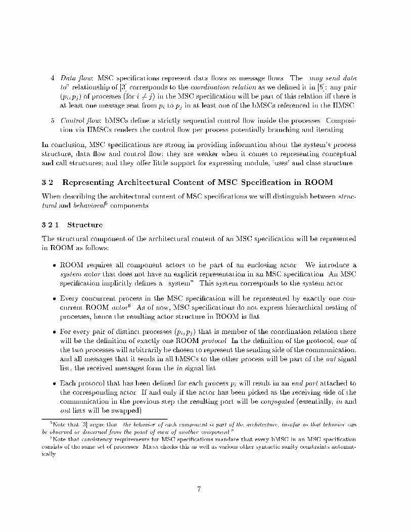
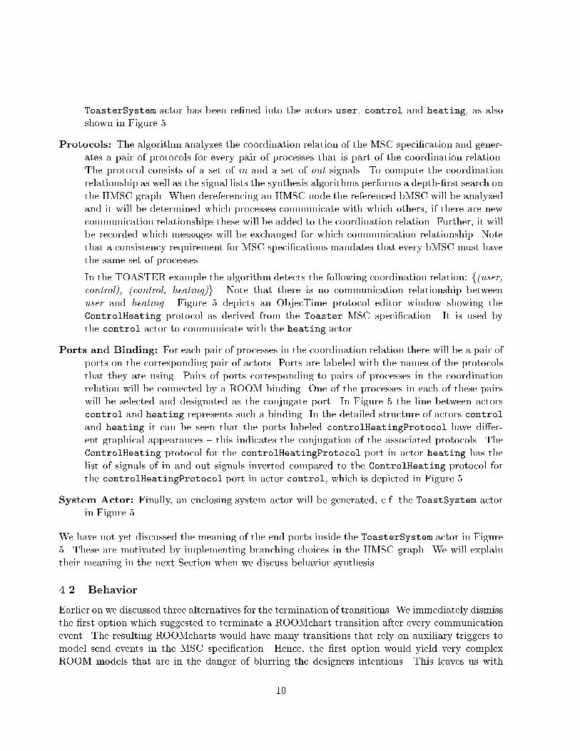
Figure 6: Parts of synthesized behavior of actors Control and User,based on maximum traceabilityalgorithmthe second and the third options, and we suggest two di�erent behavior synthesis algorithms toimplement these alternatives:Maximum Traceability: This algorithm implements the second termination alternative, i.e., atransition is terminated whenever a receive event inside a bMSC is encountered, and at thevery latest at the end of the bMSC in which the transition is triggered.Maximum Progress: This algorithm terminates a transition whenever the \next" receive eventis encountered. The next receive event does not have to be encountered in the same bMSC inwhich the transition was originally triggered. Finding the \next" event involves a traversal ofthe HMSC graph in oder to �nd a reachable bMSC in which a receive event is found. I.e., weallow the state machine to progress as far as possible in the HMSC graph before we terminatethe transition with the next receive event.There are two major di�erences between these algorithms. The maximum progress algorithm yieldspotentially smaller and hence more e�ciently executing models. However, let us assume that theHMSC graph of an MSC speci�cation expresses certain high-level design choices concerning thedecomposition of the system into phases of operation. Hence, the maximum traceability algorithmprovides a state machine that captures the designers intention with respect to the phase decom-position much more faithfully than the maximum progress algorithm, but the resulting modelmay execute less e�ciently. We will proceed with the discussion of both alternatives. For bothalgorithms we assume that the structure is already synthesized as described above.4.2.1 Maximum Traceability AlgorithmThe objective of this algorithm is to preserve traceability of components of the synthesized ROOMarchitecture with respect to the structure of the original MSC speci�cation. For every bMSCreferenced in the HMSC, and hence for every actor in the synthesized ROOM model, the followingsteps are performed: 11
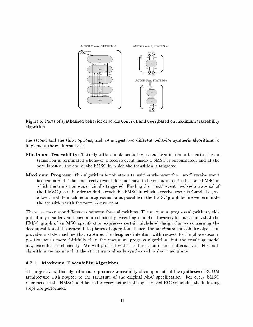
define StErfrom state S1to border transition StErtriggers{define signals {Error} on {controlHeatingProtocol};};define StTofrom state S1to border transition StTotriggers{define signals {Dostto} on {toasterSystemControlProtocol};};Figure 7: Synthesized transition to resolve non-local choice in ROOM linear form� All nodes of the HMSC graph are translated into top level states of the ROOMchart associatedwith each actor. The start node is converted to the initial point in the top level ROOMchart.Every interior node of the HMSC graph is mapped onto a state in the top level ROOMchart,and the name of the respective bMSC will be used as the name of the state it is associatedwith. Consider the top level state of the ROOMchart of the synthesized actor control inFigure 6 which consists of 5 states, each of them corresponding to one bMSC of Figure2. Nodes in an HMSC graph represent instances of the bMSC type that they refer to byname. Hence, when an HMSC refers to more than one instance of any given bMSC type, thealgorithm will use renaming to disambiguate the di�erent occurrences of this bMSC type.� All connecting edges of HMSC graph are converted into transitions in the top level ROOM-chart. Since edges in the HMSC graph do not have names, the corresponding transition namesare created using their source and destination state names, c.f. Figure 6.Concludingly, the HMSC graph structure will be mapped onto a ROOMchart top level state machineso that bMSCs in the HMSC graph correspond to states and HMSC edges correspond to top levelstate transitions. This choice entails preservation of the high level design structure, but it alsomeans that the state machines that re�ne the top level states must have transitions that terminateat the boundary of a bMSC. We will next consider how the states of the top level state machinewill be implemented.� The algorithm creates a basic ROOMchart for each bMSC reference in an HMSC. For ex-ample, consider the state Start, corresponding to bMSC START in the TOASTER exampleas depicted in Figure 6. For every node in the HMSC graph, each incoming HMSC edgewill be mapped onto exactly one incoming transition point in the corresponding lower levelROOMchart. In Figure 6 the state START has two incoming transitions, one labeled IdStrepresenting the (IDLE, START) edge and another one labeled ToSt representing the (TOAST,START) edge edge of the HMSC graph, respectively.For each bMSC node, the algorithms performs the following:12
1. For every process, it compiles a message list ML which comprises all communicationevents that this process executes in this bMSC. The entries are in the order of the eventshappening in the bMSC. The elements in the list are tuples of the form (S, T, A, D)where S is a local control state of the process, T is a triggering receive event, A is anaction, i.e., a send event, and D is a local successor state of the process.2. The algorithm proceeds with construction of the basic ROOMchart. The �rst elementof ML will be analyzed. If it corresponds to an entry that has a non-empty T element,i.e., it corresponds to a receive event, then a transition to a state D will be compiled.This transition comprises all entries in the list until either another entry correspondingto a receive event or the end of the list will be encountered. Compare the Start statein Figure 6, which consists of just one state, i.e. it terminates at the end of the ML list,with the Toast state.3. If the �rst message in a bMSC is a send message, then the generic timeout trigger T isused instead of a message receive event. The periodic timer T will be set to the smallestpossible time step value in the initial transition of the Top state of every actor.4. As a result of the above operations we obtain a temporary ordered list consisting of(transition, newstate) pairs. The �rst element in the list corresponds to the entry transi-tions into this basic ROOMchart, and we connect copies of this transition with the �rstnewstate that is encountered in the temporary list. C.f. the IdSt and ToSt transitionsin Figure 6 which connect to the respective incoming transition points. The newstatesin the temporary list are converted to states in the basic ROOMchart. They are calledS1; S2; :::. The transition names are created by combining the �rst two letters of thesource and destination states names.5. The �nal newstates in the temporary list are connected to all outgoing transition pointsof this basic ROOMchart, c.f. transitions StEr and StTo in state Start in Figure 6.� Transtions that involve a change of the high-level ROOMchart can be decomposed into com-ponents, as depicted in Figure 8. A branching in an HMSC translates into a change in thecorresponding ROOMchart. The choice with which ROOMchart to continue will be made inthe �rst of the three part transition. As a consequence, events that decide about a decisionmay be moved up to the predecessor state. As an example, the reception of message Startin state Start of actor Control in Figure 6 will be moved up to states Idle and Toast.� ROOM does not permit the de�nition of triggers on initial transitions. Therefore, if a statein the high-level ROOMchart is the successor of the initial point and the �rst message of thecorresponding bMSC is a receiving message, then an auxiliary state will be added, c.f. Figure6, the state S1 of actor User in state Idle.� Decisions in MSC speci�cations can either be local or non-local.Local Decisions: We represent local decisions as non-deterministic choices of the actor thatis sending the �rst message in the corresponding MSC choice. All other actors follow inthe direction that the �rst actor has chosen. In our synthesized model these decisionscould be either obtained by a random-number based algorithm, or by an interaction13
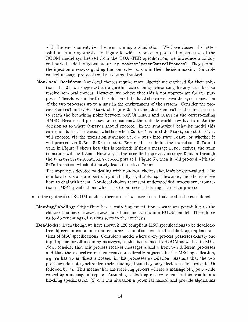
with the environment, i.e. the user running a simulation. We have chosen the lattersolution in our synthesis. In Figure 5, which represents part of the structure of theROOM model synthesized from the TOASTER speci�cation, we introduce auxiliaryend ports inside the system actor, e.g. toasterSystemControlProtocol. They permitthe injection messages guiding the connected actors in their decision making. Suitablecontrol message protocols will also be synthesized.Non-local Decisions: Non-local choices require more algorithmic overhead for their solu-tion. In [21] we suggested an algorithm based on synchronizing history variables toresolve non-local choices. However, we believe that this is not appropriate for our pur-poses. Therefore, similar to the solution of the local choice we leave the synchronizationof the two processes up to a user in the environment of the system. Consider the pro-cess Control in bMSC Start of Figure 2: Assume that Control is the �rst processto reach the branching point between bMSCs ERROR and TOAST in the correspondingHMSC. Because all processes are concurrent, the outside world now has to make thedecision as to where Control should proceed. In the synthesized behavior model thiscorresponds to the decision whether when Control is in state Start, sub-state S1, itwill proceed via the transition sequence StTo - StTo into state Toast, or whether itwill proceed via StEr - StEr into state Error. The code for the transitions StTo andStEr in Figure 7 shows how this is resolved: If �rst a message Error arrives, the StErtransition will be taken. However, if the user �rst injects a message Dostto throughthe toasterSystemControlProtocol port (c.f. Figure 5), then it will proceed with theStTo transition which ultimately leads into state Toast.The apparatus devoted to dealing with non-local choices shouldn't be over-valued. Thenon-local decisions are part of syntactically legal MSC speci�cations, and therefore wehave to deal with them. Non-local choices represent underspeci�ed process synchroniza-tion in MSC speci�cations which has to be rectivied during the design process.� In the synthesis of ROOM models, there are a few more issues that need to be considered:Naming/labeling: ObjecTime has certain implementation constraints pertaining to thechoice of names of states, state transitions and actors in a ROOM model. These forceus to do renamings of various sorts in the synthesis.Deadlocks: Even though we have shown Z.120 compliant MSC speci�cations to be deadlock-free [5] certain communication resource assumptions can lead to blocking implementa-tions of MSC speci�cations. Consider a model where every process possesses exactly oneinput queue for all incoming messages, as this is assumed in ROOM as well as in SDL.Now, consider that this process receives messages a and b from two di�erent processesand that the respective receive events are directly adjacent in the MSC speci�cation,e.g. ?a has ?b as direct successor in this processes ne relation. Assume that the twoprocesses do not synchronize their sending, then they may decide to �rst execute !bfollowed by !a. This means that the receiving process will see a message of type b whileexpecting a message of type a. Assuming a blocking receive semantics this results in ablocking speci�cation. [2] call this situation a potential hazard and provide algorithms14
A C
S1
S2
S3
S4
S12 S34
B1
B3
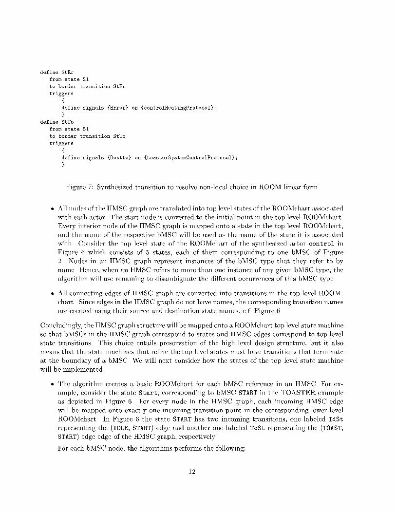
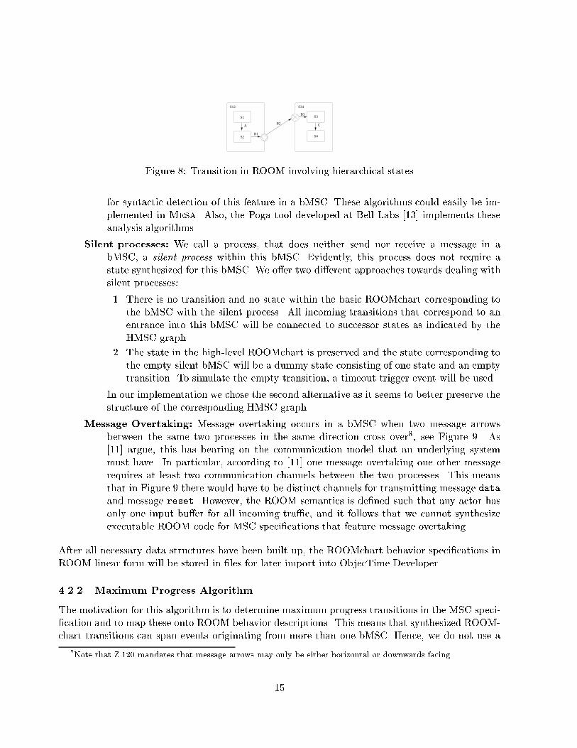
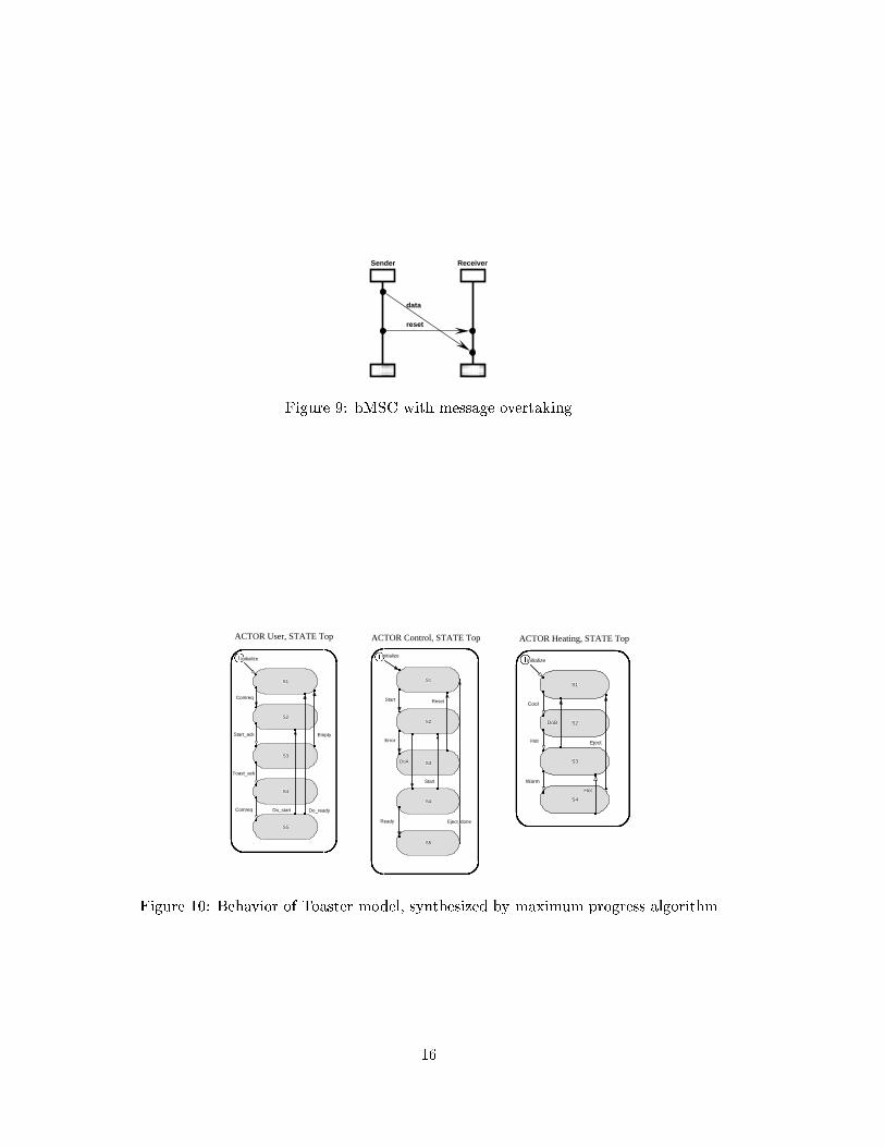
B2Figure 8: Transition in ROOM involving hierarchical statesfor syntactic detection of this feature in a bMSC. These algorithms could easily be im-plemented in Mesa. Also, the Poga tool developed at Bell Labs [13] implements theseanalysis algorithms.Silent processes: We call a process, that does neither send nor receive a message in abMSC, a silent process within this bMSC. Evidently, this process does not require astate synthesized for this bMSC. We o�er two di�erent approaches towards dealing withsilent processes:1. There is no transition and no state within the basic ROOMchart corresponding tothe bMSC with the silent process. All incoming transitions that correspond to anentrance into this bMSC will be connected to successor states as indicated by theHMSC graph.2. The state in the high-level ROOMchart is preserved and the state corresponding tothe empty silent bMSC will be a dummy state consisting of one state and an emptytransition. To simulate the empty transition, a timeout trigger event will be used.In our implementation we chose the second alternative as it seems to better preserve thestructure of the corresponding HMSC graph.Message Overtaking: Message overtaking occurs in a bMSC when two message arrowsbetween the same two processes in the same direction cross over8, see Figure 9. As[11] argue, this has bearing on the communication model that an underlying systemmust have. In particular, according to [11] one message overtaking one other messagerequires at least two communication channels between the two processes. This meansthat in Figure 9 there would have to be distinct channels for transmitting message dataand message reset. However, the ROOM semantics is de�ned such that any actor hasonly one input bu�er for all incoming tra�c, and it follows that we cannot synthesizeexecutable ROOM code for MSC speci�cations that feature message overtaking.After all necessary data structures have been built up, the ROOMchart behavior speci�cations inROOM linear form will be stored in �les for later import into ObjecTime Developer.4.2.2 Maximum Progress AlgorithmThe motivation for this algorithm is to determine maximum progress transitions in the MSC speci-�cation and to map these onto ROOM behavior descriptions. This means that synthesized ROOM-chart transitions can span events originating from more than one bMSC. Hence, we do not use a8Note that Z.120 mandates that message arrows may only be either horizontal or downwards facing.15
Sender Receiver
data
resetFigure 9: bMSC with message overtaking
S5S5S5S5S5S5S5S5S5
S4S4S4S4S4S4S4S4S4
S3S3S3S3S3S3S3S3S3
S2S2S2S2S2S2S2S2S2
S1S1S1S1S1S1S1S1S1
initializeinitializeinitializeinitializeinitializeinitializeinitializeinitializeinitialize
Do_readyDo_readyDo_readyDo_readyDo_readyDo_readyDo_readyDo_readyDo_readyDo_startDo_startDo_startDo_startDo_startDo_startDo_startDo_startDo_startComreqComreqComreqComreqComreqComreqComreqComreqComreq
Toast_ackToast_ackToast_ackToast_ackToast_ackToast_ackToast_ackToast_ackToast_ack
EmptyEmptyEmptyEmptyEmptyEmptyEmptyEmptyEmptyStart_ackStart_ackStart_ackStart_ackStart_ackStart_ackStart_ackStart_ackStart_ack
ComreqComreqComreqComreqComreqComreqComreqComreqComreq
ACTOR User, STATE Top
S3S3S3S3S3S3S3S3S3
S5S5S5S5S5S5S5S5S5
S4S4S4S4S4S4S4S4S4
S2S2S2S2S2S2S2S2S2
S1S1S1S1S1S1S1S1S1
initializeinitializeinitializeinitializeinitializeinitializeinitializeinitializeinitialize
ResetResetResetResetResetResetResetResetReset
Eject_doneEject_doneEject_doneEject_doneEject_doneEject_doneEject_doneEject_doneEject_done
StartStartStartStartStartStartStartStartStart
ReadyReadyReadyReadyReadyReadyReadyReadyReady
ErrorErrorErrorErrorErrorErrorErrorErrorError
DoADoADoADoADoADoADoADoADoA
StartStartStartStartStartStartStartStartStart
ACTOR Control, STATE Top
S4S4S4S4S4S4S4S4S4
S3S3S3S3S3S3S3S3S3
S2S2S2S2S2S2S2S2S2
S1S1S1S1S1S1S1S1S1
initializeinitializeinitializeinitializeinitializeinitializeinitializeinitializeinitialize
HotHotHotHotHotHotHotHotHot
EjectEjectEjectEjectEjectEjectEjectEjectEject
WarmWarmWarmWarmWarmWarmWarmWarmWarm
DoBDoBDoBDoBDoBDoBDoBDoBDoB
HotHotHotHotHotHotHotHotHot
CoolCoolCoolCoolCoolCoolCoolCoolCool
ACTOR Heating, STATE Top
Figure 10: Behavior of Toaster model, synthesized by maximum progress algorithm16
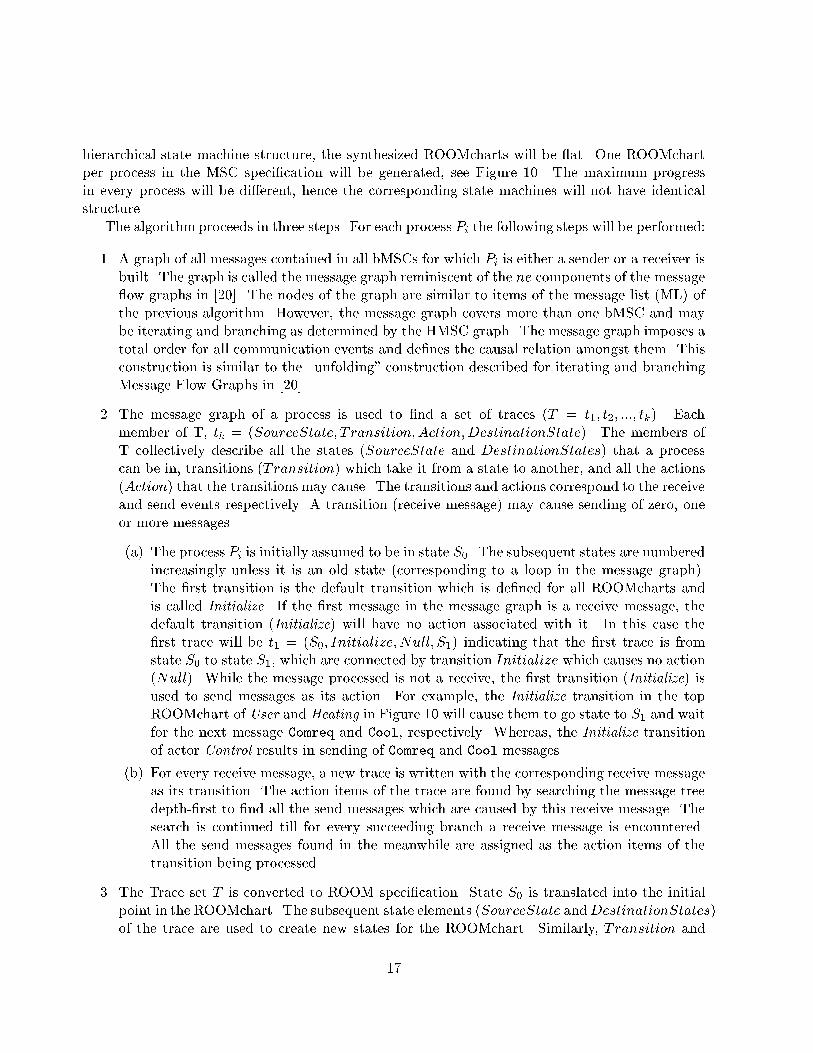
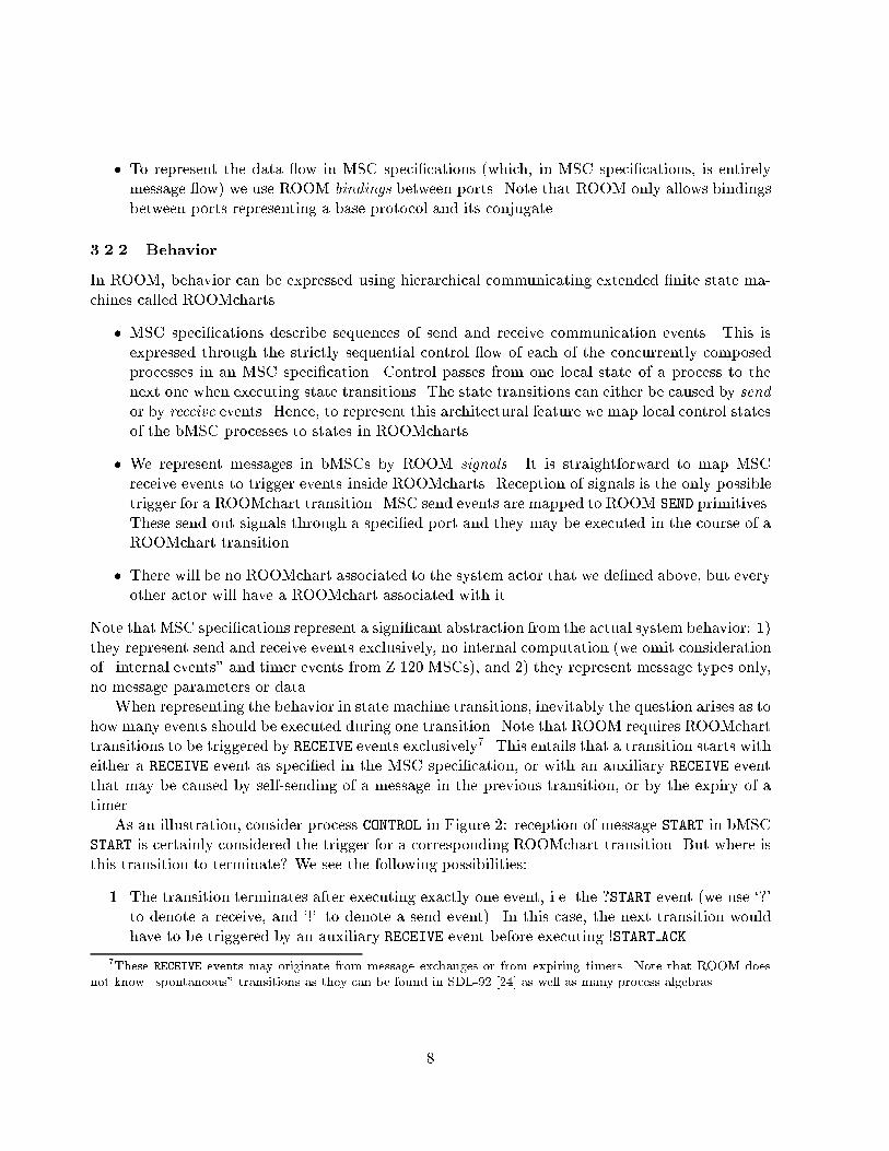
hierarchical state machine structure, the synthesized ROOMcharts will be at. One ROOMchartper process in the MSC speci�cation will be generated, see Figure 10. The maximum progressin every process will be di�erent, hence the corresponding state machines will not have identicalstructure.The algorithm proceeds in three steps. For each process Pi the following steps will be performed:1. A graph of all messages contained in all bMSCs for which Pi is either a sender or a receiver isbuilt. The graph is called the message graph reminiscent of the ne components of the message ow graphs in [20]. The nodes of the graph are similar to items of the message list (ML) ofthe previous algorithm. However, the message graph covers more than one bMSC and maybe iterating and branching as determined by the HMSC graph. The message graph imposes atotal order for all communication events and de�nes the causal relation amongst them. Thisconstruction is similar to the \unfolding" construction described for iterating and branchingMessage Flow Graphs in [20].2. The message graph of a process is used to �nd a set of traces (T = t1; t2; :::; tk). Eachmember of T, tk = (SourceState; T ransition;Action;DestinationState). The members ofT collectively describe all the states (SourceState and DestinationStates) that a processcan be in, transitions (Transition) which take it from a state to another, and all the actions(Action) that the transitions may cause. The transitions and actions correspond to the receiveand send events respectively. A transition (receive message) may cause sending of zero, oneor more messages.(a) The process Pi is initially assumed to be in state S0. The subsequent states are numberedincreasingly unless it is an old state (corresponding to a loop in the message graph).The �rst transition is the default transition which is de�ned for all ROOMcharts andis called Initialize. If the �rst message in the message graph is a receive message, thedefault transition (Initialize) will have no action associated with it. In this case the�rst trace will be t1 = (S0; Initialize;Null; S1) indicating that the �rst trace is fromstate S0 to state S1, which are connected by transition Initialize which causes no action(Null). While the message processed is not a receive, the �rst transition (Initialize) isused to send messages as its action. For example, the Initialize transition in the topROOMchart of User and Heating in Figure 10 will cause them to go state to S1 and waitfor the next message Comreq and Cool, respectively. Whereas, the Initialize transitionof actor Control results in sending of Comreq and Cool messages.(b) For every receive message, a new trace is written with the corresponding receive messageas its transition. The action items of the trace are found by searching the message treedepth-�rst to �nd all the send messages which are caused by this receive message. Thesearch is continued till for every succeeding branch a receive message is encountered.All the send messages found in the meanwhile are assigned as the action items of thetransition being processed.3. The Trace set T is converted to ROOM speci�cation. State S0 is translated into the initialpoint in the ROOMchart. The subsequent state elements (SourceState andDestinationStates)of the trace are used to create new states for the ROOMchart. Similarly, Transition and17
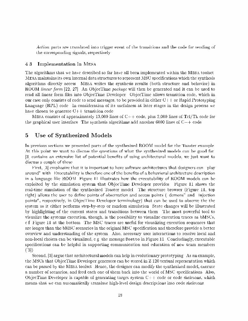
Action parts are translated into trigger event of the transitions and the code for sending ofthe corresponding signals, respectively.4.3 Implementation in MesaThe algorithms that we have described so far have all been implemented within the Mesa toolset.Mesamaintains its own internal data structures to represent MSC speci�cations which the synthesisalgorithms directly access. Mesa writes the synthesis results (both structure and behavior) inROOM linear form [22, 27]. An ObjecTime package will then be generated and it can be used toread all linear form �les into ObjecTime Developer. ObjecTime allows transition code, which inour case only consists of code to send messages, to be provided in either C++ or Rapid PrototypingLanguage (RPL) code. In consideration of its usefulness at later stages in the design process wehave chosen to generate C++ transition code.Mesa consists of approximately 13,000 lines of C++ code, plus 2,000 lines of Tcl/Tk code forthe graphical user interface. The synthesis algorithms add another 6000 lines of C++ code.5 Use of Synthesized ModelsIn previous sections we presented parts of the synthesized ROOM model for the Toaster example.At this point we want to discuss the questions of what the synthesized models can be good for.[3] contains an extensive list of potential bene�ts of using architectural models, we just want todiscuss a couple of these.First, [3] emphasize that it is important to have software architectures that designers can \playaround" with. Executability is therefore one of the bene�ts of a behavioral architecture descriptionin a language like ROOM. Figure 11 illustrates how the executability of ROOM models can beexploited by the simulation system that ObjecTime Developer provides. Figure 11 shows thereal-time simulation of the synthesized Toaster model. The structure browser (Figure 11, topright) allows the user to de�ne points of observation and access points (\demons" and \injectionpoints", respectively, in ObjecTime Developer terminology) that can be used to observe the thesystem as it either performs step-by-step or random simulation. State changes will be illustratedby highlighting of the current states and transitions between them. The most powerful tool tovisualize the systems execution, though, is the possibility to visualize execution traces as bMSCs,c.f. Figure 11 at the bottom. The MSC traces are useful for visualizing execution sequences thatare longer than the bMSC scenarios in the original MSC speci�cation and therefore provide a betteroverview and understanding of the system. Also, necessary user interactions to resolve local andnon-local choices can be visualized, e.g. the message Dostto in Figure 11. Concludingly, executablespeci�cations can be helpful in supporting communication and education of new team members([3]).Second, [3] argue that architectural models can help in evolutionary prototyping. As an example,the MSCs that ObjecTime Developer generates can be stored in Z.120 textual representation whichcan be parsed by theMesa toolset. Hence, the designer can modify the synthesized model, executea number of scenarios, and feed each one of them back into the world of MSC speci�cations. Also,ObjecTime Developer is capable of generating target system C++ code or code skeletons, whichmeans that we can automatically translate high-level design descriptions into code skeletons.18
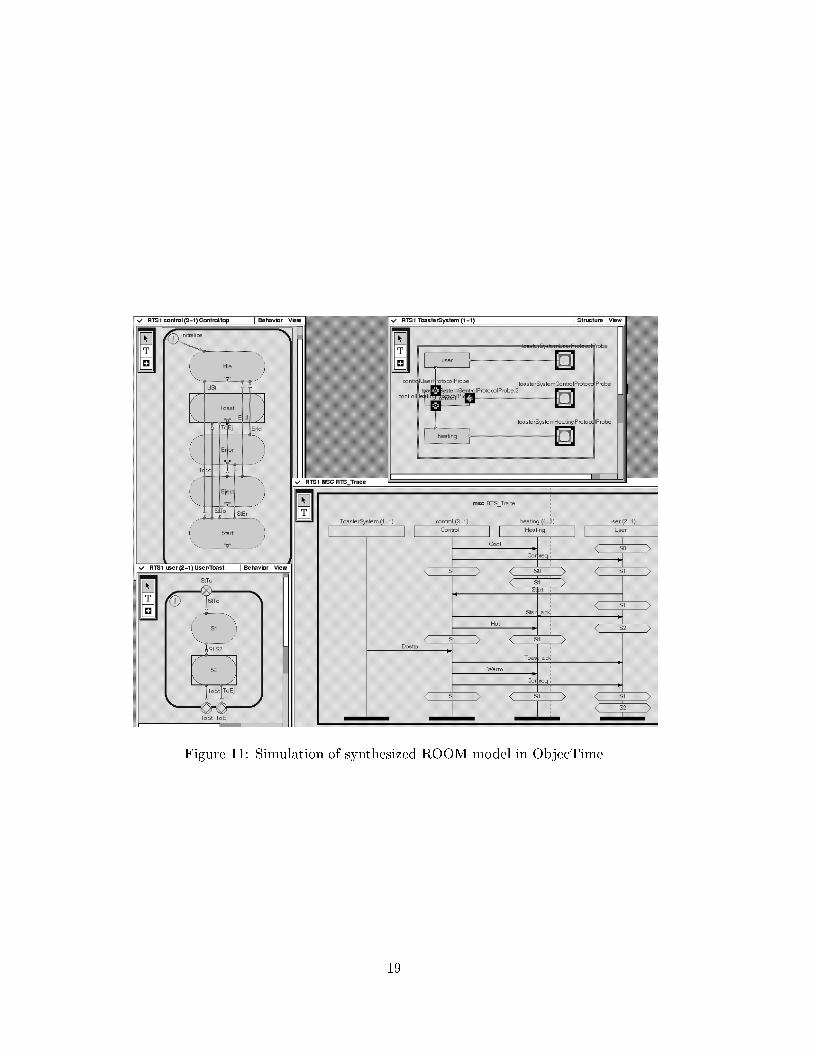
Figure 11: Simulation of synthesized ROOM model in ObjecTime
19
6 A complex example: GSM Mobility ManagementTo test the applicability of our algorithms and their implementation we have used the speci�cationof a GSM (Global Systems for Mobile communications) Mobility Management protocol [23]. Themobility management in GSM keeps track of the mobile while on the move. Figure 12 showsa generic architecture layout of the GSM. The system consists of four main parts, MS (MobileStation), BSS (Base Station Subsystem), MSC (Mobile services Switching Center) and Network.The MS is the portable unit used by the subscribers. The BBS controls the radio link with the MS.The MSC is part of the network subsystem but is separated from the rest of network to emphasisits role in the mobility management. The MSC manages the switching of calls between the mobileand other �xed or mobile network users. The Network in this example refers to the rest of thenetwork which may consist of other land-based or mobile networks.Mobile Station
MS
BBS
BBS
MSC(PSTN), ISDN, ...
Telephony Network
Public Switched
Base Station Subsytem Mobile service Switching Center Network
. . .
. . .
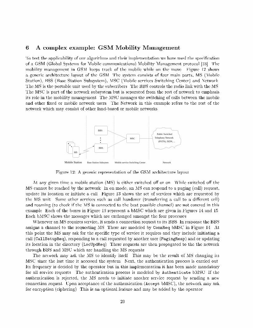
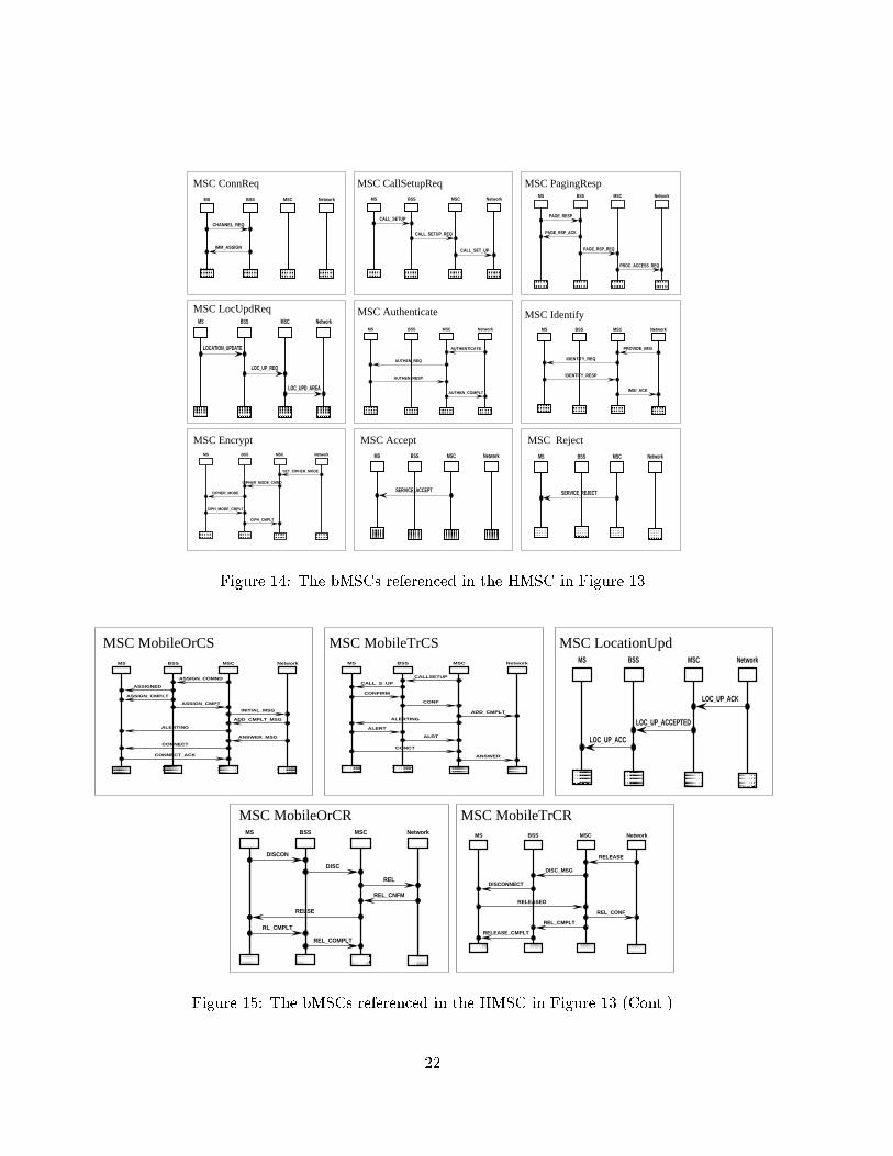
Figure 12: A generic representation of the GSM architecture layoutAt any given time a mobile station (MS) is either switched o� or on. While switched o� theMS cannot be reached by the network. In on mode, an MS can respond to a paging (call) request,update its location or initiate a call. Figure 13 shows the set of services which are requested bythe MS unit. Some other services such as call handover (transferring a call to a di�erent cell)and roaming (to check if the MS is connected to the best possible channel) are not covered in thisexample. Each of the boxes in Figure 13 represent a bMSC which are given in Figures 14 and 15.Each bMSC shows the messages which are exchanged amongst the four processes.Whenever an MS requires service, it sends a connection request to its BBS. In response the BBSassigns a channel to the requesting MS. These are modeled by ConnReq bMSC in Figure 14. Atthis point the MS may ask for the speci�c type of service it requires and they include initiating acall (CallSetupReq), responding to a call requested by another user (PagingResp) and or updatingits location in the directory (LocUpdReq). These requests are then propagated to the the networkthrough BBS and MSC which are handling the MS requests.The network may ask the MS to identify itself. This may be the result of MS changing itsMSC since the last time it accessed the system. Next, the authentication process is carried out.Its frequency is decided by the operator but in this implementation it has been made mandatoryfor all service requests. The authentication process is modeled by Authenticate bMSC. If theauthentication is rejected, the MS needs to initiate another service request by sending a newconnection request. Upon acceptance of the authentication (Accept bMSC), the network may askfor encryption (ciphering). This is an optional feature and may be added by the operator.20
ConnReq
Authenticate
Encrypt
Identify
PagingResp LocUpdReqCallSetupReq
Accept Reject
MobileTrCSMobileOrCS LocationUpd
MobileTrCRMobileOrCR
Figure 13: The HMSC speci�cation of mobility management in a GSM network21
MS BSS MSC Network
CHANNEL_REQ
IMM_ASSIGN
MS BSS MSC Network
CALL_SETUP
CALL_SETUP_REQ
CALL_SET_UP
MS BSS MSC Network
PAGE_RESP
PAGE_RSP_ACK
PAGE_RSP_REQ
PROC_ACCESS_REQ
MS BSS MSC Network
LOCATION_UPDATE
LOC_UPD_AREA
LOC_UP_REQ
MS BSS MSC Network
AUTHENTICATE
AUTHEN_COMPLT
AUTHEN_REQ
AUTHEN_RESP
MS BSS MSC Network
IDENTITY_REQ
IDENTITY_RESP
IMSI_ACK
PROVIDE_IMSI
MS BSS MSC Network
SERVICE_REJECT
MS BSS MSC Network
SERVICE_ACCEPT
MS BSS MSC Network
CIPHER_MODE
CIPHER_MODE_CMND
CIPH_CMPLT
CIPH_MODE_CMPLT
SET_CIPHER_MODE
MSC ConnReq MSC CallSetupReq MSC PagingResp
MSC LocUpdReq MSC Authenticate MSC Identify
MSC RejectMSC AcceptMSC Encrypt
Figure 14: The bMSCs referenced in the HMSC in Figure 13MS BSS MSC Network
ADD_CMPLT
ALERT
ALERTING
ALRT
ANSWER
CALLSETUP
CALL_S_UP
CONCT
CONF
CONFIRM
MS BSS MSC Network
LOC_UP_ACC
LOC_UP_ACCEPTED
LOC_UP_ACK
MS BSS MSC Network
DISCONNECT
DISC_MSG
RELEASE
RELEASED
RELEASE_CMPLT
REL_CMPLT
REL_CONF
MS BSS MSC Network
DISC
DISCON
REL
RELSE
REL_CNFM
REL_COMPLT
RL_CMPLT
MS BSS MSC Network
ADD_CMPLT_MSG
ALERTING
ANSWER_MSG
ASSIGNED
ASSIGN_CMPLT
ASSIGN_CMPT
ASSIGN_COMND
CONNECT
CONNECT_ACK
INITIAL_MSG
MSC LocationUpd
MSC MobileTrCR
MSC MobileOrCS MSC MobileTrCS
MSC MobileOrCR
Figure 15: The bMSCs referenced in the HMSC in Figure 13 (Cont.)22
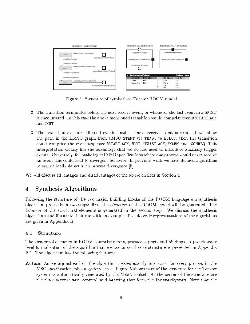
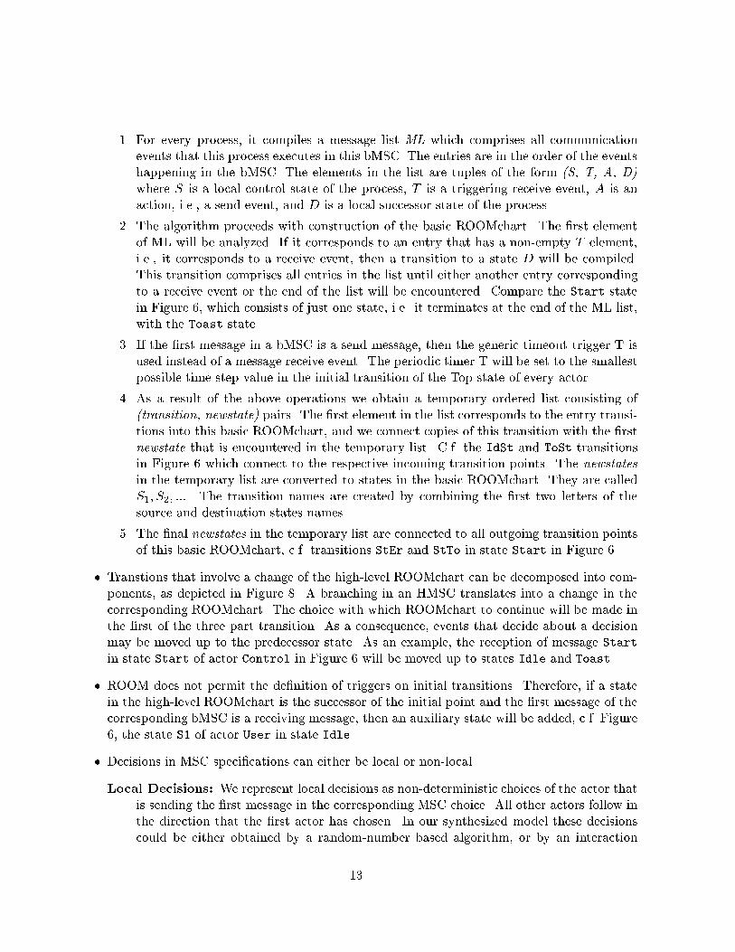
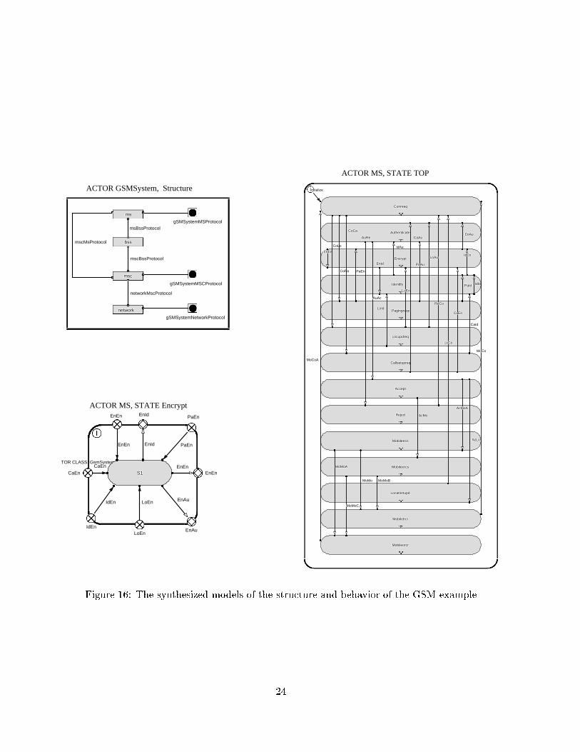
The three bMSCs after Accept bMSC correspond to the acceptance of the network of therequests which were initiated by the MS at the beginning. For example if the MS had requesteda location update LocUpdReq, the network after successful completion of identi�cation (optional),encryption (optional) and authentication processes, would respond by initiating the LocationUpdbMSC. Similarly, MobileOrCS (mobile originated call setup) and MobileTrCS (mobile terminatedcall setup) bMSCs are initiated by the network in response to the CallSetupReq and PagingResprespectively.Once a call is completed, it can be terminated at the request of the MS user or the other party.These are represented by the MobileOrCR (mobile originated call release) and MobileTrCR (mobileterminated call release), respectively.The Synthesized ModelThe structural synthesis algorithm produces �ve actors (four corresponding to MSC processes andone system actor) and seven protocols (four for the coordination relation in the MSC speci�cationand three for injection points). The structure of the system actor GsmSystem is shown in Figure16. It contains the other four actors and their bindings.The maximum progress algorithm synthesizes the system behavior and creates four ROOM-charts. The ROOMchart for the MS actor has 11 states and 20 transitions. The ROOMcharts forBBS, MSC and Network actors have 9 states and 16 transitions, 17 states and 27 transitions, and5 states and 15 transitions, respectively.The maximum traceability algorithm produces identical top ROOMchart for all actors. Thesetop ROOMcharts each have 14 states corresponding bMSCs in the HMSC and 32 transitions forthe edges connecting the bMSC nodes. Figure 16 shows the top ROOMchart for the MS actor.Additionally, each actor has a number of states and transitions in its subROOMcharts. The sub-ROOMcharts for MS, BSS, MSC and Network actors have 22 states and 71 transitions, 20 statesand 69 transitions, 24 states and 79 transitions, and 18 states and 67 transitions, respectively.The di�erence between the number of states and transitions produced by the two algorithmsare quite signi�cant. The additional number of states and transitions created by the maximumtraceability algorithm is the trade o� for preserving the hierarchical information contained in theMSC speci�cation.7 ConclusionSummary. We presented algorithms which extract structural and behavioral architecture infor-mation from ITU-T Z.120 MSC speci�cations. The architectural information is represented in theADL ROOM. The structural part mainly represents the concurrent processes and their commu-nication relationship. For the behavioral part we have suggested two variants for the analysis:the maximum traceability algorithm, which emphasizes preservation of the HMSC structure in thestate space of the synthesized model, and the maximum progress algorithm, which provides moresuccinct state machines but sacri�ces traceability with respect to the HMSC graph. The algorithmshave been implemented in theMesa toolset that we are currently developing. Finally, we discussedaspects of the practical use of the synthesized models in the software design process. Overall, ourwork contributes to making Z.120 MSC speci�cations more useful in the Software design process.23
MobileorcrMobileorcrMobileorcrMobileorcrMobileorcrMobileorcrMobileorcrMobileorcrMobileorcr
MobiletrcrMobiletrcrMobiletrcrMobiletrcrMobiletrcrMobiletrcrMobiletrcrMobiletrcrMobiletrcr
LocationupdLocationupdLocationupdLocationupdLocationupdLocationupdLocationupdLocationupdLocationupd
MobileorcsMobileorcsMobileorcsMobileorcsMobileorcsMobileorcsMobileorcsMobileorcsMobileorcs
MobiletrcsMobiletrcsMobiletrcsMobiletrcsMobiletrcsMobiletrcsMobiletrcsMobiletrcsMobiletrcs
RejectRejectRejectRejectRejectRejectRejectRejectReject
AcceptAcceptAcceptAcceptAcceptAcceptAcceptAcceptAccept
CallsetupreqCallsetupreqCallsetupreqCallsetupreqCallsetupreqCallsetupreqCallsetupreqCallsetupreqCallsetupreq
LocupdreqLocupdreqLocupdreqLocupdreqLocupdreqLocupdreqLocupdreqLocupdreqLocupdreq
PagingrespPagingrespPagingrespPagingrespPagingrespPagingrespPagingrespPagingrespPagingresp
IdentifyIdentifyIdentifyIdentifyIdentifyIdentifyIdentifyIdentifyIdentify
EncryptEncryptEncryptEncryptEncryptEncryptEncryptEncryptEncrypt
AuthenticateAuthenticateAuthenticateAuthenticateAuthenticateAuthenticateAuthenticateAuthenticateAuthenticate
ConnreqConnreqConnreqConnreqConnreqConnreqConnreqConnreqConnreq
initializeinitializeinitializeinitializeinitializeinitializeinitializeinitializeinitialize
MoCoAMoCoAMoCoAMoCoAMoCoAMoCoAMoCoAMoCoAMoCoA
MoCoMoCoMoCoMoCoMoCoMoCoMoCoMoCoMoCo
LoCoLoCoLoCoLoCoLoCoLoCoLoCoLoCoLoCo
MoMoBMoMoBMoMoBMoMoBMoMoBMoMoBMoMoBMoMoBMoMoB
MoMoCMoMoCMoMoCMoMoCMoMoCMoMoCMoMoCMoMoCMoMoC
MoMoMoMoMoMoMoMoMoMoMoMoMoMoMoMoMoMo
MoMoAMoMoAMoMoAMoMoAMoMoAMoMoAMoMoAMoMoAMoMoA
ReCoReCoReCoReCoReCoReCoReCoReCoReCo
AcLoAcLoAcLoAcLoAcLoAcLoAcLoAcLoAcLo
AcMoAAcMoAAcMoAAcMoAAcMoAAcMoAAcMoAAcMoAAcMoA
AcMoAcMoAcMoAcMoAcMoAcMoAcMoAcMoAcMo
CaAuCaAuCaAuCaAuCaAuCaAuCaAuCaAuCaAu
CaEnCaEnCaEnCaEnCaEnCaEnCaEnCaEnCaEn
CaIdCaIdCaIdCaIdCaIdCaIdCaIdCaIdCaId
LoAuLoAuLoAuLoAuLoAuLoAuLoAuLoAuLoAu
LoIdLoIdLoIdLoIdLoIdLoIdLoIdLoIdLoId
LoEnLoEnLoEnLoEnLoEnLoEnLoEnLoEnLoEn
PaAuPaAuPaAuPaAuPaAuPaAuPaAuPaAuPaAu
PaEnPaEnPaEnPaEnPaEnPaEnPaEnPaEnPaEn
PaIdPaIdPaIdPaIdPaIdPaIdPaIdPaIdPaId IdIdIdIdIdIdIdIdIdIdIdIdIdIdIdIdIdId
IdAuIdAuIdAuIdAuIdAuIdAuIdAuIdAuIdAu
IdEnIdEnIdEnIdEnIdEnIdEnIdEnIdEnIdEn
EnAuEnAuEnAuEnAuEnAuEnAuEnAuEnAuEnAu
EnIdEnIdEnIdEnIdEnIdEnIdEnIdEnIdEnId
EnEnEnEnEnEnEnEnEnEnEnEnEnEnEnEnEnEn
AuReAuReAuReAuReAuReAuReAuReAuReAuRe
AuAcAuAcAuAcAuAcAuAcAuAcAuAcAuAcAuAc
CoLoCoLoCoLoCoLoCoLoCoLoCoLoCoLoCoLo
CoPaCoPaCoPaCoPaCoPaCoPaCoPaCoPaCoPa
CoCaCoCaCoCaCoCaCoCaCoCaCoCaCoCaCoCa
msmsmsmsmsmsmsmsms
msBssProtocolmsBssProtocolmsBssProtocolmsBssProtocolmsBssProtocolmsBssProtocolmsBssProtocolmsBssProtocolmsBssProtocol
bssbssbssbssbssbssbssbssbss
mscBssProtocolmscBssProtocolmscBssProtocolmscBssProtocolmscBssProtocolmscBssProtocolmscBssProtocolmscBssProtocolmscBssProtocol
mscmscmscmscmscmscmscmscmsc
networkMscProtocolnetworkMscProtocolnetworkMscProtocolnetworkMscProtocolnetworkMscProtocolnetworkMscProtocolnetworkMscProtocolnetworkMscProtocolnetworkMscProtocol
mscMsProtocolmscMsProtocolmscMsProtocolmscMsProtocolmscMsProtocolmscMsProtocolmscMsProtocolmscMsProtocolmscMsProtocol
networknetworknetworknetworknetworknetworknetworknetworknetwork
gSMSystemMSCProtocolgSMSystemMSCProtocolgSMSystemMSCProtocolgSMSystemMSCProtocolgSMSystemMSCProtocolgSMSystemMSCProtocolgSMSystemMSCProtocolgSMSystemMSCProtocolgSMSystemMSCProtocol
gSMSystemMSProtocolgSMSystemMSProtocolgSMSystemMSProtocolgSMSystemMSProtocolgSMSystemMSProtocolgSMSystemMSProtocolgSMSystemMSProtocolgSMSystemMSProtocolgSMSystemMSProtocol
gSMSystemNetworkProtocolgSMSystemNetworkProtocolgSMSystemNetworkProtocolgSMSystemNetworkProtocolgSMSystemNetworkProtocolgSMSystemNetworkProtocolgSMSystemNetworkProtocolgSMSystemNetworkProtocolgSMSystemNetworkProtocol
-- ACTOR CLASS: GsmSystem
S1S1S1S1S1S1S1S1S1
IdEnIdEnIdEnIdEnIdEnIdEnIdEnIdEnIdEn LoEnLoEnLoEnLoEnLoEnLoEnLoEnLoEnLoEn
PaEnPaEnPaEnPaEnPaEnPaEnPaEnPaEnPaEn
CaEnCaEnCaEnCaEnCaEnCaEnCaEnCaEnCaEn
EnEnEnEnEnEnEnEnEnEnEnEnEnEnEnEnEnEn
EnEnEnEnEnEnEnEnEnEnEnEnEnEnEnEnEnEn
EnAuEnAuEnAuEnAuEnAuEnAuEnAuEnAuEnAu
EnIdEnIdEnIdEnIdEnIdEnIdEnIdEnIdEnId
EnEnEnEnEnEnEnEnEnEnEnEnEnEnEnEnEnEn
IdEnIdEnIdEnIdEnIdEnIdEnIdEnIdEnIdEnLoEnLoEnLoEnLoEnLoEnLoEnLoEnLoEnLoEn
EnAuEnAuEnAuEnAuEnAuEnAuEnAuEnAuEnAu
PaEnPaEnPaEnPaEnPaEnPaEnPaEnPaEnPaEn
CaEnCaEnCaEnCaEnCaEnCaEnCaEnCaEnCaEn
EnEnEnEnEnEnEnEnEnEnEnEnEnEnEnEnEnEn EnIdEnIdEnIdEnIdEnIdEnIdEnIdEnIdEnId
ACTOR GSMSystem, Structure
ACTOR MS, STATE TOP
ACTOR MS, STATE Encrypt
Figure 16: The synthesized models of the structure and behavior of the GSM example24
Future research. The synthesis algorithms have been formalized, and their formalization can befound in Appendix A. However, we currently rely on an intuitive understanding of their functioningand have no proof of properties that they preserve. A formal investigation of this aspect is an openissue. Furthermore, we need to further investigate the use of the generated ROOM models inthe design process, including guidelines for further re�nement transformations. It should �nallybe noted that while we have found ROOM to be a very suitable design notation, our work is inprinciple also applicable to other, similar notations, like UML, UML-RT and SDL.Acknowledgements. We wish to thank Bran Selic for constructive criticism on an earlier versionof this work. Financial support for this research was provided by: ObjecTime Limited, Commu-nications and Information Technology Ontario (CITO), and the Natural Sciences and EngineeringResearch Council (NSERC) of Canada.
25
References[1] B. Algayres, Y. Lejeune, F. Hugonment, and F. Hantz. The AVALON project: a validation environmentfor SDL/MSC descriptions. In O. Faergemand and A. Sarma, editors, Proceedings of the 6th SDL Forum,SDL'93: Using Objects, October 1993.[2] R. Alur, G. J. Holzmann, and D. Peled. An analyzer for message sequence charts. In T. Margaria andB. Ste�en, editors, Tools and Algorithms for the Construction and Analysis of Systems, Lecture Notesin Computer Science, Vol. 1055, pages 35{48. Springer Verlag, 1996.[3] L. Bass, P. Clements, and R. Kazman. Software Architecture in Practice. Addison Wesley Longman,1998.[4] H. Ben-Abdallah and S. Leue.Mesa: Support for scenario-based design of concurrent systems. TechnicalReport 97-12, Department of Electrical & Computer Engineering, University of Waterloo, October 19971997. 17 p.[5] H. Ben-Abdallah and S. Leue. Syntactic detection of process divergence and non-local choice in messagesequence charts. In E. Brinksma, editor, Tools and Algorithms for the Construction and Analysis ofSystems, Lecture Notes in Computer Science, Vol. 1217, pages 259{274. Springer Verlag, 1997.[6] H. Ben-Abdallah and S. Leue. Timing constraints in message sequence chart speci�cations. In T.Mizuno, N. Shiratori, T. Higashino, and A. Togashi, editors, Formal Description Techniques and Pro-tocol Speci�cation, Testing and Veri�cation, FORTE X / PSTV XVII '97, pages 91 { 106. Chapman &Hall, November 1997.[7] H. Ben-Abdallah and S. Leue. Mesa: Support for scenario-based design of concurrent systems. InB. Ste�en, editor, Tools and Algorithms for the Construction and Analysis of Systems, Proceedings ofthe 4th International Conference, volume 1384 of Lecture Notes in Computer Science, pages 118 { 135.Springer Verlag, 1998.[8] R.J.A. Buhr and C.S. Casselman. Use Case Maps for Object-Oriented Systems. Prentice Hall, 1996.[9] Rational Software Corporation. UML notation guide. Research report, 1997. See alsohttp://www.rational.com/uml. Also The Object Management Group, document number ad/07-08-05.[10] R. Delon. Implementation in mesa of the PROMELA code generator. E&CE 499 Project Report,Univesity of Waterloo, April 1998.[11] A. Engels, S. Mauw, and M. Reniers. A hierarchy of communication models for message sequence charts.In T. Mizuno, N. Shiratori, T. Higashino, and A. Togashi, editors, Formal Description Techniques andProtocol Speci�cation, Testing and Veri�cation, FORTE X/PSTV XVII '97, pages 75 { 90. Chapman& Hall, November 1997.[12] G. J. Holzmann. What's new in SPIN version 2.0. http://netlib.att.com/netlib/spin/index.html. VersionApril 17, 1996.[13] G. J. Holzmann. Early fault detection tools. In T. Margaria and B. Ste�en, editors, Tools and Algorithmsfor the Construction and Analysis of Systems, Lecture Notes in Computer Science, Vol. 1055, pages1{13. Springer Verlag, 1996.[14] H. Ichikawa, M. Itoh, J. Kato, A. Takura, and M. Shibasaki. SDE: Incremental speci�cation anddevelopment of communications software. IEEE Transactions on Computers, 40(4):553{561, Apr. 1991.[15] ITU-T. Recommendation Z.120. ITU - Telecommunication Standardization Sector, Geneva, Switzer-land, May 1996. Review Draft Version. 26
[16] I. Jacobson and et al. Object-Oriented Software Engineering - A Use-case Driven Approach. Addison-Wesley, 1992.[17] Kai Koskimies, Tatu M�annist�o, Tarja Syst�a, and Jyrki Tuomi. On the role of scenarios in object-orientedsoftware design. In Lars Bendix, Kurt Normark, and Kasper Osterbye, editors, Proceedings of the NordicWorkshop on Programming Environment Research, Aalborg, May 29-31, 1996. Aalborg University. pub-lished as WWW-URL http://www.cs.auc.dk/ normark/NWPER96/proceedings/proceedings.html.[18] Kai Koskimies, Tarja Syst�a, Jyrki Tuomi, and Tatu M�annist�o. Automated support for modeling OOsoftware. IEEE Software, 15(1):87{94, January-February 1998.[19] P. B. Ladkin and S. Leue. Four issues concerning the semantics of Message Flow Graphs. In D. Hogrefeand S. Leue, editors, Formal Description Techniques, VII, Proceedings of the Seventh InternationalConference on Formal Description Techniques. Chapman & Hall, 1995.[20] P. B. Ladkin and S. Leue. Interpreting Message Flow Graphs. Formal Aspects of Computing, 7(5):473{509, 1995.[21] S. Leue and P. B. Ladkin. Implementing and verifying scenario-based speci�cations usingPromela/XSpin. In J.-C. Gr�egoire, G. J. Holzmann, and D. A. Peled, editors, Proceedings of the2nd Workshop on the SPIN Veri�cation System, Rutgers University, August 5, 1996. American Math-ematical Society, DIMACS/32, 1997.[22] ObjecTime Limited. ObjecTime Toolset Guide, Document Version 1.0 for ObjecTime Developer 5.1,August 1997.[23] Asha Mehrotra. GSM System Engineering, chapter 4. Artech House Publishers, Norwood, MA, 1996.[24] A. Olsen, O. F�rgemand, B. M�ller-Pedersen, R. Reed, and J.R.W. Smith. Systems Engineering UsingSDL-92. Elsevier Science B.V. (North-Holland), 1994.[25] J. Rumbaugh, M. Blaha, W. Premerlani, F. Eddy, and W. Lorensen. Object-Oriented Modeling andDesign. Prentice Hall International, 1991.[26] B. Selic. Automatic generation of test drivers from MSC specs. Technical Report TR 960514 - Rev. 01,ObjecTime Limited, Kanata, Ontario, Canada, 1996.[27] B. Selic, G. Gullekson, and P.T. Ward. Real-Time Object-Oriented Modelling. John Wiley & Sons, Inc.,1994.[28] B. Selic and J. Rumbaugh. Using UML for modeling complex real-time systems.www.objectime.com/new/uml/index.html, March 1998.[29] S. Som�e, R. Dssouli, and J. Vaucher. From scenarios to timed automata: Building speci�cations fromuser requirements. In Proceedings of the 2nd Asia Paci�c Software Engineering Conference. IEEE,December 1995.
27
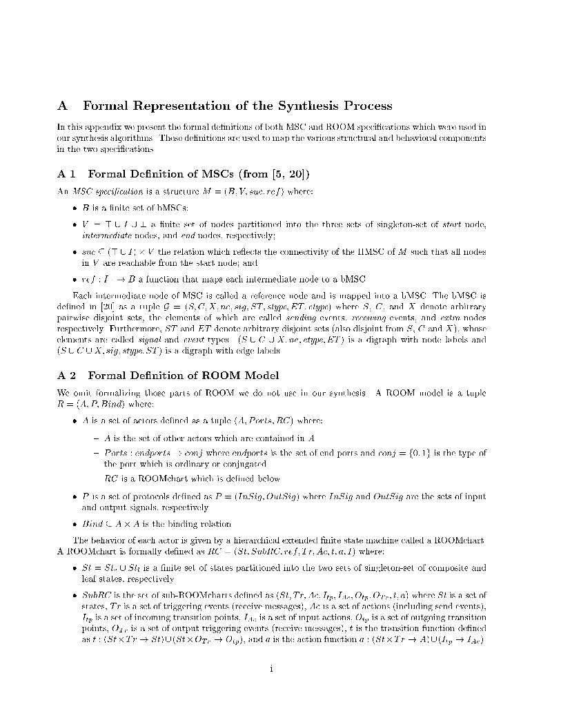
A Formal Representation of the Synthesis ProcessIn this appendix we present the formal de�nitions of both MSC and ROOM speci�cations which were used inour synthesis algorithms. These de�nitions are used to map the various structural and behavioral componentsin the two speci�cations.A.1 Formal De�nition of MSCs (from [5, 20])An MSC speci�cation is a structure M = (B; V; suc; ref) where:� B is a �nite set of bMSCs;� V = > [ I [ ? a �nite set of nodes partitioned into the three sets of singleton-set of start node,intermediate nodes, and end nodes, respectively;� suc � (>[ I)� V the relation which re ects the connectivity of the HMSC of M such that all nodesin V are reachable from the start node; and� ref : I 7�! B a function that maps each intermediate node to a bMSC.Each intermediate node of MSC is called a reference node and is mapped into a bMSC. The bMSC isde�ned in [20] as a tuple G = (S;C;X; ne; sig; ST; stype; ET; etype) where S, C, and X denote arbitrarypairwise disjoint sets, the elements of which are called sending events, receiving events, and extra nodesrespectively. Furthermore, ST and ET denote arbitrary disjoint sets (also disjoint from S, C and X), whoseelements are called signal and event types. (S [ C [ X;ne; etype; ET ) is a digraph with node labels and(S [ C [X; sig; stype; ST ) is a digraph with edge labels.A.2 Formal De�nition of ROOM ModelWe omit formalizing those parts of ROOM we do not use in our synthesis. A ROOM model is a tupleR = (A;P;Bind) where:� A is a set of actors de�ned as a tuple (A;Ports; RC) where:{ A is the set of other actors which are contained in A.{ Ports : endports! conj where endports is the set of end ports and conj = f0; 1g is the type ofthe port which is ordinary or conjugated.{ RC is a ROOMchart which is de�ned below.� P is a set of protocols de�ned as P = (InSig;OutSig) where InSig and OutSig are the sets of inputand output signals, respectively.� Bind � A�A is the binding relation.The behavior of each actor is given by a hierarchical extended �nite state machine called a ROOMchart.A ROOMchart is formally de�ned as RC = (St; SubRC; ref; T r; Ac; t; a; I) where:� St = Stc [ Stl is a �nite set of states partitioned into the two sets of singleton-set of composite andleaf states, respectively.� SubRC is the set of sub-ROOMcharts de�ned as (St; T r; Ac; Itp; IAc; Otp; OTr; t; a) where St is a set ofstates, Tr is a set of triggering events (receive messages), Ac is a set of actions (including send events),Itp is a set of incoming transition points, IAc is a set of input actions, Otp is a set of outgoing transitionpoints, OTr is a set of output triggering events (receive messages), t is the transition function de�nedas t : (St�Tr ! St)[ (St�OTr ! Otp), and a is the action function a : (St�Tr ! A)[ (Itp ! IAc).i
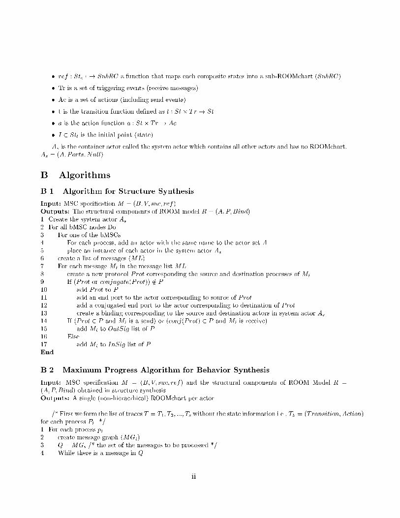
� ref : Stc 7�! SubRC a function that maps each composite states into a sub-ROOMchart (SubRC).� Tr is a set of triggering events (receive messages).� Ac is a set of actions (including send events).� t is the transition function de�ned as t : St� Tr ! St.� a is the action function a : St� Tr ! Ac.� I 2 Stl is the initial point (state).As is the container actor called the system actor which contains all other actors and has no ROOMchart,As = (A;Ports;Null).B AlgorithmsB.1 Algorithm for Structure SynthesisInput: MSC speci�cation M = (B; V; suc; ref).Outputs: The structural components of ROOM model R = (A;P;Bind).1. Create the system actor As2. For all bMSC nodes Do3. For one of the bMSCs4. For each process, add an actor with the same name to the actor set A5. place an instance of each actor in the system actor As6. create a list of messages (ML)7. For each message Mi in the message list ML8. create a new protocol Prot corresponding the source and destination processes of Mi9. If (Prot or conjugate(Prot)) =2 P10. add Prot to P11. add an end port to the actor corresponding to source of Prot12. add a conjugated end port to the actor corresponding to destination of Prot13. create a binding corresponding to the source and destination actors in system actor As14. If (Prot 2 P and Mi is a send) or (conj(Prot) 2 P and Mi is receive)15. add Mi to OutSig list of P16. Else17. add Mi to InSig list of PEndB.2 Maximum Progress Algorithm for Behavior SynthesisInput: MSC speci�cation M = (B; V; suc; ref) and the structural components of ROOM Model R =(A;P;Bind) obtained in structure synthesis.Outputs: A single (non-hieracrhical) ROOMchart per actor./* First we form the list of traces T = T1; T2; :::; Ts without the state information i.e., Tk = (Transition;Action)for each process Pi. */1. For each process pi2. create message graph (MGi)3. Q =MGi /* the set of the messages to be processed */4. While there is a message in Q ii
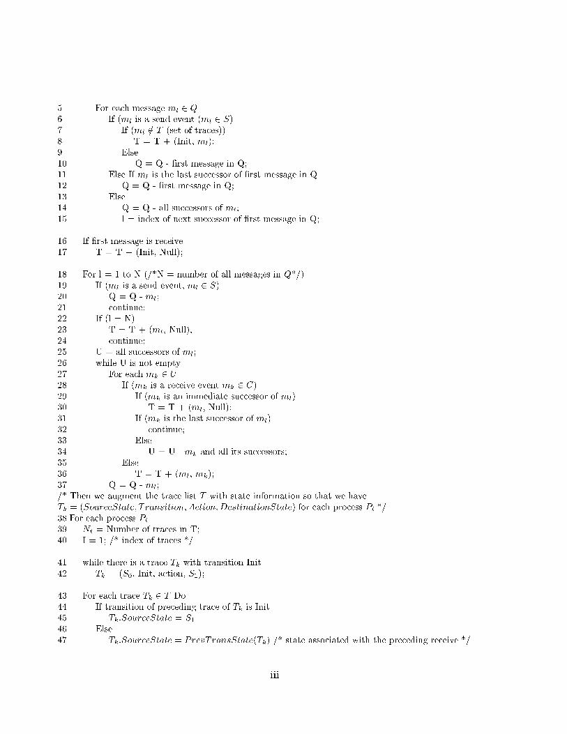
5. For each message ml 2 Q6. If (ml is a send event (ml 2 S)7. If (ml =2 T (set of traces))8 . T = T + (Init, ml);9. Else10. Q = Q - �rst message in Q;11. Else If ml is the last successor of �rst message in Q12. Q = Q - �rst message in Q;13. Else14. Q = Q - all successors of ml;15. l = index of next successor of �rst message in Q;16. If �rst message is receive17. T = T + (Init, Null);18. For l = 1 to N (/*N = number of all messages in Q*/)19. If (ml is a send event, ml 2 S)20. Q = Q - ml;21. continue;22. If (l = N)23. T = T + (ml, Null);24. continue;25. U = all successors of ml;26. while U is not empty27. For each mk 2 U28. If (mk is a receive event mk 2 C)29. If (mk is an immediate successor of ml)30. T = T + (ml, Null);31. If (mk is the last successor of ml)32. continue;33. Else34. U = U - mk and all its successors;35. Else36. T = T + (ml, mk);37. Q = Q - ml;/* Then we augment the trace list T with state information so that we haveTk = (SourceState; T ransition;Action;DestinationState) for each process Pi.*/38.For each process Pi39. Nt = Number of traces in T;40. I = 1; /* index of traces */41. while there is a trace Tk with transition Init42. Tk = (S0, Init, action, S1);43. For each trace Tk 2 T Do44. If transition of preceding trace of Tk is Init45. Tk:SourceState = S146. Else47. Tk:SourceState = PrevTransState(Tk) /* state associated with the preceding receive */iii
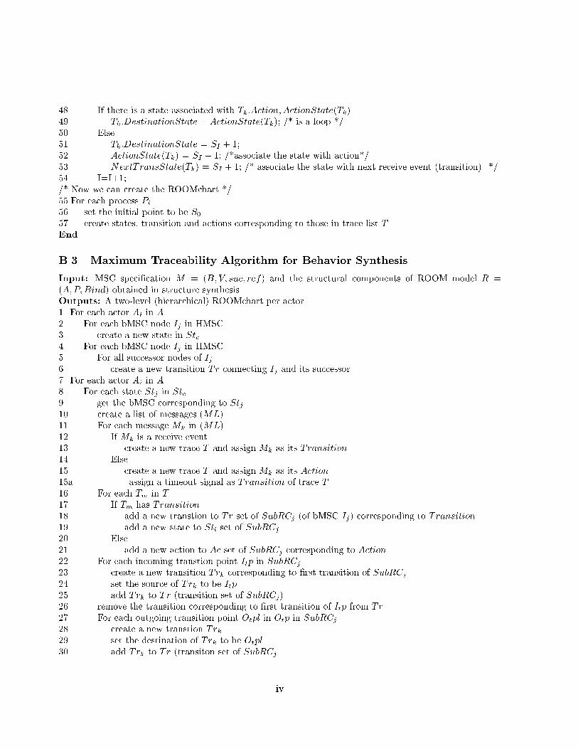
48. If there is a state associated with Tk:Action;ActionState(Tk)49. Tk:DestinationState = ActionState(Tk); /* is a loop */50. Else51. Tk:DestinationState = SI + 1;52. ActionState(Tk) = SI + 1; /*associate the state with action*/53. NextTransState(Tk) = SI + 1; /* associate the state with next receive event (transition). */54. I=I+1;/* Now we can create the ROOMchart */55.For each process Pi56. set the initial point to be S057. create states, transition and actions corresponding to those in trace list TEndB.3 Maximum Traceability Algorithm for Behavior SynthesisInput: MSC speci�cation M = (B; V; suc; ref) and the structural components of ROOM model R =(A;P;Bind) obtained in structure synthesis.Outputs: A two-level (hierarchical) ROOMchart per actor.1. For each actor Ai in A2. For each bMSC node Ij in HMSC3. create a new state in Stc4. For each bMSC node Ij in HMSC5. For all successor nodes of Ij6. create a new transition Tr connecting Ij and its successor7. For each actor Ai in A8. For each state Stj in Stc9. get the bMSC corresponding to Stj10. create a list of messages (ML)11. For each message Mk in (ML)12. If Mk is a receive event13. create a new trace T and assign Mk as its Transition14. Else15. create a new trace T and assign Mk as its Action15a. assign a timeout signal as Transition of trace T16. For each Tm in T17. If Tm has Transition18. add a new transtion to Tr set of SubRCj (of bMSC Ij) corresponding to Transition19. add a new state to Stl set of SubRCj20. Else21. add a new action to Ac set of SubRCj corresponding to Action22. For each incoming transtion point Itp in SubRCj23. create a new transition Trk corresponding to �rst transition of SubRCj24. set the source of Trk to be Itp25. add Trk to Tr (transition set of SubRCj)26. remove the transition corresponding to �rst transition of Itp from Tr27. For each outgoing transition point Otpl in Otp in SubRCj28. create a new transtion Trk29. set the destination of Trk to be Otpl30. add Trk to Tr (transiton set of SubRCjiv
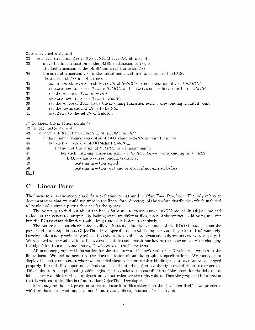
31.For each actor Ai in A32. For each transition Trk in Tr of ROOMchart RC of actor Ai33. move the �rst transition of the bMSC destination of Trk to. the last transition of the bMSC source of transition Trk34. If source of transition Trk is the Initial point and �rst transition of the bMSC. destination of Trk is not a timeout35. add a new state Stlk in state set Stl of SubRC of the destination of Trk (SubRCn)36. create a new transition Trm in SubRCn and make it same as �rst transition in SubRCn37. set the source of Trm to be Stlk38. create a new transition Trm2 in SubRCn39. set the source of Trm2 to be the incoming transition point corresponding to initial point40. set the destination of Trm2 to be Stlk41. add Trm2 to the set Tr of SubRCn/* To assign the injection points */42.For each actor Ai in A43. For each subROOMchart SubRCk of ROOMchart RC44. If the number of successors of subROOMchart SubRCk is more than one45. For each successor subROOMchart SubRCm46. I� the �rst transition of SubRCm is a timeout signal47. For each outgoing transition point of SubRCk, Otpm corresponding to SubRCk48. If Otpm has a corresponding transition49. create an injection signal50. create an injection port and protocol if not existed beforeEndC Linear FormThe linear form is the storage and data exchange format used in ObjecTime Developer. The only referencedocumentation that we could use were in the linear form directory of the toolset distribution which includeda lex �le and a simple parser that checks the syntax.The best way to �nd out about the linear form was to create simple ROOM models in ObjecTime andto look at the generated output. By looking at many di�erent �les, most of the syntax could be �gured outbut the ROOMchart de�nition took a long time as it is done recursively.The parser does not check name con icts. Names de�ne the semantics of the ROOM model. Thus theparser did not complain but ObjecTime Developer did not read the input created by Mesa. Unfortunately,Developer does not provide any information about the possible problems and only syntax errors are displayed.We assumed name con icts to be the reason i.e. states and transitions having the same name. After changingthe algorithm to avoid same names, Developer read the linear form.All necessary graphical information for the structure and behavior editor in Developer is written in thelinear form. We had no access to the documentation about the graphical speci�cations. We managed todisplay the states and actors where we intended them to be but neither bindings nor transitions are displayedproperly. Instead, Developer uses default values and puts the objects at the right end of the states or actors.This is due to a complicated graphic engine that calculates the coordinates of the boxes for the labels. Aslabels have variable lengths, our algorithm cannot calculate the right values. Thus the graphical informationthat is written in the �les is of no use for ObjecTime Developer.Mesamay be the �rst program to create linear form �les other than the Developer itself. Two problemswhich we have observed but have not found reasonable explanations for them are:v
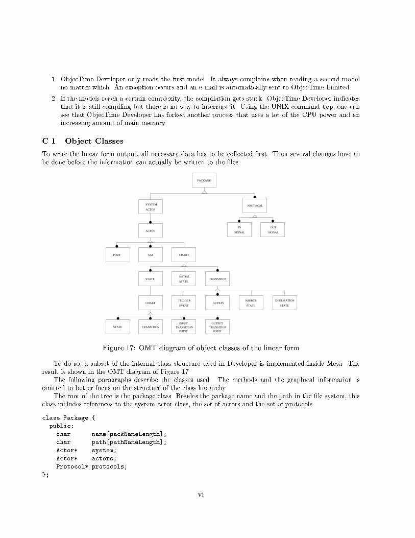
1. ObjecTime Developer only reads the �rst model. It always complains when reading a second modelno matter which. An exception occurs and an e-mail is automatically sent to ObjecTime Limited.2. If the models reach a certain complexity, the compilation gets stuck. ObjecTime Developer indicatesthat it is still compiling but there is no way to interrupt it. Using the UNIX command top, one cansee that ObjecTime Developer has forked another process that uses a lot of the CPU power and anincreasing amount of main memory.C.1 Object ClassesTo write the linear form output, all necessary data has to be collected �rst. Then several changes have tobe done before the information can actually be written to the �les.PACKAGE
PROTOCOL
IN
SIGNAL
OUT
SIGNAL
SAP CHARTPORT
STATEINITIAL
STATETRANSITION
ACTOR
SYSTEM
ACTOR
EVENT STATE
STATE
CHARTTRIGGER
ACTIONSOURCE DESTINATION
STATE
TRANSITION
POINTTRANSITION
INPUT
POINTTRANSITION
OUTPUTFigure 17: OMT diagram of object classes of the linear formTo do so, a subset of the internal class structure used in Developer is implemented inside Mesa. Theresult is shown in the OMT diagram of Figure 17.The following paragraphs describe the classes used. The methods and the graphical information isomitted to better focus on the structure of the class hierarchy.The root of the tree is the package class. Besides the package name and the path in the �le system, thisclass includes references to the system actor class, the set of actors and the set of protocols.class Package {public:char name[packNameLength];char path[pathNameLength];Actor* system;Actor* actors;Protocol* protocols;}; vi
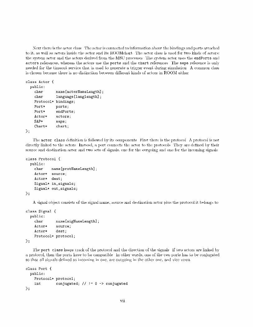
Next there is the actor class. The actor is connected to information about the bindings and ports attachedto it, as well as actors inside the actor and its ROOMchart. The actor class is used for two kinds of actors:the system actor and the actors derived from the MSC processes. The system actor uses the endPorts andactors references, whereas the actors use the ports and the chart references. The saps reference is onlyneeded for the timeout service that is used to generate a trigger event during simulation. A common classis chosen because there is no distinction between di�erent kinds of actors in ROOM either.class Actor {public:char name[actorNameLength];char language[langlength];Protocol* bindings;Port* ports;Port* endPorts;Actor* actors;SAP* saps;Chart* chart;}; The actor class de�nition is followed by its components. First there is the protocol. A protocol is notdirectly linked to the actors. Instead, a port connects the actor to the protocols. They are de�ned by theirsource and destination actor and two sets of signals, one for the outgoing and one for the incoming signals.class Protocol {public:char name[protNameLength];Actor* source;Actor* dest;Signal* in_signals;Signal* out_signals;}; A signal object consists of the signal name, source and destination actor plus the protocol it belongs to.class Signal {public:char name[sigNameLength];Actor* source;Actor* dest;Protocol* protocol;}; The port class keeps track of the protocol and the direction of the signals. If two actors are linked bya protocol, then the ports have to be compatible. In other words, one of the two ports has to be conjugatedso that all signals de�ned as incoming in one, are outgoing in the other one, and vice versa.class Port {public:Protocol* protocol;int conjugated; // != 0 -> conjugated}; vii
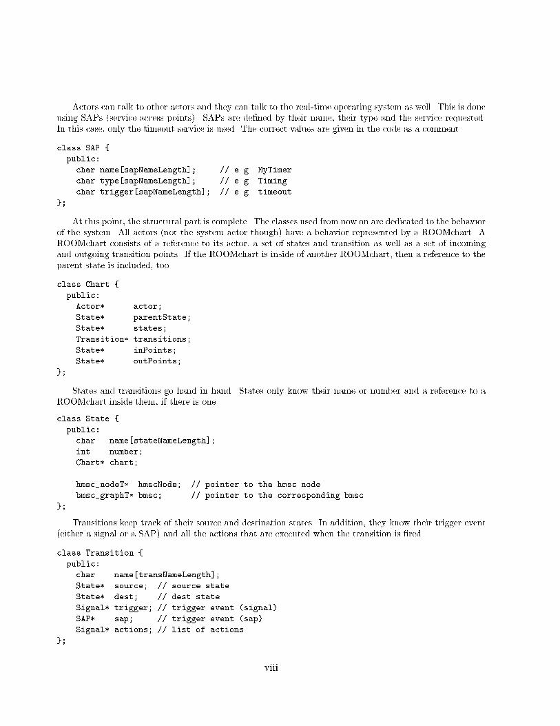
Actors can talk to other actors and they can talk to the real-time operating system as well. This is doneusing SAPs (service access points). SAPs are de�ned by their name, their type and the service requested.In this case, only the timeout service is used. The correct values are given in the code as a comment.class SAP {public:char name[sapNameLength]; // e.g. MyTimerchar type[sapNameLength]; // e.g. Timingchar trigger[sapNameLength]; // e.g. timeout}; At this point, the structural part is complete. The classes used from now on are dedicated to the behaviorof the system. All actors (not the system actor though) have a behavior represented by a ROOMchart. AROOMchart consists of a reference to its actor, a set of states and transition as well as a set of incomingand outgoing transition points. If the ROOMchart is inside of another ROOMchart, then a reference to theparent state is included, too.class Chart {public:Actor* actor;State* parentState;State* states;Transition* transitions;State* inPoints;State* outPoints;}; States and transitions go hand in hand. States only know their name or number and a reference to aROOMchart inside them, if there is one.class State {public:char name[stateNameLength];int number;Chart* chart;hmsc_nodeT* hmscNode; // pointer to the hmsc nodebmsc_graphT* bmsc; // pointer to the corresponding bmsc}; Transitions keep track of their source and destination states. In addition, they know their trigger event(either a signal or a SAP) and all the actions that are executed when the transition is �red.class Transition {public:char name[transNameLength];State* source; // source stateState* dest; // dest stateSignal* trigger; // trigger event (signal)SAP* sap; // trigger event (sap)Signal* actions; // list of actions}; viii
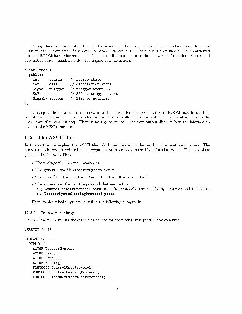
During the synthesis, another type of class is needed: the trace class. The trace class is used to createa list of signals extracted of the complex MSC data structure. The trace is then modi�ed and convertedinto the ROOMchart information. A single trace list item contains the following information: Source anddestination states (numbers only), the trigger and the actions.class Trace {public:int source; // source stateint dest; // destination stateSignal* trigger; // trigger event ORSAP* sap; // SAP as trigger eventSignal* actions; // list of actionsc}; Looking at the data structure, one can see that the internal representation of ROOM models is rathercomplex and redundant. It is therefore unavoidable to collect all data �rst, modify it and write it to thelinear form �les as a last step. There is no way to create linear form output directly from the informationgiven in the MSC structures.C.2 The ASCII �lesIn this section we explain the ASCII �les which are created as the result of the synthesis process. TheTOASTER model was introduced in the beginning of this report, is used here for illustration. The algorithmsproduce the following �les:� The package �le (Toaster.package)� The system actor �le (ToasterSystem.actor)� The actor �les (User.actor, Control.actor, Heating.actor)� The system port �les for the protocols between actors(e.g. ControlHeatingProtocol.port) and the protocols between the systemactor and the actors(e.g. ToasterSystemHeatingProtocol.port)They are described in greater detail in the following paragraphs.C.2.1 Toaster.packageThe package �le only lists the other �les needed for the model. It is pretty self-explaining.VERSION '1.1'PACKAGE ToasterPUBLIC {ACTOR ToasterSystem;ACTOR User;ACTOR Control;ACTOR Heating;PROTOCOL ControlUserProtocol;PROTOCOL ControlHeatingProtocol;PROTOCOL ToasterSystemUserProtocol; ix
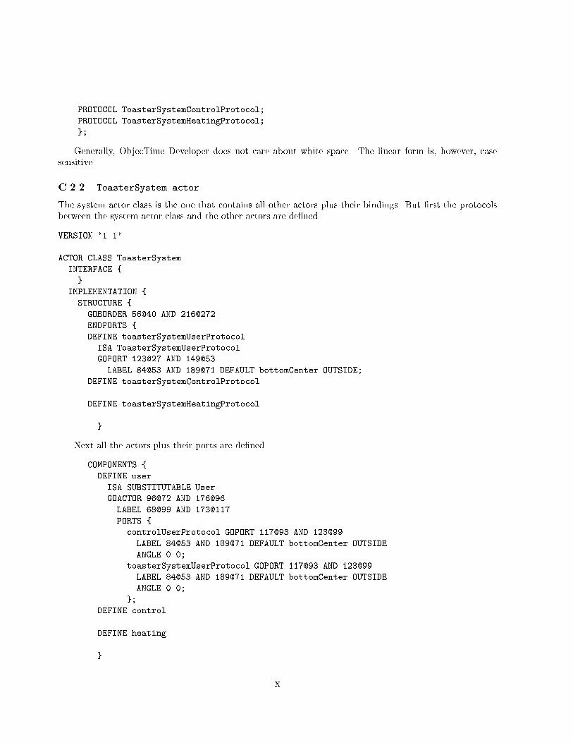
PROTOCOL ToasterSystemControlProtocol;PROTOCOL ToasterSystemHeatingProtocol;};Generally, ObjecTime Developer does not care about white space. The linear form is, however, casesensitive.C.2.2 ToasterSystem.actorThe system actor class is the one that contains all other actors plus their bindings. But �rst the protocolsbetween the system actor class and the other actors are de�ned.VERSION '1.1'ACTOR CLASS ToasterSystemINTERFACE {}IMPLEMENTATION {STRUCTURE {GOBORDER 56@40 AND 216@272ENDPORTS {DEFINE toasterSystemUserProtocolISA ToasterSystemUserProtocolGOPORT 123@27 AND 149@53LABEL 84@53 AND 189@71 DEFAULT bottomCenter OUTSIDE;DEFINE toasterSystemControlProtocol...DEFINE toasterSystemHeatingProtocol...}Next all the actors plus their ports are de�ned.COMPONENTS {DEFINE userISA SUBSTITUTABLE UserGOACTOR 96@72 AND 176@96LABEL 68@99 AND 173@117PORTS {controlUserProtocol GOPORT 117@93 AND 123@99LABEL 84@53 AND 189@71 DEFAULT bottomCenter OUTSIDEANGLE 0.0;toasterSystemUserProtocol GOPORT 117@93 AND 123@99LABEL 84@53 AND 189@71 DEFAULT bottomCenter OUTSIDEANGLE 0.0;};DEFINE control...DEFINE heating...} x
The de�nition of the bindings is the next step. The prototocol name is followed by the name of the actor(if not the system actor).BINDINGS {DEFINE B1 [*] BETWEEN controlUserProtocol/controlAND controlUserProtocol/userGOBINDING 118@97 AND 123@120LABEL 111@99 AND 130@117FROM 120@99 TO 120@117;DEFINE B2 [*] BETWEEN controlHeatingProtocol/controlAND controlHeatingProtocol/heating...DEFINE B3 [*] BETWEEN toasterSystemUserProtocolAND toasterSystemUserProtocol/user...DEFINE B4 [*] BETWEEN toasterSystemControlProtocolAND toasterSystemControlProtocol/control...DEFINE B5 [*] BETWEEN toasterSystemHeatingProtocol...}}As a last step the behavior is de�ned. The system actor class has no behavior and therefore this sectionis almost empty.BEHAVIOR {LANGUAGE 'C++'FSMGOBORDER 56@40 AND 664@504}};C.2.3 Control.actorThe control actor �le is chosen as a representative of all actors. The linear form �le starts with the de�nitionof the interfaces.VERSION '1.1'ACTOR CLASS ControlINTERFACE {PORTS {DEFINE controlUserProtocolISA ControlUserProtocolGOPORT 123@27 AND 149@53LABEL 84@53 AND 189@71 DEFAULT bottomCenter OUTSIDEANGLE 0.0;DEFINE controlHeatingProtocol... xi
DEFINE toasterSystemControlProtocol...}}Next there is the de�ntion of the structure. As the interfaces have already been de�ned above, there isonly a reference to them in the de�nition of the endports.IMPLEMENTATION {STRUCTURE {GOBORDER 56@40 AND 216@176ENDPORTS {INTERFACE controlUserProtocol;INTERFACE controlHeatingProtocol;INTERFACE toasterSystemControlProtocol;}}The description of the behavior starts with the determination of the language (C++) and the de�nitionof the generic trigger. In this case a SAP called T of type Timing is used.BEHAVIOR {LANGUAGE 'C++'SAPS {DEFINE TISA Timing;}Next the FSMs (Finite State Machines) are de�ned. The 'maximum traceability' algorithm keeps thestructure of the MSCs and therefore de�nes a high-level FSM (in ROOM called ROOMcharts) and a set ofbasic FSMs inside the states of the high-level FSM.The linear form de�nes the transitions of the high-level FSM �rst. The only action that occurs is to setthe periodic timer T to 1. This will result in a signal T sent every simulation step.FSMGOBORDER 56@40 AND 328@552TRANSITIONS {DEFINE initializeFROM INITIALPOINTTO STATE Idle TRANSITION initializeGOFSMPOINT 141@173 AND 147@179 ANGLE 0.0GOTRANSITION 141@153 AND 148@177LABEL 138@132 AND 152@150 OFFSET 1@-24FROM 144@155 TO 144@173ACTION 'T.informEvery(1)';DEFINE IdStFROM STATE Idle TRANSITION IdSt STATE S1GOFSMPOINT 157@237 AND 163@203 ANGLE 0.0TO STATE Start TRANSITION IdStGOFSMPOINT 157@261 AND 163@227 ANGLE 0.0xii
GOTRANSITION 157@241 AND 164@225LABEL 154@220 AND 168@198 OFFSET 1@-24FROM 144@155 TO 144@173;DEFINE ToEj...}Next all states of the high-level ROOMchart are de�ned. As they all include a basic ROOMchart, this isde�ned as well. The order of the de�nition is again transitions �rst and substates next but this time withoutfurther ROOMcharts inside .The de�nition of Error is chosen as it shows how to de�ne action with the send function of the protocoland the de�nition of the trigger event either using a message of a protocol or the SAP T.SUBSTATES {DEFINE Idle...DEFINE Toast...DEFINE ErrorGOSTATE 112@264 AND 272@328LABEL 0@0 AND 0@0GOBORDER 56@40 AND 264@288TRANSITIONS {DEFINE StErFROM BORDER TRANSITION StEr STATE StartGOFSMPOINT 141@149 AND 147@155 ANGLE 0.0TO STATE S1GOFSMPOINT 141@173 AND 147@179 ANGLE 0.0GOTRANSITION 141@153 AND 148@177LABEL 138@132 AND 152@150 OFFSET 1@-24FROM 144@155 TO 144@173ACTION 'controlUserProtocol.send(Empty)';DEFINE S1S2FROM STATE S1GOFSMPOINT 157@237 AND 163@203 ANGLE 0.0TO STATE S2...TRIGGERS {DEFINE SIGNALS {Reset} ON {controlUserProtocol};};DEFINE ErIdFROM STATE S2GOFSMPOINT 173@325 AND 179@251 ANGLE 0.0...TRIGGERS {DEFINE SIGNALS {timeout} ON {T};};}SUBSTATES {DEFINE S1 xiii
GOSTATE 112@0 AND 208@64LABEL 0@0 AND 0@0GOBORDER 56@40 AND 664@504;DEFINE S2GOSTATE 112@88 AND 208@152LABEL 0@0 AND 0@0GOBORDER 56@40 AND 664@504;};DEFINE Eject...DEFINE Start...}}};C.2.4 ControlUserProtocol.portNow one of the protocol �les between actors will be shown. The incoming and outgoing messages are listedin a self-explaining manner.VERSION '1.1'PROTOCOL CLASS ControlUserProtocolSERVICE BasicCommunicationIN MESSAGES {DEFINE Reset ISA Null;DEFINE Ready ISA Null;DEFINE Start ISA Null;}OUT MESSAGES {DEFINE Comreq ISA Null;DEFINE Toast_ack ISA Null;DEFINE Empty ISA Null;DEFINE Start_ack ISA Null;};C.2.5 ToasterSystemHeatingProtocol.portThis �le is one of the protocol �les between the system actor and an actor. The algorithm has taken thetransition label StEr and create a signal Doster that can be injected when a decision has to be made atthat point.VERSION '1.1'PROTOCOL CLASS ToasterSystemHeatingProtocolSERVICE BasicCommunicationIN MESSAGES {}OUT MESSAGES { xiv
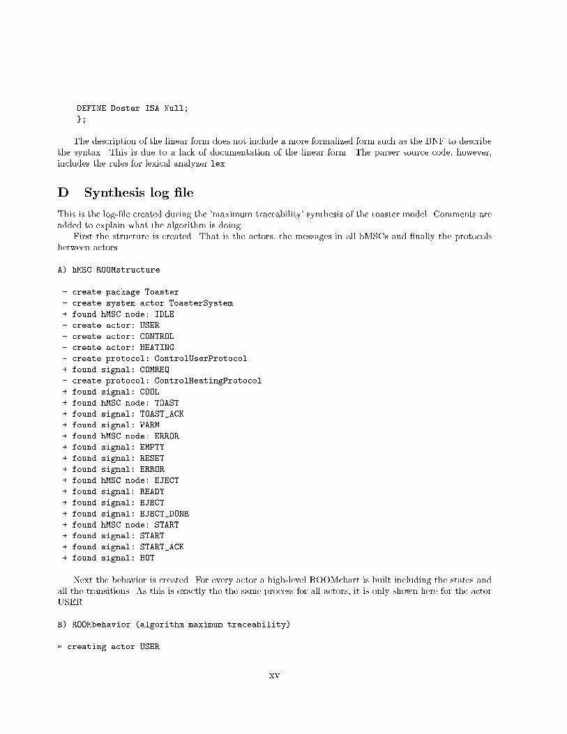
DEFINE Doster ISA Null;};The description of the linear form does not include a more formalized form such as the BNF to describethe syntax. This is due to a lack of documentation of the linear form. The parser source code, however,includes the rules for lexical analyzer lex.D Synthesis log �leThis is the log-�le created during the 'maximum traceability' synthesis of the toaster model. Comments areadded to explain what the algorithm is doing.First the structure is created. That is the actors, the messages in all bMSCs and �nally the protocolsbetween actors.A) hMSC ROOMstructure ...- create package Toaster- create system actor ToasterSystem+ found hMSC node: IDLE- create actor: USER- create actor: CONTROL- create actor: HEATING- create protocol: ControlUserProtocol+ found signal: COMREQ- create protocol: ControlHeatingProtocol+ found signal: COOL+ found hMSC node: TOAST+ found signal: TOAST_ACK+ found signal: WARM+ found hMSC node: ERROR+ found signal: EMPTY+ found signal: RESET+ found signal: ERROR+ found hMSC node: EJECT+ found signal: READY+ found signal: EJECT+ found signal: EJECT_DONE+ found hMSC node: START+ found signal: START+ found signal: START_ACK+ found signal: HOTNext the behavior is created. For every actor a high-level ROOMchart is built including the states andall the transitions. As this is exactly the the same process for all actors, it is only shown here for the actorUSER.B) ROOMbehavior (algorithm maximum traceability) ...* creating actor USER xv
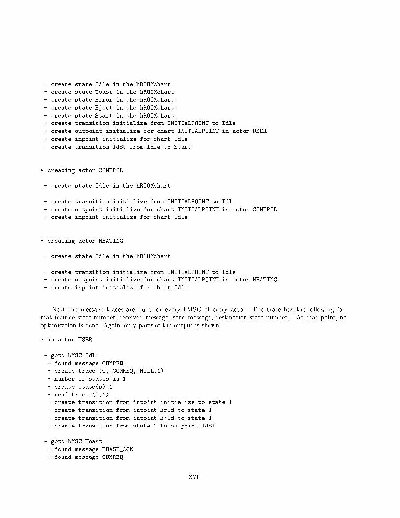
- create state Idle in the hROOMchart- create state Toast in the hROOMchart- create state Error in the hROOMchart- create state Eject in the hROOMchart- create state Start in the hROOMchart- create transition initialize from INITIALPOINT to Idle- create outpoint initialize for chart INITIALPOINT in actor USER- create inpoint initialize for chart Idle- create transition IdSt from Idle to Start...* creating actor CONTROL- create state Idle in the hROOMchart...- create transition initialize from INITIALPOINT to Idle- create outpoint initialize for chart INITIALPOINT in actor CONTROL- create inpoint initialize for chart Idle...* creating actor HEATING- create state Idle in the hROOMchart...- create transition initialize from INITIALPOINT to Idle- create outpoint initialize for chart INITIALPOINT in actor HEATING- create inpoint initialize for chart Idle...Next the message traces are built for every bMSC of every actor. The trace has the following for-mat (source state number, received message, send message, destination state number). At that point, nooptimization is done. Again, only parts of the output is shown.* in actor USER- goto bMSC Idle+ found message COMREQ- create trace (0, COMREQ, NULL,1)- number of states is 1- create state(s) 1- read trace (0,1)- create transition from inpoint initialize to state 1- create transition from inpoint ErId to state 1- create transition from inpoint EjId to state 1- create transition from state 1 to outpoint IdSt- goto bMSC Toast+ found message TOAST_ACK+ found message COMREQ xvi
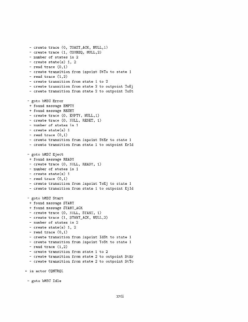
- create trace (0, TOAST_ACK, NULL,1)- create trace (1, COMREQ, NULL,2)- number of states is 2- create state(s) 1, 2- read trace (0,1)- create transition from inpoint StTo to state 1- read trace (1,2)- create transition from state 1 to 2- create transition from state 2 to outpoint ToEj- create transition from state 2 to outpoint ToSt- goto bMSC Error+ found message EMPTY+ found message RESET- create trace (0, EMPTY, NULL,1)- create trace (0, NULL, RESET, 1)- number of states is 1- create state(s) 1- read trace (0,1)- create transition from inpoint StEr to state 1- create transition from state 1 to outpoint ErId- goto bMSC Eject+ found message READY- create trace (0, NULL, READY, 1)- number of states is 1- create state(s) 1- read trace (0,1)- create transition from inpoint ToEj to state 1- create transition from state 1 to outpoint EjId- goto bMSC Start+ found message START+ found message START_ACK- create trace (0, NULL, START, 1)- create trace (1, START_ACK, NULL,2)- number of states is 2- create state(s) 1, 2- read trace (0,1)- create transition from inpoint IdSt to state 1- create transition from inpoint ToSt to state 1- read trace (1,2)- create transition from state 1 to 2- create transition from state 2 to outpoint StEr- create transition from state 2 to outpoint StTo* in actor CONTROL- goto bMSC Idle xvii
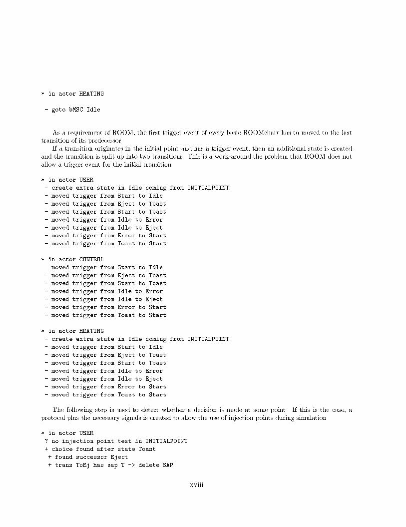
...* in actor HEATING- goto bMSC Idle...As a requirement of ROOM, the �rst trigger event of every basic ROOMchart has to moved to the lasttransition of its predecessor.If a transition originates in the initial point and has a trigger event, then an additional state is createdand the transition is split up into two transitions. This is a work-around the problem that ROOM does notallow a trigger event for the initial transition.* in actor USER- create extra state in Idle coming from INITIALPOINT- moved trigger from Start to Idle- moved trigger from Eject to Toast- moved trigger from Start to Toast- moved trigger from Idle to Error- moved trigger from Idle to Eject- moved trigger from Error to Start- moved trigger from Toast to Start* in actor CONTROL- moved trigger from Start to Idle- moved trigger from Eject to Toast- moved trigger from Start to Toast- moved trigger from Idle to Error- moved trigger from Idle to Eject- moved trigger from Error to Start- moved trigger from Toast to Start* in actor HEATING- create extra state in Idle coming from INITIALPOINT- moved trigger from Start to Idle- moved trigger from Eject to Toast- moved trigger from Start to Toast- moved trigger from Idle to Error- moved trigger from Idle to Eject- moved trigger from Error to Start- moved trigger from Toast to StartThe following step is used to detect whether a decision is made at some point. If this is the case, aprotocol plus the necessary signals is created to allow the use of injection points during simulation.* in actor USER? no injection point test in INITIALPOINT+ choice found after state Toast+ found successor Eject+ trans ToEj has sap T -> delete SAP xviii
- create protocol: ToasterSystemUserProtocol+ create signal DoToEj- add trigger DoToEj to transition ToEj+ found successor Start+ trans ToSt has sap T -> delete SAP+ create signal DoToSt- add trigger DoToSt to transition ToSt+ choice found after state Start+ found successor Error+ trans StEr has trigger Empty -> no injection needed+ found successor Toast+ trans StTo has trigger Toast_ack -> no injection needed* in actor CONTROL? no injection point test in INITIALPOINT+ choice found after state Toast+ found successor Eject+ trans ToEj has trigger Ready -> no injection needed+ found successor Start+ trans ToSt has trigger Start -> no injection needed+ choice found after state Start+ found successor Error+ trans StEr has trigger Error -> no injection needed+ found successor Toast+ trans StTo has sap T -> delete SAP- create protocol: ToasterSystemControlProtocol+ create signal DoStTo- add trigger DoStTo to transition StTo* in actor HEATING? no injection point test in INITIALPOINT+ choice found after state Toast+ found successor Eject+ trans ToEj has trigger Eject -> no injection needed+ found successor Start+ trans ToSt has trigger Hot -> no injection needed+ choice found after state Start+ found successor Error+ trans StEr has sap T -> delete SAP- create protocol: ToasterSystemHeatingProtocol+ create signal DoStEr- add trigger DoStEr to transition StEr+ found successor Toast+ trans StTo has trigger Warm -> no injection neededAs a last step all �les are written. The algorithm uses internal data structures to keep track of all theROOM model objects and names. Now this information is written to �les.- Writing file ./Toaster.package ... xix
- Writing file ./ToasterSystem.actor ...- Writing file ./ControlUserProtocol.port ...- Writing file ./ControlHeatingProtocol.port ...- Writing file ./ToasterSystemUserProtocol.port ...- Writing file ./ToasterSystemControlProtocol.port ...- Writing file ./ToasterSystemHeatingProtocol.port ...- Writing file ./User.actor ...- Writing file ./Control.actor ...- Writing file ./Heating.actor ...
xx


![article-Mesh Metho d for Shallo - Universiteit Utrechtfrank011/Articles/FrGoRe.pdf · 1 Hamiltonian P article-Mesh Metho d for Shallo wW ater Equations 3 (CASL) [4], semi-Lagrangian](https://img.pdfslide.us/doc/110x75/5d63206f88c993f37d8b55c0/article-mesh-metho-d-for-shallo-universiteit-frank011articlesfrgorepdf.jpg)

![A Generalized Forward Recovery Checkpointing Schemejiewu/research/publications/...of the most imp ortan t fault tolerance metho ds [1], [2], [3], [5], [7]. Basically, this metho d](https://img.pdfslide.us/doc/110x75/5ae2b5287f8b9a595d8d8aa0/a-generalized-forward-recovery-checkpointing-scheme-jiewuresearchpublicationsof.jpg)