Embed Size (px)
Citation preview
PRINTOUT MAY NOT BE UP-TO-DATE; REFER TO METRO INTRANET FOR THE LATEST VERSION
Engineering Specification Electrical Networks
MESP 040100-03
SIGNAL POWER SUPPLY TRANSFORMERS 3300/2200/110V AC 50Hz
Version: 2
Issued: October 2016
Owner: Chief Engineer
Approved By:
Andrew Russack
Head of Engineering - Electrical

SIGNAL POWER SUPPLY TRANSFORMERS 3300/2200/110V AC 50HZ
MESP 040100-03 Version: 2 Effective from 20th October 2016
L1-CHE-SPE-157
Approving Manager: Head of Engineering - Electrical Approval Date: 20/10/2016 Next Review Date: 20/10/2019 PRINTOUT MAY NOT BE UP-TO-DATE; REFER TO METRO INTRANET FOR THE LATEST VERSION Page 2 of 15
Approval
Amendment Record
Approval Date Version Description
20/07/2016 1 Initial issue under MTM.
20/10/2016 2
Three phase option removed. Tappings altered to include dual 3.3kV/2.2kV operation. Updates throughout.
This document supersedes VRIOGS 012.7.34.
SIGNAL POWER SUPPLY TRANSFORMERS 3300/2200/110V AC 50HZ
MESP 040100-03 Version: 2 Effective from 20th October 2016
L1-CHE-SPE-157
Approving Manager: Head of Engineering - Electrical Approval Date: 20/10/2016 Next Review Date: 20/10/2019 PRINTOUT MAY NOT BE UP-TO-DATE; REFER TO METRO INTRANET FOR THE LATEST VERSION Page 3 of 15
Table of Contents 1 Purpose ........................................................................................................................... 4 2 Scope ............................................................................................................................... 4 3 Abbreviations .................................................................................................................. 4 4 Definitions ....................................................................................................................... 4 5 References & Legislation ............................................................................................... 5
5.1 General ............................................................................................................................. 5 5.2 Standards .......................................................................................................................... 5
5.3 Legislation ......................................................................................................................... 6
5.4 MTM Documents ............................................................................................................... 6
6 Transformer .................................................................................................................... 6
6.1 General ............................................................................................................................. 6
6.2 Standard Sizing ................................................................................................................. 7
6.3 Windings ........................................................................................................................... 7
6.4 In-rush Current .................................................................................................................. 8 6.5 Noise ................................................................................................................................. 8
7 Ratings and Configuration ............................................................................................. 8 8 Construction ................................................................................................................... 9
8.1 General ............................................................................................................................. 9 8.2 Tappings and Terminals ................................................................................................... 9
8.3 Construction ...................................................................................................................... 9
8.4 Labelling .......................................................................................................................... 10
9 Testing ........................................................................................................................... 11
9.1 Type Test ........................................................................................................................ 11 9.2 Routine Tests .................................................................................................................. 11
9.3 Certificates ...................................................................................................................... 11
10 Other .............................................................................................................................. 12
10.1 Warranty ......................................................................................................................... 12
10.2 Maintainability ................................................................................................................. 12
10.3 Guaranteed Performance ............................................................................................... 12
11 Packaging and Delivery ................................................................................................ 13 12 Appendices ................................................................................................................... 13
Appendix 1: Details and Guaranteed Performance to be Supplied by Manufacturer ................... 14

SIGNAL POWER SUPPLY TRANSFORMERS 3300/2200/110V AC 50HZ
MESP 040100-03 Version: 2 Effective from 20th October 2016
L1-CHE-SPE-157
Approving Manager: Head of Engineering - Electrical Approval Date: 20/10/2016 Next Review Date: 20/10/2019 PRINTOUT MAY NOT BE UP-TO-DATE; REFER TO METRO INTRANET FOR THE LATEST VERSION Page 4 of 15
1 Purpose To define the requirements for the selection of indoor, dry type cast resin transformers for use in the Melbourne metropolitan railway signal power network. This specification covers transformers with a primary voltage of 3300V and 2200V and a secondary voltage of 110V.
2 Scope This Specification applies to the upgrade of existing signalling equipment and to all new signalling arrangements in the MTM network. It shall be utilised for the purchase of all 110V supply transformers connected to 2.2kV or 3.3kV signal power distribution systems. Such transformers may be located within trackside HV location boxes or indoor installations such as Power Equipment Room.
This specification supersedes VRIOGS 012.7.34.
3 Abbreviations AC Alternating Current
Hz Hertz
kV kilo Volt
MTM Metro Trains Melbourne Pty. Ltd.
V Voltage
VRIOGS Victorian Rail Industry Operators Group Standard
4 Definitions For all technical terms refer to AS 60076.
Dry-type Transformer
A transformer of which the magnetic circuit and windings are not immersed in an insulating liquid.
Essential Services A number of railway services considered essential to the running of trains or public safety including signalling and CCTV.
Primary Tapping The tapping to which the rated quantities are related.
Primary Winding The winding that receives the active power from the supply system, usually the winding having the highest rated voltage.
Secondary Winding The winding that delivers the active power to the load circuit, usually the winding having the lowest rated voltage.
Shall Is used as the descriptive word to express a requirement that is mandatory to achieve conformance to the standard.
Should Is used as the descriptive word to express a requirement that is recommended in order to achieve compliance to the standard. should can also be used if a requirement is a design goal but not a mandatory requirement.
SIGNAL POWER SUPPLY TRANSFORMERS 3300/2200/110V AC 50HZ
MESP 040100-03 Version: 2 Effective from 20th October 2016
L1-CHE-SPE-157
Approving Manager: Head of Engineering - Electrical Approval Date: 20/10/2016 Next Review Date: 20/10/2019 PRINTOUT MAY NOT BE UP-TO-DATE; REFER TO METRO INTRANET FOR THE LATEST VERSION Page 5 of 15
Signal Power Supply Transformer
A transformer that transforms the system voltages to a secondary voltage of nominally 110 V AC for the purpose of supplying power to the signalling circuits.
5 References & Legislation
5.1 General All materials and components shall comply with the relevant Australian Standard or, where these do not exist, with the relevant IEC or EN Standard.
Reference to all standards shall be read as a reference to the latest edition of that standard and amendments available at the time of tendering.
The transformer shall meet all relevant Environmental Acts, Legislation and Regulations, Codes of Practice and Standards, and shall be designed to minimise the impact on the environment. Accordingly the transformer shall minimise its environmental impact over its entire asset life cycle, including construction, ongoing operation and disposal. In particular, MTM has a focus on reduced electrical losses in its electrical systems.
5.2 Standards AS 1627.4 Metal finishing- Preparation and pre-treatment of surfaces Part 4:
Abrasive blast cleaning of steel.
AS 2067 Substations and high voltage installations exceeding 1kV AC
AS 2317 Collared Eyebolts
AS/NZS 2344 Limits of electromagnetic interference from overhead AC power lines and high voltage equipment installations in the range 0.15 to 1000 MHz
AS 2374.1.2 Power transformers Part 1.2: Minimum energy performance standard (MEPS) requirements for distribution transformers
AS 2374.2 Power transformers Part 2: Temperature rise.
AS 2374.5 Power transformers Part 5: Ability to withstand short-circuit.
AS 2629 Separable insulated connectors for power distribution systems above 1kV
AS 2700 Colour standards for general purposes
AS 3750.13 Paints for Steel Structures – Epoxy Primer (two packs)
AS 3750.10 Paints for Steel Structures – Full Gloss Epoxy (two packs)
AS/NZS 3750.15 Paints for steel structures Part 15: Inorganic zinc silicate paint.
AS 3953 Loading guide for dry-type power transformers.
AS/NZS 4680 Hot-dip galvanized (zinc) coatings on fabricated ferrous articles.
AS 60076.1 Power transformers Part 1: General.
AS 60076.4 Power transformers Part 4: Guide to the lightning impulse and switching impulse testing – Power transformers and reactors.
SIGNAL POWER SUPPLY TRANSFORMERS 3300/2200/110V AC 50HZ
MESP 040100-03 Version: 2 Effective from 20th October 2016
L1-CHE-SPE-157
Approving Manager: Head of Engineering - Electrical Approval Date: 20/10/2016 Next Review Date: 20/10/2019 PRINTOUT MAY NOT BE UP-TO-DATE; REFER TO METRO INTRANET FOR THE LATEST VERSION Page 6 of 15
AS/NZS 60076.10 Power transformers Part 10: Determination of sound levels.
AS 60076.11 Power transformers Part 11: Dry-type transformers.
AS/NZS 60137 Insulated bushings for alternating voltages above 1000V.
AS 60270 High Voltage test techniques – Partial discharge Measurements
AS 60529 Degrees of protection provided by enclosures (IP Code)
AS 62271.301 HV Switchgear and control gear – Dimensional standardisation of terminals
VRIOGS 012.1 Standard for Signalling Design and Documentation
VRIOGS 012.2 Specification of Signalling Supply, Construction and Installation
VRIOGS 012.7.9 Lightning and Surge Protection – General Requirements
VRIOGS 012.7.25 Environmental Conditions
VRIOGS 012.7.30 General Requirements for Labelling of Signalling Equipment
N/A PTV Infrastructure Drafting Standard
5.3 Legislation Compliance with the following legislation is mandatory.
Rail Safety Act 2006 (Victoria)
Occupational Health and Safety Act 2004 (Victoria)
Occupational Health and Safety Regulations 2007 (Victoria)
Electricity Safety Act 1998 (Victoria)
Electricity Safety (Installations) Regulations 2009 (Victoria)
5.4 MTM Documents L1-CHE-SPE-154 3.3kV Essential Services Distribution System
L1-CHE-SPE-150 Technical Specification for Automatic Control and Indicated Fixed Mounted Trackside Switchgear for Essential Services Purposes
6 Transformer
6.1 General 6.1.1 All transformers shall comply with the requirements of Australian Standards
AS60076; “Power Transformers” and AS 2374; “Minimum Energy Performance Standard (MEPS) requirements for distribution transformers”.
6.1.2 In general all transformers shall be natural air cooling type, with rated output specified, to operate with a temperature rise not exceeding 55°C. Non-metal clad types may be considered and shall provide suitable insulation protection to the HV and LV terminals. Refer Section 9.3 for details of the case for metal clad type.

SIGNAL POWER SUPPLY TRANSFORMERS 3300/2200/110V AC 50HZ
MESP 040100-03 Version: 2 Effective from 20th October 2016
L1-CHE-SPE-157
Approving Manager: Head of Engineering - Electrical Approval Date: 20/10/2016 Next Review Date: 20/10/2019 PRINTOUT MAY NOT BE UP-TO-DATE; REFER TO METRO INTRANET FOR THE LATEST VERSION Page 7 of 15
6.1.3 Transformers shall be designed for floor mounting inside an outdoor cubicle or within a building. Refer to MTM standard drawing STD_G0100 for details of the standard outdoor enclosure.
6.1.4 Details of environmental conditions can be found in VRIOGS 012.7.25 Rev A. The transformer shall be suitable for conditions described for classification B4.
6.2 Standard Sizing The transformer shall be one of the following standard capacities given in Table 1 below:
Table 1: 3300/110V transformer standard sizes
No. Rating (kVA)
1 3
2 6
3 10
4 15
5 20
In selecting from the standard capacities, the standing load shall not exceed 75% of the transformer capacity and the sum of transient load with the standard load shall not exceed 95% of the transformer capacity.
6.3 Windings 6.3.1 All transformers shall be provided with primary windings and secondary windings
with tappings as described in section 9.
6.3.2 Two tappings shall be provided on the primary winding – one for 2.2kV and one for 3.3kV.
6.3.3 Ten tappings shall be provided on the secondary winding at -2.5%, 0%, +2.5%, +5%, +7.5%, +10%, +12.5%, +15%, +17.5%, and +20% of the rated secondary voltage.
6.3.4 The winding connection should be as shown in and Figure 3 below. Alternative arrangements may be considered if justification is provided by the manufacturer.
P1 P2 P3
S1 S2 S3 S7
2200 1100
S6S5S4
Figure 1: Winding Configuration
SIGNAL POWER SUPPLY TRANSFORMERS 3300/2200/110V AC 50HZ
MESP 040100-03 Version: 2 Effective from 20th October 2016
L1-CHE-SPE-157
Approving Manager: Head of Engineering - Electrical Approval Date: 20/10/2016 Next Review Date: 20/10/2019 PRINTOUT MAY NOT BE UP-TO-DATE; REFER TO METRO INTRANET FOR THE LATEST VERSION Page 8 of 15
6.3.5 The tapping shall be achieved by means of multiple tap terminals, each of which shall have a continuous rating of 100% of the transformer full load current.
6.3.6 All insulation used in the transformers shall be non-hygroscopic and designed to withstand continuously a temperature of one hundred degrees centigrade.
6.3.7 After winding, the completed coils shall be thoroughly impregnated with an insulating compound under the vacuum process.
6.3.8 The composition of the insulating compound shall be such that it will not soften or ooze out under the continued exposure to the maximum working temperatures.
6.3.9 None of the materials used shall disintegrate under the continued action of heat and shall not carbonise, become brittle or lose their flexibility, with the maximum working temperatures.
6.4 In-rush Current The maximum inrush current of the transformers shall not exceed 8 times full load rated current.
6.5 Noise The transformer core shall be designed to limit the emanated noise from the transformer to the Reduced Maximum level as described in AS 60076.10.1:2009.
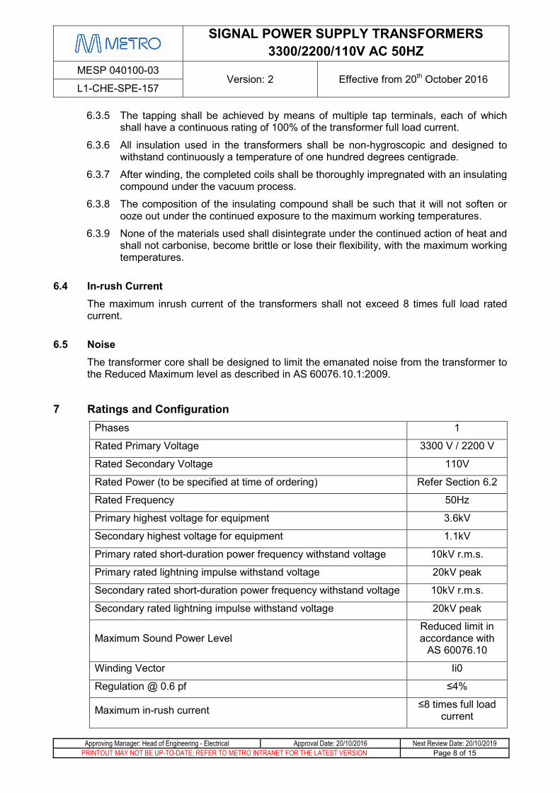
7 Ratings and Configuration Phases 1
Rated Primary Voltage 3300 V / 2200 V
Rated Secondary Voltage 110V
Rated Power (to be specified at time of ordering) Refer Section 6.2
Rated Frequency 50Hz
Primary highest voltage for equipment 3.6kV
Secondary highest voltage for equipment 1.1kV
Primary rated short-duration power frequency withstand voltage 10kV r.m.s.
Primary rated lightning impulse withstand voltage 20kV peak
Secondary rated short-duration power frequency withstand voltage 10kV r.m.s.
Secondary rated lightning impulse withstand voltage 20kV peak
Maximum Sound Power Level Reduced limit in accordance with
AS 60076.10
Winding Vector Ii0
Regulation @ 0.6 pf ≤4%
Maximum in-rush current ≤8 times full load current
SIGNAL POWER SUPPLY TRANSFORMERS 3300/2200/110V AC 50HZ
MESP 040100-03 Version: 2 Effective from 20th October 2016
L1-CHE-SPE-157
Approving Manager: Head of Engineering - Electrical Approval Date: 20/10/2016 Next Review Date: 20/10/2019 PRINTOUT MAY NOT BE UP-TO-DATE; REFER TO METRO INTRANET FOR THE LATEST VERSION Page 9 of 15
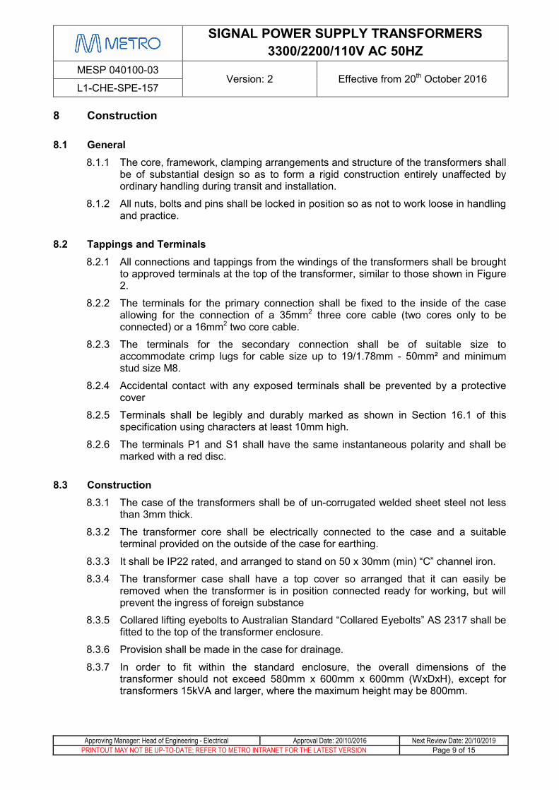
8 Construction
8.1 General 8.1.1 The core, framework, clamping arrangements and structure of the transformers shall
be of substantial design so as to form a rigid construction entirely unaffected by ordinary handling during transit and installation.
8.1.2 All nuts, bolts and pins shall be locked in position so as not to work loose in handling and practice.
8.2 Tappings and Terminals 8.2.1 All connections and tappings from the windings of the transformers shall be brought
to approved terminals at the top of the transformer, similar to those shown in Figure 2.
8.2.2 The terminals for the primary connection shall be fixed to the inside of the case allowing for the connection of a 35mm2 three core cable (two cores only to be connected) or a 16mm2 two core cable.
8.2.3 The terminals for the secondary connection shall be of suitable size to accommodate crimp lugs for cable size up to 19/1.78mm - 50mm² and minimum stud size M8.
8.2.4 Accidental contact with any exposed terminals shall be prevented by a protective cover
8.2.5 Terminals shall be legibly and durably marked as shown in Section 16.1 of this specification using characters at least 10mm high.
8.2.6 The terminals P1 and S1 shall have the same instantaneous polarity and shall be marked with a red disc.
8.3 Construction 8.3.1 The case of the transformers shall be of un-corrugated welded sheet steel not less
than 3mm thick.
8.3.2 The transformer core shall be electrically connected to the case and a suitable terminal provided on the outside of the case for earthing.
8.3.3 It shall be IP22 rated, and arranged to stand on 50 x 30mm (min) “C” channel iron.
8.3.4 The transformer case shall have a top cover so arranged that it can easily be removed when the transformer is in position connected ready for working, but will prevent the ingress of foreign substance
8.3.5 Collared lifting eyebolts to Australian Standard “Collared Eyebolts” AS 2317 shall be fitted to the top of the transformer enclosure.
8.3.6 Provision shall be made in the case for drainage.
8.3.7 In order to fit within the standard enclosure, the overall dimensions of the transformer should not exceed 580mm x 600mm x 600mm (WxDxH), except for transformers 15kVA and larger, where the maximum height may be 800mm.

SIGNAL POWER SUPPLY TRANSFORMERS 3300/2200/110V AC 50HZ
MESP 040100-03 Version: 2 Effective from 20th October 2016
L1-CHE-SPE-157
Approving Manager: Head of Engineering - Electrical Approval Date: 20/10/2016 Next Review Date: 20/10/2019 PRINTOUT MAY NOT BE UP-TO-DATE; REFER TO METRO INTRANET FOR THE LATEST VERSION Page 10 of 15
8.3.8 All metal surfaces shall be prepared in accordance with Australian Standard “Metal Finishing – Preparation and Pre-Treatment of Surfaces” AS 1627 prior to the application of protective primer to Australian Standard “Paints for Steel Structures – Epoxy Primer (two packs)” AS 3750.13.
8.3.9 The exterior of the transformer enclosure shall be painted in accordance with Australian Standard “Paints for Steel Structures – Full Gloss Epoxy (two packs)” AS 3750.10 and colour Y13 (vivid yellow) in accordance with Australian Standard “Colour Standards for General Purposes” AS 2700S.
Figure 2: Example of Typical Construction
8.4 Labelling 8.4.1 The transformer shall be provided with a rating plate complying with the
requirements of AS 60076.
8.4.2 The rating plate shall include the words “3300/2200/110V SIGNAL TRANSFORMER” and a table similar to Figure 3 to illustrate the tapping connections.
Connection Primary P1-P2 Volts Primary P1-P3 Volts Secondary Volts S2-S3
2200 3300
107.25 S1-S3 110 S2-S4 112.75 S1-S4 115.5 S2-S5 118.25 S1-S5 121 S2-S6 123.75 S1-S6 126.5 S2-S7 129.25 S1-S7 132
Figure 3: Typical Tapping Label

SIGNAL POWER SUPPLY TRANSFORMERS 3300/2200/110V AC 50HZ
MESP 040100-03 Version: 2 Effective from 20th October 2016
L1-CHE-SPE-157
Approving Manager: Head of Engineering - Electrical Approval Date: 20/10/2016 Next Review Date: 20/10/2019 PRINTOUT MAY NOT BE UP-TO-DATE; REFER TO METRO INTRANET FOR THE LATEST VERSION Page 11 of 15
8.4.3 The rating plate shall be constructed of stainless steel and shall be securely riveted to the top of the transformer. Recorded information shall be physically etched, embossed or engraved clearly onto the surface of the rating plate and shall be highlighted with black paint.
9 Testing
9.1 Type Test A Type Test Certificate from a design which is representative of the Transformer to be supplied shall be provided with the Tender documentation.
9.2 Routine Tests Each transformer shall be subjected to a series of inspections and tests to ensure that it conforms to the requirements stated in this specification.
The manufacturer shall perform all routine tests as described in Clause 10 of AS 60076.1:2005 on the Transformer at the manufacturer’s factory.
MTM reserves the right to appoint a representative to witness these tests. Seven working days’ notification shall be given to MTM of intention to carry out factory testing.
9.3 Certificates 9.3.1 The results of the inspections and tests are to be submitted in the form of a signed
certificate on the manufacturer’s company letterhead.
9.3.2 The manufacturer shall provide the completed Certificate of Compliance to the Purchaser with the delivery of the transformers.
9.3.3 The certificate shall include but not be limited to the following information:-
Certification number and Date of certification
Customer’s Name and Contract number
Purchase order number
Date of manufacture
Quantity of delivery
Unique serial number for individual product or batch code assigned by the manufacturer
Date of the inspection and testing
Inspection and test results
Statement of compliance to certificate that the product meets all the requirements of this specification
Name and Signature of the manufacturer’s management representative
9.3.4 The Purchaser shall have the right to request supporting Quality Assurance documentation to accompany the manufacturer‘s Certificate of Compliance.
SIGNAL POWER SUPPLY TRANSFORMERS 3300/2200/110V AC 50HZ
MESP 040100-03 Version: 2 Effective from 20th October 2016
L1-CHE-SPE-157
Approving Manager: Head of Engineering - Electrical Approval Date: 20/10/2016 Next Review Date: 20/10/2019 PRINTOUT MAY NOT BE UP-TO-DATE; REFER TO METRO INTRANET FOR THE LATEST VERSION Page 12 of 15
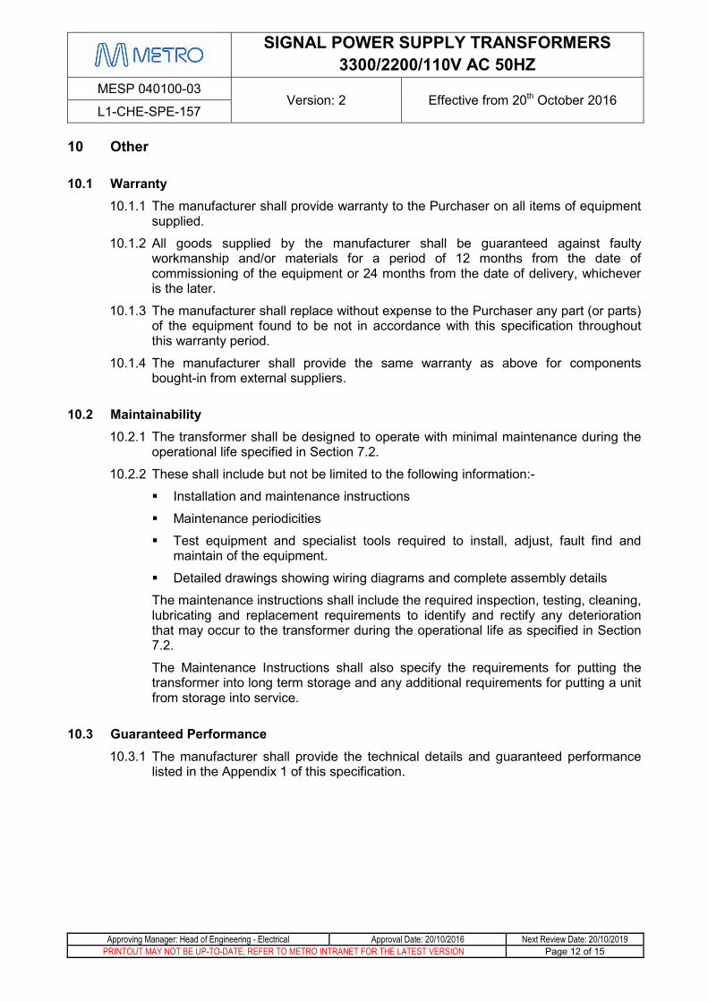
10 Other
10.1 Warranty 10.1.1 The manufacturer shall provide warranty to the Purchaser on all items of equipment
supplied.
10.1.2 All goods supplied by the manufacturer shall be guaranteed against faulty workmanship and/or materials for a period of 12 months from the date of commissioning of the equipment or 24 months from the date of delivery, whichever is the later.
10.1.3 The manufacturer shall replace without expense to the Purchaser any part (or parts) of the equipment found to be not in accordance with this specification throughout this warranty period.
10.1.4 The manufacturer shall provide the same warranty as above for components bought-in from external suppliers.
10.2 Maintainability 10.2.1 The transformer shall be designed to operate with minimal maintenance during the
operational life specified in Section 7.2.
10.2.2 These shall include but not be limited to the following information:-
Installation and maintenance instructions
Maintenance periodicities
Test equipment and specialist tools required to install, adjust, fault find and maintain of the equipment.
Detailed drawings showing wiring diagrams and complete assembly details
The maintenance instructions shall include the required inspection, testing, cleaning, lubricating and replacement requirements to identify and rectify any deterioration that may occur to the transformer during the operational life as specified in Section 7.2.
The Maintenance Instructions shall also specify the requirements for putting the transformer into long term storage and any additional requirements for putting a unit from storage into service.
10.3 Guaranteed Performance 10.3.1 The manufacturer shall provide the technical details and guaranteed performance
listed in the Appendix 1 of this specification.

SIGNAL POWER SUPPLY TRANSFORMERS 3300/2200/110V AC 50HZ
MESP 040100-03 Version: 2 Effective from 20th October 2016
L1-CHE-SPE-157
Approving Manager: Head of Engineering - Electrical Approval Date: 20/10/2016 Next Review Date: 20/10/2019 PRINTOUT MAY NOT BE UP-TO-DATE; REFER TO METRO INTRANET FOR THE LATEST VERSION Page 13 of 15
11 Packaging and Delivery 11.1.1 The transformer shall be individually and securely packed to avoid mechanical
damage.
11.1.2 All transformers shall be packaged and delivered in a manner such that their subsequent in-service performance remains unaffected.
11.1.3 The packaging shall be labelled in accordance to VRIOG Standard “General Requirements for Labelling of Signalling Equipment” VRIOGS 012.7.30, Section 5.4.
12 Appendices Appendix 1: Details and Guaranteed Performance to be Supplied by Manufacturer

SIGNAL POWER SUPPLY TRANSFORMERS 3300/2200/110V AC 50HZ
MESP 040100-03 Version: 2 Effective from 20th October 2016
L1-CHE-SPE-157
Approving Manager: Head of Engineering - Electrical Approval Date: 20/10/2016 Next Review Date: 20/10/2019 PRINTOUT MAY NOT BE UP-TO-DATE; REFER TO METRO INTRANET FOR THE LATEST VERSION Page 14 of 15
Appendix 1: Details and Guaranteed Performance to be Supplied by Manufacturer
Rated Power kVA RMS
Rated Voltage kV RMS
Rated Current A RMS
Maximum Inrush Current A RMS
Iron Losses (at rated voltage) W
Copper Losses (at rated current) W
Efficiency of normal continuous output %
Efficiency at half continuous output %
Insulation Level (fully assembled)
Lightning impulse withstand voltage: kV peak
Power frequency withstand voltage: kV RMS
Clearance in Air Phase to Earth: mm
Phase to Phase: mm
Overall Dimensions
Height: mm
Width: mm
Depth: mm
Vibration mm
Shock mm drop
Mass of core and windings kg
Mass of enclosure and fittings kg
Total Mass kg
Enclosure thickness mm
Is the transformer encapsulated YES / NO