Embed Size (px)
Citation preview

MESKO ROL Z-175 MOWER
MANUAL & SPARE
PARTS LIST

1
CONTENTS:
1. EU DECLARATION OF CONFORMABILITY ………………………………………. 2
2. INTRODUCTION ………………………………………………………………………... 3
3. APPROPRIATE USE OF THE MACHINE ……………………………………………. 3
4. SAFETY OF USE …………..…………………………………………………………….. 4
4.1. General safety principles ………………………………………………………. 4.2. Detailed safety principles ………………………………………………………
4 5
4.2.1. Preparation for work ……………………………………………………. 4.2.2. Transporting …………………………………………………………….. 4.2.3. Working ………………………………………………………………… 4.2.4. Disconnecting the mower from the tractor for the stop and storage …… 4.2.5. Technical maintenance …………………………………………………. 4.2.6. Safety signs ………………..…………………………………………….
5 6 6 7 7 8
5. MOWER OPERATING ………………………………………………………………….. 10
5.1. General characteristics and description of the mower …………………………. 5.2. Preparation for transport and transporting ……………………………………...
10 11
5.2.1. Linking mower and tractor into a working unit ………………………... 5.2.2. Assembling a PTO driver shaft ………………………………………… 5.2.3. Transporting the mower mounted on the tractor ……………………….
11 12 12
5.3. Setting the mower in working position …..…………………………………….. 5.4. Mowing .………………………………………………………………………... 5.5. Preparation for the stop and disconnecting the mower from the tractor ………..
13 14 15
6. TECHNICAL MAINTENANCE ………………………………………………….......... . 15
6.1. Routine technical maintenance ………………………………………………… 6.2. Lubrication ………………………………………………………………........... 6.3. Preservation and storage ….…………………………………………………….
16 17 17
7. TECHNICAL CHARACTERISTICS .………………………………………………….. 17
8. PARTS LIST ……………………………………………………………………………… 19

2
1. EU DECLARATION OF CONFORMABILITY FOR MACHINES: We, the company “MESKO-ROL” Sp. z o.o. 26-111 Skarżysko-Kamienna, ul. I.Mościckiego 51, Poland declare with full responsibility that machine SUSPENDED ROTARY MOWER Z 175-1
№ ………………………… which this declaration refers to, complies with requirements of: • Directive 98/37/EC – Machinery changed with a Directive No. 98/79/EC • Decree of Minister of Economy of 20.12.2005. (Dz.U. No. 259, pos. 2170 of 28.12.2005.) • harmonized standards:
- PN-EN 292-1 - Basic notions, general principles of projecting - PN-EN 292-2 - Basic notions, general principles of projecting - PN-EN 294 - Safety distances preventing from reaching dangerous areas with upper
limbs. - PN-EN 745 - Agricultural machinery. Rotary and swingle mowers. Requirements
regarding safety. - PN-EN 1553 - Agricultural machinery. Agricultural self-propelling, suspended, half-
suspended and attached machines. Common requirements regarding safety. • non-harmonized standards:
- PN-ISO 11684:1998. Tractors, agricultural and forest machines, motor tools. Safety signs and warning pictograms. General principles.
Skarżysko-Kamienna, 01.07.2008. Jacek Kowalski President of Board of “MESKO-ROL”

3
2. INTRODUCTION
Considering the importance of the information, this service manual constitutes an inseparable part of the mower. Compliance with all recommendations of this manual will let you optimally exploit the machine. Careful reading will ensure safe and effective work with the mower. The mower is made according to the safety standards’ requirements. Compliance with the warnings and instructions of this manual guarantees the safety of the user. To use the machine failure-free for many years we recommend usage of only original spare parts produced by “MESKO-ROL” Ltd. If you have any questions after reading the manual please contact the salesman or Sale&Marketing Department of “MESKO-ROL” Ltd.: tel.: 0048 41 2534121 fax. 0048 41 2533309 e-mail: [email protected] webpage: www.mesko-rol.com.pl
„MESKO-ROL“ Ltd. constantly tries to improve its products. We reserve ourselves the right to introduce any changes and improvements which we consider necessary. We have no obligation for modernizing already sold machines.
3. APPROPRIATE USE OF THE MACHINE
The mower is assigned only for agricultural works - mowing the grass and low-stem green forage on even fields and meadows. Using this machine for other purpose will be understood as an inappropriate. Fulfillment of the manufacturer’s requirements regarding usage of the mower, servicing and repairs as well as thorough compliance with these requirements is a condition of appropriate usage. The mower should be used and repaired only by a person who is acquainted with its characteristics and rules of behaving due to safety principles. Rules relating to accident prevention as well as all basic rules of the safety and occupational medicine, and also the traffic rules should be always complied with. Changes made by an unauthorized person can relieve the producer from the responsibility for possible harms and damages.

4
4. SAFETY OF USE
IMPORTANT INFORMATION FOR A USER
THE WARNING SYMBOL
This warning symbol points important information referring danger to body or life of people and animals, which is showed in the service manual. If you see the symbol – be aware and read carefully the given information.
4.1. GENERAL SAFETY PRINCIPLES
BE CAREFUL – THOROUGHLY READ THE INSTRUCTIONS IN ORDER NOT TO EXPOSE YOURSELF AND OTHERS TO A DANGER.
REMEMBER to comply with safety principles and keep the precautionary measures referring the mower as well as safety of use. Every user must completely know all the possible dangers and ways of avoiding the harm or damages.
NEVER let the children or youth under 18 operate the mower.
NEVER let the people unacquainted with maintenance and safety principles operate the mower. NEVER let the children play on the mower or nearby, even when it is not working or stored. BEFORE starting the mower make sure that there is no people or animals in a 50 m distance from the mower.

5
4.2. DETAILED SAFETY PRINCIPLES. 4.2.1. PREPARATION FOR WORK
• CAREFULLY read the service manual. Be absolutely sure that you are acquainted with all
the safety and mower operating instructions referring the preparation for work, transport and storage of the machine. If you do not follow the given instructions the producer do not answer for the possible harms or damages.
• THE USER should have carefully buttoned up, not too loose clothing to avoid catching by
protruding parts or possible driving into rotating parts. • FOR DRIVING the mower use the PTO drive shaft with one-way clutch of the type given in
the manual. Protect shields of the PTO shaft against turning according to the PTO shaft service manual. The PTO shaft must have complete shields. Do not use PTO shaft that is not working properly or has damaged shields.
• CONTROL the condition of the mower, tighten the bolts and check the fastening of all the
moving and protecting elements before linking the mower and tractor into a working unit. • WHILE CONNECTING AND DISCONNECTING the mower to and from the tractor be
especially careful. • VERY CAREFULLY approach the mower with the tractor to set the fastening points of the
three-point suspension system and power take-off – power input shafts in a close position. No person should be between the tractor and the mower at that time. All the operations of connecting the tractor with the mower should be executed only after you stop the engine, immobilize the tractor with a handbrake and take the ignition key off.
• ALWAYS make sure there is no people or animals near the mower, before lifting. • DO NOT LEAVE the mower in lifted position on the tractor’s three-point suspension
system. • BEFORE YOU LEAVE the tractor ALWAYS lower the mower onto the still and flat
ground, stop the drive of PTO shaft, stop the engine, take the ignition key off. • NEVER USE the mower without protective shields and aprons. Working without shields or
with damaged shields is forbidden because of the danger of throwing stones or other hard objects by rotating drums.
• START the mower after setting all elements in working position. Starting the mower in
transport position is FORBIDDEN. • BEFORE setting the mower in transport position, ALWAYS disconnect the PTO shaft from
the tractor. • NEVER start the mower in closed rooms due to harmful exhaust gases.

6
• ALWAYS use front weights, when the front axle of the tractor is too lightened. • YOU CAN APPROACH the mower only when the tractor’s engine and the mower’s drums
are totally still. • NEVER operate the mower while being under alcohol, drugs or medicines that can restrain
the ability of concentration. 4.2.2. TRANSPORTING
• REMEMBER that the mower can be transported on the tractor only when set in the transporting position.
• During the transport on public roads the mower should be equipped with cautionary lighting
panels according to obligatory home traffic regulations.
4.2.3. WORKING
• BEFORE YOU SETTLE the mower for work, every time stop the engine, take the ignition key off and immobilize the tractor with a handbrake.
• BE ESPECIALLY CAREFUL when recharging the mower from transport to working
position.
• CONNECT THE PTO DRIVE SHAFT to the tractor and machine after setting the mower in working position. Pay close attention to proper fastening the shaft on the splines of tractor’s drive.
• BEFORE YOU START the machine make sure there is no people or animals in a 50 m
distance. The support should be lifted.
• NEVER START the mower when it is lifted.
• WHEN WORKING pay attention to any alarming vibrations or changes in sounds of working.

7
4.2.4. DISCONNECTING THE MOWER FROM THE TRACTOR FOR THE STOP AND STORAGE.
• DISCONNECT THE PTO SHAFT only after you put the mower on the ground, stop the engine, immobilize the tractor and take the ignition key off.
• BEFORE YOU DISCONNECT the mower from the tractor lower the support and block
it with a pin. • PLACE the mower for the stop and storage in the room, where other people, children or
animals do not enter. • PROTECT the mower against the reach of children.
• DURING STORAGE ALWAYS put the mower on the support.
4.2.5. TECHNICAL MAINTENANCE
• MAINTAIN the mower during the stop, before connecting it to the tractor. If you have to service it when connected to the tractor, proceed as follows:
- put the mower on the ground - stop the engine, immobilize the tractor with a handbrake, take the ignition key off and
disconnect the PTO shaft After switching off the drive, drums of the mower rotate with inertial reaction for about one minute and you must wait until they stop.
• EVERYDAY CHECK the condition of the bolt connections and tighten the loosed parts
if necessary, before you start the work. • CONTROL THE LEVEL of possible wear or damage of parts, especially knives and knife
holders, and replace them if necessary early enough with original spare parts offered by the producer of the mower.

8
4.2.6. SAFETY SIGNS
The warning and information labels are put on the mower in places showed at Fig.1. Warnings and information are given as pictograms that show clear instructions where to put especial attention to work safely with the mower. Carefully watch every label and thoroughly check the meaning in this chapter of the service manual. Keep the labels clear and readable while using the mower. If any label is damaged, illegible or lost replace it with a new one. New assembles and parts which are replaced during repairs should be marked with all necessary labels shown in this manual. You can purchase new labels at producer or dealer. While ordering, please advise catalogue number of the label ( given at Fig.1.) List of the warning and information labels placed on the mower.
GENERAL WARNINGS. During operating the mower comply with all warnings and safety principles marked with this sign. CAREFULLY READ the service manual before you start to work with the machine.
STOP THE TRACTOR’S ENGINE and take the ignition key off before any service or repair. DO NOT TOUCH moving parts of the machine until they are absolutely still.
MIND THE SPINNING KNIFE. Stay away from the spinning knives while mower is working.
DO NOT USE THE MOWER: 1. closer than 50 m from people or animals 2. on a stony ground or ground with constant obstacles.
DO NOT STAY within the bend of the unit while tractor’s engine is working.
DO NOT STAY OR MAINTAIN THE MOWER WITHIN THE LIFTED MACHINE.

9
91,5 mm
Label TR 338/A
Label TRA 5
Label KR 852
Label KR 853Label KP 00.00.12
Label TR 1011
Label TR 46 B

10
Fig.1. Placing the warning and information labels on the mower.
5. MOWER OPERATING.
You can use and operate the mower after reading carefully the service manual.
5.1. GENERAL CHARACTERISTICS AND DESCRIPTION OF THE MOWER.
The Z 175-1 rotary mower cooperates with an over 23 kW tractor of II category. It is assigned for mowing grass and low-stem green forage on even and sloped up to 12° fields and meadows. In case of problems with the power take-off shaft please contact with a producer of this particular PTO shaft. The knife CMA 120 is not under warranty. WARNING! For proper work use appropriate type of PTO drive shaft: Torque – 400 Nm, Lmin. – 560 mm, Lmax – 885 mm. Producer recommends PTO shafts of SIPMA, Poland – type C 51120 (5R-502-2-BA-J501) www.lfmr.pl The Z 175-1 rotary mower consists of the following main assemblies (Fig.2.):
- three-point frame (1) - indirect drive (2) - main drive (3) - complete housing (4)
Fig. 2. Z 175-1 suspended rotary mower.
1- three-point frame, 2 – indirect drive, 3 – main drive, 4 – complete housing, 5 – drum, 6 – lock, 7 – PTO shaft housing, 8 – spring, 9 – tightening pin.

11
The mower is supplied partly disassembled. Assemble the machine in accordance with Fig. 12., 13. and 16. of the parts list. The three-point frame 1. is attended for mounting the mower on tractor. The power is transmitted to the power take-off shaft through the jointed shaft, belt transmission (indirect drive 2.) to the main drive 3. equipped with two drums 5. Three CMA120 cutting knives are rotationally mounted in each drum and they deviate when they hit an obstacle, e.g. a stone, which protects them from getting damaged. The knives have two cutting edges. When one edge wears out, the cutting tools can be installed in the other drum, which rotates in the opposite direction, thus they preserve dual life. Each drum has replaceable transport strips preventing grass from getting wrapped in the drum and decreasing the friction and wearing of drums. The drums and cutting knives whirl in opposite direction forming the mowed green fodder into a swath roller. The tightening pin 9. and indicator enables the tightening of the V-belt assembly. The mower is equipped with a lock 6. which, in case of hitting an obstacle, reacts causing the machine to move backwards. If that happens you must stop immediately and withdraw a little, so that the lock is automatically locked up again. In order to assure operational safety the mower is outfitted with housing 4. and aprons fastened to them. The end of power take-off shaft is protected with a special housing 7. Spring 8. connecting the lift with the three-point frame decreases the pressure of drums to the base preventing the turf from being devastated and decreasing wearing-out of the drum plates. When working on uneven ground (max. decrease of pressure to the base) and with lighter tractors on steep slopes a spring should be fixed in the down hole (best steerability of the tractor is then achieved).
5.2. PREPARATION FOR TRANSPORT AND TRANSPORTING
CAUTION !
When charging to the working or transport position do not get between the tractor and the cutting unit, setting the mower in working or transport position should be done closely to the ground! When charging the mower to transport position, first, with utmost severity, disconnect the jointed shaft from the tractor. Before disconnecting the mower from the tractor, place the mower on a support 4. and rest the jointed shaft on the yoke 5. (Fig. 3.)
5.2.1. LINKING THE MOWER AND THE TRACTOR INTO A WORKING UNIT
• Set up the three-point frame in a transport position – the transport rod 1. should be placed on
mandrel 2. of the three-point frame and secured with a pin 3. (Fig. 3.). • Connect the three-point frame 1. of the mower with the three-point suspension system of the
tractor in accordance with the manual of the tractor. • Lift the support 4., set it on the high position and block with a pin.

12
Fig. 3. Linking of the mower and the tractor into a working unit.
1 – transport rod, 2 – mandrel, 3 – pin, 4 – support, 5 – yoke. 5.2.2. ASSEMBLING A PTO DRIVE SHAFT
For driving the mower use the PTO drive shaft of the type given in the manual. CAUTION! Always use shields of the PTO shaft and tractor’s drive shaft. Shields of PTO shaft must be protected against turning according to the PTO shaft service manual.
5.2.3. TRANSPORTING THE MOWER MOUTED ON A TRACTOR.
CAUTION ! During the transport on public roads the mower should be equipped with cautionary lighting panels according to obligatory home traffic regulations.
For driving to the workplace, disconnect the jointed shaft of the mower from the PTO shaft of the tractor and rest it on the yoke 1. During transport the mower should be raised on a hydraulic lift with the cutting tool turned backwards for safety.
Fig. 4. Mower in transport position.

13
1 – yoke. 5.3. SETTING THE MOWER IN WORK POSITION
CAUTION ! Before releasing the transport rod from the mandrel, position the mower and tractor horizontally; if necessary, secure the mower against unintended departing.
• Lower the mower to the ground, release the transport rod 1., mount the PTO shaft on the yoke 9. and lock the transport rod in the upper position.
• Set up mower in the work position, fasten lock 4. on mandrel 2. and secure with pin 3. • Connect the PTO drive shaft with the tractor. • Set up the length of the upper pull rod in such a way that the drums in the work position are
parallel to the base or slightly slopped forward. In order to avoid fodder lost due to dual cutting, never slope the machine backwards. Set up the bottom balance lever of the tractor in such a way that the mower is positioned as shown in Fig. 6.
NOTICE: Depending on the length of the upper pull rod of the tractor, the front as well as rear holes of the three-point frame can be made use of.
Fig. 5. Mower in work position.
1 – transport rod, 2 – mandrel, 3 – pin, 4 – lock, 5 – securing nut, 6 – nut,

14
7 – doubling nut, 8 – spring, 9 – yoke.
Fig. 6. Correct setting of the mower.
CAUTIONS !
• Start the mower only when set in working position. • Before working with the machine read the service manual carefully. • It is inadmissible to lift the mower on a hydraulic lift with power feed on and rotating
drums. • Never use the mower without shields and aprons. Operating the mower without shields
or with damaged shields is inadmissible due to danger of thrown out hard objects. • Before switching on the PTO shaft secure the jointed shaft shields against turning. • It is inadmissible to use the mower at a distance smaller than 50 m from strangers and
on stony ground or ground with constant obstacles. Handle with care especially near roads and roadways.
• In no instance should the speed of PTO shaft be increased above 540 rpm. • In case of excessive unloading of the front axle of the tractor, use front wheel weights in
order to load additionally . • When running on steep slopes the mower should be on the higher side of the slope. • Running the mower at high speeds of drums requires taking watchful attention to all
kind of unbalance causing vibration which can result in serious damage of the mower. If increased vibration or a changed noise of operating mower is noticed, stop working immediately. Continue the work with the machine only after you find and remove the cause.
• Conduct operations on the mower only after placing the mower on the ground, turning off the PTO shaft, stopping the engine and immobilizing the tractor with a handbrake or placing the wedges under the tractor’s wheels.
• Do not start the engine or try to operate the mower indoors due to harmful exhaust gases.
5.4. MOWING.
• Slowly switch on the mower drive until achieving a full number of revolutions before the mowing starts, that is 540 rpm
• Match driving speed to the ground conditions and type of mowed material; avoid uneven and stony ground.

15
• When mowing on uneven ground or in cooperation with lighter tractors on steep slopes suspend the spring (pos. 8. Fig.5.) to down hole.
5.5. PREPARATION FOR THE STOP AND DISCONNECTING THE MOWER FROM THE TRACTOR.
To disconnect the mower from the tractor proceed as follows:
− Set the mower in the transport position. − Set up the support 4 (Fig. 3.) in position for the stop. − Disconnect the PTO shaft from the tractor and put it on the yoke 5. − Disconnect the tractor’s three-point suspension system from the mower.
6. TECHNICAL MAINTENANCE CAUTION ! • Regularly control the condition of the knife-holder pins. When the pin wears out
halfway absolutely replace the knife-holders (Fig.7.). • When replacing the knives, notice should be taken to the correct mounting; they should
rotate freely on the pins. • Always fasten the knife-holders with original bolts M12x25-8.8 and nuts P M12-8-A,
tighten them with a torque 85 Nm.
Fig. 7. Minimal thickness of the knife-holder pin.
• The condition of drums should be regularly checked. If the drum plates show cavities caused by cutting tools or if they are overworn, proceed as follows:
- unscrew three bolts 7. which are screwed in at the bottom of sliding plate (Fig. 15.)
- disassemble the sliding plate - fasten the knife-holders 1. (Fig. 9.) in another place to let the cutting tool
adhere to an unworn surface. • Immediately replace damaged or worn drums.

16
6.1. ROUTINE TECHNICAL MAINTENANCE
• Regularly check the condition of knives. Each drum should be equipped with three new or uniformly worn CMA 120 knives. A suitable wrench is provided for replacing the knives (Fig. 8.). Correctly settled knife should easily spin on the knife-holder pin. Fig. 8. shows how to replace the cutting knives.
• Systematically check the condition of transport strips. If they are worn to such a degree that
the drum can untimely wear out, replace strips with new ones. • During the season check the functioning of the lock every day (pos. 4. Fig. 5.). If the
mechanism functions while mowing, even though no obstacle has been struck, this means that the force of the spring is too small and it should be tighten better with a securing nut (pos. 5. Fig. 5.).
• During the first few hours of work carefully watch the behaviour of V-belts, after 0,5 –
4 hours of work under full load – tighten belts. The ‘x’ clearance (Fig. 5) should be approximately 1 mm. This clearance is adjusted with nuts 6. and 7. Proceeding like this the initial stretch is considered. After next 24 hours of work check the indicator again and tighten belts if necessary. Maximum ‘x‘ clearance cannot exceed 3 mm. Next inspections can be done even after few hundred hours of work. Notice: If the V-belts are stressed more than the indicator is showing, a damage to ball bearings can be caused in result of overloading.
• After a few working hours of a new or repaired machine check if all the bolts and nuts are
properly tightened, especially the bolts tightening the lift. Repeat the checking in regular intervals.
• If the gasket between the shield and main frame (for example after repairing the machine)
needs to be replaced, use only original gaskets. Stick them on exactly in place of the old one. Bolts that connect shield with main frame should be tighten with torque 48 Nm.
Fig. 8. Method of replacing the knives.

17
Fig. 9. Position of knife-holders.
1 – knife-holder.
6.2. LUBRICATION.
• During the operational use the mower should be lubricated every day (the lubricating points are shown in Fig.10.)
• The main frame filled with grease “Liten EPX 00” ORLEN OIL doesn’t require checking. If a repair has been conducted, the amount of lubricant should be refilled! The lubricant should level up to the bottom part of the horizontal shaft (5,5 kg).
Fig. 10. Lubricating points.
6.3. MAINTENANCE AND STORAGE
- Every time after finished work clean the machine of plant remains and dirt and check the connection of parts and assemblies.
- When the season is over, clean the mower and carry out a technical survey. If any defects are found, remove them. If paint has come off in some places, they should be cleaned of rust and repainted. Cover unpainted parts with a thin layer of grease e.g. STP, vaseline. It is recommended to store the mower indoors to secure it from moisture and precipitation.
7. TECHNICAL DATA
- working width……………………………………… 1650 mm - transporting width…………………………….……. 1450 mm - transporting length……………………………….… 2900 mm - height………………………………………………. 1150 mm - cutting height………………………………………. 40 mm - number of drums…………………………………… 2 - number of knives …….…………………………….. 6 - PTO shaft ………………………………………….. 540 rpm - weight………………………………………………. 380 kg - power required …………………………………….. 24 kW - tractor ……………………………………………… II Cat.

18
NOTES

19
PARTS LIST
When ordering parts, please advise the name and number of the part and the year of production of the mower.
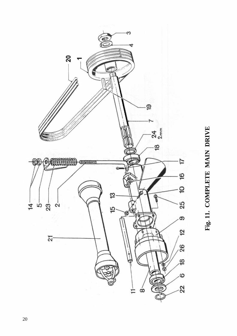
20
Fig
. 11.
CO
MP
LET
E M
AIN
DR
IVE

21
Notes
Bondioli & Pavesi
SIPMA
Number of pcs
1 1 1 1 1 1 1 1 1 1 1 4 1 2 1 1 1 2 1 1 1 1 1 1 4 4
Plant part number
KR 680 MTA 145V MT 174V MT 301V MT 362 MT 365V MTA 366 MTA 367 NP 0381 MTA 0375 MT 376V NP 0291 ND 1106V ND 2006V ND 2092V ND 3109V ND 4006V ND 5027 ND 7003/A NP 0454 C-51120 PZ 72V PZ 327 TH 79(20) ND 1063V ND 2091V
Name of part or assembly
Complete pulley Tightening pin Nut M30x1,5 H=12 Lock-washer Indicator Plate Driving shaft Distance sleeve Housing Bearing casing Mandrel Round washer 8,5-Fe/ZN9cC Bolt M6x55-8.8-B-Fe/Zn8cC Nut M16-8-B-Fe/Zn8cC Nut P M6-8-A-Fe/ZN8cC Washer ZM K15-Fe/Zn9cC Cotter pin S-Zn 4x32 Ball bearing 6207-2RS Parallel key AB 8x7x45 Set of V-belts SPB 2800 Jointed PTO drive shaft with one-way clutch Spring ring Spring Washer 2,0x35,2x43 Bolt M8x16-8.8-B-Fe/Zn8cC Nut P M8-8-A-Fe/Zn8cC
Ord. №
1 2 3 4 5 6 7 8 9 10 11 12 13 14 15 16 17 18 19 20 21 22 23 24 25 26 34

22
Fig. 12. COMPLETE INTERMEDIATE FRAME

23
Notes
Number of pcs
3 1 1 1 1 2 1 1 1 1 1 1 1 1 1 1 1 1 4 1 1 3 1 4 1 1 1 2 1 1 4 1 1 4 4
Plant part number
BP 431V GT 03 GT 92V KR 075 KR 76 LD 40 KR 77 KR 79 MT 97V MT 00122 MT 0123 ST 13 MT 166V MT 0168 MTA 0175 MT 0485 MT 0486 MT 487V ND 1009V ND 1123V ND 1303V ND 1438V ND 1439V ND 2084V ND 2085V ND 2091V ND 3001V ND 4006V ND 4066V ND 9004V NP 0297V PZ 50V PZ 327 ND 9813V NP 0236V
Name of part or assembly
Washer Intermediate frame Sleeve Complete shield Shield Hinge Holder Holder Mandrel 16h11x65x58 Complete lock Lock Flat bar Mandrel Transport rod Support Complete support Complete support. Distance sleeve Bolt M10x30-8.8-B-Fe/Zn8cC Bolt M8x70-8.8-B-Fe/Zn8cC Bolt M12x200-8.8-B-Fe/Zn8cC Bolt M16x35-8.8-B-Fe/Zn8cC Bolt M16x60-10.9-B-Fe/Zn8cC Nut P M10-8-A-Fe/Zn8cC Nut P M12-8-A-Fe/Zn8cC Nut P M8-8-A-Fe/Zn8cC Washer K 17-Fe/Zn9cC Cotter pin S-Zn 4x32 Cotter pin S-Zn 8x50 Grease nipple M6 Round washer 10,5-Fe/Zn8cC Stopper Spring Grease nipple M8x1x180 Bolt M10x20-8.8-B-Fe/Zn8cC
Ord. №
1 2 3 4 5 6 7 8 9 10 11 12 13 14 15 16 17 18 19 20 21 22 23 24 25 26 27 28 29 30 31 32 33 34 35

24
Fig. 13. THREE-POINT FRAME ASSEMBLY

25
Notes
Number of pcs
1 1 1 1 1 1 1 1 1 1 1 1 1 1 1 1 1 1 1 1 1 2 1 1 4 1 1 1 1 1 1 1 2
Plant part number
MT 90V GT 30 KR 0450 GT 45 KR 0220 GT 0212 KR 0420 GT 0245V HK 0028V KR 0210 MT 84V MT 85V MT 089 ND 1244V MT 100V MT 0118 MT 138V MT 141V ND 1184V ND 1003V KR 00450 ND 2084V ND 2090V ND 3001V ND 4006V ND 4009V MT 97V ND 8002V ND 9004V ND 9031V PZ 25V PZ 51 GT 317
Name of part or assembly
Pin Flat bar Complete flat bar Distance sleeve Three-point frame Hinged assembly Complete rod Complete pin Complete mandrel Cap Washer Distance sleeve Swinging clamp Bolt M16x90-8.8-B-Fe/Zn8cC Pin Complete lever Sleeve Washer 3x60,5x76 Bolt M10x90-8.8-B-Fe/Zn8cC Bolt M10x80-8.8-B-Fe/Zn8cC Lever assembly Nut P M10-8-A-Fe/Zn8cC Nut P M16-8-A-Fe/Zn8cC Washer K 17-Fe/Zn9cC Cotter pin S-Zn 4x32 Cotter pin S-Zn 5x60 Mandrel 16h11x65x58 Mounting ring Z60 Grease nipple M6 Pin A 11x45-Fe/Zn12cC Plug Spring Plate
Ord. №
1 2 3 4 5 6 7 8 9 10 11 12 13 14 15 16 17 18 19 20 21 22 23 24 25 26 27 28 29 30 31 32 33

26
Fig. 14. COMPLETE MAIN FRAME

27
Notes
Number of pcs
1 1 1 1 1 1 1 1 1 1 1 1 1 1 1 - 1 - 1 1 1 1 1 - 3 4 15 15 1 1 1 2 1 1 1 4 1 1 1 4 1 4 4 4
Plant part number
CH 17 KR 16 CH 180V CM46 KR 20 GT 98 GT 99 KR 670 KR 0020 TC 94 KR 33 KR 0100 MT 5 MT 28 MT 45 MT 0062 MT 63(10) MT 0063 MT 165 MT 170 MT 174V MT 301V MT 310(10) MT 00310 MT 337 ND 9305/A NP. 0236V ND 2084V ND 9905 NP 0155 ND 4007V ND 5004 ND 5008 ND 5029 ND 6015 ND 7002 ND 7004 PZ 58V PZ 48V ND 6304 GT 246 ND 1064V ND 2091V ND 3030V
Name of part or assembly
Distance sleeve Washer Nut M30x1,5 Plug Cover Shaft Distance sleeve Pulley Complete cover Bevel gear Rating plate Main frame Nut Plug Driving shaft Set of distance washers Washer 1,0x50x61,8 Set of distance washers Ring Distance sleeve Nut M30x1,5 H=12 Lock-washer Washer 1,0x30,2x38 Set of distance washers Bevel gear Rivet 2x8 Al. B Bolt M10x20-8.8-B-Fe/Zn8cC Nut P M10-8-A-Fe/Zn8cC Sealing tape 20x4 Steel wire 1,2 gca-II-Na Cotter pin S-Zn 5x32 Ball bearing 6206 Ball bearing 6305 Two-row ball bearing 4206 Packing-ring A 45x62x7 Key A 8x7x35 Key A 8x7x55 Spring ring Spring ring Packing-ring A 68x4 Shield Bolt M8x20-8.8-A-Fe/Zn8cC Nut P M8-8-A-Fe/Zn8cC Washer 2x8,4x25-Fe/Zn8cC
Ord. №
1 2 3 4 5 6 7 8 9 10 11 12 13 14 15 16 17 18 19 20 21 22 23 24 25 26 27 28 29 30 31 32 33 34 35 36 37 38 39 40 41 42 43 44

28
Fig. 15. DRUMS ASSEMBLY

29
Notes
Number of pcs
1 2 2
6+6 2 2 6 2 2 2 - - 4 4 6 2 12 8 8 8 2 2 4 2 2 6 2 2 4 6 12 12 12 2 2 2 2 2 2 2 2
Plant part number
CM 059 KR 0700 KR 060 CMA 120 KR 063 GT 64 GT 71V KR 500 GT 84 GT 331 MT 0062 MT 0063 MT 0071 MT 71V KR 660 GT 83 ND 1072V ND 1013V ND 2003V ND 3101V ND 5034 ND 5093 ND 5035 ND 5009 ND 6002 ND 6025 ND 7001 ND 7004 ND 8003 KR 065 ND 3105V NP 0302V ND 2085V MT 179R GT 103 ND 8011 TH 78(20) MT 34V MT 62(15) AH 00132 ND 8089
Name of part or assembly
Cutting knife spanner Sliding plate Complete drum Cutting knife Drum hub Bevel gear Lock screw Vertical roller Distance sleeve Hub Set of distance washers Set of distance washers Complete transport strip Transport strip Washer Ring Bolt M12x25-8.8-B-Fe/Zn8cC Bolt M6x16-8.8-B-Fe/Zn8cC Nut M6-8-B-Fe/Zn8cC Washer 6-Fe/Zn9Cc Ball bearing 51109 CX22 Ball bearing 6208-2RS CX22 Ball bearing 6210-2RS C3 Ball bearing 6305-2RS Packing-ring A 40x62x10 Parking-ring 50,08x2,62 Parallel key A 8x7x30 Parallel key A 8x7x55 Spring mounting ring W 62 Complete knife holder Washer 12-Fe/Zn9cC Bolt P M12x25-8.8-Fe/Zn8cC Nut P M12-8-A-Fe/Zn8cC Nut M25x1,5 Distance ring Spring mounting ring Z 50x2 Distance washer Toothed washer Washer 1,5x25,2x33 Washer Spring mounting ring Z 40x2,5
Ord. №
1 2 3 4 5 6 7 8 9 10 11 12 13 14 15 16 17 18 19 20 21 22 23 24 25 26 27 28 29 30 31 32 33 34 35 36 37 38 39 40 41

30
Fig. 16. COMPLETE HOUSING

31
Notes
Number of pcs
1 1 2 - 1 1 1 2 1 1 1 5 8 8 1 1 7 7 21 8 4 35 40 14 1 3 1 3 6 6
Plant part number
KR 9 KR 90 KR 92 KR 009 KR 91 KR 930 KR 0094 KR 95 KR 0960-1 KR 0970-1 KR 099 NP 0297V NP 0308V NP 0307V NP 0306V ND 1009V NP 0305V ND 1019V ND 1171V ND 1099V NP 0304V ND 2092V NP 0309V ND 2084V KR 094 PZ 101V KR 940 NP 0318 ND 1064V ND 2091V
Name of part or assembly
Front shield Back shield Bracket Complete shield Side shield Apron Complete side apron Corner Complete back bow Complete front bow Complete bracket Round washer 10,5-Fe/Zn9cC Nut M6-8-Fe/Zn8cC Bolt N-F M6x12-8.8-Fe/Zn8cC Bolt M10x50-8.8-B-Fe/Zn8cC Bolt M10x30-8.8-B-Fe/Zn8cC Bolt M6x16-8.8-B-Fe/Zn8cC Bolt M6x30-8.8-B-Fe/Zn8cC Bolt M6x12-8.8-B-Fe/Zn8cC Bolt M10x40-8.8-B-Fe/Zn8cC Bolt P M10x30-8.8-Fe/Zn8cC Nut P M6-8-A-Fe/Zn8cC Round washer 6,5-Fe/Zn9cC Nut P M10-8-A-Fe/Zn8cC Bracket Bow Side apron Holder Bolt M8x20-8.8-B-Fe/Zn8cC Nut M8-8-B-Fe/Zn8cC
Ord. №
1 2 3 4 5 6 7 8 9 10 11 12 13 14 15 16 17 18 19 20 21 22 23 24 25 26 27 28 29 30

32
NOTES
![Medical education and building an on-line reputation in the world wide web 2.0 [4 Cr3 1530 Mesko]](https://img.pdfslide.us/doc/110x75/55493580b4c905054d8b4692/medical-education-and-building-an-on-line-reputation-in-the-world-wide-web-20-4-cr3-1530-mesko.jpg)


![Medical Bloggers Panel [4 Aud 1215 Mesko]](https://img.pdfslide.us/doc/110x75/558ecdb91a28abdb7e8b45e5/medical-bloggers-panel-4-aud-1215-mesko.jpg)