Embed Size (px)
Citation preview
This document is subject to change without noticeDocument No: 0011-00-07-01-000 (Issue H)Date Published: October 11, 2016 Page 1 Contributor Member
MeshConnect™ EM35x Mini Modules
DESCRIPTIONThe MeshConnect™ EM35x Mini Modules from California Eastern Laboratories (CEL) combine high performance RF solutions with the market's premier ZigBee® and Thread stacks. Available in low and high output power options (+8dBm and +20dBm), these modules can accommodate variable range and performance requirements. The tiny module footprint makes them suitable for a wide range of ZigBee and Thread applications. The MeshConnect EM35x Mini Modules are certified and qualified, enabling customers to accelerate time to market by greatly reducing the design and certification phases of development.
CEL’s MeshConnect EM35x Mini Modules (ZICM35xSP0 and ZICM35xSP2) are based on the Ember EM35x (EM357 and EM358x) System on Chip (SoC) radio ICs. Each IC is a complete single-chip solution, compliant with ZigBee, Thread, and IEEE 802.15.4. specifications.
CEL’s EM358x-based Mini Modules (ZICM358xSP0 and ZICM358xSP2) are ideal for customers requiring Over-the-Air (OTA) programming without an external Flash memory (such as Smart Energy or Home Automation), a larger memory footprint for complex application control, or the additional resources to run an IPv6-based networking stack like Thread. They also feature an optional on-board Universal Serial Bus (USB) 2.0 full-speed peripheral.
Integrated Transceiver Modules for ZigBee®/ Thread / IEEE 802.15.4Development Kit Available: ZICM-EM35X-DEV-KIT-3
EM35x Mini Modules
ZICM35xSP0 and ZICM35xSP2EmberTM EM35x Transceiver-Based Modules
• Data Rate: 250kbps • Advanced Power Management • 16 RF Channels • Industry's Premier Wireless
Networking Stacks: EmbeZNet PRO™ (ZigBee) and Silicon Labs Thread • Mini Footprint:
- 0.940" x 0.655" (23.9mm x 16.6mm)
ADDITIONAL FEATURES • Antenna Options:
1) Integrated PCB Trace Antenna 2) RF Port for External Antenna • Supports Mesh Networks • AES Encryption • FCC, CE and IC Certifications • RoHS Compliant
APPLICATIONS • Smart Energy/Grid Markets
- Thermostats - In-Home Displays - Smart Plugs • Home Automation and Control
- Energy Management - Security Devices - HVAC Control • Building Automation and Control
• Commercial and Residential Lighting - Fixtures and Control • Solar Inverters and Control • General ZigBee and Thread
Wireless Sensor Networking
ZICM35xSP0 ZICM35xSP2+8dBm +20dBm-100dBm -103dBm+108dB +123dB
Tx:Rx:
Link Budget:
KEY FEATURES:• 32-bit ARM® Cortex™-M3
• Up to 23 GPIO Pins
• SPI (Master/Slave), TWI and UART
• Timers and Serial Wire/JTAG Interface
• 5-Channel 14-bit ADC
EM357• 12kB SRAM• 192kB Flash
EM358x• Up to 64kB SRAM• Up to 512kB Flash (Supports OTA)• Optional USB Controller
Powered by Ember® ZigBee® & Thread Solutions
or

EM35x Mini Modules
Page 2This document is subject to change without noticeDocument No: 0011-00-07-01-000 (Issue H)
Contributor Member
Introduction and OverviewDescription.............................................................................................................................................................................................. 1Features................................................................................................................................................................................................... 1Applications............................................................................................................................................................................................ 1Ordering Information.............................................................................................................................................................................. 3ZICM35xSPx Product Comparison Table.............................................................................................................................................. 4Module Block Diagram........................................................................................................................................................................... 4Development Tools.................................................................................................................................................................................. 5
System Level FunctionTransceiver IC.......................................................................................................................................................................................... 6Antenna.................................................................................................................................................................................................... 6Power Amplifier....................................................................................................................................................................................... 6USB........................................................................................................................................................................................................... 7Software/Firmware................................................................................................................................................................................. 7
Electrical SpecificationAbsolute Maximum Ratings................................................................................................................................................................... 8Recommended Operating Condition..................................................................................................................................................... 8DC Characteristics.................................................................................................................................................................................. 8RF Characteristics.................................................................................................................................................................................. 9
Pin Signal and Interfaces
Pin Signals I /O Configuration............................................................................................................................................................... 10I /O Pin Assignment................................................................................................................................................................................ 10
Module Dimensions................................................................................................................................................................................ 11
Module Land Footprint........................................................................................................................................................................... 12
Processing.......................................................................................................................................................................................... 13
Agency Certifications.................................................................................................................................................................... 15
Software Compliance.................................................................................................................................................................... 16
Shipment, Storage and Handling............................................................................................................................................. 18
Quality................................................................................................................................................................................................... 18
References.......................................................................................................................................................................................... 19
Revision History............................................................................................................................................................................... 19
TABLE OF CONTENTS
EM35x Mini Modules
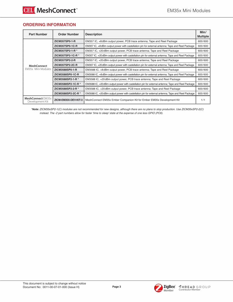
Page 3This document is subject to change without noticeDocument No: 0011-00-07-01-000 (Issue H)
Contributor Member
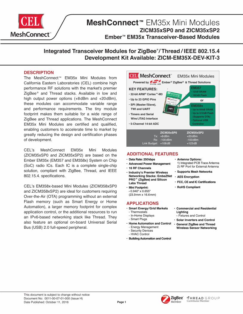
ORDERING INFORMATION
Part Number Order Number Description Min/ Multiple
MeshConnect EM35x Mini Modules
ZICM357SP0-1-R EM357 IC, +8dBm output power, PCB trace antenna; Tape and Reel Package 600/600ZICM357SP0-1C-R EM357 IC, +8dBm output power with castellation pin for external antenna; Tape and Reel Package 600/600ZICM357SP2-1-R * EM357 IC, +20dBm output power, PCB trace antenna; Tape and Reel Package 600/600ZICM357SP2-1C-R * EM357 IC, +20dBm output power with castellation pin for external antenna; Tape and Reel Package 600/600ZICM357SP2-2-R EM357 IC, +20dBm output power, PCB trace antenna; Tape and Reel Package 600/600ZICM357SP2-2C-R EM357 IC, +20dBm output power with castellation pin for external antenna; Tape and Reel Package 600/600ZICM3588SP0-1-R EM3588 IC, +8dBm output power, PCB trace antenna; Tape and Reel Package 600/600ZICM3588SP0-1C-R EM3588 IC, +8dBm output power with castellation pin for external antenna; Tape and Reel Package 600/600ZICM3588SP2-1-R * EM3588 IC, +20dBm output power, PCB trace antenna; Tape and Reel Package 600/600ZICM3588SP2-1C-R * EM3588 IC, +20dBm output power with castellation pin for external antenna; Tape and Reel Package 600/600ZICM3588SP2-2-R * EM3588 IC, +20dBm output power, PCB trace antenna; Tape and Reel Package 600/600ZICM3588SP2-2C-R * EM3588 IC, +20dBm output power with castellation pin for external antenna; Tape and Reel Package 600/600
MeshConnect EM35x Development Kit ZICM-EM35X-DEV-KIT-3 MeshConnect EM35x Ember Companion Kit for Ember EM35x Development Kit 1/1
*Note: ZICM35xSP2-1(C) modules are not recommended for new designs, although there are no plans to stop production. Use ZICM35xSP2-2(C) instead. The -2 part numbers allow for faster 'time to sleep' state at the expense of one less GPIO (PC6).
EM35x Mini Modules
Page 4This document is subject to change without noticeDocument No: 0011-00-07-01-000 (Issue H)
Contributor Member
RadioMicroLPFBalun
Cas
tella
tion
Edge
Con
nect
or Ember EM35x
24MHzXTAL
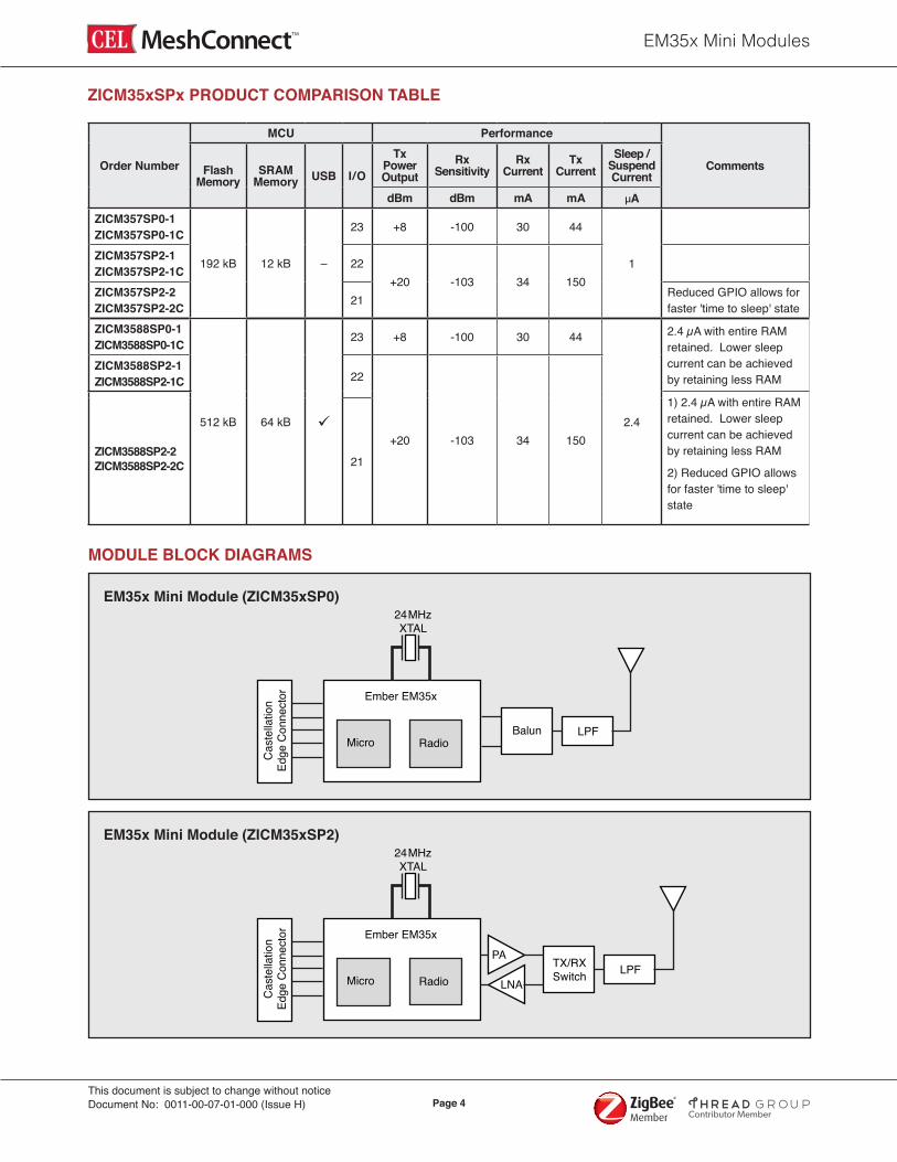
EM35x Mini Module (ZICM35xSP0)
RadioMicro
PA
LNALPFTX/RX
Switch
Cas
tella
tion
Edge
Con
nect
or Ember EM35x
24MHzXTAL
EM35x Mini Module (ZICM35xSP2)
MODULE BLOCK DIAGRAMS
ZICM35xSPx PRODUCT COMPARISON TABLE
Order Number
MCU Performance
CommentsFlash Memory
SRAM Memory USB I/O
Tx Power Output
Rx Sensitivity
Rx Current
Tx Current
Sleep / Suspend Current
dBm dBm mA mA µAZICM357SP0-1ZICM357SP0-1C
192 kB 12 kB –
23 +8 -100 30 44
1ZICM357SP2-1ZICM357SP2-1C 22
+20 -103 34 150ZICM357SP2-2ZICM357SP2-2C 21 Reduced GPIO allows for
faster 'time to sleep' stateZICM3588SP0-1ZICM3588SP0-1C
512 kB 64 kB ü
23 +8 -100 30 44
2.4
2.4 µA with entire RAM retained. Lower sleep current can be achieved by retaining less RAM
ZICM3588SP2-1ZICM3588SP2-1C 22
+20 -103 34 150ZICM3588SP2-2 ZICM3588SP2-2C
1) 2.4 µA with entire RAM retained. Lower sleep current can be achieved by retaining less RAM
2) Reduced GPIO allows for faster 'time to sleep' state
21
EM35x Mini Modules
Page 5This document is subject to change without noticeDocument No: 0011-00-07-01-000 (Issue H)
Contributor Member
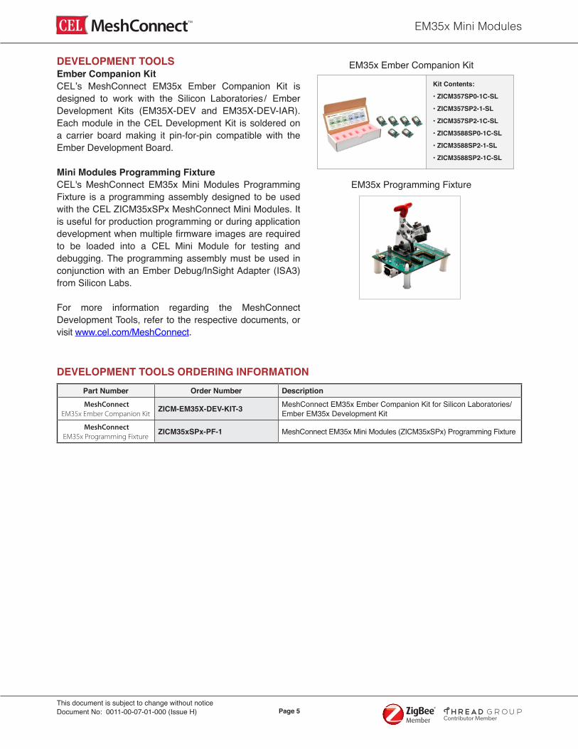
DEVELOPMENT TOOLSEmber Companion KitCEL’s MeshConnect EM35x Ember Companion Kit is designed to work with the Silicon Laboratories/ Ember Development Kits (EM35X-DEV and EM35X-DEV-IAR). Each module in the CEL Development Kit is soldered on a carrier board making it pin-for-pin compatible with the Ember Development Board.
Mini Modules Programming FixtureCEL's MeshConnect EM35x Mini Modules Programming Fixture is a programming assembly designed to be used with the CEL ZICM35xSPx MeshConnect Mini Modules. It is useful for production programming or during application development when multiple firmware images are required to be loaded into a CEL Mini Module for testing and debugging. The programming assembly must be used in conjunction with an Ember Debug/InSight Adapter (ISA3) from Silicon Labs.
For more information regarding the MeshConnect Development Tools, refer to the respective documents, or visit www.cel.com/MeshConnect.
EM35x Programming Fixture
DEVELOPMENT TOOLS ORDERING INFORMATIONPart Number Order Number Description MeshConnect
EM35x Ember Companion KitZICM-EM35X-DEV-KIT-3 MeshConnect EM35x Ember Companion Kit for Silicon Laboratories/
Ember EM35x Development Kit MeshConnect
EM35x Programming FixtureZICM35xSPx-PF-1 MeshConnect EM35x Mini Modules (ZICM35xSPx) Programming Fixture
EM35x Ember Companion Kit
Kit Contents:
• ZICM357SP0-1C-SL
• ZICM357SP2-1-SL
• ZICM357SP2-1C-SL
• ZICM3588SP0-1C-SL
• ZICM3588SP2-1-SL
• ZICM3588SP2-1C-SL

EM35x Mini Modules
Page 6This document is subject to change without noticeDocument No: 0011-00-07-01-000 (Issue H)
Contributor Member
TRANSCEIVER ICCEL’s MeshConnect EM35x Mini Modules use the Ember EM35x transceiver (EM357 or EM358x) IC. The IC incorporates a RF transceiver with baseband modem, a hardwired MAC and an embedded ARM® Cortex™-M3 microcontroller, offering an excellent low cost, high performance solution for all IEEE 802.15.4/ZigBee/Thread applications. For more information about the EM35x IC, visit www.silabs.com.
ANTENNACEL’s MeshConnect EM35x Mini Modules include an integrated Printed Circuit Board (PCB) trace antenna. An optional configuration which uses a castellation pin on the module allows the user to connect an external antenna. The ZICM35xSP0 has been certified with the PCB trace antenna and two external antennas (E-2820-CA, LSR 001-0100). The ZICM35xSP2 has been certified with the PCB trace antenna and a Nearson half-wave dipole antenna (part number: S181AH-2450S) on a 4 inch cable using the castellation pin of the module. Please refer to the document Mini Module External Antenna Implementation for details describing the requirements that must be followed to take advantage of the CEL certification. See Ordering Information on Page 3.
The PCB antenna employs a topology that is compact and highly efficient. To maximize range, an adequate ground plane must be provided on the host PCB. Correctly positioned, the ground plane on the host PCB will contribute significantly to the antenna performance (it should not be directly under the module PCB Antenna). The position of the module on the host board and overall design of the product enclosure contribute to antenna performance. Poor design affects radiation patterns and can result in reflection, diffraction and/or scattering of the transmitted signal.
For optimum antenna performance, the MeshConnect Modules should be mounted with the PCB trace antenna overhanging the edge of the host board. To further improve performance, a ground plane may be placed on the host board under the module, up to the antenna (a minimum of 1.5" x 1.5" is recommended). The installation of an uninterrupted ground plane on a layer directly beneath the module will also allow you to run traces under this layer. CEL can provide assistance with your PCB layout.
The following are some design guidelines to help ensure antenna performance:
• Never place the ground plane or route copper traces directly underneath the antenna portion of the module • Never place the antenna close to metallic objects • In the overall design, ensure that wiring and other components are not placed near the antenna • Do not place the antenna in a metallic or metalized plastic enclosure • Keep plastic enclosures 1cm or more away from the antenna in any direction This radio transmitter IC: 8254A-ZICM357SP0 & IC: 8254A-ZICM357SP2 has been approved by IC Canada to operate with the antenna types listed above with the maximum permissible gain of 2dBi. Antenna types not included in this list, having a gain greater than the maximum gain indicated for that type, are strictly prohibited for use with this device.
Cet émetteur radio IC: 8254A-ZICM357SP0 & IC: 8254A-ZICM357SP2 a été approuvé par IC Canada pour fonctionner avec les types d'antenne énumérés ci-dessus avec le gain maximal admissible de 2dBi. Types d'antennes non inclus dans cette liste, ayant un gain supérieur au gain maximum indiqué pour ce type, sont strictement interdits pour une utilisation avec cet appareil.
POWER AMPLIFIERCEL’s MeshConnect EM35x High Power Mini Module (ZICM35xSP2) includes a Power Amplifier (PA). This PA delivers high efficiency, high gain and high output power (Pout = +20.0dBm typical) to provide an extended range and reliable transmission for fewer nodes in a network. For the ZICM35xSP2, Power Mode 2 with Power Setting -2 is the maximum setting allowed for FCC Compliance. Operating in Power Mode 3 at higher power settings may damage the PA.

EM35x Mini Modules
Page 7This document is subject to change without noticeDocument No: 0011-00-07-01-000 (Issue H)
Contributor Member
USBThe ZICM3588SPx-x Modules have an integrated USB 2.0-compliant, full-speed (12Mbps) device peripheral. For more information, refer to the EM35x SoC Datasheet link provided in the References Section of this document.
SOFTWARE/FIRMWARECEL’s MeshConnect EM35x Mini Modules are ideal platforms for EmberZNet PRO, the industry’s most deployed and field proven ZigBee compliant stack supporting the ZigBee PRO feature set. EmberZNet PRO is a complete ZigBee protocol software package containing all the elements required for mesh networking applications. The ZICM3588SPx variants are also ideal platforms for Thread, an IP-based mesh networking stack that allows direct IPv6 connectivity to all devices within the network. For more information regarding the software development for the EM35x IC family, visit www.silabs.com.
CEL provides reference software that runs multiple functions and executes various commands. For example, users can set up a simple ZigBee network to perform Range and Packet Error Rate (PER) tests between two devices. This allows the user to evaluate the module's RF performance in their own environment. The software can also place the module in various operating modes which allows for testing of low-level RF performance, GPIO functionality, etc.
The ZICM35xSP0 Module uses the transceiver's primary RF ports for transmitting and should use Power Mode 1 (EMBER_TX_POWER_MODE_BOOST in the EmberZNet API).
The ZICM35xSP2 Module uses the transceiver's alternate RF ports for transmitting and should use Power Mode 2 (EMBER_TX_POWER_MODE_ALTERNATE in the EmberZNet API). GPIO PC5 must also be configured as ALT_OUT (push/pull).
EM35x Mini Modules
Page 8This document is subject to change without noticeDocument No: 0011-00-07-01-000 (Issue H)
Contributor Member
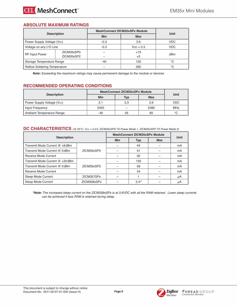
ABSOLUTE MAXIMUM RATINGS
DescriptionMeshConnect ZICM35xSPx Module
UnitMin Max
Power Supply Voltage (VDD) -0.3 3.6 VDCVoltage on any I /O Line -0.3 VDD + 0.3 VDC
RF Input Power ZICM35xSP0 ZICM35xSP2
– –
+15+5 dBm
Storage Temperature Range -40 125 °CReflow Soldering Temperature – 260 °C
Note: Exceeding the maximum ratings may cause permanent damage to the module or devices.
RECOMMENDED OPERATING CONDITIONS
DescriptionMeshConnect ZICM35xSPx Module
UnitMin Typ Max
Power Supply Voltage (VDD) 2.1 3.3 3.6 VDCInput Frequency 2405 – 2480 MHzAmbient Temperature Range -40 25 85 °C
DC CHARACTERISTICS (@ 25°C, VDD = 3.3V, ZICM35xSP0 TX Power Mode 1, ZICM35xSP2 TX Power Mode 2)
DescriptionMeshConnect ZICM35xSPx Module
UnitMin Typ Max
Transmit Mode Current @ +8dBmZICM35xSP0
– 44 – mATransmit Mode Current @ 0dBm – 31 – mAReceive Mode Current – 30 – mATransmit Mode Current @ +20dBm
ZICM35xSP2– 150 – mA
Transmit Mode Current @ 0dBm – 58 – mAReceive Mode Current – 34 – mASleep Mode Current ZICM357SPx – 1 – µASleep Mode Current ZICM358xSPx – 2.4* – µA
*Note: The increased sleep current on the ZICM358xSPx is at 3.6VDC with all the RAM retained. Lower sleep currents can be achieved if less RAM is retained during sleep.
EM35x Mini Modules
Page 9This document is subject to change without noticeDocument No: 0011-00-07-01-000 (Issue H)
Contributor Member
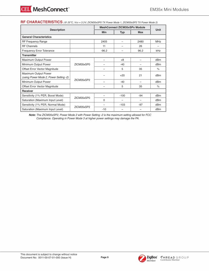
RF CHARACTERISTICS (@ 25°C, VDD = 3.3V, ZICM35xSP0 TX Power Mode 1, ZICM35xSP2 TX Power Mode 2)
DescriptionMeshConnect ZICM35xSPx Module
UnitMin Typ Max
General CharacteristicsRF Frequency Range 2405 – 2480 MHzRF Channels 11 – 26 –Frequency Error Tolerance -96.2 – 96.2 kHzTransmitterMaximum Output Power
ZICM35xSP0– +8 – dBm
Minimum Output Power – -40 – dBmOffset Error Vector Magnitude – 5 35 %Maximum Output Power (using Power Mode 2, Power Setting -2)
ZICM35xSP2– +20 21 dBm
Minimum Output Power – -40 – dBmOffset Error Vector Magnitude – 5 35 %Receiver Sensitivity (1% PER, Boost Mode)
ZICM35xSP0– -100 -94 dBm
Saturation (Maximum Input Level) 0 – – dBmSensitivity (1% PER, Normal Mode)
ZICM35xSP2– -103 -97 dBm
Saturation (Maximum Input Level) -10 – – dBm
Note: The ZICM35xSP2, Power Mode 2 with Power Setting -2 is the maximum setting allowed for FCC Compliance. Operating in Power Mode 3 at higher power settings may damage the PA.
EM35x Mini Modules
Page 10This document is subject to change without noticeDocument No: 0011-00-07-01-000 (Issue H)
Contributor Member
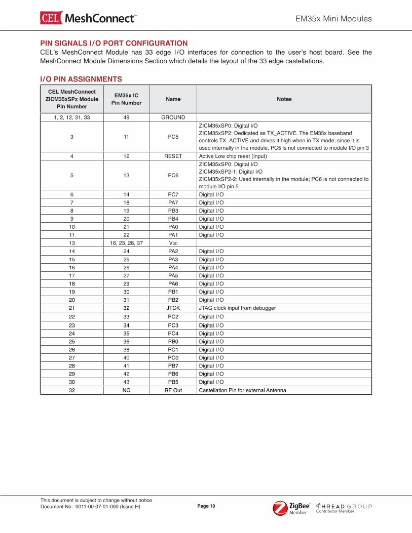
PIN SIGNALS I /O PORT CONFIGURATIONCEL’s MeshConnect Module has 33 edge I /O interfaces for connection to the user’s host board. See the MeshConnect Module Dimensions Section which details the layout of the 33 edge castellations. I /O PIN ASSIGNMENTS
CEL MeshConnect ZICM35xSPx Module
Pin Number
EM35x IC Pin Number Name Notes
1, 2, 12, 31, 33 49 GROUND
3 11 PC5
ZICM35xSP0: Digital I/OZICM35xSP2: Dedicated as TX_ACTIVE. The EM35x baseband controls TX_ACTIVE and drives it high when in TX mode; since it is used internally in the module, PC5 is not connected to module I/O pin 3
4 12 RESET Active Low chip reset (Input)
5 13 PC6
ZICM35xSP0: Digital I/O ZICM35xSP2-1: Digital I/OZICM35xSP2-2: Used internally in the module; PC6 is not connected to module I/O pin 5
6 14 PC7 Digital I /O7 18 PA7 Digital I /O8 19 PB3 Digital I /O9 20 PB4 Digital I /O
10 21 PA0 Digital I /O11 22 PA1 Digital I /O13 16, 23, 28, 37 VDD
14 24 PA2 Digital I /O15 25 PA3 Digital I /O16 26 PA4 Digital I /O17 27 PA5 Digital I /O18 29 PA6 Digital I /O19 30 PB1 Digital I /O20 31 PB2 Digital I /O21 32 JTCK JTAG clock input from debugger22 33 PC2 Digital I /O23 34 PC3 Digital I /O24 35 PC4 Digital I /O25 36 PB0 Digital I /O26 38 PC1 Digital I /O27 40 PC0 Digital I /O28 41 PB7 Digital I /O29 42 PB6 Digital I /O30 43 PB5 Digital I /O32 NC RF Out Castellation Pin for external Antenna
EM35x Mini Modules
Page 11This document is subject to change without noticeDocument No: 0011-00-07-01-000 (Issue H)
Contributor Member
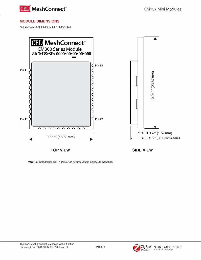
MODULE DIMENSIONS
Note: All dimensions are +/- 0.005" (0.12mm) unless otherwise specified.
0.655” (16.63mm)
0.94
0” (2
3.87
mm
)
R6
R7
U1
R1
C7 C7B
L4
L3
C11R10
C21 C2
0
L5
R11 C23
C22
R8C5B
C24
C13
C6A C1
C2
R5
L6C6B
C6L2
C14
C10
C9 R2
R9
C15
C16
R4C17
C4A
XTAL1
0.062” (1.57mm)0.152” (3.86mm) MAX
EM357
SeriesARM
R6
R7
U1
R1
C7 C7B
L4
L3
C11R10
C21 C2
0
L5
R11 C23
C22
R8C5B
C24
C13
C6A C1
C2
R5
L6C6B
C6L2
C14
C10
C9 R2
R9
C15
C16
R4C17
C4A
XTAL1
EM357
SeriesARM
0000-00-00-00-000EM300 Series Module
ZICM35xSPx
Pin 1
Pin 11 Pin 22
Pin 33
MeshConnect EM35x Mini Modules
EM35x Mini Modules
Page 12This document is subject to change without noticeDocument No: 0011-00-07-01-000 (Issue H)
Contributor Member
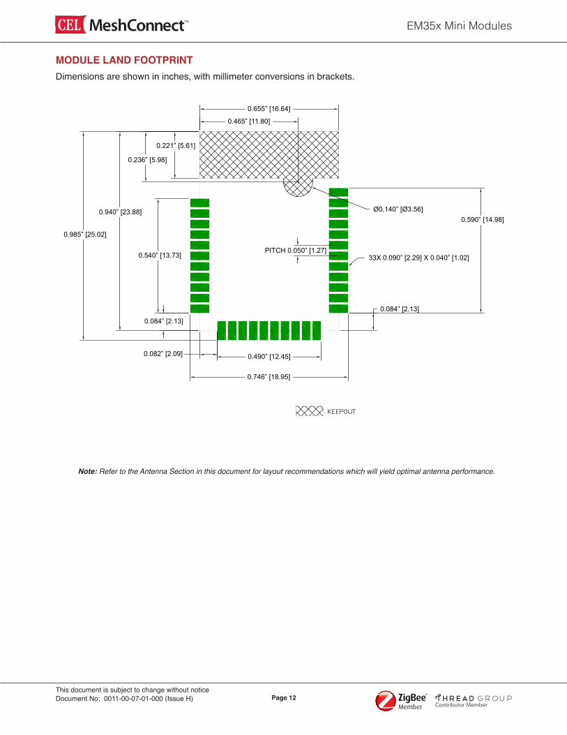
MODULE LAND FOOTPRINT
0.655” [16.64]
0.465” [11.80]
0.221” [5.61]
0.236” [5.98]
0.940” [23.88]
0.985” [25.02]
0.540” [13.73]PITCH 0.050” [1.27]
0.084” [2.13]
0.082” [2.09] 0.490” [12.45]
0.746” [18.95]
0.084” [2.13]
33X 0.090” [2.29] X 0.040” [1.02]
Ø0.140” [Ø3.56]0.590” [14.98]
Note: Refer to the Antenna Section in this document for layout recommendations which will yield optimal antenna performance.
Dimensions are shown in inches, with millimeter conversions in brackets.
EM35x Mini Modules
Page 13This document is subject to change without noticeDocument No: 0011-00-07-01-000 (Issue H)
Contributor Member
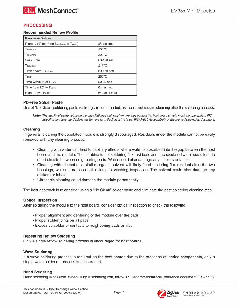
PROCESSING Recommended Reflow Profile
Parameter ValuesRamp Up Rate (from Tsoakmax to Tpeak) 3º/sec maxTsoakmin 150ºC Tsoakmax 200ºCSoak Time 60-120 secTLiquidus 217ºC Time above TLiquidus 60-150 secTpeak 250ºCTime within 5º of Tpeak 20-30 secTime from 25º to Tpeak 8 min maxRamp Down Rate 6ºC/sec max
Pb-Free Solder PasteUse of “No Clean” soldering paste is strongly recommended, as it does not require cleaning after the soldering process. Note: The quality of solder joints on the castellations ("half vias") where they contact the host board should meet the appropriate IPC Specification. See the Castellated Terminations Section in the latest IPC-A-610 Acceptability of Electronic Assemblies document.
CleaningIn general, cleaning the populated module is strongly discouraged. Residuals under the module cannot be easily removed with any cleaning process.
• Cleaning with water can lead to capillary effects where water is absorbed into the gap between the host board and the module. The combination of soldering flux residuals and encapsulated water could lead to short circuits between neighboring pads. Water could also damage any stickers or labels. • Cleaning with alcohol or a similar organic solvent will likely flood soldering flux residuals into the two housings, which is not accessible for post-washing inspection. The solvent could also damage any stickers or labels. • Ultrasonic cleaning could damage the module permanently. The best approach is to consider using a “No Clean” solder paste and eliminate the post-soldering cleaning step.
Optical InspectionAfter soldering the module to the host board, consider optical inspection to check the following:
• Proper alignment and centering of the module over the pads • Proper solder joints on all pads • Excessive solder or contacts to neighboring pads or vias
Repeating Reflow SolderingOnly a single reflow soldering process is encouraged for host boards.
Wave SolderingIf a wave soldering process is required on the host boards due to the presence of leaded components, only a single wave soldering process is encouraged.
Hand SolderingHand soldering is possible. When using a soldering iron, follow IPC recommendations (reference document IPC-7711).

EM35x Mini Modules
Page 14This document is subject to change without noticeDocument No: 0011-00-07-01-000 (Issue H)
Contributor Member
ReworkThe MeshConnect Module can be unsoldered from the host board. Use of a hot air rework tool should be programmable and the solder joint and module should not exceed the maximum peak reflow temperature of 250ºC. CautionIf temperature ramps exceed the reflow temperature profile, module and component damage may occur due to thermal shock. Avoid overheating. WarningNever attempt a rework on the module itself (i.e., replacing individual components); such actions will terminate warranty coverage.
Additional GroundingAttempts to improve the module or the system grounding by soldering braids, wires or cables onto the module RF shield cover is done at the customer's own risk. The ground pins at the module perimeter should be sufficient for optimum immunity to external RF interference.

EM35x Mini Modules
Page 15This document is subject to change without noticeDocument No: 0011-00-07-01-000 (Issue H)
Contributor Member
AGENCY CERTIFICATIONSThe following Part Numbers are Certified as shown below:
Part Number Certifications AntennaZICM35xSP0-1 FCC, IC, CE PCBZICM35xSP0-1C FCC, IC, CE E-2820-CA, LSR 001-0100ZICM35xSP2-x FCC, IC PCBZICM35xSP2-xC FCC, IC Nearson S181AH-2450S
FCC and Canada Compliance StatementThis device complies with Part 15 of the FCC Rules and with IC Canada licence-exempt RSS Standards. Operation is subject to the following two conditions:
1. This device may not cause harmful interference, and 2. This device must accept any interference received, including interference that may cause undesired operation.
Déclaration De Conformité FCC Et Au CanadaLe présent appareil est conforme aux CNR d'Industrie Canada applicables aux appareils radio exempts de licence. L'exploitation est autorisée aux deux conditions suivantes:
1. l'appareil ne doit pas produire de brouillage, et 2. l'utilisateur de l'appareil doit accepter tout brouillage radioélectrique subi, même si le brouillage est susceptible d'en compromettre le fonctionnement. Warning (Part 15.21)Changes or modifications not expressly approved by CEL could void the user's authority to operate the equipment. 20cm Separation DistanceTo comply with FCC/IC Canada RF exposure limits for general population/uncontrolled exposure, the antenna(s) used for this transmitter must be installed to provide a separation distance of at least 20cm from all persons and must not be co-located or operated in conjunction with any other antenna or transmitter except in accordance with FCC muti-transmitter product procedures.
20cm Distance De SéparationPour se conformer aux limites d'exposition FCC / IC Canada RF pour la population générale / exposition non contrôlée, l'antenne(s) utilisée pour ce transmetteur doit être installé pour fournir une distance de séparation d'au moins 20cm de toutes les personnes et ne doit pas être co-implantés ou exploités en conjonction avec une autre antenne ou émetteur, sauf en conformité avec les procédures de produits muti-émetteur FCC.
OEM Responsibility to the FCC and IC Rules and Regulations The MeshConnect Mini Module has been certified per FCC Part 15 Rules and to IC Canada license-exempt RSS Standards for integration into products without further testing or certification. To fulfill the FCC and IC Certification requirements, the OEM of the MeshConnect Module must ensure that the information provided on the MeshConnect label is placed on the outside of the final product. The MeshConnect Mini Module is labeled with its own FCC ID Number and IC ID Number. If the FCC ID and the IC ID are not visible when the module is installed inside another device, then the outside of the device into which the module is installed must also display a label referring to the enclosed module. The exterior label can use wording such as the following:

EM35x Mini Modules
Page 16This document is subject to change without noticeDocument No: 0011-00-07-01-000 (Issue H)
Contributor Member
“Contains Transmitter Module FCC ID: W7Z-ZICM357SP0” or “Contains FCC ID: W7Z-ZICM357SP0” “Contains Transmitter Module IC: 8254A-ZICM357SP0" or "Contains IC: 8254A-ZICM357SP0”or “Contains Transmitter Module FCC ID: W7Z-ZICM357SP2” or “Contains FCC ID: W7Z-ZICM357SP2” “Contains Transmitter Module IC: 8254A-ZICM357SP2" or "Contains IC: 8254A-ZICM357SP2”
The OEM of the MeshConnect Mini Module may only use the approved antennas (PCB Trace Antenna and external antenna) that have been certified with this module. The OEM of the MeshConnect Mini Module must test their final product configuration to comply with Unintentional Radiator Limits before declaring FCC Compliance per Part 15 of the FCC Rules. The OEM must also include in their manual the following statement:
FCC and Canada Compliance StatementThis device complies with Part 15 of the FCC Rules and with IC Canada licence-exempt RSS Standards. Operation is subject to the following two conditions:
1. This device may not cause harmful interference, and 2. This device must accept any interference received, including interference that may cause undesired operation.
Déclaration De Conformité FCC Et Au CanadaLe présent appareil est conforme aux CNR d'Industrie Canada applicables aux appareils radio exempts de licence. L'exploitation est autorisée aux deux conditions suivantes:
1. l'appareil ne doit pas produire de brouillage, et 2. l'utilisateur de l'appareil doit accepter tout brouillage radioélectrique subi, même si le brouillage est susceptible d'en compromettre le fonctionnement.
In addition to using only the approved external antennas, the OEM must follow the layout described in the "Mini Module External Antenna Implementation Guide" to be covered by the current approval.
CE Certification — EuropeThe MeshConnect ZICM35xSP0 Module has been tested and certified for use in the European Union.
OEM Responsibility to the European Union Compliance Rules If the MeshConnect Module is to be incorporated into a product, the OEM must verify compliance of the final product to the European Harmonized EMC and Low-Voltage/Safety Standards. A Declaration of Conformity must be issued for each of these standards and kept on file as described in Annex II of the R&TTE Directive.
The manufacturer must maintain the user guide and adhere to the settings described in the manual for maintaining European Union Compliance. If any of the specifications are exceeded in the final product, the OEM is required tomake a submission to the notified body for compliance testing.
EM35x Mini Modules
Page 17This document is subject to change without noticeDocument No: 0011-00-07-01-000 (Issue H)
Contributor Member
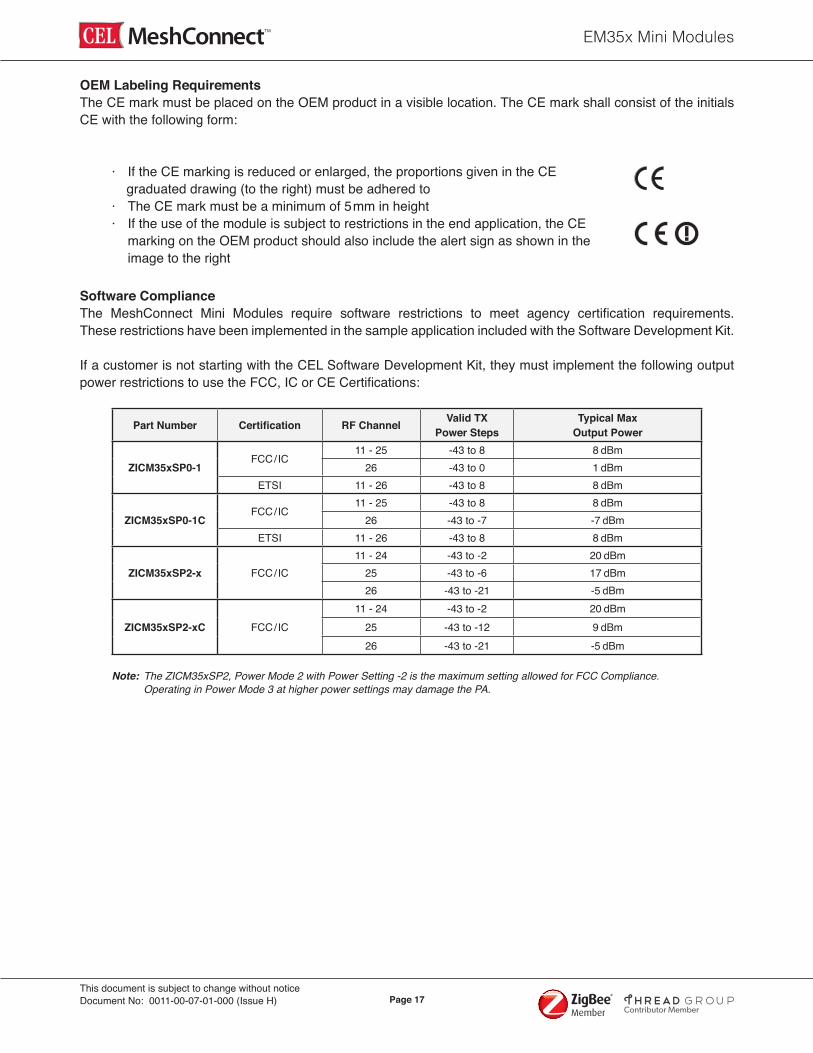
OEM Labeling RequirementsThe CE mark must be placed on the OEM product in a visible location. The CE mark shall consist of the initials CE with the following form:
· If the CE marking is reduced or enlarged, the proportions given in the CE graduated drawing (to the right) must be adhered to · The CE mark must be a minimum of 5mm in height · If the use of the module is subject to restrictions in the end application, the CE marking on the OEM product should also include the alert sign as shown in the image to the right
Software ComplianceThe MeshConnect Mini Modules require software restrictions to meet agency certification requirements. These restrictions have been implemented in the sample application included with the Software Development Kit. If a customer is not starting with the CEL Software Development Kit, they must implement the following output power restrictions to use the FCC, IC or CE Certifications:
Part Number Certification RF Channel Valid TX Power Steps
Typical Max Output Power
ZICM35xSP0-1FCC/IC
11 - 25 -43 to 8 8 dBm26 -43 to 0 1 dBm
ETSI 11 - 26 -43 to 8 8 dBm
ZICM35xSP0-1CFCC/IC
11 - 25 -43 to 8 8 dBm26 -43 to -7 -7 dBm
ETSI 11 - 26 -43 to 8 8 dBm
ZICM35xSP2-x FCC/IC11 - 24 -43 to -2 20 dBm
25 -43 to -6 17 dBm26 -43 to -21 -5 dBm
ZICM35xSP2-xC FCC/IC11 - 24 -43 to -2 20 dBm
25 -43 to -12 9 dBm26 -43 to -21 -5 dBm
Note: The ZICM35xSP2, Power Mode 2 with Power Setting -2 is the maximum setting allowed for FCC Compliance. Operating in Power Mode 3 at higher power settings may damage the PA.
EM35x Mini Modules
Page 18This document is subject to change without noticeDocument No: 0011-00-07-01-000 (Issue H)
Contributor Member
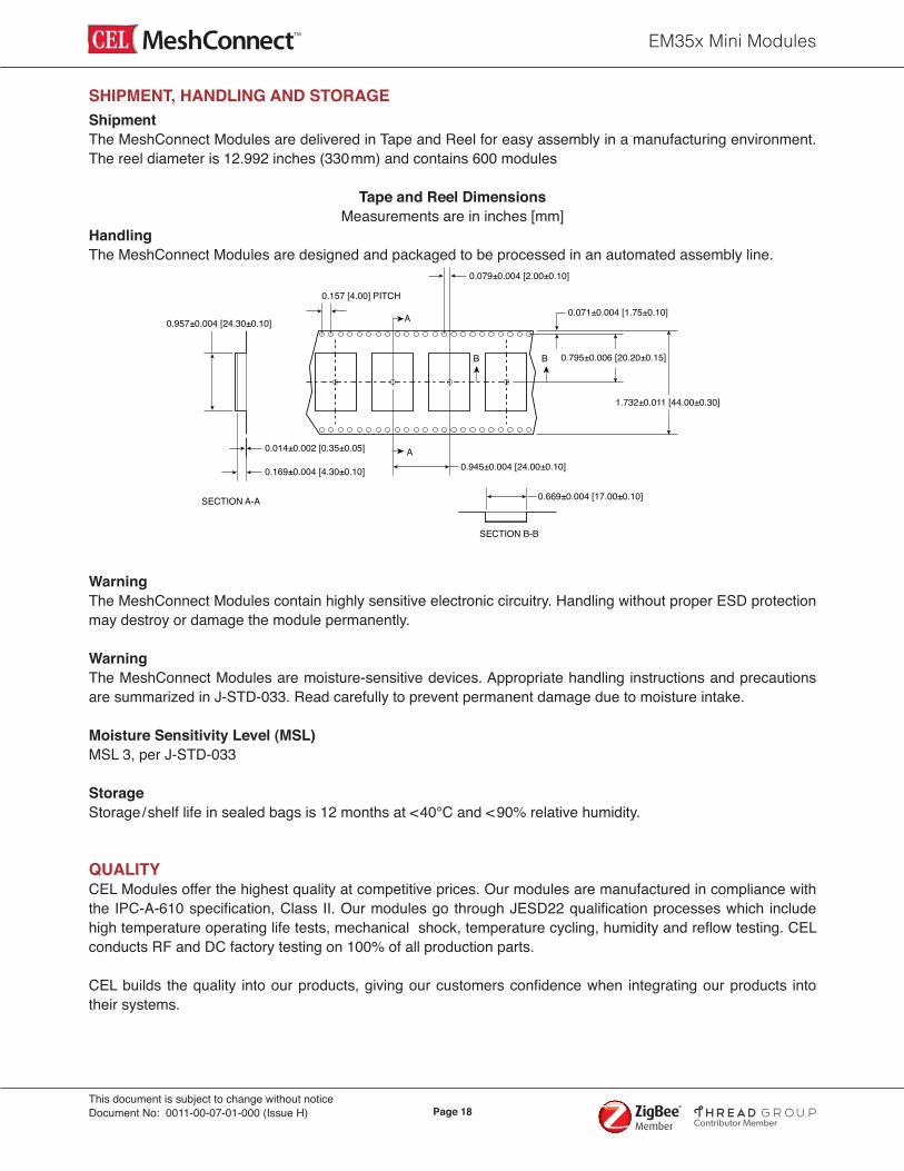
ShipmentThe MeshConnect Modules are delivered in Tape and Reel for easy assembly in a manufacturing environment. The reel diameter is 12.992 inches (330mm) and contains 600 modules
Tape and Reel DimensionsMeasurements are in inches [mm]
HandlingThe MeshConnect Modules are designed and packaged to be processed in an automated assembly line.
WarningThe MeshConnect Modules contain highly sensitive electronic circuitry. Handling without proper ESD protection may destroy or damage the module permanently.
WarningThe MeshConnect Modules are moisture-sensitive devices. Appropriate handling instructions and precautions are summarized in J-STD-033. Read carefully to prevent permanent damage due to moisture intake.
Moisture Sensitivity Level (MSL)MSL 3, per J-STD-033 StorageStorage/shelf life in sealed bags is 12 months at <40°C and < 90% relative humidity.
QUALITYCEL Modules offer the highest quality at competitive prices. Our modules are manufactured in compliance with the IPC-A-610 specification, Class II. Our modules go through JESD22 qualification processes which include high temperature operating life tests, mechanical shock, temperature cycling, humidity and reflow testing. CEL conducts RF and DC factory testing on 100% of all production parts. CEL builds the quality into our products, giving our customers confidence when integrating our products into their systems.
SHIPMENT, HANDLING AND STORAGE
0.079±0.004 [2.00±0.10]
0.071±0.004 [1.75±0.10]
0.795±0.006 [20.20±0.15]
1.732±0.011 [44.00±0.30]
0.014±0.002 [0.35±0.05]
0.957±0.004 [24.30±0.10]
0.169±0.004 [4.30±0.10] 0.945±0.004 [24.00±0.10]
0.669±0.004 [17.00±0.10]SECTION A-A
A
A
0.157 [4.00] PITCH
SECTION B-B
B B
EM35x Mini Modules
Page 19This document is subject to change without noticeDocument No: 0011-00-07-01-000 (Issue H)
Contributor Member
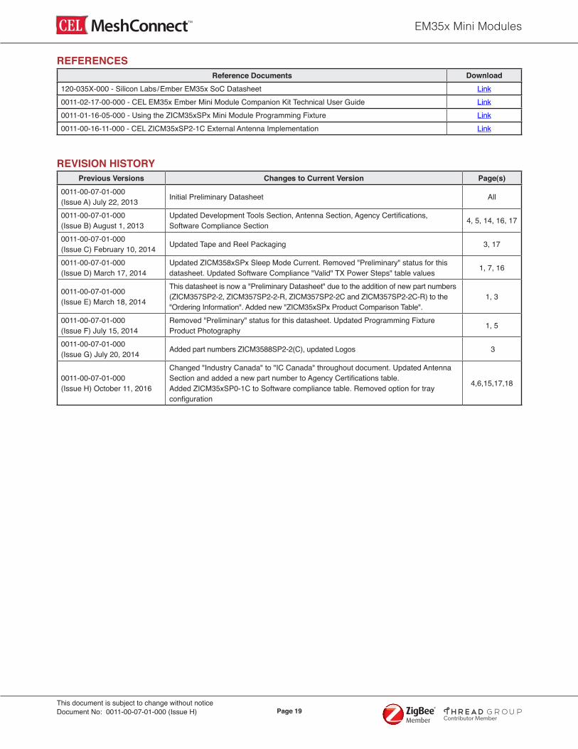
REFERENCES Reference Documents Download
120-035X-000 - Silicon Labs/Ember EM35x SoC Datasheet Link0011-02-17-00-000 - CEL EM35x Ember Mini Module Companion Kit Technical User Guide Link0011-01-16-05-000 - Using the ZICM35xSPx Mini Module Programming Fixture Link0011-00-16-11-000 - CEL ZICM35xSP2-1C External Antenna Implementation Link
REVISION HISTORYPrevious Versions Changes to Current Version Page(s)
0011-00-07-01-000 (Issue A) July 22, 2013 Initial Preliminary Datasheet All
0011-00-07-01-000 (Issue B) August 1, 2013
Updated Development Tools Section, Antenna Section, Agency Certifications, Software Compliance Section 4, 5, 14, 16, 17
0011-00-07-01-000 (Issue C) February 10, 2014 Updated Tape and Reel Packaging 3, 17
0011-00-07-01-000 (Issue D) March 17, 2014
Updated ZICM358xSPx Sleep Mode Current. Removed "Preliminary" status for this datasheet. Updated Software Compliance "Valid" TX Power Steps" table values 1, 7, 16
0011-00-07-01-000 (Issue E) March 18, 2014
This datasheet is now a "Preliminary Datasheet" due to the addition of new part numbers (ZICM357SP2-2, ZICM357SP2-2-R, ZICM357SP2-2C and ZICM357SP2-2C-R) to the "Ordering Information". Added new "ZICM35xSPx Product Comparison Table".
1, 3
0011-00-07-01-000 (Issue F) July 15, 2014
Removed "Preliminary" status for this datasheet. Updated Programming Fixture Product Photography 1, 5
0011-00-07-01-000 (Issue G) July 20, 2014 Added part numbers ZICM3588SP2-2(C), updated Logos 3
0011-00-07-01-000 (Issue H) October 11, 2016
Changed "Industry Canada" to "IC Canada" throughout document. Updated Antenna Section and added a new part number to Agency Certifications table.Added ZICM35xSP0-1C to Software compliance table. Removed option for tray configuration
4,6,15,17,18

EM35x Mini Modules
Page 20This document is subject to change without noticeDocument No: 0011-00-07-01-000 (Issue H)
Contributor Member
The information in this document is current as of the published date. The information is subject to change without notice. For actual design-in, refer to the latest publications of CEL Data Sheets or Data Books, etc., for the most up-to-date specifications of CEL products. Not all products and/or types are available in every country. Please check with an CEL sales representative for availability and additional information. No part of this document may be copied or reproduced in any form or by any means without the prior written consent of CEL. CEL assumes no responsibility for any errors that may appear in this document. CEL does not assume any liability for infringement of patents, copyrights or other intellectual property rights of third parties by or arising from the use of CEL products listed in this document or any other liability arising from the use of such products. No license, express, implied or otherwise, is granted under any patents, copyrights or other intellectual property rights of CEL or others. Descriptions of circuits, software and other related information in this document are provided for illustrative purposes in semiconductor product operation and application examples. The incorporation of these circuits, software and information in the design of a customer’s equipment shall be done under the full responsibility of the customer. CEL assumes no responsibility for any losses incurred by customers or third parties arising from the use of these circuits, software and information. While CEL endeavors to enhance the quality, reliability and safety of CEL products, customers agree and acknowledge that the possibility of defects thereof cannot be eliminated entirely. To minimize risks of damage to property or injury (including death) to persons arising from defects in CEL products, customers must incorporate sufficient safety measures in their design, such as redundancy, fire-containment and anti-failure features.
Disclaimer
For More Information For more information about CEL MeshConnect products and solutions, visit our website at: www.cel.com/MeshConnect.
Technical AssistanceFor Technical Assistance, visit www.cel.com/MeshConnectHelp.