Embed Size (px)
Citation preview
AUTOMATIC POWER
FACTOR CORRECTIONmertech
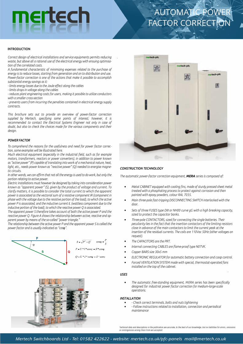
INTRODUCTION
Correct design of electrical installations and service equipments permits reducing waste, but above all a rational use of the electrical energy with ensuing optimisa-tion of the correlated costs.A fundamental characteristic of minimizing expenses related to the purchase of energy is to reduce losses, starting from generation and on to distribution and use. Power-factor correction is one of the actions that make it possible to accomplish substantial energy savings as it:- limits energy losses due to the Joule effect along the cables- limits drops in voltage along the cables- reduces plant engineering costs for users, making it possible to utilize conductors with a smaller cross-section- prevents users from incurring the penalties contained in electrical energy supply contracts.
This brochure sets out to provide an overview of power-factor correction supplied by Mertech, specifying some points of interest; however, it is recommended to contact the Electrical Systems Engineer not only in case of doubt, but also to check the choices made for the various components and their design.
POWER FACTOR
To comprehend the reasons for the usefulness and need for power factor correc-tion, some examples will be illustrated here.Much electrical equipment (especially in the industrial field, such as for example motors, transformers, reactors or power converters), in addition to power known as active power (P) capable of translating into work of a mechanical nature, heat, light, etc., needs power known as reactive power (Q) needed to energise magne-tic circuits.In other words, we can affirm that not all the energy is used to do work, but only the portion relating to active power.Electric installations must however be designed by taking into consideration power known as apparent power (S), given by the product of voltage and current. To clarify matters, it is possible to consider the total current to which the apparent power is associated as the vectorial sum of a resistive component IR (component in phase with the voltage due to the resistive portion of the load), to which the active power P is associated, and the inductive current IL (wattless component due to the inductive portion of the load), to which the reactive power Q is associated.The apparent power S therefore takes account of both the active power P and the reactive power Q. Figure A shows the relationship between active, reactive and ap-parent power by means of the so-called power triangle.The relationship between the active power P and the apparent power S is called the power factor and is usually indicated as cos .
CONSTRUCTION TECHNOLOGY
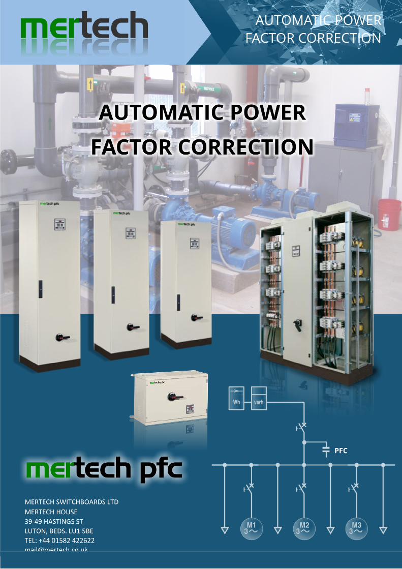
The automatic power-factor correction equipment, MERA series is composed of:
Metal CABINET equipped with cooling fins, made of sturdy pressed sheet metal treated with a phosphating process to protect against corrosion and then painted with epoxy powders, colour RAL 7035.
Main three-pole fast-tripping DISCONNECTING SWITCH interlocked with the door.
Sets of three FUSES type DIII or NH00 curve gG with a high breaking capacity, sized to protect the capacitor banks.
Three-pole CONTACTORS, sized for connecting the single batteries. Their peculiarity lies in the fact that the insertion contactors of the limiting resistors close in advance of the main contactors to limit the current peak at the insertion of the residual currents. The coils are 110Vac 50Hz (other voltages on request).
The CAPACITORS are the PRT.
Internal connecting CABLES are flame-proof type N07VK.
Copper BARS size 30x5 mm
ELECTRONIC REGULATOR for automatic battery connection and cos control.
Forced VENTILATION SYSTEM made with special, thermostat-operated fans installed on the top of the cabinet.
USES
The automatic free-standing equipment, MERA series has been specifically designed for industrial power factor correction for medium-large-scale operations.
INSTALLATION
- Check correct terminals, bolts and nuts tightening- Follow instructions related to installation, connection and periodical maintenance
AUTOMATIC POWER
FACTOR CORRECTIONmertech
Mertech Switchboards Ltd - Tel: 01582 422622 - website: mertech.co.uk/pfc-panels [email protected]
L3
L 2
L1
L3
L 2
L1
4AU36
L3
L 2
L1
L3
L 2
L1
L3
L 2
L1
L3
L 2
L1
C PR7plus A U TO M AT I C P OW E R F AC T OR RE G UL A TO R
AUTMA
NMO DE + -
AUTOMATIC POWER
FACTOR CORRECTIONmertech
Mertech Switchboards Ltd - Tel: 01582 422622 - website: mertech.co.uk/pfc-panels [email protected]
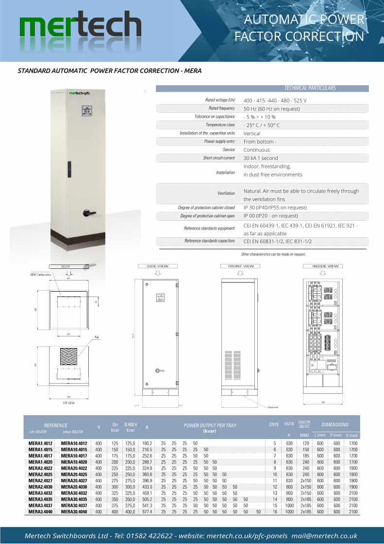
STANDARD AUTOMATIC POWER FACTOR CORRECTION - MERA
400 - 415 -440 - 480 - 525 V
50 Hz (60 Hz on request)
- 5 % ÷ + 10 %
- 25° C / + 50° C
Vertical
From bottom -
Continuous
30 kA 1 second
Indoor, freestanding,
in dust-free environments
Natural. Air must be able to circulate freely through
the ventilation fins
IP 30 (IP40/IP55 on request)
IP 00 (IP20 - on request)
CEI EN 60439-1, IEC 439-1, CEI EN 61921, IEC 921 -
as far as applicable
CEI EN 60831-1/2, IEC 831-1/2
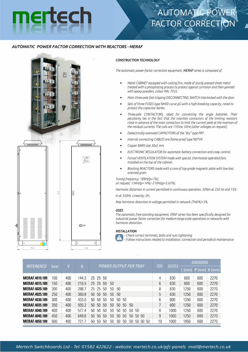
CONSTRUCTION TECHNOLOGY
The automatic power-factor correction equipment, MERAF series is composed of:
Metal CABINET equipped with cooling fins, made of sturdy pressed sheet metal treated with a phosphating process to protect against corrosion and then painted with epoxy powders, colour RAL 7035.
Main three-pole fast-tripping DISCONNECTING SWITCH interlocked with the door.
Sets of three FUSES type NH00 curve gG with a high breaking capacity, rated to protect the capacitor banks.
Three-pole CONTACTORS, rated for connecting the single batteries. Their peculiarity lies in the fact that the insertion contactors of the limiting resistors close in advance of the main contactors to limit the current peak at the insertion of the residual currents. The coils are 110Vac 50Hz (other voltages on request).
Dielectrically oversized CAPACITORS of the dry type PRT.
Internal connecting CABLES are flame-proof type N07VK.
Copper BARS size 30x5 mm
ELECTRONIC REGULATOR for automatic battery connection and cos control.
Forced VENTILATION SYSTEM made with special, thermostat-operated fans installed on the top of the cabinet.
Blocking REACTORS made with a core of top-grade magnetic plate with low-loss oriented grain.
Tuning frequency: 189Hz(p=7%);on request: 134Hz(p=14%) -210Hz(p=5.67%).
Harmonic distortion in current permitted in continuous operation: 30%In at 250 Hz and 15%
In at 350Hz. Linearity: 2In.
Max harmonic distortion in voltage permitted in network (THD%)=5%.
USES
The automatic free-standing equipment, ERAF series has been specifically designed for industrial power factor correction for medium-large-scale operations in networks with harmonic distortion.
INSTALLATION
- Check correct terminals, bolts and nuts tightening- Follow instructions related to installation, connection and periodical maintenance
AUTOMATIC POWER FACTOR CORRECTION WITH REACTORS - MERAF
+ -MODE
CPR7/12 AUTOMATIC POWER
FACTOR REGULATOR
DATAREV.MODIFICAFIRMAIMPIANTORI F.CLIENTESCHETI MATOLOFIRMDI ASEGNA TO RESEGUESCALAN.DISN..ADA RCH.TO TAT. FOGFO LIGLIOElectroGraphicsSrSAN lMARTINODI LUP ARI (PERAF D)PERC ATALOGO.DW29/07/2015 G1:1mmiDEA R. 2006ERAFPERC ATALOG1O
AUTOMATIC POWER
FACTOR CORRECTIONmertech
Mertech Switchboards Ltd - Tel: 01582 422622 - website: mertech.co.uk/pfc-panels [email protected]
AUTOMATIC POWER
FACTOR CORRECTIONmertech
Mertech Switchboards Ltd - Tel: 01582 422622 - website: mertech.co.uk/pfc-panels [email protected]
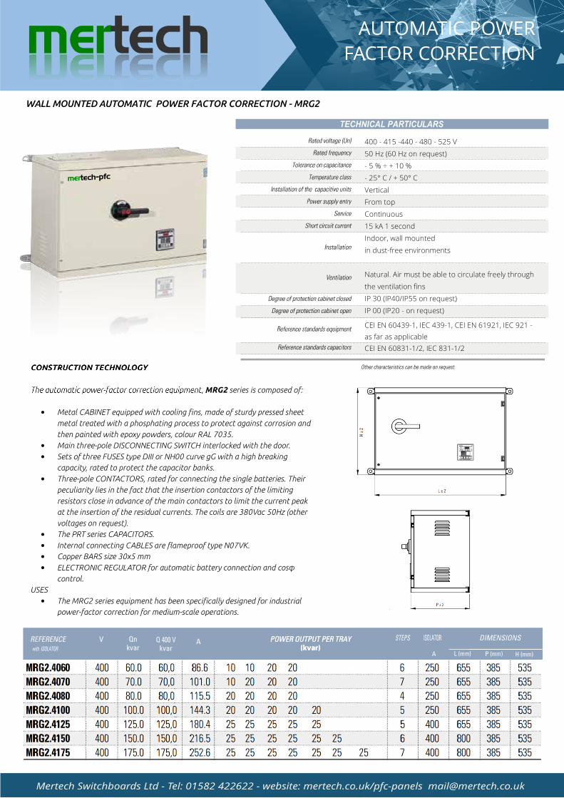
WALL MOUNTED AUTOMATIC POWER FACTOR CORRECTION - MRG2
400 - 415 -440 - 480 - 525 V
50 Hz (60 Hz on request)
- 5 % ÷ + 10 %
- 25° C / + 50° C
Vertical
From top
Continuous
15 kA 1 second
Indoor, wall mounted
in dust-free environments
Natural. Air must be able to circulate freely through
the ventilation fins
IP 30 (IP40/IP55 on request)
IP 00 (IP20 - on request)
CEI EN 60439-1, IEC 439-1, CEI EN 61921, IEC 921 -
as far as applicable
CEI EN 60831-1/2, IEC 831-1/2
CONSTRUCTION TECHNOLOGY
The automatic power-factor correction equipment, MRG2 series is composed of:
Metal CABINET equipped with cooling fins, made of sturdy pressed sheet
metal treated with a phosphating process to protect against corrosion and
then painted with epoxy powders, colour RAL 7035.
Main three-pole DISCONNECTING SWITCH interlocked with the door.
Sets of three FUSES type DIII or NH00 curve gG with a high breaking
capacity, rated to protect the capacitor banks.
Three-pole CONTACTORS, rated for connecting the single batteries. Their
peculiarity lies in the fact that the insertion contactors of the limiting
resistors close in advance of the main contactors to limit the current peak
at the insertion of the residual currents. The coils are 380Vac 50Hz (other
voltages on request).
The PRT series CAPACITORS.
Internal connecting CABLES are flameproof type N07VK.
Copper BARS size 30x5 mm
ELECTRONIC REGULATOR for automatic battery connection and cos
control.
USES
The MRG2 series equipment has been specifically designed for industrial
power-factor correction for medium-scale operations.
M
M
M
M
M
M
M
TECHNICAL PARTICULARS
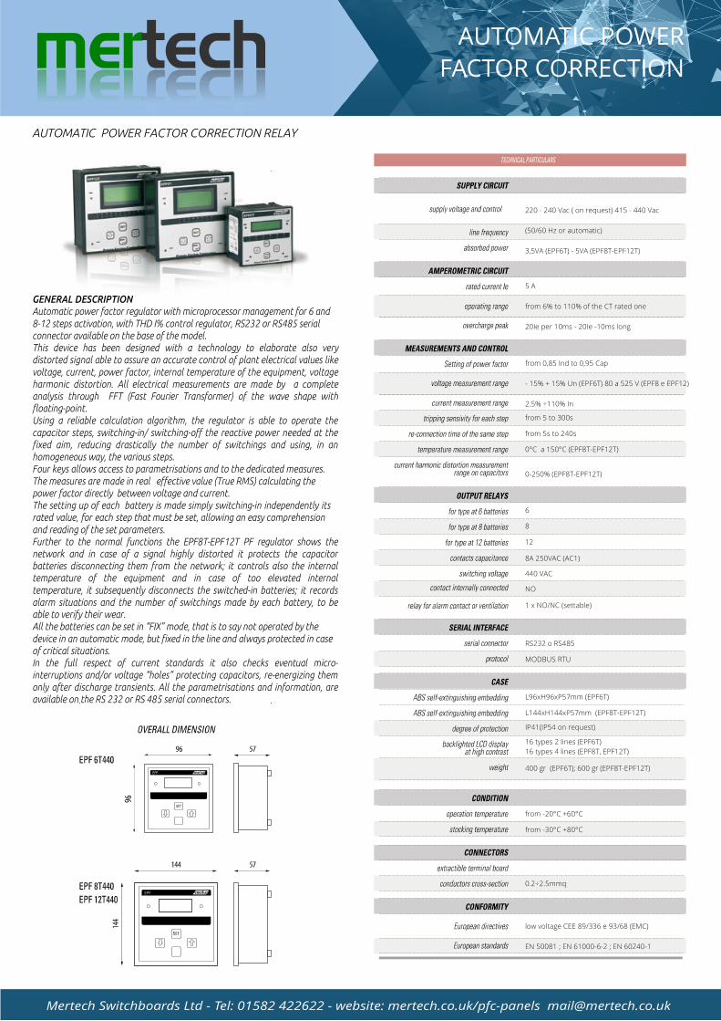
GENERAL DESCRIPTION
Automatic power factor regulator with microprocessor management for 6 and 8-12 steps activation, with THD I% control regulator, RS232 or RS485 serial connector available on the base of the model.This device has been designed with a technology to elaborate also very distorted signal able to assure an accurate control of plant electrical values like voltage, current, power factor, internal temperature of the equipment, voltage harmonic distortion. All electrical measurements are made by a complete analysis through FFT (Fast Fourier Transformer) of the wave shape with floating-point.Using a reliable calculation algorithm, the regulator is able to operate the capacitor steps, switching-in/ switching-off the reactive power needed at the fixed aim, reducing drastically the number of switchings and using, in an homogeneous way, the various steps.Four keys allows access to parametrisations and to the dedicated measures. The measures are made in real effective value (True RMS) calculating the power factor directly between voltage and current.The setting up of each battery is made simply switching-in independently its rated value, for each step that must be set, allowing an easy comprehension and reading of the set parameters.Further to the normal functions the EPF8T-EPF12T PF regulator shows the network and in case of a signal highly distorted it protects the capacitor batteries disconnecting them from the network; it controls also the internal temperature of the equipment and in case of too elevated internal temperature, it subsequently disconnects the switched-in batteries; it records alarm situations and the number of switchings made by each battery, to be able to verify their wear.All the batteries can be set in FIX mode, that is to say not operated by the device in an automatic mode, but fixed in the line and always protected in case of critical situations.In the full respect of current standards it also checks eventual micro-interruptions and/or voltage holes protecting capacitors, re-energizing them only after discharge transients. All the parametrisations and information, are available on the RS 232 or RS 485 serial connectors.
AUTOMATIC POWER
FACTOR CORRECTIONmertech
Mertech Switchboards Ltd - Tel: 01582 422622 - website: mertech.co.uk/pfc-panels [email protected]
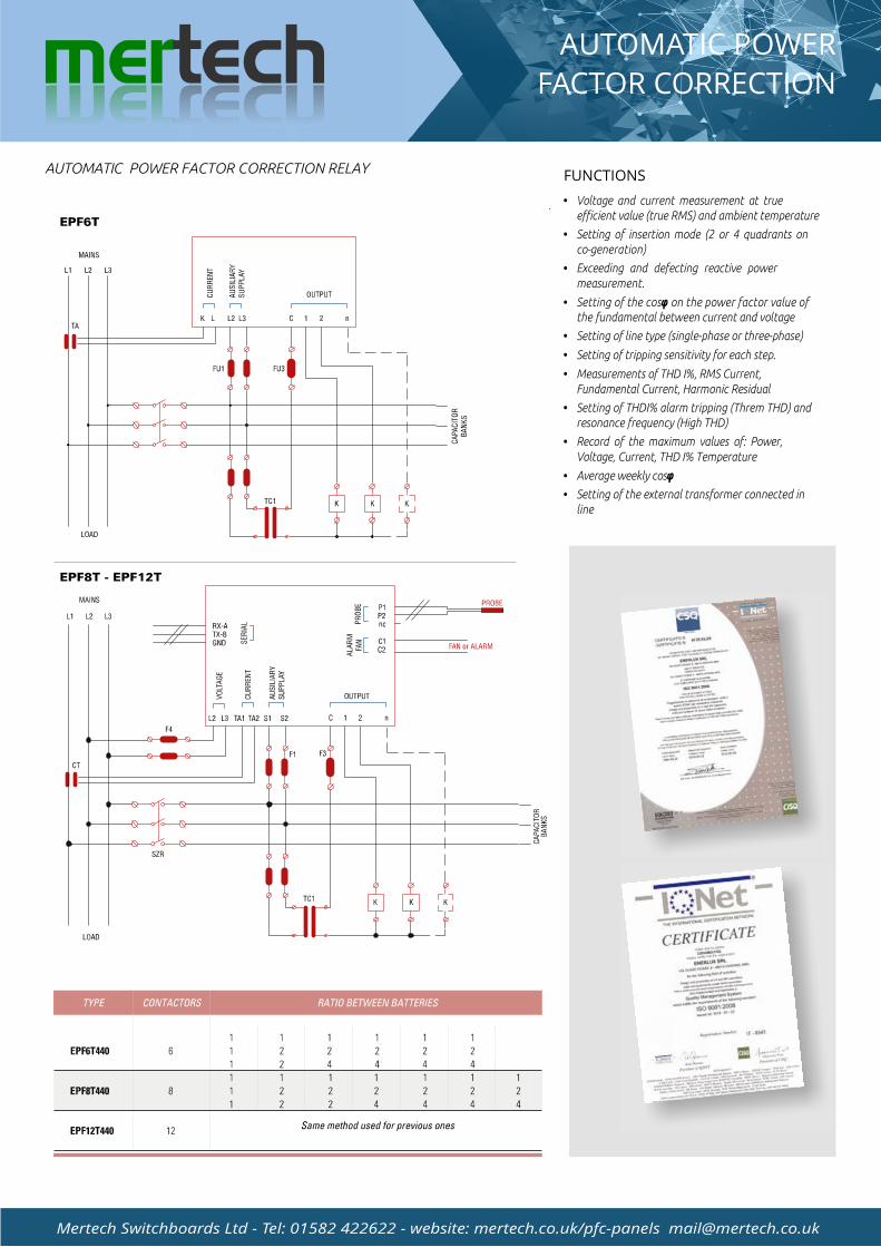
AUTOMATIC POWER FACTOR CORRECTION RELAY
220 - 240 Vac ( on request) 415 - 440 Vac
(50/60 Hz or automatic)
3,5VA (EPF6T) - 5VA (EPF8T-EPF12T)
5 A
from 6% to 110% of the CT rated one
20Ie per 10ms - 20Ie -10ms long
from 0,85 Ind to 0,95 Cap
- 15% + 15% Un (EPF6T) 80 a 525 V (EPF8 e EPF12)
2.5% ÷110% In
from 5 to 300s
from 5s to 240s
0°C a 150°C (EPF8T-EPF12T)
0-250% (EPF8T-EPF12T)
6
8
12
8A 250VAC (AC1)
440 VAC
NO
1 x NO/NC (settable)
RS232 o RS485
MODBUS RTU
L96xH96xP57mm (EPF6T)
L144xH144xP57mm (EPF8T-EPF12T)
IP41(IP54 on request)
16 types 2 lines (EPF6T)
16 types 4 lines (EPF8T, EPF12T)
400 gr (EPF6T); 600 gr (EPF8T-EPF12T)
from -20°C +60°C
from -30°C +80°C
0.2÷2.5mmq
low voltage CEE 89/336 e 93/68 (EMC)
EN 50081 ; EN 61000-6-2 ; EN 60240-1
REGULATORS EPF6T-EPF8T-EPF12T
Voltage and current measurement at true efficient value (true RMS) and ambient temperature
Setting of insertion mode (2 or 4 quadrants on co-generation)
Exceeding and defecting reactive power
measurement.
Setting of the cos on the power factor value of the fundamental between current and voltage
Setting of line type (single-phase or three-phase)
Setting of tripping sensitivity for each step.
Measurements of THD I%, RMS Current, Fundamental Current, Harmonic Residual
Setting of THDI% alarm tripping (Threm THD) and resonance frequency (High THD)
Record of the maximum values of: Power,
Voltage, Current, THD I% Temperature
Average weekly cos
Setting of the external transformer connected in line
AUTOMATIC POWER
FACTOR CORRECTIONmertech
Mertech Switchboards Ltd - Tel: 01582 422622 - website: mertech.co.uk/pfc-panels [email protected]
AUTOMATIC POWER FACTOR CORRECTION RELAYFUNCTIONS