Embed Size (px)
Citation preview
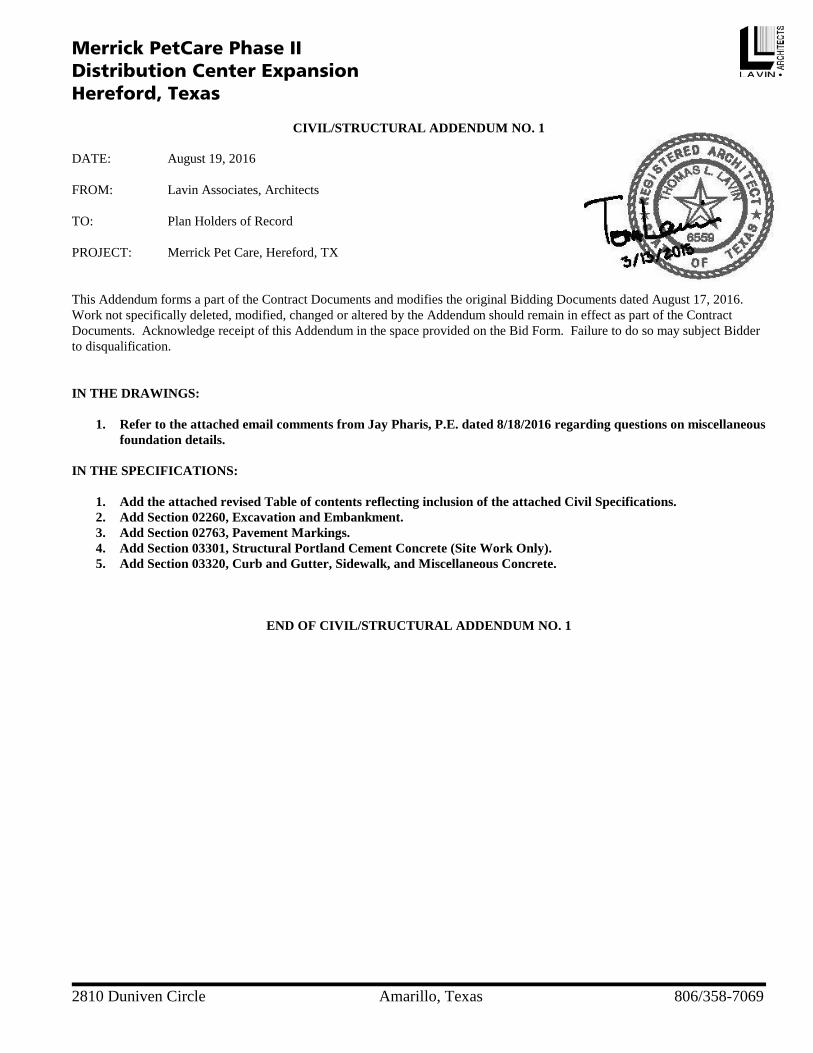
2810 Duniven Circle Amarillo, Texas 806/358-7069
Merrick PetCare Phase II Distribution Center Expansion Hereford, Texas
CIVIL/STRUCTURAL ADDENDUM NO. 1
DATE: August 19, 2016 FROM: Lavin Associates, Architects TO: Plan Holders of Record PROJECT: Merrick Pet Care, Hereford, TX This Addendum forms a part of the Contract Documents and modifies the original Bidding Documents dated August 17, 2016. Work not specifically deleted, modified, changed or altered by the Addendum should remain in effect as part of the Contract Documents. Acknowledge receipt of this Addendum in the space provided on the Bid Form. Failure to do so may subject Bidder to disqualification. IN THE DRAWINGS:
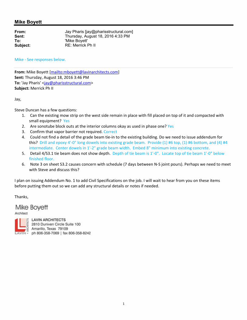
1. Refer to the attached email comments from Jay Pharis, P.E. dated 8/18/2016 regarding questions on miscellaneous foundation details.
IN THE SPECIFICATIONS:
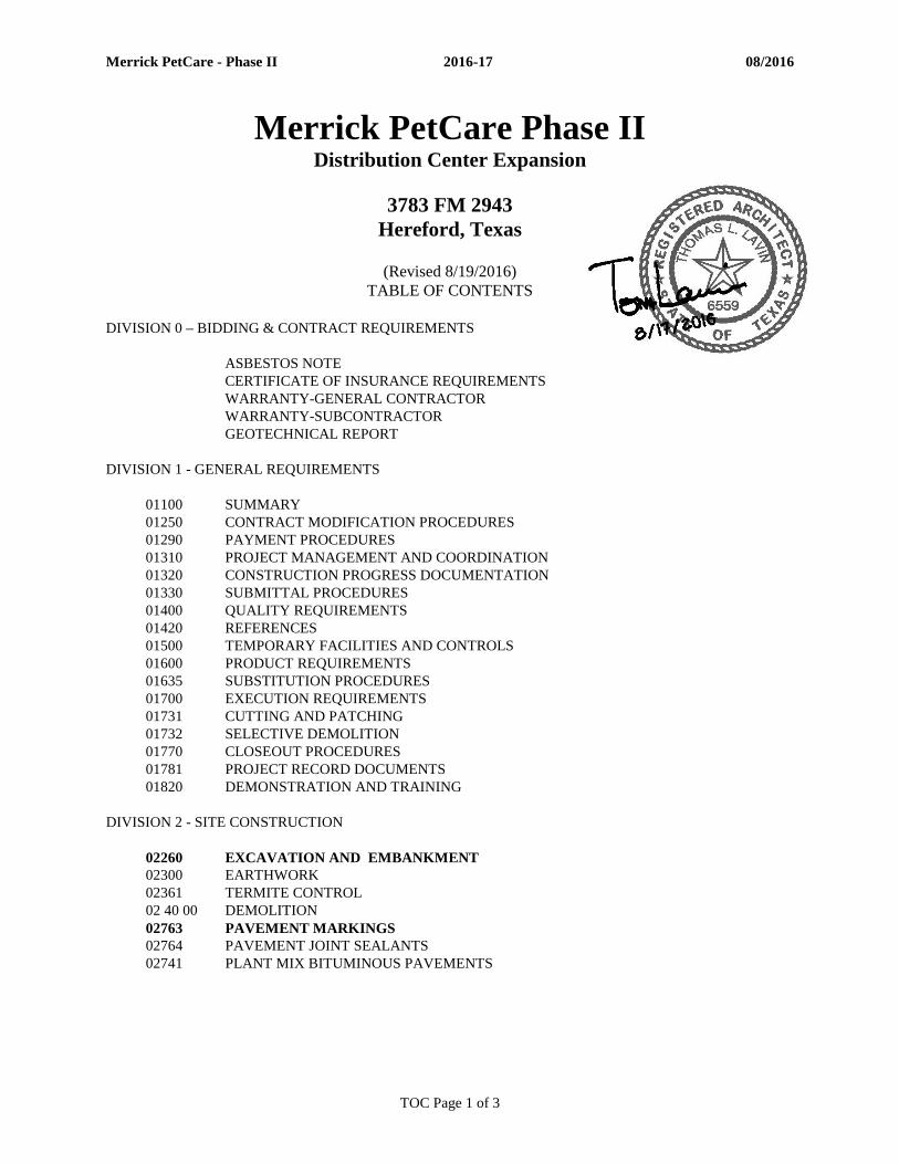
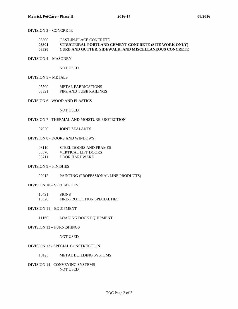
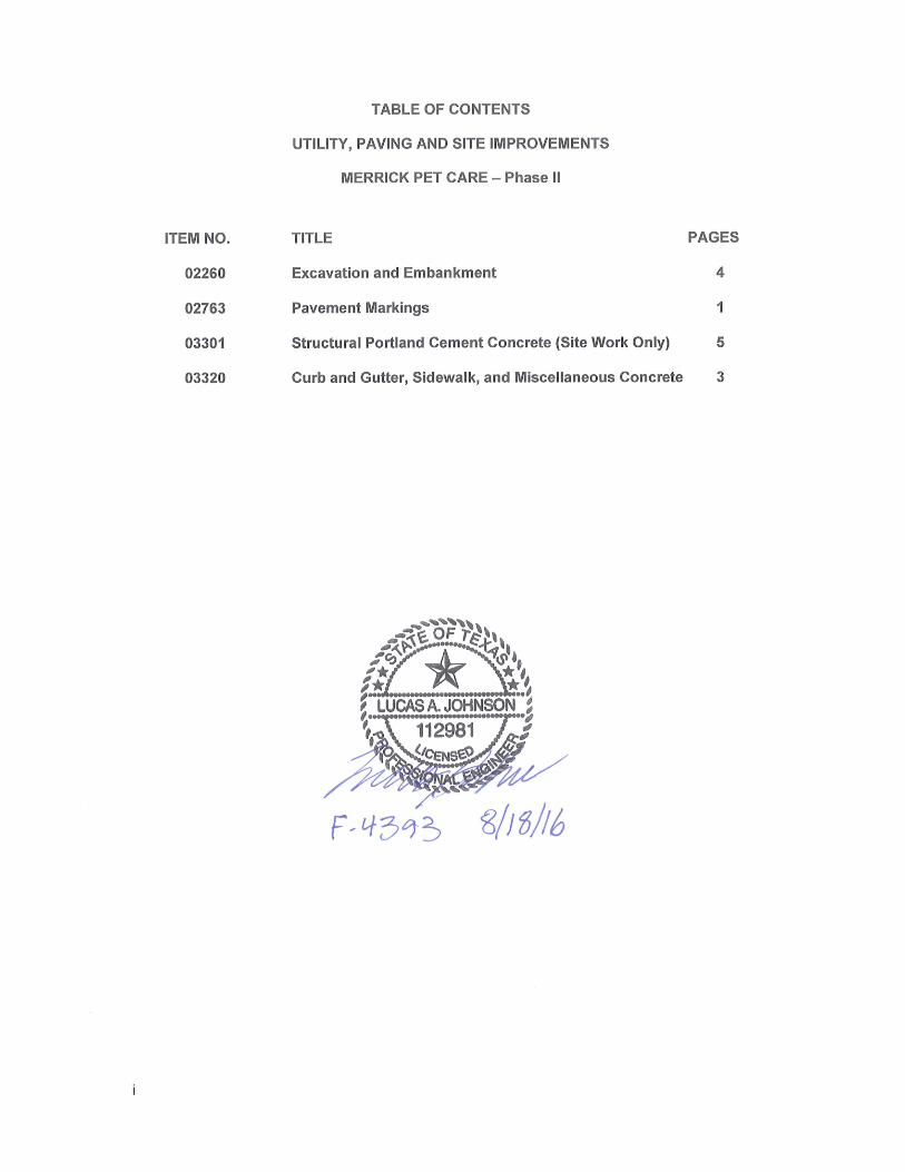
1. Add the attached revised Table of contents reflecting inclusion of the attached Civil Specifications. 2. Add Section 02260, Excavation and Embankment. 3. Add Section 02763, Pavement Markings. 4. Add Section 03301, Structural Portland Cement Concrete (Site Work Only). 5. Add Section 03320, Curb and Gutter, Sidewalk, and Miscellaneous Concrete.
END OF CIVIL/STRUCTURAL ADDENDUM NO. 1
1
Mike Boyett
From: Jay Pharis [[email protected]]Sent: Thursday, August 18, 2016 4:33 PMTo: 'Mike Boyett'Subject: RE: Merrick Ph II
Mike ‐ See responses below.
From: Mike Boyett [mailto:[email protected]] Sent: Thursday, August 18, 2016 3:46 PM To: 'Jay Pharis' <[email protected]> Subject: Merrick Ph II Jay, Steve Duncan has a few questions:
1. Can the existing mow strip on the west side remain in place with fill placed on top of it and compacted with small equipment? Yes
2. Are sonotube block outs at the interior columns okay as used in phase one? Yes 3. Confirm that vapor barrier not required. Correct 4. Could not find a detail of the grade beam tie‐in to the existing building. Do we need to issue addendum for
this? Drill and epoxy 4'‐0" long dowels into existing grade beam. Provide (1) #6 top, (1) #6 bottom, and (4) #4 intermediate. Center dowels in 1'‐2" grade beam width. Embed 8" minimum into existing concrete.
5. Detail 4/S3.1 tie beam does not show depth. Depth of tie beam is 1'‐0". Locate top of tie beam 1'‐0" below finished floor.
6. Note 3 on sheet S3.2 causes concern with schedule (7 days between N‐S joint pours). Perhaps we need to meet with Steve and discuss this?
I plan on issuing Addendum No. 1 to add Civil Specifications on the job. I will wait to hear from you on these items before putting them out so we can add any structural details or notes if needed. Thanks,
Merrick PetCare - Phase II 2016-17 08/2016
TOC Page 1 of 3
Merrick PetCare Phase II Distribution Center Expansion
3783 FM 2943
Hereford, Texas
(Revised 8/19/2016) TABLE OF CONTENTS
DIVISION 0 – BIDDING & CONTRACT REQUIREMENTS ASBESTOS NOTE CERTIFICATE OF INSURANCE REQUIREMENTS WARRANTY-GENERAL CONTRACTOR WARRANTY-SUBCONTRACTOR GEOTECHNICAL REPORT DIVISION 1 - GENERAL REQUIREMENTS 01100 SUMMARY 01250 CONTRACT MODIFICATION PROCEDURES 01290 PAYMENT PROCEDURES 01310 PROJECT MANAGEMENT AND COORDINATION 01320 CONSTRUCTION PROGRESS DOCUMENTATION 01330 SUBMITTAL PROCEDURES 01400 QUALITY REQUIREMENTS 01420 REFERENCES 01500 TEMPORARY FACILITIES AND CONTROLS 01600 PRODUCT REQUIREMENTS 01635 SUBSTITUTION PROCEDURES 01700 EXECUTION REQUIREMENTS 01731 CUTTING AND PATCHING 01732 SELECTIVE DEMOLITION 01770 CLOSEOUT PROCEDURES 01781 PROJECT RECORD DOCUMENTS 01820 DEMONSTRATION AND TRAINING DIVISION 2 - SITE CONSTRUCTION 02260 EXCAVATION AND EMBANKMENT 02300 EARTHWORK 02361 TERMITE CONTROL 02 40 00 DEMOLITION 02763 PAVEMENT MARKINGS 02764 PAVEMENT JOINT SEALANTS 02741 PLANT MIX BITUMINOUS PAVEMENTS
Merrick PetCare - Phase II 2016-17 08/2016
TOC Page 2 of 3
DIVISION 3 – CONCRETE 03300 CAST-IN-PLACE CONCRETE 03301 STRUCTURAL PORTLAND CEMENT CONCRETE (SITE WORK ONLY) 03320 CURB AND GUTTER, SIDEWALK, AND MISCELLANEOUS CONCRETE DIVISION 4 – MASONRY NOT USED DIVISION 5 – METALS 05500 METAL FABRICATIONS 05521 PIPE AND TUBE RAILINGS DIVISION 6 - WOOD AND PLASTICS NOT USED DIVISION 7 - THERMAL AND MOISTURE PROTECTION 07920 JOINT SEALANTS DIVISION 8 - DOORS AND WINDOWS 08110 STEEL DOORS AND FRAMES 08370 VERTICAL LIFT DOORS 08711 DOOR HARDWARE DIVISION 9 – FINISHES 09912 PAINTING (PROFESSIONAL LINE PRODUCTS) DIVISION 10 – SPECIALTIES 10431 SIGNS 10520 FIRE-PROTECTION SPECIALTIES DIVISION 11 – EQUIPMENT 11160 LOADING DOCK EQUIPMENT DIVISION 12 – FURNISHINGS NOT USED DIVISION 13 - SPECIAL CONSTRUCTION
13125 METAL BUILDING SYSTEMS DIVISION 14 - CONVEYING SYSTEMS NOT USED

Merrick PetCare - Phase II 2016-17 08/2016
TOC Page 3 of 3
DIVISION 21 – FIRE SUPPRESSION 21 05 17 SLEEVES AND SLEEVE SEALS FOR FIRE-SUPPRESSION PIPING 21 05 18 ESCUTCHEONS FOR FIRE-SUPPRESSION PIPING 21 13 13 WET-PIPE SPRINKLER SYSTEMS DIVISION 22 – PLUMBING 22 05 29 HANGERS AND SUPPORTS FOR PLUMBING PIPING AND EQUIPMENT 22 05 53 IDENTIFICATION FOR PLUMBING PIPING AND EQUIPMENT 22 07 19 PLUMBING PIPING INSULATION 22 11 16 DOMESTIC WATER PIPING 22 11 19 DOMESTIC WATER PIPING SPECIALTIES 22 11 23 FACILITY NATURAL-GAS PIPING 22 13 16 SANITARY WASTE AND VENT PIPING 22 15 13 GENERAL-SERVICE COMPRESSED-AIR PIPING DIVISION 23 - HEATING VENTILATING AND AIR CONDITIONING 23 05 13 COMMON MOTOR REQUIREMENTS FOR HVAC EQUIPMENT 23 05 29 HANGERS AND SUPPORTS FOR HVAC EQUIPMENT 23 05 53 IDENTIFICATION FOR HVAC EQUIPMENT AND DUCT 23 05 93 TESTING, ADJUSTING, AND BALANCING FOR HVAC 23 34 23 HVAC POWER VENTILATORS 23 55 33.16 GAS-FIRED UNIT HEATERS
DIVISION 26 – ELECTRICAL 26 05 19 LOW-VOLTAGE FOR ELECTRICAL POWER CONDUCTORS AND CABLES 26 05 26 GROUNDING AND BONDING FOR ELECTRICAL SYSTEMS 26 05 29 HANGERS AND SUPPORTS FOR ELECTRICAL SYSTEMS 26 05 33 RACEWAYS AND BOXES FOR ELECTRICAL SYSTEMS 26 05 44 SLEEVES AND SLEEVE SEALS FOR ELECTRICAL 26 05 53 IDENTIFICATION FOR ELECTRICAL SYSTEMS 26 05 73 OVERCURRENT PROTECTIVE DEVICE COORDINATION STUDY 26 09 23 LIGHTING CONTROL DEVICES 26 24 16 PANELBOARDS 26 27 26 WIRING DEVICES 26 28 16 ENCLOSED SWITCHES AND CIRCUIT BREAKERS 26 51 19 INTERIOR LIGHTING 26 56 00 EXTERIOR LIGHTING DIVISION 28 – FIRE ALARM
28 31 11 DIGITAL, ADDRESSABLE FIRE-ALARM SYSTEM
END OF TABLE OF CONTENTS
Merrick Pet Care – Phase II 2016-17 08/2016
EXCAVATION AND EMBANKMENT 02260 - 1
SECTION 02260 - EXCAVATION AND EMBANKMENT
PART 1: GENERAL
1.1 This item covers excavation, disposal, placement, and compaction of all materials within the lim-its of the work required to construct streets and parking areas as well as other areas for drainage, sidewalks or other purposes in accordance with these specifications and in conformity to the di-mensions and typical section shown on the plans. Building pad construction is not a part of this section of specifications. When this specification conflicts with the Geotechnical Soils Investiga-tion, the recommendations in the Geotechnical soils investigation shall followed in place of these specifications. A copy of the Geotechnical Soils Investigation, if not available with the official bid documents, will be made available upon request. Additionally, where plan sheets conflict with specifications, the plans sheets shall be used in place of specifications.
1.2 CLASSIFICATION. All material excavated shall be classified as defined below:
(a) Unclassified Excavation. Unclassified excavation shall consist of the excavation and dis-posal of all material, regardless of its nature.
1.3 UNSUITABLE EXCAVATION. Any material containing vegetable or organic matter, such as
muck, peat, organic silt, or sod shall be considered unsuitable for use in embankment construc-tion.
PART 2: EXECUTION
2.1 GENERAL. All unsuitable material shall be disposed of off-site.
If necessary to interrupt existing surface drainage, sewers or under-drainage, conduits, utilities, or similar underground structures the Contractor shall be responsible for and shall take all necessary precautions to preserve them or provide temporary services. The Contractor shall, at his own ex-pense, satisfactorily repair or pay the cost of all damage to such facilities or structures, which may result from any of the Contractor’s operations during the period of the contract.
2.2 EXCAVATION. No excavation shall be started until the Contractor has staked out the work.
All suitable excavated material shall be used in the formation of embankment, subgrade, or for other purposes shown on the plans. All unsuitable material shall be disposed of off-site.
When the volume of the excavation exceeds that required to construct the embankments to the grades indi-cated, the excess shall be used to grade the areas of ultimate development or disposed of as directed. When the volume of excavation is not sufficient for constructing the fill to the grades indicated, the deficiency shall be obtained from approved sources. The grade shall be maintained so that the surface is well drained at all times. When necessary, temporary drains and drainage ditches shall be installed to intercept or divert surface water, which may affect the work. (a) Removal of Utilities. The removal of existing structures and utilities required to permit
the orderly progress of work will be accomplished by someone other than the Contractor, e.g., the utility unless otherwise shown on the plans. All existing foundations shall be excavated for at least 2 feet below the top of subgrade or as indicated on the plans, and

Merrick Pet Care – Phase II 2016-17 08/2016
EXCAVATION AND EMBANKMENT 02260 - 2
the material disposed of as directed. All foundations thus excavated shall be backfilled with suitable material and compacted as specified herein.
(b) Compaction Requirements. The subgrade under areas to be paved shall be compacted to a depth as shown on the plans and made sure to comply with the geotechnical soils in-vestigation. Compaction shall be to a density of not less than 95 percent for cohesive soils or 100 percent for noncohesive soils of the maximum density as determined by ASTM D 698. One dry density and moisture content test per 300 hundred (300) square yards.
The in-place field density shall be determined in accordance with ASTM D1556, ASTM D 2167 or ASTM 2922. Stones or rock fragments larger than 4 inches in their greatest dimension will not be permitted in top 6 inches of the subgrade. The finished grading operations, conforming to the typical cross section, shall be completed and maintained at least 1,000 feet ahead of the paving operations or as directed by the Engineer. All cut-and-fill slopes shall be uniformly dressed to the slope, cross section, and align-ment shown on the plans or as directed by the Engineer.
2.3 DRAINAGE EXCAVATION. Drainage excavation shall consist of excavating for drainage
ditches such as intercepting, inlet or outlet, for temporary levee construction; or for any other type as designed or as shown on the plans. The work shall be performed in the proper sequence with the other construction. All satisfactory material shall be placed in fills; unsuitable material shall be placed in waste areas or as directed. Intercepting ditches shall be constructed prior to starting adjacent excavation operations. All necessary work shall be performed to secure a finish true to line, elevation, and cross section.
The Contractor shall maintain ditches constructed on the project to the required cross section and shall keep them free of debris or obstructions until the project is accepted.
2.4 PREPARATION OF EMBANKMENT AREA. Where an embankment is to be constructed to
a height of 4 feet or less, all sod and vegetable matter shall be removed from the surface upon which the embankment is to be placed, and the cleared surface shall be completely broken up by plowing or scarifying to a minimum depth of 6 inches. This area shall then be compacted as indi-cated in paragraph 2.5.
2.5 FORMATION OF EMBANKMENTS. Embankments shall be formed in successive horizontal
layers of not more than 8 inches in loose depth for the full width of the cross section, unless oth-erwise approved by the Engineer.
The grading operations shall be conducted, and the various soil strata shall be placed, to produce a soil structure as shown on the typical cross section or as directed. Materials such as brush, hedge, roots, stumps, grass and other organic matter, shall not be incorporated or buried in the embankment. Operations on earthwork shall be suspended at any time when satisfactory results cannot be ob-tained because of rain, freezing, or other unsatisfactory conditions of the field. The Contractor shall drag, blade, or slope the embankment to provide proper surface drainage. The material in the layer shall be within +/-2 percent of optimum moisture content before rolling to obtain the prescribed compaction. In order to achieve a uniform moisture content throughout the layer, wetting or drying of the material and manipulation shall be required when necessary.
Merrick Pet Care – Phase II 2016-17 08/2016
EXCAVATION AND EMBANKMENT 02260 - 3
Should the material be too wet to permit proper compaction or rolling, all work on all of the af-fected portions of the embankment shall be delayed until the material has dried to the required moisture content. Sprinkling of dry material to obtain the proper moisture content shall be done with approved equipment that will sufficiently distribute the water. Sufficient equipment to fur-nish the required water shall be available at all times. Rolling operations shall be continued until the embankment is compacted to not less that 95 per-cent of maximum density for noncohesive and cohesive soils as determined by ASTM D 698. Under all areas to be paved, the embankments shall be compacted to a depth of 6 inches and to a density of not less that 95 percent of the maximum density as determined by ASTM D 698. One dry density and moisture content test per three hundred (300) square yards. On all areas outside of the pavement areas, no compaction will be required on the top 4 inches. The in-place field density shall be determined in accordance with ASTM D 1556, ASTM D 2167 or ASTM D 2922. Compaction areas shall be kept separate, and no layer shall be covered by another until the proper density is obtained. During construction of the embankment, the Contractor shall route equipment at all times, both when loaded and when empty, over the layers as they are placed and shall distribute the travel evenly over the entire width of the embankment. The equipment shall be operated in such a man-ner that hardpan, cemented gravel, clay, or other chunky soil material will be broken up into small particles and become incorporated with the other material in the layer. In the construction of embankments, layer placement shall begin in the deepest portion of the fill; as placement progresses, layers shall be constructed approximately parallel to the finished pave-ment grade line. When rock and other embankment material are excavated at approximately the same time, the rock shall be incorporated into the outer portion of the embankment and the other material shall be incorporated under the future paved areas. Stones or fragmentary rock larger than 4 inches in their greatest dimensions will be not be allowed in the top 6 inches of the subgrade. Rockfill shall be brought up in layers as specified or as directed and every effort shall be exerted to fill the voids with the finer material forming a dense, compact mass. Rock or boulders shall not be dis-posed of outside the excavation or embankment areas, except at places and in the manner desig-nated. When the excavated material consists predominantly of rock fragments of such size that the mate-rial cannot be placed in layers of the prescribed thickness without crushing, pulverizing or further breaking down the pieces, such material may be placed in the embankment as directed in layers not exceeding 2 feet in thickness. Each layer shall be leveled and smoothed with suitable leveling equipment and by distribution of spalls and finer fragments of rock. These type lifts shall not be constructed above an elevation 4 feet below the finished subgrade. Density requirements will not apply to portions of embankments constructed of materials, which cannot be tested in accordance with specified methods. Frozen material shall not be placed in the embankment nor shall embankment be placed upon fro-zen material.
Merrick Pet Care – Phase II 2016-17 08/2016
EXCAVATION AND EMBANKMENT 02260 - 4
2.6 FINISHING AND PROTECTION OF SUBGRADE. After the subgrade has been substantial-ly completed the full width shall be conditioned by removing any soft or other unstable material which will not compact properly. The resulting areas and all other low areas, holes or depres-sions shall be brought to grade with suitable select material. Scarifying, blading, rolling and other methods shall be performed to provide a thoroughly compacted subgrade shaped to the lines and grades shown on the plans.
Grading of the subgrade shall be performed so that it will drain readily. The Contractor shall take all pre-cautions necessary to protect the subgrade from damage and shall limit hauling over the finished subgrade to that which is essential for construction purposes. All ruts or rough places that develop in a completed subgrade shall be smoothed and recompacted.
2.7 HAUL. All hauling will be considered a necessary and incidental part of the work. Its cost shall
be considered by the Contractor and included in the contract price for the pay of items of work involved. No payment will be made separately or directly for hauling on any part of the work.
2.8 TOLERANCES. In those areas upon which a base course is to be placed, the top of the sub-
grade shall be of such smoothness that, when tested with a 16-foot straightedge applied parallel and at right angles to the centerline, it shall not show any deviation in excess of ½ inch, or shall not be more than 0.04 foot from true grade as established by grade hubs or pins. Any deviation in excess of these amounts shall be corrected by loosening, adding, or removing materials; reshap-ing; and recompacting by sprinkling and rolling.
On shoulder areas, intermediate and other designated areas, the surface shall be of such smoothness that it will not vary more than 0.10 foot from true grade as established by grade hubs. Loosening, adding or re-moving materials, and reshaping shall correct any deviation in excess of this amount.
END OF SECTION 02260
Merrick Pet Care – Phase II 2016-17 08/2016
PAVEMENT MARKINGS 02763 - 1
SECTION 02763 – PAVEMENT MARKINGS PART 1: GENERAL 1.1 GENERAL. This Section includes the following: Furnish and install all painted lines, directional ar-
rows, handicapped symbols, or similar markings on paved surfaces, as shown on the drawings or speci-fied herein, as required by jurisdiction having authority, and as required to complete the work.
PART 2: PRODUCTS 2.1 TRAFFIC MARKING PAINT. Acrylic Waterborne Paint or Low Volatile Organic Compound (VOC)
solvent base paint, lead and chromate free, ready-mixed, cold applied traffic marking paint, white or yellow color as designated on the plans for striping and lane markings, white and blue as international handicapped parking symbols. Acceptable products include Devoe Exterior “Safety Line” or approved equal.
PART 3: EXECUTION 3.1 EXAMINATION
A. Verification of Conditions: Examine areas and conditions under which the work of this Section will be performed. Do not proceed with the work until unsatisfactory conditions have been corrected. Com-mencement of work implies acceptance of all areas and conditions.
3.2 PREPARATION
A. Surface Preparation: Allow fresh pavement surfaces to weather at least 30 days prior to appli-cation of traffic marking paint.
3.3 APPLICATION
A. Traffic Marking Paint: Unless otherwise indicated, apply traffic marking paint in nominal 4” wide stripes at the rate of 100 to 110 sf/gal 1. Unless otherwise indicated, apply traffic markings in nominal 4” wide stripes with clear and
sharp dimensions. See drawings for striping patterns, directional arrows and symbols. 2. Unless otherwise indicated, use yellow markings at lane striping and directional
symbols, white markings at parking striping and white and blue markings at in-ternational handicapped symbols.
3. Comply with ANSI 117.1 and ADA requirements for graphic symbols, stall widths, and access aisles at handicapped parking spaces. Provide approved templates for symbols and directional arrows.
END OF SECTION 02763
Merrick Pet Care – Phase II 2016-17 08/2016
STRUCTURAL PORTLAND CEMENT CONCRETE 03301 - 1
SECTION 03301 - STRUCTURAL PORTLAND CEMENT CONCRETE (SITE WORK ONLY)
PART 1: GENERAL 1.1 This item shall consist of reinforced structural portland cement concrete, prepared and constructed in ac-
cordance with these specifications, at the locations and of the form and dimensions shown on the plans. PART 2: MATERIALS 2.1 GENERAL. Only approved materials, conforming to the requirements of these specifications shall be
used in the work. They may be subjected to inspection and tests at any time during the progress of their preparation or use. Test certificates for each of the materials shall be submitted by the Contractor for ap-proval. Materials shall be stored and handled to insure the preservation of their quality and fitness for use and shall be located to facilitate prompt inspection. All equipment for handling and transporting materials and concrete must be clean before any material or concrete is placed therein.
In no case shall the use of pit-run or naturally mixed aggregated be permitted. Naturally mixed aggregate shall be screened and washed, and all fine and coarse aggregates shall be stored separately and kept clean. The mixing of different kinds of aggregates from different sources in one storage pile or alternating batches of different aggregates will not be permitted.
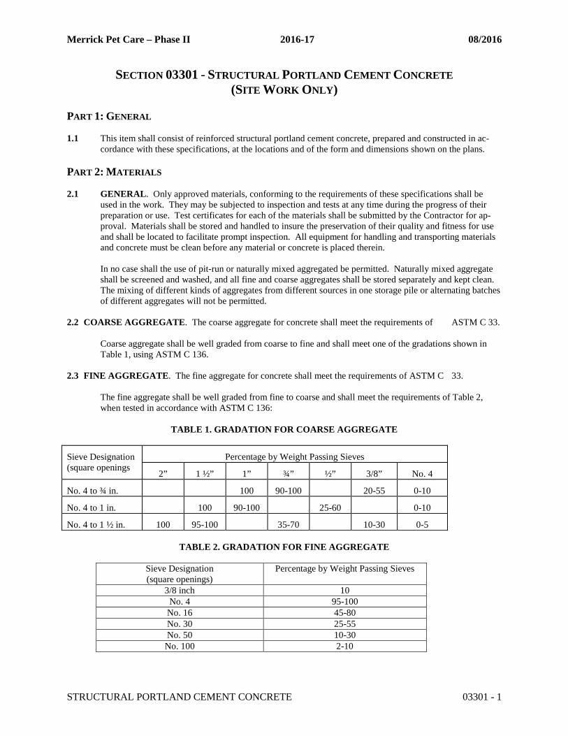
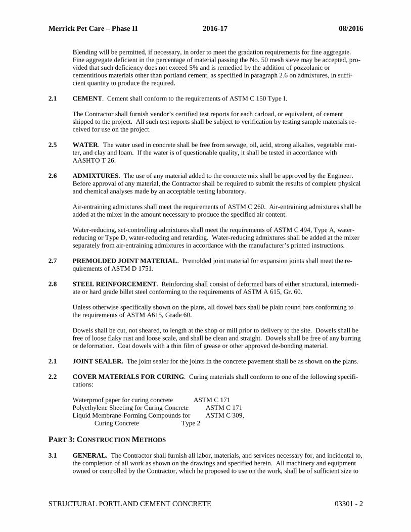
2.2 COARSE AGGREGATE. The coarse aggregate for concrete shall meet the requirements of ASTM C 33.
Coarse aggregate shall be well graded from coarse to fine and shall meet one of the gradations shown in Table 1, using ASTM C 136.
2.3 FINE AGGREGATE. The fine aggregate for concrete shall meet the requirements of ASTM C 33.
The fine aggregate shall be well graded from fine to coarse and shall meet the requirements of Table 2, when tested in accordance with ASTM C 136:
TABLE 1. GRADATION FOR COARSE AGGREGATE
Sieve Designation (square openings
Percentage by Weight Passing Sieves
2” 1 ½” 1” ¾” ½” 3/8” No. 4
No. 4 to ¾ in. 100 90-100 20-55 0-10
No. 4 to 1 in. 100 90-100 25-60 0-10
No. 4 to 1 ½ in. 100 95-100 35-70 10-30 0-5
TABLE 2. GRADATION FOR FINE AGGREGATE
Sieve Designation (square openings)
Percentage by Weight Passing Sieves
3/8 inch 10 No. 4 95-100
No. 16 45-80 No. 30 25-55 No. 50 10-30
No. 100 2-10
Merrick Pet Care – Phase II 2016-17 08/2016
STRUCTURAL PORTLAND CEMENT CONCRETE 03301 - 2
Blending will be permitted, if necessary, in order to meet the gradation requirements for fine aggregate. Fine aggregate deficient in the percentage of material passing the No. 50 mesh sieve may be accepted, pro-vided that such deficiency does not exceed 5% and is remedied by the addition of pozzolanic or cementitious materials other than portland cement, as specified in paragraph 2.6 on admixtures, in suffi-cient quantity to produce the required.
2.1 CEMENT. Cement shall conform to the requirements of ASTM C 150 Type I.
The Contractor shall furnish vendor’s certified test reports for each carload, or equivalent, of cement shipped to the project. All such test reports shall be subject to verification by testing sample materials re-ceived for use on the project.
2.5 WATER. The water used in concrete shall be free from sewage, oil, acid, strong alkalies, vegetable mat-
ter, and clay and loam. If the water is of questionable quality, it shall be tested in accordance with AASHTO T 26.
2.6 ADMIXTURES. The use of any material added to the concrete mix shall be approved by the Engineer.
Before approval of any material, the Contractor shall be required to submit the results of complete physical and chemical analyses made by an acceptable testing laboratory.
Air-entraining admixtures shall meet the requirements of ASTM C 260. Air-entraining admixtures shall be added at the mixer in the amount necessary to produce the specified air content.
Water-reducing, set-controlling admixtures shall meet the requirements of ASTM C 494, Type A, water-reducing or Type D, water-reducing and retarding. Water-reducing admixtures shall be added at the mixer separately from air-entraining admixtures in accordance with the manufacturer’s printed instructions.
2.7 PREMOLDED JOINT MATERIAL. Premolded joint material for expansion joints shall meet the re-
quirements of ASTM D 1751. 2.8 STEEL REINFORCEMENT. Reinforcing shall consist of deformed bars of either structural, intermedi-
ate or hard grade billet steel conforming to the requirements of ASTM A 615, Gr. 60. Unless otherwise specifically shown on the plans, all dowel bars shall be plain round bars conforming to the requirements of ASTM A615, Grade 60. Dowels shall be cut, not sheared, to length at the shop or mill prior to delivery to the site. Dowels shall be free of loose flaky rust and loose scale, and shall be clean and straight. Dowels shall be free of any burring or deformation. Coat dowels with a thin film of grease or other approved de-bonding material.
2.1 JOINT SEALER. The joint sealer for the joints in the concrete pavement shall be as shown on the plans.
2.2 COVER MATERIALS FOR CURING. Curing materials shall conform to one of the following specifi-
cations:
Waterproof paper for curing concrete ASTM C 171 Polyethylene Sheeting for Curing Concrete ASTM C 171 Liquid Membrane-Forming Compounds for ASTM C 309, Curing Concrete Type 2
PART 3: CONSTRUCTION METHODS
3.1 GENERAL. The Contractor shall furnish all labor, materials, and services necessary for, and incidental to, the completion of all work as shown on the drawings and specified herein. All machinery and equipment owned or controlled by the Contractor, which he proposed to use on the work, shall be of sufficient size to
Merrick Pet Care – Phase II 2016-17 08/2016
STRUCTURAL PORTLAND CEMENT CONCRETE 03301 - 3
meet the requirements of the work, and shall be such as to produce satisfactory work. All work shall be subject to the inspection by the Engineer.
3.2 CONCRETE COMPOSITION. The concrete shall develop a compressive strength of 4,000 psi in 28
days as determined by test cylinders made in accordance with ASTM C 31 and tested in accordance with ASTM C 39. The concrete shall contain not less than 611 pounds (6.5 sacks) of cement per cubic yard. The concrete shall contain 5 percent of entrained air, plus or minus 1 percent, as determined by ASTM C 231 and shall have a slump of not more than 4 inches as determined by ASTM C 143. Collated, fibrillated polypropylene fiber shall be added at the rate of 1.5 pounds per cubic yard.
3.3 ACCEPTANCE SAMPLING AND TESTING. Concrete for each structure will be accepted on the basis
of the compressive strength specified in paragraph 3.2. The concrete shall be sampled in accordance with ASTM C 172. Compressive strength specimens shall be made in accordance with ASTM C 31 and tested in accordance with ASTM C 39.
Concrete cylindrical test specimens shall be made in accordance with ASTM C 31 and tested in accordance with ASTM C 39. The Contractor shall cure and store the test specimens under such conditions as directed. The contractor will make the actual tests on the specimens.
The group of test for quality and a mix design shall be made prior to delivery to the project site by the Con-tractor. The quality testing and mix design shall be furnished and paid for by the Contractor. If less than year old test results and a mix design are available, these dated test results may be accepted in lieu of addi-tional testing. If during the project, the asphaltic concrete changes, the Contractor, at his expense, shall provide new quality test results and mix design.
Each transit truck load shall have a slump and air content test performed by the contractor. The first truck of each day and every 50 cubic yards after shall have a Seven (7), Fourteen (14) and twenty-
eight (28) compressive strengths.
3.4 PROPORTIONING AND MEASURING DEVICES. When package cement is used, the quantity for
each batch shall be equal to one or more whole sacks of cement. The aggregated shall be measured sepa-rately by weight. If aggregates are delivered to the mixer in batch trucks, the exact amount for each mixer charge shall be contained in each batch compartment. Weighing boxes or hoppers shall provide means of regulating the flow of aggregates into the batch box so that the required and exact weight of aggregated can be readily obtained.
3.5 CONSISTENCY. The consistency of the concrete shall be checked by the slump test specified in ASTM
C 143. 3.6 MIXING. Concrete may be mixed at the construction site, at a central point, or wholly or in part in truck
mixers. The concrete shall be mixed and delivered in accordance with the requirements of ASTM C 94. 3.7 MIXING CONDITIONS. The concrete shall be mixed only in quantities required for immediate use.
Concrete shall not be mixed while the air temperature is below 40 F without permission of the Engineer. If permission is granted for mixing under such conditions, aggregates or water, or both shall be heated and the concrete shall be placed at a temperature not less than 50 nor more than 100 F. The Contractor shall be held responsible for any defective work, resulting from freezing or injury in any manner during placing and curing, and shall replace such work at his/her expense.
Retempering of concrete by adding water or any other material shall not be permitted.
The delivery of concrete to the job shall be in such a manner that batches of concrete will be deposited at uninterrupted intervals.
Merrick Pet Care – Phase II 2016-17 08/2016
STRUCTURAL PORTLAND CEMENT CONCRETE 03301 - 4
3.8 FORMS. Forms shall be of suitable material and shall be of the type, size, shape, quality, and strength to build the structure as designed on the plans. The forms shall be true to line and grade and shall be mortar-tight and sufficiently rigid to prevent displacement and sagging between supports. The Contractor shall bear responsibility for their adequacy. The surfaces of forms shall be smooth and free from irregularities, dents, sags, and holes.
The internal ties shall be arranged so that, when the forms are removed, no metal will show in the concrete surface or discolor the surface when exposed to weathering. All forms shall be wetted with water or with a nonstaining mineral oil which shall be applied shortly before the concrete is placed. Forms shall be con-structed so that they can be removed without injuring the concrete or concrete surface. The forms shall not be removed before expiration of at least 30 hours from vertical faces, walls, slender columns, and similar structures; forms supported by falsework under slabs, beams, girders, arches, and similar construction shall not be removed until tests indicate that at least 60% of the design strength of the concrete has developed.
3.9 PLACING REINFORCEMENT. All reinforcement shall be accurately placed, as shown on the plans,
and shall be firmly held in position during concreting. Bars shall be fastened together at intersections. The reinforcement shall be supported by approved metal chairs. Shop drawings, lists, and bending details shall be supplied by the Contractor when required.
3.10 EMBEDDED ITEMS. Before placing concrete, any items that are to be embedded shall be firmly and
securely fastened in place as indicated. All such items shall be clean and free from coating, rust, scale, oil, or any foreign matter. The embedding of wood shall be avoided. The concrete shall be spaded and consol-idated around and against embedded items.
3.11 PLACING CONCRETE. All concrete shall be placed during daylight, unless otherwise approved. The
concrete shall not be placed until the depth and character of foundation, the adequacy of forms and falsework, and the placing of the steel reinforcing have been approved. Concrete shall be placed as soon as practical after mixing and in no case later than 1 hour after water has been added to the mix. The method and manner of placing shall be such to avoid segregation and displacement of the reinforcement. Troughs, pipes, and chutes shall be used as an aid in placing concrete when necessary. Dropping the concrete a dis-tance of more than 5 feet, or depositing a large quantity at one point, will not be permitted. Concrete shall be placed upon clean, damp surfaces, free from running water, or upon properly consolidated soil.
The concrete shall be compacted with suitable mechanical vibrators operating within the concrete. When necessary, vibrating shall be supplemented by hand spading with suitable tools to assure proper and ade-quate compaction. Vibrators shall be manipulated so as to work the concrete thoroughly around the rein-forcement and embedded fixtures and into corners and angles of the forms. The vibration at any joint shall be of sufficient duration to accomplish compaction but shall not be prolonged to the point where segrega-tion occurs. Concrete deposited under water shall be carefully placed in a compact mass in its final posi-tion by means of a tremie, a closed bottom dump bucket, or other approved method and shall not be dis-turbed after being deposited.
3.12 CONSTRUCTION JOINTS. When the placing of concrete is suspended, necessary provisions shall be
made for joining future work before the placed concrete take its initial set. For the proper bonding of old and new concrete, such provisions shall be made for grooves, steps, keys dovetails, reinforcing bars or oth-er devices as may be prescribed. The work shall be arranged so that a section begun on any day shall be finished during daylight of the same day. Before depositing new concrete on or against concrete which has hardened, the surface of the hardened concrete shall be cleaned by a heavy steel broom, roughened slightly, wetted, and covered with a neat coating of cement paste or grout.
3.13 EXPANSION JOINTS. Expansion joints shall be constructed at such points and of such dimensions as
may be indicated on the drawings. The premolded filler shall be cut to the same shape as that of the surfac-es being joined. The filler shall be fixed firmly against the surface of the concrete already in place in such manner that it will not be displaced when concrete is deposited against it.
Merrick Pet Care – Phase II 2016-17 08/2016
STRUCTURAL PORTLAND CEMENT CONCRETE 03301 - 5
3.14 DEFECTIVE WORK. Any defective work disclosed after the forms have been removed shall be imme-diately removed and replaced. If any dimensions are deficient, or if the surface of the concrete is bulged, uneven, or shows honeycomb, the entire section shall be removed and replaced at the expense of the Con-tractor.
3.15 SURFACE FINISH. All exposed concrete surfaces shall be true, smooth, free from open or rough spaces,
depressions, or projections. The concrete in horizontal plane surfaces shall be brought flush with the fin-ished top surface at the proper elevation and shall be struck-off with a straightedge and floated. Mortar fin-ishing shall not be permitted, nor shall dry cement or sand-cement mortar be spread over the concrete dur-ing the finishing of horizontal plane surfaces.
When directed, the surface finish or exposed concrete shall be a rubbed finish. If forms can be removed while the concrete is still green, the surface shall be pointed and wetted and then rubbed with a wooden float until all irregularities are removed. If the concrete has hardened before being rubbed, a carborundum stone shall be used to finish the surface. When approved, the finishing can be done with a rubbing ma-chine.
3.16 CURING AND PROTECTION. All concrete shall be properly cured and protected by the Contractor.
The work shall be protected from the elements, flowing water, and from defacement of any nature during the building operations. The concrete shall be cured as soon as it has sufficiently hardened by covering with an approved material. Water-absorptive coverings shall be thoroughly saturated when placed and kept saturated for a period of at least 3 days. All curing mats or blankets shall be sufficiently weighted or tied down to keep the concrete surface covered to prevent the surface from being exposed to currents of air. Where wooden forms are used, they shall be kept wet at all times until removed to prevent the opening of joints and drying out of the concrete. Traffic shall not be allowed on concrete surfaces for 7 days after the concrete has been placed.
3.17 DRAINS OR DUCTS. Drainage pipes, conduits, and ducts that are to be encased in concrete shall be in-
stalled by the Contractor before the concrete is placed. The pipe shall be held rigidly so that it will not be displaced or moved during the placing of the concrete.
3.18 COLD WEATHER PROTECTION. When concrete is placed at temperatures below 40 F, the Contrac-
tor shall provide satisfactory methods and means to protect the mix from injury by freezing. The aggre-gates, or water, or both, shall be heated in order to place the concrete at temperatures between 50 and 100 F.
END OF SECTION 03301
Merrick Pet Care – Phase II 2016-17 08/2016
CONCRETE CURB AND GUTTER, SIDEWALKS, ETC. 03320 - 1
SECTION 03320 - CONCRETE CURB AND GUTTER, SIDEWALKS, SLABS AND MISCELLANEOUS CONCRETE WORK
PART 1: DESCRIPTION 1.1 GENERAL. This item shall consist of Portland cement concrete curb and gutter, sidewalks,
concrete slabs, and other miscellaneous concrete work, other than that identified in Section 03 31 00 Portland Cement Concrete Pavement, constructed in accordance with these specifications at the specified locations in accordance with the dimensions, lines, and grades as shown on the plans or required by the Engineer.
PART 2: MATERIALS 2.1 CONCRETE. Plain and reinforced concrete used in concrete slabs, curb and gutter and miscel-
laneous concrete work shall conform to the requirements of Section 03 31 00, Structural Portland Cement Concrete.
2.2 FRAMES, GRATES AND COVERS. The castings shall conform to the following requirement:
(a) Ductile iron castings shall meet the requirements of ASTM A 536.
All castings shall conform to the dimensions shown on the plans and shall be designed to support HS-20 loadings. The Contractor shall provide certification from the casting manufacturer that the castings furnished will meet the loading and material requirements.
PART 3: CONSTRUCTION METHODS 3.1 GENERAL. The Contractor shall furnish all labor, materials, and service necessary for, and in-
cidental to, the completion of all work as shown on the drawings and specified herein. All ma-chinery and equipment owned or controlled by the Contractor, which he proposes to use on the work, shall be of sufficient size to meet the requirements of the work, and shall be such as to pro-duce satisfactory work; all work shall be subject to the inspection and approval of the Engineer. The Contractor shall employ, at all times, a sufficient force of workmen of such experience and ability that the work can be prosecuted in a satisfactory and workmanlike manner.
3.2 PREPARING BASE AND SUBGRADE. Excavation or filling for curb and gutters, slabs, and
other miscellaneous concrete work shall conform to the lines and grades as shown on the plans or as established in the field. Where concrete work is on fill, the material shall be placed in layers and given compaction, by appropriate methods, equal to that specified in Section 31 23 00, Exca-vation and Embankment. Placing of curb and gutter or other concrete work on narrow embank-ment will not be permitted. Where curb and gutter or other concrete work is in “cut,” the sub-grade shall be excavated to the required depth and fine graded, sprinkled and tamped by hand tampers or other appropriate method. In any case the subgrade shall be brought uniformly to the grade required by the grades established in the field and the detail of the sections shown on the plans, and thoroughly compacted.
3.3 FORM. Forms for curb and gutter shall be approved type metal forms. The form sections shall
be straight, free of warp and of a depth equal to the depth of the concrete section formed. The forms shall consist of a back form, and a gutter form. Forms shall be constructed accurately to lines and grades as shown on the plans or as established in the field, shall be adequately braced so
Merrick Pet Care – Phase II 2016-17 08/2016
CONCRETE CURB AND GUTTER, SIDEWALKS, ETC. 03320 - 2
that they will not move during placing of the concrete, and shall remain in place at least twelve (12) hours after placing of concrete. Forms shall be oiled with a light oil before each use and forms, which are to be reused, shall be cleaned immediately after use and maintained in good condition. Forms for concrete slabs, and other concrete work shall also conform to provisions of this paragraph. Forms for curb and gutter on curved with a radius of 150 feet or less shall be flex-ible steel forms.
3.4 MACHINE LAID CURB AND GUTTER. The concrete curb and gutter sections may be
formed with a curb and gutter lay down machine, provided the machine is capable of laying the curb and gutter to the proper grade, alignment, and cross-section, and is equipped with adequate vibrators to produce a dense concrete free of honeycombs. Control joints shall be provided as specified in paragraph 3.6. Lay down machines that cannot meet the above requirement will not be acceptable for use.
3.5 PLACING. Concrete shall be deposited in place in such a manner as to require the minimum of
rehandling and shall be placed in a manner, which will produce a uniformly dense section, free of honeycomb or other voids, conforming to the grade, thickness, and shapes shown on the plans. Before placing concrete the subgrade shall be sprinkled so that it is in a thoroughly moistened condition (but not muddy). The concrete base course shall be formed to the true section as shown on the plans for the various sections. The section shall be shaped by the use of a metal screed shaped to the true cross-section of the finished sections, or by other method approved by the En-gineer. On curb and gutter sections, the front face of the curb shall be formed by a method ap-proved by the Engineer. A thin layer of concrete grout followed by a heavy metal screed, ap-proved by the Engineer, may be used in forming the front face of the curb and gutter section. The grout shall be placed and finished immediately behind the initial placing operation to insure a proper bond between surfaces. If in the opinion of the Engineer, a proper bond is not provided, the section will be removed and replaced at the Contractor’s expense. Concrete shall be thor-oughly spaded or vibrated in order to eliminate honeycomb. Honeycombed placed in the back or curb or face of gutter will not be permitted. Small honeycombed places shall be patched immedi-ately as directed by the Engineer. Concrete shall not be placed when the temperature is less than 40° F. and under no circumstances shall it be placed on frozen ground.
3.6 JOINTS. Curb and gutter shall be constructed with an expansion joint at the tangent point of
each return at intersections and at the end of each day’s concrete pour. A construction or contrac-tion joint shall be located at 10-foot intervals, or at each template or as directed by the Engineer. All joints shall be perpendicular to the surface of the concrete and to the axis of the section. The contraction joints shall be made at 10-foot intervals by cutting into the curb and gutter sections with a trowel a depth of approximately 2” to 2-1/2”; these joints shall be finished as specified un-der finishing. Curb and gutter that cracks at locations other than defined joints shall be re-moved to the nearest expansion joint on each side and replaced at no additional cost.
Expansion joint material shall be an approved pre-formed bituminous impregnated non-extruding type jointing material, meeting the requirements of ASTM D 1751 or D 1752. The joint material shall be ½ inch thick, and shaped to the section of the curb and gutter or other work.
3.7 PLACEMENT AND TREATMENT OF GRATES. All grates and frames shall be placed in the positions indicated on the plans or as directed by the Engineer, and shall be set true to line and to correct elevation. If frames or grates are to be set in concrete, all anchors or bolts shall be in place and position before the concrete is placed. The unit shall not be disturbed until the concrete has set.
Merrick Pet Care – Phase II 2016-17 08/2016
CONCRETE CURB AND GUTTER, SIDEWALKS, ETC. 03320 - 3
After the frames have been set in final position and the concrete has been allowed to harden for 7 days, then the covers shall be placed.
3.8 FINISHING. Curb and gutter, gutter, sidewalks, concrete slabs, and other miscellaneous con-
crete work shall be accurately shaped to the cross section shown on the plans or approved by the Engineer and finished to a surface of uniform texture by floating with a wood float and trowel-ling. The final finishing shall be done with a brush, the last stroke being one from the back of the curb to the lip of the gutter and transversely on other work. Both sides of all joints, the lip of the gutter, and back edge of the curb shall be finished with an approved edging tool before the final brushing. Curved at top and bottom of curb section shall be accurately shaped and finished and the finished curb and gutter shall present a uniform appearance without “waves” in the face of the curb or “pockets” in the gutters or slabs. Particular care shall be exercised at all valley gutters, both in setting forms and finishing, to insure that the shape of the gutter shall conform to the de-tails of the plans and that no water pockets will be formed either in the gutter or the pavement. At construction joints the mortar shall be cut the full width of the joint in the base course. The con-struction and contraction joints shall be neatly formed and finished with an approved edging or grouting tool of such design to groove the joint approximately ¾” in depth.
3.9 BACK FILLING. After the concrete work has set sufficiently, the spaces adjacent to the struc-
ture shall be refilled to the required elevation with material specified in Section 03 23 00, Excava-tion and Embankment.
END OF SECTION 03320