Embed Size (px)
Citation preview

BEHAVIOR AND EVALUATION OF AN EXISTING UNDERGROUND STRUCTURE SUBJECTED TO IMPULSIVE LOADS FROM AN INTERNAL EXPLOSION
Pradip K. Khan
RECEIVE^ Senior Structural Engineer
Merrick & Company, Los Alamos, New Mexico, U.S.A.
M. Dean Keller
Registered Professional Engineer
M. Dean Keller, Engr., Los Alamos, New Mexico, U.S.A.
Introduction:
0 . S T 1
An explosion is the result of a rapid chemical reaction which generates transient air pressure waves called blast waves. There has been much research on the processes of blast wave formation, propagation of blast waves, and quantification of the incident and reflected blast overpressures (1 ). The magnitude of blast overpressure, in a partially vented environment, is mainly a function of the type and quantity of detonating material, the amount of available venting, and the orientation and configuration of the reflecting surfaces.
In addition to blast overpressure, an explosion can also generate high energy missiles (such as fragments), shock loads, and rapid rise of temperature in the confined space. This study concentrates on the effects of blast overpressure on a cylindrical structure and evaluation of the structure.
Structures or structural barriers in the way of rapidly varying blast overpressures behave in a complex manner. The ductility and the natural period of vibration of the target structure play important roles in determining the response of the structure to the blast overpressure of a given shape and duration. For response calculation, the structure can be approximated as a single degree of freedom system based on the most probable deformation pattern. Once this is defined, a link between the duration of the blast loading and the natural period of the structure can be established. When the positive phase duration of the blast loading is very short compared to the natural period of the structure, the applied load has diminished before the structure has had time to respond significantly to the load. The displacement of the structure in this case is a function of the impulsive nature of the blast loading, and the mass and stiffness of the structure. When the positive phase duration of the blast loading is much longer than the natural period of the structure, the structure has had time to reach the maximum deformation before the applied load has undergone significant decay. This type of loading is called quasi-static or pressure loading. When the positive phase duration and the natural period of the structure are approximately the same, the loading acts as dynamic loading and the response of the structure can be determined by the solution of equations of motion.

Problem Statement:
The structure evaluated in this study is a reinforced concrete cylinder with a hemispherical dome roof. The cylinder has a diameter of 40 feet (12200mm) and a height of 20 feet (61Omm). The radius of the dome roof is 20 feet (61 OOmm). The thicknesses of the wall and of the roof are 15 inches (380mm) and 8 inches (200mm) respectively. The structure is supported on a 3 feet (91Omm) thick reinforced concrete pad. It is buried under a minimum of 15 feet (4570mm) of soil, used for radiation shielding, at the top of the dome. The structure has few opening and thus behaves as an unvented structure. The cross-section of the structure is shown in Figure 1.
Figure 1
The postulated explosion event is created by the detonation of a 1.1 Ibs ( 500 grams) charge (formulation PBX9501) near the center of the dome, 1.36
approximately 21 feet (6400mm) above the base mat. The impulse function used for the analysis is triangular in shape and has a duration of 3.87 Milli- second as shown in Figure 2.
The scope of this study is to determine whether the structure can withstand the blast overpressure generated by the postulated explosion scenario without exceeding allowable design criteria. c t (MIU-SECOND)
3.07
Figure 2

Methodology:
The blast wave parameters that are of importance for the analysis of the structure are the reflected overpressure p,(t), positive phase duration fd, and the reflected specific impulse i,. The reflected overpressure p,(t) is a function of the initial transmission velocity (us) of the blast wave and the peak overpressure ps(t) of the incident wave. A positive phase is generated when the peak or reflected overpressures are in excess of the ambient pressure. The duration of the positive phase depends on the type and amount of charge in the explosion. The variation of the reflected overpressure is approximated as follows:
The reflected specific impulse (i,) is the integral of the reflected overpressure p,(t) between the arrival time (t) of the pressure wave and the end of the positive phase duration (t + td).
For a centrally located detonation in an enclosed structure, the blast waves reflect and re-reflect several times. The reflected pressure waves attenuate considerably as they proceed to the subsequent surfaces. Research has shown that for a centrally located detonation it can be assumed that the reflected overpressure after each reflection is halved and that all the reflections after the third are insignificant (2). This scenario is represented graphically in Figure 3:
Figure 3
Note that the magnitudes of reflected specific impulses are also halved after each reflection since the phase duration is unchanged throughout the process.

Therefore the effective total reflected overpressure (prT) and reflected specific impulse( irT) after the third reflection can be written as follows:
'The response of the structure to the transient blast overpressure load such can be very complex. However, it has been demonstrated that there are three different types of blast loading on the structure depending upon the ratio of the natural period (T) of the structure to positive phase duration (t,,) of the blast loading (3). The three types of loading are:
1) The loading is impulsive when ( T / f d ) > 2rr/0.4
2) The loading is quasi-static when (T/fd) < 2n / 4 0
3) The loading is dynamic when 2rr/40 > (T/ fJ > 2rr/0.4
The positive phase duration of the blast loading is known from Figure 2. The natural period of the structure is to be evaluated in order to determine the type of loading that the structure is required to resist. From the shape of the structure and the type of loading, it can be assumed that there are primarily two major degrees of freedom as far as the deformation of the whole structure is considered. They are:
1) Vertical elongation along the height of the structure
2) Radial elongation of the cylindrical wall.
. -. ..a
The stiffness (k) of the structure along its height was determined by using a finite element model of the structure combined with the soil mass on top. The model was developed using STAAD Ill software. The wall and the dome elements were modeled with triangular and quadrilateral shell elements with six degrees of freedom at each element node. The elements were modeled with gross section properties since interest was in the elastic stiffness of the structure. No soil structure interaction was considered for simplicity. The connection between the wall and the base mat was assumed to be pinned based upon the reinforcement detail. The base mat does not participate significantly to the stiffness calculation. Therefore the base mat was not considered in the model. The finite element model of the structure is shown in Figure 4.
Figure 4

The radial stiffness (k) along the perimeter of the wall is calculated from the ratio of radial force (P) to the radial strain (y). As shown in Figure 5, for a reinforced concrete ring with inside radius r and thickness t subjected to an internal outward pressure of p, the radial strain y can be written as follows (4):
'y = p ? / t E , ___-_______I________--------------~-----------~-------_--- (6)
Period (T) Milli-sec.
68.9
66.7
The total radial force P can be written as follows:
T I & Remarks
17.8 The loading is
17.2 The loading is
Impulsive
Impulsive
Substituting for y and P from equations (6) and (7), the radial stiffness, Figure 5
(8) k = p / y = m tE , / r ......................................................
where E, = Young's Modulus of concrete
It is interesting to note that the contribution of the reinforcing steel has very little effect on the radial strain (y).
The natural periods of the structure in two different directions are then calculated from the stiffness thus obtained and the system mass (m) from the following formula:
(9) T = J(m/k) ..........................................................................................................
As discussed earlier, the ratio of the natural period (T) and the positive phase duration (td) determine the type of loading that the structure will experience due to the blast overpressure. The results of the stiffness and natural period calculation are given below:
Table I Stiffness and Period
Response Direction
Along the Height of the Structure
Along the Radial Direction
~~
Stiffness (k) kip I in.
68783.0
1 189.0
At this point let us examine the reflecting surfaces of the target structure with respect to the charge location. Figure 6 depicts a few possible loci of the incident and reflected pressure waves.
From Figure 6 it is interesting to note that only the central portion of the dome and the floor mat experiences three subsequent reflections of the pressure waves. The remainder of the structure does not experience the similar reflection scenario. Therefore it can be conservatively assumed that only the central 30" of the dome area is subjected to the maximum reflected overpressure of prT as defined in Equation (4). The rest of the dome area and the wall area are subjected to the primary reflected overpressure of pr l as shown in Figure 3.
The reflected specific impulse can be calculated from the reflected overpressure using Equation (3). Therefore, the reflected specific impulse at different parts of the structure can be calculated. Once the impulse value is known, the force on the structure can be calculated by conservation of energy method (5).
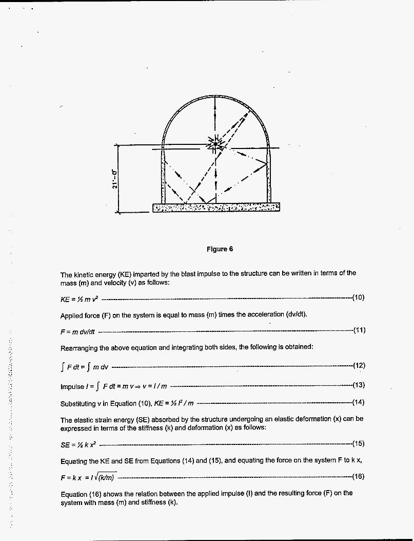
Figure 6
The kinetic energy (KE) imparted by the blast impulse to the structure can be written in terms of the mass (m) and velocity (v) as follows:
Applied force (F) on the system is equal to mass (m) times the acceleration (dv/dt).
. . Rearranging the above equation and integrating both sides, the following is obtained:
. I
The elastic strain energy (SE) absorbed by the structure undergoing an elastic deformation (x) can be expressed in terms of the stiffness (k) and deformation (x) as follows:
Equating the KE and SE from Equations (14) and (15), and equating the force on the system F to k x,
Equation (16) shows the relation between the applied impulse (I) and the resulting force (F) on the system with mass (rn) and stiffness (k).

Note that the deformation of the structure is restricted within the elastic range. However, it is a common practice to let the structure deform many times the elastic limit for impulsive loads.
Results:
The force due to blast impulse loading along the height of the structure was obtained from Equation (16). This force was compared with the weight of the soil mass on top of the dome. The weight of the 'soil on top of the dome was found to be more than adequate to counteract the outward pressure created by the blast overpressure.
The force due to blast impulse loading along the radial direction of the structure was also obtained from Equation (16). This force is resisted by the radial reinforcement in the cylindrical wall. The tensile strength of the concrete is conservatively not considered in resisting the radial strain. Due to uncertainty in the amount of compaction, the passive lateral pressure from the soil mass outside the concrete wall is also ignored while calculating the wall resistance. However, depending on the degree of compaction, the confining soil pressure on the wall can be included in the calculation of resistance to outward pressure from the blast overpressure.
The results of the evaluation are summarized in Table 2 below:
Table 2. Evaluation Results
Max. Demand Remarks
weight of the overburden only ~~ ~
Along the Radial Direction I 31.30 kips/feet Capacity is developed through
the tension in the reinforcing steel only -
For a structure of the given size and shape, the amount of blast overpressure was not large enough to create any significant structural deformation. Moreover, the existing compressive stress field produced by the soil overburden provided an excellent resistance against outward blast overpressure.
It is well known that the underground structures are particularly resistant to external blast loadings. When the underground structures are subjected to internal blast loadings, the confining soil pressure tends to counteract the outward blast overpressure. Therefore the confining soil pressure makes the structure even more resistant to blast loading. The confining soil pressures on an underground structure depend upon the geometry of the structure placement in the surrounding soWrock, and the characteristics (cohesion, angle of internal friction, wall friction, etc.) of the soil, so expertise in geotechnical engineering is required to determine this confining soil pressure. If we go one step further and have an underground structure with cylindrical wall and dome roof like the one in the study, we can also benefit from the compression mode loading from the confining soil pressure. For deeply buried spherical dome like structures, the flexural mode may be completely ignored since the surrounding soil prevents any significant flexural distortion. Also, additional soil mass from the overburden tends to increase the natural period which directs the blast loading to the impulsive regime, thus reducing the analytical complication. Therefore, depending upon the depth of overburden, this type of structure can effectively resist the overpressure from a large internal explosion.
M98001528 ’ I11111111 Ill 11111 llllllllll1111111111 lllil1111111111111
Publ. Date (11) f yy 7/L I - #
Sponsor Code (18) OU? ; j x h E . , uc Category (19) I / C -OB0
19980622 004
DOE

. References:
1. Henry Ayvazyan et al “Structures to Resist the Effect of Accidental Explosives, Volume II - Blast Fragments and Shock Loads”, Special Publication ARLCD-SP-84001 (TM5-1300 Volume ll), USA,1986
2. United States Department of Energy, Albuquerque Operations Office, “A Manual for the Prediction of Blast and Fragment Loadings on Structures”, DOEKIC-11268, USA, 1982
3. G. C. Mays and P. D. Smith ” Blast Effects on Buildings” Thomas Telford Publications, London, England, 1995
4. John M. Biggs “Introduction to Structural Dynamics” McGraw-Hill Book Company, USA, 1964
5. Michael Dede et al “Structures to Resist the Effect of Accidental Explosives, Volume Ill - Principles of Dynamic Analysis”, Special Publication ARLCD-SP-84001 (TM5-1300 Volume Ill), USA, 1984