Embed Size (px)
Citation preview
332245HEN
Instructions-Parts
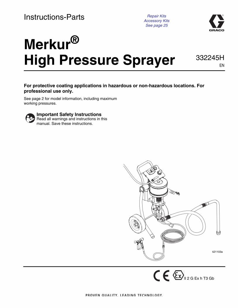
Merkur®
High Pressure Sprayer
For protective coating applications in hazardous or non-hazardous locations. Forprofessional use only.
See page 2 for model information, including maximumworking pressures.
Important Safety InstructionsRead all warnings and instructions in thismanual. Save these instructions.
ti21103a
ll 2 G Ex h T3 Gb
Repair KitsAccessory KitsSee page 25
Related Manuals
2 332245H
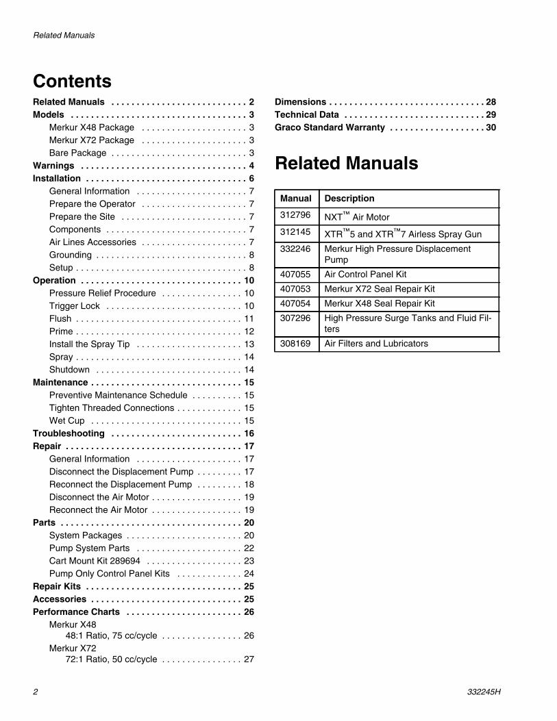
ContentsRelated Manuals . . . . . . . . . . . . . . . . . . . . . . . . . . . 2Models . . . . . . . . . . . . . . . . . . . . . . . . . . . . . . . . . . . 3
Merkur X48 Package . . . . . . . . . . . . . . . . . . . . . 3Merkur X72 Package . . . . . . . . . . . . . . . . . . . . . 3Bare Package . . . . . . . . . . . . . . . . . . . . . . . . . . . 3
Warnings . . . . . . . . . . . . . . . . . . . . . . . . . . . . . . . . . 4Installation . . . . . . . . . . . . . . . . . . . . . . . . . . . . . . . . 6
General Information . . . . . . . . . . . . . . . . . . . . . . 7Prepare the Operator . . . . . . . . . . . . . . . . . . . . . 7Prepare the Site . . . . . . . . . . . . . . . . . . . . . . . . . 7Components . . . . . . . . . . . . . . . . . . . . . . . . . . . . 7Air Lines Accessories . . . . . . . . . . . . . . . . . . . . . 7Grounding . . . . . . . . . . . . . . . . . . . . . . . . . . . . . . 8Setup . . . . . . . . . . . . . . . . . . . . . . . . . . . . . . . . . . 8
Operation . . . . . . . . . . . . . . . . . . . . . . . . . . . . . . . . 10Pressure Relief Procedure . . . . . . . . . . . . . . . . 10Trigger Lock . . . . . . . . . . . . . . . . . . . . . . . . . . . 10Flush . . . . . . . . . . . . . . . . . . . . . . . . . . . . . . . . . 11Prime . . . . . . . . . . . . . . . . . . . . . . . . . . . . . . . . . 12Install the Spray Tip . . . . . . . . . . . . . . . . . . . . . 13Spray . . . . . . . . . . . . . . . . . . . . . . . . . . . . . . . . . 14Shutdown . . . . . . . . . . . . . . . . . . . . . . . . . . . . . 14
Maintenance . . . . . . . . . . . . . . . . . . . . . . . . . . . . . . 15Preventive Maintenance Schedule . . . . . . . . . . 15Tighten Threaded Connections . . . . . . . . . . . . . 15Wet Cup . . . . . . . . . . . . . . . . . . . . . . . . . . . . . . 15
Troubleshooting . . . . . . . . . . . . . . . . . . . . . . . . . . 16Repair . . . . . . . . . . . . . . . . . . . . . . . . . . . . . . . . . . . 17
General Information . . . . . . . . . . . . . . . . . . . . . 17Disconnect the Displacement Pump . . . . . . . . . 17Reconnect the Displacement Pump . . . . . . . . . 18Disconnect the Air Motor . . . . . . . . . . . . . . . . . . 19Reconnect the Air Motor . . . . . . . . . . . . . . . . . . 19
Parts . . . . . . . . . . . . . . . . . . . . . . . . . . . . . . . . . . . . 20System Packages . . . . . . . . . . . . . . . . . . . . . . . 20Pump System Parts . . . . . . . . . . . . . . . . . . . . . 22Cart Mount Kit 289694 . . . . . . . . . . . . . . . . . . . 23Pump Only Control Panel Kits . . . . . . . . . . . . . 24
Repair Kits . . . . . . . . . . . . . . . . . . . . . . . . . . . . . . . 25Accessories . . . . . . . . . . . . . . . . . . . . . . . . . . . . . . 25Performance Charts . . . . . . . . . . . . . . . . . . . . . . . 26
Merkur X4848:1 Ratio, 75 cc/cycle . . . . . . . . . . . . . . . . 26
Merkur X7272:1 Ratio, 50 cc/cycle . . . . . . . . . . . . . . . . 27
Dimensions . . . . . . . . . . . . . . . . . . . . . . . . . . . . . . . 28Technical Data . . . . . . . . . . . . . . . . . . . . . . . . . . . . 29Graco Standard Warranty . . . . . . . . . . . . . . . . . . . 30
Related Manuals
Manual Description
312796 NXT™ Air Motor
312145 XTR™5 and XTR™7 Airless Spray Gun
332246 Merkur High Pressure DisplacementPump
407055 Air Control Panel Kit
407053 Merkur X72 Seal Repair Kit
407054 Merkur X48 Seal Repair Kit
307296 High Pressure Surge Tanks and Fluid Fil-ters
308169 Air Filters and Lubricators
Models
332245H 3
Models
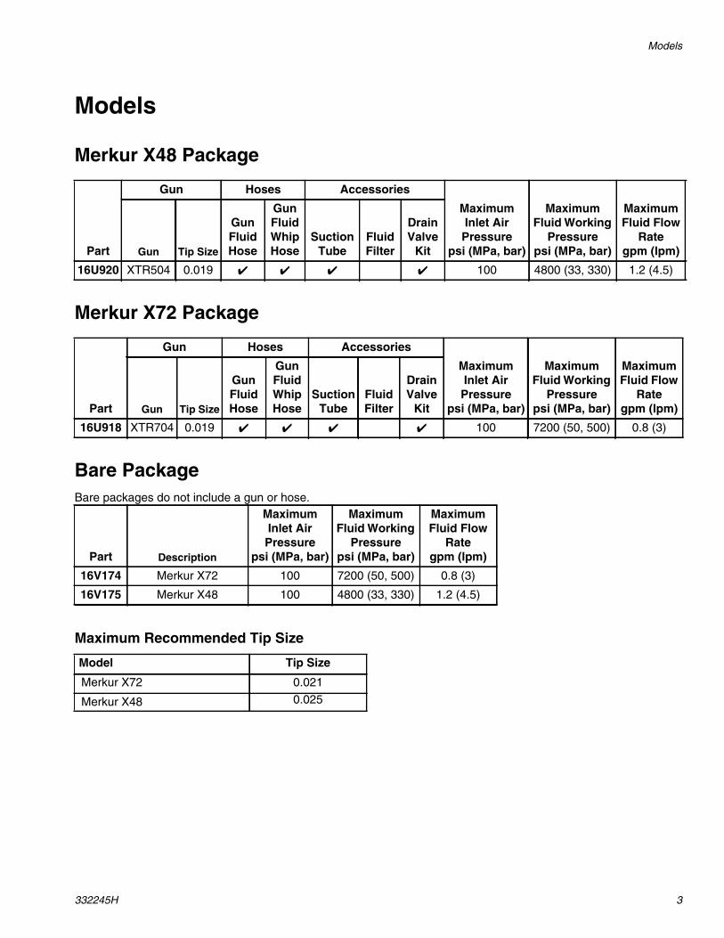
Merkur X48 Package
Merkur X72 Package
Bare PackageBare packages do not include a gun or hose.
Maximum Recommended Tip Size
Part
Gun Hoses Accessories
MaximumInlet Air
Pressurepsi (MPa, bar)
MaximumFluid Working
Pressurepsi (MPa, bar)
MaximumFluid Flow
Rategpm (lpm)Gun Tip Size
GunFluidHose
GunFluidWhipHose
SuctionTube
FluidFilter
DrainValve
Kit
16U920 XTR504 0.019 ✔ ✔ ✔ ✔ 100 4800 (33, 330) 1.2 (4.5)
Part
Gun Hoses Accessories
MaximumInlet Air
Pressurepsi (MPa, bar)
MaximumFluid Working
Pressurepsi (MPa, bar)
MaximumFluid Flow
Rategpm (lpm)Gun Tip Size
GunFluidHose
GunFluidWhipHose
SuctionTube
FluidFilter
DrainValve
Kit
16U918 XTR704 0.019 ✔ ✔ ✔ ✔ 100 7200 (50, 500) 0.8 (3)
Part Description
MaximumInlet AirPressure
psi (MPa, bar)
MaximumFluid Working
Pressurepsi (MPa, bar)
MaximumFluid Flow
Rategpm (lpm)
16V174 Merkur X72 100 7200 (50, 500) 0.8 (3)
16V175 Merkur X48 100 4800 (33, 330) 1.2 (4.5)
Model Tip Size
Merkur X72 0.021
Merkur X48 0.025
Warnings
4 332245H
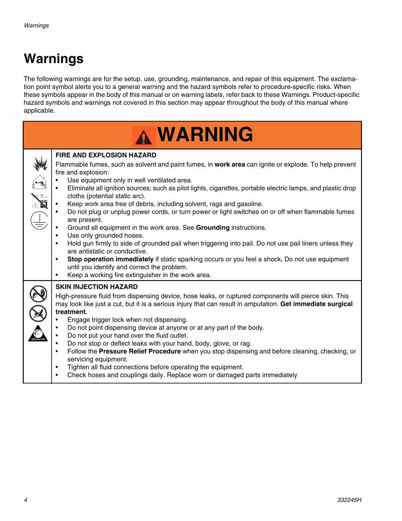
WarningsThe following warnings are for the setup, use, grounding, maintenance, and repair of this equipment. The exclama-tion point symbol alerts you to a general warning and the hazard symbols refer to procedure-specific risks. Whenthese symbols appear in the body of this manual or on warning labels, refer back to these Warnings. Product-specifichazard symbols and warnings not covered in this section may appear throughout the body of this manual whereapplicable.
WARNINGFIRE AND EXPLOSION HAZARDFlammable fumes, such as solvent and paint fumes, in work area can ignite or explode. To help preventfire and explosion:• Use equipment only in well ventilated area.• Eliminate all ignition sources; such as pilot lights, cigarettes, portable electric lamps, and plastic drop
cloths (potential static arc).• Keep work area free of debris, including solvent, rags and gasoline.• Do not plug or unplug power cords, or turn power or light switches on or off when flammable fumes
are present.• Ground all equipment in the work area. See Grounding instructions.• Use only grounded hoses.• Hold gun firmly to side of grounded pail when triggering into pail. Do not use pail liners unless they
are antistatic or conductive.• Stop operation immediately if static sparking occurs or you feel a shock. Do not use equipment
until you identify and correct the problem.• Keep a working fire extinguisher in the work area.
SKIN INJECTION HAZARDHigh-pressure fluid from dispensing device, hose leaks, or ruptured components will pierce skin. Thismay look like just a cut, but it is a serious injury that can result in amputation. Get immediate surgicaltreatment.• Engage trigger lock when not dispensing.• Do not point dispensing device at anyone or at any part of the body.• Do not put your hand over the fluid outlet.• Do not stop or deflect leaks with your hand, body, glove, or rag.• Follow the Pressure Relief Procedure when you stop dispensing and before cleaning, checking, or
servicing equipment.• Tighten all fluid connections before operating the equipment.• Check hoses and couplings daily. Replace worn or damaged parts immediately
Warnings
332245H 5
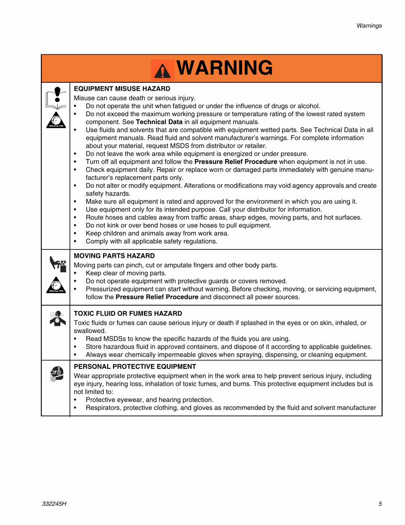
EQUIPMENT MISUSE HAZARDMisuse can cause death or serious injury.• Do not operate the unit when fatigued or under the influence of drugs or alcohol.• Do not exceed the maximum working pressure or temperature rating of the lowest rated system
component. See Technical Data in all equipment manuals.• Use fluids and solvents that are compatible with equipment wetted parts. See Technical Data in all
equipment manuals. Read fluid and solvent manufacturer’s warnings. For complete informationabout your material, request MSDS from distributor or retailer.
• Do not leave the work area while equipment is energized or under pressure.• Turn off all equipment and follow the Pressure Relief Procedure when equipment is not in use.• Check equipment daily. Repair or replace worn or damaged parts immediately with genuine manu-
facturer’s replacement parts only.• Do not alter or modify equipment. Alterations or modifications may void agency approvals and create
safety hazards.• Make sure all equipment is rated and approved for the environment in which you are using it.• Use equipment only for its intended purpose. Call your distributor for information.• Route hoses and cables away from traffic areas, sharp edges, moving parts, and hot surfaces.• Do not kink or over bend hoses or use hoses to pull equipment.• Keep children and animals away from work area.• Comply with all applicable safety regulations.
MOVING PARTS HAZARDMoving parts can pinch, cut or amputate fingers and other body parts.• Keep clear of moving parts.• Do not operate equipment with protective guards or covers removed.• Pressurized equipment can start without warning. Before checking, moving, or servicing equipment,
follow the Pressure Relief Procedure and disconnect all power sources.
TOXIC FLUID OR FUMES HAZARDToxic fluids or fumes can cause serious injury or death if splashed in the eyes or on skin, inhaled, orswallowed.• Read MSDSs to know the specific hazards of the fluids you are using.• Store hazardous fluid in approved containers, and dispose of it according to applicable guidelines.• Always wear chemically impermeable gloves when spraying, dispensing, or cleaning equipment.
PERSONAL PROTECTIVE EQUIPMENTWear appropriate protective equipment when in the work area to help prevent serious injury, includingeye injury, hearing loss, inhalation of toxic fumes, and burns. This protective equipment includes but isnot limited to:• Protective eyewear, and hearing protection.• Respirators, protective clothing, and gloves as recommended by the fluid and solvent manufacturer
WARNING
Installation
6 332245H
Installation
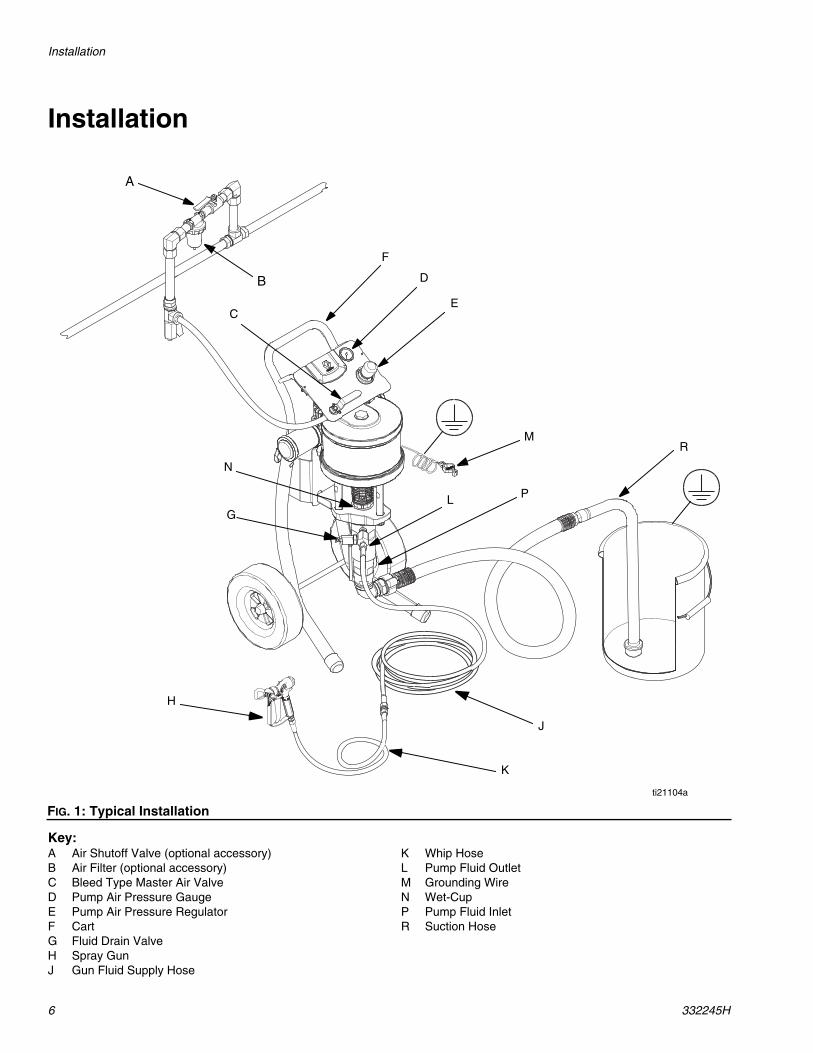
Key:A Air Shutoff Valve (optional accessory)B Air Filter (optional accessory)C Bleed Type Master Air ValveD Pump Air Pressure GaugeE Pump Air Pressure RegulatorF CartG Fluid Drain ValveH Spray GunJ Gun Fluid Supply Hose
K Whip HoseL Pump Fluid OutletM Grounding WireN Wet-CupP Pump Fluid InletR Suction Hose
FIG. 1: Typical Installation
D
PL
C
M
K
E
R
J
H
F
N
ti21104a
G
B
A
Installation
332245H 7
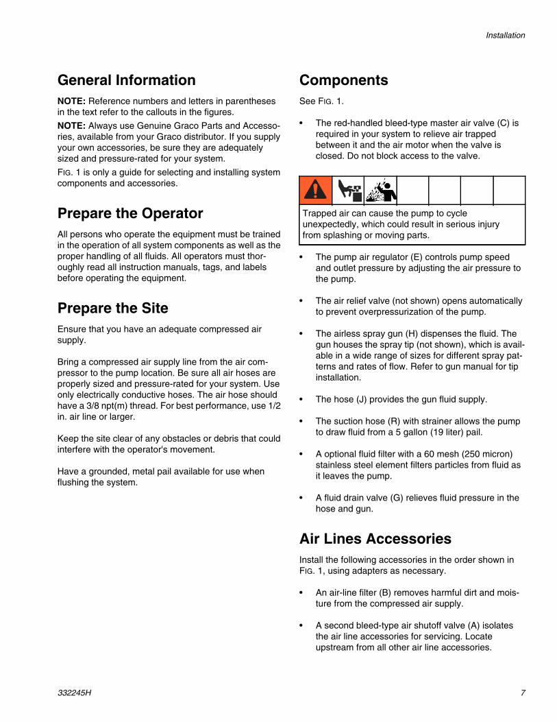
General InformationNOTE: Reference numbers and letters in parenthesesin the text refer to the callouts in the figures.
NOTE: Always use Genuine Graco Parts and Accesso-ries, available from your Graco distributor. If you supplyyour own accessories, be sure they are adequatelysized and pressure-rated for your system.
FIG. 1 is only a guide for selecting and installing systemcomponents and accessories.
Prepare the OperatorAll persons who operate the equipment must be trainedin the operation of all system components as well as theproper handling of all fluids. All operators must thor-oughly read all instruction manuals, tags, and labelsbefore operating the equipment.
Prepare the SiteEnsure that you have an adequate compressed airsupply.
Bring a compressed air supply line from the air com-pressor to the pump location. Be sure all air hoses areproperly sized and pressure-rated for your system. Useonly electrically conductive hoses. The air hose shouldhave a 3/8 npt(m) thread. For best performance, use 1/2in. air line or larger.
Keep the site clear of any obstacles or debris that couldinterfere with the operator's movement.
Have a grounded, metal pail available for use whenflushing the system.
ComponentsSee FIG. 1.
• The red-handled bleed-type master air valve (C) isrequired in your system to relieve air trappedbetween it and the air motor when the valve isclosed. Do not block access to the valve.
• The pump air regulator (E) controls pump speedand outlet pressure by adjusting the air pressure tothe pump.
• The air relief valve (not shown) opens automaticallyto prevent overpressurization of the pump.
• The airless spray gun (H) dispenses the fluid. Thegun houses the spray tip (not shown), which is avail-able in a wide range of sizes for different spray pat-terns and rates of flow. Refer to gun manual for tipinstallation.
• The hose (J) provides the gun fluid supply.
• The suction hose (R) with strainer allows the pumpto draw fluid from a 5 gallon (19 liter) pail.
• A optional fluid filter with a 60 mesh (250 micron)stainless steel element filters particles from fluid asit leaves the pump.
• A fluid drain valve (G) relieves fluid pressure in thehose and gun.
Air Lines AccessoriesInstall the following accessories in the order shown inFIG. 1, using adapters as necessary.
• An air-line filter (B) removes harmful dirt and mois-ture from the compressed air supply.
• A second bleed-type air shutoff valve (A) isolatesthe air line accessories for servicing. Locateupstream from all other air line accessories.
Trapped air can cause the pump to cycleunexpectedly, which could result in serious injuryfrom splashing or moving parts.
Installation
8 332245H
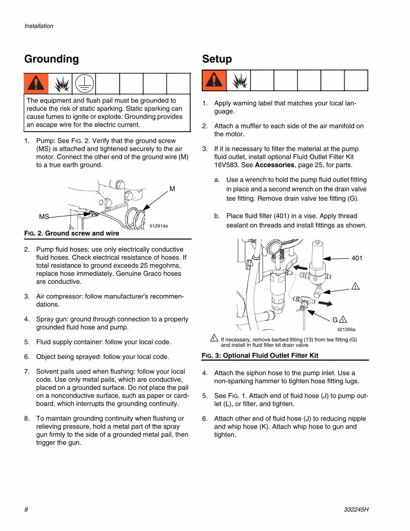
Grounding
1. Pump: See FIG. 2. Verify that the ground screw(MS) is attached and tightened securely to the airmotor. Connect the other end of the ground wire (M)to a true earth ground.
2. Pump fluid hoses: use only electrically conductivefluid hoses. Check electrical resistance of hoses. Iftotal resistance to ground exceeds 25 megohms,replace hose immediately. Genuine Graco hosesare conductive.
3. Air compressor: follow manufacturer's recommen-dations.
4. Spray gun: ground through connection to a properlygrounded fluid hose and pump.
5. Fluid supply container: follow your local code.
6. Object being sprayed: follow your local code.
7. Solvent pails used when flushing: follow your localcode. Use only metal pails, which are conductive,placed on a grounded surface. Do not place the pailon a nonconductive surface, such as paper or card-board, which interrupts the grounding continuity.
8. To maintain grounding continuity when flushing orrelieving pressure, hold a metal part of the spraygun firmly to the side of a grounded metal pail, thentrigger the gun.
Setup
1. Apply warning label that matches your local lan-guage.
2. Attach a muffler to each side of the air manifold onthe motor.
3. If it is necessary to filter the material at the pumpfluid outlet, install optional Fluid Outlet Filter Kit16V583. See Accessories, page 25, for parts.
a. Use a wrench to hold the pump fluid outlet fittingin place and a second wrench on the drain valvetee fitting. Remove drain valve tee fitting (G).
b. Place fluid filter (401) in a vise. Apply threadsealant on threads and install fittings as shown.
4. Attach the siphon hose to the pump inlet. Use anon-sparking hammer to tighten hose fitting lugs.
5. See FIG. 1. Attach end of fluid hose (J) to pump out-let (L), or filter, and tighten.
6. Attach other end of fluid hose (J) to reducing nippleand whip hose (K). Attach whip hose to gun andtighten.
The equipment and flush pail must be grounded toreduce the risk of static sparking. Static sparking cancause fumes to ignite or explode. Grounding providesan escape wire for the electric current.
FIG. 2. Ground screw and wire
M
MSti12914a
FIG. 3: Optional Fluid Outlet Filter Kit
If necessary, remove barbed fitting (13) from tee fitting (G)and install in fluid filter kit drain valve.
1
ti21356a
G
401
1
1
Installation
332245H 9
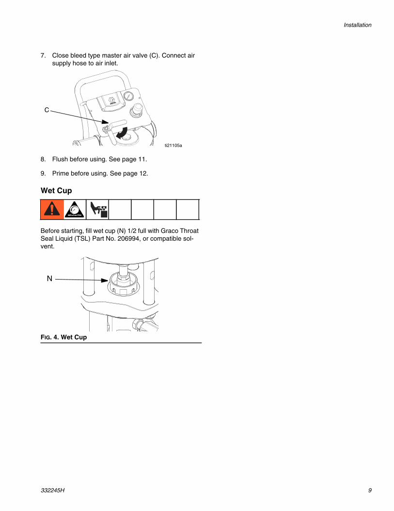
7. Close bleed type master air valve (C). Connect airsupply hose to air inlet.
8. Flush before using. See page 11.
9. Prime before using. See page 12.
Wet Cup
Before starting, fill wet cup (N) 1/2 full with Graco ThroatSeal Liquid (TSL) Part No. 206994, or compatible sol-vent.
FIG. 4. Wet Cup
ti21105a
C
N
Operation
10 332245H
Operation
Pressure Relief ProcedureFollow the Pressure Relief Procedure wheneveryou see this symbol.
1. Engage the trigger lock.
2. See FIG. 1. Turn off the bleed-type master air valve(C).
3. Disengage the trigger lock.
4. Hold a metal part of the gun firmly to a groundedmetal waste container. Trigger the gun to relievefluid pressure.
5. Engage the trigger lock.
6. Open all fluid drain valves in the system, having awaste container ready to catch the drainage. Afterthe fluid is drained, close the valves.
7. If you suspect the spray tip or hose is completelyclogged, or that pressure has not been fully relievedafter following the previous steps, very slowlyloosen the tip guard retaining nut or hose end cou-pling and relieve pressure gradually; then loosencompletely. With tip removed, trigger gun intobucket.
Trigger Lock
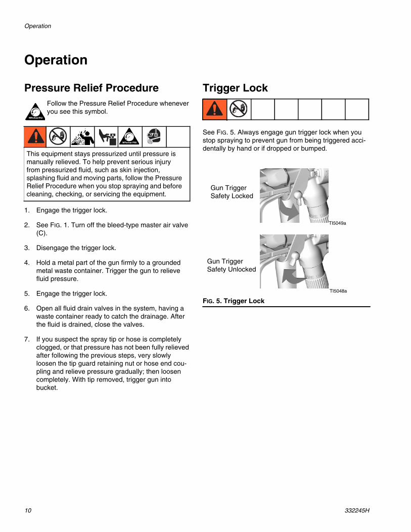
See FIG. 5. Always engage gun trigger lock when youstop spraying to prevent gun from being triggered acci-dentally by hand or if dropped or bumped.
This equipment stays pressurized until pressure ismanually relieved. To help prevent serious injuryfrom pressurized fluid, such as skin injection,splashing fluid and moving parts, follow the PressureRelief Procedure when you stop spraying and beforecleaning, checking, or servicing the equipment.
FIG. 5. Trigger Lock
TI5049a
TI5048a
Gun TriggerSafety Locked
Gun TriggerSafety Unlocked
Operation
332245H 11
Flush
Flush the Pump Before First Use
The pump is tested with lightweight oil, which is left in toprotect the pump parts. If the fluid you are using may becontaminated by the oil, flush it out with a compatiblesolvent. See Flush on page 11.
Flush the pump:
• Before first use
• When changing colors or fluids
• Before repairing equipment
• Before fluid dries or settles out in a dormant pump(check the pot life of catalyzed fluids)
• At the end of the day
• Before storing the pump.
Flush at the lowest pressure possible. Flush with a fluidthat is compatible with the fluid you are pumping andwith the wetted parts in your system. Check with yourfluid manufacturer or supplier for recommended flushingfluids and flushing frequency.
1. Follow Pressure Relief Procedure, page 10.
2. See FIG. 1. Lock gun trigger. Remove tip guard andspray tip from gun (H). Refer to gun manual.
3. Place suction tube in a compatible solvent.
NOTE: Do not stretch hose tight; let it hang to assistfluid flow into pump.
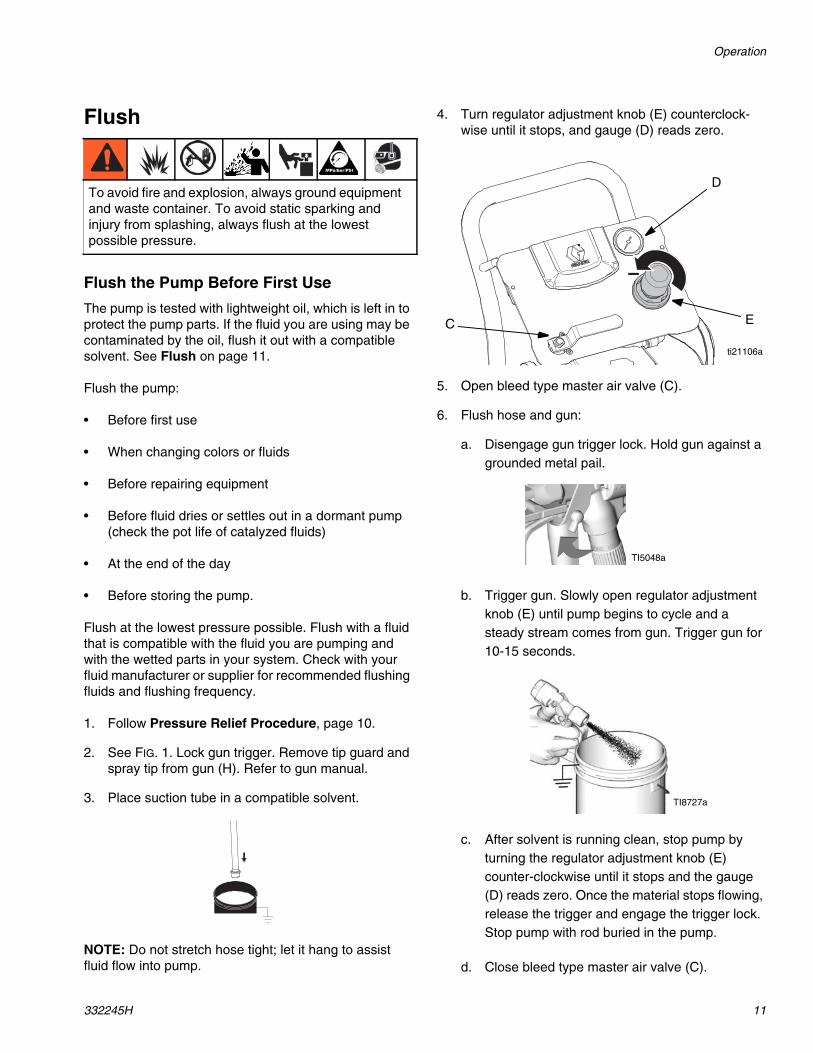
4. Turn regulator adjustment knob (E) counterclock-wise until it stops, and gauge (D) reads zero.
5. Open bleed type master air valve (C).
6. Flush hose and gun:
a. Disengage gun trigger lock. Hold gun against agrounded metal pail.
b. Trigger gun. Slowly open regulator adjustmentknob (E) until pump begins to cycle and asteady stream comes from gun. Trigger gun for10-15 seconds.
c. After solvent is running clean, stop pump byturning the regulator adjustment knob (E)counter-clockwise until it stops and the gauge(D) reads zero. Once the material stops flowing,release the trigger and engage the trigger lock.Stop pump with rod buried in the pump.
d. Close bleed type master air valve (C).
To avoid fire and explosion, always ground equipmentand waste container. To avoid static sparking andinjury from splashing, always flush at the lowestpossible pressure.
E
D
ti21106a
C
TI5048a
TI8727a
Operation
12 332245H
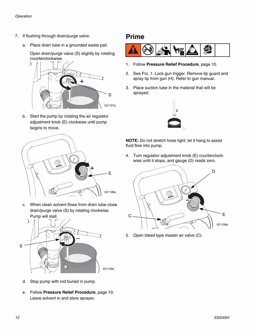
7. If flushing through drain/purge valve:
a. Place drain tube in a grounded waste pail.
Open drain/purge valve (S) slightly by rotatingcounterclockwise.
b. Start the pump by rotating the air regulatoradjustment knob (E) clockwise until pumpbegins to move.
c. When clean solvent flows from drain tube closedrain/purge valve (S) by rotating clockwise.Pump will stall.
d. Stop pump with rod buried in pump.
e. Follow Pressure Relief Procedure, page 10.Leave solvent in and store sprayer.
Prime
1. Follow Pressure Relief Procedure, page 10.
2. See FIG. 1. Lock gun trigger. Remove tip guard andspray tip from gun (H). Refer to gun manual.
3. Place suction tube in the material that will besprayed.
NOTE: Do not stretch hose tight; let it hang to assistfluid flow into pump.
4. Turn regulator adjustment knob (E) counterclock-wise until it stops, and gauge (D) reads zero.
5. Open bleed type master air valve (C).
S
ti21107a
E
ti21108a
S
ti21109a
E
D
ti21106a
C
Operation
332245H 13
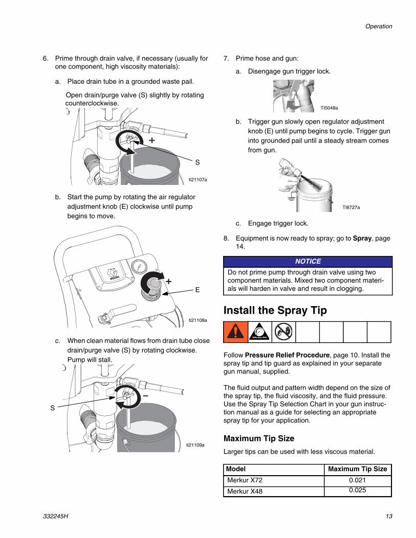
6. Prime through drain valve, if necessary (usually forone component, high viscosity materials):
a. Place drain tube in a grounded waste pail.
Open drain/purge valve (S) slightly by rotatingcounterclockwise.
b. Start the pump by rotating the air regulatoradjustment knob (E) clockwise until pumpbegins to move.
c. When clean material flows from drain tube closedrain/purge valve (S) by rotating clockwise.Pump will stall.
7. Prime hose and gun:
a. Disengage gun trigger lock.
b. Trigger gun slowly open regulator adjustmentknob (E) until pump begins to cycle. Trigger guninto grounded pail until a steady stream comesfrom gun.
c. Engage trigger lock.
8. Equipment is now ready to spray; go to Spray, page14.
Install the Spray Tip
Follow Pressure Relief Procedure, page 10. Install thespray tip and tip guard as explained in your separategun manual, supplied.
The fluid output and pattern width depend on the size ofthe spray tip, the fluid viscosity, and the fluid pressure.Use the Spray Tip Selection Chart in your gun instruc-tion manual as a guide for selecting an appropriatespray tip for your application.
Maximum Tip Size
Larger tips can be used with less viscous material.
S
ti21107a
E
ti21108a
S
ti21109a
NOTICE
Do not prime pump through drain valve using twocomponent materials. Mixed two component materi-als will harden in valve and result in clogging.
Model Maximum Tip Size
Merkur X72 0.021
Merkur X48 0.025
TI5048a
TI8727a
Operation
14 332245H
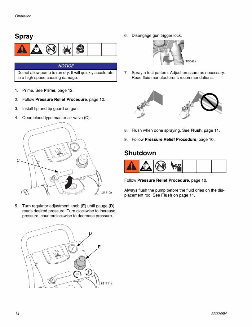
Spray
1. Prime. See Prime, page 12.
2. Follow Pressure Relief Procedure, page 10.
3. Install tip and tip guard on gun.
4. Open bleed type master air valve (C).
5. Turn regulator adjustment knob (E) until gauge (D)reads desired pressure. Turn clockwise to increasepressure, counterclockwise to decrease pressure.
6. Disengage gun trigger lock.
7. Spray a test pattern. Adjust pressure as necessary.Read fluid manufacturer’s recommendations.
8. Flush when done spraying. See Flush, page 11.
9. Follow Pressure Relief Procedure, page 10.
Shutdown
Follow Pressure Relief Procedure, page 10.
Always flush the pump before the fluid dries on the dis-placement rod. See Flush on page 11.
NOTICE
Do not allow pump to run dry. It will quickly accelerateto a high speed causing damage.
C
ti21110a
E
D
ti21111a
TI5048a
Maintenance
332245H 15
Maintenance
Preventive MaintenanceScheduleThe operating conditions of your particular systemdetermine how often maintenance is required. Establisha preventive maintenance schedule by recording whenand what kind of maintenance is needed, and thendetermine a regular schedule for checking your system.
Replace lens covers on regulator gauge lenses whendirt makes gauges difficult to read.
Tighten Threaded ConnectionsBefore each use, check all hoses for wear or damage.Replace as necessary. Check that all threaded connec-tions are tight and leak-free.
Wet CupFill the wet cup one-half full with Graco Throat Seal Liq-uid (TSL). Maintain level daily.
Troubleshooting
16 332245H
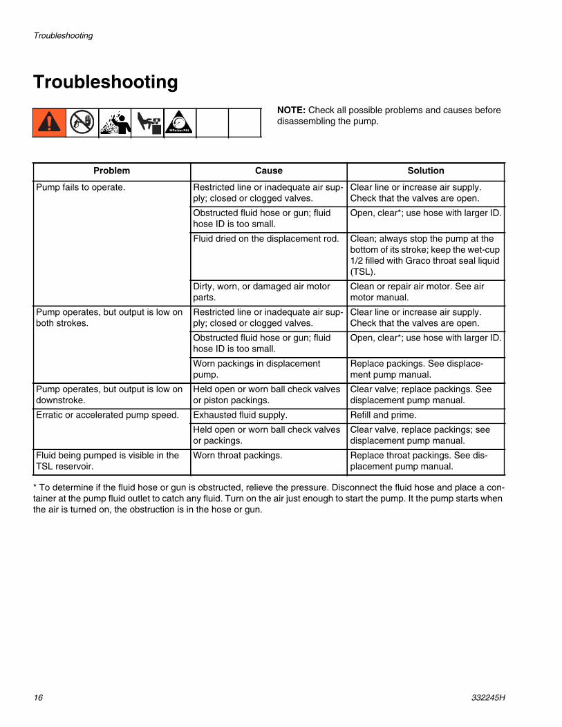
TroubleshootingNOTE: Check all possible problems and causes beforedisassembling the pump.
* To determine if the fluid hose or gun is obstructed, relieve the pressure. Disconnect the fluid hose and place a con-tainer at the pump fluid outlet to catch any fluid. Turn on the air just enough to start the pump. It the pump starts whenthe air is turned on, the obstruction is in the hose or gun.
Problem Cause Solution
Pump fails to operate. Restricted line or inadequate air sup-ply; closed or clogged valves.
Clear line or increase air supply.Check that the valves are open.
Obstructed fluid hose or gun; fluidhose ID is too small.
Open, clear*; use hose with larger ID.
Fluid dried on the displacement rod. Clean; always stop the pump at thebottom of its stroke; keep the wet-cup1/2 filled with Graco throat seal liquid(TSL).
Dirty, worn, or damaged air motorparts.
Clean or repair air motor. See airmotor manual.
Pump operates, but output is low onboth strokes.
Restricted line or inadequate air sup-ply; closed or clogged valves.
Clear line or increase air supply.Check that the valves are open.
Obstructed fluid hose or gun; fluidhose ID is too small.
Open, clear*; use hose with larger ID.
Worn packings in displacementpump.
Replace packings. See displace-ment pump manual.
Pump operates, but output is low ondownstroke.
Held open or worn ball check valvesor piston packings.
Clear valve; replace packings. Seedisplacement pump manual.
Erratic or accelerated pump speed. Exhausted fluid supply. Refill and prime.
Held open or worn ball check valvesor packings.
Clear valve, replace packings; seedisplacement pump manual.
Fluid being pumped is visible in theTSL reservoir.
Worn throat packings. Replace throat packings. See dis-placement pump manual.
Repair
332245H 17
Repair
General Information• Reference numbers and letters in parentheses in
the text refer to the callouts in the figures and theparts drawing.
• Always use Genuine Graco Parts and Accessories,available from your Graco distributor. If you supplyyour own accessories, be sure they are adequatelysized and pressure rated for your system.
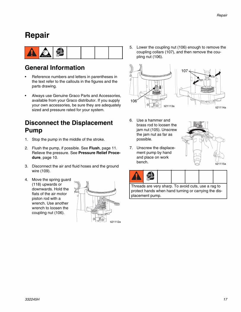
Disconnect the DisplacementPump1. Stop the pump in the middle of the stroke.
2. Flush the pump, if possible. See Flush, page 11.Relieve the pressure. See Pressure Relief Proce-dure, page 10.
3. Disconnect the air and fluid hoses and the groundwire (109).
4. Move the spring guard(118) upwards ordownwards. Hold theflats of the air motorpiston rod with awrench. Use anotherwrench to loosen thecoupling nut (106).
5. Lower the coupling nut (106) enough to remove thecoupling collars (107), and then remove the cou-pling nut (106).
6. Use a hammer andbrass rod to loosen thejam nut (105). Unscrewthe jam nut as far aspossible.
7. Unscrew the displace-ment pump by handand place on workbench.
ti21112a
Threads are very sharp. To avoid cuts, use a rag toprotect hands when hand turning or carrying the dis-placement pump.
ti21113a ti21114a
106
107
ti21115a
Repair
18 332245H
Reconnect the DisplacementPump1. Tilt the air motor onto its back, then hand turn the
displacement pump into the adapter plate. Set thepump upright again.
2. Hold the air motor piston rod up with one hand. Withyour other hand, put the coupling nut (106) on thedisplacement rod.
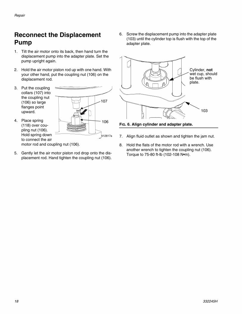
3. Put the couplingcollars (107) intothe coupling nut(106) so largeflanges pointupward.
4. Place spring(118) over cou-pling nut (106).Hold spring downto connect the airmotor rod and coupling nut (106).
5. Gently let the air motor piston rod drop onto the dis-placement rod. Hand tighten the coupling nut (106).
6. Screw the displacement pump into the adapter plate(103) until the cylinder top is flush with the top of theadapter plate.
7. Align fluid outlet as shown and tighten the jam nut.
8. Hold the flats of the motor rod with a wrench. Useanother wrench to tighten the coupling nut (106).Torque to 75-80 ft-lb (102-108 N•m).
ti12817a
107
106FIG. 6. Align cylinder and adapter plate.
Cylinder, not
be flush withplate.
wet cup, should
103
Repair
332245H 19
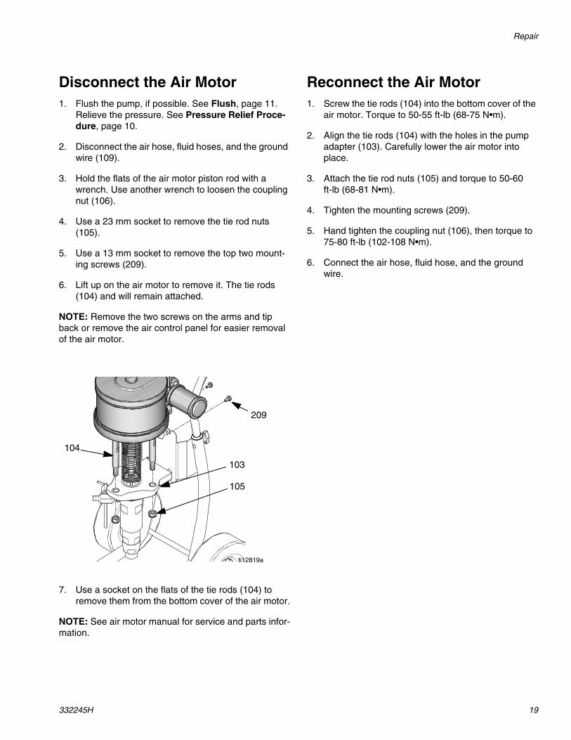
Disconnect the Air Motor1. Flush the pump, if possible. See Flush, page 11.
Relieve the pressure. See Pressure Relief Proce-dure, page 10.
2. Disconnect the air hose, fluid hoses, and the groundwire (109).
3. Hold the flats of the air motor piston rod with awrench. Use another wrench to loosen the couplingnut (106).
4. Use a 23 mm socket to remove the tie rod nuts(105).
5. Use a 13 mm socket to remove the top two mount-ing screws (209).
6. Lift up on the air motor to remove it. The tie rods(104) and will remain attached.
NOTE: Remove the two screws on the arms and tipback or remove the air control panel for easier removalof the air motor.
7. Use a socket on the flats of the tie rods (104) toremove them from the bottom cover of the air motor.
NOTE: See air motor manual for service and parts infor-mation.
Reconnect the Air Motor1. Screw the tie rods (104) into the bottom cover of the
air motor. Torque to 50-55 ft-lb (68-75 N•m).
2. Align the tie rods (104) with the holes in the pumpadapter (103). Carefully lower the air motor intoplace.
3. Attach the tie rod nuts (105) and torque to 50-60ft-lb (68-81 N•m).
4. Tighten the mounting screws (209).
5. Hand tighten the coupling nut (106), then torque to75-80 ft-lb (102-108 N•m).
6. Connect the air hose, fluid hose, and the groundwire.
ti12819a
104
105
103
209
Parts
20 332245H
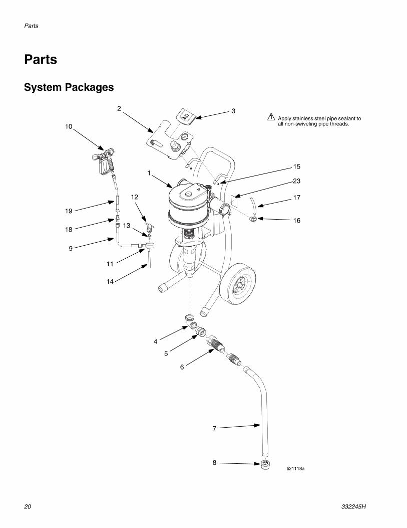
Parts
System Packages
Apply stainless steel pipe sealant toall non-swiveling pipe threads.
1
17
16
32
10
19
18
9
11
14
4
5
6
7
8
1
12
13
15
ti21118a
23
Parts
332245H 21
System Packages
* Parts included in Drain Valve Kit 16U950 (purchase separately).
Ref Part Description
QuantitySystem Packages Bare Packages
16U918,Merkur X7272:1, 50cc
16U920,Merkur X4848:1, 75cc
16V174,Merkur X7272:1, 50cc
16V175,Merkur X4848:1, 75cc
1 ----- SYSTEM, pump, 48:1;see page 22
1 1
----- SYSTEM, pump, 72:1;see page 22
1 1
2 16U947 KIT, air control, X72 1 116U948 KIT, air control, X48 1 1
3 277794 INSERT, control panel 1 1 1 14 116401 ADAPTER, elbow 1 1 1 15 116402 ADAPTER, quick connect 1 1 1 16 247301 HOSE, suction, 1 in. npt x quick
connect1 1 1 1
7 197682 TUBE, suction 1 1 1 18 187147 STRAINER, inlet 1 1 1 19 H53825 HOSE, coupled; 5600 psi, 0.375
in. (9.5 mm) ID, 25 ft (7.6 m)1
H73825 HOSE, coupled; 7250 psi, 0.375in. (9.5 mm) ID, 25 ft (7.6 m)
1
10 XTR504 GUN, XTR5 with RAC tip 1XTR704 GUN, XTR7 with RAC tip 1
11* 15R874 FITTING, tee; 3/8 mxfxf 1 1 1 112* 245143 VALVE, pressure, bleed 1 1 1 113* 116746 FITTING, barbed, plated 1 1 1 114* 116750 TUBE, nylon 1 1 1 115 105332 NUT, lock 2 2 2 216 15V204 FITTING, elbow, 1/2 npt x 1/2
tube1 1 1 1
17 ----- TUBE, nylon; 1/2 OD x 3/8 ID;0.65 ft (0.2 m)
1 1 1 1
18 164856 FITTING, nipple, reducing; 3/8 x1/4 nptm
1 1
19 H52506 HOSE, coupled; 5600 psi, 0.25(6 mm) ID, 6 ft (1.8 m)
1
H72506 HOSE, coupled; 7250 psi, 0.25(6 mm) ID, 6 ft (1.8 m)
1
22 206994 FLUID, TSL 8 oz bottle 1 1 1 123 ----- LABEL, identification 1 1 1 124 ----- COVER, lens, 12 sticker sheet;
(not shown), order Kit 24A540for 5 sheets
1 1 1 1
Parts
22 332245H
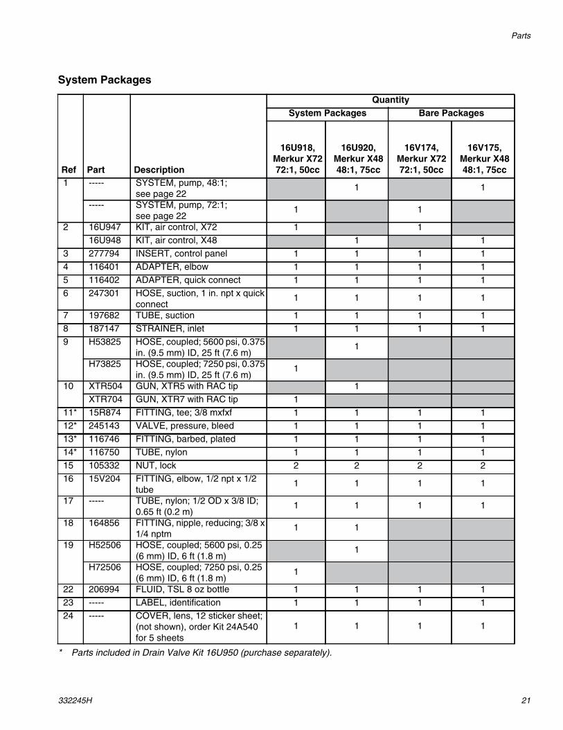
Pump System Parts
101
102
110
ti21119a
Torque to 50-55 ft-lb (68-75 N•m).1
Torque to 50-60 ft-lb (68-81 N•m).2
Torque to 75-80 ft-lb (102-108 N•m).3
Assemble pump (102) to top of within +/-one thread. Torque jam nut of pump to70-75 ft-lb (95-102 N•m).
4
105
104
103
106
107
108
109
1
2
3
4
Parts
332245H 23
16V175, Merkur X48 Pump System16V174, Merkur X72 Pump System
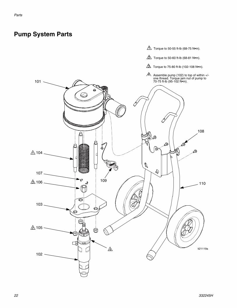
Cart Mount Kit 289694
Ref. Part Description Qty.101 M18LN0 MOTOR, air, 7.5 in 1102 16U916 LOWER, assy, 50cc; 16V174 1
16U917 LOWER, assy, 75cc; 16V175 1103 15T392 ADAPTER, pump lower 1104 15M662 ROD, tie 3105 15U606 NUT, lock, m16 x 2 3106 15T311 NUT, coupler 1107 184128 COLLAR, coupling 2108 111799 SCREW, cap, hex hd 4109 238909 WIRE, grounding assembly 1110 289694 KIT, cart 1118 16U944 GUARD, spring 1
Ref. Part DescriptionQty
.201 ----- CART, frame 1202 ----- HANDLE, cart 1203 15C871 CAP, leg 2204 ----- SLEEVE, cart handle 2205 119451 WHEEL, semi-pneumatic 2206 119452 CAP, hub 2207 115480 KNOB, t-handle 2208 116630 SCREW, carriage 2209 111799 SCREW, cap, M8 x 1.25 4
201
202
203
204
205
206
207
208
209
ti12634a
Parts
24 332245H
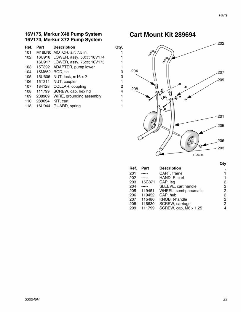
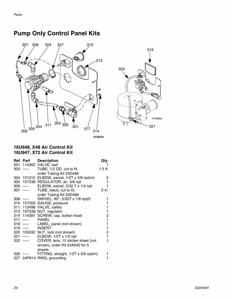
Pump Only Control Panel Kits
16U948, X48 Air Control Kit16U947, X72 Air Control Kit
ti13567a
301303
314317
326311305 304
310
313
306
307 308 304
ti13567b
327319
321
303
ti13468a
Ref. Part Description Qty.301 114362 VALVE, ball 1303 ----- TUBE, 1/2 OD, cut to fit,
order Tubing Kit 24D4961.5 ft.
304 121212 ELBOW, swivel, 1/2T x 3/8 npt(m) 2305 15T536 REGULATOR, air, 3/8 npt 1306 ----- ELBOW, swivel, 5/32 T x 1/4 npt 1307 ----- TUBE, black, cut to fit,
order Tubing Kit 24D4965 in.
308 ----- SWIVEL, 90°, 5/32T x 1/8 npt(f) 1310 15T500 GAUGE, pressure 1311 113498 VALVE, safety 1313 15T538 NUT, regulator 1314 114381 SCREW, cap, button head 2317 ----- PANEL 1318 ----- LABEL, panel (not shown) 1319 ----- INSERT 1320 105332 NUT, lock (not shown) 2321 ----- ELBOW, 1/2T x 1/2 npt 1322 ----- COVER, lens, 12 sticker sheet (not
shown), order Kit 24A540 for 5sheets
1
326 ----- FITTING, straight, 1/2T x 3/8 npt(m) 1327 24P814 RING, grounding 1
Repair Kits
332245H 25
Repair Kits
Accessories
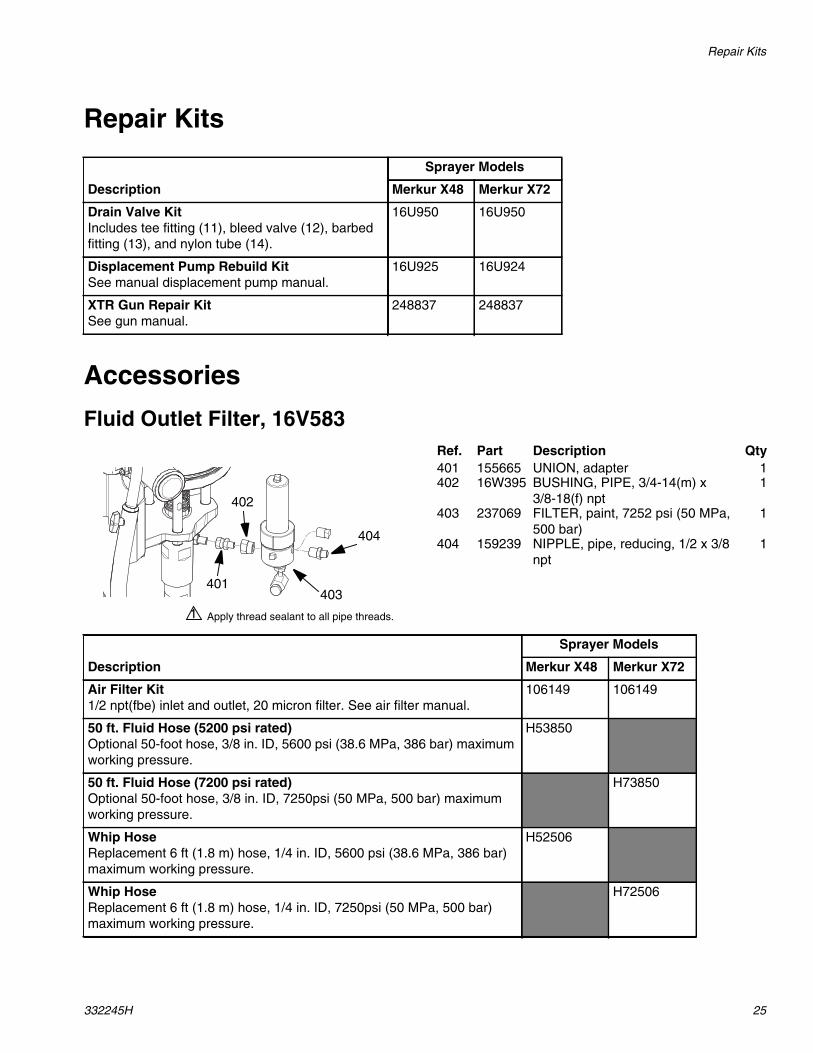
Fluid Outlet Filter, 16V583
Description
Sprayer Models
Merkur X48 Merkur X72
Drain Valve KitIncludes tee fitting (11), bleed valve (12), barbedfitting (13), and nylon tube (14).
16U950 16U950
Displacement Pump Rebuild KitSee manual displacement pump manual.
16U925 16U924
XTR Gun Repair KitSee gun manual.
248837 248837
Apply thread sealant to all pipe threads.1
404
403401
402
Ref. Part Description Qty401 155665 UNION, adapter 1402 16W395 BUSHING, PIPE, 3/4-14(m) x
3/8-18(f) npt1
403 237069 FILTER, paint, 7252 psi (50 MPa,500 bar)
1
404 159239 NIPPLE, pipe, reducing, 1/2 x 3/8npt
1
Description
Sprayer Models
Merkur X48 Merkur X72
Air Filter Kit1/2 npt(fbe) inlet and outlet, 20 micron filter. See air filter manual.
106149 106149
50 ft. Fluid Hose (5200 psi rated)Optional 50-foot hose, 3/8 in. ID, 5600 psi (38.6 MPa, 386 bar) maximumworking pressure.
H53850
50 ft. Fluid Hose (7200 psi rated)Optional 50-foot hose, 3/8 in. ID, 7250psi (50 MPa, 500 bar) maximumworking pressure.
H73850
Whip HoseReplacement 6 ft (1.8 m) hose, 1/4 in. ID, 5600 psi (38.6 MPa, 386 bar)maximum working pressure.
H52506
Whip HoseReplacement 6 ft (1.8 m) hose, 1/4 in. ID, 7250psi (50 MPa, 500 bar)maximum working pressure.
H72506
Performance Charts
26 332245H
Performance Charts
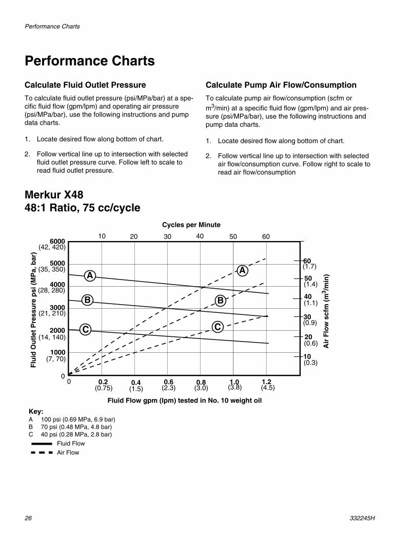
Calculate Fluid Outlet Pressure
To calculate fluid outlet pressure (psi/MPa/bar) at a spe-cific fluid flow (gpm/lpm) and operating air pressure(psi/MPa/bar), use the following instructions and pumpdata charts.
1. Locate desired flow along bottom of chart.
2. Follow vertical line up to intersection with selectedfluid outlet pressure curve. Follow left to scale toread fluid outlet pressure.
Calculate Pump Air Flow/Consumption
To calculate pump air flow/consumption (scfm or
m3/min) at a specific fluid flow (gpm/lpm) and air pres-sure (psi/MPa/bar), use the following instructions andpump data charts.
1. Locate desired flow along bottom of chart.
2. Follow vertical line up to intersection with selectedair flow/consumption curve. Follow right to scale toread air flow/consumption
Merkur X4848:1 Ratio, 75 cc/cycle
Cycles per Minute
00
Fluid Flow gpm (lpm) tested in No. 10 weight oil
Flu
idO
utl
etP
ress
ure
psi
(MP
a,b
ar)
Air
Flo
wsc
fm(m
3 /m
in)
0.2(0.75)
0.4 0.6 0.8 1.0(1.5) (2.3) (3.0) (3.8)
1.2(4.5)
10 20 30 40 50 60
1000(7, 70)
3000
4000
5000
6000
(14, 140)
(21, 210)
(28, 280)
(35, 350)
(42, 420)
2000
10
20
30
40
50
60
(0.3)
(0.6)
(0.9)
(1.1)
(1.4)
(1.7)A
B
C
A
B
C
Key:A 100 psi (0.69 MPa, 6.9 bar)B 70 psi (0.48 MPa, 4.8 bar)C 40 psi (0.28 MPa, 2.8 bar)
Fluid Flow
Air Flow
Performance Charts
332245H 27
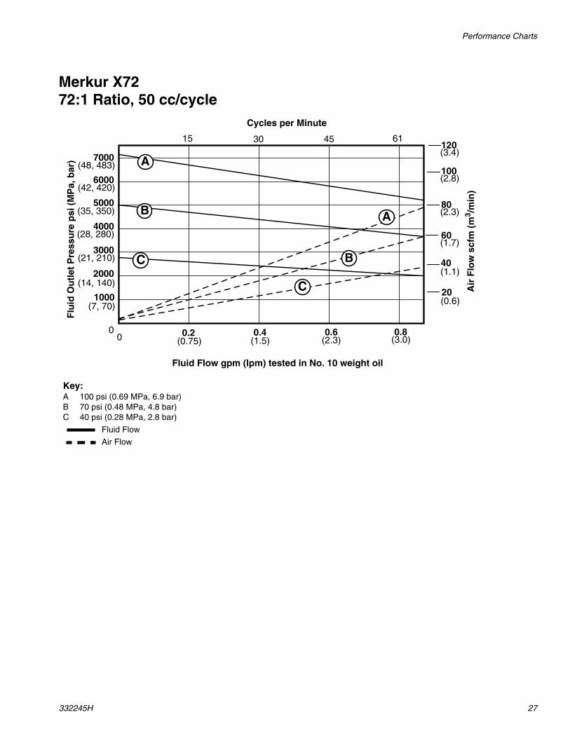
Merkur X7272:1 Ratio, 50 cc/cycle
Cycles per Minute
00
Fluid Flow gpm (lpm) tested in No. 10 weight oil
Flu
idO
utl
etP
ress
ure
psi
(MP
a,b
ar)
Air
Flo
wsc
fm(m
3 /m
in)
0.2(0.75)
0.4 0.6 0.8(1.5) (2.3) (3.0)
15 30 45 61
1000(7, 70)
3000
4000
5000
6000
(14, 140)
(21, 210)
(28, 280)
(35, 350)
(42, 420)
2000
20
40
60
(0.6)
(1.1)
(1.7)
80(2.3)
100(2.8)
120(3.4)7000
(48, 483) A
B
C
A
B
C
Key:A 100 psi (0.69 MPa, 6.9 bar)B 70 psi (0.48 MPa, 4.8 bar)C 40 psi (0.28 MPa, 2.8 bar)
Fluid Flow
Air Flow
Dimensions
28 332245H
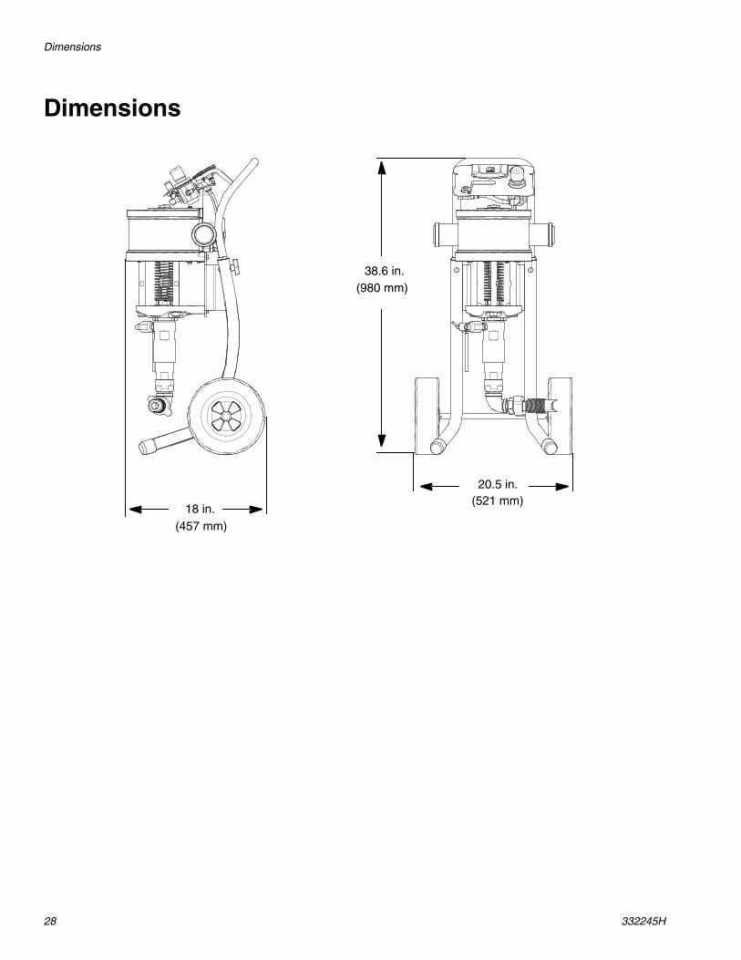
Dimensions
38.6 in.
18 in.
20.5 in.
(457 mm)
(521 mm)
(980 mm)
Technical Data
332245H 29
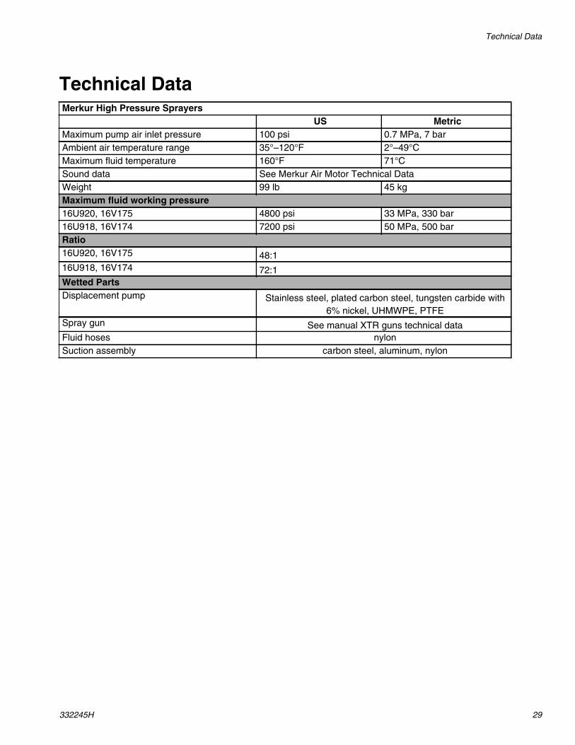
Technical DataMerkur High Pressure Sprayers
US MetricMaximum pump air inlet pressure 100 psi 0.7 MPa, 7 barAmbient air temperature range 35°–120°F 2°–49°CMaximum fluid temperature 160°F 71°CSound data See Merkur Air Motor Technical DataWeight 99 lb 45 kgMaximum fluid working pressure16U920, 16V175 4800 psi 33 MPa, 330 bar16U918, 16V174 7200 psi 50 MPa, 500 barRatio16U920, 16V175 48:116U918, 16V174 72:1Wetted PartsDisplacement pump Stainless steel, plated carbon steel, tungsten carbide with
6% nickel, UHMWPE, PTFESpray gun See manual XTR guns technical dataFluid hoses nylonSuction assembly carbon steel, aluminum, nylon

All written and visual data contained in this document reflects the latest product information available at the time of publication.Graco reserves the right to make changes at any time without notice.
This manual contains English. MM 332245
Graco Headquarters: MinneapolisInternational Offices: Belgium, China, Japan, Korea
GRACO INC. AND SUBSIDIARIES • P.O. BOX 1441 • MINNEAPOLIS MN 55440-1441 • USA
Copyright 2013, Graco Inc. All Graco manufacturing locations are registered to ISO 9001.www.graco.com
Revision H, January 2019
Graco Standard WarrantyGraco warrants all equipment referenced in this document which is manufactured by Graco and bearing its name to be free from defects inmaterial and workmanship on the date of sale to the original purchaser for use. With the exception of any special, extended, or limited warrantypublished by Graco, Graco will, for a period of twelve months from the date of sale, repair or replace any part of the equipment determined byGraco to be defective. This warranty applies only when the equipment is installed, operated and maintained in accordance with Graco’s writtenrecommendations.
This warranty does not cover, and Graco shall not be liable for general wear and tear, or any malfunction, damage or wear caused by faultyinstallation, misapplication, abrasion, corrosion, inadequate or improper maintenance, negligence, accident, tampering, or substitution ofnon-Graco component parts. Nor shall Graco be liable for malfunction, damage or wear caused by the incompatibility of Graco equipment withstructures, accessories, equipment or materials not supplied by Graco, or the improper design, manufacture, installation, operation ormaintenance of structures, accessories, equipment or materials not supplied by Graco.
This warranty is conditioned upon the prepaid return of the equipment claimed to be defective to an authorized Graco distributor for verification ofthe claimed defect. If the claimed defect is verified, Graco will repair or replace free of charge any defective parts. The equipment will be returnedto the original purchaser transportation prepaid. If inspection of the equipment does not disclose any defect in material or workmanship, repairswill be made at a reasonable charge, which charges may include the costs of parts, labor, and transportation.
THIS WARRANTY IS EXCLUSIVE, AND IS IN LIEU OF ANY OTHER WARRANTIES, EXPRESS OR IMPLIED, INCLUDING BUT NOTLIMITED TO WARRANTY OF MERCHANTABILITY OR WARRANTY OF FITNESS FOR A PARTICULAR PURPOSE.
Graco’s sole obligation and buyer’s sole remedy for any breach of warranty shall be as set forth above. The buyer agrees that no other remedy(including, but not limited to, incidental or consequential damages for lost profits, lost sales, injury to person or property, or any other incidental orconsequential loss) shall be available. Any action for breach of warranty must be brought within two (2) years of the date of sale.
GRACO MAKES NO WARRANTY, AND DISCLAIMS ALL IMPLIED WARRANTIES OF MERCHANTABILITY AND FITNESS FOR APARTICULAR PURPOSE, IN CONNECTION WITH ACCESSORIES, EQUIPMENT, MATERIALS OR COMPONENTS SOLD BUT NOTMANUFACTURED BY GRACO. These items sold, but not manufactured by Graco (such as electric motors, switches, hose, etc.), are subject tothe warranty, if any, of their manufacturer. Graco will provide purchaser with reasonable assistance in making any claim for breach of thesewarranties.
In no event will Graco be liable for indirect, incidental, special or consequential damages resulting from Graco supplying equipment hereunder, orthe furnishing, performance, or use of any products or other goods sold hereto, whether due to a breach of contract, breach of warranty, thenegligence of Graco, or otherwise.
FOR GRACO CANADA CUSTOMERSThe Parties acknowledge that they have required that the present document, as well as all documents, notices and legal proceedings entered into,given or instituted pursuant hereto or relating directly or indirectly hereto, be drawn up in English. Les parties reconnaissent avoir convenu que larédaction du présente document sera en Anglais, ainsi que tous documents, avis et procédures judiciaires exécutés, donnés ou intentés, à la suitede ou en rapport, directement ou indirectement, avec les procédures concernées.
Graco Information
For the latest information about Graco products, visit www.graco.com.For patent information, see www.graco.com/patents.
TO PLACE AN ORDER, contact your Graco distributor or call to identify the nearest distributor.Phone: 612-623-6921 or Toll Free: 1-800-328-0211 Fax: 612-378-3505