Embed Size (px)
Citation preview

Introduction .................................... 2In brief ............................................ 6Keys, doors and windows ............ 19Seats, restraints ........................... 34Storage ........................................ 57Instruments and controls ............. 77Lighting ...................................... 107Climate control ........................... 116Driving and operating ................. 124Vehicle care ............................... 146Service and maintenance .......... 185Technical data ........................... 189Customer information ................ 202Index .......................................... 204
Contents

2 Introduction
Introduction

Introduction 3
Vehicle specific dataPlease enter your vehicle's data onthe previous page to keep it easilyaccessible. This information isavailable in the sections "Service andmaintenance" and "Technical data"as well as on the identification plate.
IntroductionYour vehicle is a designedcombination of advanced technology,safety, environmental friendlinessand economy.This Owner's Manual provides youwith all the necessary information toenable you to drive your vehiclesafely and efficiently.Make sure your passengers areaware of the possible risk of accidentand injury which may result fromimproper use of the vehicle.You must always comply with thespecific laws and regulations of thecountry that you are in. These lawsmay differ from the information in thisOwner's Manual.
When this Owner's Manual refers toa workshop visit, we recommend yourOpel Service Partner.All Opel Service Partners providefirst-class service at reasonableprices. Experienced mechanicstrained by Opel work according tospecific Opel instructions.The customer literature pack shouldalways be kept ready to hand in thevehicle.
Using this manual■ This manual describes all options
and features available for thismodel. Certain descriptions,including those for display andmenu functions, may not apply toyour vehicle due to model variant,country specifications, specialequipment or accessories.
■ The "In brief" section will give youan initial overview.
■ The table of contents at thebeginning of this manual and withineach section shows where theinformation is located.
■ The index will enable you to searchfor specific information.
■ This Owner's Manual depicts left-hand drive vehicles. Operation issimilar for right-hand drive vehicles.
■ The Owner's Manual uses thefactory engine designations. Thecorresponding sales designationscan be found in the section"Technical data".
■ Directional data, e.g. left or right, orfront or back, always relate to thedirection of travel.
■ The vehicle display screens maynot support your specific language.
■ Display messages and interiorlabelling are written in bold letters.
Danger, Warnings andCautions
9 Danger
Text marked 9 Danger providesinformation on risk of fatal injury.Disregarding this information mayendanger life.

4 Introduction
9 Warning
Text marked 9 Warning providesinformation on risk of accident orinjury. Disregarding thisinformation may lead to injury.
Caution
Text marked Caution providesinformation on possible damage tothe vehicle. Disregarding thisinformation may lead to vehicledamage.
SymbolsPage references are indicated with3. 3 means "see page".We wish you many hours ofpleasurable driving.Adam Opel GmbH

Introduction 5

6 In brief
In brief
Initial drive information
Vehicle unlocking
Press button c to unlock the doorsand load compartment. Open thedoors by pulling the handles. To openthe tailgate, push the touchpad switchunder the tailgate moulding.Radio remote control 3 19, Centrallocking system 3 21, Loadcompartment 3 25.
Seat adjustmentSeat positioning
Pull handle, slide seat, releasehandle.Seat position 3 35, Seat adjustment3 36.
9 Danger
Do not sit nearer than 25 cm fromthe steering wheel, to permit safeairbag deployment.

In brief 7
Seat backrests
Pull lever, adjust inclination andrelease lever. Allow the seat toengage audibly.Seat position 3 35, Seat adjustment3 36.
Seat height
Lever pumping motionup = seat higherdown = seat lower
Seat position 3 35, Seat adjustment3 36.
Seat inclination
Lever pumping motionup = front end higherdown = front end lower
Seat position 3 35, Seat adjustment3 36.

8 In brief
Head restraint adjustment
Press the button, adjust height andengage.To adjust horizontally, pull the headrestraint forwards. It engages inseveral positions. To return to itsrearmost position, pull fully forwardsand release.Head restraints 3 34.
Seat belt
Pull out the seat belt and engage inbelt buckle. The seat belt must not betwisted and must fit close against thebody. The backrest must not be tiltedback too far (maximum approx. 25°).To release belt, press red button onbelt buckle.Seat position 3 35, Seat belts3 43, Airbag system 3 47.
Mirror adjustmentInterior mirror
To reduce dazzle, adjust the lever onthe underside of the mirror housing.Interior mirror 3 29, Automatic anti-dazzle interior mirror 3 29.

In brief 9
Exterior mirrors
Select the relevant exterior mirror andadjust it.Convex exterior mirrors 3 28,Electric adjustment 3 28, Foldingexterior mirrors 3 28, Heatedexterior mirrors 3 29.
Steering wheel adjustment
Unlock the lever, adjust the steeringwheel, then engage the lever andensure it is fully locked.Do not adjust the steering wheelunless the vehicle is stationary andthe steering wheel lock has beenreleased.Airbag system 3 47, Ignitionpositions 3 125.

In brief 11
Instrument panel overview1 Light switch ........................ 107
Headlight rangeadjustment ......................... 108Front fog lights ................... 111Rear fog light ...................... 111Instrument illumination ....... 112
2 Side air vents ...................... 1213 Turn and lane-change
signals, headlight flash,low beam and high beam ... 111Exit lighting ......................... 114Parking lights ...................... 112Driver Information Center ...... 94
4 Cruise control ..................... 1365 Instruments .......................... 846 Horn ..................................... 78
Driver airbag ........................ 477 Driver Information Center ...... 948 Steering wheel controls ....... 779 Windscreen wiper,
windscreen washersystem, rear wiper, rearwasher system ..................... 79
10 Centre air vents .................. 121
11 Infotainment system ............. 1012 Sensor for electronic
climate control system ....... 11813 Info-Display ........................... 9614 Central locking system .......... 21
Hazard warning flashers .... 110Control indicator for airbagdeactivation .......................... 89
15 Traction Control system ..... 134Electronic Stability Control . 135Deflation detection system . 169Ultrasonic parking assist .... 137
16 Front passenger airbag ........ 4717 Glovebox .............................. 5718 Climate control system ........ 11619 Selector lever, manual
transmission ....................... 131Automatic transmission ...... 128
20 Electrical parking brake ...... 13321 Accelerator pedal ............... 12422 Ignition switch with
steering wheel lock ............ 12523 Brake pedal ........................ 13224 Clutch pedal ....................... 124
25 Steering wheeladjustment ........................... 77
26 Storage compartment ........... 57Fuse box ............................ 164
27 Bonnet release lever .......... 147

In brief 13
Exterior lighting
Turn light switchAuto = Automatic light control:
Headlights are switched onand off automatically
m = activation or deactivation ofthe automatic light control
7 = off8 = sidelights9 = headlights
Press light switch> = front fog lightsr = rear fog light
Lighting 3 107.
Headlight flash, high beam andlow beam
headlight flash = pull leverhigh beam = push leverlow beam = push or pull lever
Automatic light control 3 108, Highbeam 3 108, Headlight flash 3 108.
Turn and lane-change signals
lever up = right turn signallever down = left turn signal
Turn and lane-change signals3 111, Parking lights 3 112.

14 In brief
Hazard warning flashers
Operated with the ¨ button.Hazard warning flashers 3 110.
Horn
Press j.
Washer and wiper systemsWindscreen wiper
2 = fast1 = slowP = interval wiping or automatic
wiping with rain sensor§ = off
For a single wipe when thewindscreen wiper is off, press thelever down.Windscreen wiper 3 79, Wiperblade replacement 3 151.

In brief 15
Windscreen washer system
Pull lever.Windscreen washer system 3 79,Washer fluid 3 150.
Rear window wiper and washersystems
Press the rocker switch to activate therear window wiper:upper position = short intervallower position = long intervalmiddle position = off
Push lever.Washer fluid is sprayed on the rearwindow and the wiper wipes a fewtimes.Rear window wiper/washer 3 80.

16 In brief
Climate controlHeated rear window, heatedexterior mirrors
The heating is operated by pressingthe Ü button.Heated rear window 3 32.
Demisting and defrosting thewindows
Press button V.Set the temperature control to thehighest level.Cooling n on.Heated rear window Ü on.Climate control system 3 116.
TransmissionManual transmission
Reverse: with the vehicle stationary,depress the clutch pedal, press therelease button on the selector leverand engage the gear.If the gear does not engage, set thelever to neutral, release the clutchpedal and depress again; then repeatgear selection.Manual transmission 3 131.

In brief 17
Automatic transmission
P = parkR = reverseN = neutralD = drive
Manual mode: move selector leverfrom D to the left.< = higher gear] = lower gear
The selector lever can only be movedout of P when the ignition is on andthe brake pedal is applied. To engageP or R, press the release button.Automatic transmission 3 128.
Starting offCheck before starting off■ Tyre pressure and condition3 168, 3 198.
■ Engine oil level and fluid levels3 148.
■ All windows, mirrors, exteriorlighting and number plates are freefrom dirt, snow and ice and areoperational.
■ Proper position of mirrors, seats,and seat belts 3 28, 3 35,3 44.
■ Brake function at low speed,particularly if the brakes are wet.
Starting the engine
■ Turn key to position 1■ move the steering wheel slightly to
release the steering wheel lock■ operate clutch and brake■ automatic transmission in P or N■ do not operate accelerator pedal■ diesel engines: turn the key to
position 2 for preheating and waituntil control indicator ! goes out
■ turn key to position 3 and releaseStarting the engine 3 125.

18 In brief
Parking■ Always apply the parking brake.
Pull switch m.■ Switch off the engine. Turn the
ignition key to 0 and remove it. Turnthe steering wheel until the steeringwheel lock is felt to engage.For vehicles with automatictransmission, the key can only beremoved when the selector lever isin the P position.
■ If the vehicle is on a level surface oruphill slope, engage first gear or setthe selector lever to P beforeswitching off the ignition. On anuphill slope, turn the front wheelsaway from the kerb.If the vehicle is on a downhill slope,engage reverse gear or set theselector lever to P before switchingoff the ignition. Turn the frontwheels towards the kerb.
■ Lock the vehicle with button e onthe radio remote control.Activate the anti-theft alarm system3 27.
■ Do not park the vehicle on an easilyignitable surface. The hightemperature of the exhaust systemcould ignite the surface.
■ Close the windows.■ The engine cooling fans may run
after the engine has been switchedoff 3 147.
■ After running at high engine speedsor with high engine loads, operatethe engine briefly at a low load orrun in neutral for approx.30 seconds before switching off, inorder to protect the turbocharger.
Keys, locks 3 19, Laying the vehicleup for a long period of time 3 146.

Keys, doors and windows 19
Keys, doors andwindows
Keys, locks ................................... 19Doors ........................................... 25Vehicle security ............................ 26Exterior mirrors ............................ 28Interior mirrors ............................. 29Windows ...................................... 30Roof ............................................. 32
Keys, locksKeysReplacement keysThe key number is specified in theCar Pass or on a detachable tag.The key number must be quotedwhen ordering replacement keys as itis a component of the immobilisersystem.Locks 3 182.
Key with foldaway key section
Press button to extend. To fold thekey, first press the button.
Car PassThe Car Pass contains securityrelated vehicle data and shouldtherefore be kept in a safe place.When the vehicle is taken toa workshop, this vehicle data isneeded in order to perform certainoperations.
Radio remote control

20 Keys, doors and windows
Used to operate:■ Central locking system■ Anti-theft locking system■ Anti-theft alarm system■ Power windowsThe radio remote control has anapproximate range of up to 5 metres.It can be restricted by externalinfluences. The hazard warningflashers confirm operation.Handle with care, protect frommoisture and high temperatures andavoid unnecessary operation.
FaultIf the central locking system cannotbe operated with the radio remotecontrol, it may be due to the following:■ Range exceeded■ Battery voltage too low■ Frequent, repeated operation of the
radio remote control while not inrange, which will require re-synchronisation
■ Overload of the central lockingsystem by operating at frequentintervals, the power supply isinterrupted for a short time
■ Interference from higher-powerradio waves from other sources
Unlocking 3 21.
Basic settingsSome settings can be changed in themenu Settings in the Info-Display.Vehicle personalisation 3 102.
Radio remote control batteryreplacementReplace the battery as soon as therange reduces.
Batteries do not belong in householdwaste. They must be disposed of atan appropriate recycling collectionpoint.
Key with foldaway key section
Extend the key and open the unit.Replace the battery (battery typeCR 2032), paying attention to theinstallation position. Close the unitand synchronise.
Key with fixed key sectionHave the battery replaced bya workshop.

Keys, doors and windows 21
Radio remote controlsynchronisationAfter replacing the battery, unlock thedoor with the key in the driver's doorlock. The radio remote control will besynchronised when the ignition isswitched on.
Memorised settingsWhenever the key is removed fromthe ignition switch, the followingsettings are automatically memorisedby the key:■ Lighting■ Infotainment system (only CD 400 /
CDC 400)■ Central locking system■ Comfort settingsThe saved settings are automaticallyused the next time the memorised keyis inserted into the ignition switch andturned to position 3 3 125.Precondition is, that Personalizationby driver, or, depending on thedisplay type, Personalization by
remote control is activated in thepersonal settings of the Info-Display.This must be set for each key used.Vehicle personalisation 3 102.
Central locking systemUnlocks and locks doors, loadcompartment and fuel filler flap.A pull on an interior door handleunlocks the respective door. Pullingthe handle once more opens the door.NoteIn the event of an accident in whichairbags or belt pretensioners aredeployed, the vehicle isautomatically unlocked.NoteA short time after unlocking with theremote control the doors are lockedautomatically if no door has beenopened.
Unlocking
Press button c.Two settings are selectable:■ To unlock only the driver's door and
the fuel filler flap, press button conce. To unlock all doors and theload compartment, press button ctwice,or
■ press button c once to unlock alldoors, load compartment and fuelfiller flap.

22 Keys, doors and windows
The setting can be changed in themenu Settings in the Info-Display.Vehicle personalisation 3 102.The setting can be saved for the keybeing used.Memorised settings 3 21.
LockingClose doors, load compartment andfuel filler flap.
Press button e.If the driver's door is not closedproperly, the central locking systemwill not work.
Unlocking and opening thetailgate
Press button c when the ignition is offto unlock all doors. The tailgate isreleased and is unlocked and openedby pushing the touchpad switch underthe tailgate moulding.
Central locking buttonLocks or unlocks all doors, the loadcompartment and fuel filler flap fromthe passenger compartment.
Press central locking button: thedoors are locked or unlocked. If thedoors are locked the LED in thebutton illuminates.After locking with the radio remotecontrol the LED in the buttonilluminates for approx. 2 minutes.

Keys, doors and windows 23
Fault in radio remote controlsystem
Unlocking
Manually unlock the driver's door byturning the key in the lock. Switch onthe ignition and press the centrallocking button to unlock all doors,load compartment and fuel filler flap.By switching on the ignition, the anti-theft locking system is deactivated3 27.
LockingClose the driver's door, open thepassenger door, press central lockingbutton. The vehicle is locked. Closethe passenger door.
Fault in central locking system
UnlockingManually unlock the driver's door byturning the key in the lock. The otherdoors can be opened by pulling theinterior handle twice. The loadcompartment and fuel filler flapcannot be opened. To deactivate theanti-theft locking system, switch onthe ignition 3 27.
Locking
Insert key into the opening above thelock on inside of the door and operatethe lock by pressing until it clicks.Then close the door. The proceduremust be carried out for each door. Thedriver's door can also be locked fromthe outside with the key. The fuel fillerflap and the tailgate cannot be locked.

24 Keys, doors and windows
Automatic lockingAutomatic locking after drivingoffThe vehicle is locked automaticallywhen exceeding a speed of 4 km/h.Opening from outside is not possible.Additionally, opening of the reardoors from inside is not possiblewhen the vehicle speed is above4 km/h.
Green LEDs indicate that openingfrom inside is possible:
Grasp the inner rear door handle toactivate the proximity sensor and pullthe handle.When the vehicle speed is below4 km/h, opening of the doors fromoutside is possible after:■ opening any door from inside■ pressing the central locking buttonc
Caution
Automatic locking is only activewith ignition on.
Fault in the automatic locking systemIn case of a system fault ^illuminates in the instrument clusterand a warning chime sounds toindicate that the rear doors are notsecured against opening. Informpassengers to keep clear of the doorhandles.Stop immediately and activate thechild lock in both rear doors. If thechild lock is already activated, firstdeactivate and then activate again.The green LEDs will go out and the
warning chime will stop as soon asboth child locks are activated. Pull theinner rear door handles to check if thedoors are locked from inside. Consulta workshop.
Child locks
9 Warning
Use the child locks wheneverchildren are occupying the rearseats.

Keys, doors and windows 25
Using a key or suitable screwdriver,turn the child lock in the rear door tothe horizontal position. The greenLED will go out. The door cannot beopened from the inside. Fordeactivation turn the child lock to thevertical position.
DoorsRear doors
9 Warning
Take care of other persons whengetting in or out at the front andrear simultaneously.Only use the grab handleprovided.
The rear doors have an automaticlocking feature 3 24.
Load compartmentTailgate
Opening
After unlocking push the touchpadswitch under the tailgate mouldingand open the tailgate.Central locking system 3 21.

26 Keys, doors and windows
Closing
Use one of the interior handles.Do not push the touchpad switchunder the moulding whilst closing asthis will unlock the tailgate again.Central locking system 3 21.
General hints for operatingtailgate
9 Warning
Do not drive with the tailgate openor ajar, e.g. when transportingbulky objects, since toxic exhaustgases, which can not be seen orsmelled, could enter the vehicle.This can cause unconsciousnessand even death.
Caution
Before opening the tailgate checkoverhead obstructions, such asa garage door, to avoid damage tothe tailgate. Always check themoving area above and behind thetailgate.
NoteThe installation of certain heavyaccessories onto the tailgate mayaffect its ability to remain open.
Vehicle securityAnti-theft locking system
9 Warning
Do not use the system if there arepeople in the vehicle! The doorscannot be unlocked from theinside.
The system deadlocks all the doors.All doors must be closed otherwisethe system cannot be activated.If the ignition was on, the driver's doormust be opened and closed once sothat the vehicle can be secured.Unlocking the vehicle disables themechanical anti-theft locking system.This is not possible with the centrallocking button.

Keys, doors and windows 27
Activating
Press e on the radio remote controltwice within 10 seconds.
Anti-theft alarm systemThe anti-theft alarm systemincorporates and is operated inconjunction with the anti-theft lockingsystem.It monitors:■ Doors, tailgate, bonnet■ IgnitionUnlocking the vehicle deactivatesboth systems simultaneously.
Status LED
Status LED is integrated in the centrallocking button.Status during the first 10 seconds ofanti-theft alarm system activation:LEDilluminates
= test, arming delay.
LED flashesquickly
= doors, tailgate orbonnet notcompletely closed,or system fault.
Status after system is armed:LED flashesslowly
= system is armed.
Seek the assistance of a workshop inthe event of faults.
AlarmWhen triggered, the horn sounds, andthe hazard warning lights flashsimultaneously. The number andduration of alarm signals arestipulated by legislation.The alarm can be silenced bypressing any button of the radioremote control or by switching on theignition.The anti-theft alarm system can bedeactivated only by pressing buttonc or by switching on the ignition.
ImmobiliserThe system is part of the ignitionswitch and checks whether thevehicle is allowed to be started withthe key being used.The immobiliser is activatedautomatically after the key has beenremoved from the ignition switch.

28 Keys, doors and windows
If the control indicator d flashes whenthe ignition is on, there is a fault in thesystem; the engine cannot be started.Switch off the ignition and then repeatthe start attempt.If the control indicator continuesflashing, attempt to start the engineusing the spare key and seek theassistance of a workshop.NoteThe immobiliser does not lock thedoors. You should always lock thevehicle after leaving it and switch onthe anti-theft alarm system 3 21,3 27.
Control indicator d 3 92.
Exterior mirrorsConvex shapeThe convex exterior mirror reducesblind spots. The shape of the mirrormakes objects appear smaller, whichwill affect the ability to estimatedistances.
Electric adjustment
Select the relevant exterior mirror byturning the control to left (L) or right(R). Then swivel the control to adjustthe mirror.
In position 0 no mirror is selected.
Folding
For pedestrian safety, the exteriormirrors will swing out of their normalmounting position if they are struckwith sufficient force. Reposition themirror by applying slight pressure tothe mirror housing.
Keys, doors and windows 29
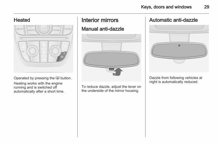
Heated
Operated by pressing the Ü button.Heating works with the enginerunning and is switched offautomatically after a short time.
Interior mirrorsManual anti-dazzle
To reduce dazzle, adjust the lever onthe underside of the mirror housing.
Automatic anti-dazzle
Dazzle from following vehicles atnight is automatically reduced.

30 Keys, doors and windows
WindowsManual windowsThe door windows can be opened orclosed with the window winders.
Power windows
9 Warning
Take care when operating thepower windows. Risk of injury,particularly to children.If there are children on the rearseats, switch on the child safetysystem for the power windows.Keep a close watch on thewindows when closing them.Ensure that nothing becomestrapped in them as they move.
Power windows can be operated:■ with ignition on■ within 10 minutes of switching
ignition off■ within 5 minutes of opening or
closing a doorAfter switching off the ignition,window operation is disabled as soonas the vehicle is locked with the radioremote control.
Operate the switch for the respectivewindow by pushing to open or pullingto close.
Pushing or pulling gently to the firstdetent: window moves up or down aslong as switch is operated.Pushing or pulling firmly to the seconddetent and then releasing: windowmoves up or down automatically withsafety function enabled. To stopmovement, operate the switch oncemore in the same direction.
Safety functionIf the window glass encountersresistance above the middle of thewindow during automatic closing, it isimmediately stopped and openedagain.
Override safety functionIn the event of closing difficulties dueto frost or the like, pull and hold theswitch. The window moves up withoutsafety function enabled. To stopmovement, release and pull theswitch once more.

Keys, doors and windows 31
Child safety system for rearwindows
Press switch z to deactivate reardoor power windows, the LEDilluminates. To activate, press zagain.
Operating windows from outsideThe windows can be operatedremotely from outside the vehicle.
Press and hold c button to openwindows.Press and hold e button to closewindows.Release button to stop windowmovement.
OverloadIf the windows are repeatedlyoperated within short intervals, thewindow operation is disabled forsome time.
Initialising the power windowsIf the windows cannot be closedautomatically (e.g. afterdisconnecting the vehicle battery),a warning message or a warning codeis displayed in the Driver InformationCenter.Vehicle messages 3 98.Activate the window electronics asfollows:1. Close doors.2. Switch on ignition.3. Pull switch until the window is
closed and keep pulling foradditional 2 seconds.
4. Repeat for each window.
32 Keys, doors and windows
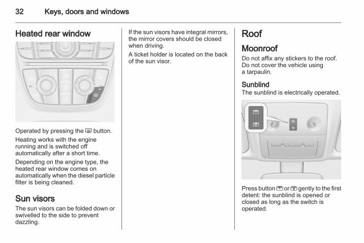
Heated rear window
Operated by pressing the Ü button.Heating works with the enginerunning and is switched offautomatically after a short time.Depending on the engine type, theheated rear window comes onautomatically when the diesel particlefilter is being cleaned.
Sun visorsThe sun visors can be folded down orswivelled to the side to preventdazzling.
If the sun visors have integral mirrors,the mirror covers should be closedwhen driving.A ticket holder is located on the backof the sun visor.
RoofMoonroofDo not affix any stickers to the roof.Do not cover the vehicle usinga tarpaulin.
SunblindThe sunblind is electrically operated.
Press button G or H gently to the firstdetent: the sunblind is opened orclosed as long as the switch isoperated.

Keys, doors and windows 33
Press button G or H firmly to thesecond detent and then release: thesunblind is opened or closedautomatically. To stop movement,operate the switch once more.
Safety functionIf the sunblind encounters resistanceduring automatic closing, it isimmediately stopped and openedagain.
Function standbyIn ignition switch position 1 thesunblind is operable 3 125.
Initialising of the sunblindIf the sunblind cannot be operated(e.g. after disconnecting the vehiclebattery), activate the electronics asfollows:■ If sunblind is closed, keep the
switch H pressed gently to the firstdetent for 10 seconds.
■ If sunblind is open, keep the switchH pressed until sunblind is fullyclosed. Then release switch brieflyand press it again gently to the firstdetent for 10 seconds.
Relearning of safety functionIf the sunblind does not operatecorrectly after initialising:1. Open sunblind fully by pressing
switch G.2. Release switch and then press
switch G again gently to the firstdetent for approx. 30 seconds.Then close sunblind by pressingswitch H until the sunblind isclosed.

34 Seats, restraints
Seats, restraints
Head restraints ............................ 34Front seats ................................... 35Rear seats ................................... 40Seat belts ..................................... 43Airbag system .............................. 47Child restraints ............................. 51
Head restraints
Position
9 Warning
Only drive with the head restraintset to the proper position.
The upper edge of the head restraintshould be at upper head level. If thisis not possible for extremely tallpeople, set to highest position, andset to lowest position for small people.
Adjustment
Head restraints on front seats
Height adjustmentPress the button, adjust height andengage.

Seats, restraints 35
Horizontal adjustmentTo adjust horizontally, pull the headrestraint forwards. It engages inseveral positions.To return to its rearmost position, pullfully forwards and release.
Active head restraints on front seatsIn the event of a rear-end impact, thefront parts of the active headrestraints are moved slightlyforwards. Thus the head is supportedso that the risk of whiplash injury isreduced.
NoteApproved accessories may only beattached, if the seat is not in use.
Head restraints on rear seats
Height adjustmentPull the head restraint upwards orpress both catches to release andpush the head restraint downwards.
Front seatsSeat position
9 Warning
Only drive with the seat correctlyadjusted.
■ Sit with buttocks as far back againstthe backrest as possible. Adjust thedistance between the seat and thepedals so that legs are slightlyangled when pressing the pedals.Slide the front passenger seat asfar back as possible.

36 Seats, restraints
■ Sit with shoulders as far backagainst the backrest as possible.Set the backrest rake so that it ispossible to easily reach thesteering wheel with arms slightlybent. Maintain contact betweenshoulders and the backrest whenturning the steering wheel. Do notangle the backrest too far back. Werecommend a maximum rake ofapprox. 25°.
■ Adjust the steering wheel 3 77.■ Set seat height high enough to
have a clear field of vision on allsides and of all display instruments.There should be at least one handof clearance between head and theroof frame. Your thighs should restlightly on the seat without pressinginto it.
■ Adjust the head restraint 3 34.■ Adjust the height of the seat belt3 44.
■ Adjust the thigh support so thatthere is a space approx. two fingerswide between the edge of the seatand the hollow of the knee.
■ Adjust the lumbar support so that itsupports the natural shape of thespine.
Seat adjustment
9 Danger
Do not sit nearer than 25 cm fromthe steering wheel, to permit safeairbag deployment.
9 Warning
Never adjust seats while driving asthey could move uncontrollably.
Seat positioning
Pull handle, slide seat, releasehandle.

Seats, restraints 37
Seat backrests
Pull lever, adjust inclination andrelease lever. Allow the backrest toengage audibly.
Seat height
Lever pumping motionup = seat higherdown = seat lower
Seat inclination
Lever pumping motionup = front end higherdown = front end lower

38 Seats, restraints
Lumbar support
Adjust lumbar support using the four-way switch to suit personalrequirements.Moving support up and down: pushswitch up or down.Increasing and decreasing support:push switch forwards or backwards.
Adjustable thigh support
Pull the lever and slide the thighsupport.
ArmrestDetachable armrest
The armrest contains a storagecompartment.Storage compartment 3 60.

Seats, restraints 39
Installing armrest
Press the rear button and insert therear guide pins into the upper guiderails. Release the button.
Lower the armrest at the front. Pull thefront handle firmly and insert the frontguide pins into the upper guide rails.Release the handle. Move thearmrest until it engages audibly.NoteInstall the armrest in the direction asshown in the graphic. Otherwise thearmrest may not engage properly.
Moving armrest
Pull the front handle slightly and movethe armrest to the desired position.Release the handle. Move thearmrest until it engages audibly.If a cupholder is installed in the lowerguide rail, make sure that the frame ofthe cupholder is in the initial position.NoteIf too much weight is put on thearmrest, it might unlatch. Ease ofmovement might be restricted. Liftthe armrest slightly to latch again.
Armrest storage 3 60.Cupholders 3 57.

40 Seats, restraints
Removing armrestPull the front handle firmly and raisethe armrest at the front. Press the rearbutton and remove the armrest.The armrest can also be installed onthe folded centre rear seat 3 42.
Heating
Adjust heating to the desired settingby pressing the ß button for therespective seat one or more timeswith the ignition on. The controlindicator in the button indicates thesetting.
Prolonged use of the highest settingfor people with sensitive skin is notrecommended.Seat heating is operational whenengine is running.
Rear seats
Seat adjustment
9 Warning
Only drive with the outer seatsengaged in the guide rails.
9 Warning
Never adjust seats while driving asthey could move uncontrollably.

Seats, restraints 41
The rear outboard seats can beindividually moved forward orbackward. The seats are movable inlongitudinal and transversal direction.In longitudinal direction the seats canbe engaged in intermediate positions.Pull handle, slide seat, releasehandle and allow seat to engage.
Flexible Seat System(FlexSpace)
The rear seat row can be adjustedwith two seats providing maximumseating space in position 1, or withthree seats in position 2. In position1 the centre seat is lowered.The outboard seats can be movedforward into position 3.
Moving seats to position 1
Pull the strap and fold down thecentre seat.
Pull handle and slide the seattransversely backward into position1. The seat is automatically guidedinward. Release handle and allowseat to engage in position.

42 Seats, restraints
Moving seats to position 2
Pull handle and slide the seattransversely forwards into position 2.The seat is automatically guidedoutward. Release handle and allowseat to engage in position.
9 Warning
Detach the armrest before raisingthe rear centre backrest.Armrest 3 38.
Pull the strap and raise the centreseat.The centre seat is not usable if theouter seats are moved forward inposition 3.
ArmrestAn armrest adapter can be installedon the seatback of the centre seat.A detachable armrest or a cupholdercan be attached to the adapter.
Installing the adapterPull the strap and fold down thecentre seat 3 40.
Insert the hooks of the adapter intothe recesses of the seatback andpush the adapter forwards.

Seats, restraints 43
Lock the adapter by turning theignition key clockwise in the lock. Theadapter is locked properly when thegreen mark is visible.Mount the armrest or the cupholderon the adapter.Armrest 3 38, Cupholder 3 57.
Removing the adapterDetach the armrest or the cupholderfrom the adapter.Armrest 3 38, Cupholder 3 57.Unlock the adapter by turning theignition key anticlockwise in the lock.The adapter is unlocked when the redmark is visible.Push the adapter rearward andremove.
Seat belts
The seat belts are locked duringheavy acceleration or deceleration ofthe vehicle holding the occupants inthe sitting position. Thereby the risk ofinjury is considerably reduced.
9 Warning
Fasten seat belt before each trip.In the event of an accident, peoplenot wearing seat belts endangertheir fellow occupants andthemselves.
Seat belts are designed to be used byonly one person at a time. They arenot suitable for people smaller than150 cm. Child restraint system3 51.Periodically check all parts of the beltsystem for damage and properfunctionality.Have damaged componentsreplaced. After an accident, have thebelts and triggered belt pretensionersreplaced by a workshop.NoteMake sure that the belts are notdamaged by shoes or sharp-edgedobjects or trapped. Prevent dirt fromgetting into the belt retractors.
Seat belt reminder X 3 88.
Belt force limitersStress on the body is reduced by thegradual release of the belt duringa collision.
Belt pretensionersIn the event of a head-on or rear-endcollision of a certain severity, the frontseat belts are tightened.

44 Seats, restraints
9 Warning
Incorrect handling (e.g. removal orfitting of belts) can trigger the beltpretensioners.
Deployment of the belt pretensionersis indicated by continuous illuminationof control indicator v 3 88.Triggered belt pretensioners must bereplaced by a workshop. Beltpretensioners can only be triggeredonce.NoteDo not affix or install accessories orother objects that may interfere withthe operation of the beltpretensioners. Do not make anymodifications to belt pretensionercomponents as this will invalidatethe vehicle type approval.
Three-point seat beltFastening seat belt
Withdraw the belt from the retractor,guide it untwisted across the bodyand insert the latch plate into thebuckle. Tighten the lap belt regularlywhilst driving by pulling the shoulderbelt.Seat belt reminder 3 88.
Loose or bulky clothing prevents thebelt from fitting snugly. Do not placeobjects such as handbags or mobilephones between the belt and yourbody.
9 Warning
The belt must not rest against hardor fragile objects in the pockets ofyour clothing.
Seats, restraints 45
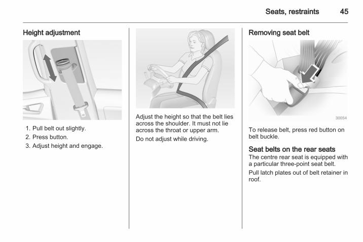
Height adjustment
1. Pull belt out slightly.2. Press button.3. Adjust height and engage.
Adjust the height so that the belt liesacross the shoulder. It must not lieacross the throat or upper arm.Do not adjust while driving.
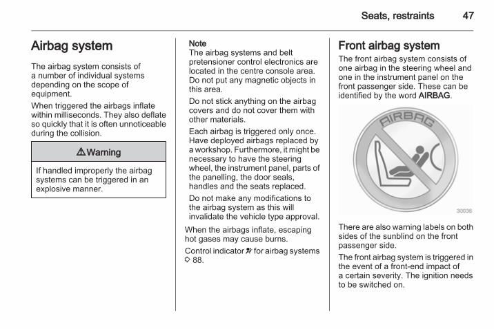
Removing seat belt
To release belt, press red button onbelt buckle.
Seat belts on the rear seatsThe centre rear seat is equipped witha particular three-point seat belt.Pull latch plates out of belt retainer inroof.

46 Seats, restraints
Click bottom latch plate into right-hand buckle (1) at centre seat.Remove top latch plate from retainer,guide over shoulder and lap area withbelt (do not twist) and click into left-hand buckle (2) at centre seat.To remove the seat belt, first pressthe button on the left-hand buckle (2)and remove top latch plate. Thenpress the button on the right-handbuckle (1) and remove bottom latchplate. The seat belt retractsautomatically.
Push the top latch plate into theretainer. Fold over locked togetherlatch plates against the seat belt.
Insert in the seat belt holder in the roofwith the lower latch plate pointingforward.
Using the seat belt whilepregnant
9 Warning
The lap belt must be positioned aslow as possible across the pelvisto prevent pressure on theabdomen.
Seats, restraints 47
Airbag systemThe airbag system consists ofa number of individual systemsdepending on the scope ofequipment.When triggered the airbags inflatewithin milliseconds. They also deflateso quickly that it is often unnoticeableduring the collision.
9 Warning
If handled improperly the airbagsystems can be triggered in anexplosive manner.
NoteThe airbag systems and beltpretensioner control electronics arelocated in the centre console area.Do not put any magnetic objects inthis area.Do not stick anything on the airbagcovers and do not cover them withother materials.Each airbag is triggered only once.Have deployed airbags replaced bya workshop. Furthermore, it might benecessary to have the steeringwheel, the instrument panel, parts ofthe panelling, the door seals,handles and the seats replaced.Do not make any modifications tothe airbag system as this willinvalidate the vehicle type approval.
When the airbags inflate, escapinghot gases may cause burns.Control indicator v for airbag systems3 88.
Front airbag systemThe front airbag system consists ofone airbag in the steering wheel andone in the instrument panel on thefront passenger side. These can beidentified by the word AIRBAG.
There are also warning labels on bothsides of the sunblind on the frontpassenger side.The front airbag system is triggered inthe event of a front-end impact ofa certain severity. The ignition needsto be switched on.

48 Seats, restraints
The inflated airbags cushion theimpact, thereby reducing the risk ofinjury to the upper body and head ofthe front seat occupantsconsiderably.
9 Warning
Optimum protection is onlyprovided when the seat is in theproper position 3 35.Keep the area in which the airbaginflates clear of obstructions.Fit the seat belt correctly andengage securely. Only then theairbag is able to protect.
Side airbag system
The side airbag system consists of anairbag in each front seat backrest.This can be identified by the wordAIRBAG.The side airbag system is triggered inthe event of a side impact of a certainseverity. The ignition needs to beswitched on.
The inflated airbags cushion theimpact, thereby reducing the risk ofinjury to the upper body and pelvis inthe event of a side-on collisionconsiderably.

Seats, restraints 49
9 Warning
Keep the area in which the airbaginflates clear of obstructions.
NoteOnly use protective seat covers thathave been approved for the vehicle.Be careful not to cover the airbags.
Curtain airbag systemThe curtain airbag system consists ofan airbag in the roof frame on eachside. This can be identified by theword AIRBAG on the roof pillars.The curtain airbag system is triggeredin the event of a side-on impact ofa certain severity. The ignition needsto be switched on.
The inflated airbags cushion theimpact, thereby reducing the risk ofinjury to the head in the event ofa side-on impact considerably.
9 Warning
Keep the area in which the airbaginflates clear of obstructions.The hooks in the roof frame areonly suitable for hanging up lightarticles of clothing, without coathangers. Do not keep any items inthese clothes.
Airbag deactivationThe front passenger airbag systemhas to be deactivated if a childrestraint system is to be fitted on thisseat. The side airbag and curtainairbag systems, the beltpretensioners and all driver airbagsystems will remain active.
The front passenger airbag systemcan be deactivated via a key-operated switch on the right side ofthe instrument panel.

50 Seats, restraints
Use the ignition key to choose theposition:* = front passenger airbag is
deactivated and will not inflatein the event of a collision.Control indicator * illuminatescontinuously in the centreconsole. A child restraintsystem can be installed inaccordance with thechart Child restraintinstallation locations 3 53.No adult person is allowed tooccupy the front passengerseat.
V = front passenger airbag isactive. A child restraint systemmust not be installed.
9 Danger
Risk of fatal injury for a child usinga child restraint system on a seatwith activated front passengerairbag.Risk of fatal injury for an adultperson on a seat with deactivatedfront passenger airbag.
As long as the control indicator V isilluminated, the front passengerairbag system will inflate in the eventof a collision.If both control indicators areilluminated at the same time, there isa system failure. The status of thesystem is not discernible, thereforeno person is allowed to occupy thefront passenger seat. Contacta workshop immediately.Consult a workshop immediately ifneither of the two control indicators isilluminated.Change status only when the vehicleis stopped with the ignition off.
Status remains until the next change.Control indicator for airbagdeactivation 3 89.

Seats, restraints 51
Child restraintsChild restraint systemsWe recommend the Opel childrestraint system which is tailoredspecifically to the vehicle.When a child restraint system is beingused, pay attention to the followingusage and installation instructionsand also those supplied with the childrestraint system.Always comply with local or nationalregulations. In some countries, theuse of child restraint systems isforbidden on certain seats.
9 Warning
When using a child restraintsystem on the front passengerseat, the airbag systems for thefront passenger seat must bedeactivated; if not, the triggering ofthe airbags poses a risk of fatalinjury to the child.This is especially the case if rear-facing child restraint systems areused on the front passenger seat.
Selecting the right systemThe rear seats are the mostconvenient location to fasten a childrestraint system.Children should travel facingrearwards in the vehicle as long aspossible. This makes sure that thechild's backbone, which is still veryweak, is under less strain in the eventof an accident.Children under the age of 12 yearsthat are smaller than 150 cm are onlyallowed to travel in a restraint systemthat is suitable for the child. Suitable
are restraint systems that comply withECE 44-03 or ECE 44-04. Sincea proper position of the belt is rarelypossible with a child that is smallerthan 150 cm, we strongly advise theuse of an appropriate child restraintsystem, even though this might, dueto the age of the child, no longer belegally binding.Ensure that the child restraint systemto be installed is compatible with thevehicle type.Ensure that the mounting location ofthe child restraint system within thevehicle is correct.Allow children to enter and exit thevehicle only on the side facing awayfrom the traffic.When the child restraint system is notin use, secure the seat with a seat beltor remove it from the vehicle.

52 Seats, restraints
NoteDo not stick anything on the childrestraint systems and do not coverthem with any other materials.A child restraint system which hasbeen subjected to stress in anaccident must be replaced.

Seats, restraints 53
Child restraint installation locationsPermissible options for fitting a child restraint system
Weight and age classOn front passenger seat
On rear outboard seats On rear centre seatactivated airbag deactivated airbag
Group 0: up to 10 kgor approx. 10 months
X U1 U2, 4 U3
Group 0+: up to 13 kgor approx. 2 years
X U1 U2, 4 U3
Group I: 9 to 18 kgor approx. 8 months to 4 years
X U1 U2, 4 U3
Group II: 15 to 25 kgor approx. 3 to 7 years
X X U4 U3
Group III: 22 to 36 kgor approx. 6 to 12 years
X X U4 U3

54 Seats, restraints
1 = Only if front passenger seat airbag system is deactivated. If the child restraint system is being secured using a three-point seat belt, move seat height adjustment to uppermost position and ensure that vehicle seat belt runs forwardsfrom the upper anchorage point.
2 = Seat available with ISOFIX and Top-Tether mounting brackets.3 = Only if outboard seats are flush with the centre seat (position 2, 3 40).4 = Only if outboard seats are in position 1 or 2, 3 40.U = Universal suitability in conjunction with three-point seat belt.X = No child restraint system permitted in this weight and age class.
Permissible options for fitting an ISOFIX child restraint systemWeight class Size class Fixture On front passenger seat On rear outboard seats On rear centre seat
Group 0: up to 10 kg E ISO/R1 X IL X
Group 0+: up to 13 kg E ISO/R1 X IL X
D ISO/R2 X IL X
C ISO/R3 X IL X
Group I: 9 to 18 kg D ISO/R2 X IL X
C ISO/R3 X IL X
B ISO/F2 X IL, IUF X
B1 ISO/F2X X IL, IUF X
A ISO/F3 X IL, IUF X

Seats, restraints 55
IL = Suitable for particular ISOFIX restraint systems of the 'specific-vehicle', 'restricted' or 'semi-universal' categories.The ISOFIX restraint system must be approved for the specific vehicle type.
IUF = Suitable for ISOFIX forward-facing child restraint systems of universal category approved for use in this weightclass.
X = No ISOFIX child restraint system approved in this weight class.
ISOFIX size class and seat deviceA – ISO/F3 = Forward-facing child restraint system for children of maximum size in the weight class 9 to 18 kg.B – ISO/F2 = Forward-facing child restraint system for smaller children in the weight class 9 to 18 kg.B1 – ISO/F2X = Forward-facing child restraint system for smaller children in the weight class 9 to 18 kg.C – ISO/R3 = Rear-facing child restraint system for children of maximum size in the weight class up to 13 kg.D – ISO/R2 = Rear-facing child restraint system for smaller children in the weight class up to 13 kg.E – ISO/R1 = Rear-facing child restraint system for young children in the weight class up to 13 kg.
56 Seats, restraints
ISOFIX child restraintsystems
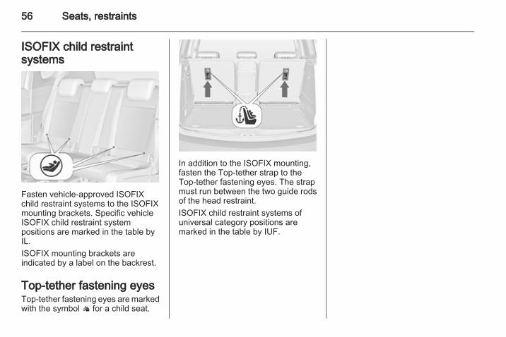
Fasten vehicle-approved ISOFIXchild restraint systems to the ISOFIXmounting brackets. Specific vehicleISOFIX child restraint systempositions are marked in the table byIL.ISOFIX mounting brackets areindicated by a label on the backrest.
Top-tether fastening eyesTop-tether fastening eyes are markedwith the symbol : for a child seat.
In addition to the ISOFIX mounting,fasten the Top-tether strap to theTop-tether fastening eyes. The strapmust run between the two guide rodsof the head restraint.ISOFIX child restraint systems ofuniversal category positions aremarked in the table by IUF.

Storage 57
Storage
Storage compartments ................ 57Load compartment ....................... 69Roof rack system ......................... 75Loading information ..................... 75
Storage compartmentsGlovebox
The glovebox features a pen holderand a coin holder.Inside the glovebox there isa compartment for the Owner'sManual. Pull the lug to open thecompartment.The glovebox should be closed whilstdriving.
Cupholders
Cupholders are located in the centreconsole.
Detachable cupholderA cupholder can be attached either tothe upper or lower guide rails in thefront console.

58 Storage
Fold the frame out of initial positionbefore using.NoteIf the cupholder is installed in thelower guide rail and the detachablearmrest in the upper guide rail, makesure that the frame is folded backinto the initial position before movingone of the parts. Otherwise thearmrest and the cupholder might bedamaged while moving them oneabove the other.
Armrest 3 38.
Installing cupholder
Press the buttons at the front and therear and insert the guide pins into theupper or lower guide rails. The frontbutton has to be pressed firmly.Release the buttons and move thecupholder until it engages audibly.NoteInstall the cupholder in the directionas shown in the graphic. Otherwisethe cupholder may not engageproperly.
Moving cupholder
Press the front button slightly andmove the cupholder to the desiredposition. Release the button andmove the cupholder until it engagesaudibly.
Removing cupholderPress the buttons at the front and therear and remove the cupholder. Thefront button has to be pressed firmly.The cupholder can also be installedon the folded centre rear seat 3 42.

Storage 59
Front storage
A storage compartment is locatednext to the steering wheel.
Sunglasses storage
Fold down and open.Do not use for storing heavy objects.
Underseat storage
Lift drawer at recessed edge and pullout. Maximum load: 3 kg. To close,push the drawer in and engage.

60 Storage
Armrest storageStorage in the detachablearmrest
Push button and fold the armrest lidupwards. The armrest containsa storage compartment.The armrest can also be installed onthe folded centre rear seat 3 42.
Rear carrier system
The rear carrier system (Flex-Fixsystem) allows bicycles to beattached to a pull-out carrierintegrated into the vehicle floor.The maximum load of the rear carriersystem is 40 kg. The maximum loadper bicycle is 20 kg.If not in use, the carrier system can beslid back into the vehicle floor.A multifunction box is offered as anaccessory for the rear carrier system.The transportation of other objects isnot permitted.
There must not be any objects on thebicycles that could become looseduring transportation.
ExtendingOpen the tailgate.
9 Warning
No persons may remain in theextension zone of the rear carriersystem, risk of injury.
Pull release lever up. The systemdisengages and travels quickly out ofthe bumper.

Storage 61
Completely pull out the rear carriersystem until you hear it engage.Ensure that it is not possible to pushin the rear carrier system withoutpulling the release lever again
9 Warning
It is only permissible to fit objectsto the rear carrier system if thesystem has been correctlyengaged. If the rear carrier systemwill not engage correctly, do not fitobjects to the system and slide thesystem back. Seek the assistanceof a workshop.
Install the tail lamps
First remove the rear (1), then thefront (2) tail lamp from the recesses.
Open out the lamp support on theback of the tail lamp completely.
Push the clamping lever down andpush the lamp support into theretainer until it engages.Perform this procedure for both taillamps.

62 Storage
Check the cable and lamp position tomake sure these are correctlyinstalled and are securely located.
Lock the rear carrier system
Swivel the right clamping lever (1)first, followed by the left clampinglever (2), until a resistance isnoticeable.
The rear carrier system is lockedwhen the clamping levers areswivelled by approx. 50°. Otherwisesafe functionality is not guaranteed.NoteClose the tailgate.

Storage 63
Unfold the number plate holder
Unfold the holder for the numberplate.Affix the number plate once beforefirst usage of the rear carrier system.
Unfold pedal crank recesses
Fold one or both pedal crankrecesses upwards until the diagonalsupport engages.
Remove the pedal crank mounts fromthe pedal crank recesses.

64 Storage
Adapting the rear carrier systemto a bicycle
Press the release lever and withdrawthe wheel recesses.
Push the release lever on the strapretainer and remove the strapretainer.
Prepare the bicycle forattachment
Rotate the left pedal (without a chaincog) vertically downwards. The pedalon the left pedal crank must behorizontal.The front bicycle must have its frontwheel facing left.The rear bicycle must have its frontwheel facing right.

Storage 65
Attaching a bicycle to the rearcarrier system
With the rotary lever on the pedalcrank recess, roughly adapt theadjustable pedal crank unit to theprotrusion of the pedal crank.If the bicycle has straight pedalcranks, unscrew the pedal crank unitcompletely (position 5).
If the bicycle has curved pedalcranks, screw in the pedal crank unitall the way (position 1).
Put on the bicycle. The pedal crankhere must be placed in the pedalcrank recess opening as shown in theillustration.
Caution
Make sure that the pedal does nottouch the surface of the rear endcarrier. Otherwise the cranksetmight be damaged during thetransport.
Insert pedal crank mount into outerrail of each pedal crank recess fromabove and slide downwards until atleast underneath the notching.

66 Storage
Attach the pedal crank by rotating theattachment screw on the pedal crankmount.
Place the wheel recesses such thatthe bicycle is more or less horizontal.Here, the distance between thepedals and the tailgate should be atleast 5 cm.Both bicycle tyres must be in thewheel recesses.
Caution
Make sure that the pedal does nottouch the surface of the rear endcarrier. Otherwise the cranksetmight be damaged during thetransport.
Align the bicycle in the longitudinaldirection of the vehicle: Slightlyloosen the pedal mount.Place the bicycle upright using therotary lever on the pedal crankrecess.If the two bicycles obstruct oneanother, the relative positions of thebicycles can be adapted by adjustingthe wheel recesses and the rotarylever on the pedal crank recess untilthe bicycles no longer touch oneanother. Make sure there is sufficientclearance from the vehicle.

Storage 67
Tighten the attachment screw for thepedal bearing mount hand-tight.Secure both bicycle wheels to wheelrecesses using strap retainers.Check the bicycle to make sure it issecure.The settings for the wheel recessesand on the rotary lever on the pedalcrank recess should be noted andsaved for each bicycle. Correctpresetting will facilitate refitting of thebicycle.
Removing a bicycle from therear carrier system
Undo strap retainers on both bicycletyres.Hold on to the bicycle, loosen theattachment screw for the pedalbearing mount, then lift the pedalbearing mount to remove it.
Retracting the rear carriersystem
Push the pedal crank mounts into thepedal crank recess like shown in thegraphic.
Insert the strap retainer and pulltightly downwards as far as possible.

68 Storage
Press release lever and slide in wheelrecesses all the way as far as they willgo.
Disengage the locking lever on thediagonal support and fold both pedalcrank recesses down.
9 Warning
Risk of pinching.
Remove number plate and fold downthe number plate holder.
Swivel first the left clamping lever (1),followed by the right clamping lever(2), until they stop.
Push the clamping lever down andpull both lamp supports out of therecesses.
Fold in the lamp supports on thebacks of the tail lamps.First place the front (1) tail lamp, thenthe rear (2) tail lamp in the recessesand push down as far as possible.Push cables all the way into all guidesin order to prevent damage.
Storage 69
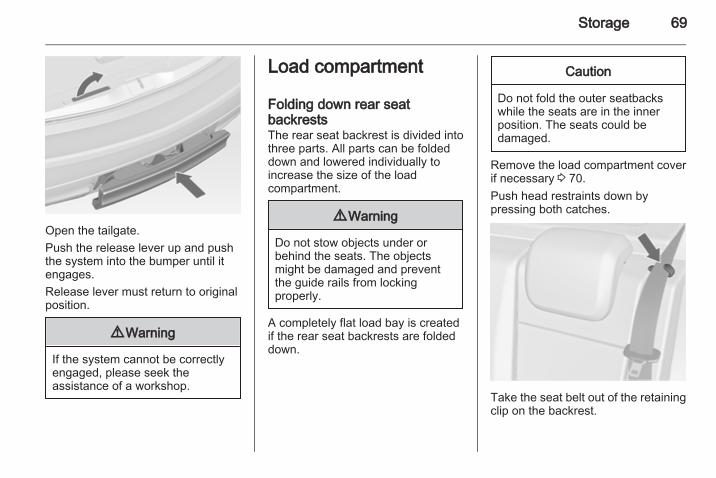
Open the tailgate.Push the release lever up and pushthe system into the bumper until itengages.Release lever must return to originalposition.
9 Warning
If the system cannot be correctlyengaged, please seek theassistance of a workshop.
Load compartment
Folding down rear seatbackrestsThe rear seat backrest is divided intothree parts. All parts can be foldeddown and lowered individually toincrease the size of the loadcompartment.
9 Warning
Do not stow objects under orbehind the seats. The objectsmight be damaged and preventthe guide rails from lockingproperly.
A completely flat load bay is createdif the rear seat backrests are foldeddown.
Caution
Do not fold the outer seatbackswhile the seats are in the innerposition. The seats could bedamaged.
Remove the load compartment coverif necessary 3 70.Push head restraints down bypressing both catches.
Take the seat belt out of the retainingclip on the backrest.

70 Storage
Pull the handle on the front side of thebackrest and fold down the backrestonto the seat cushion. The seat islowered automatically.The backrests can also be foldedfrom the load compartment.
Pull the handle on the back side of thebackrest and fold down the backrest.To fold up, pull the handle and raisethe backrests into an upright positionuntil they engage audibly.
9 Warning
Only drive the vehicle if thebackrests are securely locked intoposition. Otherwise there is a riskof personal injury or damage to theload or vehicle in the event ofheavy braking or a collision.
Rear storageOn the left side of the loadcompartment there is a stowagecompartment.
Turn the fastener anticlockwise andfold down the cover.
Load compartment coverDo not place any objects on the cover.
Storage 71
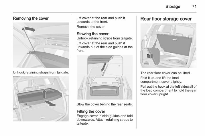
Removing the cover
Unhook retaining straps from tailgate.
Lift cover at the rear and push itupwards at the front.Remove the cover.
Stowing the coverUnhook retaining straps from tailgate.Lift cover at the rear and push itupwards out of the side guides at thefront.
Stow the cover behind the rear seats.
Fitting the coverEngage cover in side guides and folddownwards. Attach retaining straps totailgate.
Rear floor storage cover
The rear floor cover can be lifted.Fold it up and lift the loadcompartment cover slightly.Pull out the hook at the left sidewall ofthe load compartment to hold the rearfloor cover upright.

72 Storage
Double load-bay floorThe double load-bay floor can beinserted in the load compartment intwo positions:■ directly above the cover for the
spare wheel well or the rear floorcover,
■ in the upper openings in the loadcompartment.
To remove, lift the load-bay floorusing the recess and pull backwards.To insert, push the load-bay floorforwards in the corresponding guide,then lower.
If mounted in the upper position, thespace between the load-bay floor andthe spare wheel well cover can beused as a stowage compartment.In this position, if the rear seatbackrests are folded forwards, analmost completely flat load bay iscreated.In the upper position, the double load-bay floor is able to withstanda maximum load of 100 kg. In thelower position, the double load-bayfloor is able to withstand themaximum permissible load.In models with a tyre repair kit, thespare wheel recess may be used asan additional stowage compartment.
Lashing eyes
The lashing eyes are designed tosecure items against slippage, e.g.using lashing straps or luggage net.
Safety netThe safety net can be installed behindthe front seats.Passengers must not be transportedbehind the safety net.

Storage 73
Installation
There are two installation openings inthe roof frame: suspend rod of net atone side, push to the front andengage. Extend rod, suspend at otherside, push to the front and engage.
Suspend hooks of net tensioningbelts in lashing eyes in the floorbehind the front seats. Tension thenet by pulling the loose end of the belt.Suspend and tighten on both sides.
RemovalTilt length adjuster of the nettensioning belts upwards and detachthe belts on both sides. Disengagethe upper rod on one side, disengageother side and remove from theopenings.
Stowage
Place tensioning straps as shown infigure and align to net.

74 Storage
Roll the upper net rod down toapproximately over the middle.Place the upper net rod over thetensioning straps next to the lower netrod. The hooks on the upper net rodmust point away from the lower netrod.
Fasten Velcro tape tightly about thenet next to the length adjusters. Thelength adjusters and net rods must lieflat next to each other.Stow safety net in the space betweenthe double load-bay floor in the loadcompartment. Rear floor storagecover 3 71.
Folding trayLocated in the front seat backrests.Open by pulling upwards until itengages.Fold away by pressing down past theresistance point.Do not place any heavy objects on thefolding tray.
Warning triangle
Stow the warning triangle in the spaceat the rear side of the loadcompartment.
First aid kit
Stow the first aid kit and the highvisibility vest under the driver's seatusing the straps.

Storage 75
Depending on the vehicle, a box islocated under the driver's seat. Pullhandle and fold down the cover.Maximum load: 1,5 kg.
Roof rack systemRoof rackFor safety reasons and to avoiddamage to the roof, the vehicleapproved roof rack system isrecommended.Follow the installation instructionsand remove the roof rack when not inuse.
Detach the cover from each mountingpoint.
Loading information
■ Heavy objects in the loadcompartment should be placedagainst the seat backrests. Ensurethat the backrests are securelyengaged. If objects can be stacked,heavier objects should be placed atthe bottom.
■ Secure objects with lashing strapsattached to the lashing eyes 3 72.

76 Storage
■ Use the hook at the left sidewall ofthe load compartment for hangingup carrier bags. Pull out the hook.Maximum load: 3 kg.
■ Secure loose objects in the loadcompartment to prevent them fromsliding.
■ When transporting objects in theload compartment, the backrests ofthe rear seats must not be angledforward.
■ Do not allow the load to protrudeabove the upper edge of thebackrests.
■ Do not place any objects on theload compartment cover or theinstrument panel, and do not coverthe sensor on top of the instrumentpanel.
■ The load must not obstruct theoperation of the pedals, parkingbrake and gear selector, or hinderthe freedom of movement of thedriver. Do not place any unsecuredobjects in the interior.
■ Do not drive with an open loadcompartment.
9 Warning
Always make sure that the load inthe vehicle is securely stowed.Otherwise objects can be thrownaround inside the vehicle andcause personal injury or damageto the load or car.
■ The payload is the differencebetween the permitted grossvehicle weight (see identificationplate 3 190) and the EC kerbweight.
To calculate the payload, enter thedata for your vehicle in the Weightstable at the front of this manual.The EC kerb weight includesweights for the driver (68 kg),luggage (7 kg) and all fluids (tank90 % full).Optional equipment andaccessories increase the kerbweight.
■ Driving with a roof load increasesthe sensitivity of the vehicle tocross-winds and has a detrimentaleffect on vehicle handling due tothe vehicle's higher centre ofgravity. Distribute the load evenlyand secure it properly with retainingstraps. Adjust the tyre pressure andvehicle speed according to the loadconditions. Check and retighten thestraps frequently.The permissible roof load is 60 kg.The roof load is the combinedweight of the roof rack and the load.

Instruments and controls 77
Instruments andcontrols
Controls ....................................... 77Warning lights, gauges andindicators ..................................... 84Information displays ..................... 94Vehicle messages ........................ 98Trip computer ............................. 101Vehicle personalisation .............. 102
ControlsSteering wheel adjustment
Unlock lever, adjust steering wheel,then engage lever and ensure it isfully locked.Do not adjust steering wheel unlessvehicle is stationary and steeringwheel lock has been released.
Steering wheel controls
The Infotainment system, the cruisecontrol and a connected mobilephone can be operated via thecontrols on the steering wheel.Further information is available in theInfotainment system manual.Cruise control 3 136.

78 Instruments and controls
Heated steering wheel
Activate heating by pressing *button. Activation is indicated by theLED in the button.
The recommended grip areas of thesteering wheel are heated quickerand to a higher temperature than theother areas.
Horn
Press j.

Instruments and controls 79
Windscreen wiper/washerWindscreen wiper
2 = fast1 = slowP = interval wiping§ = off
For a single wipe when thewindscreen wiper is off, press thelever down.Do not use if the windscreen is frozen.Switch off in car washes.
Adjustable wiper interval
Wiper lever in position P.Turn the adjuster wheel to adjust thedesired wipe interval:shortinterval
= turn adjuster wheelupwards
longinterval
= turn adjuster wheeldownwards
Automatic wiping with rain sensor
P = automatic wiping with rainsensor
The rain sensor detects the amount ofwater on the windscreen andautomatically regulates the frequencyof the windscreen wiper.

80 Instruments and controls
Adjustable sensitivity of the rainsensor
Turn the adjuster wheel to adjust thesensitivity:lowsensitivity
= turn adjuster wheeldownwards
highsensitivity
= turn adjuster wheelupwards
Keep the sensor free from dust, dirtand ice.
Windscreen washer
Pull lever. Washer fluid is sprayedonto the windscreen and the wiperwipes a few times.
Rear window wiper/washer
Press the rocker switch to activate therear window wiper:upper position = short intervallower position = long intervalmiddle position = off

Instruments and controls 81
Push lever. Washer fluid is sprayedonto the rear window and the wiperwipes a few times.Do not use if the windscreen is frozen.Switch off in car washes.The rear window wiper comes onautomatically when the windscreenwiper is switched on and reverse gearis engaged.Activation or deactivation of thisfunction can be changed in the menuSettings in the Info-Display.Vehicle personalisation 3 102.
Outside temperature
A drop in temperature is indicatedimmediately and a rise in temperatureafter a time delay.If outside temperature drops to 3 °C,the symbol 4 illuminates in the DriverInformation Center withUplevel-Display or in theInfo-Display as a warning for icy roadconditions. 4 remains illuminateduntil temperatures reach at least5 °C.
Additionally a warning message isdisplayed in the Driver InformationCenter with Uplevel-Display.
9 Warning
The road surface may already beicy even though the displayindicates a few degrees above0 °C.
ClockDate and time are shown in theInfo-Display.

82 Instruments and controls
Set date and timePress the CONFIG button. The menuSettings is displayed.Select Time & Date.
Selectable setting options:■ Set time: Changes the time shown
on the display.■ Set date: Changes the date shown
on the display.■ Set time format: Changes
indication of hours between 12hours and 24 hours.
■ Set date format: Changesindication of date between MM/DD/YYYY and DD.MM.YYYY.
■ Display digital clock: Switches on/off indication of time on the display.
■ RDS clock synchronization: TheRDS signal of most VHFtransmitters automatically sets thetime. RDS time synchronisationcan take a few minutes. Sometransmitters do not send a correcttime signal. In such cases, it isrecommended to switch offautomatic time synchronisation.
Vehicle personalisation 3 102.
Power outlets
A 12 volt power outlet is located in thefront console.

Instruments and controls 83
A further 12 volt power outlet islocated in the rear console.Do not exceed the maximum powerconsumption of 120 watts.With ignition off, the power outlets aredeactivated. Additionally the poweroutlets are deactivated in the event oflow battery voltage.Electrical accessories that areconnected must comply with theelectromagnetic compatibilityrequirements laid down inDIN VDE 40 839.Do not connect any current-deliveringaccessories, e.g. electrical chargingdevices or batteries.Do not damage the outlet by usingunsuitable plugs.
Cigarette lighter
The cigarette lighter is located in thefront console.Press in cigarette lighter. It switchesoff automatically once the element isglowing. Pull out lighter.
Ashtrays
Caution
To be used only for ash and not forcombustible rubbish.
The portable ashtray can be placed inthe cupholders.

84 Instruments and controls
Warning lights, gaugesand indicatorsSpeedometer
Indicates vehicle speed.
Odometer
The bottom line displays the recordeddistance.
Trip odometerThe top line displays the recordeddistance since the last reset.To reset, hold the reset knobdepressed for a few seconds with theignition on.
Tachometer
Displays the engine speed.Drive in a low engine speed range foreach gear as much as possible.
Caution
If the needle is in the red warningzone, the maximum permittedengine speed is exceeded. Engineat risk.

Instruments and controls 85
Fuel gauge
Displays the fuel level in the tank.Control indicator i illuminates if thelevel in the tank is low. Refuelimmediately.Never run the tank dry.Because of the fuel remaining in thetank, the top-up quantity may be lessthan the specified tank capacity.
Engine coolanttemperature gauge
Displays the coolant temperature.left area = engine operating
temperature not yetreached
centralarea
= normal operatingtemperature
right area = temperature too high
Caution
If engine coolant temperature istoo high, stop vehicle, switch offengine. Danger to engine. Checkcoolant level.
Service displayThe engine oil life system lets youknow when to change the engine oiland filter. Based on drivingconditions, the interval at which anengine oil and filter change will beindicated can vary considerably.

86 Instruments and controls
In the Uplevel-Display the remainingoil life duration is displayed in theVehicle Information Menu.In the Midlevel-Display the remainingengine oil life duration is displayed bythe control indicator I. The ignitionmust be switched on, with the enginenot running.The menu and function can beselected via the buttons on the turnsignal lever.To display the remaining engine oillife duration:
Press the MENU button to select theVehicle Information Menu.
Turn the adjuster wheel to selectRemaining Oil Life.The system must be reset every timethe engine oil is changed to allowproper functionality. Seek theassistance of a workshop.Press the SET/CLR button to resetwhile applying the brake pedal. Theignition must be switched on, with theengine not running.When the system has calculated thatengine oil life has been diminished,Change Engine Oil Soon or a warningcode appears in the DriverInformation Center. Have engine oiland filter changed by a workshopwithin one week or 500 km(whichever occurs first).Driver Information Center 3 94.Service information 3 185.
Control indicatorsThe control indicators described arenot present in all vehicles. Thedescription applies to all instrumentversions.
Depending on the equipment theposition of the control indicators mayvary.When the ignition is switched on,most control indicators will illuminatebriefly as a functionality test.The control indicator colours mean:red = danger, important
reminderyellow = warning, information, faultgreen = confirmation of activationblue = confirmation of activationwhite = confirmation of activation

Instruments and controls 87
Control indicators in the instrument cluster

88 Instruments and controls
Control indicators in the centreconsole
Turn signalO illuminates or flashes green.
Illuminates brieflyThe parking lights are switched on.
FlashesA turn signal or the hazard warningflashers are activated.Rapid flashing: failure of a turn signallight or associated fuse, failure of turnsignal light on trailer.
Bulb replacement 3 152, Fuses3 161.Turn signals 3 111.
Seat belt reminderSeat belt reminder on frontseatsX illuminates or flashes red.
IlluminatesAfter the ignition has been switchedon until the seat belt has beenfastened.
FlashesAfter having started the engine fora maximum of 100 seconds until theseat belt has been fastened.Fastening the seat belt 3 44.
Seat belt status on rear seats> or X in the Driver InformationCenter flashes or illuminates.
IlluminatesAfter the ignition has been switchedon for a minimum of 35 seconds untilthe seat belt has been fastened.If an unfastened seat belt is fastenedwhilst driving.
FlashesAfter starting off when the seat belt isunfastened.Fastening the seat belt 3 44.
Airbag and belt tensionersv illuminates red.When the ignition is switched on, thecontrol indicator illuminates forapprox. 4 seconds. If it does notilluminate, does not go out after4 seconds or illuminates whilstdriving, there is a fault in the airbagsystem. Seek the assistance ofa workshop. The airbags and beltpretensioners may fail to trigger in theevent of an accident.Deployment of the belt pretensionersor airbags is indicated by continuousillumination of v.

Instruments and controls 89
9 Warning
Have the cause of the faultremedied immediately bya workshop.
Belt pretensioners, airbag system3 43, 3 47.
Airbag deactivationV illuminates yellow.The front passenger airbag isactivated.* illuminates yellow.The front passenger airbag isdeactivated 3 49.
9 Danger
Risk of fatal injury for a child usinga child restraint system togetherwith activated front passengerairbag.Risk of fatal injury for an adultperson with deactivated frontpassenger airbag.
Charging systemp illuminates red.Illuminates when the ignition isswitched on and goes out shortly afterthe engine starts.
Illuminates when the engine isrunningStop, switch off engine. Battery is notcharging. Engine cooling may beinterrupted. The brake servo unit maycease to be effective. Seek theassistance of a workshop.
Malfunction indicator lightZ illuminates or flashes yellow.Illuminates when the ignition isswitched on and goes out shortly afterthe engine starts.
Illuminates when the engine isrunningFault in the emission control system.The permitted emission limits may beexceeded. Seek the assistance ofa workshop immediately.
Flashes when the engine isrunningFault that could lead to catalyticconverter damage. Ease up on theaccelerator until the flashing stops.Seek the assistance of a workshopimmediately.
Service vehicle soong illuminates yellow.Additionally a warning message ora warning code is displayed.The vehicle needs a service.Seek the assistance of a workshop.Vehicle messages 3 98.
Brake and clutch systemBrake and clutch fluid level& illuminates red.The brake and clutch fluid level is toolow 3 150.

90 Instruments and controls
9 Warning
Stop. Do not continue yourjourney. Consult a workshop.
Operate pedal- illuminates or flashes yellow.
IlluminatesBrake pedal needs to be operated torelease the electrical parking brake3 133.
FlashesClutch pedal needs to be operated tostart the engine 3 125.
Electrical parking brakem illuminates or flashes red.
IlluminatesElectrical parking brake is applied3 133.
FlashesElectrical parking brake is not fullyapplied or released. Switch onignition, depress brake pedal andattempt to reset the system by firstreleasing and then applying theelectrical parking brake. If m remainsflashing, do not drive and seek theassistance of a workshop.
Electrical parking brakefaultj illuminates or flashes yellow.
IlluminatesElectrical parking brake is operatingwith degraded performance 3 133.
FlashesElectrical parking brake is in servicemode. Stop vehicle, apply andrelease the electrical parking brake toreset.
9 Warning
Have the cause of the faultremedied immediately bya workshop.
Antilock brake system(ABS)u illuminates yellow.Illuminates for a few seconds after theignition is switched on. The system isready for operation when the controlindicator goes out.If the control indicator does not go outafter a few seconds, or if it illuminateswhile driving, there is a fault in theABS. The brake system remainsoperational but without ABSregulation.Antilock brake system 3 132.
Upshift[ illuminates green.Upshifting is recommended for fuelsaving.
Instruments and controls 91
Variable effort steeringc illuminates yellow.Fault in variable effort steeringsystem. This may lead to a higher orlower steering effort. Consulta workshop.
Ultrasonic parking assistr illuminates yellow.Fault in systemorFault due to sensors that are dirty orcovered by ice or snoworInterference due to external sourcesof ultrasound. Once the source ofinterference is removed, the systemwill operate normally.Have the cause of the fault in thesystem remedied by a workshop.Ultrasonic parking assist 3 137.
Electronic Stability Controloffn illuminates yellow.The system is deactivated.
Electronic Stability Controland Traction Controlsystemb illuminates or flashes yellow.
IlluminatesA fault in the system is present.Continued driving is possible. Drivingstability, however, may deterioratedepending on road surfaceconditions.Have the cause of the fault remediedby a workshop.
FlashesThe system is actively engaged.Engine output may be reduced andthe vehicle may be brakedautomatically to a small degree.
Electronic stability control 3 135,Traction control system 3 134.
Traction Control system offk illuminates yellow.The system is deactivated.
Preheating! illuminates yellow.Preheating is activated. Onlyactivates when outside temperatureis low.
Diesel particle filter% illuminates or flashes yellow.The diesel particle filter requirescleaning.Continue driving until % goes out. Ifpossible do not allow engine speed todrop below 2000 rpm.
IlluminatesThe diesel particle filter is full. Startcleaning process as soon aspossible.

92 Instruments and controls
FlashesThe maximum filling level of the filteris reached. Start cleaning processimmediately to avoid damage to theengine.Diesel particle filter 3 127.
Deflation detection systemw illuminates or flashes yellow.
IlluminatesDeflation detected. Stop immediatelyand check tyre pressure.
FlashesFault in system. Consult a workshop.Deflation detection system 3 169.
Engine oil pressureI illuminates red.Illuminates when the ignition isswitched on and goes out shortly afterthe engine starts.
Illuminates when the engine isrunning
Caution
Engine lubrication may beinterrupted. This may result indamage to the engine and/orlocking of the drive wheels.
1. Depress clutch.2. Select neutral gear, set selector
lever to N.3. Move out of the flow of traffic as
quickly as possible withoutimpeding other vehicles.
4. Switch off ignition.
9 Warning
When the engine is off,considerably more force is neededto brake and steer.Do not remove key until vehicle isstationary, otherwise the steeringwheel lock could engageunexpectedly.
Check oil level before seekingassistance of a workshop 3 148.
Low fueli illuminates yellow.Level in fuel tank is too low.Catalytic converter 3 128.Bleeding the diesel fuel system3 151.
Immobiliserd flashes yellow.Fault in the immobiliser system. Theengine cannot be started.
Reduced engine power# illuminates yellow.The engine power is limited. Consulta workshop.
Exterior light8 illuminates green.The exterior lights are on 3 107.

Instruments and controls 93
l illuminates green.The automatic light control isswitched on 3 108.
High beamC illuminates blue.Illuminated when high beam is on andduring headlight flash 3 108.
Adaptive forward lightingf illuminates or flashes yellow.
IlluminatesFault in system.Seek the assistance of a workshop.
FlashesSystem switched to symmetrical lowbeam.Control indicator f flashes for approx.4 seconds after the ignition isswitched on as a reminder that thesystem has been activated 3 109.Automatic light control 3 108.
Daytime running lightV illuminates green.The daytime running light is on.
Fog light> illuminates green.The front fog lights are on 3 111.
Rear fog lightr illuminates yellow.The rear fog light is on 3 111.
Cruise controlm illuminates white or green.
Illuminates whiteThe system is on.
Illuminates greenA certain speed is stored.Cruise control 3 136
Door openh illuminates red.
A door or the tailgate is open.
Automatic locking^ illuminates amber.Fault in the automatic locking system.The rear doors are possibly notsecured against opening.
9 Warning
Stop your journey immediately!Follow the instructions asdescribed in paragraph "Fault inthe automatic locking system"before continuing your journey3 24.Consult a workshop.

94 Instruments and controls
Information displaysDriver Information Center
The Driver Information Center (DIC)is located in the instrument clusterbetween speedometer andtachometer. It is available asMidlevel- or Uplevel-Display.
The following main menus,depending on the vehicleconfiguration, can be selected:■ Vehicle Information Menu■ Trip/Fuel Information MenuSome of the displayed functions differbetween vehicle driving and standstilland some functions are only activewhen the vehicle is driving.Vehicle personalisation 3 102,Memorised settings 3 21.
Selecting menus and functionsThe menus and functions can beselected via the buttons on the turnsignal lever.
Press the MENU button to switchbetween the menus or to return froma submenu to the next higher menulevel.

Instruments and controls 95
Turn the adjuster wheel to highlighta menu option or to set a numericvalue.
Press the SET/CLR button to selecta function or to confirm a message.
Vehicle Information MenuPress the MENU button to select theVehicle Information Menu.Turn the adjuster wheel to select oneof the submenus. Press the SET/CLR button to confirm.
Follow the instructions given in thesubmenus.Possible submenus:■ Unit: Displayed units can be
changed.■ Remaining Oil Life: 3 85
■ Speed Warning: If exceeding thepreset speed, a warning chime willbe activated.
■ Language: Displayed language canbe changed.
Selection and indication can bedifferent between Midlevel- andUplevel-Display.
Trip/Fuel Information Menu
Trip/Fuel Information Menu, TripComputer 3 101.

96 Instruments and controls
Graphic-Info-Display,Colour-Info-DisplayDepending on the vehicleconfiguration the vehicle hasa Graphic- or Colour-Info-Display.The Info-Display is located in theinstrument panel above theInfotainment system.
Graphic-Info-Display
Depending on the Infotainmentsystem, the Graphic-Info-Display isavailable in two versions.
Graphic-Info-Display indicates:■ time 3 81■ outside temperature 3 81■ date 3 81■ Infotainment system, see
description for Infotainment system■ settings for vehicle personalisation3 102
Colour-Info-Display
The Colour-Info-Display indicates incolour:■ time 3 81■ outside temperature 3 81■ date 3 81■ Infotainment system, see
description for Infotainment system■ navigation, see description for
Infotainment system■ system settings

Instruments and controls 97
■ vehicle messages 3 98■ settings for vehicle personalisation3 102
The type of information and how it isdisplayed depends on the equipmentof the vehicle and the settings made.
Selecting menus and settingsMenus and settings are accessed viathe display.
Selections are made via:■ menus■ function buttons and multifunction
knob of the Infotainment system
Selecting with the Infotainmentsystem
Select a function via the Infotainmentsystem buttons. The menu of theselected function is displayed.The multifunction knob is used toselect an item and to confirm.
Multifunction knobThe multifunction knob is the centralcontrol element for the menus:Turn■ To mark a menu option■ To set a numeric value or to display
a menu option
Press (the outer ring)■ To select or activate the marked
option■ To confirm a set value■ To switch a system function on/offBACK buttonPress button to:■ exit a menu without changing
settings■ return from a submenu to a higher
menu level■ delete the last character in
a character sequencePress and hold the button for a fewseconds to delete the entire entry.Vehicle personalisation 3 102,Memorised settings 3 21.
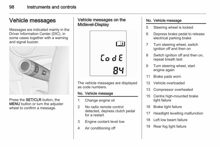
98 Instruments and controls
Vehicle messagesMessages are indicated mainly in theDriver Information Center (DIC), insome cases together with a warningand signal buzzer.
Press the SET/CLR button, theMENU button or turn the adjusterwheel to confirm a message.
Vehicle messages on theMidlevel-Display
The vehicle messages are displayedas code numbers.
No. Vehicle message
1 Change engine oil
2 No radio remote controldetected, depress clutch pedalfor a restart
3 Engine coolant level low
4 Air conditioning off
No. Vehicle message
5 Steering wheel is locked
6 Depress brake pedal to releaseelectrical parking brake
7 Turn steering wheel, switchignition off and then on
8 Switch ignition off and then on,repeat breath test
9 Turn steering wheel, startengine again
11 Brake pads worn
12 Vehicle overloaded
13 Compressor overheated
15 Centre high-mounted brakelight failure
16 Brake light failure
17 Headlight levelling malfunction
18 Left low beam failure
19 Rear fog light failure

Instruments and controls 99
No. Vehicle message
20 Right low beam failure
21 Left front sidelight failure
22 Right front sidelight failure
23 Reversing light failure
24 Number plate light failure
25 Left front turn signal failure
26 Left rear turn signal failure
27 Right front turn signal failure
28 Right rear turn signal failure
29 Check trailer brake light
30 Check trailer reversing light
31 Check left trailer turn signal
32 Check right trailer turn signal
33 Check trailer rear fog light
34 Check trailer rear light
35 Replace battery in radio remotecontrol
No. Vehicle message
48 Clean side blind zone alertsystem
50 Activated pedestrian protectionsystem, reset bonnet
51 Compass unavailable
53 Tighten gas cap
54 Water in diesel fuel filter
55 Diesel particle filter is full3 127
59 Open and then close driverwindow
60 Open and then close frontpassenger window
61 Open and then close rear leftwindow
62 Open and then close rear rightwindow
65 Theft attempted
66 Service theft alarm system
No. Vehicle message
67 Service steering wheel lock
68 Service power steering
69 Service suspension system
70 Service level control system
71 Service rear axle
74 Service AFL
75 Service air conditioning
76 Service side blind zone alertsystem
78 Service pedestrian protectionsystem
79 Top up engine oil
80 Change transmission fluid
81 Service transmission
82 Change engine oil soon
83 Service adaptive cruise control
84 Engine power is reduced

100 Instruments and controls
No. Vehicle message
94 Shift to park before exiting
95 Service airbag
Vehicle messages on theUplevel-Display
The vehicle messages are displayedas text. Follow the instructions givenin the messages.The system displays messagesregarding the following topics:■ Fluid levels■ Anti-theft alarm system
■ Brakes■ Drive systems■ Ride control systems■ Cruise control■ Object detection systems■ Lighting, bulb replacement■ Wiper/washer system■ Doors, windows■ Radio remote control■ Seat belts■ Airbag systems■ Engine and transmission■ Tyre pressure■ Diesel particle filter
Vehicle messages on theColour-Info-DisplaySome important messages appearadditionally in theColour-Info-Display. Press themultifunction knob to confirma message. Some messages onlypop up for a few seconds.
Warning chimesWhen starting the engine orwhilst driving■ If seat belt is not fastened.■ If a door or the tailgate is not fully
closed when starting off.■ If a certain speed is exceeded with
parking brake applied.■ If a programmed speed is
exceeded.■ If a warning message or a warning
code appears in the DriverInformation Center.
■ If the parking assist detects anobject.
■ If a fault in the automatic lockingsystem is detected.
When the vehicle is parked and/or the driver's door is opened■ When the key is in the ignition
switch.■ With exterior lights on.

Instruments and controls 101
Trip computerThe menus and functions can beselected via the buttons on the turnsignal lever.
Press the MENU button to select theTrip/Fuel Information Menu.
Turn the adjuster wheel to select oneof the submenus:■ Trip odometer 1■ Trip odometer 2■ Range■ Average consumption■ Instantaneous consumption■ Average speed■ Digital speed
The information of the two tripcomputers can be reset separately,making it possible to display differenttrip distances.To reset, press the reset knob orpress the SET/CLR button for a fewseconds.
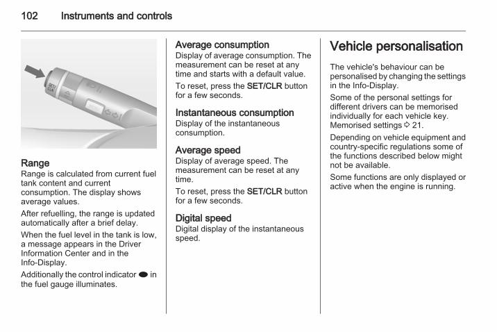
102 Instruments and controls
RangeRange is calculated from current fueltank content and currentconsumption. The display showsaverage values.After refuelling, the range is updatedautomatically after a brief delay.When the fuel level in the tank is low,a message appears in the DriverInformation Center and in theInfo-Display.Additionally the control indicator i inthe fuel gauge illuminates.
Average consumptionDisplay of average consumption. Themeasurement can be reset at anytime and starts with a default value.To reset, press the SET/CLR buttonfor a few seconds.
Instantaneous consumptionDisplay of the instantaneousconsumption.
Average speedDisplay of average speed. Themeasurement can be reset at anytime.To reset, press the SET/CLR buttonfor a few seconds.
Digital speedDigital display of the instantaneousspeed.
Vehicle personalisationThe vehicle's behaviour can bepersonalised by changing the settingsin the Info-Display.Some of the personal settings fordifferent drivers can be memorisedindividually for each vehicle key.Memorised settings 3 21.Depending on vehicle equipment andcountry-specific regulations some ofthe functions described below mightnot be available.Some functions are only displayed oractive when the engine is running.

Instruments and controls 103
Personal settings in theGraphic-Info-Display
Press the CONFIG button. The menuSettings is displayed.
The following settings can beselected by turning and pressing themultifunction knob:■ Time Date■ Radio settings■ Phone settings■ Vehicle settings■ Restore factory settingsIn the corresponding submenus thefollowing settings can be changed:
Time DateSee Clock 3 81.
Radio settingsSee description for Infotainmentsystem.
Phone settingsSee description for Infotainmentsystem.
Vehicle settings
■ Climate and air qualityAuto fan speed: Modifies the fanregulation.Automatic air recirculation:Modifies AQS (Air Quality Sensor)sensitivity low / high.

104 Instruments and controls
Climate control mode: Activate ordeactivate cooling.Auto rear demist: Automaticactivation of rear heated window.
■ Comfort settingsChime volume: Change the volumeof warning chimes.Personalization by driver: Activateor deactivate the personalisationfunction.Rear auto wipe in reverse: Activateor deactivate automatic switchingon of the rear window wiper whenreverse gear is engaged.
■ Park assist / Collision detection
Park assist: Activate or deactivatethe ultrasonic parking assist .
■ LanguagesSelection of the desired language.
■ Exterior ambient lightingDuration upon exit of vehicle:Activate or deactivate and changethe duration of exit lighting.Exterior lighting by unlocking:Activate or deactivate the welcomelighting.
■ Remote locking, unlocking, startingRemote door unlock: Change theconfiguration to unlock only thedriver's door or the whole vehiclewhilst unlocking.
■ Restore factory settingsRestore factory settings: Reset allsettings to the default settings.
Personal settings in theColour-Info-Display
Press the CONFIG button. The menuSettings is displayed.

Instruments and controls 105
The following settings can beselected by turning and pressing themultifunction knob:■ Time & Date■ Radio settings■ Phone settings■ Navigation settings■ Vehicle settings■ Display settings■ Restore factory settingsIn the corresponding submenus thefollowing settings can be changed:
Time & DateSee Clock 3 81.
Radio settingsSee description for Infotainmentsystem.
Phone settingsSee description for Infotainmentsystem.
Navigation settingsSee description for Infotainmentsystem.
Vehicle settings
■ Climate and air qualityAuto fan speed: Modifies the fanregulation.Automatic air recirculation:Modifies AQS (Air Quality Sensor)sensitivity low / high.Climate control mode: Activate ordeactivate cooling.Auto rear demist: Automaticactivation of rear heated window.
■ Comfort settingsChime volume: Change the volumeof warning chimes.Rear auto wipe in reverse: Activateor deactivate automatic switching

106 Instruments and controls
on of the rear window wiper whenreverse gear is engaged.
■ Park assist / Collision detectionPark assist: Activate or deactivatethe ultrasonic parking assist.
■ LanguagesSelection of the desired language.
■ Exterior ambient lightingDuration upon exit of vehicle:Activate or deactivate and changethe duration of exit lighting.Exterior lighting by unlocking:Activate or deactivate the welcomelighting.
■ Lock / Unlock / StartRemote door unlock: Change theconfiguration to unlock only thedriver's door or the whole vehiclewhilst unlocking.
■ Restore factory settingsRestore factory settings: Reset allsettings to the default settings.
Display settingsSelectable display settings:■ Day mode: Optimisation for
daylight conditions.■ Night mode: Optimisation for
darkness.■ Automatic mode:
Vehicles without light sensor:The display changes the modewhen the vehicle lights areswitched on/off.Vehicles with light sensor:The display changes the mode dueto the exterior lighting conditionsindependently from the vehiclelights.

Lighting 107
Lighting
Exterior lighting .......................... 107Interior lighting ........................... 112Lighting features ........................ 114
Exterior lightingLight switch
Turn light switch:AUTO = automatic light control:
Headlights are switchedon and off automaticallydepending on externallighting conditions.
m = activation or deactivationof the automatic lightcontrol. Switch turns backto AUTO.
7 = off
8 = sidelights9 = headlights
In the Driver Information Center withUplevel-Display, the current status ofthe automatic light control isdisplayed.When switching on the ignition,automatic light control is active.Control indicator 8 3 92, Automaticlight control indicator l 3 92.
Tail lightsTail lights are illuminated togetherwith headlights and sidelights.

108 Lighting
Automatic light control
Automatic light control functionWhen the automatic light controlfunction is switched on and theengine is running, the systemswitches between daytime runninglight and automatic headlightdepending on lighting conditions.
Daytime running lightDaytime running light increasesvisibility of the vehicle during daylight.In some countries also the tail lightsare on.
Automatic headlight activationDuring poor lighting conditions theheadlights are switched on.
Tunnel detectionWhen a tunnel is entered theheadlights are switched on withoutdelay.Adaptive forward lighting 3 110.
High beam
To switch from low to high beam,push lever.To switch to low beam, push leveragain or pull.
Headlight flashTo activate the headlight flash, pulllever.
Headlight rangeadjustmentManual headlight rangeadjustment
To adapt headlight range to thevehicle load to prevent dazzling: turnthumb wheel ? to required position.

Lighting 109
0 = front seats occupied1 = all seats occupied2 = all seats occupied and load
compartment laden3 = driver's seat occupied and load
compartment laden.
Headlights when drivingabroadThe asymmetrical headlight beamextends visibility at the edge of theroad at the passenger side.However, when driving in countrieswhere traffic drives on the oppositeside of the road, adjust the headlightsto prevent dazzling of oncomingtraffic.
Vehicles without AdaptiveForward Lighting
Turn the adjusting screws with thescrewdriver clockwise for half a turn.The adjusting screws are located atthe headlights above the low beamcaps 3 152.For deactivation turn the adjustingscrews anticlockwise for half a turn.
Caution
Have the adjustment of theheadlights checked afterdeactivation.We recommend consultinga workshop.
Vehicles with Adaptive ForwardLighting
1. Turn key to position 0.2. Wait until control indicator m
goes off.3. Pull turn signal lever and hold.

110 Lighting
4. Switch on ignition.5. After approx. 5 seconds the
control indicator f starts flashingand an acoustic signal sounds.
Control indicator f 3 93.Every time the ignition is switched on,f flashes as a reminder for approx.4 seconds.For deactivation operate the sameprocedure as described above. f willnot flash when function isdeactivated.
Adaptive forward lightingAdaptive forward lighting ensuresbetter illumination of bends, crossingsand narrow bends.
Curve lighting
The light beam pivots based onsteering wheel position and speed.
Corner lightingOn tight bends or when turning off,depending on the steering angle orthe indicator light signal, an additionalleft or right reflector is switched onwhich illuminates the road in thedirection of travel. It is activated up toa speed of 40 km/h.
Reversing functionIf the headlights are on and reversegear is engaged, both corner lightsare switched on. They remainilluminated for 20 seconds afterdisengaging reverse gear or untildriving faster than 17 km/h forward.
Hazard warning flashers
Operated with the ¨ button.In the event of an accident with airbagdeployment the hazard warningflashers are activated automatically.

Lighting 111
Turn and lane-changesignals
lever up = right turn signallever down = left turn signal
If the lever is moved past theresistance point, the turn signal isswitched on constantly. When thesteering wheel moves back, the turnsignal is automatically deactivated.For three flashes, e.g. when changinglanes, press the lever until resistanceis felt and then release.
With a trailer connected, turn signalflashes six times when pressing thelever until resistance is felt and thenreleasing.Move the lever to the resistance pointand hold for longer indication.Switch the turn signal off manually bymoving the lever to its originalposition.
Front fog lights
Operated with the > button.Light switch in position AUTO:switching on front fog lights will switchheadlights on automatically.
Rear fog lights
Operated with the r button.Light switch in position AUTO:switching on rear fog light will switchheadlights on automatically.Light switch in position 8: rear foglight can only be switched on withfront fog lights.The vehicle rear fog light isdeactivated when towing.

112 Lighting
Parking lights
When the vehicle is parked, theparking lights on one side can beactivated:1. Switch off ignition.2. Move turn signal lever all the way
up (right parking lights) or down(left parking lights).
Confirmed by a signal and thecorresponding turn signal controlindicator.
Reversing lightsThe reversing lights come on whenthe ignition is on and reverse gear isselected.
Misted light coversThe inside of the light housing maymist up briefly in poor, wet and coldweather conditions, in heavy rain orafter washing. The mist disappearsquickly by itself; to help switch on theheadlights.
Interior lightingInstrument panelillumination control
Brightness of the following lights canbe adjusted when the exterior lightsare on:■ Instrument panel illumination■ Info-Display■ Illuminated switches and operation
elementsTurn thumb wheel A until the requiredbrightness is obtained.

Lighting 113
On vehicles with light sensor thebrightness can only be adjusted whenthe exterior lights are on and the lightsensor detects night conditions.
Interior lightsDuring entry and exit of the vehicle,the front and rear courtesy lightsautomatically switch on and then offafter a delay.NoteIn the event of an accident withairbag deployment the courtesylights are turned on automatically.
Front courtesy light
Operate rocker switch:w = automatic switching on
and off.press u = on.press v = off.
Rear courtesy lights
Illuminate in conjunction with the frontcourtesy light depending on rockerswitch position.
Reading lights
Operated with s and t buttons infront and rear courtesy lights.
Sunvisor lightsIlluminate when the cover is opened.

114 Lighting
Lighting featuresCentre console lightingSpotlight incorporated in the interiorlighting comes on when headlightsare switched on.
Entry lightingWelcome lightingHeadlights, tail lights, reversing lights,number plate lights, instrument panellight and interior lights are switchedon for a short time by unlocking thevehicle with the radio remote control.This function facilitates locating thevehicle when it is dark.The lighting switches off immediatelywhen the ignition key is turned toposition 1 3 125.Activation or deactivation of thisfunction can be changed in the menuSettings in the Info-Display. Vehiclepersonalisation 3 102.The settings can be saved for the keybeing used 3 21.
The following lights will additionallyswitch on when the driver's door isopened:■ All switches■ Driver Information Center
Exit lightingThe following lights switch on if thekey is removed from the ignitionswitch:■ Interior lights■ Instrument panel lightThey will switch off automatically aftera delay. Theatre lighting is activatedif the driver's door is opened duringthis time.The puddle light illuminates when theaccording door is opened.Headlights, tail lights, reversing lightsand number plate lights illuminate thesurrounding area for an adjustabletime after leaving the vehicle.
Switching on
1. Switch off ignition.2. Remove ignition key.3. Open driver's door.4. Pull turn signal lever.5. Close driver's door.
If the driver's door is not closed thelights switch off after 2 minutes.Exit lighting is switched offimmediately if the turn signal lever ispulled while the driver's door is open.

Lighting 115
Activation, deactivation and durationof this function can be changed in themenu Settings in the Info-Display.Vehicle personalisation 3 102.The settings can be saved for the keybeing used 3 21.
Battery dischargeprotectionSwitching off electric lightsTo prevent discharge of the batterywhen the ignition is switched off,some interior lights are switched offautomatically after some time.

116 Climate control
Climate control
Climate control systems ............. 116Air vents ..................................... 121Maintenance .............................. 122
Climate control systemsHeating and ventilationsystem
Controls for:■ Temperature■ Air distribution■ Fan speed■ Demisting and defrostingHeated rear window Ü 3 32.
Temperaturered = warmblue = cold
Heating will not be fully effective untilthe engine has reached normaloperating temperature.
Air distributions = to windscreen and front door
windowsM = to head area via adjustable air
ventsK = to foot well
All combinations are possible.
Fan speedAdjust the air flow by switching the fanto the desired speed.
Demisting and defrosting■ Press button V: fan automatically
switches to higher speed, the airdistribution is directed towards thewindscreen.
■ Set temperature control to warmestlevel.
■ Switch on heated rear window Ü.■ Open side air vents as required and
direct them towards the doorwindows.

Climate control 117
Air conditioning system
In addition to the heating andventilation system, the airconditioning system has:n = cooling4 = air recirculation
Heated seats ß 3 40, Heatedsteering wheel * 3 78.
Cooling nOperated with the n button and isfunctional only when the engine andfan are running.
The air conditioning system cools anddehumidifies (dries) as soon as theoutside temperature is slightly abovethe freezing point. Thereforecondensation may form and drip fromunder the vehicle.If no cooling or drying is required,switch the cooling system off to savefuel.
Air recirculation system 4Operated with the 4 button.
9 Warning
The exchange of fresh air isreduced in air recirculation mode.In operation without cooling the airhumidity increases, so thewindows may mist up. The qualityof the passenger compartment airdeteriorates, which may cause thevehicle occupants to feel drowsy.
Maximum coolingBriefly open the windows so that hotair can disperse quickly.
■ Cooling n on.■ Air circulation system 4 on.■ Press air distribution switch M.■ Set temperature control to coldest
level.■ Set fan speed to highest level.■ Open all vents.
Demisting and defrosting thewindows V
■ Press button V: fan automaticallyswitches to higher speed, the airdistribution is directed towards thewindscreen.

118 Climate control
■ Switch cooling n on.■ Set temperature control to warmest
level.■ Switch on heated rear window Ü.■ Open side air vents as required and
direct them towards the doorwindows.
Electronic climate controlsystemThe dual zone climate control allowsdifferent climatisation temperaturesfor driver and front passenger side.
Controls for:■ Temperature on driver side■ Air distribution■ Fan speed■ Temperature on front passenger
sideAUTO = automatic modeu = manual air recirculationt = automatic air recirculationV = demisting and defrosting
Heated rear window Ü 3 32.The preselected temperature isautomatically regulated. In theautomatic mode the fan speed and airdistribution automatically regulate theair flow.The system can be manually adaptedvia the use of air distribution and airflow controls.
Each change of settings is shown inthe Info-Display for a few seconds.The electronic climate control systemis only fully operational when theengine is running.
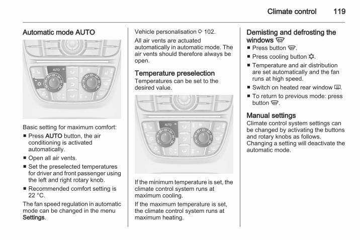
Climate control 119
Automatic mode AUTO
Basic setting for maximum comfort:■ Press AUTO button, the air
conditioning is activatedautomatically.
■ Open all air vents.■ Set the preselected temperatures
for driver and front passenger usingthe left and right rotary knob.
■ Recommended comfort setting is22 °C.
The fan speed regulation in automaticmode can be changed in the menuSettings.
Vehicle personalisation 3 102.All air vents are actuatedautomatically in automatic mode. Theair vents should therefore always beopen.
Temperature preselectionTemperatures can be set to thedesired value.
If the minimum temperature is set, theclimate control system runs atmaximum cooling.If the maximum temperature is set,the climate control system runs atmaximum heating.
Demisting and defrosting thewindows V■ Press button V.■ Press cooling button n.■ Temperature and air distribution
are set automatically and the fanruns at high speed.
■ Switch on heated rear window Ü.■ To return to previous mode: press
button V.
Manual settingsClimate control system settings canbe changed by activating the buttonsand rotary knobs as follows.Changing a setting will deactivate theautomatic mode.

120 Climate control
Press lower button x to decrease orupper button x to increase fan speed.The fan speed is indicated by thenumber of segments in the display.Pressing the lower button longer, fanand cooling are switched off.Pressing the upper button longer, thefan runs at maximum speed.To return to automatic mode: PressAUTO button.
Air distributionPress s, M or K for desiredadjustment. Activation is indicated bythe LED in the button.
s = to windscreen and front doorwindows
M = to head area via adjustable airvents
K = to foot well
All combinations are possible.Return to automatic air distribution:Deactivate corresponding setting orpress button AUTO.
CoolingActivate or deactivate with the nbutton.The air conditioning system cools anddehumidifies (dries) when outsidetemperature is above a specific level.Therefore condensation may formand drip from under the vehicle.If no cooling or drying is required,switch the cooling system off to savefuel.
Air recirculation mode
9 Warning
The exchange of fresh air isreduced in air recirculation mode.In operation without cooling the airhumidity increases, so thewindows may mist up. The qualityof the passenger compartment airdeteriorates, which may cause thevehicle occupants to feel drowsy.

Climate control 121
Automatic air recirculation tThe automatic air recirculationsystem has an air quality sensorwhich can switch automatically torecirculation.Activation is indicated by the LED inthe button.Switch to manual air recirculation asnecessary.
Manual air recirculation uPress button once to activate themanual air recirculation mode.Activation is indicated by the LED inthe button.
Basic settingsSome settings can be changed in themenu Settings in the Info-Display.Vehicle personalisation 3 102.
Auxiliary heaterAir heaterQuickheat is an electric auxiliary airheater which automatically warms upthe passenger compartment morequickly.
Air ventsAdjustable air vents
To open the vent, turn the adjusterwheel to the right. Adjust the airamount at the vent outlet by turningthe adjuster wheel.

122 Climate control
Direct the flow of air by tilting andswivelling the slats.To close the vent, turn the adjusterwheel to the left.
9 Warning
Do not attach any objects to theslats of the air vents. Risk ofdamage and injury in case of anaccident.
Fixed air ventsAdditional air vents are locatedbeneath the windscreen and doorwindows and in the foot wells.
MaintenanceAir intake
The air intake in front of thewindscreen in the enginecompartment must be kept clear toallow air intake. Remove any leaves,dirt or snow.
Pollen filterCabin air filtrationA particle filter cleans the cabin airfrom dust, soot, pollen and spores.
Active carbon filterIn addition to the particle filter theactive carbon filter reduces odours.
Air conditioning regularoperationIn order to ensure continuouslyefficient performance, cooling mustbe operated for a few minutes oncea month, irrespective of the weatherand time of year. Operation withcooling is not possible when theoutside temperature is too low.
ServiceFor optimal cooling performance, it isrecommended to annually check theclimate control system, starting3 years after initial vehicleregistration, including:■ Functionality and pressure test■ Heating functionality■ Leakage check■ Check of drive belts

Climate control 123
■ Cleaning of condenser andevaporator drainage
■ Performance check

124 Driving and operating
Driving and operating
Driving hints ............................... 124Starting and operating ............... 124Engine exhaust .......................... 127Automatic transmission .............. 128Manual transmission .................. 131Brakes ........................................ 132Ride control systems ................. 134Cruise control ............................. 136Object detection systems ........... 137Fuel ............................................ 139Towing ....................................... 142
Driving hintsControl of the vehicleNever coast with engine notrunningMany systems will not function in thissituation (e.g. brake servo unit, powersteering). Driving in this manner isa danger to yourself and others.
Idle boostIf charging of the battery is requireddue to battery condition, the poweroutput of the generator has to beincreased. This will be achieved by anidle boost which may be audible.On vehicles with Uplevel-Display,a message appears in the DriverInformation Center.
PedalsTo ensure the pedal travel isuninhibited, there must be no mats inthe area of the pedals.
Starting and operatingNew vehicle running-inDo not brake unnecessarily hard forthe first few journeys.During the first drive, smoke mayoccur because of wax and oilevaporating off the exhaust system.Park the vehicle in the open fora while after the first drive and avoidinhaling the fumes.During the running-in period fuel andengine oil consumption may behigher and the cleaning process ofthe diesel particle filter may takeplace more often.Diesel particle filter 3 127.

Driving and operating 125
Ignition switch positions
0 = Ignition off1 = Steering wheel lock released,
ignition off2 = Ignition on, for diesel engine:
preheating3 = Starting
Retained power offThese vehicle accessories can beused for up to 10 minutes after theengine is turned off:■ Infotainment system■ Power windows■ Power outletsPower to the infotainment system willcontinue to operate for up to10 minutes or until the driver door isopened.Power to the power windows willcontinue to operate for up to10 minutes or until any door isopened.Ignition switch postions 3 125
Starting the engine
Manual transmission: operate clutch.Automatic transmission: operatebrake and move the selector lever toP or N.Do not operate accelerator pedal.Diesel engine: turn the key to position2 for preheating until controlindicator ! goes out.Turn the key briefly to position 3 andrelease: an automatic procedureoperates the starter with a short delayas long as the engine is running, seeAutomatic Starter Control.

126 Driving and operating
Before restarting or to switch off theengine, turn the key back to 0.
Starting the vehicle at lowtemperaturesThe start of the engine withoutadditional heaters is possible down to-25 °С for diesel engines and -30 °Cfor petrol engines. Required is anengine oil with the correct viscosity,the correct fuel, performed servicesand a sufficiently charged battery.With temperatures below -30 °C theautomatic transmission needa warming phase of approx.5 minutes. The selector lever must bein position P.
Automatic Starter ControlThis function controls the enginestarting procedure. The driver doesnot have to hold the key in position3. Once applied, the system will go onstarting automatically until the engineis running. Because of the checkingprocedure, the engine starts runningafter a short delay.
Possible reasons for a non-startingengine:■ Clutch pedal not operated (manual
transmission)■ Brake pedal not operated or
selector lever not in P or N(automatic transmission)
■ Timeout occurred
Overrun cut-offThe fuel supply is automatically cut offduring overrun, i.e. when the vehicleis driven with a gear engaged butaccelerator is released.
Parking■ Do not park the vehicle on an easily
ignitable surface. The hightemperature of the exhaust systemcould ignite the surface.
■ Always apply parking brake.Pull switch m.
■ Switch off the engine and ignition.Turn the steering wheel until thesteering wheel lock engages.
■ If the vehicle is on a level surface oruphill slope, engage first gear or setthe selector lever to P beforeswitching off the ignition. On anuphill slope, turn the front wheelsaway from the kerb.If the vehicle is on a downhill slope,engage reverse gear or set theselector lever to P before switchingoff the ignition. Turn the frontwheels towards the kerb.
■ Lock the vehicle and activate theanti-theft alarm system.
NoteIn the event of an accident withairbag deployment, the engine isturned off automatically if the vehiclecomes to a standstill within a certaintime.

Driving and operating 127
Engine exhaust
9 Danger
Engine exhaust gases containpoisonous carbon monoxide,which is colourless and odourlessand could be fatal if inhaled.If exhaust gases enter the interiorof the vehicle, open the windows.Have the cause of the faultrectified by a workshop.Avoid driving with an open loadcompartment, otherwise exhaustgases could enter the vehicle.
Diesel particle filterThe diesel particle filter system filtersharmful soot particles out of theexhaust gases. The system includesa self-cleaning function that runsautomatically during driving withoutany notification. The filter is cleanedby periodically burning off the sootparticles at high temperature. Thisprocess takes place automaticallyunder set driving conditions and may
take up to 25 minutes. Typically itneeds between 7 and 12 minutes.Fuel consumption may be higherduring this period. The emission ofsmells and smoke during this processis normal.
Under certain driving conditions, e.g.short distances, the system cannotclean itself automatically.If the cleaning of the filter is requiredand if previous driving conditions didnot enable automatic cleaning, it willbe indicated by the control indicator%. Simultaneously Diesel partic. filter
is full continue driving or warningcode 55 appears in the DriverInformation Center.% illuminates when diesel particlefilter is full. Start cleaning process assoon as possible.% flashes when diesel particle filterhas reached the maximum fillinglevel. Start cleaning processimmediately to avoid damage to theengine.
Cleaning processTo activate cleaning process,continue driving, keeping enginespeed above 2000 revolutions perminute. Shift down if necessary.Diesel particle filter cleaning is thenstarted.If g illuminates additionally,cleaning is not possible, seek theassistance of a workshop.
Caution
If the cleaning process isinterrupted, there is a risk ofprovoking severe engine damage.

128 Driving and operating
Cleaning takes place quickest at highengine speeds and loads.The control indicator % extinguishesas soon as the self-cleaningoperation is complete.
Catalytic converterThe catalytic converter reduces theamount of harmful substances in theexhaust gases.
Caution
Fuel grades other than those listedon pages 3 139, 3 191 coulddamage the catalytic converter orelectronic components.Unburnt petrol will overheat anddamage the catalytic converter.Therefore avoid excessive use ofthe starter, running the fuel tankdry and starting the engine bypushing or towing.
In the event of misfiring, unevenengine running, a reduction in engineperformance or other unusualproblems, have the cause of the fault
rectified by a workshop as soon aspossible. In an emergency, drivingcan be continued for a short period,keeping vehicle speed and enginespeed low.
Automatic transmissionThe automatic transmission permitsautomatic gearshifting (automaticmode) or manual gearshifting(manual mode).
Transmission display
The mode or selected gear is shownin the transmission display.

Driving and operating 129
Selector lever
P = park position, wheels arelocked, engage only when thevehicle is stationary and theparking brake is applied
R = reverse gear, engage onlywhen the vehicle is stationary
N = neutralD = automatic mode with all gears
The selector lever is locked in P andcan only be moved when the ignitionis on and the brake pedal is applied.
Without brake pedal applied, thecontrol indicator j illuminates.If the selector lever is not in P whenthe ignition is switched off, the controlindicator j and P flash.To engage P or R, press the releasebutton.The engine can only be started withthe lever in position P or N. Whenposition N is selected, press the brakepedal or apply the parking brakebefore starting.
Do not accelerate while engaginga gear. Never depress the acceleratorpedal and brake pedal at the sametime.When a gear is engaged, the vehicleslowly begins to creep when thebrake is released.
Engine brakingTo utilise the engine braking effect,select a lower gear in good time whendriving downhill, see manual mode.
Rocking the vehicleRocking the vehicle is onlypermissible if the vehicle is stuck insand, mud or snow. Move the selectorlever between D and R in a repeatpattern. Do not race the engine andavoid sudden acceleration.
ParkingApply the parking brake and engageP.The ignition key can only be removedwhen the selector lever is in positionP.

130 Driving and operating
Manual mode
Move selector lever out of position Dtowards the left and then forwards orbackwards.< = Shift to a higher gear.
] = Shift to a lower gear.
If a higher gear is selected whenvehicle speed is too low, or a lowergear when vehicle speed is too high,the shift is not executed. This cancause a message in the DriverInformation Center.
In manual mode no automatic shiftingto a higher gear takes place at highengine revolutions.
Electronic drivingprogrammes■ Following a cold start, the operating
temperature programme increasesengine speed to quickly bring thecatalytic converter to the requiredtemperature.
■ The automatic neutral shift functionautomatically shifts to idling whenthe vehicle is stopped witha forward gear engaged and thebrake pedal is pressed.
■ Special programmes automaticallyadapt the shifting points whendriving up inclines or down hills.
KickdownIf the accelerator pedal is presseddown completely in automatic mode,the transmission shifts to a lower geardepending on engine speed.
FaultIn the event of a fault, g illuminates.Additionally a code number ora vehicle message is displayed in theDriver Information Center. Vehiclemessages 3 98.The transmission no longer shiftsautomatically. Continued travel ispossible with manual shifting.Only the highest gear is available.Depending on the fault, second gearmay also be available in manualmode. Shift only when vehicle is ata standstill.Have the cause of the fault remediedby a workshop.
Interruption of powersupplyIn the event of an interruption ofpower supply, the selector levercannot be moved out of the Pposition. The ignition key cannot beremoved from the ignition switch.If the battery is discharged, start thevehicle using jump leads 3 178.

Driving and operating 131
If the battery is not the cause of thefault, release the selector lever.1. Apply the parking brake.
2. Grasp the selector lever trim at themarked position and pull tounlatch at the back.
3. Fold the selector lever trimupwards. Pull to unlatch at thefront.
4. Move the selector lever trim to theleft. Take care that the plug andthe wiring harness at the bottomare not damaged
5. Insert a screwdriver into theopening as far as it will go andmove the selector lever out of P orN. If P or N is engaged again, theselector lever will be locked inposition again. Have the cause ofthe power supply interruptionremedied by a workshop.
6. Mount the selector lever trim ontothe centre console and refit.
Manual transmission
To engage reverse, with the vehiclestationary press the release button onthe selector lever and engage thegear.If the gear does not engage, set thelever to neutral, release the clutchpedal and depress again; then repeatgear selection.Do not grind the clutch unnecessarily.When operating, depress the clutchpedal completely. Do not use thepedal as a foot rest.

132 Driving and operating
Caution
It is not advisable to drive with thehand resting on the selector lever.
BrakesThe brake system comprises twoindependent brake circuits.If a brake circuit fails, the vehicle canstill be braked using the other brakecircuit. However, braking effect isachieved only when the brake pedalis depressed firmly. Considerablymore force is needed for this. Thebraking distance is extended. Seekthe assistance of a workshop beforecontinuing your journey.When the engine is not running, thesupport of the brake servo unitdisappears once the brake pedal hasbeen depressed once or twice.Braking effect is not reduced, butbraking requires significantly greaterforce. It is especially important to bearthis in mind when being towed.Control indicator R 3 89.
Antilock brake systemAntilock brake system (ABS)prevents the wheels from locking.
ABS starts to regulate brake pressureas soon as a wheel shows a tendencyto lock. The vehicle remainssteerable, even during hard braking.ABS control is made apparentthrough a pulse in the brake pedaland the noise of the regulationprocess.For optimum braking, keep the brakepedal fully depressed throughout thebraking process, despite the fact thatthe pedal is pulsating. Do not reducethe pressure on the pedal.After starting off, the systemperformes a selftest which may beaudible.Control indicator u 3 90.
Adaptive brake lightDuring full braking, all three brakelights flash for the duration of ABScontrol.

Driving and operating 133
Fault
9 Warning
If there is a fault in the ABS, thewheels may be liable to lock dueto braking that is heavier thannormal. The advantages of ABSare no longer available. Duringhard braking, the vehicle can nolonger be steered and mayswerve.
Have the cause of the fault remediedby a workshop.
Parking brakeElectrical parking brake
Applying when vehicle is stationaryPull switch m, the electrical parkingbrake operates automatically withadequate force. For maximum force,e.g. parking with trailer or on inclines,pull switch m twice.The electrical parking brake canalways be activated, even if theignition is off.
Do not operate electrical parkingbrake system too often withoutengine running because this willdischarge the battery.Before leaving the vehicle, check theelectrical parking brake status.Control indicator m 3 89.
ReleasingSwitch on ignition. Keep foot brakepedal depressed and then pushswitch m.
Drive away functionDepressing clutch pedal (manualtransmission) or engaging D(automatic transmission) and thendepressing the accelerator pedalreleases the electrical parking brakeautomatically. This is not possiblewhen the switch is pulled at the sametime.This function also helps driving awayon inclines.Aggressive drive away may reducelife time of wear parts.

134 Driving and operating
Dynamic braking when vehicle ismovingWhen the vehicle is moving and theswitch m is kept pulled, the electricalparking brake system will deceleratethe vehicle, but will not applystatically.As soon as the switch m is released,dynamic braking will be stopped.
FaultFailure mode of electrical parkingbrake is indicated by control indicatorj and by a code number or a vehiclemessage which is displayed in theDriver Information Center. Vehiclemessages 3 98.Apply electrical parking brake: pulland hold the switch m for more than5 seconds. If control indicator milluminates, electrical parking brake isapplied.Release electrical parking brake:push and hold the switch m for morethan 2 seconds. If control indicatorm goes out, electrical parking brakeis released.
Control indicator m flashes: electricalparking brake is not fully applied orreleased. When continuouslyflashing, release electrical parkingbrake and retry applying.
Brake assistIf the brake pedal is depressedquickly and forcefully, maximumbrake force is automatically applied(full braking).Maintain steady pressure on thebrake pedal for as long as full brakingis required. Maximum brake force isautomatically reduced when thebrake pedal is released.
Hill start assistThe system helps driving away oninclines.If the foot brake pedal is released oninclines the vehicle is held for2 seconds preventing unintendedmovement. If the vehicle is launchedearlier, the brake is automaticallyreleased.
Ride control systemsTraction Control systemThe Traction Control system (TC) isa component of the electronic stabilitycontrol system.TC improves driving stability whennecessary, regardless of the type ofroad surface or tyre grip, bypreventing the drive wheels fromspinning.As soon as the drive wheels starts tospin, engine output is reduced andthe wheel spinning the most is brakedindividually. This considerablyimproves the driving stability of thevehicle on slippery road surfaces.TC is operational as soon as thecontrol indicator b extinguishes.When TC is active b flashes.
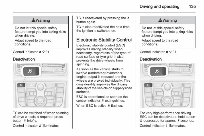
Driving and operating 135
9 Warning
Do not let this special safetyfeature tempt you into taking riskswhen driving.Adapt speed to the roadconditions.
Control indicator b 3 91.
Deactivation
TC can be switched off when spinningof drive wheels is required: pressbutton b briefly.Control indicator k illuminates.
TC is reactivated by pressing the bbutton again.TC is also reactivated the next timethe ignition is switched on.
Electronic Stability ControlElectronic stability control (ESC)improves driving stability whennecessary, regardless of the type ofroad surface or tyre grip. It alsoprevents the drive wheels fromspinning.As soon as the vehicle starts toswerve (understeer/oversteer),engine output is reduced and thewheels are braked individually. Thisconsiderably improves the drivingstability of the vehicle on slippery roadsurfaces.ESC is operational as soon as thecontrol indicator b extinguishes.When ESC is active b flashes.
9 Warning
Do not let this special safetyfeature tempt you into taking riskswhen driving.Adapt speed to the roadconditions.
Control indicator b 3 91.
Deactivation
For very high-performance drivingESC can be deactivated: hold buttonb depressed for approx. 7 seconds.Control indicator n illuminates.

136 Driving and operating
ESC is reactivated by pressing theb button again. If the TC system waspreviously disabled, both TC andESC are reactivated.ESC is also reactivated the next timethe ignition is switched on.
Cruise controlThe cruise control can store andmaintain speeds of approx. 30 to200 km/h. Deviations from the storedspeeds may occur when driving uphillor downhill.For safety reasons the cruise controlcannot be activated until the footbrake has been operated once.Activating in first gear is not possible.
Do not use the cruise control if it is notadvisable to maintain a constantspeed.
With automatic transmission, onlyactivate cruise control in automaticmode.Control indicator m 3 93.
Switching onPress rocker switch m at the upperend, control indicator m illuminateswhite.
ActivationAccelerate to the desired speed andturn thumb wheel to SET/-, thecurrent speed is stored andmaintained. Control indicator milluminates green. Accelerator pedalcan be released.Vehicle speed can be increased bydepressing the accelerator pedal.When the accelerator pedal isreleased, the previously stored speedis resumed.

Driving and operating 137
Increase speedWith cruise control active, hold thumbwheel turned to RES/+ or briefly turnto RES/+ repeatedly: speedincreases continuously or in smallincrements.Alternatively accelerate to the desiredspeed and store by turning to RES/+.
Reduce speedWith cruise control active, hold thumbwheel turned to SET/- or briefly turnto SET/- repeatedly: speeddecreases continuously or in smallincrements.
DeactivationPress button y, control indicator milluminates white. Cruise control isdeactivated.The stored speed ismemorised.Automatic deactivation:■ vehicle speed below approx.
30 km/h,■ the brake pedal is depressed,■ the clutch pedal is depressed,
■ selector lever in N,■ the Traction Control system or
electronic stability control isoperating.
Resume stored speedTurn thumb wheel to RES/+ ata speed above 30 km/h. The storedspeed will be obtained.
Switching offPress rocker switch m at the lowerend, control indicator m extinguishes.The stored speed is deleted.Switching off the ignition also deletesthe stored speed.
Object detectionsystemsParking assist
The parking assist makes parkingeasier by measuring the distancebetween the vehicle and obstacles,and giving acoustic signals. It is thedriver, however, who bears fullresponsibility for the parkingmanoeuvre.The system consists of four ultrasonicparking sensors in the rear bumper. Ifthe vehicle is equipped with a front

138 Driving and operating
parking assist the system consists offour additional ultrasonic parkingsensors in the front bumper.Control indicator r 3 91.
Activation
When reverse gear is engaged, thesystem is activated automatically.The front parking assist can also beactivated at a low speed by pressingthe r button.An illuminated LED in the parkingassist button indicates that thesystem is ready to operate.
An obstacle is indicated by a buzzingsound. The interval between thesounds becomes shorter as thevehicle gets closer to the obstacle.When the distance is less than30 cm, the buzzing is continuous.
DeactivationDeactivate the system by pressingthe r button.The LED in the button will go out andPark Assist Off will be displayed in theDriver Information Center.The system is deactivatedautomatically at a certain speed.
FaultIn the event of a fault in the system,r illuminates and a message isdisplayed in the Driver InformationCenter.Additionally, r illuminates ora vehicle message is displayed in theDriver Information Center ifa malfunction of the system due totemporary conditions like snowcovered sensors is detected.Vehicle messages 3 98.
Important hints for using theparking assist systems
9 Warning
Under certain circumstances,various reflective surfaces onobjects or clothing as well asexternal noise sources may causethe system to fail to detectobstacles.Special attention has to be paid tolow obstacles which can damagethe lower part of the bumper. Ifsuch obstacles leave the detectionarea of the sensors duringapproach of the vehicle,a continuous warning tone willsound.

Driving and operating 139
Caution
Performance of the sensor can bereduced when sensors arecovered, e.g. by ice or snow.Performance of the parking assistsystems can be reduced due toheavy loading.Special conditions apply if thereare taller vehicles involved (e.g.off-road vehicles, mini vans,vans). Object identification in theupper part of these vehiclescannot be guaranteed.Objects with a very small reflectioncross section, like objects ofnarrow size or soft materials, maynot be detected by the system.Parking assist will not avoida collision with objects which areout of the detection range of thesensors.
NoteThe parking assist systemautomatically detects factory-fittedtowing equipment. It is deactivatedwhen the connector is plugged in.The sensor may detect a non-existent object (echo disturbance)caused by external acoustic ormechanical disturbances.
FuelFuel for petrol enginesOnly use unleaded fuel that complieswith DIN EN 2281).Equivalent standardised fuels with anethanol content of max. 10 % byvolume may be used. In this case onlyuse fuel that complies withDIN 51625.Use fuel with the recommendedoctane rating 3 191. Use of fuel withtoo low an octane rating can reduceengine power and torque and slightlyincreases fuel consumption.
Caution
Use of fuel with too low an octanerating could lead to uncontrolledcombustion and engine damage.
1) Russia only: Usage of fuel with quality, not complying to the Technical Regulations in effect (Decree № 118 of 27.02.2008with amendments of 30.12.2008 № 1076) can lead to engine damage and loss of all warranty obligations.

140 Driving and operating
Fuel for diesel enginesOnly use diesel fuel that complieswith DIN EN 5902). The fuel musthave low sulphur content (max.10 ppm). Equivalent standardisedfuels with a biodiesel (= FAMEaccording to EN 14214) content ofmax. 7 % by volume (like DIN 51628or equivalent standards) may beused.Do not use marine diesel oils, heatingoils or entirely or partially plant-baseddiesel fuels, such as rape seed oil orbio diesel, Aquazole and similardiesel-water emulsions. Diesel fuelsmust not be diluted with fuels forpetrol engines.The flow and filterability of diesel fuelare temperature-dependent. Whentemperatures are low, refuel withdiesel fuel with guaranteed winterproperties.
Refuelling
9 Danger
Before refuelling, switch off engineand any external heaters withcombustion chambers. Switch offany mobile phones.Follow the operating and safetyinstructions of the filling stationwhen refuelling.
9 Danger
Fuel is flammable and explosive.No smoking. No naked flames orsparks.If you can smell fuel in yourvehicle, have the cause of thisremedied immediately bya workshop.
Caution
In case of misfuelling, do notswitch on ignition.
Fuel filler flap is located at right rearside of vehicle.
2) Russia only: Usage of fuel with quality, not complying to the Technical Regulations in effect (Decree № 118 of 27.02.2008with amendments of 30.12.2008 № 1076) can lead to engine damage and loss of all warranty obligations.

Driving and operating 141
The fuel filler flap can only be openedif the vehicle is unlocked. Pull flap atthe recess and open.
The fuel filler cap can be retained inthe bracket on the fuel filler flap.
Caution
Wipe off any overflowing fuelimmediately.
Fuel filler capOnly use genuine fuel filler caps.Diesel-engined vehicles have specialfuel filler caps.
Fuel consumption - CO2-EmissionsThe determination of fuelconsumption is regulated byEuropean directive715/2007 692/2008 A.The directive is oriented to actualdriving practices: Urban driving israted at approx. 1/3 and extra urbandriving with approx. 2/3. Cold startsand acceleration phases are alsotaken into consideration.
The specification of CO2 emission isalso a constituent of the directive.The figures given must not be takenas a guarantee for the actual fuelconsumption of a particular vehicle.Furthermore, fuel consumption isdependent on personal driving styleas well as road and traffic conditions.All values are based on the EU basemodel with standard equipment.The calculation of fuel consumptiontakes into account the vehicle’s kerbweight, ascertained in accordancewith the regulations. Optionalequipment may result in slightlyhigher fuel consumption andCO2 emission levels and a lowermaximum speed.Fuel consumption, CO2 emissions3 193.

142 Driving and operating
TowingGeneral informationOnly use towing equipment that hasbeen approved for your vehicle.Entrust retrofitting of towingequipment to a workshop. It may benecessary to make changes thataffect the cooling system, heatshields or other equipment.Fitting of towing equipment couldcover the opening of the towing eye.If this is the case use the coupling ballbar for towing. Always keep thecoupling ball bar in the vehicle.Installation dimensions of factory-fitted towing equipment 3 201.
Driving characteristics andtowing tipsBefore attaching a trailer, lubricatethe coupling ball. However, do not doso if a stabiliser, which acts on thecoupling ball, is being used to reducesnaking movements.
For trailers with low driving stabilityand caravan trailers with a permittedgross vehicle weight of more than1100 kg the use of a stabiliser isstrongly recommended when drivingabove 80 km/h.If the trailer starts snaking, drive moreslowly, do not attempt to correct thesteering and brake sharply ifnecessary.When driving downhill, drive in thesame gear as if driving uphill anddrive at a similar speed.Adjust tyre pressure to the valuespecified for full load 3 198.
Trailer towingTrailer loadsThe permissible trailer loads arevehicle and engine-dependentmaximum values which must not beexceeded. The actual trailer load isthe difference between the actualgross weight of the trailer and theactual coupling socket load with thetrailer coupled.
The permissible trailer loads arespecified in the vehicle documents. Ingeneral, they are valid for gradientsup to max. 12 %.The permitted trailer load applies upto the specified incline and up to analtitude of 1000 metres above sealevel. Since engine power decreasesas altitude increases due to the airbecoming thinner, therefore reducingclimbing ability, the permissible grosstrain weight also decreases by 10 %for every 1000 metres of additionalaltitude. The gross train weight doesnot have to be reduced when drivingon roads with slight inclines (less than8 %, e.g. motorways).The permissible gross train weightmust not be exceeded. This weight isspecified on the identification plate3 190.
Vertical coupling loadThe vertical coupling load is the loadexerted by the trailer on the couplingball. It can be varied by changing theweight distribution when loading thetrailer.

Driving and operating 143
The maximum permissible verticalcoupling load (75 kg) is specified onthe towing equipment identificationplate and in the vehicle documentsAlways aim for the maximum load,especially in the case of heavytrailers. The vertical coupling loadshould never fall below 25 kg.
Rear axle loadWhen the trailer is coupled and thetowing vehicle fully loaded, thepermissible rear axle load (seeidentification plate or vehicledocuments) may be exceeded by60 kg, the gross vehicle weight ratingmay be exceeded by 70 kg. If thepermissible rear axle load isexceeded, a maximum speed of100 km/h applies.
Towing equipment
Caution
When operating without a trailer,remove the coupling ball bar.
Stowage of the detachablecoupling ball bar
The bag with the coupling ball bar isstowed in the rear stowagecompartment on the floor.Stick the strap through the lashingeye and tighten the strap to securethe bag.
Fitting the detachable couplingball bar
Disengage and fold down the socket.Remove the sealing plug from theopening for the coupling ball bar andstow it.

144 Driving and operating
Checking the tensioning of thecoupling ball bar
■ Red marking on rotary knob mustpoint towards green marking oncoupling ball bar.
■ The gap between the rotary knoband the coupling ball bar must beapprox. 5 millimetres.
Otherwise, the coupling ball bar mustbe tensioned before being inserted:
Pull out rotary knob and turnclockwise as far as it will go.
Inserting the coupling ball bar
Insert the tensioned coupling ball barin the opening and push firmlyupwards until it audibly engages.The rotary handle snaps back into itsoriginal position resting against thecoupling ball bar without a gap.
9 Warning
Do not touch rotary handle duringinsertion.
Lock the coupling ball bar by turningthe key clockwise. Remove the keyand close the protective flap.

Driving and operating 145
Eye for break-away stopping cable
Attach breakaway stopping cable toeye.
Check that the coupling ball bar iscorrectly installed■ Green marking on rotary knob must
point towards green marking oncoupling ball bar.
■ There must be no gap between therotary handle and the coupling ballbar.
■ The coupling ball bar must be firmlyengaged in the opening.
■ The coupling ball bar must belocked and the key removed.
9 Warning
Towing a trailer is permitted onlywhen a coupling ball bar is fittedcorrectly. If the coupling ball bardoes not engage correctly, seekthe assistance of a workshop.
Dismounting the detachablecoupling ball bar
Open the protective flap and turn thekey clockwise to unlock the couplingball bar.Pull out rotary handle and turnclockwise as far as it will go. Pull outcoupling ball bar downwards.Insert sealing plug in opening. Foldaway socket.
Trailer stability assistIf the system detects snakingmovements, engine power is reducedand the vehicle/trailer combination isselectively braked until the snakingceases. While the system is working,keep steering wheel as still aspossible.Trailer stability assist (TSA) isa function of the electronic stabilitycontrol 3 135.

146 Vehicle care
Vehicle care
General Information ................... 146Vehicle checks ........................... 147Bulb replacement ....................... 152Electrical system ........................ 161Vehicle tools .............................. 167Wheels and tyres ....................... 168Jump starting ............................. 178Towing ....................................... 180Appearance care ....................... 182
General InformationAccessories and vehiclemodificationsWe recommend the use of genuineparts and accessories and factoryapproved parts specific for yourvehicle type. We cannot assess orguarantee reliability of other products- even if they have a regulatory orotherwise granted approval.Do not make any modifications to theelectrical system, e.g. changes ofelectronic control units (chip tuning).
Vehicle storageStorage for a long period of timeIf the vehicle is to be stored for severalmonths:■ Wash and wax the vehicle.■ Have the wax in the engine
compartment and underbodychecked.
■ Clean and preserve the rubberseals.
■ Change the engine oil.■ Drain the washer fluid reservoir.■ Check the coolant antifreeze and
corrosion protection.■ Adjust tyre pressure to the value
specified for full load.■ Park the vehicle in a dry, well
ventilated place. Engage first orreverse gear or set selector lever toP. Prevent the vehicle from rolling.
■ Do not apply the parking brake.■ Open the bonnet, close all doors
and lock the vehicle.■ Disconnect the clamp from the
negative terminal of the vehiclebattery. Beware that all systems arenot functional, e.g. anti-theft alarmsystem.
Putting back into operationWhen the vehicle is to be put back intooperation:■ Connect the clamp to the negative
terminal of the vehicle battery.Activate the electronics of thepower windows.
■ Check tyre pressure.

Vehicle care 147
■ Fill up the washer fluid reservoir.■ Check the engine oil level.■ Check the coolant level.■ Fit the number plate if necessary.
End-of-life vehiclerecoveryInformation on end-of-life vehiclerecovery centres and the recycling ofend-of-life vehicles is available on ourwebsite. Only entrust this work to anauthorised recycling centre.
Vehicle checksPerforming work
9 Warning
Only perform engine compartmentchecks when the ignition is off.The cooling fan may startoperating even if the ignition is off.
9 Danger
The ignition system usesextremely high voltage. Do nottouch.
BonnetOpening
Pull the release lever and return it toits original position.

148 Vehicle care
Press the safety catch and open thebonnet.
Secure the bonnet support.
ClosingBefore closing the bonnet, press thesupport into the holder.Lower the bonnet and allow it to dropinto the catch. Check that the bonnetis engaged.
Engine oilCheck the engine oil level manuallyon a regular basis to prevent damageto the engine.Ensure that the correct specificationof oil is used. Recommended fluidsand lubricants 3 186.Check with the vehicle on a levelsurface. The engine must be atoperating temperature and switchedoff for at least 5 minutes.Pull out the dipstick, wipe it clean,insert it to the stop on the handle, pullout and read the engine oil level.Insert dipstick to the stop on thehandle and make half a turn.
Different dipsticks are useddepending on engine variant.
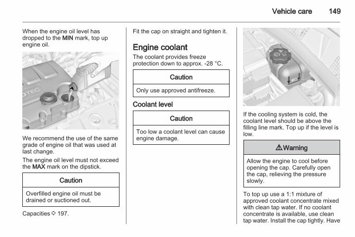
Vehicle care 149
When the engine oil level hasdropped to the MIN mark, top upengine oil.
We recommend the use of the samegrade of engine oil that was used atlast change.The engine oil level must not exceedthe MAX mark on the dipstick.
Caution
Overfilled engine oil must bedrained or suctioned out.
Capacities 3 197.
Fit the cap on straight and tighten it.
Engine coolantThe coolant provides freezeprotection down to approx. -28 °C.
Caution
Only use approved antifreeze.
Coolant level
Caution
Too low a coolant level can causeengine damage.
If the cooling system is cold, thecoolant level should be above thefilling line mark. Top up if the level islow.
9 Warning
Allow the engine to cool beforeopening the cap. Carefully openthe cap, relieving the pressureslowly.
To top up use a 1:1 mixture ofapproved coolant concentrate mixedwith clean tap water. If no coolantconcentrate is available, use cleantap water. Install the cap tightly. Have

150 Vehicle care
the coolant concentration checkedand have the cause of the coolantloss remedied by a workshop.
Washer fluid
Fill with clean water mixed witha suitable quantity of washer fluidwhich contains antifreeze. For thecorrect mixing ratio refer to thewasher fluid container.
Caution
Only washer fluid with a sufficientantifreeze concentration providesprotection at low temperatures ora sudden drop in temperature.
BrakesIn the event of minimum thickness ofthe brake lining, g illuminates.Additionally a code number ora vehicle message is displayed in theDriver Information Center. Vehiclemessages 3 98.Continued driving is possible buthave the brake lining replaced assoon as possible.Once new brake linings are installed,do not brake unnecessarily hard forthe first few journeys.
Brake fluid
9 Warning
Brake fluid is poisonous andcorrosive. Avoid contact with eyes,skin, fabrics and painted surfaces.
The brake fluid level must be betweenthe MIN and the MAX marks.When topping up, ensure maximumcleanliness as contamination of thebrake fluid can lead to brake systemmalfunctions. Have the cause of theloss of brake fluid remedied bya workshop.

Vehicle care 151
Only use high-performance brakefluid approved for the vehicle.Brake and clutch fluid 3 186.
BatteryThe vehicle battery is maintenance-free provided that the driving profileallows sufficient charging of thebattery. Short-distance-driving andfrequent engine starts can dischargethe battery. Avoid the use ofunnecessary electrical consumers.
Batteries do not belong in householdwaste. They must be disposed of atan appropriate recycling collectionpoint.Laying up the vehicle for more than4 weeks can lead to batterydischarge. Disconnect the clamp fromthe negative terminal of the vehiclebattery.
Ensure the ignition is switched offbefore connecting or disconnectingthe vehicle battery.Battery discharge protection 3 115.
Exchanging a battery
9 Warning
When fitting a battery with a lengthdeviating from the original one, itis essential to ensure a properfitting of the buffer element.
We recommend consultinga workshop.
Diesel fuel systembleedingIf the tank has been run dry, the dieselfuel system must be bled. Switch onthe ignition three times for15 seconds at a time. Then start theengine for a maximum of40 seconds. Repeat this process afterno less than 5 seconds. If the enginefails to start, seek the assistance ofa workshop.
Wiper blade replacementWiper blades on the windscreen

152 Vehicle care
Lift the wiper arm, press button todisengage the wiper blade andremove.Attach the wiper blade slighty angledto the wiper arm and push until itengages.Lower wiper arm carefully.
Wiper blade on the rear window
Lift wiper arm. Disengage wiper bladeas shown in illustration and remove.Attach the wiper blade slighty angledto the wiper arm and push until itengages.Lower wiper arm carefully.
Bulb replacementSwitch off the ignition and switch offthe relevant switch or close the doors.Only hold a new bulb at the base! Donot touch the bulb glass with barehands.Use only the same bulb type forreplacement.Replace headlight bulbs from withinthe engine compartment.
Halogen headlights
Headlights have separate systems forlow beam 1 (outer bulbs) and highbeam 2 (inner bulbs).
Low beam
1. Rotate the cap 1 anticlockwiseand remove it.

Vehicle care 153
2. Push the bulb holder upwards andwithdraw the bulb holder from thereflector.
3. Detach the bulb from the bulbholder and replace the bulb.
4. Insert the bulb holder into thereflector.
5. Fit the cap and rotate clockwise.
High beam
1. Rotate the cap 2 anticlockwiseand remove it.
2. Detach the plug from the bulb.
3. Disengage the spring clip andthen swivel it backwards.
4. Remove and replace the bulb.

154 Vehicle care
5. Swivel the spring clip forwardsand engage.
6. Attach the plug to the bulb.7. Fit the cap and rotate clockwise.
Sidelight/Daytime running light
1. Rotate the bulb holderanticlockwise and remove it.
2. Detach bulb from the bulb holderand replace it.
3. Insert the bulb holder into thereflector and rotate clockwise.
Front turn signal
1. Rotate the bulb holderanticlockwise and remove it.

Vehicle care 155
2. Rotate bulb anticlockwise andremove from bulb holder.
3. Replace bulb.4. Insert the bulb holder into the
reflector and rotate clockwise.
Adaptive forward lighting
Headlights have separate systems forlow beam and high beam 1 (outerbulbs) and additional high beam 2(inner bulbs). The cornering light isalso located behind the cover for theadditional high beam.
Low beam/High beam
1. Rotate the cap 1 anticlockwiseand remove it.
2. Push the bulb holder downwardsand withdraw the bulb holder fromthe reflector.
3. Detach the bulb from the bulbholder and replace the bulb.
4. Insert the bulb holder into thereflector.
5. Fit the cap and rotate clockwise.
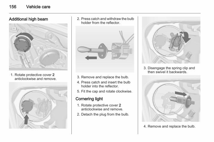
156 Vehicle care
Additional high beam
1. Rotate protective cover 2anticlockwise and remove.
2. Press catch and withdraw the bulbholder from the reflector.
3. Remove and replace the bulb.4. Press catch and insert the bulb
holder into the reflector.5. Fit the cap and rotate clockwise.
Cornering light1. Rotate protective cover 2
anticlockwise and remove.2. Detach the plug from the bulb.
3. Disengage the spring clip andthen swivel it backwards.
4. Remove and replace the bulb.

Vehicle care 157
5. Swivel the spring clip forwardsand engage.
6. Attach the plug to the bulb.7. Fit the cap and rotate clockwise.
Fog lights
The bulbs are accessible from theunderside of the vehicle.
1. Turn the bulb holder anticlockwiseand remove it from the reflector.
2. Disengage the bulb holder fromthe plug connector by pressingthe retaining lug.
3. Remove and replace the bulbholder with bulb.
4. Attach the plug connector.5. Insert the bulb holder into the
reflector.6. Turn the bulb holder clockwise
and engage.
Tail lights
1. Release the cover and remove it.

158 Vehicle care
2. Unscrew the two plastic securingnuts from the inside by hand.
3. Carefully withdraw the lightassembly from retaining pins andremove. Make sure that the cableduct remains in position.
4. Detach the wiring plug from thebulb carrier.
5. Unlatch the four retaining lugs andremove the bulb carrier.
6. Remove and replace the bulb.Tail light and brake light (1)Tail light (2)Turn signal light (3)
7. Insert the bulb carrier into the taillight assembly. Connect thewiring plug. Fit light assemblyonto retaining pins and tighten thesecuring nuts. Close the coverand engage.
8. Switch on the ignition, operateand check all lights.

Vehicle care 159
Tail lights in the tailgate frame
1. Open the tailgate and remove thecover with a screwdriver.
2. Press the retaining lug andremove the bulb carrierdownwards.
3. To replace the reverse light bulb(1), remove and replace the bulbTo replace the tail light bulb (2),push the bulb slightly into thesocket, rotate anticlockwise,remove and replace the bulb.
4. Insert the bulb carrier into theretainer.
5. Attach the cover.6. Switch on the ignition, operate
and check all lights.
For replacing the tail light bulb andrear fog light bulb on the right side ofthe tailgate frame, proceed in thesame way.
Side turn signal lightsHave bulbs replaced by a workshop.
Number plate light
1. Insert screwdriver in recess of thecover, press to the side andrelease spring.Remove cover.
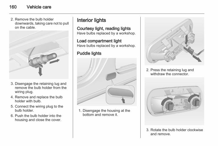
160 Vehicle care
2. Remove the bulb holderdownwards, taking care not to pullon the cable.
3. Disengage the retaining lug andremove the bulb holder from thewiring plug.
4. Remove and replace the bulbholder with bulb.
5. Connect the wiring plug to thebulb holder.
6. Push the bulb holder into thehousing and close the cover.
Interior lightsCourtesy light, reading lightsHave bulbs replaced by a workshop.
Load compartment lightHave bulbs replaced by a workshop.
Puddle lights
1. Disengage the housing at thebottom and remove it.
2. Press the retaining lug andwithdraw the connector.
3. Rotate the bulb holder clockwiseand remove.

Vehicle care 161
4. Pull the bulb out of the bulb holderand replace it.
5. Insert the bulb holder into thehousing and turn it anticlockwise.
6. Plug in the connector.7. Attach the housing.
Instrument panelilluminationHave bulbs replaced by a workshop.
Electrical systemFusesData on the replacement fuse mustmatch the data on the defective fuse.There are three fuse boxes in thevehicle:■ in the front left of the engine
compartment,■ in the interior behind the storage
compartment, or, in right-handdrive vehicles, behind theglovebox,
■ behind a cover on the left side of theload compartment.
Before replacing a fuse, turn off therespective switch and the ignition.A blown fuse can be recognized by itsmelted wire. Do not replace the fuseuntil the cause of the fault has beenremedied.Some functions are protected byseveral fuses.Fuses may also be inserted withoutexistence of a function.
Fuse extractorA fuse extractor may be located in thefuse box in the engine compartment.

162 Vehicle care
Place the fuse extractor on thevarious types of fuse from the top orside, and withdraw fuse.
Engine compartment fusebox
The fuse box is in the front left of theengine compartment.Disengage the cover, lift it upwardsand remove.After having changed defective fusesclose the fuse box cover and pressuntil it engages.If the fuse box cover is not closedcorrectly, malfunctions may occur.

Vehicle care 163
No. Circuit
1 Starter
2 –
3 Fuel filter, cooling
4 Horn
5 Terminal 30
6 Engine control module,transmission control unit
7 Fog light
8 Engine cooling
9 Engine cooling
10 Vacuum pump
11 Ignition, preheating
12 Headlamp levelling
13 Air conditioning system,terminal 15
14 Transmission control unit
15 High beam right
No. Circuit
16 High beam left
17 Engine control module
18 Engine control module,terminal 15
19 Airbag
20 Engine control module
21 Engine control module,terminal 87

164 Vehicle care
No. Circuit
22 Electrical parking brake
23 Tyre repair kit
No. Circuit
24 Fuel pump
25 ABS
26 Heated rear window
27 ABS
28 Interior fan
29 Cigarette lighter
30 Air conditioning system
31 Front power window, left
32 Front power window, right
33 Mirror heating
34 ABS
35 Airbag
Instrument panel fuse box
The fuse box is behind the storagecompartment in the instrument panel.Open compartment, compress thelocking tabs, fold compartment downand remove.

Vehicle care 165
In right-hand drive vehicles, the fusebox is located behind a cover in theglovebox. Open the glovebox, pullcover upwards and remove.
No. Circuit
1 Rear left door unlocking
2 Display, instrument, telephone
3 Radio
4 Ignition switch, immobiliser
5 Windscreen washer, rearscreen washer
6 Central locking system, tailgate
7 Central locking system
8 Rear right door unlocking
9 Courtesy light
No. Circuit
10 Heated steering wheel
11 –
12 –
13 Rain sensor, interior mirror,outside mirrors
14 –
Load compartment fusebox

166 Vehicle care
The fuse box is on the left side of theload compartment behind a cover.Remove the cover.
Disengage the four retaining lugs andremove the cover.
No. Circuit
1 Adaptive forward lighting
2 –
3 –
4 –
5 –
6 Rear power window, right
7 Adaptive forward lighting
8 Trailer module, Trailer socket
9 Seat, lumbar support, left
10 Rear power window, left
11 Park assist
12 Electrical sunblind
13 –
14 Heated front seats
15 Trailer module
16 Seat, lumbar support, right
17 –

Vehicle care 167
Vehicle toolsToolsVehicles with spare wheel
The jack and the vehicle tools are inthe spare wheel well in the loadcompartment.
Vehicles with tyre repair kit
To open the compartment, disengagethe cover and open it.
The vehicle tools are in the right-handcompartment in the loadcompartment, together with the tyrerepair kit.

168 Vehicle care
Wheels and tyres
Tyre condition, wheel conditionDrive over edges slowly and at rightangles if possible. Driving over sharpedges can cause tyre and wheeldamage. Do not trap tyres on the kerbwhen parking.Regularly check the wheels fordamage. Seek the assistance ofa workshop in the event of damage orunusual wear.
Winter tyresWinter tyres improve driving safety attemperatures below 7 °C and shouldtherefore be fitted on all wheels.In accordance with country-specificregulations, affix the speed sticker inthe driver's field of view.
Tyre designationsE.g. 195/65 R 15 91 H195 = Tyre width, mm65 = Cross-section ratio (tyre
height to tyre width), %R = Belt type: RadialRF = Type: RunFlat15 = Wheel diameter, inches91 = Load index e.g. 91 is
equivalent to 615 kgH = Speed code letter
Speed code letter:Q = up to 160 km/hS = up to 180 km/hT = up to 190 km/hH = up to 210 km/hV = up to 240 km/hW = up to 270 km/h
Tyre pressureCheck the pressure of cold tyres atleast every 14 days and before anylong journey. Do not forget the sparewheel. This also applies to vehicleswith tyre pressure monitoring system.Unscrew the valve cap.
Tyre pressure 3 198 and on the labelat the front passenger door.The tyre pressure data refers to coldtyres. It applies to summer and wintertyres.Always inflate the spare tyre to thepressure specified for full load.The ECO tyre pressure serves toachieve the smallest amount of fuelconsumption possible.Incorrect tyre pressures will impairsafety, vehicle handling, comfort andfuel economy and will increase tyrewear.

Vehicle care 169
9 Warning
If the pressure is too low, this canresult in considerable tyre warm-up and internal damage, leading totread separation and even to tyreblow-out at high speeds.
If the tyre pressure must be reducedor increased on a vehicle with tyrepressure monitoring system, switchoff ignition.
Tyre deflation detectionsystemThe tyre deflation detection systemcontinually checks the rotation speedof all four tyres.If a tyre loses pressure the controlindicator w illuminates yellow anda warning message is displayed in theDriver Information Center withUplevel-Display. Stop immediatelyand check tyre pressure.Control indicator w 3 92.
System initialisation
After tyre pressure correction orwheel change, the system must beinitiated: Switch on the ignition, pressand hold the DDS button for approx.4 seconds.If the system is ready again,a message is displayed in the DriverInformation Center withUplevel-Display.
Tread depthCheck tread depth at regularintervals.
Tyres should be replaced for safetyreasons at a tread depth of 2-3 mm(4 mm for winter tyres).
The legally permissible minimumtread depth (1.6 mm) has beenreached when the tread has worndown as far as one of the tread wearindicators (TWI). Their position isindicated by markings on thesidewall.If there is more wear at the front thanthe rear, swap round front wheels andrear wheels periodically. Ensure thatthe direction of rotation of the wheelsis the same as before.

170 Vehicle care
Tyres age, even if they are not used.We recommend tyre replacementevery 6 years.
Changing tyre and wheelsizeIf tyres of a different size than thosefitted at the factory are used, it may benecessary to reprogramme thespeedometer as well as the nominaltyre pressure and make other vehiclemodifications.After converting to a different tyresize, have the label with tyrepressures replaced.
9 Warning
Use of unsuitable tyres or wheelsmay lead to accidents and willinvalidate the vehicle typeapproval.
Wheel coversWheel covers and tyres that arefactory approved for the respectivevehicle and comply with all of therelevant wheel and tyre combinationrequirements must be used.If the wheel covers and tyres used arenot factory approved, the tyres mustnot have a rim protection ridge.Wheel covers must not impair brakecooling.
9 Warning
Use of unsuitable tyres or wheelcovers could lead to suddenpressure loss and therebyaccidents.
Tyre chains
Tyre chains are only permitted on thefront wheels.Always use fine mesh chains that addno more than 10 mm to the tyre treadand the inboard sides (including chainlock).
9 Warning
Damage may lead to tyre blowout.
Tyre chains are just permitted ontyres of size 195/65 R 15,205/55 R 16 and 225/45 R 17.

Vehicle care 171
Tyre chains are not permitted on tyresof size 225/40 R 18.The use of tyre chains is not permittedon the temporary spare wheel.
Tyre repair kitMinor damage to the tyre tread can berepaired with the tyre repair kit.Do not remove foreign bodies fromthe tyres.Tyre damage exceeding 4 mm or thatis at the tyre's sidewall near the rimcannot be repaired with the tyre repairkit.
9 Warning
Do not drive faster than 80 km/h.Do not use for a lengthy period.Steering and handling may beaffected.
If you have a flat tyre:Apply the parking brake and engagefirst gear, reverse gear or P.
The tyre repair kit is in the stowagecompartment in the loadcompartment.
To open the compartment, disengagethe cover and open it.
1. Take the sealant bottle andbracket with air hose from theinsert.

172 Vehicle care
2. Detach air hose from bracket andscrew onto sealant bottleconnection.
3. Position the sealant bottle on thebracket. Make sure that the bottledoes not fall.
4. Unscrew valve cap from defectivetyre.
5. Screw tyre inflation hose to valve.6. Screw air hose onto compressor
connection.7. Switch on ignition.
To avoid discharging the battery,we recommend running theengine.
8. Press < button on thecompressor. The tyre is filled withsealant.
9. The compressor pressure gaugebriefly indicates up to 6 bar whilstthe sealant bottle is emptying(approx. 30 seconds). Then thepressure starts to drop.
10. All of the sealant is pumped intothe tyre. Then the tyre is inflated.
11. The prescribed tyre pressureshould be obtained within10 minutes. Tyre pressure3 198. When the correct pressureis obtained, switch off the

Vehicle care 173
compressor by pressing the <button again.If the prescribed tyre pressure isnot obtained within 10 minutes,remove the tyre repair kit. Movethe vehicle one tyre rotation.Reattach the tyre repair kit andcontinue the filling procedure for10 minutes. If the prescribed tyrepressure is still not obtained, thetyre is too badly damaged. Seekthe assistance of a workshop.Release excess tyre pressureusing the ] button.Do not run the compressor longerthan 10 minutes.
12. Push catch on bracket to removesealant bottle from bracket. Screwthe tyre inflation hose to the freeconnection of the sealant bottle.This prevents sealant fromescaping. Stow tyre repair kit inload compartment.
13. Remove any excess sealantusing a cloth.
14. Take the label indicatingmaximum permitted speed fromthe sealant bottle and affix in thedriver's field of view.
15. Continue driving immediately sothat sealant is evenly distributedin the tyre. After driving approx.10 km (but no more than10 minutes), stop and check tyrepressure. Screw compressor airhose directly onto tyre valve andcompressor when doing this.If tyre pressure is more than1.3 bar, set it to the correct value.Repeat the procedure until thereis no more loss of pressure.If the tyre pressure has fallenbelow 1.3 bar, the vehicle mustnot be used. Seek the assistanceof a workshop.
16. Stow away tyre repair kit in loadcompartment.
NoteThe driving characteristics of therepaired tyre is severely affected,therefore have this tyre replaced.If unusual noise is heard or thecompressor becomes hot, turncompressor off for at least30 minutes.The built-in safety valve opens ata pressure of 7 bar.Note the expiry date of the kit. Afterthis date its sealing capability is nolonger guaranteed. Pay attention tostorage information on sealantbottle.Replace the used sealant bottle.Dispose of the bottle as prescribedby applicable laws.The compressor and sealant can beused from approx. -30 °C.The adapters supplied can be usedto pump up other items e.g.footballs, air mattresses, inflatabledinghies etc. They are located on theunderside of the compressor. Toremove, screw on compressor airhose and withdraw adapter.

174 Vehicle care
Wheel changingSome vehicles are equipped witha tyre repair kit instead of a sparewheel 3 171.Make the following preparations andobserve the following information:■ Park the vehicle on a level, firm and
non-skid surface. The front wheelsmust be in the straight-aheadposition.
■ Apply the parking brake andengage first gear, reverse gear orP.
■ Remove the spare wheel 3 176.■ Never change more than one wheel
at once.■ Use the jack only to change wheels
in case of puncture, not forseasonal winter or summer tyrechange.
■ If the ground on which the vehicleis standing is soft, a solid board(max. 1 cm thick) should be placedunder the jack.
■ No people or animals may be in thevehicle when it is jacked-up.
■ Never crawl under a jacked-upvehicle.
■ Do not start the vehicle when it israised on the jack.
■ Before screwing in the wheel bolts,clean them and lightly coat thetaper of each wheel bolt withcommercially available grease.
1. Pull off the wheel cover with thehook. Vehicle tools 3 167.For wheel covers with visiblewheel bolts: The cover can remainon the wheel. Do not remove theretaining rings on the wheel bolts.
Alloy wheels: Disengage wheelbolt caps with a screwdriver andremove. To protect the wheel,place a soft cloth between thescrewdriver and the alloy wheel.
2. Install the wheel wrench ensuringthat it locates securely and looseneach wheel bolt by half a turn.

Vehicle care 175
3. Ensure the jack is positionedcorrectly with the vehicle jackingpoints.Lifting the vehicle onto a liftingplatform:
Position the rear arm of the liftingplatform at the underbody.
Position the front arm of the liftingplatform at the underbody.
4. Set the jack to the necessaryheight. Position it directly belowthe jacking point in a manner thatprevents it from slipping.

176 Vehicle care
Attach jack handle and with thejack correctly aligned rotatehandle until wheel is clear of theground.
5. Unscrew the wheel bolts.6. Change the wheel.7. Screw on the wheel bolts.8. Lower vehicle.9. Install the wheel wrench ensuring
that it locates securely and tighteneach bolt in a crosswisesequence. Tightening torque is110 Nm.
10. Align the valve hole in the wheelcover with the tyre valve beforeinstalling.Install wheel bolt caps.
11. Stow the replaced wheel 3 176and the vehicle tools 3 167.
12. Check the tyre pressure of theinstalled tyre and also the wheelbolt torque as soon as possible.
Have the defective tyre renewed orrepaired.
Spare wheelSome vehicles are equipped witha tyre repair kit instead of a sparewheel.The spare wheel can be classified asa temporary spare wheel dependingon the size compared to the othermounted wheels and countryregulations.The spare wheel has a steel rim.The use of a spare wheel that issmaller than the other wheels or incombination with winter tyres couldaffect driveability. Have the defectivetyre replaced as soon as possible.
The spare wheel is located in the loadcompartment beneath the floorcovering. It is secured with a wing nut.The spare wheel well is not designedfor all permissible tyre sizes. Ifa wheel wider than the spare wheelhas to be stowed in the loadcompartment, it needs to be securedwith a strap or, depending on theversion, with an extension bar.
Storing a replaced wheel in theload compartment using a strapUse the strap placed in the tool box.Vehicle tools 3 167.■ Position the wheel on the load
compartment floor close to one sidewall of the load compartment.

Vehicle care 177
■ Place the loop end of the strapthrough the front lashing eye of theaccording side.
■ Place the hook end of the strapthrough the loop and pull it until thestrap is fastened securely to thelashing eye.
■ Insert the strap through the spokesof the wheel as shown in theillustration.
■ Mount the hook to the rear lashingeye.
■ Tighten the strap and secure itusing the buckle.
Storing a replaced wheel in thespare wheel well using anextension barUse the extension bar placed in thetool box. Vehicle tools 3 167.■ Turn the wing nut anticlockwise and
remove temporary spare wheel.
■ Take the extension bar from thetool box and screw it on the bolt.
■ Store the damaged wheel andsecure it by turning the wing nutclockwise.
The floor cover can be placed on theprojecting wheel.Remove the extension bar beforefitting the spare wheel in the well afterrenewing or repairing the defectivewheel.

178 Vehicle care
9 Warning
Storing a jack, a wheel or otherequipment in the loadcompartment could cause injury ifthey are not fixed properly. Duringa sudden stop or a collision, looseequipment could strike someone.Store jack and tools always in therespective storage compartmentsand secure them by fixing.Place the damaged wheel alwaysin the load compartment securedby the strap or in the spare wheelwell secured by the wing nut.
Temporary spare wheelThe use of the temporary spare wheelcould affect driveability. Have thedefective tyre renewed or repaired assoon as possible.Only mount one temporary sparewheel. Do not drive faster than80 km/h. Take curves slowly. Do notuse for a long period of time.
If your vehicle gets a flat tyre in therear while towing another vehicle,mount the temporary spare wheel inthe front and the full tyre in the rear.Tyre chains 3 170.
Directional tyresFit directional tyres such that they rollin the direction of travel. The rollingdirection is indicated by a symbol(e.g. an arrow) on the sidewall.The following applies to tyres fittedopposing the rolling direction:■ Driveability may be affected. Have
the defective tyre renewed orrepaired as soon as possible.
■ Drive particularly carefully on wetand snow-covered road surfaces.
Jump startingDo not start with quick charger.A vehicle with a discharged batterycan be started using jump leads andthe battery of another vehicle.
9 Warning
Be extremely careful when startingwith jump leads. Any deviationfrom the following instructions canlead to injuries or damage causedby battery explosion or damage tothe electrical systems of bothvehicles.
9 Warning
Avoid contact of the battery witheyes, skin, fabrics and paintedsurfaces. The fluid containssulphuric acid which can causeinjuries and damage in the eventof direct contact.
■ Never expose the battery to nakedflames or sparks.

Vehicle care 179
■ A discharged battery can alreadyfreeze at a temperature of 0 °C.Defrost the frozen battery beforeconnecting jump leads.
■ Wear eye protection and protectiveclothing when handling a battery.
■ Use a booster battery with thesame voltage (12 volts). Its capacity(Ah) must not be much less thanthat of the discharged battery.
■ Use jump leads with insulatedterminals and a cross section of atleast 16 mm2 (25 mm2 for dieselengines).
■ Do not disconnect the dischargedbattery from the vehicle.
■ Switch off all unnecessary electricalconsumers.
■ Do not lean over the battery duringjump starting.
■ Do not allow the terminals of onelead to touch those of the otherlead.
■ The vehicles must not come intocontact with each other during thejump starting process.
■ Apply the parking brake,transmission in neutral, automatictransmission in P.
Lead connection order:1. Connect the red lead to the
positive terminal of the boosterbattery.
2. Connect the other end of the redlead to the positive terminal of thedischarged battery.
3. Connect the black lead to thenegative terminal of the boosterbattery.
4. Connect the other end of the blacklead to a vehicle grounding point,such as the engine block or anengine mounting bolt. Connect asfar away from the dischargedbattery as possible, however atleast 60 cm.
Route the leads so that they cannotcatch on rotating parts in the enginecompartment.To start the engine:1. Start the engine of the vehicle
providing the jump.2. After 5 minutes, start the other
engine. Start attempts should bemade for no longer than15 seconds at an interval of1 minute.
3. Allow both engines to idle forapprox. 3 minutes with the leadsconnected.
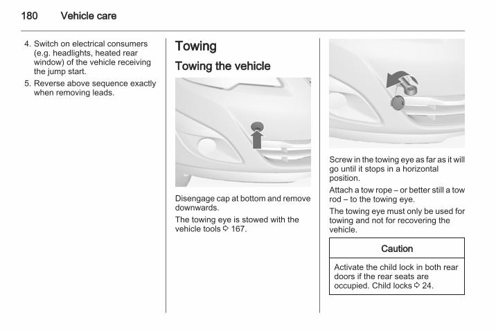
180 Vehicle care
4. Switch on electrical consumers(e.g. headlights, heated rearwindow) of the vehicle receivingthe jump start.
5. Reverse above sequence exactlywhen removing leads.
TowingTowing the vehicle
Disengage cap at bottom and removedownwards.The towing eye is stowed with thevehicle tools 3 167.
Screw in the towing eye as far as it willgo until it stops in a horizontalposition.Attach a tow rope – or better still a towrod – to the towing eye.The towing eye must only be used fortowing and not for recovering thevehicle.
Caution
Activate the child lock in both reardoors if the rear seats areoccupied. Child locks 3 24.

Vehicle care 181
Switch on ignition to release steeringwheel lock and to permit operation ofbrake lights, horn and windscreenwiper.Transmission in neutral.Switch on the hazard warningflashers on both vehicles.
Caution
Drive slowly. Do not drive jerkily.Excessive tractive force candamage the vehicle.
When the engine is not running,considerably more force is needed tobrake and steer.To prevent the entry of exhaust gasesfrom the towing vehicle, switch on theair recirculation and close thewindows.Vehicles with automatic transmission:The vehicle must be towed facingforwards, not faster than 80 km/h norfurther than 100 km. In all other casesand when the transmission isdefective, the front axle must beraised off the ground.
Seek the assistance of a workshop.After towing, unscrew the towing eye.Insert cap at the bottom and closecap.
Towing another vehicle
Disengage the cap at the bottom andremove downwards.The towing eye is stowed with thevehicle tools 3 167.
Screw in the towing eye as far as it willgo until it stops in a horizontalposition.The lashing eye at the rearunderneath the vehicle must never beused as a towing eye.Attach a tow rope – or even bettera tow bar – to the towing eye.The towing eye must only be used fortowing and not for recoveringa vehicle.Switch on the hazard warningflashers on both vehicles.

182 Vehicle care
Caution
Drive slowly. Do not drive jerkily.Excessive tractive force candamage the vehicle.
After towing, unscrew the towing eye.Insert cap at the bottom and engagecap.
Appearance careExterior careLocksThe locks are lubricated at the factoryusing a high quality lock cylindergrease. Use de-icing agent only whenabsolutely necessary, as this hasa degreasing effect and impairs lockfunction. After using de-icing agent,have the locks regreased bya workshop.
WashingThe paintwork of your vehicle isexposed to environmental influences.Wash and wax your vehicle regularly.When using automatic vehiclewashes, select a programme thatincludes waxing.Bird droppings, dead insects, resin,pollen and the like should be cleanedoff immediately, as they containaggressive constituents which cancause paint damage.
If using a vehicle wash, comply withthe vehicle wash manufacturer'sinstructions. The windscreen wipersand rear window wiper must beswitched off. Remove antenna andexternal accessories such as roofracks etc.If you wash your vehicle by hand,make sure that the insides of thewheel housings are also thoroughlyrinsed out.Clean edges and folds on openeddoors and the bonnet as well as theareas they cover.Have the door hinges of all doorsgreased by a workshop.Do not clean the engine compartmentwith a steam-jet or high-pressure jetcleaner.Thoroughly rinse and leather-off thevehicle. Rinse leather frequently. Useseparate leathers for painted andglass surfaces: remnants of wax onthe windows will impair vision.Do not use hard objects to removespots of tar. Use tar removal spray onpainted surfaces.

Vehicle care 183
Exterior lightsHeadlight and other light covers aremade of plastic. Do not use anyabrasive or caustic agents, do not usean ice scraper, and do not clean themdry.
Polishing and waxingWax the vehicle regularly (at thelatest when water no longer beads).Otherwise, the paintwork will dry out.Polishing is necessary only if the painthas become dull or if solid depositshave become attached to it.Paintwork polish with silicone formsa protective film, making waxingunnecessary.Plastic body parts must not be treatedwith wax or polishing agents.
Windows and windscreen wiperbladesUse a soft lint-free cloth or chamoisleather together with window cleanerand insect remover.When cleaning the rear window,make sure the heating element insideis not damaged.
For mechanical removal of ice, usea sharp-edged ice scraper. Press thescraper firmly against the glass sothat no dirt can get under it andscratch the glass.Clean smearing wiper blades witha soft cloth and window cleaner.
MoonroofNever clean with solvents or abrasiveagents, fuels, aggressive media (e.g.paint cleaner, acetone-containingsolutions etc.), acidic or highlyalkaline media or abrasive pads. Donot apply wax or polishing agents tothe middle part of the moonroof.
Wheels and tyresDo not use high-pressure jetcleaners.Clean rims with a pH-neutral wheelcleaner.Rims are painted and can be treatedwith the same agents as the body.
Paintwork damageRectify minor paintwork damage witha touch-up pen before rust forms.Have more extensive damage or rustareas repaired by a workshop.
UnderbodySome areas of the vehicle underbodyhave a PVC undercoating while othercritical areas have a durableprotective wax coating.After the underbody is washed, checkthe underbody and have it waxed ifnecessary.Bitumen/rubber materials coulddamage the PVC coating. Haveunderbody work carried out bya workshop.Before and after winter, wash theunderbody and have the protectivewax coating checked.
Towing equipmentDo not clean the coupling ball bar witha steam-jet or high-pressure jetcleaner.

184 Vehicle care
Rear carrier systemClean the rear carrier system witha steam-jet or high-pressure jetcleaner at least once a year.Operate the rear carrier system oncein a while if not in regular use, inparticular during winter.
Interior careInterior and upholsteryOnly clean the vehicle interior,including the instrument panel fasciaand panelling, with a dry cloth orinterior cleaner.Clean the leather upholstery withclear water and a soft cloth. In case ofheavy soiling, use leather care.The instrument panel should only becleaned using a soft damp cloth.Clean fabric upholstery witha vacuum cleaner and brush.Remove stains with an upholsterycleaner.Clean seat belts with lukewarm wateror interior cleaner.
Caution
Close Velcro fasteners as openVelcro fasteners on clothing coulddamage seat upholstery.The same applies to clothing withsharp-edged objects, like zips orbelts or studded jeans.
Plastic and rubber partsPlastic and rubber parts can becleaned with the same cleaner asused to clean the body. Use interiorcleaner if necessary. Do not use anyother agent. Avoid solvents and petrolin particular. Do not use high-pressure jet cleaners.

Service and maintenance 185
Service andmaintenance
General information ................... 185Recommended fluids, lubricantsand parts .................................... 186
General informationService informationIn order to ensure economical andsafe vehicle operation and tomaintain the value of your vehicle, itis of vital importance that allmaintenance work is carried out at theproper intervals as specified.The detailed, up-to-date serviceschedule for your vehicle is availableat the workshop.Service display 3 85.
European service intervalsMaintenance of your vehicle isrequired every 30,000 km or after1 year, whichever occurs first, unlessotherwise indicated in the servicedisplay.The European service intervals arevalid for the following countries:Andorra, Austria, Belgium, Bosnia-Herzegovina, Bulgaria, Croatia,Cyprus, Czech Republic, Denmark,Estonia, Finland, France, Germany,Greece, Greenland, Hungary,
Iceland, Ireland, Italy, Latvia,Lithuania, Luxembourg, Macedonia,Malta, Montenegro, Netherlands,Norway, Poland, Portugal, Romania,Serbia, Slovakia, Slovenia, Spain,Sweden, Switzerland, UnitedKingdom.Service display 3 85.
International service intervalsMaintenance of your vehicle isrequired every 15,000 km or after1 year, whichever occurs first, unlessotherwise indicated in the servicedisplay.The international service intervals arevalid for the countries which are notlisted in the European serviceintervals.Service display 3 85.
ConfirmationsConfirmation of service is recorded inthe Service and Warranty Booklet.The date and mileage is completedwith the stamp and signature of theservicing workshop.

186 Service and maintenance
Make sure that the Service andWarranty Booklet is completedcorrectly as continuous proof ofservice is essential if any warranty orgoodwill claims are to be met, and isalso a benefit when selling thevehicle.
Service interval with remainingengine oil life durationThe service interval is based onseveral parameters depending onusage.The service display lets you knowwhen to change the engine oil.Service display 3 85.
Recommended fluids,lubricants and partsRecommended fluids andlubricantsOnly use products that have beentested and approved. Damageresulting from the use of non-approved materials will not becovered by the warranty.
9 Warning
Operating materials arehazardous and could bepoisonous. Handle with care. Payattention to information given onthe containers.
Engine oilEngine oil is identified by its qualityand its viscosity. Quality is moreimportant than viscosity whenselecting which engine oil to use. Theoil quality ensures e.g. enginecleanliness, wear protection and oil
aging control, whereas viscositygrade gives information on the oil'sthickness over a temperature range.The new engine oil qualityDexos 2 TM is the newest oil qualityand combines gasoline and dieselperformance. If it is unavailable,engine oils of other listed qualitieshave to be used.
Engine oil quality for Europeanservice schedulesDexos 2 TM = All petrol and diesel
engines
Alternative qualities if Dexos 2 TM isnot available:GM-LL-A-025 = Petrol enginesGM-LL-B-025 = Diesel engines
Engine oil quality for internationalservice schedulesDexos 2 TM = All petrol and diesel
engines
Alternative qualities if Dexos 2 TM isnot available:GM-LL-A-025 = Petrol enginesGM-LL-B-025 = Diesel engines

Service and maintenance 187
Alternative qualities if GM-LL-A-025or GM-LL-B-025 are not available:ACEA-A3/B3 orA3/B4
= Petrol engines
ACEA-A3/B4 = Diesel engineswithout DieselParticle Filter(DPF)
ACEA-C3 = Diesel engineswith DPF
Topping up engine oilEngine oils of different manufacturersand brands can be mixed as long asthey comply with the required engineoil quality and viscosity.If engine oil of the required quality isnot available, a maximum of 1 litre ofACEA C3 grade may be used (onlyonce between each oil change). Theviscosity should be of one of thebelow listed viscosity grades.Use of engine oil with onlyACEA A1/B1 or only A5/B5 quality isprohibited, since it can cause long-term engine damage under certainoperating conditions.
Additional engine oil additivesThe use of additional engine oiladditives could cause damage andinvalidate the warranty.
Engine oil viscosity gradesUse only engine oil viscosity gradesSAE 5W-30 or 5W-40, 0W-30 or0W-40.The SAE viscosity grade givesinformation of the thickness of the oil.Multigrade oil is indicated by twofigures. The first figure, followed bya W, indicates the low temperatureviscosity and the second figure thehigh temperature viscosity.Select the approriate viscosity gradedepending on the minimum ambienttemperature. All of the recommendedviscosity grades are suitable for highambient temperatures.■ down to -25°C:
SAE 5W-30 or SAE 5W-40■ below -25°C:
SAE 0W-30 or SAE 0W-40
Coolant and antifreezeUse only silicate-free long life coolant(LLC) antifreeze.The system is factory filled withcoolant designed for excellentcorrosion protection and frostprotection down to approx. -28 °C.This concentration should bemaintained all year round. The use ofadditional coolant additives thatintend to give additional corrosionprotection or seal against minor leakscan cause function problems. Liabilityfor consequences resulting from theuse of additional coolant additives willbe rejected.
Brake and clutch fluidOnly use high-performance brakefluid approved for the vehicle, consultyour workshop.Over time, brake fluid absorbsmoisture which will reduce brakingeffectiveness. The brake fluid shouldtherefore be replaced at the specifiedinterval.

188 Service and maintenance
Brake fluid should be stored ina sealed container to avoid waterabsorption.Ensure brake fluid does not becomecontaminated.

Technical data 189
Technical data
Vehicle identification .................. 189Vehicle data ............................... 191
Vehicle identificationVehicle IdentificationNumber
The Vehicle Identification Number isstamped on the identification plateand on the floor pan, under the floorcovering, visible under a cover.
The Vehicle Identification Numbermay be embossed on the instrumentpanel visible through the windscreen.

190 Technical data
Identification plate
The identification plate is located onthe rear right-hand door frame.
Information on identification label:1 = Manufacturer2 = Type approval number3 = Vehicle Identification Number4 = Permissible gross vehicle
weight rating5 = Permissible gross train weight6 = Maximum permissible front axle
load7 = Maximum permissible rear axle
load8 = Vehicle-specific or country
specific data
The combined total of front and rearaxle loads must not exceed thepermissible gross vehicle weight. Forexample, if the front axle is bearing itsmaximum permissible load, the rearaxle can only bear a load that is equalto the gross vehicle weight minus thefront axle load.The technical data is determined inaccordance with EuropeanCommunity standards. We reservethe right to make modifications.Specifications in the vehicledocuments always have priority overthose given in this manual.
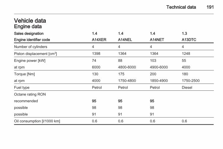
Technical data 191
Vehicle dataEngine dataSales designation 1.4 1.4 1.4 1.3Engine identifier code A14XER A14NEL A14NET A13DTC
Number of cylinders 4 4 4 4
Piston displacement [cm3] 1398 1364 1364 1248
Engine power [kW] 74 88 103 55
at rpm 6000 4800-6000 4900-6000 4000
Torque [Nm] 130 175 200 180
at rpm 4000 1750-4800 1850-4900 1750-2500
Fuel type Petrol Petrol Petrol Diesel
Octane rating RON
recommended 95 95 95
possible 98 98 98
possible 91 91 91
Oil consumption [l/1000 km] 0.6 0.6 0.6 0.6

192 Technical data
Sales designation 1.3 1.7 1.7 1.7Engine identifier code A13DTE A17DT A17DTC A17DTS
Number of cylinders 4 4 4 4
Piston displacement [cm3] 1248 1686 1686 1686
Engine power [kW] 70 74 81 96
at rpm 4000 4000 4000 4000
Torque [Nm] 180 260 280 300
at rpm 1750-2500 1700-2550 1700-2500 1700-2500
Fuel type Diesel Diesel Diesel Diesel
Oil consumption [l/1000 km] 0.6 0.6 0.6 0.6
PerformanceEngine A14XER A14NEL A14NET A13DTC
Maximum speed1) [km/h]
Manual transmission 177 188 196 160
Automatic transmission – – – –
1) The maximum speed indicated is achievable at kerb weight (without driver) plus 200 kg payload. Optional equipmentcould reduce the specified maximum speed of the vehicle.

Technical data 193
Engine A13DTE A17DT A17DTC A17DTS
Maximum speed2) [km/h]
Manual transmission 3) – 3) 3)
Automatic transmission – 172 – –
Fuel consumption - CO2-emissionsManual transmission / automatic transmission.
Engine A14XER A14NEL A14NET A13DTC
urban [l/100 km] 7.9/– 8.0/– 8.8/– 5.9/–
extra-urban [l/100 km] 5.1/– 5.0/– 5.4/– 4.3/–
total [l/100 km] 6.1/– 6.1/– 6.7/– 4.9/–
CO2 [g/km] 144/– 143/– 156/– 129/–
2) The maximum speed indicated is achievable at kerb weight (without driver) plus 200 kg payload. Optional equipmentcould reduce the specified maximum speed of the vehicle.
3) Value was not available at time of printing.

194 Technical data
Engine A13DTE A17DT A17DTC A17DTS
urban [l/100 km] 4)/– –/8.6 4)/– 4)/–
extra-urban [l/100 km] 4)/– –/5.1 4)/– 4)/–
total [l/100 km] 4)/– –/6.4 4)/– 4)/–
CO2 [g/km] 4)/– –/168 4)/– 4)/–
4) Value was not available at time of printing.

Technical data 195
Vehicle weightKerb weight, basic model without any optional equipment
Engine Manual transmission Automatic transmission
without/with air conditioning[kg]
A14XER 1360/1375 –
A14NEL 1393/1408 –
A14NET 1393/1408 –
A13DTC 1437/1452 –
A13DTE 1393/1408 –
A17DT – 1503/1518
A17DTC 1503/1518 1503/1518
A17DTS 1503/1518 –

196 Technical data
Kerb weight, basic model with all optional equipmentEngine Manual transmission Automatic transmission
without/with air conditioning[kg]
A14XER –/1571 –
A14NEL –/1613 –
A14NET –/1613 –
A13DTC –/1613 –
A13DTE –/1471 –
A17DT – –/1701
A17DTC –/1664 –/1701
A17DTS –/1664 –
Vehicle dimensions
Length [mm] 4288
Width without exterior mirrors [mm] 1812
Width with two exterior mirrors [mm] 1992
Height (without antenna) [mm] 1615
Length of load compartment floor [mm] 815

Technical data 197
Length of load compartment with folded rear seats [mm] 1642
Load compartment width [mm] 1038
Load compartment height [mm] 803
Height of load compartment opening 791
Wheelbase [mm] 2644
Turning circle diameter [m] 11.1
CapacitiesEngine oilEngine A14XER A14NEL A14NET A13DTC
including Filter [l] 4.0 4.0 4.0 3.2
between MIN and MAX [l] 1.0 1.0 1.0 1.0
Engine A13DTE A17DT A17DTC A17DTS
including Filter [l] 3.2 5.4 5.4 5.4
between MIN and MAX [l] 1.0 1.0 1.0 1.0

198 Technical data
Fuel tankPetrol/diesel, nominal capacity [l] 54
Tyre pressuresComfort with up to 3 people ECO with up to 3 people With full load
Engine Tyres front rear front rear front rear[kPa/bar]([psi])
[kPa/bar]([psi])
[kPa/bar]([psi])
[kPa/bar]([psi])
[kPa/bar]([psi])
[kPa/bar]([psi])
A14XER 195/65 R15, 230/2.3 (33) 210/2.1 (30) 280/2.8 (41) 260/2.6 (38) 250/2.5 (36) 320/3.2 (46)
205/55 R16,
225/45 R17
225/40 R185) 230/2.3 (33) 210/2.1 (30) – – 250/2.5 (36) 320/3.2 (46)
A14NEL 195/65 R15, 230/2.3 (33) 210/2.1 (30) 280/2.8 (41) 260/2.6 (38) 250/2.5 (36) 320/3.2 (46)
205/55 R16,
225/45 R17
225/40 R185) 250/2.5 (36) 230/2.3 (33) – – 270/2.7 (39) 320/3.2 (46)
5) With reduced steering angle.

Technical data 199
Comfort with up to 3 people ECO with up to 3 people With full loadEngine Tyres front rear front rear front rear
[kPa/bar]([psi])
[kPa/bar]([psi])
[kPa/bar]([psi])
[kPa/bar]([psi])
[kPa/bar]([psi])
[kPa/bar]([psi])
A14NET 205/55 R16, 230/2.3 (33) 210/2.1 (30) 280/2.8 (41) 260/2.6 (38) 250/2.5 (36) 320/3.2 (46)
225/45 R17
225/40 R185) 250/2.5 (36) 230/2.3 (33) – – 270/2.7 (39) 320/3.2 (46)
A13DTC 195/65 R15, 230/2.3 (33) 210/2.1 (30) 280/2.8 (41) 260/2.6 (38) 250/2.5 (36) 320/3.2 (46)
205/55 R16,
225/45 R17
225/40 R185) 230/2.3 (33) 210/2.1 (30) – – 250/2.5 (36) 320/3.2 (46)
A13DTE 195/65 R15, 230/2.3 (33) 210/2.1 (30) 280/2.8 (41) 260/2.6 (38) 250/2.5 (36) 320/3.2 (46)
205/55 R16,
225/45 R17
225/40 R185) 230/2.3 (33) 210/2.1 (30) – – 250/2.5 (36) 320/3.2 (46)
5) With reduced steering angle.

200 Technical data
Comfort with up to 3 people ECO with up to 3 people With full loadEngine Tyres front rear front rear front rear
[kPa/bar]([psi])
[kPa/bar]([psi])
[kPa/bar]([psi])
[kPa/bar]([psi])
[kPa/bar]([psi])
[kPa/bar]([psi])
A17DT,A17DTC,A17DTS
195/65 R156), 250/2.5 (36) 230/2.3 (33) 300/3.0 (43) 280/2.8 (41) 270/2.7 (39) 320/3.2 (46)
205/55 R16,
225/45 R17
225/40 R185) 270/2.7 (39) 250/2.5 (36) – – 280/2.8 (41) 320/3.2 (46)
All Temporary sparewheel
420/4.2 (61) 420/4.2 (61) – – 420/4.2 (61) 420/4.2 (61)
6) Only permitted in combination with weight reduction package.5) With reduced steering angle.

Technical data 201
Towing hitch installation dimensions

202 Customer information
Customer information
Vehicle data recording andprivacy ....................................... 202
Vehicle data recordingand privacyEvent data recordersThe vehicle has a number ofsophisticated systems that monitorand control several vehicle data.Some data may be stored duringregular operation to facilitate repair ofdetected malfunctions, other data isstored only in a crash or near crashevent by systems commonly calledevent data recorders (EDR).The systems may record data aboutthe condition of the vehicle and how itwas operated (e.g. engine speed,brake application, seat belt usage).To read this data special equipmentand access to the vehicle is required.This will take place when the vehicleis serviced in a workshop. Some datais electronically fed into GM globaldiagnostic systems. Themanufacturer will not accessinformation about a crash event orshare it with others except
■ with the consent of the vehicleowner or, if the vehicle is leased,with the consent of the lessee,
■ in response to an official request ofpolice or similar government office,
■ as part of the manufacturer’sdefense in case of legalproceedings,
■ as required by law.In addition, the manufacturer may usethe collected or received data■ for the manufacturer's research
needs,■ to make it available for research
needs where appropriateconfidentiality is maintained andneed is shown,
■ to share summary data which is nottied to a specific vehicle with otherorganisations for researchpurposes.

Customer information 203

204
Index AAccessories and vehicle
modifications .......................... 146Adaptive brake light.................... 132Adaptive forward lighting ..........
.................................. 93, 110, 155Adjustable air vents ................... 121Airbag and belt tensioners ........... 88Airbag deactivation ................ 49, 89Airbag system .............................. 47Air conditioning regular
operation ................................ 122Air conditioning system .............. 117Air intake .................................... 122Air quality sensor........................ 118Alert............................................ 100Antifreeze................................... 149Antilock brake system ................ 132Antilock brake system (ABS) ....... 90Anti-theft alarm system ................ 27Anti-theft locking system .............. 26Armrest................................... 38, 42Armrest storage ........................... 60Ashtrays ....................................... 83Automatic anti-dazzle .................. 29Automatic light control ............... 108Automatic locking .................. 24, 93Automatic transmission ............. 128Auxiliary heater........................... 121
BBattery ....................................... 151Battery discharge protection ...... 115Battery, jump starting.................. 178Belts.............................................. 43Bicycle rack.................................. 60Bonnet ....................................... 147Brake and clutch fluid................. 186Brake and clutch system ............. 89Brake assist ............................... 134Brake fluid .................................. 150Brakes ............................... 132, 150Bulb replacement ....................... 152
CCapacities .................................. 197Car Pass ...................................... 19Catalytic converter ..................... 128Central locking system ................ 21Centre console lighting .............. 114Changing tyre and wheel size . . . 170Charging system .......................... 89Child locks ................................... 24Child restraint installation
locations ................................... 53Child restraint systems ................ 51Cigarette lighter ........................... 83Cleaning the vehicle................... 182Climate control ............................. 16
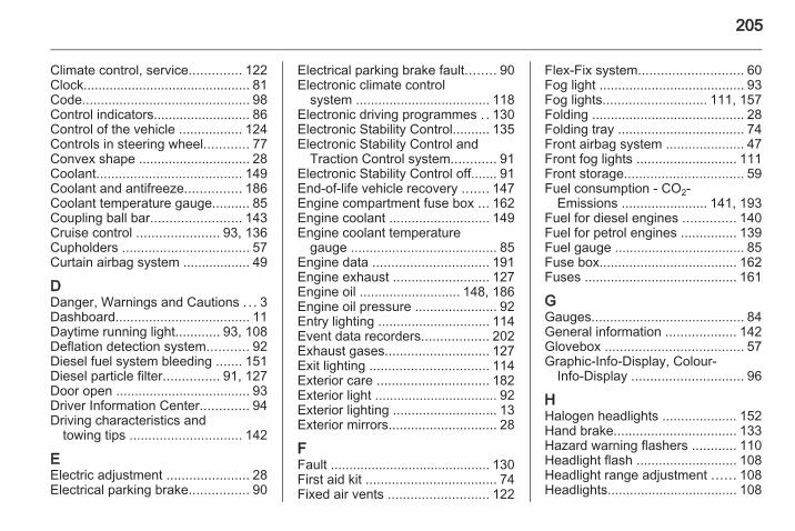
205
Climate control, service.............. 122Clock............................................. 81Code............................................. 98Control indicators.......................... 86Control of the vehicle ................. 124Controls in steering wheel............ 77Convex shape .............................. 28Coolant....................................... 149Coolant and antifreeze............... 186Coolant temperature gauge.......... 85Coupling ball bar........................ 143Cruise control ...................... 93, 136Cupholders .................................. 57Curtain airbag system .................. 49
DDanger, Warnings and Cautions . . . 3Dashboard.................................... 11Daytime running light............ 93, 108Deflation detection system........... 92Diesel fuel system bleeding ....... 151Diesel particle filter............... 91, 127Door open .................................... 93Driver Information Center............. 94Driving characteristics and
towing tips .............................. 142
EElectric adjustment ...................... 28Electrical parking brake................ 90
Electrical parking brake fault........ 90Electronic climate control
system .................................... 118Electronic driving programmes . . 130Electronic Stability Control.......... 135Electronic Stability Control and
Traction Control system............ 91Electronic Stability Control off....... 91End-of-life vehicle recovery ....... 147Engine compartment fuse box ... 162Engine coolant ........................... 149Engine coolant temperature
gauge ....................................... 85Engine data ............................... 191Engine exhaust .......................... 127Engine oil ........................... 148, 186Engine oil pressure ...................... 92Entry lighting .............................. 114Event data recorders.................. 202Exhaust gases............................ 127Exit lighting ................................ 114Exterior care .............................. 182Exterior light ................................. 92Exterior lighting ............................ 13Exterior mirrors............................. 28
FFault ........................................... 130First aid kit ................................... 74Fixed air vents ........................... 122
Flex-Fix system............................ 60Fog light ....................................... 93Fog lights............................ 111, 157Folding ......................................... 28Folding tray .................................. 74Front airbag system ..................... 47Front fog lights ........................... 111Front storage................................ 59Fuel consumption - CO2-
Emissions ....................... 141, 193Fuel for diesel engines .............. 140Fuel for petrol engines ............... 139Fuel gauge ................................... 85Fuse box..................................... 162Fuses ......................................... 161
GGauges......................................... 84General information ................... 142Glovebox ..................................... 57Graphic-Info-Display, Colour-
Info-Display .............................. 96
HHalogen headlights .................... 152Hand brake................................. 133Hazard warning flashers ............ 110Headlight flash ........................... 108Headlight range adjustment ...... 108Headlights................................... 108

206
Headlights when driving abroad 109Head restraint adjustment ............. 8Head restraints ............................ 34Heated ......................................... 29Heated rear window ..................... 32Heated steering wheel ................. 78Heating ........................................ 40Heating and ventilation system . 116High beam ........................... 93, 108High beam assist........................ 110Hill start assist ........................... 134Horn ....................................... 14, 78
IIdentification plate ..................... 190Ignition switch positions ............. 125Immobiliser ............................ 27, 92Instrument panel fuse box ......... 164Instrument panel illumination ..... 161Instrument panel illumination
control .................................... 112Instrument panel overview ........... 11Interior care ............................... 184Interior lights ...................... 113, 160Interior mirrors.............................. 29Interruption of power supply ...... 130Introduction .................................... 3ISOFIX child restraint systems .... 56
JJump starting ............................. 178
KKeys ............................................. 19
LLashing eyes ............................... 72Light covers, misted.................... 112Lighting....................................... 107Lighting features......................... 114Light switch ................................ 107Load compartment ................ 25, 69Load compartment cover ............. 70Load compartment fuse box ...... 165Loading information ..................... 75Low fuel ....................................... 92
MMalfunction indicator light ............ 89Manual anti-dazzle ...................... 29Manual mode ............................. 130Manual transmission .................. 131Manual windows .......................... 30Memorised settings...................... 21Messages..................................... 98Mirror adjustment ........................... 8Mirrors.................................... 28, 29Misted light covers ..................... 112Moonroof ..................................... 32
NNew vehicle running-in .............. 124Number plate light ..................... 159
OOctane rating.............................. 191Odometer ..................................... 84Oil............................................... 148Oil pressure.................................. 92Outside temperature .................... 81Overrun cut-off ........................... 126
PParking ................................ 18, 126Parking assist ............................ 137Parking brake ............................ 133Parking lights ............................. 112Particulate filter........................... 127Performance .............................. 192Performing work ........................ 147Personalisation........................... 102Pollen filter ................................. 122Power outlets ............................... 82Power windows ............................ 30Preheating ................................... 91
QQuickheat................................... 121

207
RRadio remote control ................... 19Reading lights ............................ 113Rear carrier system...................... 60Rear doors ................................... 25Rear floor storage cover .............. 71Rear fog light ............................... 93Rear fog lights ........................... 111Rear seats ................................... 40Rear storage................................. 70Rear window wiper/washer .......... 80Recommended fluids and
lubricants ................................ 186Reduced engine power................ 92Refuelling ................................... 140Remote control............................. 19Retained power off..................... 125Reversing lights ......................... 112Roof rack ..................................... 75
SSafety belts................................... 43Safety net .................................... 72Seat adjustment ....................... 6, 36Seat belt ........................................ 8Seat belt reminder ....................... 88Seat belts ..................................... 43Seat heating................................. 40Seat position ................................ 35
Selector lever ............................. 129Service ............................... 122, 185Service display ............................ 85Service information .................... 185Service vehicle soon .................... 89Side airbag system ...................... 48Side turn signal lights ................ 159Spare wheel ............................... 176Speedometer ............................... 84Starting off ................................... 17Starting the engine .................... 125Steering wheel adjustment ...... 9, 77Steering wheel controls ............... 77Steering wheel, heated................. 78Sunglasses storage ..................... 59Sunvisor lights ........................... 113Sun visors .................................... 32Symbols ......................................... 4
TTachometer ................................. 84Tailgate......................................... 25Tail lights ................................... 157Technical data............................ 191Three-point seat belt .................... 44Tools .......................................... 167Top-tether fastening eyes ............ 56Towing another vehicle ............. 181Towing a trailer........................... 142Towing equipment ..................... 143
Towing eye................................. 180Towing hitch installation
dimensions ............................. 201Towing the vehicle ..................... 180Traction Control system ............. 134Traction Control system off........... 91Trailer stability assist ................. 145Trailer towing ............................. 142Transmission ............................... 16Transmission display ................. 128Tread depth ............................... 169Trip computer ............................ 101Trip odometer .............................. 84Tunnel detection......................... 108Turn and lane-change signals ... 111Turn signal ................................... 88Tyre chains ................................ 170Tyre changing............................. 174Tyre deflation detection system . 169Tyre designations ...................... 168Tyre pressure ............................ 168Tyre pressures ........................... 198Tyre repair kit ............................. 171Tyres and wheel size, changing. 170
UUltrasonic parking assist .............. 91Underseat storage ....................... 59Upholstery, cleaning................... 184

208
Upshift.......................................... 90Using this manual .......................... 3
VVariable effort steering................. 91Vehicle dimensions .................... 196Vehicle Identification Number .... 189Vehicle messages ....................... 98Vehicle personalisation ............. 102Vehicle specific data ...................... 3Vehicle storage........................... 146Vehicle unlocking ........................... 6Vehicle weight ........................... 195Ventilation................................... 116
WWarning chimes ......................... 100Warning triangle .......................... 74Washer and wiper systems ......... 14Washer fluid ............................... 150Washing the vehicle................... 182Welcome lighting........................ 114Wheel changing ......................... 174Wheel covers ............................. 170Wheels and tyres ....................... 168Windows....................................... 30Windscreen wiper/washer ........... 79Winter tyres ............................... 168Wiper blade replacement .......... 151


![[CHEVROLET] Manual Inyeccion Multec Chevrolet Meriva 18](https://img.pdfslide.us/doc/110x75/577c83ae1a28abe054b5c908/chevrolet-manual-inyeccion-multec-chevrolet-meriva-18.jpg)