Embed Size (px)
Citation preview
MERIT: MEsh of RF sensorsfor Indoor TrackingYui-Wah Lee
Bell Laboratories101 Crawfords CornerRoadHolmdel, NJ 07724, USA
Email: [email protected]
Erich StuntebeckGeorgia Instituteof Technology
Schoolof ElectricalandComputer EngineeringAtlanta, Georgia, USA
Email: [email protected]
ScottC. MillerBell Laboratories
101 Crawfords CornerRoadHolmdel, NJ 07724, USAEmail: [email protected]
Abstract— One of the traditional approachesto indoor track-ing utili zes non-RF ranging techniques, such as infrar ed orultrasound. The problem with thesenon-RF ranging techniquesis that they do not work well when the tracking devices areburied in users’ wallets or bags. As a result, there has beenconsiderable interest in using only RF techniques for indoortracking. Existing RF-only techniques,however, typically requirea costly site survey and a floor-plan. In this paper, we presenttheMERIT system that we designed,implemented, and evaluated.MERIT is significantly differ ent fr om existing systemsin thatit is pure RF-based yet it does not require a site survey nora floor-plan. MERIT tracks users to a room granularity , andit can disambiguate neighboring rooms. This disambiguationis challenging becauseRF signals can traverse thr ough walls.Also, becauseof indoor multipath interfer ence, it is difficult tocorrelatesignal strength with distance.In this work, we proposedtwo techniquesfor accurate disambiguation: spatial diversity andRF reflector. In our evaluation MERIT achieved an accuracyof 98.9%. MERIT was first conceived for a telecommunicationapplication – intelli gent telephonecall routing, but it can also beused for other location-aware services.
I . INTRODUCTION
An active researcharea in mobile computing concernslocation-dependentor location-aware services.A fundamentalpremise of these services is that a better service can beprovided by knowing the locationof a mobileentity (userorequipment).
For example, if our phone systemknows the whereaboutsof a phone user, her friends no longer needto guess whichphone number (home, office, cellphone) they should call toreachthe user. They canalwaysdial the same“user” numberandrely on the phone systemto redirect the call intelligentlyto the physical phone that is mostappropriate.
In the above scenario, the subsystemthat determines thelocationof themobile entitiescanbecalleda location-trackingsystemor location-support system.The techniquesfor indoorlocation tracking canbe classifiedinto two broad categories:thoserely on non-RF (radio frequency) ranging techniques,andthoserely purelyon RF techniques.In thefirst categories,infrared or ultrasound may be usedalone[1] or togetherwithRF [2] for indoor location determination. The problem withinfraredandultrasound, however, is thatthey do not work wellwhen the device is buried in users’wallets or bags,becausetheir signalscaneasilybe blocked in thesesituations.
It is for this reasonthat there has been a considerableinterest in using pure RF techniques, because radio waves
canbetterpenetratethrough obstacles.While therehave beensomesolutionsin this space,they usuallyinvolve a high setupcost.Thesesystemstypically require a careful site survey andfloor-plan to establishan empirical model of the indoor radioenvironment [3], [4], [5].
Someworks claimed that they could skip the site surveyby relying on a theoreticalmodel of signal strengthattenua-tion over distance[3], [6], [7]. However, as reported in theliterature[8], and also confirmed in our own experiment inSectionIV-B, in anindoor environment,thereis aphenomenoncalledmultipathinterference. That is, RF signalsemittedfroma transmittercan take different paths(directly and indirectlythrough reflections from other indoor surfaces)to reachthereceiver. Depending on the exact path lengths, therewill becertain phase differences among the waves coming throughthesedifferent paths.The signalsmay constructively or de-structively interferewith eachother at the receiver, resultingin a higher or lower received signalstrength. As a result,it isdifficult to find anaccuratetheoreticalmodel thatmapssignalstrengthto indoor distance.
Usinganempiricalor theoreticalmodel,thesesystemsthenemploy triangulation [6], [7] or pattern matching [3], [4] toestablishthecoordinatesof themobileentity basedon signal-strengthmeasurements. In many applications, however, thelocation information at a room granularity is more importantthan the exact coordinates.Therefore, thesesystemswouldobtain the coordinatesfirst, and thenusea floor-plan to lookup the room identity. This approach is sub-optimal and itunnecessarilyrequires a floor-plan, which is not always easyto obtainespeciallyfor individual users.
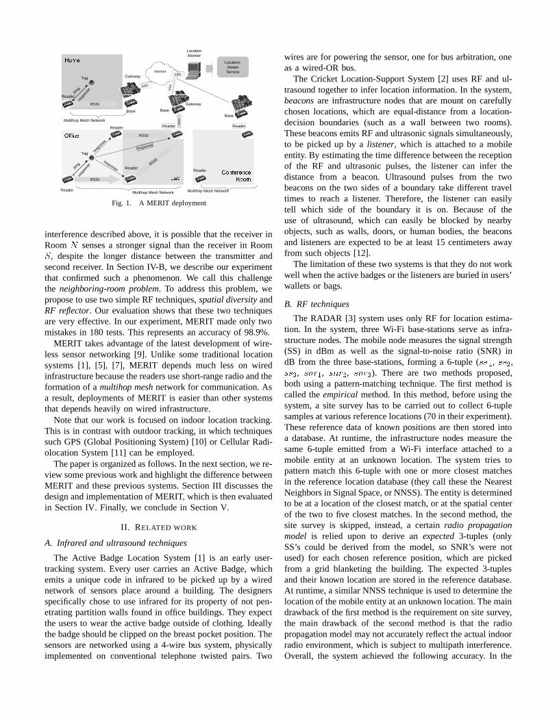
In contrastto thesepreviousworks,we have built an indoortracking systemthat is pureRF-based,yet it doesnot requirea costly site survey nor a floor-plan. Our system can beincrementally deployed by individual users (as opposed toa facility manager). We call our systemMERIT, for MEshof RF sensorsfor Indoor Tracking (Figure 1). Our originalapplication is an intelligent call routing service,but MERITcanalsobe usedfor other location-awareservices.
In somesense,MERIT is proximity-based.The main chal-lengeof a proximity-basedtechnique, however, is whetheritcan disambiguate two neighboring rooms. Suppose we havea transmitterand two receivers, andwe placethe transmitterand the first receiver in the sameroom
�, and then place
the secondreceiver in the next room � . Due to multipath
Reader
Reader
Location-AwareService
Base
LocationMonitor
response
response
RSSI
RSSI
ping
resp
onse
Tag
RSSI
Base
��� � � ���
� �
��� ���Internet
RSSI
RS
SI
RS
SI
RSSIGateway
Gateway
Reader
Reader
��� ��� ��� � ������ � ���
Base
Multihop Mesh Network
Reader
Multihop Mesh Network
Multihop Mesh Network
Reader
ping
resp
onse
resp
onse
Tag
ReaderRSSI
Fig. 1. A MERIT deployment
interferencedescribedabove, it is possiblethat the receiver inRoom � sensesa stronger signal than the receiver in Room
, despitethe longer distancebetweenthe transmitterandsecondreceiver. In SectionIV-B, we describe our experimentthat confirmed such a phenomenon. We call this challengethe neighboring-room problem. To addressthis problem, weproposeto usetwo simpleRF techniques,spatialdiversity andRF reflector. Our evaluation shows that thesetwo techniquesarevery effective. In our experiment,MERIT madeonly twomistakes in 180 tests.This represents an accuracy of 98.9%.
MERIT takesadvantageof the latestdevelopment of wire-less sensornetworking [9]. Unlike sometraditional locationsystems[1], [5], [7], MERIT depends much less on wiredinfrastructurebecausethereadersuseshort-rangeradioandtheformationof a multihop meshnetwork for communication.Asa result,deploymentsof MERIT is easierthanothersystemsthat dependsheavily on wired infrastructure.
Note that our work is focusedon indoor locationtracking.This is in contrastwith outdoor tracking, in which techniquessuchGPS(Global PositioningSystem)[10] or Cellular Radi-olocation System[11] canbe employed.
Thepaperis organizedasfollows. In thenext section,were-view someprevious work andhighlight thedifferencebetweenMERIT andtheseprevious systems.SectionIII discussesthedesignandimplementationof MERIT, which is thenevaluatedin SectionIV. Finally, we conclude in SectionV.
I I . RELATED WORK
A. Infrared and ultrasound techniques
The Active BadgeLocation System[1] is an early user-tracking system.Every user carriesan Active Badge,whichemits a unique code in infrared to be picked up by a wirednetwork of sensorsplace around a building. The designersspecificallychoseto useinfrared for its property of not pen-etratingpartition walls found in office buildings. They expectthe usersto wearthe active badge outsideof clothing. Ideallythebadgeshouldbeclipped on thebreastpocket position.Thesensorsare networked using a 4-wire bus system,physicallyimplemented on conventional telephone twisted pairs. Two
wiresarefor powering thesensor, onefor busarbitration, oneasa wired-ORbus.
The Cricket Location-Support System[2] usesRF and ul-trasound together to infer locationinformation. In the system,beacons are infrastructurenodes that are mount on carefullychosenlocations,which are equal-distancefrom a location-decision boundaries (such as a wall betweentwo rooms).Thesebeacons emitsRF andultrasonicsignalssimultaneously,to be picked up by a listener, which is attachedto a mobileentity. By estimatingthetime differencebetweenthereceptionof the RF and ultrasonic pulses,the listener can infer thedistance from a beacon. Ultrasound pulses from the twobeacons on the two sidesof a boundary take different traveltimes to reach a listener. Therefore, the listener can easilytell which side of the boundary it is on. Becauseof theuse of ultrasound, which can easily be blocked by nearbyobjects,suchas walls, doors,or humanbodies, the beaconsand listenersareexpectedto be at least15 centimetersawayfrom suchobjects[12].
Thelimitation of thesetwo systemsis thatthey do not workwell whentheactivebadges or thelistenersareburied in users’walletsor bags.
B. RF techniques
The RADAR [3] systemusesonly RF for locationestima-tion. In the system,threeWi-Fi base-stations serve as infra-structure nodes. Themobilenodemeasuresthesignalstrength(SS) in dBm as well as the signal-to-noise ratio (SNR) indB from the threebase-stations,forming a 6-tuple ( !"!$# , !%!'& ,!%!'( , !*),+-# , !.),+%& , !.)/+%( ). There are two methods proposed,both using a pattern-matching technique. The first method iscalledthe empirical method. In this method, before usingthesystem,a site survey hasto be carriedout to collect 6-tuplesamplesat variousreferencelocations(70 in theirexperiment).Thesereferencedataof known positionsare thenstoredintoa database.At runtime, the infrastructure nodes measure thesame6-tuple emitted from a Wi-Fi interface attachedto amobile entity at an unknown location. The systemtries topatternmatchthis 6-tuple with one or more closestmatchesin the reference locationdatabase(they call thesethe NearestNeighborsin SignalSpace,or NNSS).Theentity is determinedto beat a locationof theclosestmatch,or at thespatialcenterof the two to five closestmatches.In the secondmethod,thesite survey is skipped,instead,a certain radio propagationmodel is relied upon to derive an expected3-tuples (onlySS’s could be derived from the model, so SNR’s were notused) for eachchosenreferenceposition, which are pickedfrom a grid blanketing the building. The expected3-tuplesandtheir known locationarestoredin the referencedatabase.At runtime,a similar NNSStechniqueis usedto determine thelocationof themobile entityat anunknown location.Themaindrawbackof thefirst method is therequirementon sitesurvey,the main drawback of the secondmethod is that the radiopropagation model maynot accuratelyreflecttheactualindoorradio environment, which is subjectto multipathinterference.Overall, the systemachieved the following accuracy. In the
empirical method, 25%of thetestshadanerrorthatwaslargerthan 4.69
0meters,somein the rangeof 10s of meters,50%
haderrors largerthan2.94meters.In thesecondmethod, 50%of the testshadan error that was larger than4.3 meters.
TheLANDMARC system[13] usesactiveRFID technologyfor ranging. It requiresa large number of referencetags tobe placedin the environment.Thesetagshave to be placedevery oneor two meters.In a sense,thesereferencetagsservemoreor lessthesamerole of a sitesurvey, sincethey establishreferencesignalstrengthsatknown locations.Theadvantageisthatthereferenceparameters aredetermineddynamically, soitcanaccount for temporal fluctuationof radioenvironment(e.g.dueto presenceor absenceof people, equipment,or furniture).However, theplacement of thesereference tagsmay imposeapracticalchallenge.This is becausethemobileentitiesusuallycarrytheactive tagsatchestor waistlevel (i.e.unlikely to beatan above-headposition). Therefore, thesereferencetagsneedto be placedat a similar level, yet they have to be denselydeployed (every one or two meters).It is not clear how thiscanbe done in a typical office or homeenvironment.
Somesystems[7], [6] rely on a theoretical signal-strengthattenuation model. As discussedpreviously, thesemodelsmaynot matchthe reality in an indoor radio environment due tomultipathinterference.
Cisco has a Wireless Location Appliance [4] that usereceived signalstrengthandfingerprinting technology to track802.11 device in a 802.11 WLAN network. The systemhasan accuracy of a few meters.The systemappearsto require asite survey anda floor-plan.
Ubisenseis a commercial product that usesUWB as theranging technology [5]. It is different from the previoussystemsbecause it doesnot rely on signalstrengthbut ratherTime Difference of Arrival (TDOA) and Angle of Arrival(AOA) of radio wave. In the system,eachcell is composedof four to seven sensors that are installed in fixed knownpositionsin anarea.Thesesensorsarenetworkedby Ethernet,but they alsohasa conventional RF transceiver aswell asanphasearrayof UWB receivers. Themobile entity would carrya tag which has a conventional RF transceiver and a UWBtransmitter. Oneof thesensorin a cell will serve asthemasterandcoordinatesa TDMA network usingthe conventional RFchannel. The sensorsusea combination of TDOA and AOAtechniques to determine the location of a transmitting tag.The systemhas a location accuracy of about 15cm across95% readings. Their systemprobably requires a very preciseclock becausethe travel time of RF acrossa distanceof 15cmis only 0.5 ns. This increasesthe cost of manufacturing thesensors,making Ubisensemore suitable for deployment byfacility managers thanby individual users.
If the room information is required, all these systemsdetermine the coordinatesof the mobile entity first, and thenlook up the room identity from a floor-plan. Someof themrequire a costly site survey, somerequirea densedeploymentof referencetags,somerely on a theoretical indoor attenuationmodel of signalstrengthover distance,which may not matchreality. In contrast, MERIT determines the room identity
Registrar(C)
LocationM
onitor(Java)
SerialForwarder(C
)
MoteSensor(nesC)
Tag(nesC)
TinyOS(Multihop,
ActiveMessage,B-MAC)
TinyOS(Multihop,
ActiveMessage,B-MAC)
Linux(TCP/IP,PPP)
JVM(TCP/IP)
Linux(TCP/IP)
RegU
pdate(C)
BackhaulM
gr(bash )
Tag Reader Gateway Loc. Mon. Registrar
MICA2/MICA2DOT MICA2 Stargate PC PC
RegQ
uery(Java)
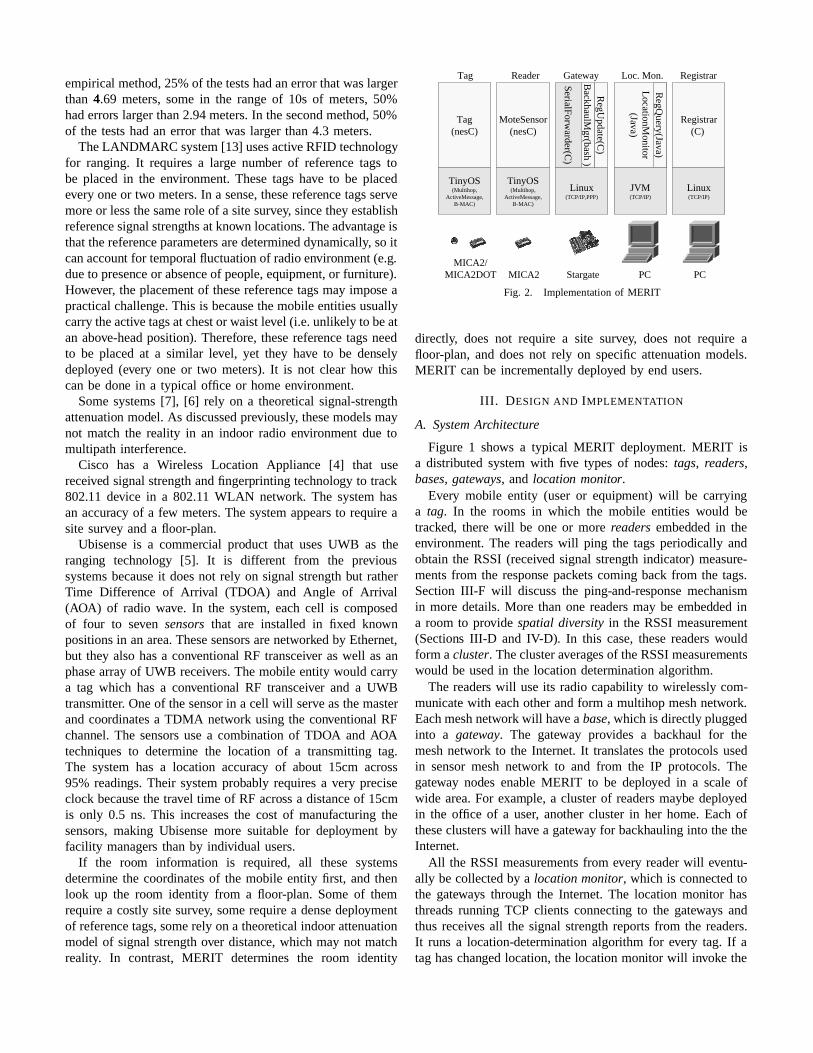
Fig. 2. Implementation of MERIT
directly, does not require a site survey, does not require afloor-plan, and doesnot rely on specificattenuationmodels.MERIT canbe incrementally deployed by endusers.
I I I . DESIGN AND IMPLEMENTATION
A. SystemArchitecture
Figure 1 shows a typical MERIT deployment. MERIT isa distributed systemwith five typesof nodes: tags, readers,bases, gateways, and location monitor.
Every mobile entity (user or equipment) will be carryinga tag. In the rooms in which the mobile entities would betracked, therewill be one or more readers embedded in theenvironment. The readerswill ping the tagsperiodically andobtain the RSSI (received signal strength indicator) measure-mentsfrom the responsepacketscomingback from the tags.SectionIII-F will discussthe ping-and-responsemechanismin moredetails.More thanone readersmay be embedded ina room to provide spatial diversity in the RSSI measurement(Sections III-D and IV-D). In this case,thesereaderswouldform a cluster. Theclusteraveragesof theRSSImeasurementswould be usedin the locationdetermination algorithm.
The readers will useits radio capability to wirelesslycom-municatewith eachotherandform a multihopmeshnetwork.Eachmeshnetwork will havea base, which is directlypluggedinto a gateway. The gateway provides a backhaul for themeshnetwork to the Internet. It translatesthe protocols usedin sensormeshnetwork to and from the IP protocols. Thegateway nodes enableMERIT to be deployed in a scaleofwide area.For example, a clusterof readersmaybe deployedin the office of a user, another cluster in her home. Eachoftheseclusterswill have a gateway for backhauling into thetheInternet.
All the RSSImeasurementsfrom every readerwill eventu-ally becollectedby a locationmonitor, which is connected tothe gateways through the Internet. The location monitor hasthreads running TCP clients connecting to the gateways andthus receivesall the signal strengthreportsfrom the readers.It runs a location-determination algorithm for every tag. If ataghaschangedlocation,the locationmonitor will invoke the
API providedby anexternal system,suchasa telephone call-routing system,to inform the latter about the locationchange.
The location monitor may needthe help of a gateway ad-dressregistrarto locatethegatewaysif the latterusedynamicIP address.In Figure1 we do not show the gateway addressregistrar. We defer the discussionaboutit to SectionIII- C.
B. Implementation
Figure2 shows the hardware platforms, operating systems,andprogramminglanguagesusedfor implementingthevarioussubsystems.Figure3 shows a typical setof networking stacksrunning on thereaders,bases,gateways,andlocationmonitor,assuming3G1xRTT is usedto provide the backhaul for thegateways.
For hardware,we usetheCrossbow MICA2 (andsometimesMICA2DOT) motes[14] for the tagsand the readers.EveryMICA2 or MICA2DOT mote hasa ATmega128L 8-bit pro-cessor, a ChipconCC1000(proprietary) radio transceiver, aswell as an on-board 51-pin socket for plugging in a sensorboard, these embody the three ingredient technologies forwirelesssensornetworking: local processingpower, wirelesscommunication,andsensing.In our current version,we do notreally useany extra sensingcapability , becausethe detectionand tracking of mobile tags are done via measurement ofradiosignalstrengths.Our futureversionmay incorporatethesensingcapabilityof motion detection.
We use the Crossbow Stargate single-board computer forthe gateways [14]. The Stargate computer has a 400-MHzPXA255 XScale processor, a 51-pin socket for interfacingwith the MICA2 mote, an Ethernet interface, a CompactFlash as well as a PCMCIA slot. The gateway connectsthe sensormesh network to the Internet as follows. First,on the Stargate is plugged a MICA2 mote that serves asthe baseand communicate with the sensormesh network.Second, the backhaul interfacewith the Internet canbe doneby using the Ethernetinterface of the Stargate, or by usingother network interfaces plugged into the Compact Flashor PCMCIA slot. In our prototype we often use the SierraAirCard 555 CDMA 3G 1xRTT PCMCIA cardfor wide-areawirelessnetworking. In eithercases(Ethernet or 3G 1xRTT),the backhaul is a IP (Internet Protocol) connection. Finally,there is a program called SerialForwarder running onthe gateway. SerialForwarder takespackets received from theserial port (part of the 51-pin socket) and forward themoverto a TCP/IPserver port on the backhaul link. It alsoforwardspacketscoming from theTCP/IPserver port to theserialport.
The locationmonitor andgateway addressregistrar run onregular PCsor laptopswith IP connection.
For software, on the mote side we wrote two subsystemsin the nesClanguage for the TinyOS operating system.TheTag subsystemrunson themobiletag,andtheMeshSensorprogram runson the readersand the base.We reuseexistingTinyOS components.For example, the meshnetwork multi-hop routing capability is provided by the ReliableRoutecomponent.TinyOS also provides other essentialingredientsincluding the B-MAC protocol for the MAC (media access
CC1000
B-MAC
AM
MH
MeshSensor
CC1000
B-MAC
AM
MH
MeshSensor SerialForwarder
3G1xRTT
PPP
IP
TCP
LocMon
UART UART
3G1xRTT
PPP
IP
TCP
Reader Base Gateway LocMon
Fig. 3. Networking stacks
1. Gateway Address Update / Response
2. Gateway Address Query / Response
3. TCP Connection from SystemMonitor to Gateway
Stargate3G G/Wrunning sf.cexposes sensordata on TCP port 9001
LocationMonitorTCP clientMOTECOM=snew-sf@<registrar.domain>:9000+28
Internet
tcp/9001
StargateSierraAircard 555
Registrar
Update: GW 28Is at 166.156.x.y:9001
1a
2b
3 tcp/9000
tcp/9000
1b
PCMCIA
Response: GW 28Is at 166.156.x.y:9001
2aQuery: GW 28
3G Backhaul with dynamic address assigned by 3G carrier
Gwid=28
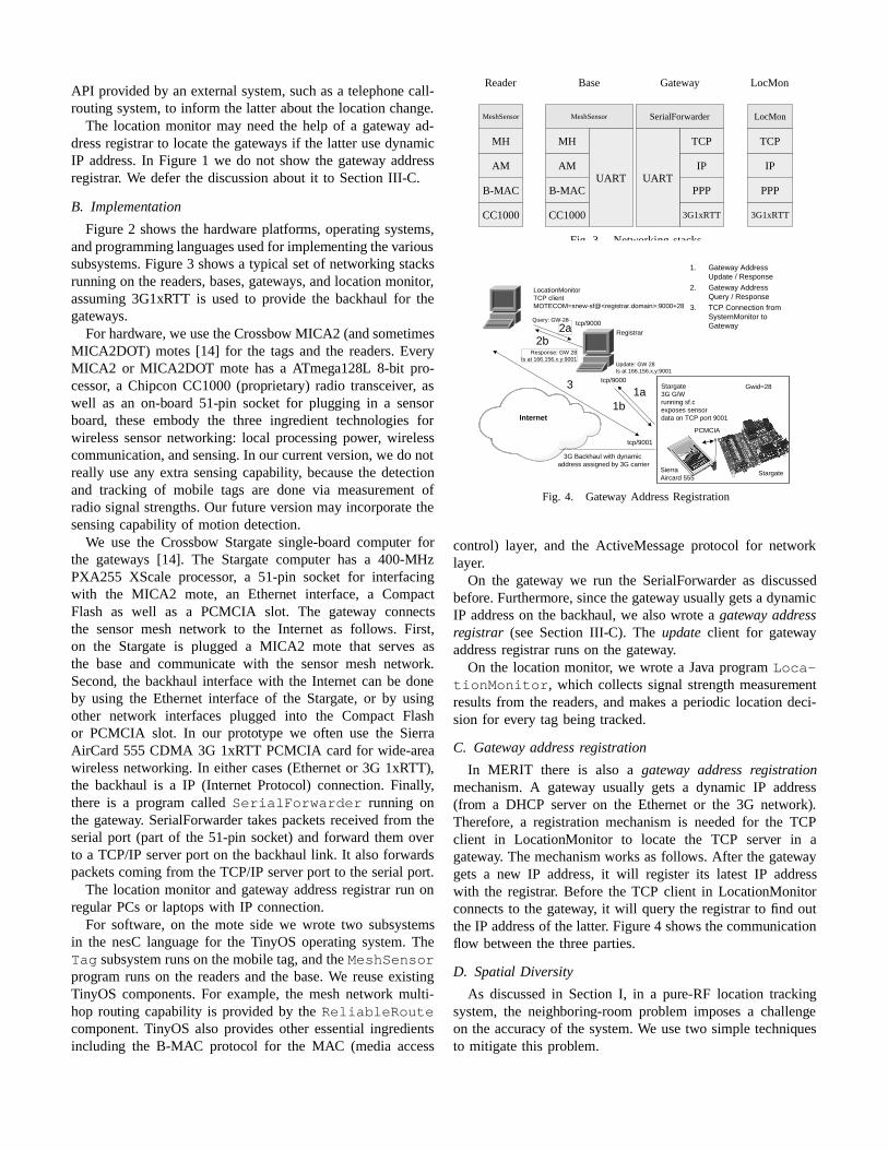
Fig. 4. Gateway AddressRegistration
control) layer, and the ActiveMessageprotocol for networklayer.
On the gateway we run the SerialForwarder as discussedbefore.Furthermore,sincethegateway usuallygetsa dynamicIP addresson the backhaul, we alsowrote a gateway addressregistrar (seeSectionIII- C). The update client for gatewayaddressregistrarrunson the gateway.
On the locationmonitor, we wrote a Java programLoca-tionMonitor, which collectssignal strengthmeasurementresultsfrom the readers,andmakes a periodic locationdeci-sion for every tag beingtracked.
C. Gateway addressregistration
In MERIT there is also a gateway address registrationmechanism. A gateway usually gets a dynamic IP address(from a DHCP server on the Ethernet or the 3G network).Therefore, a registration mechanism is needed for the TCPclient in LocationMonitor to locate the TCP server in agateway. Themechanismworksasfollows. After the gatewaygets a new IP address,it will register its latest IP addresswith the registrar. Before the TCP client in LocationMonitorconnectsto the gateway, it will querythe registrarto find outtheIP addressof thelatter. Figure4 shows thecommunicationflow betweenthe threeparties.
D. Spatial Diversity
As discussedin SectionI, in a pure-RF location trackingsystem,the neighboring-room problem imposesa challengeon the accuracy of the system.We usetwo simpletechniquesto mitigate this problem.
MICA2
Mote
.
6”
6”
7”
whipantennapointingupwards
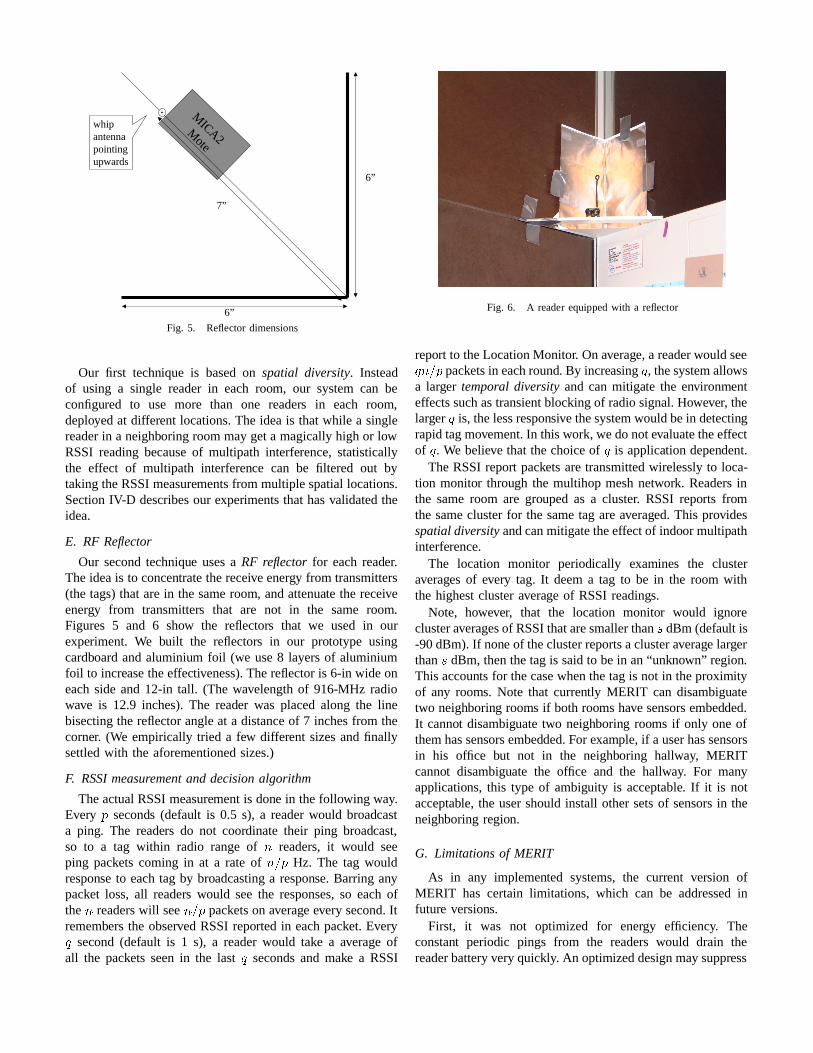
Fig. 5. Reflector dimensions
Our first technique is basedon spatial diversity. Insteadof using a single readerin each room, our systemcan beconfigured to use more than one readers in each room,deployedat different locations.The ideais thatwhile a singlereaderin a neighboring roommaygeta magicallyhigh or lowRSSI readingbecauseof multipath interference,statisticallythe effect of multipath interference can be filtered out bytakingtheRSSImeasurementsfrom multiple spatiallocations.SectionIV-D describesour experimentsthat hasvalidatedtheidea.
E. RF Reflector
Our secondtechnique usesa RF reflector for eachreader.Theideais to concentratethereceive energy from transmitters(the tags)that arein thesameroom, andattenuate the receiveenergy from transmitters that are not in the same room.Figures 5 and 6 show the reflectors that we used in ourexperiment. We built the reflectors in our prototype usingcardboardandaluminium foil (we use8 layersof aluminiumfoil to increasetheeffectiveness).Thereflectoris 6-in wide oneachside and 12-in tall. (The wavelengthof 916-MHz radiowave is 12.9 inches).The reader was placedalong the linebisectingthe reflectorangleat a distanceof 7 inchesfrom thecorner. (We empirically tried a few different sizesandfinallysettledwith the aforementionedsizes.)
F. RSSImeasurementand decisionalgorithm
TheactualRSSImeasurementis done in thefollowing way.Every 1 seconds (default is 0.5 s), a readerwould broadcasta ping. The readers do not coordinate their ping broadcast,so to a tag within radio range of 2 readers,it would seeping packets coming in at a rate of 243'1 Hz. The tag wouldresponse to eachtag by broadcastinga response.Barring anypacket loss, all readers would seethe responses,so eachofthe 2 readerswill see25361 packetson average every second.Itremembersthe observed RSSIreported in eachpacket. Every7 second(default is 1 s), a readerwould take a averageofall the packets seenin the last 7 secondsand make a RSSI
Fig. 6. A reader equippedwith a reflector
report to theLocationMonitor. Onaverage,a readerwouldsee7 24361 packetsin eachround. By increasing7 , thesystemallowsa larger temporal diversity and can mitigate the environmenteffectssuchastransientblockingof radiosignal.However, thelarger 7 is, thelessresponsive thesystemwouldbein detectingrapidtagmovement.In thiswork, wedonotevaluatetheeffectof 7 . We believe that thechoiceof 7 is application dependent.
The RSSIreport packetsaretransmittedwirelesslyto loca-tion monitor through the multihop meshnetwork. Readersinthe sameroom are grouped as a cluster. RSSI reports fromthe sameclusterfor the sametag areaveraged.This providesspatialdiversityandcanmitigatetheeffectof indoor multipathinterference.
The location monitor periodically examines the clusteraverages of every tag. It deema tag to be in the room withthe highestclusteraverage of RSSI readings.
Note, however, that the location monitor would ignoreclusteraveragesof RSSIthataresmallerthan 8 dBm(default is-90dBm). If none of theclusterreportsaclusteraverage largerthan 8 dBm, thenthetagis saidto bein an“unknown” region.This accounts for thecasewhenthetagis not in theproximityof any rooms. Note that currently MERIT can disambiguatetwo neighboring rooms if bothroomshave sensorsembedded.It cannot disambiguatetwo neighboring rooms if only oneofthemhassensorsembedded.For example, if a userhassensorsin his office but not in the neighboring hallway, MERITcannot disambiguate the office and the hallway. For manyapplications, this type of ambiguity is acceptable. If it is notacceptable, the usershouldinstall othersetsof sensorsin theneighboring region.
G. Limitationsof MERIT
As in any implemented systems,the current version ofMERIT has certain limitations, which can be addressedinfuture versions.
First, it was not optimized for energy efficiency. Theconstant periodic pings from the readerswould drain thereaderbatteryveryquickly. An optimizeddesignmaysuppress
unnecessarilyping basedone someother sensorinput, suchas infrare9 d motion detection,or microphone sounddetection.
Second, the current MERIT doesnot addressprivacy con-cern. A future version of MERIT that is privacy-friendlymay collect RSSI measurements on the tag insteadof on theinfrastructure nodes.Insteadof using a centralizedlocationmonitor for all users,each user may configure their ownpersonal locationmonitor.
Third, the current MERIT assumesthat the neighboringrooms are of similar sizes. This assumptionmay not holdin reality. This problem can be mitigated by using multipleclustersin the bigger rooms. In the future, we may designsomemethods to adjusttheclusteraveragesto accountfor thesizedifferences.
IV. EVALUATION
All experimentsdescribedbelow, except thosediscussedinSectionIV-A, werecarriedout in an indoor environment.
A. RSSIvs Distance
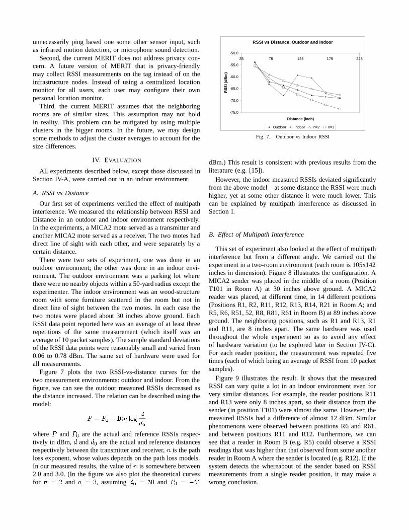
Our first setof experimentsverified the effect of multipathinterference.We measuredthe relationship betweenRSSIandDistancein an outdoor and indoor environment respectively.In theexperiments,a MICA2 moteservedasa transmitterandanother MICA2 moteservedasa receiver. Thetwo moteshaddirect line of sight with eachother, andwereseparatelyby acertaindistance.
There were two sets of experiment, one was done in anoutdoor environment; the other was done in an indoor envi-ronment. The outdoor environmentwas a parking lot wheretherewerenonearbyobjectswithin a50-yardradiusexcept theexperimenter. The indoor environment wasan wood-structureroom with some furniture scatteredin the room but not indirect line of sight betweenthe two motes.In eachcasethetwo moteswere placedabout 30 inchesabove ground. EachRSSIdatapoint reportedherewasanaverageof at leastthreerepetitions of the same measurement (which itself was anaverage of 10packetsamples).Thesamplestandard deviationsof theRSSIdatapointswerereasonably smallandvariedfrom0.06 to 0.78 dBm. The sameset of hardware were usedforall measurements.
Figure 7 plots the two RSSI-vs-distance curves for thetwo measurementenvironments:outdoor andindoor. Fromthefigure, we canseethe outdoor measuredRSSIsdecreasedasthedistanceincreased. Therelationcanbedescribedusingthemodel:
:<;=:?>A@CB6D 2FE�GIHJJ >
where:
and: >
are the actualand referenceRSSIsrespec-tively in dBm,
Jand
J >aretheactualandreference distances
respectively betweenthetransmitterandreceiver, 2 is thepathlossexponent,whosevaluesdepends on thepathlossmodels.In our measuredresults,thevalueof 2 is somewherebetween2.0 and3.0. (In the figure we alsoplot the theoretical curvesfor 2 ;LK
and 2 ;LM, assuming
J >C;LNIDand
:,>O;P@QN�R
RSSI vs Distance; Outdoor and Indoor
-75.0
-70.0
-65.0
-60.0
-55.0
-50.0
25 75 125 175 225
Distance (inch)
RS
SI (
dB
m)
Outdoor Indoor n=2 n=3
Fig. 7. Outdoorvs Indoor RSSI
dBm.) This result is consistentwith previous resultsfrom theliterature(e.g. [15]).
However, the indoor measuredRSSIsdeviatedsignificantlyfrom theabove model – at somedistancetheRSSIweremuchhigher, yet at someother distanceit were much lower. Thiscan be explained by multipath interference as discussedinSectionI.
B. Effect of Multipath Interference
This setof experimentalsolookedat theeffect of multipathinterferencebut from a different angle. We carried out theexperimentin a two-room environment(eachroomis 105x142inchesin dimension). Figure8 illustratesthe configuration. AMICA2 senderwasplacedin the middle of a room (PositionT101 in Room A) at 30 inches above ground. A MICA2readerwas placed, at different time, in 14 differentpositions(PositionsR1, R2, R11,R12,R13,R14,R21 in RoomA; andR5,R6,R51,52,R8,R81,R61in RoomB) at 89 inchesaboveground. The neighboring positions,suchas R1 and R13, R1and R11, are 8 inchesapart.The samehardware was usedthroughout the whole experiment so as to avoid any effectof hardware variation (to be explored later in SectionIV-C).For eachreaderposition, the measurement was repeatedfivetimes(eachof which beinganaverage of RSSIfrom 10 packetsamples).
Figure 9 illustratesthe result. It shows that the measuredRSSI canvary quite a lot in an indoor environment even forvery similar distances.For example, the readerpositionsR11andR13 wereonly 8 inches apart,so their distancefrom thesender(in positionT101)werealmostthesame.However, themeasured RSSIshada difference of almost12 dBm. Similarphenomenons were observed betweenpositionsR6 andR61,and betweenpositions R11 and R12. Furthermore, we canseethat a readerin RoomB (e.g. R5) could observe a RSSIreadingsthatwashigher thanthatobservedfrom someanotherreaderin RoomA wherethesenderis located(e.g.R12).If thesystemdetectsthe whereabout of the senderbasedon RSSImeasurementsfrom a single reader position, it may make awrong conclusion.
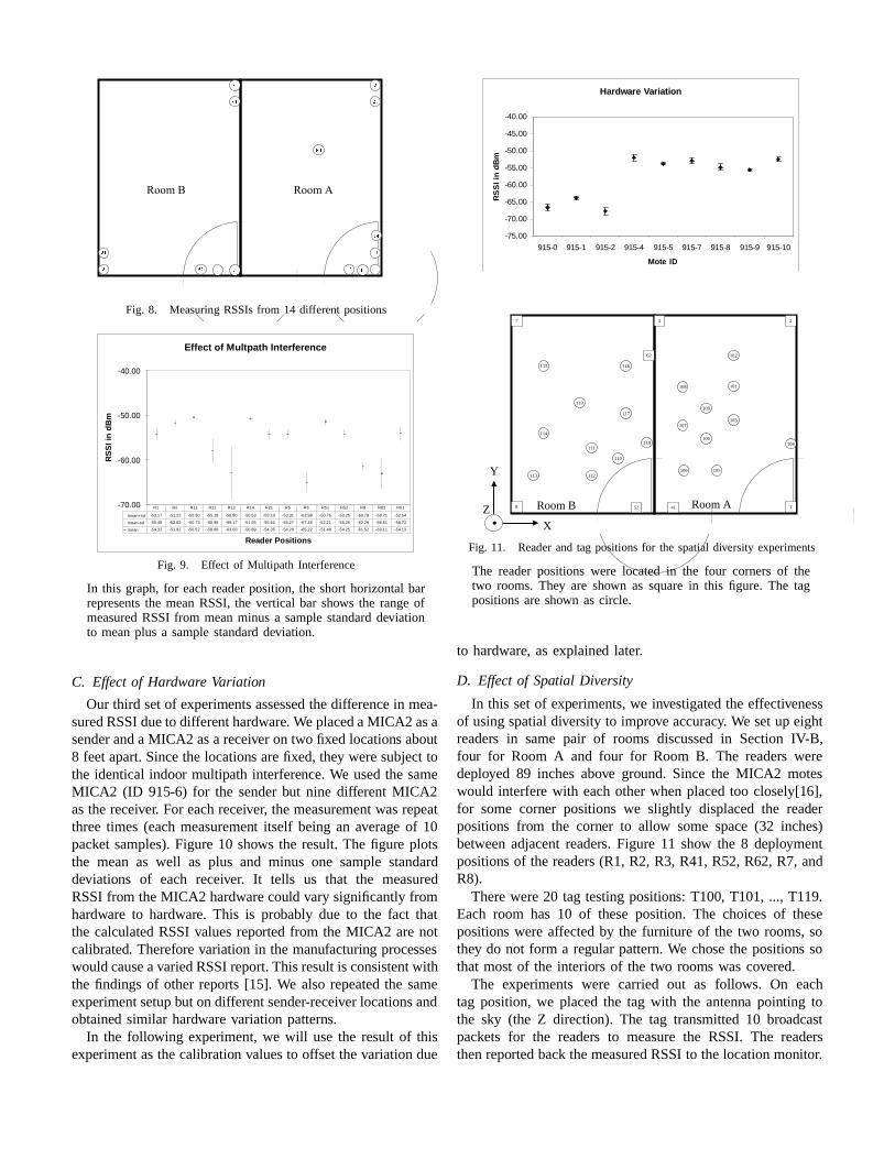
Fig. 8. Measuring RSSIsfrom 14 differentpositions
Effect of Multpath Interference
-70.00
-60.00
-50.00
-40.00
Reader Positions
RS
SI i
n d
Bm
mean+sd -53.17 -51.22 -50.30 -55.18 -56.90 -50.53 -53.10 -53.31 -62.98 -50.76 -53.25 -60.78 -59.71 -52.54
mean-sd -55.46 -52.62 -50.73 -60.98 -69.17 -51.25 -55.60 -55.27 -67.45 -52.21 -55.26 -62.26 -66.51 -55.72
mean -54.32 -51.92 -50.52 -58.08 -63.03 -50.89 -54.35 -54.29 -65.22 -51.48 -54.25 -61.52 -63.11 -54.13
R1 R2 R11 R12 R13 R14 R21 R5 R6 R51 R52 R8 R81 R61
Fig. 9. Effect of Multi path Interference
In this graph,for eachreaderposition,the shorthorizontalbarrepresentsthe meanRSSI, the vertical bar shows the rangeofmeasuredRSSI from meanminusa samplestandarddeviationto meanplus a samplestandarddeviation.
C. Effect of Hardware Variation
Our third setof experimentsassessedthedifferencein mea-suredRSSIdueto different hardware. WeplacedaMICA2 asasenderanda MICA2 asa receiver on two fixedlocations about8 feetapart.Sincethe locations arefixed,they weresubjecttothe identical indoor multipath interference.We usedthe sameMICA2 (ID 915-6) for the senderbut nine differentMICA2asthereceiver. For eachreceiver, themeasurementwasrepeatthreetimes (eachmeasurement itself being an average of 10packet samples).Figure10 shows the result.The figure plotsthe mean as well as plus and minus one samplestandarddeviations of each receiver. It tells us that the measuredRSSIfrom theMICA2 hardwarecould vary significantlyfromhardware to hardware. This is probably due to the fact thatthe calculatedRSSIvaluesreported from the MICA2 arenotcalibrated. Thereforevariationin the manufacturing processeswouldcauseavariedRSSIreport.This resultis consistentwiththe findingsof otherreports [15]. We also repeatedthe sameexperimentsetupbut ondifferentsender-receiver locationsandobtained similar hardwarevariation patterns.
In the following experiment, we will usethe result of thisexperimentasthecalibration valuesto offset thevariationdue
Hardware Variation
-75.00
-70.00
-65.00
-60.00
-55.00
-50.00
-45.00
-40.00
915-0 915-1 915-2 915-4 915-5 915-7 915-8 915-9 915-10
Mote ID
RS
SI
in d
Bm
Fig. 10. Measured RSSIsby different hardware
2
1
62
7
8 52
3
41
101
Room ARoom B
102
103
104
105106
107
108
109
100
110
111
112113
114
115 116
117
118
119
. X
Y
Z
Fig. 11. Reader and tag positions for the spatial diversity experiments
The readerpositionswere located in the four cornersof thetwo rooms.They are shown as squarein this figure. The tagpositionsareshown ascircle.
to hardware, asexplained later.
D. Effect of Spatial Diversity
In this setof experiments,we investigatedthe effectivenessof usingspatialdiversity to improve accuracy. We setup eightreaders in same pair of rooms discussedin Section IV-B,four for Room A and four for Room B. The readers weredeployed 89 inchesabove ground. Since the MICA2 moteswould interfere with eachotherwhenplacedtoo closely[16],for some corner positions we slightly displacedthe readerpositions from the corner to allow somespace(32 inches)betweenadjacentreaders. Figure 11 show the 8 deploymentpositions of the readers(R1, R2, R3, R41,R52,R62,R7, andR8).
Therewere20 tag testingpositions: T100, T101, ..., T119.Each room has 10 of theseposition. The choicesof thesepositions wereaffectedby the furniture of the two rooms,sothey do not form a regular pattern.We chosethe positions sothat mostof the interiors of the two rooms wascovered.
The experiments were carried out as follows. On eachtag position,we placedthe tag with the antenna pointing tothe sky (the Z direction). The tag transmitted10 broadcastpackets for the readers to measurethe RSSI. The readersthenreportedbackthemeasuredRSSIto thelocationmonitor.
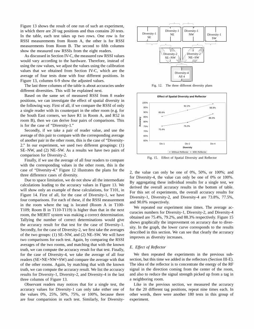
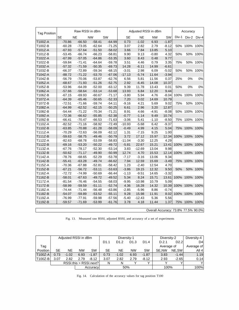
Figure13 shows the resultof onerun of suchan experiment,in whichS thereare20 tag positions andthuscontains 20 tests.In the table, each test takes up two rows. One row is forRSSI measurements from Room A, the other is for RSSImeasurements from Room B. The secondto fifth columnsshow the measured raw RSSIsfrom the eight readers.
As discussedin SectionIV-C, themeasuredraw RSSIvalueswould vary according to the hardware. Therefore, insteadofusingtheraw values,we adjustthevaluesusingthecalibrationvalues that we obtained from Section IV-C, which are theaverage of four tests done with four different positions. InFigure13, columns 6-9 show the adjustedvalues.
Thelastthreecolumnsof thetableis about accuraciesunderdifferent diversities.This will be explained next.
Basedon the sameset of measuredRSSI from 8 readerpositions,we can investigatethe effect of spatialdiversity inthefollowing way. First of all, if we compare theRSSIof onlya singlereaderwith its counterpartin the otherroom(e.g. forthe SouthEastcorners,we have R1 in RoomA, andR52 inroom B), thenwe canderive four pairsof comparisons.Thisis for the caseof “Di versity-1.”
Secondly, if we take a pair of readervalue, and use theaverage of this pair to compare with thecorresponding averageof anotherpair in theotherroom, this is thecaseof “Di versity-2.” In our experiment, we usedtwo different groupings: (1)SE–NW, and (2) NE–SW. As a resultswe have two pairs ofcomparisonfor Diversity-2.
Finally, if we usetheaverage of all four readersto comparewith the corresponding values in the other room, this is thecaseof “Di versity-4.” Figure 12 illustratesthe plans for thethreedifferencecasesof diversity.
Dueto spacelimitation, we do not show all theintermediatecalculations leading to the accuracy values in Figure 13. Wewill show only an example of thesecalculations, for T101, inFigure 14. First of all, for the caseof Diversity-1, we havefour comparisons.For eachof these,if theRSSImeasurementin the room where the tag is located (Room A in T100-T109; RoomB in T110-T119) is higher thanthat in the nextroom, theMERIT systemwasmaking a correctdetermination.Tallying the number of correct determinations would givethe accuracy result for that test for the caseof Diversity-1.Secondly, for thecaseof Diversity-2, we first take theaveragesof the two groups: (1) SE–NW, and(2) NE–SW. We will havetwo comparisonsfor eachtest.Again, by comparing theRSSIaveragesof the two rooms, andmatchingthatwith theknowntruth,we cancompute theaccuracy resultfor that test.Finally,for the caseof Diversity-4, we take the average of all fourreaders (SE+NE+NW+SW)andcomparetheaveragewith thatof the other rooms. Again, by matching that with the knowntruth,we cancomputetheaccuracy result.We list theaccuracyresultsfor Diversity-1, Diversity-2, andDiversity-4 in the lastthreecolumns of Figure13.
Observant readers may notices that for a single test, theaccuracy valuesfor Diversity-1 can only take either one ofthe values 0%, 25%, 50%, 75%, or 100%, becausethereare four comparision in each test. Similarly, for Diversity-
Diversity-4All 4
Diversity-2SE--NW
Diversity-1SE
Diversity-2NE--SW
Diversity-1NE
Diversity-1NW Diversity-1
SW
Fig. 12. The threedifferent diversity plans
Effect of Spatial Diversity and Reflector
88.3%
79.2%
75.4%
98.9%92.2%
85.6%
60%
65%
70%
75%
80%
85%
90%
95%
100%
Div-1 Div-2 Div-4
Diversity
Acc
ura
cy
Without Reflector With Reflector
Fig. 15. Effect of Spatial Diversity andReflector
2, the value can only be one of 0%, 50%, or 100%; andfor Diversity-4, the value can only be one of 0% or 100%.By aggregating theseindividual resultsfor a single test, wederived the overall accuracy results in the bottom of table.For this set of experiments, the overall accuracy results forDiversity-1, Diversity-2, and Diversity-4 are 73.8%, 77.5%,and90.0% respectively.
We repeated our experiment nine times. The average ac-curacies numbersfor Diversity-1, Diversity-2, andDiversity-4obtainedare75.4%, 79.2%,and88.3%respectively. Figure15shows graphically the improvement on accuracy dueto diver-sity. In the graph, the lower curve correspondsto the resultsdescribed in this section.We canseethatclearly theaccuracyimprovesasdiversity increases.
E. Effect of Reflector
We then repeated the experiments in the previous sub-section,but this time weaddedin thereflectors(SectionIII-E).Theideaof thereflectoris to concentratetheenergy of theRFsignal in the direction coming from the centerof the room,andalsoto reducethe signalstrengthpickedup from a tag ina neighboring room.
Like in the previous section, we measuredthe accuracyfor the 20 different tag positions,repeatnine times each.Inother words, there were another 180 tests in this group ofexperiment.
SE NE NW SW SE NE NW SW Div-1 Div-2 Div-4T100Z-A -70.86 -66.50 -58.41 -64.99 0.73 -1.02 6.93 -1.87T100Z-B -60.28 -73.05 -62.64 -71.25 3.07 2.82 2.79 -8.12 50% 100% 100%T101Z-A -67.93 -57.64 -51.50 -58.02 3.66 7.84 13.85 5.10T101Z-B -53.45 -66.74 -66.23 -58.81 9.90 9.13 -0.80 4.32 50% 50% 100%T102Z-A -67.99 -57.05 -64.86 -53.35 3.60 8.43 0.48 9.77T102Z-B -59.84 -71.41 -64.64 -59.78 3.51 4.46 0.79 3.35 75% 50% 100%T103Z-A -57.32 -71.59 -50.35 -69.73 14.28 -6.11 14.99 -6.61T103Z-B -66.37 -72.89 -59.34 -68.15 -3.01 2.98 6.09 -5.02 50% 50% 100%T104Z-A -88.72 -71.22 -53.70 -67.06 -17.13 -5.74 11.64 -3.94T104Z-B -56.79 -70.06 -53.87 -62.76 6.56 5.81 11.56 0.37 25% 0% 0%T105Z-A -68.67 -71.93 -51.26 -52.75 2.92 -6.45 14.08 10.37T105Z-B -53.96 -64.09 -52.00 -63.12 9.39 11.78 13.43 0.01 50% 0% 0%T106Z-A -57.66 -58.64 -53.14 -53.68 13.93 6.84 12.20 9.44T106Z-B -67.15 -69.93 -60.67 -71.17 -3.80 5.94 4.76 -8.04 100% 100% 100%T107Z-A -64.39 -65.46 -50.65 -52.33 7.20 0.02 14.69 10.79T107Z-B -72.51 -71.66 -59.74 -54.11 -9.16 4.21 5.69 9.02 75% 50% 100%T108Z-A -64.99 -62.52 -62.15 -50.25 6.61 2.96 3.20 12.87T108Z-B -54.44 -71.22 -70.34 -71.21 8.91 4.66 -4.91 -8.08 50% 100% 100%T109Z-A -72.36 -66.62 -55.85 -52.38 -0.77 -1.14 9.49 10.74T109Z-B -66.41 -70.47 -66.53 -71.63 -3.06 5.41 -1.10 -8.50 75% 100% 100%T110Z-A -82.52 -71.16 -58.92 -72.49 -10.93 -5.68 6.42 -9.37T110Z-B -63.85 -70.88 -61.28 -58.09 -0.49 4.99 4.15 5.04 75% 100% 100%T111Z-A -70.29 -72.63 -56.09 -62.12 1.31 -7.15 9.25 1.00T111Z-B -59.63 -58.75 -49.46 -50.79 3.72 17.12 15.97 12.34 100% 100% 100%T112Z-A -82.63 -68.78 -53.09 -58.83 -11.04 -3.30 12.25 4.29T112Z-B -69.16 -53.20 -50.22 -49.72 -5.81 22.67 15.21 13.41 100% 100% 100%T113Z-A -67.76 -78.17 -52.30 -53.14 3.83 -12.69 13.04 9.98T113Z-B -50.62 -71.17 -49.90 -50.99 12.74 4.70 15.53 12.14 100% 100% 100%T114Z-A -78.76 -68.65 -52.29 -53.78 -7.17 -3.16 13.06 9.34T114Z-B -55.41 -63.28 -49.74 -66.62 7.94 12.59 15.69 -3.49 75% 100% 100%T115Z-A -70.36 -67.88 -52.81 -58.42 1.23 -2.40 12.54 4.70T115Z-B -67.21 -56.72 -53.11 -53.63 -3.86 19.15 12.32 9.50 50% 50% 100%T116Z-A -72.72 -74.99 -50.69 -66.44 -1.13 -9.51 14.65 -3.32T116Z-B -58.01 -67.63 -49.72 -49.52 5.34 8.24 15.71 13.61 100% 100% 100%T117Z-A -81.54 -76.46 -54.55 -58.03 -9.95 -10.98 10.79 5.09T117Z-B -58.99 -59.59 -51.11 -52.74 4.36 16.28 14.32 10.39 100% 100% 100%T118Z-A -74.44 -71.44 -56.48 -63.86 -2.85 -5.96 8.86 -0.74T118Z-B -54.07 -59.89 -53.52 -55.11 9.28 15.98 11.91 8.02 100% 100% 100%T119Z-A -76.99 -77.91 -59.98 -57.56 -5.40 -12.43 5.36 5.56T119Z-B -59.57 -71.69 -53.99 -61.76 3.78 4.18 11.44 1.37 75% 100% 100%
73.8% 77.5% 90.0%Overall Accuracy:
Tag PositionRaw RSSI in dBm Adjusted RSSI in dBm Accuracy
Fig. 13. Measuredraw RSSI,adjusted RSSI,and accuracy of a setof experiments
Diversity-4D1.1 D1.2 D1.3 D1.4 D.2.1 D2.2 D4
Average ofSE NE NW SW SE NE NW SW SE,NW NE,SW All 4
T100Z-A 0.73 -1.02 6.93 -1.87 0.73 -1.02 6.93 -1.87 3.83 -1.44 1.19T100Z-B 3.07 2.82 2.79 -8.12 3.07 2.82 2.79 -8.12 2.93 -2.65 0.14
N N Y Y Y Y Y100%
Tag Position
Accuracy 50% 100%
Diversity-1 Diversity-2
RSSI.this > RSSI.next?
Average of
Adjusted RSSI in dBm
Fig. 14. Calculation of the accuracy values for tag position T100
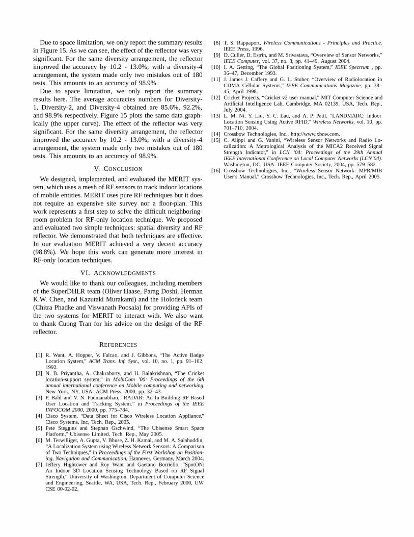
Dueto spacelimitation, we only report thesummaryresultsin Figure15.As wecansee,theeffectof thereflectorwasverysignificant.For the samediversity arrangement,the reflectorimproved the accuracy by 10.2 - 13.0%; with a diversity-4arrangement,the systemmadeonly two mistakes out of 180tests.This amounts to an accuracy of 98.9%.
Due to space limitation, we only report the summaryresultshere.The averageaccuraciesnumbers for Diversity-1, Diversity-2, and Diversity-4 obtained are 85.6%, 92.2%,and98.9%respectively. Figure15 plots the samedatagraph-ically (the upper curve). The effect of the reflectorwas verysignificant.For the samediversity arrangement,the reflectorimproved the accuracy by 10.2 - 13.0%; with a diversity-4arrangement,the systemmadeonly two mistakes out of 180tests.This amounts to an accuracy of 98.9%.
V. CONCLUSION
We designed, implemented,andevaluatedthe MERIT sys-tem,whichusesameshof RF sensorsto trackindoor locationsof mobile entities.MERIT usespureRF techniquesbut it doesnot require an expensive site survey nor a floor-plan. Thiswork represents a first stepto solve the difficult neighboring-room problem for RF-only location technique. We proposedandevaluatedtwo simpletechniques:spatialdiversity andRFreflector. We demonstratedthat both techniquesareeffective.In our evaluation MERIT achieved a very decent accuracy(98.8%). We hope this work can generatemore interest inRF-only locationtechniques.
VI . ACKNOWLEDGMENTS
We would like to thankour colleagues,including membersof theSuperDHLR team(Oliver Haase,ParagDoshi,HermanK.W. Chen,andKazutaki Murakami) andthe Holodeck team(ChitraPhadke andViswanathPoosala)for providing APIs ofthe two systemsfor MERIT to interact with. We also wantto thankCuongTran for his adviceon the designof the RFreflector.
REFERENCES
[1] R. Want, A. Hopper, V. Falcao, and J. Gibbons,“The Active BadgeLocation System,” ACM Trans. Inf. Syst., vol. 10, no. 1, pp. 91–102,1992.
[2] N. B. Priyantha, A. Chakraborty, and H. Balakrishnan, “The Cricketlocation-support system,” in MobiCom ’00: Proceedings of the 6thannual international conferenceon Mobile computing and networking.New York, NY, USA: ACM Press,2000,pp. 32–43.
[3] P. Bahl and V. N. Padmanabhan, “RADAR: An In-Building RF-BasedUser Location and Tracking System.” in Proceedings of the IEEEINFOCOM 2000, 2000,pp. 775–784.
[4] Cisco System,“Data Sheet for Cisco Wireless Location Appliance,”Cisco Systems,Inc, Tech.Rep.,2005.
[5] Pete Steggles and StephanGschwind, “The Ubisense Smart SpacePlatform,” UbisenseLimited, Tech.Rep.,May 2005.
[6] M. Terwill iger, A. Gupta, V. Bhuse,Z. H. Kamal,andM. A. Salahuddin,“A Localization SystemusingWirelessNetwork Sensors:A Comparisonof Two Techniques,” in Proceedingsof the First Workshopon Position-ing, Navigation and Communication, Hannover, Germany, March 2004.
[7] Jeffery Hightower and Roy Want and Gaetano Borriello, “SpotON:An Indoor 3D Location Sensing Technology Based on RF SignalStrength,” University of Washington, Department of Computer Scienceand Engineering, Seattle, WA, USA, Tech. Rep., February 2000, UWCSE00-02-02.
[8] T. S. Rappaport, WirelessCommunications - Principles and Practice.IEEE Press,1996.
[9] D. Culler, D. Estrin,andM. Srivastava, “Overview of SensorNetworks,”IEEE Computer, vol. 37, no. 8, pp. 41–49,August2004.
[10] I. A. Getting, “The Global Positioning System,” IEEE Spectrum , pp.36–47,December 1993.
[11] J. JamesJ. Caffery and G. L. Stuber, “Overview of Radiolocation inCDMA Cellular Systems,” IEEE Communications Magazine, pp. 38–45, April 1998.
[12] Cricket Projects, “Cricket v2 usermanual,” MIT Computer Science andArtifici al Intelligence Lab, Cambridge, MA 02139, USA, Tech. Rep.,July 2004.
[13] L. M. Ni, Y. Liu, Y. C. Lau, and A. P. Patil, “LANDMARC: IndoorLocation SensingUsing Active RFID,” WirelessNetworks, vol. 10, pp.701–710,2004.
[14] Crossbow Technologies, Inc., http://www.xbow.com.[15] C. Alippi and G. Vanini, “WirelessSensorNetworks and Radio Lo-
calization: A Metrological Analysis of the MICA2 Received SignalStrength Indicator,” in LCN ’04: Proceedings of the 29th AnnualIEEE International Conferenceon Local ComputerNetworks(LCN’04).Washington, DC, USA: IEEE Computer Society, 2004,pp. 579–582.
[16] Crossbow Technologies, Inc., “Wireless SensorNetwork: MPR/MIBUser’s Manual,” Crossbow Technologies,Inc., Tech.Rep.,April 2005.