Embed Size (px)
Citation preview
Chapter 19
Voice administration—an overview
In this chapter
Voice Administration 19-2
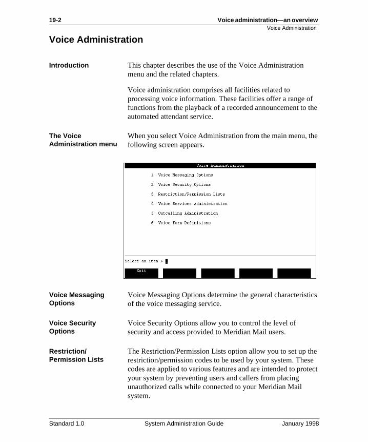
19-2 Voice administration—an overview Voice Administration
f the
he
tics
he se tect
Voice Administration
Introduction This chapter describes the use of the Voice Administration menu and the related chapters.
Voice administration comprises all facilities related to processing voice information. These facilities offer a range ofunctions from the playback of a recorded announcement to automated attendant service.
The Voice Administration menu
When you select Voice Administration from the main menu, tfollowing screen appears.
Voice Messaging Options
Voice Messaging Options determine the general characterisof the voice messaging service.
Voice Security Options
Voice Security Options allow you to control the level of security and access provided to Meridian Mail users.
Restriction/Permission Lists
The Restriction/Permission Lists option allow you to set up trestriction/permission codes to be used by your system. Thecodes are applied to various features and are intended to proyour system by preventing users and callers from placing unauthorized calls while connected to your Meridian Mail system.
Standard 1.0 System Administration Guide January 1998
Voice administration—an overview 19-3Voice Administration
ted g
nd
d f as
Voice Services Administration
The Voice Services Administration option allows you to
• add service DNs to the system and maintain existing DNinformation
• create a Voice Services profile
• create and maintain services such as
— Announcements
— Thru-Dial services
— Voice Menus
— Time-of-Day controllers
— Fax item definitions (if Fax on Demand is installed)
These services offer a range of functions from the simple playback of a recorded announcement to the more sophisticavoice menus which allow callers to make choices by pressinkeys on their telephone keypads.
Outcalling Administration
The Outcalling Administration option allows you to specify outcalling parameters which affect the Remote Notification aDelivery to Non-user feature.
This option is displayed only if the outcalling feature is installed.
Voice Form Definitions
The Voice Form Definitions option allows you to develop custom applications that ask specific questions of callers ancollect their responses. These applications can be thought othe electronic equivalent of a survey or questionnaire.
This option is displayed only if the voice forms feature is installed.
Standard 1.0 System Administration Guide January 1998
19-4 Voice administration—an overview Voice Administration
u
s
Related chapters The following table describes which chapter or document yoshould refer to when using one of the Voice Administration menu options.
Related information Display optionsThe [Display Options] softkey is available from Voice ServiceAdministration. The Display Options screen allows you to customize the Voice Services Administration screens.
See Chapter 21, “Display options. ”
Finding VSDNs and servicesWithin Voice Administration, you can use the find function tofind a specific VSDN or voice or fax service, or a subset of VSDNs or voice and fax services.
See Chapter 22, “Finding and printing VSDNs and service definitions. ”
For the following option See
Voice Messaging Options Chapter 20, "Voice messaging options".
Voice Security Options Chapter 6, "Setting up Meridian Mail security".
Restriction/Permission Lists Section H: Restriction/Permission lists in Chapter 6, "Setting up Meridian Mail security".
Voice Services Administration Chapter 21, "Display options".
Outcalling Administration Outcalling Application Guide (NTP 555-7001-320).
Voice Form Definitions Voice Services Application Guide
(NTP 555-7001-325).
Standard 1.0 System Administration Guide January 1998
Voice administration—an overview 19-5Voice Administration
Configuring Meridian Mail servicesConfiguring Meridian Mail services involves setup on the Meridian 1 and in Meridian Mail.
For information about how to configure the Meridian 1 to support Meridian Mail services, see Chapter 23, “ConfiguringMeridian Mail services”.
Standard 1.0 System Administration Guide January 1998

19-6 Voice administration—an overview Voice Administration
Standard 1.0 System Administration Guide January 1998
Chapter 20
Voice messaging options
In this chapter
Section A: Introduction 20-3
Section B: Languages on multilingual systems 20-11
Section C: Customizing recordings 20-27
Section D: Defining operational characteristics for voice messaging
20-37

20-2 Voice messaging options
Standard 1.0 System Administration Guide January 1998
Voice messaging options 20-3
Section A: Introduction
In this section
Overview 20-4
Accessing the Voice Messaging Options screen 20-5
The Voice Messaging Options screen 20-6
Defining voice messaging options 20-9
Standard 1.0 System Administration Guide January 1998
20-4 Voice messaging options Overview
up :
ch nal al
nd
ing
ept
ir
Overview
Introduction Setting up voice messaging options for your system involvesthe following tasks.
Setting up languages If you have more than one language installed, you must set certain language parameters. This is described in Section BLanguages on multilingual systems.
Customizing recordings
You can customize the following recordings:
• the call answering greeting (for MMUI)
• the VMUIF introductory tutorial (for VMUIF)
• the VMUIF login greeting
This is described in Section C: Customizing recordings.
Enabling features You can enable/disable certain voice messaging features suas timed delivery, name dialing/name addressing, and extercall sender. This is described in Section D: Defining operationcharacteristics for voice messaging.
Setting up the broadcast mailbox
The broadcast mailbox is set up in the Voice Messaging Options screen. This involves assigning a mailbox number arecording a personal verification (the verification is optional).This is described in Section D: Defining operational characteristics for voice messaging.
Defining operational characteristics
You can define operational characteristics for voice messagsuch as
• the maximum number of days that read messages are kbefore being deleted
• whether a warning message is played to users when themailbox is almost full, and when this message is played
• the billing DN
This is described in Section D: Defining operational characteristics for voice messaging.
Standard 1.0 System Administration Guide January 1998
Voice messaging options 20-5Accessing the Voice Messaging Options screen
ice is
e
Accessing the Voice Messaging Options screen
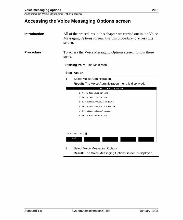
Introduction All of the procedures in this chapter are carried out in the VoMessaging Options screen. Use this procedure to access thscreen.
Procedure To access the Voice Messaging Options screen, follow thessteps.
Starting Point: The Main Menu
Step Action
1 Select Voice Administration.
Result: The Voice Administration menu is displayed.
2 Select Voice Messaging Options.
Result: The Voice Messaging Options screen is displayed.
Standard 1.0 System Administration Guide January 1998
20-6 Voice messaging options The Voice Messaging Options screen
The Voice Messaging Options screen
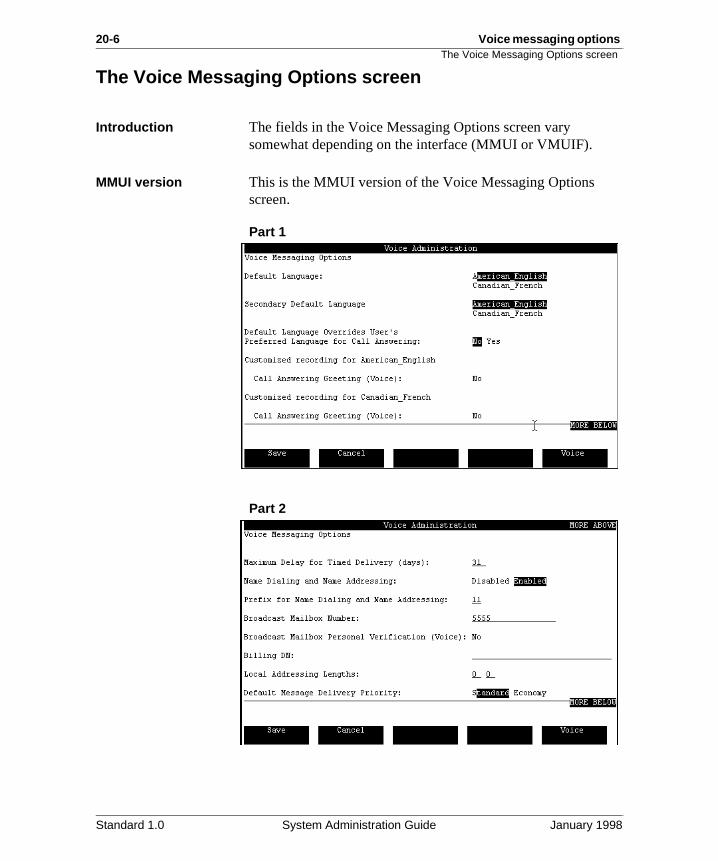
Introduction The fields in the Voice Messaging Options screen vary somewhat depending on the interface (MMUI or VMUIF).
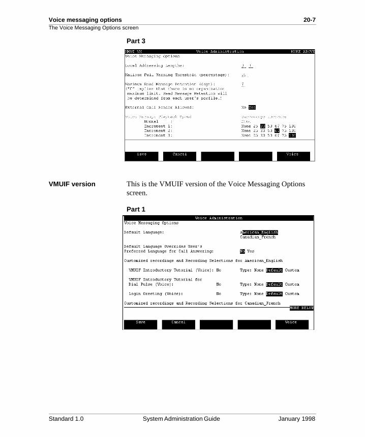
MMUI version This is the MMUI version of the Voice Messaging Options screen.
Part 1
Part 2
Standard 1.0 System Administration Guide January 1998
Voice messaging options 20-7The Voice Messaging Options screen
Part 3
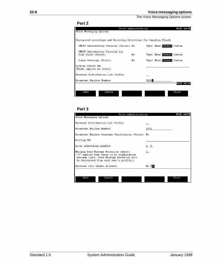
VMUIF version This is the VMUIF version of the Voice Messaging Options screen.
Part 1
Standard 1.0 System Administration Guide January 1998
20-8 Voice messaging options The Voice Messaging Options screen
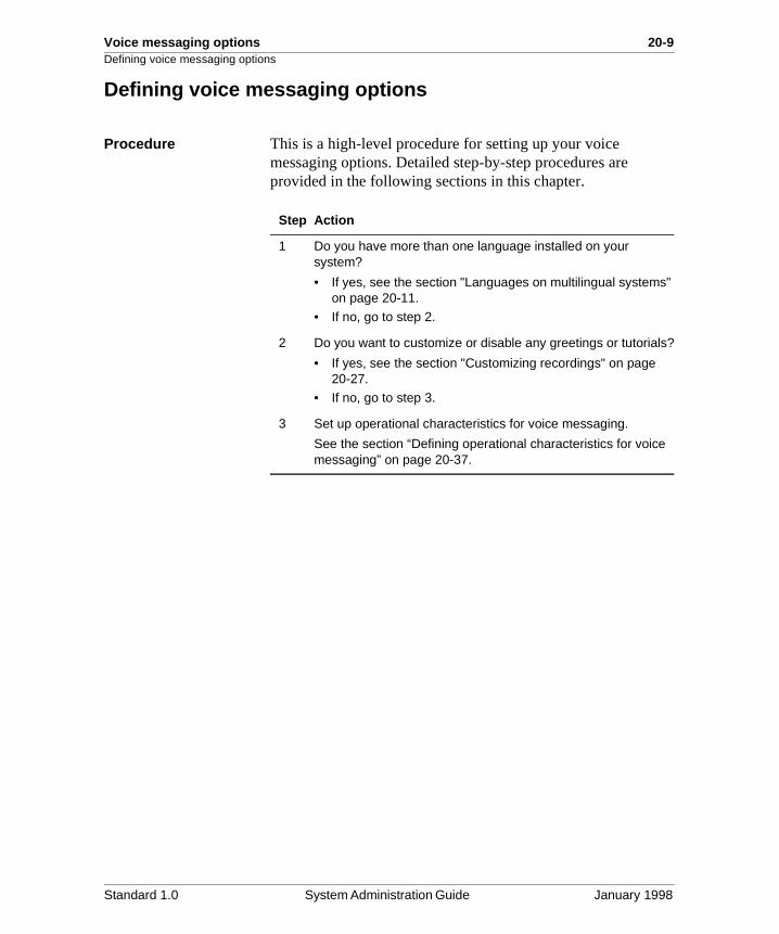
Part 2
Part 3
Standard 1.0 System Administration Guide January 1998
Voice messaging options 20-9Defining voice messaging options
Defining voice messaging options
Procedure This is a high-level procedure for setting up your voice messaging options. Detailed step-by-step procedures are provided in the following sections in this chapter.
Step Action
1 Do you have more than one language installed on your system?
• If yes, see the section "Languages on multilingual systems" on page 20-11.
• If no, go to step 2.
2 Do you want to customize or disable any greetings or tutorials?
• If yes, see the section "Customizing recordings" on page 20-27.
• If no, go to step 3.
3 Set up operational characteristics for voice messaging.
See the section “Defining operational characteristics for voice messaging” on page 20-37.
Standard 1.0 System Administration Guide January 1998

20-10 Voice messaging options Defining voice messaging options
Standard 1.0 System Administration Guide January 1998
Voice messaging options 20-11
Section B: Languages on multilingual systems
In this section
Overview 20-12
The default language and the user’s preferred language 20-13
Setting up languages on systems without dual language prompting
20-15
Setting up languages on systems with dual language prompting
20-19
Standard 1.0 System Administration Guide January 1998
20-12 Voice messaging options Overview
ther
Overview
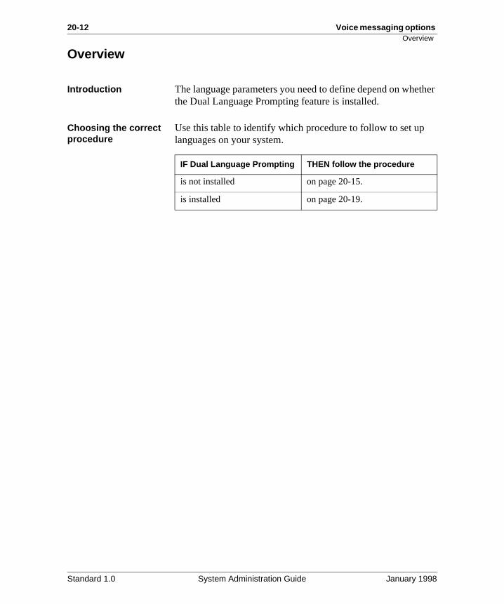
Introduction The language parameters you need to define depend on whethe Dual Language Prompting feature is installed.
Choosing the correct procedure
Use this table to identify which procedure to follow to set up languages on your system.
IF Dual Language Prompting THEN follow the procedure
is not installed on page 20-15.
is installed on page 20-19.
Standard 1.0 System Administration Guide January 1998
Voice messaging options 20-13The default language and the user’s preferred language
.
or box.
om d .
n
ed
nd
The default language and the user’s preferred language
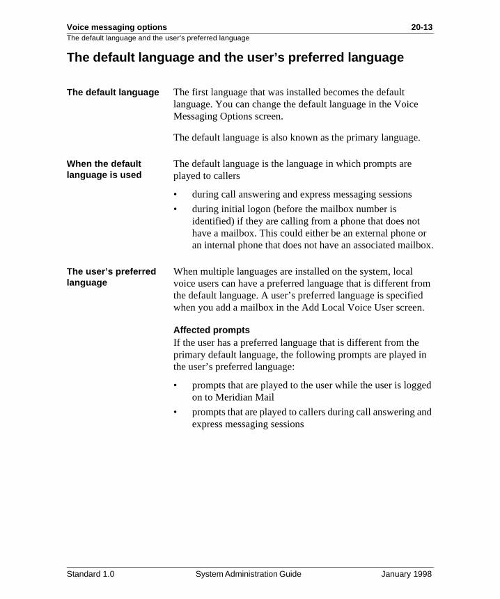
The default language The first language that was installed becomes the default language. You can change the default language in the VoiceMessaging Options screen.
The default language is also known as the primary language
When the default language is used
The default language is the language in which prompts are played to callers
• during call answering and express messaging sessions
• during initial logon (before the mailbox number is identified) if they are calling from a phone that does not have a mailbox. This could either be an external phone an internal phone that does not have an associated mail
The user’s preferred language
When multiple languages are installed on the system, local voice users can have a preferred language that is different frthe default language. A user’s preferred language is specifiewhen you add a mailbox in the Add Local Voice User screen
Affected promptsIf the user has a preferred language that is different from theprimary default language, the following prompts are played ithe user’s preferred language:
• prompts that are played to the user while the user is loggon to Meridian Mail
• prompts that are played to callers during call answering aexpress messaging sessions
Standard 1.0 System Administration Guide January 1998
20-14 Voice messaging options The default language and the user’s preferred language
re
ar
f
Overriding the user’s preferred language
You may not want internal or external callers, or both, who atransferred to Meridian Mail to hear prompts in the user’s preferred language. Instead, you might want them to hear prompts in the (primary) default language.
To ensure that callers who are forwarded to Meridian Mail heprompts in your system’s primary language, the Default Language Overrides User’s Preferred Language field in the Voice Messaging Options screen must be set to Yes. Users,however, still hear prompts in their preferred language whenthey log in to retrieve messages.
Example Your office is located in Vancouver, British Columbia. Many oyour employees speak Mandarin as their first language and,therefore, prefer to hear prompts in Mandarin while using Meridian Mail.
However, most of your customers and external callers are English-speaking and you want them to hear Meridian Mail prompts in English.
You, therefore, set the Default Language Overrides User’s Preferred Language field to Yes.
Standard 1.0 System Administration Guide January 1998
Voice messaging options 20-15Setting up languages on systems without dual language prompting
ge)
red
Setting up languages on systems without dual language prompting
Introduction To set up languages when Dual Language Prompting is not installed, you must specify
• the default language (also known as the primary langua
• whether the default language overrides the user’s preferlanguage
Standard 1.0 System Administration Guide January 1998
20-16 Voice messaging options Setting up languages on systems without dual language prompting
ed
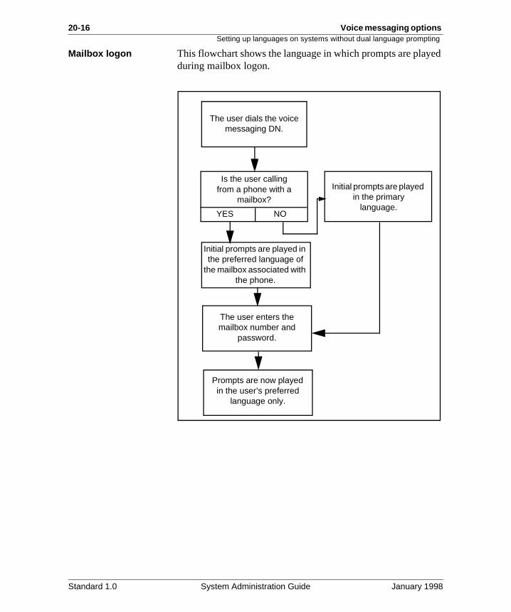
Mailbox logon This flowchart shows the language in which prompts are playduring mailbox logon.The user dials the voicemessaging DN.
Is the user callingfrom a phone with a
mailbox?
YES NO
Initial prompts are played in the preferred language of
the mailbox associated with the phone.
Initial prompts are played in the primary
language.
The user enters the mailbox number and
password.
Prompts are now played in the user’s preferred
language only.
Standard 1.0 System Administration Guide January 1998
Voice messaging options 20-17Setting up languages on systems without dual language prompting
ther
the
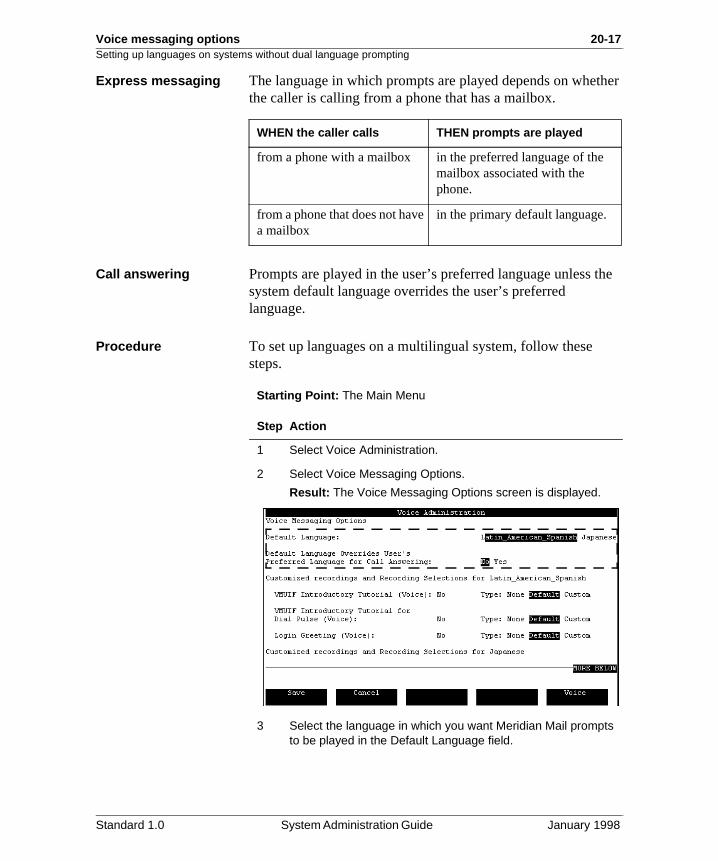
Express messaging The language in which prompts are played depends on whethe caller is calling from a phone that has a mailbox.
Call answering Prompts are played in the user’s preferred language unless system default language overrides the user’s preferred language.
Procedure To set up languages on a multilingual system, follow these steps.
Starting Point: The Main Menu
WHEN the caller calls THEN prompts are played
from a phone with a mailbox in the preferred language of the mailbox associated with the phone.
from a phone that does not have a mailbox
in the primary default language.
Step Action
1 Select Voice Administration.
2 Select Voice Messaging Options.
Result: The Voice Messaging Options screen is displayed.
3 Select the language in which you want Meridian Mail prompts to be played in the Default Language field.
Standard 1.0 System Administration Guide January 1998
20-18 Voice messaging options Setting up languages on systems without dual language prompting
4 Do you want the (primary) default language to override users’ preferred languages?
• If yes, select Yes in the Default Language Overrides User’s Preferred Language field.
• If no, select No.
5 Do you want to continue defining voice messaging options?
Step Action
IF you want to THEN
customize or disable recordings
see the section "Customizing recordings" on page 20-27.
modify other voice messaging options
see the section "Defining operational characteristics for voice messaging" on page 20-37.
save what you have done and quit
press [Save].
quit without saving press [Cancel].
Standard 1.0 System Administration Guide January 1998
Voice messaging options 20-19Setting up languages on systems with dual language prompting
re
e
ge)
red
e a
ors
e
ver, s
Setting up languages on systems with dual language prompting
Description: dual language prompting
Dual Language Prompting is an optional Meridian Mail featuthat is intended for bilingual environments. When installed, prompts are played in two languages:
• the primary language followed by the secondary languagor
• the primary language followed by the user’s preferred language
Configuration requirements
If Dual Language Prompting is installed on your system, youmust specify
• the default language (also known as the primary langua
• the secondary language
• whether the default language overrides the user’s preferlanguage
The secondary default language
When Dual Language Prompting is installed, you can choossecondary default language in which to play prompts for callanswering, express messaging, and mailbox login.
How this secondary language is used depends on other factas described in more detail on the following pages.
DefaultBy default, the secondary language is set to the first languagthat was installed. After installation, the secondary default language is, therefore, the same as the (primary) default language.
How it works Dual language prompting affects how prompts are played during express messaging, logon, and call answering. Howefor each of these features, different factors affect how it workas described on the following pages.
Standard 1.0 System Administration Guide January 1998
20-20 Voice messaging options Setting up languages on systems with dual language prompting
s n
x,
,
r .
s he
Known versus unknown callers
For express messaging, whether the caller to the service is known affects how dual language prompting works. What is really meant by a “known caller” is a caller whose preferred language is known. In the case of an “unknown caller,” the caller’s preferred language is not known.
Known callersA caller is known when calling from an internal phone that haa mailbox associated with it. When calling from his or her owphone, the caller’s preferred language is known. When the caller is calling from another internal phone that has a mailbothe caller’s preferred language is not known. However, the preferred language for the associated mailbox is known andtherefore, the caller is considered to be known.
Unknown callersA caller is unknown when calling from a phone that does nothave an associated mailbox (and, therefore, no preferred language associated with it).
An unknown caller could be calling from an external phone oan internal phone that does not have an associated mailbox
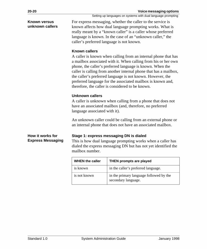
How it works for Express Messaging
Stage 1: express messaging DN is dialedThis is how dual language prompting works when a caller hadialed the express messaging DN but has not yet identified tmailbox number.
WHEN the caller THEN prompts are played
is known in the caller’s preferred language.
is not known in the primary language followed by the secondary language.
Standard 1.0 System Administration Guide January 1998
Voice messaging options 20-21Setting up languages on systems with dual language prompting
as
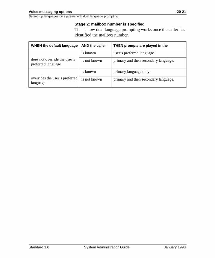
Stage 2: mailbox number is specifiedThis is how dual language prompting works once the caller hidentified the mailbox number.WHEN the default language AND the caller THEN prompts are played in the
does not override the user’s preferred language
is known user’s preferred language.
is not known primary and then secondary language.
overrides the user’s preferred language
is known primary language only.
is not known primary and then secondary language.
Standard 1.0 System Administration Guide January 1998
20-22 Voice messaging options
ot
Setting up languages on systems with dual language prompting
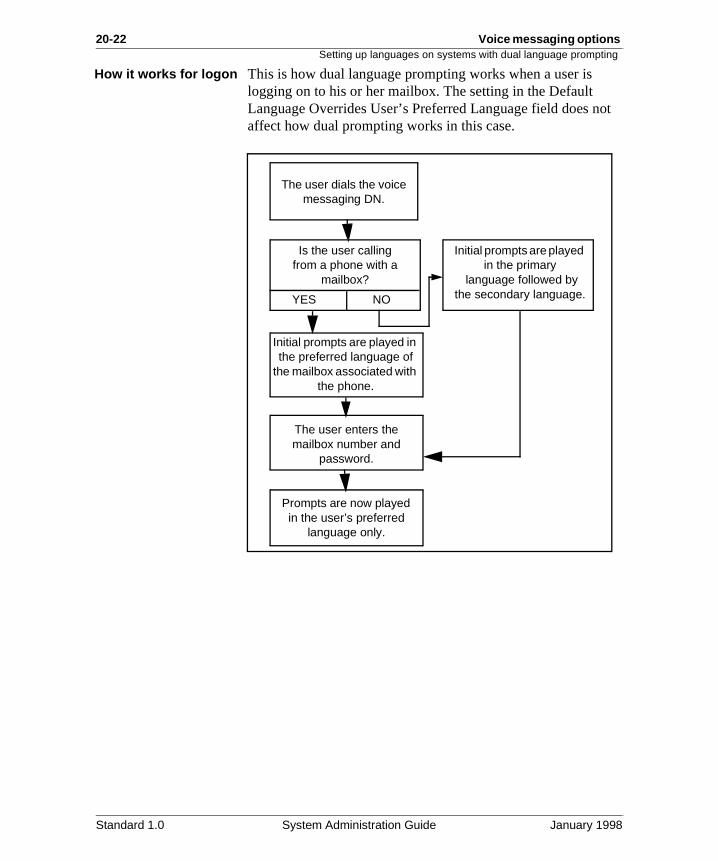
How it works for logon This is how dual language prompting works when a user is logging on to his or her mailbox. The setting in the Default Language Overrides User’s Preferred Language field does naffect how dual prompting works in this case.
The user dials the voicemessaging DN.
Is the user callingfrom a phone with a
mailbox?
YES NO
Initial prompts are played in the preferred language of
the mailbox associated with the phone.
Initial prompts are played in the primary
language followed by the secondary language.
The user enters the mailbox number and
password.
Prompts are now played in the user’s preferred
language only.
Standard 1.0 System Administration Guide January 1998
Voice messaging options 20-23Setting up languages on systems with dual language prompting
’s
’s
Configuring dual language prompting for call answering
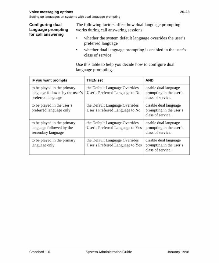
The following factors affect how dual language prompting works during call answering sessions:
• whether the system default language overrides the userpreferred language
• whether dual language prompting is enabled in the userclass of service
Use this table to help you decide how to configure dual language prompting.
IF you want prompts THEN set AND
to be played in the primary language followed by the user’s preferred language
the Default Language Overrides User’s Preferred Language to No
enable dual language prompting in the user’s class of service.
to be played in the user’s preferred language only
the Default Language Overrides User’s Preferred Language to No
disable dual language prompting in the user’s class of service.
to be played in the primary language followed by the secondary language
the Default Language Overrides User’s Preferred Language to Yes
enable dual language prompting in the user’s class of service.
to be played in the primary language only
the Default Language Overrides User’s Preferred Language to Yes
disable dual language prompting in the user’s class of service.
Standard 1.0 System Administration Guide January 1998
20-24 Voice messaging options Setting up languages on systems with dual language prompting
Setting up languages for dual language prompting
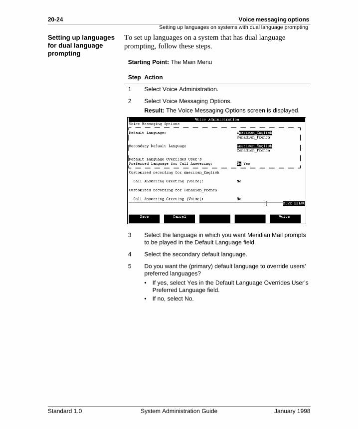
To set up languages on a system that has dual language prompting, follow these steps.
Starting Point: The Main Menu
Step Action
1 Select Voice Administration.
2 Select Voice Messaging Options.
Result: The Voice Messaging Options screen is displayed.
3 Select the language in which you want Meridian Mail prompts to be played in the Default Language field.
4 Select the secondary default language.
5 Do you want the (primary) default language to override users’ preferred languages?
• If yes, select Yes in the Default Language Overrides User’s Preferred Language field.
• If no, select No.
Standard 1.0 System Administration Guide January 1998
Voice messaging options 20-25Setting up languages on systems with dual language prompting
6 What do you want to do next?
Step Action
IF you want to THEN
customize or disable recordings
see the section "Customizing recordings" on page 20-27.
modify other voice messaging options
see the section "Defining operational characteristics for voice messaging" on page 20-37.
save what you have done and quit
press [Save].
quit without saving press [Cancel].
Standard 1.0 System Administration Guide January 1998

20-26 Voice messaging options Setting up languages on systems with dual language prompting
Standard 1.0 System Administration Guide January 1998
Voice messaging options 20-27
Section C: Customizing recordings
In this section
Overview 20-28
Recording a customized call answering greeting 20-29
VMUIF introductory tutorials and the VMUIF login greeting 20-32
Recording or disabling VMUIF tutorials and login greeting 20-34
Standard 1.0 System Administration Guide January 1998
20-28 Voice messaging options Overview
he
gs:
ls
, or
Overview
Introduction The recordings that you can customize differ depending on tinterface type (MMUI or VMUIF).
MMUI call answering greeting
If the interface is MMUI, you can record a custom call answering greeting that identifies your organization.
See “Recording a customized call answering greeting” on page 20-29.
VMUIF tutorials and greeting
If the interface is VMUIF, there are three associated recordin
• an introductory tutorial for touch-tone phone users
• an introductory tutorial for dial pulse phone users
• a greeting that is played to users when they log in to Meridian Mail
There are prerecorded (“canned”) recordings of these tutoriaand the login greeting that are enabled by default.
You can either use these default recordings, customize themdisable them altogether.
See “VMUIF introductory tutorials and the VMUIF login greeting” on page 20-32.
Standard 1.0 System Administration Guide January 1998
Voice messaging options 20-29Recording a customized call answering greeting
n
a
u
re ing
Recording a customized call answering greeting
Description The call answering greeting is an optional greeting for the MMUI interface. It typically consists of the spoken name of aorganization and is used to identify an organization to callersand users.
DefaultBy default, there is no call answering greeting. There is no generic call answering greeting. A custom greeting must be recorded if you want to use this greeting.
When the greeting is played
The call answering greeting is played when
• an external caller is transferred to Meridian Mail to leavemessage (call answering)
• a user answers a remote notification call
Multilingual systems If more than one language is installed on your Meridian Mailsystem and you want to record a call answering greeting, yoneed to record one greeting for each language.
Before you begin You must access the Voice Messaging Options screen befobeginning the following procedure. The procedure for accessthis screen is on page 20-5.
Standard 1.0 System Administration Guide January 1998
20-30 Voice messaging options Recording a customized call answering greeting
Procedure To record a call answering greeting, follow these steps.
Starting Point: The Voice Messaging Options screen
Step Action
1 Move the cursor to the (first) Call Answering Greeting (Voice) field.
2 Press the [Voice] softkey.
Result: The recording softkeys are displayed, and you are prompted for an extension number.
3 Enter the extension of the phone you will use to make the recording.
Result: The phone rings.
4 Pick up the handset.
5 Press the [Record] softkey.
Result: The [Stop] softkey is displayed.
6 Speak the call answering greeting and press [Stop] when you are done.
Note: Recording stops automatically if the greeting exceeds the Maximum Prompt Size or the Record Timeout set in the Voice Services Profile.
7 Do you want to verify the recording?
• If yes, press the [Play] softkey.
• If no, go to step 9.
Standard 1.0 System Administration Guide January 1998
Voice messaging options 20-31Recording a customized call answering greeting
8 Do you want to rerecord the greeting?
• If yes, repeat steps 5 to 7 until you are satisfied with the greeting.
Note: The old recording will be recorded over.
• If no, go to step 9.
9 Do you have more than one language installed?
• If yes, press the [Return] softkey to return to the Voice Messaging Options screen and go to step 10.
Note: Do not hang up the phone.
• If no, go to step 11.
10 Move your cursor to the next Call Answering Greeting field (for the next language), and repeat steps 2 to 7 until a greeting has been recorded for each language.
11 Press the [Disconnect] softkey and hang up the phone.
12 Do you want to change any other voice messaging options?
• If yes, see the section "Defining operational characteristics for voice messaging" on page 20-37.
• If no, press the [Save] softkey.
Step Action
Standard 1.0 System Administration Guide January 1998
20-32 Voice messaging options VMUIF introductory tutorials and the VMUIF login greeting
ize
s es. r, if our be ht p
VMUIF introductory tutorials and the VMUIF login greeting
Introduction There are three recordings for the VMUIF interface:
• the introductory tutorial (for touch-tone users)
• the introductory tutorial (for dial-pulse users)
• the login greeting
Prerecorded (“canned”) versions of these recordings are provided. These default recordings are enabled by default.
You can either use these default canned recordings, customthem, or disable them altogether.
The VMUIF introductory tutorials
When the tutorial is playedThis introductory tutorial is played to users when they log onfor the first time to familiarize them with the service.
The default (touch-tone) tutorial This is the prerecorded tutorial (for touch-tone users) that is enabled by default:
“You are about to hear an introduction to call answering. Thiservice will allow your callers to leave you recorded messagYou can play back your messages from your home phone oyou create a password, from any touch-tone phone outside yhome. You can also record a personalized greeting that will played to your callers, and you can erase your messages rigaway or store them temporarily in your mailbox. Step-by-steinstructions will guide you through your sessions. And remember, for help at any time, just press zero.”
Standard 1.0 System Administration Guide January 1998
Voice messaging options 20-33VMUIF introductory tutorials and the VMUIF login greeting
is es. ny
ult:
ls
The VMUIF introductory tutorials (cont’d)
The default dial-pulse tutorial This is the prerecorded tutorial for dial pulse users that is enabled by default:
“You are about to hear an introduction to call answering. Thservice will allow your callers to leave you recorded messagYou can listen to your messages from your home phone at atime. You can also play your messages from any touch-tonephone. And by calling the Greeting Change Service, you canrecord a personalized greeting that will be played to your callers. Step-by-step instructions will guide you through yoursessions. Consult the brochure for more information.”
The login greeting When the greeting is playedThe login greeting is played to users when they log in to Meridian Mail.
The default login greetingThis is the prerecorded login greeting that is enabled by defa
“Welcome to call answering.”
Multilingual systems If more than one language is installed on your Meridian Mailsystem, you need to record a separate version of the tutoriaand login greeting for each installed language.
Standard 1.0 System Administration Guide January 1998
20-34 Voice messaging options Recording or disabling VMUIF tutorials and login greeting
e
re ing
.
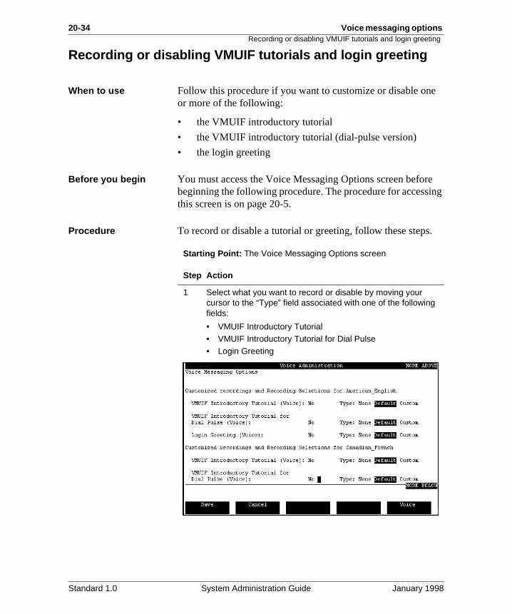
Recording or disabling VMUIF tutorials and login greeting
When to use Follow this procedure if you want to customize or disable onor more of the following:
• the VMUIF introductory tutorial
• the VMUIF introductory tutorial (dial-pulse version)
• the login greeting
Before you begin You must access the Voice Messaging Options screen befobeginning the following procedure. The procedure for accessthis screen is on page 20-5.
Procedure To record or disable a tutorial or greeting, follow these steps
Starting Point: The Voice Messaging Options screen
Step Action
1 Select what you want to record or disable by moving your cursor to the “Type” field associated with one of the following fields:
• VMUIF Introductory Tutorial• VMUIF Introductory Tutorial for Dial Pulse• Login Greeting
Standard 1.0 System Administration Guide January 1998
Voice messaging options 20-35Recording or disabling VMUIF tutorials and login greeting
2 Do you want to disable the tutorial or greeting?
• If yes, select None. Do this for each tutorial or greeting you want to disable.
• If no, go to step 3.
3 Do you want to record a custom tutorial or greeting?
• If yes, go to step 4.• If no, go to step 14.
4 Press the [Voice] softkey.
Result: You are prompted for the extension of the phone you want to use to make the recording.
5 Enter the extension and press <Return>.
Result: The phone rings.
6 Pick up the receiver.
Result: The recording softkeys are displayed.
7 Press the [Record] softkey.
8 At the sound of the beep, speak the greeting or tutorial.
9 Press the [Stop] softkey to stop recording.
10 Do you want to verify the recording?
• If yes, press the [Play] softkey, listen to the recording, and then go to step 11.
• If no, go to step 12.
11 Do you want to rerecord?
• If yes, press the [Record] softkey to rerecord the current recording until you are satisfied with the recording.
• If no, go to step 12.
12 Select Custom to enable the tutorial or greeting you recorded.
13 Do you want to record another tutorial or greeting?
• If yes, move the cursor to the appropriate tutorial or greeting field, and repeat steps 7 to 12 for each additional recording.
• If no, go to step 14.
14 Do you want to modify any other voice messaging options?
• If yes, see the section "Defining operational characteristics for voice messaging" on page 20-37.
• If no, press [Save].
Step Action
Standard 1.0 System Administration Guide January 1998

20-36 Voice messaging options Recording or disabling VMUIF tutorials and login greeting
Standard 1.0 System Administration Guide January 1998
Voice messaging options 20-37
Section D: Defining operational characteristics for voice messaging
In this section
Overview 20-38
Enabling/disabling timed delivery and name dialing/name addressing
20-40
Defining the lockout revert DN and personal distribution list prefix
20-45
Setting up the broadcast mailbox 20-47
Defining the billing DN 20-51
Specifying the message delivery priority for networked systems
20-53
Specifying the mailbox full warning threshold 20-55
Specifying the maximum read message retention 20-57
Enabling/disabling external call sender 20-60
Enabling and configuring speed control 20-62
Standard 1.0 System Administration Guide January 1998
20-38 Voice messaging options Overview
as
eir
an
Overview
Introduction This section describes
• how to enable or disable voice messaging features suchtimed delivery, name dialing/addressing, external call sender, and speed control
• how to set up a broadcast mailbox
• how to define voice messaging characteristics such as
- how long to store read messages
- whether to play a warning message to users when thmailbox is full
- when network messages should be deliverered
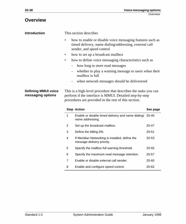
Defining MMUI voice messaging options
This is a high-level procedure that describes the tasks you cperform if the interface is MMUI. Detailed step-by-step procedures are provided in the rest of this section.
Step Action See page
1 Enable or disable timed delivery and name dialing/name addressing.
20-40
2 Set up the broadcast mailbox. 20-47
3 Define the billing DN. 20-51
4 If Meridian Networking is installed, define the message delivery priority.
20-53
5 Specify the mailbox full warning threshold. 20-55
6 Specify the maximum read message retention. 20-57
7 Enable or disable external call sender. 20-60
8 Enable and configure speed control. 20-62
Standard 1.0 System Administration Guide January 1998
Voice messaging options 20-39Overview
an
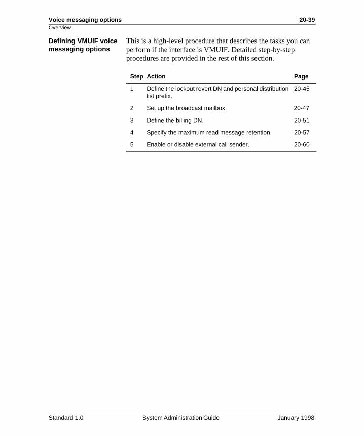
Defining VMUIF voice messaging optionsThis is a high-level procedure that describes the tasks you cperform if the interface is VMUIF. Detailed step-by-step procedures are provided in the rest of this section.
Step Action Page
1 Define the lockout revert DN and personal distribution list prefix.
20-45
2 Set up the broadcast mailbox. 20-47
3 Define the billing DN. 20-51
4 Specify the maximum read message retention. 20-57
5 Enable or disable external call sender. 20-60
Standard 1.0 System Administration Guide January 1998
20-40 Voice messaging options Enabling/disabling timed delivery and name dialing/name addressing
s to ay.
to r is
ge,
Enabling/disabling timed delivery and name dialing/name addressing
Introduction Timed delivery, name dialing, and name addressing are applicable to the MMUI interface only.
Timed delivery The timed delivery feature allows users to record a voice message now, but tag it for delivery at a later date.
The maximum timed delivery delay
In Voice Messaging Options, you can define the maximum number of days that a message can be delayed before beingdelivered. The default is 31 days.
ExampleYou have defined the maximum delay as 62 days. A user trietag his or her message for a delivery date of 75 days from todThe user hears the following message:
“The date you have entered is too far into the future. Pleasereenter the date.”
Name dialing and name addressing
Name dialing and name addressing allow users and callers dial or address users when the extension or mailbox numbenot known. As long as the caller knows the user’s name, theuser can be reached.
Name dialingName dialing allows users and callers who have accessed athru-dial service to enter a user’s name instead of his or her extension. The digits that the caller enters are interpreted asletters instead of numbers.
Name addressingName addressing allows users to enter another user’s nameinstead of a mailbox number when composing a voice messacomposing personal distribution lists, or when using expressmessaging.
Standard 1.0 System Administration Guide January 1998
Voice messaging options 20-41Enabling/disabling timed delivery and name dialing/name addressing
rs ls
uld
s
ow
to nd ne in
one le to
The name dialing/addressing prefix
If name dialing and name addressing are enabled, you mustdefine a prefix. This prefix must be entered by users or callebefore they begin entering the user’s name. This prefix signaMeridian Mail that the digits that are about to be entered shobe interpreted as letters instead of numbers.
Thru-dial servicesWhen defining a thru-dial service, you have the option of specifying the dialing method as Dial by Number, Dial by Name, or Both.
To select Dial by Name or Both, Name Dialing and Name Addressing must be enabled in the Voice Messaging Optionscreen.
If Both is selected, meaning that the caller has the choice of hhe or she dials the user, the caller must enter the prefix.
If you want to give callers this choice, but do not want them have to enter a prefix, you can use a voice menu as a front eto two thru-dialers (one that is set up for Dial by Name and othat is set up for Dial by Number). This is described in detailthe Voice Services Application Guide.
When to disable name dialing/addressing
This feature should be disabled in countries where the telephkeypads do not map to an alphabetical sequence recognizabMeridian Mail.
Standard 1.0 System Administration Guide January 1998
20-42 Voice messaging options Enabling/disabling timed delivery and name dialing/name addressing
e
an
.
e
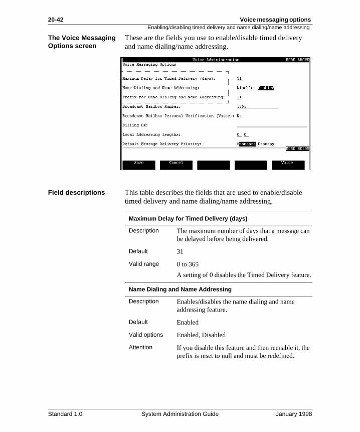
The Voice Messaging Options screen
These are the fields you use to enable/disable timed deliveryand name dialing/name addressing.
Field descriptions This table describes the fields that are used to enable/disabltimed delivery and name dialing/name addressing.
Maximum Delay for Timed Delivery (days)
Description The maximum number of days that a message cbe delayed before being delivered.
Default 31
Valid range 0 to 365
A setting of 0 disables the Timed Delivery feature
Name Dialing and Name Addressing
Description Enables/disables the name dialing and name addressing feature.
Default Enabled
Valid options Enabled, Disabled
Attention If you disable this feature and then reenable it, thprefix is reset to null and must be redefined.
Standard 1.0 System Administration Guide January 1998
Voice messaging options 20-43Enabling/disabling timed delivery and name dialing/name addressing
e
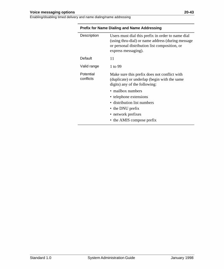
Prefix for Name Dialing and Name Addressing
Description Users must dial this prefix in order to name dial (using thru-dial) or name address (during messagor personal distribution list composition, or express messaging).
Default 11
Valid range 1 to 99
Potential conflicts
Make sure this prefix does not conflict with (duplicate) or underlap (begin with the same digits) any of the following:
• mailbox numbers
• telephone extensions
• distribution list numbers
• the DNU prefix
• network prefixes
• the AMIS compose prefix
Standard 1.0 System Administration Guide January 1998
20-44 Voice messaging options Enabling/disabling timed delivery and name dialing/name addressing
Procedure To enable/disable timed delivery or name dialing/name addressing, or both, follow these steps.
Starting Point: The Voice Messaging Options screen
Step Action
1 Do you want to disable timed delivery?
• If yes, enter 0 in the Maximum Delay for Timed Delivery field.
• If no, enter the maximum number of days you want users to be able to delay delivery of voice messages.
2 Do you want to disable name dialing and name addressing?
• If yes, select Disabled in the Name Dialing and Name Addressing field.
• If no, select Enabled.
3 Are name dialing and name addressing enabled?
• If yes, change the prefix if necessary.
• If no, go to step 4.
4 Do you want to continue defining voice messaging options?
IF you want to THEN
continue see page 20-47.
save your changes and quit press [Save].
quit without saving your changes press [Cancel].
Standard 1.0 System Administration Guide January 1998
Voice messaging options 20-45Defining the lockout revert DN and personal distribution list prefix
s
t
e
Defining the lockout revert DN and personal distribution list prefix
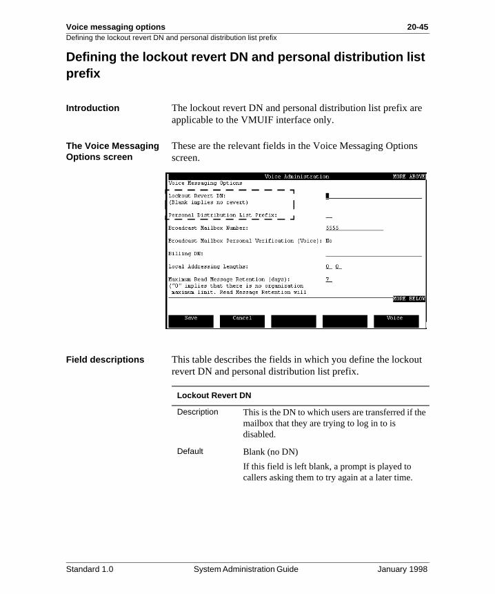
Introduction The lockout revert DN and personal distribution list prefix areapplicable to the VMUIF interface only.
The Voice Messaging Options screen
These are the relevant fields in the Voice Messaging Optionscreen.
Field descriptions This table describes the fields in which you define the lockourevert DN and personal distribution list prefix.
Lockout Revert DN
Description This is the DN to which users are transferred if thmailbox that they are trying to log in to is disabled.
Default Blank (no DN)
If this field is left blank, a prompt is played to callers asking them to try again at a later time.
Standard 1.0 System Administration Guide January 1998
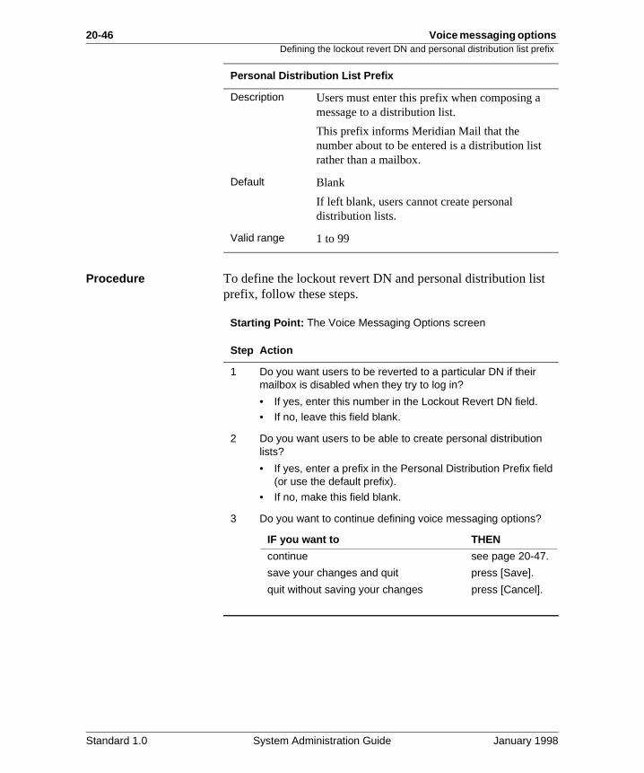
20-46 Voice messaging options Defining the lockout revert DN and personal distribution list prefix
Procedure To define the lockout revert DN and personal distribution listprefix, follow these steps.Starting Point: The Voice Messaging Options screen
Personal Distribution List Prefix
Description Users must enter this prefix when composing a message to a distribution list.
This prefix informs Meridian Mail that the number about to be entered is a distribution list rather than a mailbox.
Default Blank
If left blank, users cannot create personal distribution lists.
Valid range 1 to 99
Step Action
1 Do you want users to be reverted to a particular DN if their mailbox is disabled when they try to log in?
• If yes, enter this number in the Lockout Revert DN field.• If no, leave this field blank.
2 Do you want users to be able to create personal distribution lists?
• If yes, enter a prefix in the Personal Distribution Prefix field (or use the default prefix).
• If no, make this field blank.
3 Do you want to continue defining voice messaging options?
IF you want to THEN
continue see page 20-47.
save your changes and quit press [Save].
quit without saving your changes press [Cancel].
Standard 1.0 System Administration Guide January 1998
Voice messaging options 20-47Setting up the broadcast mailbox
e
tual
ular r to
.
and
, to
” on
Setting up the broadcast mailbox
Introduction Broadcast mailboxes can be set up for both the MMUI and VMUIF interface.
Description When you compose a message to the broadcast mailbox, thmessage is sent to all of the users on the system.
To set up a broadcast mailbox, all you have to do is assign amailbox number to the broadcast mailbox in the Voice Messaging Options screen. You do not need to set up an acmailbox through User Administration.
The Network Broadcast option
If Meridian Networking has been installed on your system, broadcast messages can also be sent to all users at a particremote site, to all users at each of a group of remote sites, oall users at all remote sites.
To enable network broadcast messaging, you must do the following:
• Fill in the required Network Broadcast Administration fields in the Network Configuration screen. See your Network Administration book for details.
• Record a personal verification for the broadcast mailbox
For details on Network broadcast messages, see “Recordingsending broadcast messages” on page 5-39.
The NMS broadcast message option
If NMS is installed on your system, broadcast messages canalso be sent to all users at a particular remote NMS locationall users at each of a group of locations, or to all users at all remote locations.
If your system also includes Meridian Mail Networking, this can include locations connected to remote sites.
For details, see “Recording and sending broadcast messagespage 5-39.
Standard 1.0 System Administration Guide January 1998
20-48 Voice messaging options Setting up the broadcast mailbox
in
The broadcast mailbox personal verification
You can record a personal verification for the broadcast mailbox so that when you enter the mailbox number during message composition, you get a verification that you have entered the correct number.
The personal verification for a broadcast mailbox can say something like this:
“Broadcast mailbox 5555.”
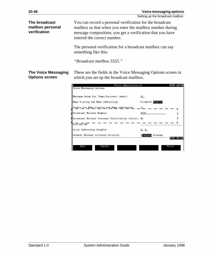
The Voice Messaging Options screen
These are the fields in the Voice Messaging Options screenwhich you set up the broadcast mailbox.
Standard 1.0 System Administration Guide January 1998
Voice messaging options 20-49Setting up the broadcast mailbox
ied
d
t
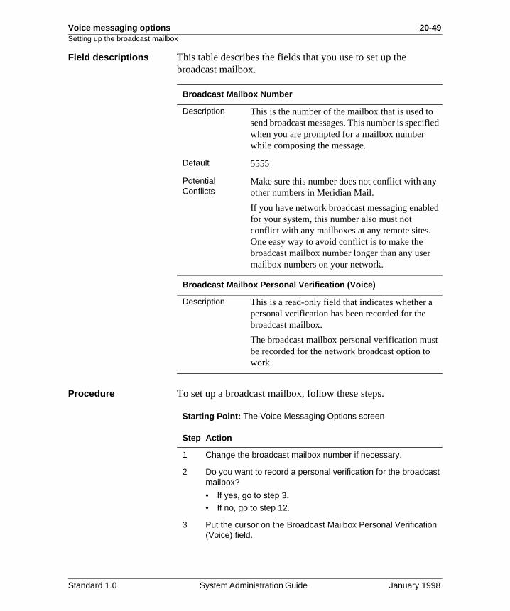
Field descriptions This table describes the fields that you use to set up the broadcast mailbox.
Procedure To set up a broadcast mailbox, follow these steps.
Starting Point: The Voice Messaging Options screen
Broadcast Mailbox Number
Description This is the number of the mailbox that is used tosend broadcast messages. This number is specifwhen you are prompted for a mailbox number while composing the message.
Default 5555
Potential Conflicts
Make sure this number does not conflict with anyother numbers in Meridian Mail.
If you have network broadcast messaging enablefor your system, this number also must not conflict with any mailboxes at any remote sites. One easy way to avoid conflict is to make the broadcast mailbox number longer than any user mailbox numbers on your network.
Broadcast Mailbox Personal Verification (Voice)
Description This is a read-only field that indicates whether a personal verification has been recorded for the broadcast mailbox.
The broadcast mailbox personal verification musbe recorded for the network broadcast option to work.
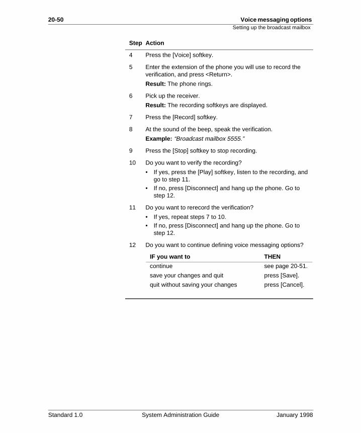
Step Action
1 Change the broadcast mailbox number if necessary.
2 Do you want to record a personal verification for the broadcast mailbox?
• If yes, go to step 3.
• If no, go to step 12.
3 Put the cursor on the Broadcast Mailbox Personal Verification (Voice) field.
Standard 1.0 System Administration Guide January 1998
20-50 Voice messaging options Setting up the broadcast mailbox
4 Press the [Voice] softkey.
5 Enter the extension of the phone you will use to record the verification, and press <Return>.
Result: The phone rings.
6 Pick up the receiver.
Result: The recording softkeys are displayed.
7 Press the [Record] softkey.
8 At the sound of the beep, speak the verification.
Example: “Broadcast mailbox 5555.”
9 Press the [Stop] softkey to stop recording.
10 Do you want to verify the recording?
• If yes, press the [Play] softkey, listen to the recording, and go to step 11.
• If no, press [Disconnect] and hang up the phone. Go to step 12.
11 Do you want to rerecord the verification?
• If yes, repeat steps 7 to 10.• If no, press [Disconnect] and hang up the phone. Go to
step 12.
12 Do you want to continue defining voice messaging options?
Step Action
IF you want to THEN
continue see page 20-51.
save your changes and quit press [Save].
quit without saving your changes press [Cancel].
Standard 1.0 System Administration Guide January 1998
Voice messaging options 20-51Defining the billing DN
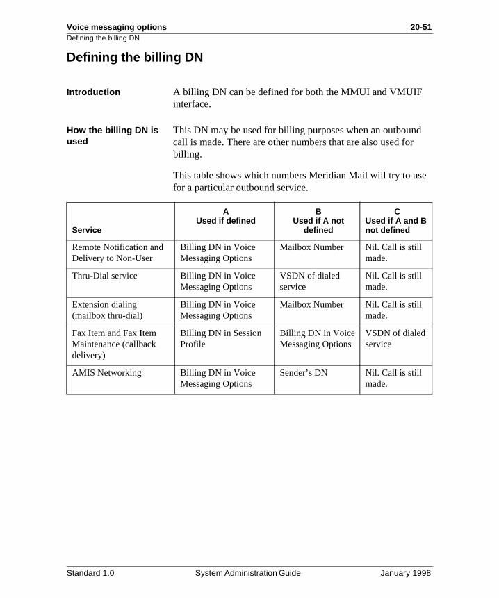
Defining the billing DN
Introduction A billing DN can be defined for both the MMUI and VMUIF interface.
How the billing DN is used
This DN may be used for billing purposes when an outboundcall is made. There are other numbers that are also used forbilling.
This table shows which numbers Meridian Mail will try to usefor a particular outbound service.
Service
AUsed if defined
BUsed if A not
defined
CUsed if A and B not defined
Remote Notification and Delivery to Non-User
Billing DN in Voice Messaging Options
Mailbox Number Nil. Call is still made.
Thru-Dial service Billing DN in Voice Messaging Options
VSDN of dialed service
Nil. Call is still made.
Extension dialing (mailbox thru-dial)
Billing DN in Voice Messaging Options
Mailbox Number Nil. Call is still made.
Fax Item and Fax Item Maintenance (callback delivery)
Billing DN in Session Profile
Billing DN in Voice Messaging Options
VSDN of dialed service
AMIS Networking Billing DN in Voice Messaging Options
Sender’s DN Nil. Call is still made.
Standard 1.0 System Administration Guide January 1998
20-52 Voice messaging options Defining the billing DN
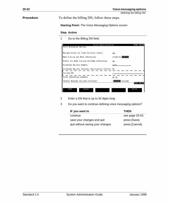
Procedure To define the billing DN, follow these steps.
Starting Point: The Voice Messaging Options screen
Step Action
1 Go to the Billing DN field.
2 Enter a DN that is up to 30 digits long.
3 Do you want to continue defining voice messaging options?
IF you want to THEN
continue see page 20-53.
save your changes and quit press [Save].
quit without saving your changes press [Cancel].
Standard 1.0 System Administration Guide January 1998
Voice messaging options 20-53Specifying the message delivery priority for networked systems
y
d
g
Specifying the message delivery priority for networked systems
When to use This procedure applies only to systems on which Meridian Networking is installed. Meridian Networking can be installedonly if the interface is MMUI.
Message delivery priority
The Default Message Delivery Priority field determines whennetwork messages are delivered. You can choose between Standard and Economy delivery. The default is Standard.
Standard delivery Messages are retained for a certain period of time before theare sent to remote sites.
This time period is defined in the Standard Holding Time fielin the Network Scheduling Parameters screen.
Economy delivery Messages are sent at a specific time each day, usually durinoff-hours, when rates are cheaper.
This delivery time is defined in the Economy Initiation Time field in the Network Scheduling Parameters screen.
Standard 1.0 System Administration Guide January 1998
20-54 Voice messaging options Specifying the message delivery priority for networked systems
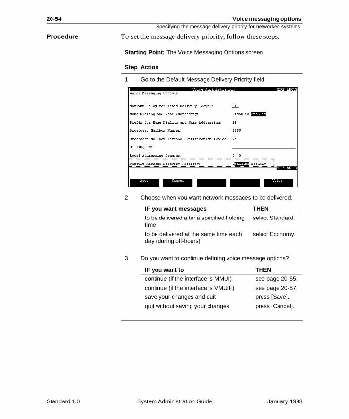
Procedure To set the message delivery priority, follow these steps.
Starting Point: The Voice Messaging Options screen
Step Action
1 Go to the Default Message Delivery Priority field.
2 Choose when you want network messages to be delivered.
3 Do you want to continue defining voice message options?
IF you want messages THEN
to be delivered after a specified holding time
select Standard.
to be delivered at the same time each day (during off-hours)
select Economy.
IF you want to THEN
continue (if the interface is MMUI) see page 20-55.
continue (if the interface is VMUIF) see page 20-57.
save your changes and quit press [Save].
quit without saving your changes press [Cancel].
Standard 1.0 System Administration Guide January 1998
Voice messaging options 20-55Specifying the mailbox full warning threshold
e .
rage of s
Specifying the mailbox full warning threshold
Introduction This warning threshold is applicable to the MMUI interface only.
Description When an MMUI user’s mailbox starts to get full, a warning message can be played to remind the user that his or her mailbox is almost full and to start deleting messages. This message can be disabled.
The warning threshold This threshold determines when this message is played. Thethreshold is based on how full the user’s mailbox is.
DefaultThe default setting is 85%.
Valid rangeYou can enter a value between 0 and 100%.
Example The warning threshold is set to 85%. The user’s voice storaglimit (as defined in the user’s class of service) is five minutes
A caller leaves a message that increases the user’s voice stoto 4 minutes 30 seconds. Since this is slightly more than 85%the total voice storage for the user, the next time the user logon, the mailbox full warning threshold message is played.
Standard 1.0 System Administration Guide January 1998
20-56 Voice messaging options Specifying the mailbox full warning threshold
.
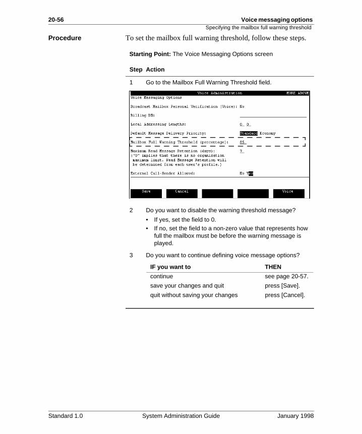
Procedure To set the mailbox full warning threshold, follow these stepsStarting Point: The Voice Messaging Options screen
Step Action
1 Go to the Mailbox Full Warning Threshold field.
2 Do you want to disable the warning threshold message?
• If yes, set the field to 0.• If no, set the field to a non-zero value that represents how
full the mailbox must be before the warning message is played.
3 Do you want to continue defining voice message options?
IF you want to THEN
continue see page 20-57.
save your changes and quit press [Save].
quit without saving your changes press [Cancel].
Standard 1.0 System Administration Guide January 1998

Voice messaging options 20-57Specifying the maximum read message retention
d on s a
. s to
nes
.
ld.
n
Specifying the maximum read message retention
Introduction The maximum read message retention applies to both the MMUI and VMUIF interfaces.
Description Once a user listens to a message, that message is still storethe system. A message that has been listened to is known aread message.
The system will begin to fill up with read messages over timeYou can either have Meridian Mail delete any read messageevery certain number of days, or you can leave it up to usersdelete read messages on their own.
Maximum read message retention
The Maximum Read Message Retention (days) field determihow long read messages are stored before being deleted.
DefaultThe default maximum read message retention is seven days
Valid rangeYou can enter a value between 0 and 31 (days).
WHEN this field THEN read messages are
is set to 0 not automatically deleted. They are retaineduntil deleted by the user.
is set to 1 or more deleted every X days as specified in this fie
ATTENTION
It is recommended that you set the read message retentioto a non-zero value to avoid filling up the disk with read messages.
Standard 1.0 System Administration Guide January 1998
20-58 Voice messaging options Specifying the maximum read message retention
nder
e
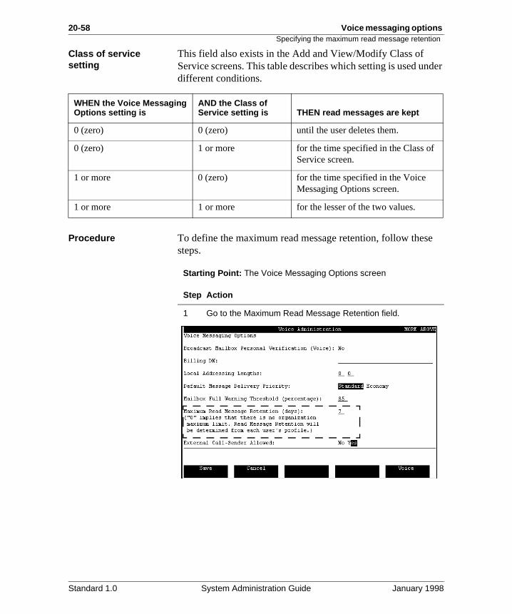
Class of service setting
This field also exists in the Add and View/Modify Class of Service screens. This table describes which setting is used udifferent conditions.
Procedure To define the maximum read message retention, follow thessteps.
Starting Point: The Voice Messaging Options screen
WHEN the Voice Messaging Options setting is
AND the Class of Service setting is THEN read messages are kept
0 (zero) 0 (zero) until the user deletes them.
0 (zero) 1 or more for the time specified in the Class ofService screen.
1 or more 0 (zero) for the time specified in the Voice Messaging Options screen.
1 or more 1 or more for the lesser of the two values.
Step Action
1 Go to the Maximum Read Message Retention field.
Standard 1.0 System Administration Guide January 1998
Voice messaging options 20-59Specifying the maximum read message retention
2 Do you want read messages to be stored until deleted by users?
• If yes, set the field to 0.• If no, set the field to a non-zero value that represents how
often you want read messages to be automatically deleted.
3 Do you want to continue defining voice message options?
Step Action
IF you want to THEN
continue see page 20-60.
save your changes and quit press [Save].
quit without saving your changes press [Cancel].
Standard 1.0 System Administration Guide January 1998
20-60 Voice messaging options Enabling/disabling external call sender
the
call
e
k.
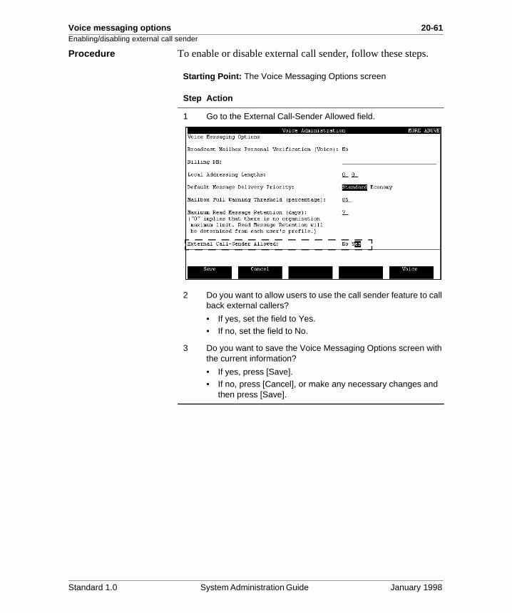
Enabling/disabling external call sender
Introduction External Call Sender is available in both the MMUI and VMUIF interfaces.
Description When a user is listening to a voice message left by another Meridian Mail user, the user can press 9 on the keypad to immediately call back the originator of the message. This is call sender feature.
The External Call Sender feature allows users to press 9 to back external callers who leave voice messages.
DefaultThis feature is enabled by default.
VMUIF interface For the VMUIF interface, this field interacts with the Call Sender field in the user’s class of service. Both fields must bset to Yes for External Call Sender to work.
Restricting External Call Sender
If you enable External Call Sender, apply the appropriate restrictions to the numbers that users are allowed to call bac
Restrictions are applied to external call sender in classes of service. See “The Add Class of Service screen (MMUI)” on page 26-13.
Standard 1.0 System Administration Guide January 1998
Voice messaging options 20-61Enabling/disabling external call sender
.
Procedure To enable or disable external call sender, follow these stepsStarting Point: The Voice Messaging Options screen
Step Action
1 Go to the External Call-Sender Allowed field.
2 Do you want to allow users to use the call sender feature to call back external callers?
• If yes, set the field to Yes.• If no, set the field to No.
3 Do you want to save the Voice Messaging Options screen with the current information?
• If yes, press [Save].• If no, press [Cancel], or make any necessary changes and
then press [Save].
Standard 1.0 System Administration Guide January 1998
20-62 Voice messaging options Enabling and configuring speed control
ou
al,
e the evel.
ther
back
ores
Enabling and configuring speed control
Introduction This feature is available to MMUI users only.
Description The speed control feature lets mailbox users control the playback speed of a voice mail message. As Administrator, ycan specify up to three speed increases for a user to apply during message playback (for example, 25% faster than norm50% faster, and 100% faster.)
User perspective During message playback, the user can press 2-3 to increasplayback speed by one level, and 2-1 to decrease it by one l
A 1.5-second time-out applies; the user must press 2, then ei1 or 3 immediately afterwards to use this feature. After 1.5 seconds, the 1 and 3 keys resume their usual message playroles (skipping the message back/forwards by 5 seconds.)
When a user reaches the highest speed level, the system ignany further speed increase commands.
This feature can be applied to the following:
• new messages
• previously read messages
• composed messages
• sent messages
• unsent messages
• deleted messages
Meridian Mail prompts, system-generated messages, and personal greetings and personal verifications will not be affected by this feature.
Standard 1.0 System Administration Guide January 1998
Voice messaging options 20-63Enabling and configuring speed control
Procedure To enable/configure the speed control feature, follow these steps.
Starting Point: The Voice Messaging Options screen
Step Action
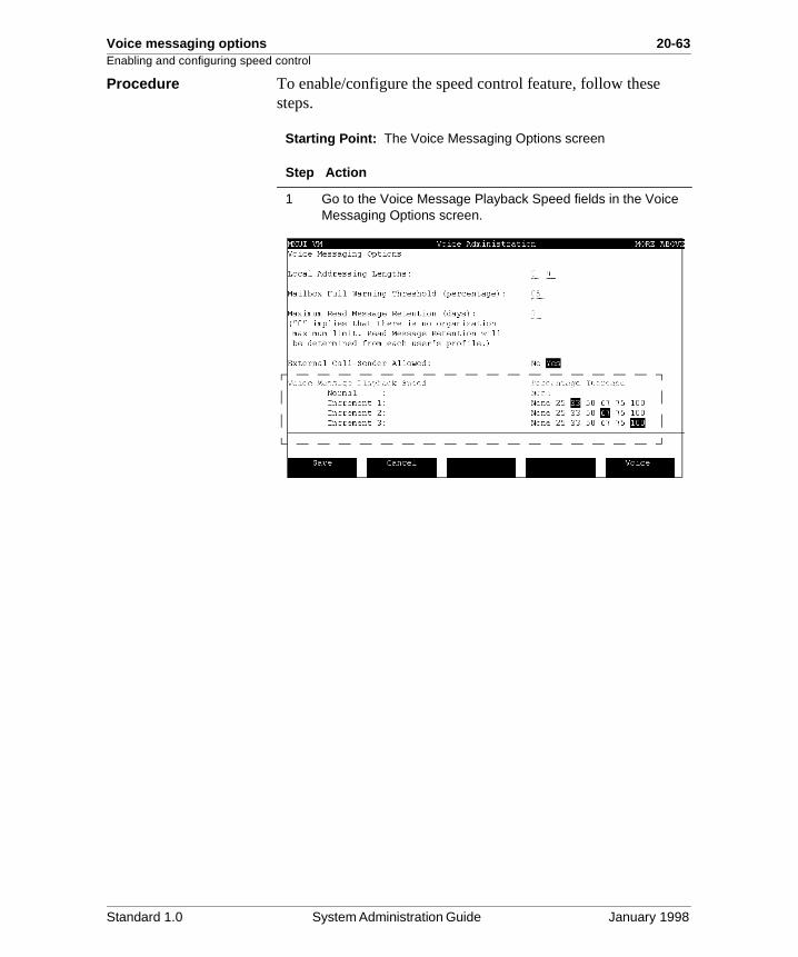
1 Go to the Voice Message Playback Speed fields in the Voice Messaging Options screen.
Standard 1.0 System Administration Guide January 1998
20-64 Voice messaging options Enabling and configuring speed control
2 For each of the three increments, select the desired speed increase for that level (for example, Increment 1 at 50%, Increment 2 at 75%, and Increment 3 at 100%).
Note: If two Increments are set to the same speed, there will be no speed change when the user moves up or down from one to the other.
3 Do you want to save the Voice Messaging Options screen with the current information?
• If yes, press [Save].• If no, press [Cancel], or make any necessary changes and
then press [Save].
Step Action
IF you want THEN set
three levels of increased speed
each increment to a higher number than the one before it.
two levels of increased speed
Increment 3 at the same number as Increment 2.
one level of increased speed
Increments 2 and 3 at the same level as Increment 1.
Standard 1.0 System Administration Guide January 1998
Chapter 21
Display options
In this chapter
Overview 21-2
Different ways of sorting the VSDN table 21-3
Different ways of sorting the service definitions tables 21-5
Different ways of sorting the Choice of Services and Menu Actions list
21-7
Changing the display options 21-9
21-2 Display options Overview
nt
he
Overview
Introduction This chapter describes the different ways information can bedisplayed on the Voice Services Administration screens. Youcan control two basic options:
• how information is sorted (for example, sort VSDN tableby DN or by Comment)
• whether or not the Choice of Services and Menu Actionslists are displayed
This chapter presents screen examples that show the differeways the Voice Services Administration screens appear according to the options you select. The section “Changing tdisplay options” on page 21-9 explains how to change the display options.
Standard 1.0 System Administration Guide January 1998
Display options 21-3Different ways of sorting the VSDN table
n
Different ways of sorting the VSDN table
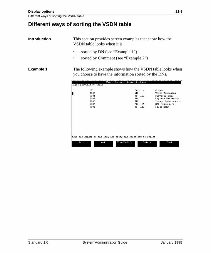
Introduction This section provides screen examples that show how the VSDN table looks when it is
• sorted by DN (see “Example 1”)
• sorted by Comment (see “Example 2”)
Example 1 The following example shows how the VSDN table looks wheyou choose to have the information sorted by the DNs.
Standard 1.0 System Administration Guide January 1998
21-4 Display options Different ways of sorting the VSDN table
n
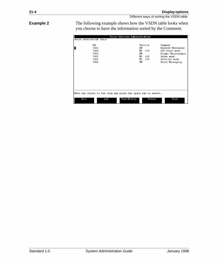
Example 2 The following example shows how the VSDN table looks wheyou choose to have the information sorted by the Comment.Standard 1.0 System Administration Guide January 1998
Display options 21-5Different ways of sorting the service definitions tables
s by
Different ways of sorting the service definitions tables
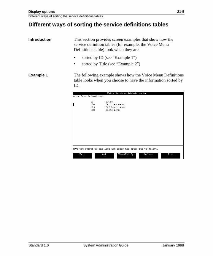
Introduction This section provides screen examples that show how the service definition tables (for example, the Voice Menu Definitions table) look when they are
• sorted by ID (see “Example 1”)
• sorted by Title (see “Example 2”)
Example 1 The following example shows how the Voice Menu Definitiontable looks when you choose to have the information sorted ID.
Standard 1.0 System Administration Guide January 1998
21-6 Display options Different ways of sorting the service definitions tables
s by
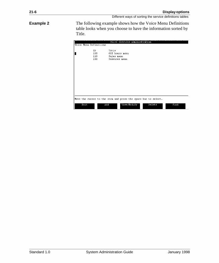
Example 2 The following example shows how the Voice Menu Definitiontable looks when you choose to have the information sorted Title.
Standard 1.0 System Administration Guide January 1998
Display options 21-7Different ways of sorting the Choice of Services and Menu Actions list
e
an
u .
Different ways of sorting the Choice of Services and Menu Actions list
Introduction This section provides screen examples that show how the Choice of Services list looks when it is
• sorted by acronym (see “Example 1”)
• sorted by description (see “Example 2”)
The effect on how the Menu Actions list appears would be thsame.
Definition: Menu Actions
“Menu Actions” refers to the default menu actions that you cchoose from when you define a voice menu. Refer to the Voice Services Application Guide for more details.
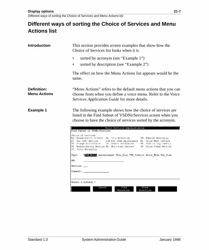
Example 1 The following example shows how the choice of services arelisted in the Find Subset of VSDNs/Services screen when yochoose to have the choice of services sorted by the acronym
Standard 1.0 System Administration Guide January 1998

21-8 Display options Different ways of sorting the Choice of Services and Menu Actions list
u ion.
Example 2 The following example shows how the choice of services arelisted in the Find Subset of VSDNs/Services screen when yochoose to have the choice of services sorted by the descript
Standard 1.0 System Administration Guide January 1998
Display options 21-9Changing the display options
s
ces ym
is
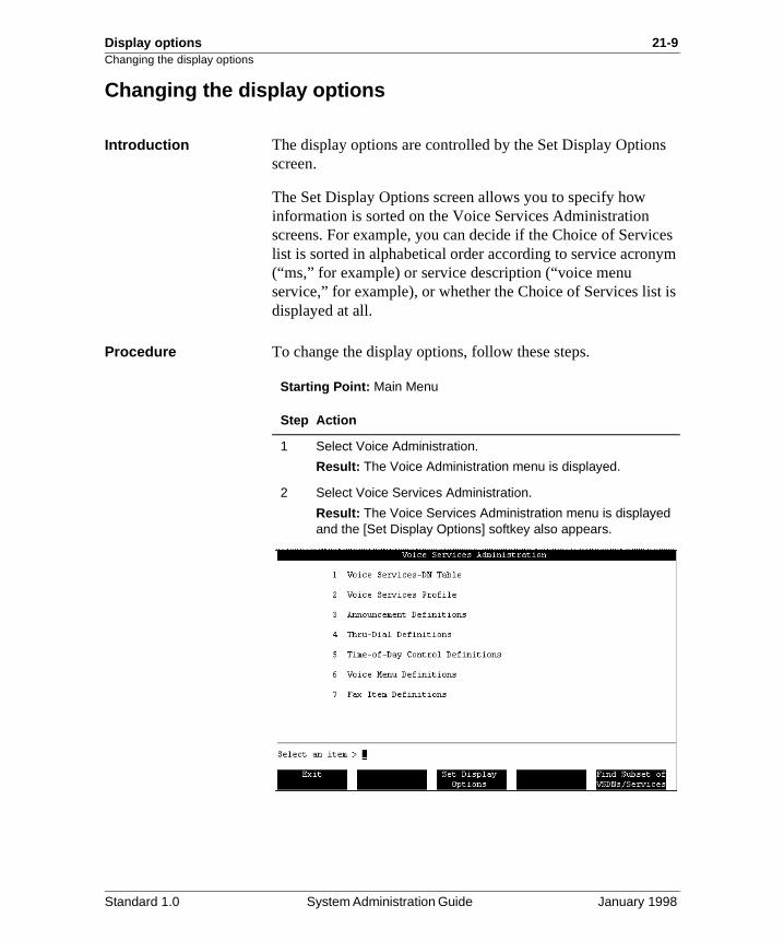
Changing the display options
Introduction The display options are controlled by the Set Display Optionscreen.
The Set Display Options screen allows you to specify how information is sorted on the Voice Services Administration screens. For example, you can decide if the Choice of Servilist is sorted in alphabetical order according to service acron(“ms,” for example) or service description (“voice menu service,” for example), or whether the Choice of Services listdisplayed at all.
Procedure To change the display options, follow these steps.
Starting Point: Main Menu
Step Action
1 Select Voice Administration.
Result: The Voice Administration menu is displayed.
2 Select Voice Services Administration.
Result: The Voice Services Administration menu is displayed and the [Set Display Options] softkey also appears.
Standard 1.0 System Administration Guide January 1998
21-10 Display options Changing the display options
s
Field descriptions The following fields and options appear on the Set Display Options screen.
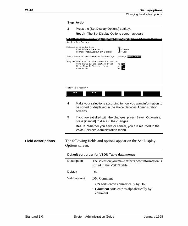
3 Press the [Set Display Options] softkey.
Result: The Set Display Options screen appears.
4 Make your selections according to how you want information to be sorted or displayed in the Voice Services Administration screens.
5 If you are satisfied with the changes, press [Save]. Otherwise, press [Cancel] to discard the changes.
Result: Whether you save or cancel, you are returned to the Voice Services Administration menu.
Step Action
Default sort order for VSDN Table data menus
Description The selection you make affects how information isorted in the VSDN table.
Default DN
Valid options DN, Comment
• DN sorts entries numerically by DN.
• Comment sorts entries alphabetically by comment.
Standard 1.0 System Administration Guide January 1998
Display options 21-11Changing the display options
s
f .
s
.
Default sort order for Service Definition data menus
Description The selection you make affects how information isorted in the service definitions tables (for example, in the Voice Menu Definitions screen).
Default ID
Valid options ID, Title
• ID sorts entries numerically by service IDs.
• Title sorts entries alphabetically by title.
Sort Choice of Services/Menu Actions by
Description The selection you make affects how the Choice oServices list and the Menu Actions list are sorted
The Choice of Services list appears on many screens including the Find subset of VSDNs/Services screen.
The Menu Actions list is displayed in the Add, View/Modify, and Delete a Voice Menu Definition screens.
Default Description
Valid options Description, Acronym
• Description sorts entries alphabetically by description.
• Title sorts entries alphabetically by title.
Display Choice of Services/Menu Actions in
Description You can turn the display of the Choice of Serviceor Menu Actions list on or off for the following:
• VSDN Table DN Information screens (Add, View/Modify, Delete DN Information)
• Voice Menu Definition screens (Add, View/Modify, Delete a Voice Menu Definition)
• Find Subset of VSDNs/Services screen
Default Yes
Valid options Yes, No
• Yes shows the choice of services/menu actions
• No hides the choice of services/menu actions.
Standard 1.0 System Administration Guide January 1998

21-12 Display options Changing the display options
Standard 1.0 System Administration Guide January 1998
Chapter 22
Finding and printing VSDNs and service definitions
In this chapter
Overview 22-2
Wildcards 22-5
The Find Subset of VSDNs/Services screen 22-7
Finding and printing VSDNs 22-9
Finding and printing service definitions 22-11
22-2 Finding and printing VSDNs and service definitions Overview
Overview
Introduction Use the find feature if you want to modify, delete, print, or simply view any of the following:
• a specific VSDN
• a range of VSDNs
• all VSDNs for a certain kind of service (such as announcements, voice menus, or fax items)
• a specific service definition
• a range of service definitions that have similar titles
Location of Find softkeys
Find softkeys are located on the following screens.
• the VSDN table
• service definition selection menus (such as the Announcement Definitions screen)
• the Voice Services Administration menu
Standard 1.0 System Administration Guide January 1998
Finding and printing VSDNs and service definitions 22-3Overview
,
ce ind
s, ax
Using Find as a shortcut
When you are adding a voice or fax service to Meridian Mailyou must go back and forth between the VSDN table and theAdd a service definition screen (to add a VSDN for the serviand to create a definition for the service). You can use the Fsoftkey to quickly move back and forth between the VSDN table screen and the service definition screen, as follows.
Starting Point: Any voice services administration screen that has a [Find] or [Find Subset of VSDNs/Services] softkey
Service definitions Service definitions exist for announcements, thru-dial servicetime-of-day controllers, and voice menus, and fax items (if Fon Demand is installed on your system).
Step Action
1 Press the [Find] softkey.
2 Select the service type that you want to add in the “Type” field and press <Tab>.
3 Press the [Find Selection] softkey.
Result: The service definition screen is displayed.
4 To return to the VSDN table, press the [Find] softkey, select VSDN_Entry in the Type field and press <Tab>. Then press the [Find Selection] softkey.
Standard 1.0 System Administration Guide January 1998
22-4 Finding and printing VSDNs and service definitions Overview
u
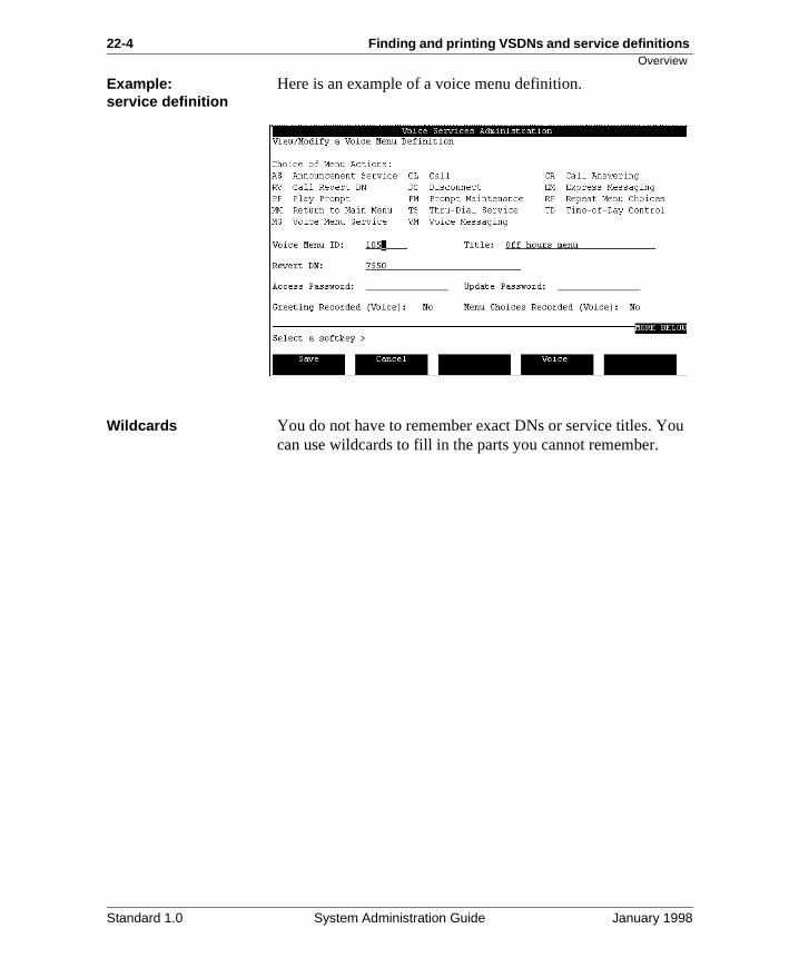
Example: service definition
Here is an example of a voice menu definition.
Wildcards You do not have to remember exact DNs or service titles. Yocan use wildcards to fill in the parts you cannot remember.
Standard 1.0 System Administration Guide January 1998
Finding and printing VSDNs and service definitions 22-5Wildcards
s
Wildcards
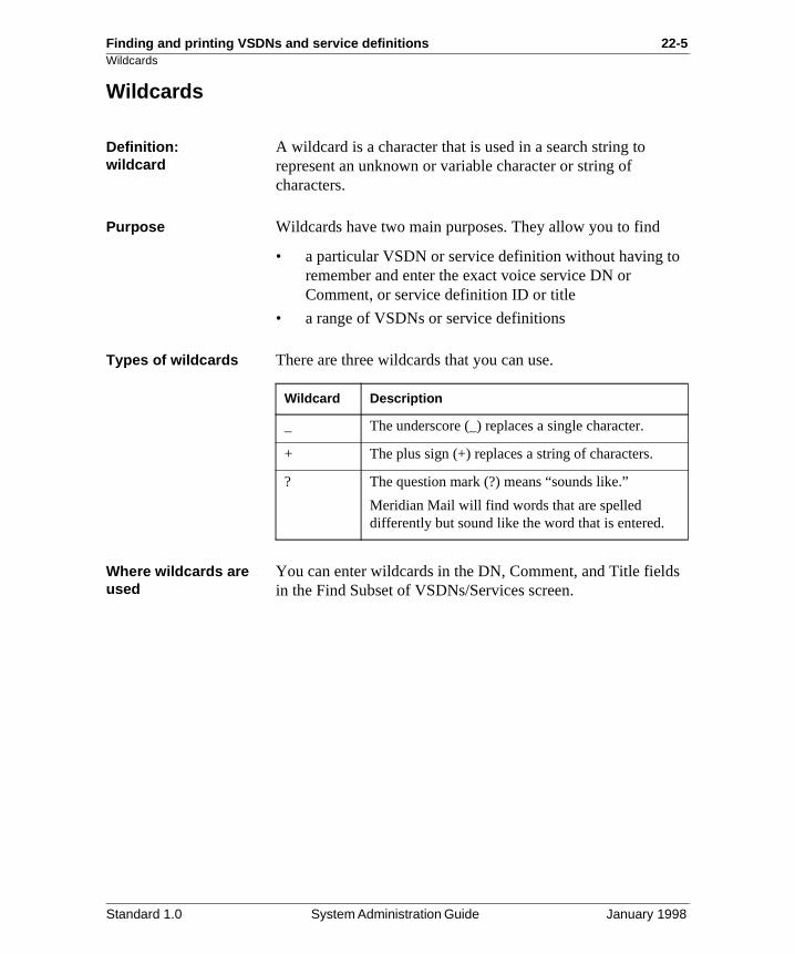
Definition: wildcard
A wildcard is a character that is used in a search string to represent an unknown or variable character or string of characters.
Purpose Wildcards have two main purposes. They allow you to find
• a particular VSDN or service definition without having toremember and enter the exact voice service DN or Comment, or service definition ID or title
• a range of VSDNs or service definitions
Types of wildcards There are three wildcards that you can use.
Where wildcards are used
You can enter wildcards in the DN, Comment, and Title fieldin the Find Subset of VSDNs/Services screen.
Wildcard Description
_ The underscore (_) replaces a single character.
+ The plus sign (+) replaces a string of characters.
? The question mark (?) means “sounds like.”
Meridian Mail will find words that are spelled differently but sound like the word that is entered.
Standard 1.0 System Administration Guide January 1998
22-6 Finding and printing VSDNs and service definitions Wildcards
en ge
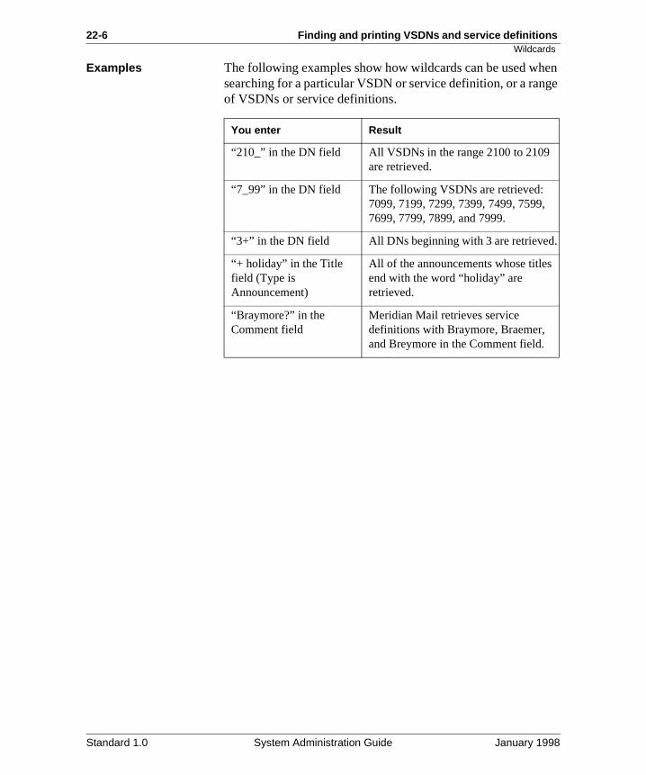
Examples The following examples show how wildcards can be used whsearching for a particular VSDN or service definition, or a ranof VSDNs or service definitions.
You enter Result
“210_” in the DN field All VSDNs in the range 2100 to 2109 are retrieved.
“7_99” in the DN field The following VSDNs are retrieved: 7099, 7199, 7299, 7399, 7499, 7599, 7699, 7799, 7899, and 7999.
“3+” in the DN field All DNs beginning with 3 are retrieved.
“+ holiday” in the Title field (Type is Announcement)
All of the announcements whose titles end with the word “holiday” are retrieved.
“Braymore?” in the Comment field
Meridian Mail retrieves service definitions with Braymore, Braemer, and Breymore in the Comment field.
Standard 1.0 System Administration Guide January 1998
Finding and printing VSDNs and service definitions 22-7The Find Subset of VSDNs/Services screen
ial,
The Find Subset of VSDNs/Services screen
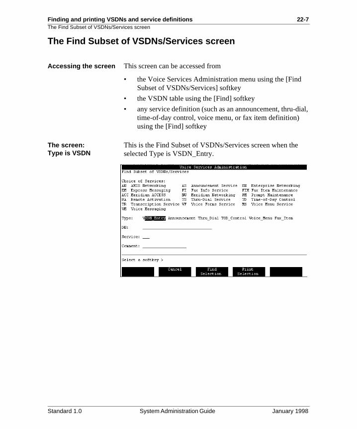
Accessing the screen This screen can be accessed from
• the Voice Services Administration menu using the [Find Subset of VSDNs/Services] softkey
• the VSDN table using the [Find] softkey
• any service definition (such as an announcement, thru-dtime-of-day control, voice menu, or fax item definition) using the [Find] softkey
The screen:Type is VSDN
This is the Find Subset of VSDNs/Services screen when theselected Type is VSDN_Entry.
Standard 1.0 System Administration Guide January 1998
22-8 Finding and printing VSDNs and service definitions The Find Subset of VSDNs/Services screen
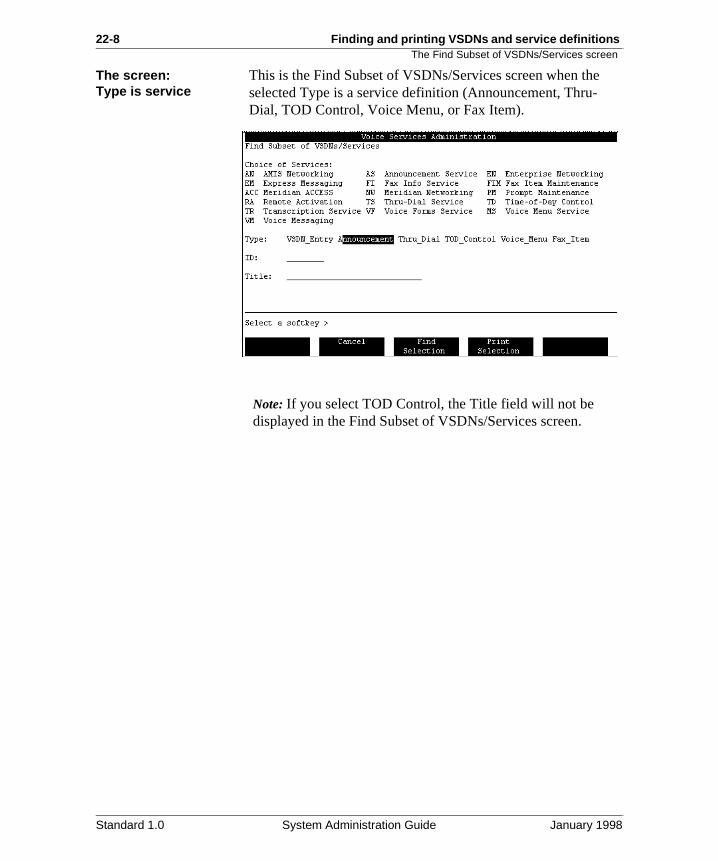
The screen: Type is serviceThis is the Find Subset of VSDNs/Services screen when theselected Type is a service definition (Announcement, Thru-Dial, TOD Control, Voice Menu, or Fax Item).
Note: If you select TOD Control, the Title field will not be displayed in the Find Subset of VSDNs/Services screen.
Standard 1.0 System Administration Guide January 1998
Finding and printing VSDNs and service definitions 22-9Finding and printing VSDNs
set
Finding and printing VSDNs
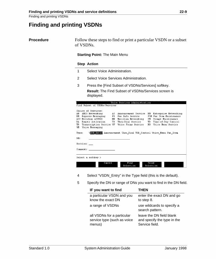
Procedure Follow these steps to find or print a particular VSDN or a subof VSDNs.
Starting Point: The Main Menu
Step Action
1 Select Voice Administration.
2 Select Voice Services Administration.
3 Press the [Find Subset of VSDNs/Services] softkey.
Result: The Find Subset of VSDNs/Services screen is displayed.
4 Select “VSDN_Entry” in the Type field (this is the default).
5 Specify the DN or range of DNs you want to find in the DN field.
IF you want to find THEN
a particular VSDN and you know the exact DN
enter the exact DN and go to step 8.
a range of VSDNs use wildcards to specify a search pattern.
all VSDNs for a particular service type (such as voice menus)
leave the DN field blank and specify the type in the Service field.
Standard 1.0 System Administration Guide January 1998
22-10 Finding and printing VSDNs and service definitions Finding and printing VSDNs
6 If you want to retrieve VSDNs of a certain service type only, specify one of the following types.
7 Enter a comment if this will help narrow the search.
Note 1: The comment must be exactly as entered in the service definition. If you do not know the exact comment, enter as much as you can and use wildcards for the rest.
Note 2: If the service is TD Time-of-Day Controller, then go to step 8.
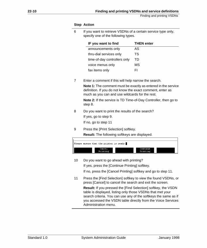
8 Do you want to print the results of the search?
If yes, go to step 9.
If no, go to step 11
9 Press the [Print Selection] softkey.
Result: The following softkeys are displayed.
10 Do you want to go ahead with printing?
If yes, press the [Continue Printing] softkey.
If no, press the [Cancel Printing] softkey and go to step 11.
11 Press the [Find Selection] softkey to view the found VSDNs, or press [Cancel] to cancel the search and exit the screen.
Result: If you pressed the [Find Selection] softkey, the VSDN table is displayed, listing only those VSDNs that met your search criteria. You can use any of the softkeys the same as if you accessed the VSDN table directly from the Voice Services Administration menu.
Step Action
IF you want to find THEN enter
announcements only AS
thru-dial services only TS
time-of-day controllers only TD
voice menus only MS
fax items only FI
Standard 1.0 System Administration Guide January 1998
Finding and printing VSDNs and service definitions 22-11Finding and printing service definitions
Finding and printing service definitions
Procedure To find or print a particular service definition or a subset of service definitions, follow these steps.
Starting Point: The Main Menu
Step Action
1 Select Voice Administration.
2 Select Voice Services Administration.
3 Press the [Find Subset of VSDNs/Services] softkey.
Result: The Find Subset of VSDNs/Services screen is displayed.
4 Select a service type in the Type field.
5 Specify the ID of the service definition you want to find.
6 Enter the exact service title, or part of the title and use wildcards for the rest.
7 Do you want to print the results of the search?
If yes, go to step 8.
If no, go to step 10.
8 Press the [Print Selection] softkey.
Result: The following softkeys are displayed.
IF you want to THEN
find a service and you know the exact ID
enter the exact ID and go to step 7.
find a service but you do not know the ID
leave the ID field blank and go to step 6 to fill in the Title field.
retrieve all service definitions of the specified type
leave the ID field and the Title field blank, and go to step 7.
Standard 1.0 System Administration Guide January 1998
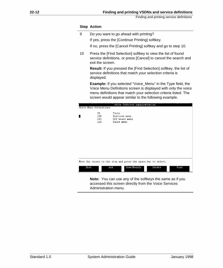
22-12 Finding and printing VSDNs and service definitions Finding and printing service definitions
9 Do you want to go ahead with printing?
If yes, press the [Continue Printing] softkey.
If no, press the [Cancel Printing] softkey and go to step 10.
10 Press the [Find Selection] softkey to view the list of found service definitions, or press [Cancel] to cancel the search and exit the screen.
Result: If you pressed the [Find Selection] softkey, the list of service definitions that match your selection criteria is displayed.
Example: If you selected “Voice_Menu” in the Type field, the Voice Menu Definitions screen is displayed with only the voice menu definitions that match your selection criteria listed. The screen would appear similar to the following example.
Note: You can use any of the softkeys the same as if you accessed this screen directly from the Voice Services Administration menu.
Step Action
Standard 1.0 System Administration Guide January 1998
Chapter 23
Configuring Meridian Mail services
In this chapter
Overview 23-2
Section A: Introduction 23-3
Section B: Planning your configuration 23-13
Section C: Configuring the Meridian 1 for Meridian Mail services
23-31
23-2 Configuring Meridian Mail services Overview
n
Overview
Configuring Meridian Mail services
Each dialable Meridian Mail service needs an ACD queueand a VSDN.
Setting up a Meridian Mail service, therefore, requires configuration on the Meridian 1 and in Meridian Mail.
Meridian 1 setupConfiguration of Meridian Mail services begins on the Meridian 1 where you must
• Set up one or more ACD queues for call handling.
• Set up a dummy queue for each Meridian Mail servicethat requires an access number.
Meridian Mail setupIn Meridian Mail, you must add the ACD queue DNs of thequeues you created on the Meridian 1 to the VSDN Table.This is where you indicate which service a particular DN should start up.
Meridian 1 setup This chapter describes how to set up the Meridian 1 to support Meridian Mail services.
Meridian Mail setup Chapter 24, “The VSDN table”, describes how to configurethe VSDN Table once you have added the necessary ACDqueues on the Meridian 1.
Section Description
Section A This is an introductory section that explains conceptsthat are necessary to understand how the Meridian 1must be set up to support Meridian Mail.
Section B This section discusses the different kinds of MeridiaMail ports, port requirements for services, and planning the Meridian 1 configuration.
Section C This section contains step-by-step procedures for configuring Meridian 1. This includes procedures for setting up ACD queues and dummy queues.
Standard 1.0 System Administration Guide January 1998
Configuring Meridian Mail services 23-3
Section A: Introduction
In this section
Automatic Call Distribution (ACD) 23-4
Meridian 1 – Meridian Mail connections 23-6
How Meridian Mail uses ACD 23-7
Types of queues 23-9
Assigning DNs to services in the VSDN table 23-11
Standard 1.0 System Administration Guide January 1998
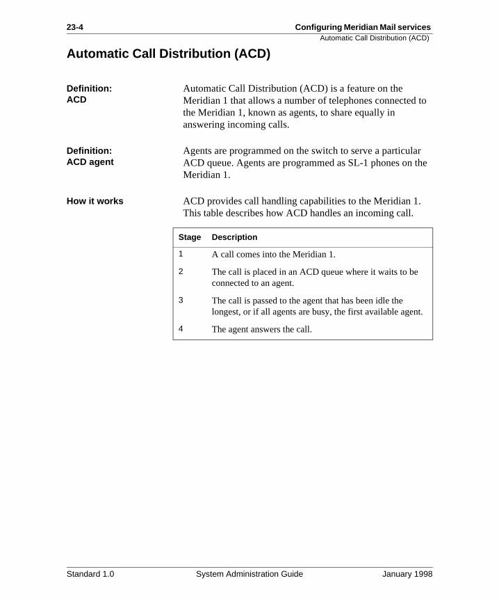
23-4 Configuring Meridian Mail services Automatic Call Distribution (ACD)
to
r the
.
Automatic Call Distribution (ACD)
Definition: ACD
Automatic Call Distribution (ACD) is a feature on the Meridian 1 that allows a number of telephones connected the Meridian 1, known as agents, to share equally in answering incoming calls.
Definition: ACD agent
Agents are programmed on the switch to serve a particulaACD queue. Agents are programmed as SL-1 phones on Meridian 1.
How it works ACD provides call handling capabilities to the Meridian 1. This table describes how ACD handles an incoming call.
Stage Description
1 A call comes into the Meridian 1.
2 The call is placed in an ACD queue where it waits to be connected to an agent.
3 The call is passed to the agent that has been idle the longest, or if all agents are busy, the first available agent
4 The agent answers the call.
Standard 1.0 System Administration Guide January 1998
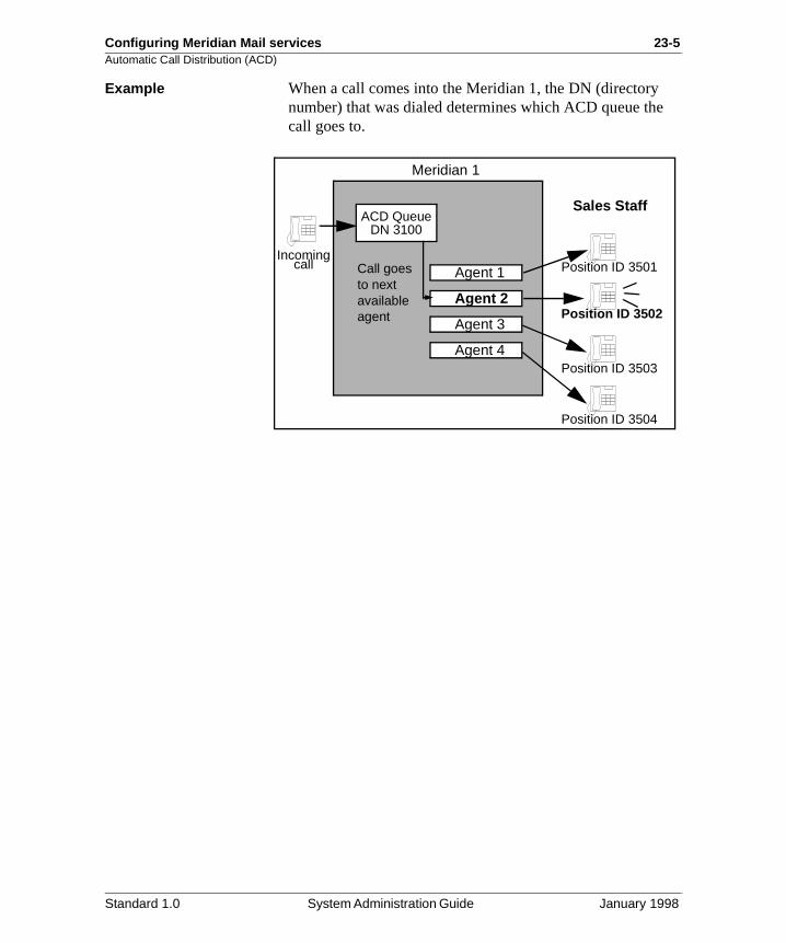
Configuring Meridian Mail services 23-5Automatic Call Distribution (ACD)
Example When a call comes into the Meridian 1, the DN (directorynumber) that was dialed determines which ACD queue thecall goes to.
Agent 1
Agent 2
Agent 3
Agent 4
Meridian 1
ACD QueueDN 3100
Call goes to next available agent
Incomingcall
Sales Staff
Position ID 3501
Position ID 3502
Position ID 3503
Position ID 3504
Standard 1.0 System Administration Guide January 1998
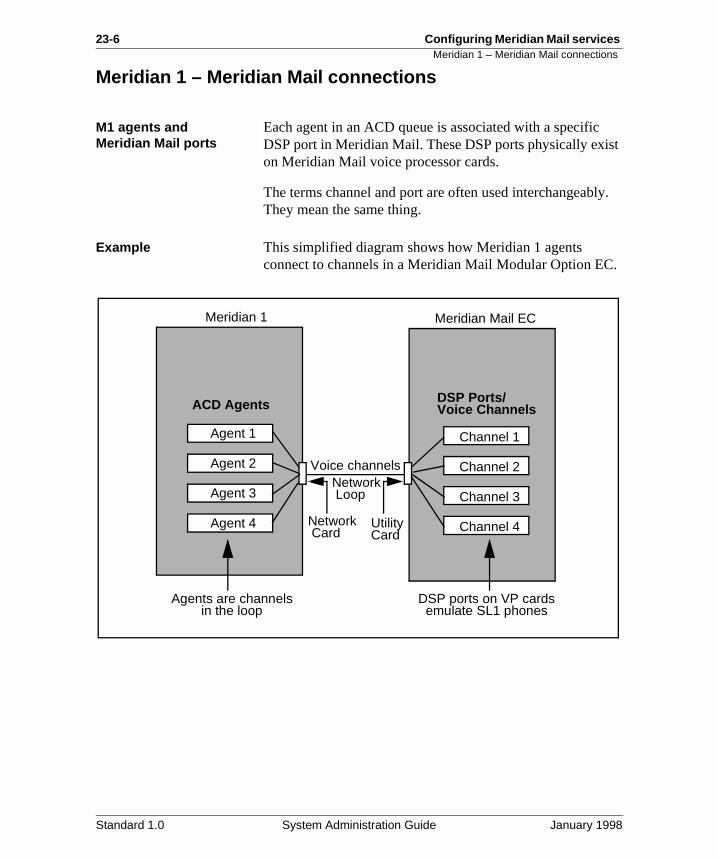
23-6 Configuring Meridian Mail services Meridian 1 – Meridian Mail connections
st
ly.
.
Meridian 1 – Meridian Mail connections
M1 agents and Meridian Mail ports
Each agent in an ACD queue is associated with a specificDSP port in Meridian Mail. These DSP ports physically exion Meridian Mail voice processor cards.
The terms channel and port are often used interchangeabThey mean the same thing.
Example This simplified diagram shows how Meridian 1 agents connect to channels in a Meridian Mail Modular Option EC
Agent 1
Agent 2
Agent 3
Agent 4
Channel 1
Channel 2
Channel 3
Channel 4
Meridian 1 Meridian Mail EC
ACD Agents DSP Ports/Voice Channels
Network Card
UtilityCard
Voice channelsNetwork Loop
Agents are channelsin the loop
DSP ports on VP cardsemulate SL1 phones
Standard 1.0 System Administration Guide January 1998
Configuring Meridian Mail services 23-7How Meridian Mail uses ACD
nts
r a
How Meridian Mail uses ACD
Virtual agents In Meridian Mail, there are no “physical” agents or telephones. Instead, “virtual agents” are used. Virtual ageare the DSP ports that are configured in the Meridian Mailsoftware. These ports emulate SL-1 telephone sets.
Directing calls to services
Meridian Mail uses ACD to perform its call handling functions. However, instead of being directed to agents ortelephones, incoming calls are directed to Meridian Mail services such as Voice Messaging, Express Messaging, oVoice Menu via the virtual agents.
Standard 1.0 System Administration Guide January 1998
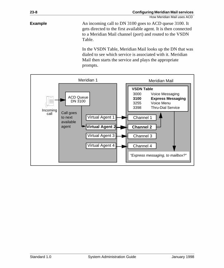
23-8 Configuring Meridian Mail services How Meridian Mail uses ACD
ed
s
Example An incoming call to DN 3100 goes to ACD queue 3100. It gets directed to the first available agent. It is then connectto a Meridian Mail channel (port) and routed to the VSDN Table.
In the VSDN Table, Meridian Mail looks up the DN that wadialed to see which service is associated with it. Meridian Mail then starts the service and plays the appropriate prompts.
Meridian 1
ACD QueueDN 3100
Call goes to next available agent
Incomingcall
Meridian Mail
Channel 1
Channel 2
Channel 3
Channel 4
VSDN Table3000 Voice Messaging3100 Express Messaging3255 Voice Menu3398 Thru-Dial Service
Virtual Agent 1
Virtual Agent 2
Virtual Agent 3
Virtual Agent 4
“Express messaging, to mailbox?”
Standard 1.0 System Administration Guide January 1998
Configuring Meridian Mail services 23-9Types of queues
he
ail
s or
d
d le
N, d
Types of queues
Two types of queues There are two types of queues that you can configure on tMeridian 1 for Meridian Mail:
• ACD agent queues
• dummy queues
Agent queues Agent queues contain agents and are served by Meridian Mports. These queues conduct the actual call handling.
The ACD DNs of agent queues are listed in the Meridian Mail Channel Allocation Table (CAT). The CAT indicates towhich queue a particular agent is assigned.
Other termsAgent queues are sometimes referred to as primary queuemain queues.
Dummy queues Dummy queues do not have agents. They accept calls anthen reroute callers to an agent queue for call handling. ANight Call Forward (NCFW) DN must be defined for all dummy queues. This DN determines the agent queue to which calls are rerouted.
Other termsDummy queues are sometimes referred to as secondary queues or service queues.
Why use dummy queues?
Many of the Meridian Mail services that you configure neeto be directly accessible. That is, you want callers to be abto dial a number in order to access the service.
Each directly dialable service needs a unique number, or Dso that when the DN is dialed, the correct service is starteand the appropriate prompts are played.
Standard 1.0 System Administration Guide January 1998
23-10 Configuring Meridian Mail services Types of queues
, ng, ce is
for
Why use dummy queues (cont’d)
Creating an agent queue for each service would be very inefficient, even if you had all the necessary ports. Insteadyou create a small number of agent queues for call handliand a dummy queue for each directly dialable service. Sineach dummy queue has an ACD DN associated with it, thDN becomes the access number for the service.
Example Two dummy queues have been set up. One (DN 6050) is Express Messaging. The other (DN 6122) is for a Voice Menu. They both forward to DN 6000.
Voice MessagingAgent Queue
DN 6000
Agent 2
Agent 1
Agent 3
Agent 4
Caller dials 6000 tolog into his mailbox
Caller dials 6050 to useExpress Messaging
Dummy QueueDN 6050
NCFW DNis 6000
Full-servicevoice ports
Dummy QueueDN 6122
NCFW DNis 6000
Forwarded
Forwarded
Caller dials 6122 toaccess a Voice Menu
Standard 1.0 System Administration Guide January 1998
Configuring Meridian Mail services 23-11Assigning DNs to services in the VSDN table
an
re e .
Assigning DNs to services in the VSDN table
Introduction When you create a dummy queue for a Meridian Mail service, the DN assigned to it is the access number for theservice.
Mapping DNs to services: the VSDN table
These ACD DNs are configured on the Meridian 1. When you create an ACD queue or dummy queue, you cannot specify the associated Meridian Mail service on the Meridi1. So how does Meridian Mail know which service to start when a particular DN is dialed?
The answer is the VSDN Table. All of the ACD DNs that aconfigured on the Meridian 1 for Meridian Mail services arentered into the VSDN Table. When you add a VSDN, youdefine the access DN (this is the ACD DN) and the serviceThis provides a mapping between ACD DNs and MeridianMail services.
Standard 1.0 System Administration Guide January 1998
23-12 Configuring Meridian Mail services Assigning DNs to services in the VSDN table
p
How DNs are looked upWhen a call comes into the system, Meridian Mail looks uthe dialed DN in the VSDN Table.
A caller dials a number.
The call is routed toMeridian Mail.
Meridian Mail checksthe VSDN table.
Is the dialed DN in theVSDN table?
YES NO
The service is started andthe caller hears theappropriate prompt.
Meridian Mail checks tosee if there is a mailbox
number match.
Is the dialed DN a validmailbox number?
YES NO
The caller is connectedto the mailbox.
The caller hears amessage and an errormessage is generated.
Standard 1.0 System Administration Guide January 1998
Configuring Meridian Mail services 23-13
Section B: Planning your configuration
In this section
Overview 23-14
Types of Meridian Mail ports 23-15
Port requirements for Meridian Mail services 23-18
Identifying the ports that are installed on your system 23-20
Should you dedicate ports? 23-23
Dedicating ports because of mixed port types 23-24
Dedicating ports to services 23-26
Determining how many ACD queues you need 23-28
Determining how many dummy queues you need 23-29
Standard 1.0 System Administration Guide January 1998
23-14 Configuring Meridian Mail services Overview
.
s
Overview
Introduction Before you begin configuring the Meridian 1 for Meridian Mail services, you need to do some analysis and planningYou will need to determine
• the types of Meridian Mail ports that are installed on your system
• the number of Meridian Mail services that require DNs
• whether you want to dedicate channels to any service
• how many ACD queues you need
• how many dummy queues you need
Standard 1.0 System Administration Guide January 1998
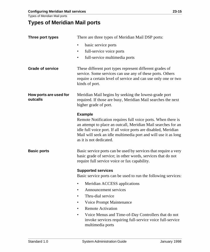
Configuring Meridian Mail services 23-15Types of Meridian Mail ports
wo
xt
s an
g
very t
es:
Types of Meridian Mail ports
Three port types There are three types of Meridian Mail DSP ports:
• basic service ports
• full-service voice ports
• full-service multimedia ports
Grade of service These different port types represent different grades of service. Some services can use any of these ports. Othersrequire a certain level of service and can use only one or tkinds of port.
How ports are used for outcalls
Meridian Mail begins by seeking the lowest-grade port required. If those are busy, Meridian Mail searches the nehigher grade of port.
ExampleRemote Notification requires full voice ports. When there ian attempt to place an outcall, Meridian Mail searches for idle full voice port. If all voice ports are disabled, Meridian Mail will seek an idle multimedia port and will use it as lonas it is not dedicated.
Basic ports Basic service ports can be used by services that require a basic grade of service; in other words, services that do norequire full service voice or fax capability.
Supported servicesBasic service ports can be used to run the following servic
• Meridian ACCESS applications
• Announcement services
• Thru-dial service
• Voice Prompt Maintenance
• Remote Activation
• Voice Menus and Time-of-Day Controllers that do notinvoke services requiring full-service voice full-servicemultimedia ports
Standard 1.0 System Administration Guide January 1998
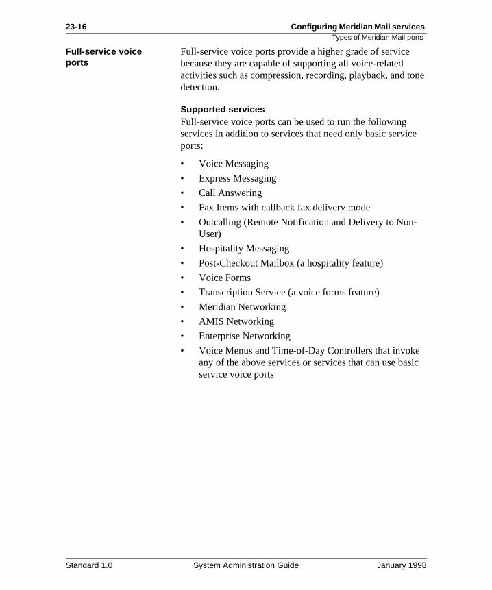
23-16 Configuring Meridian Mail services Types of Meridian Mail ports
one
e
sic
Full-service voice ports
Full-service voice ports provide a higher grade of service because they are capable of supporting all voice-related activities such as compression, recording, playback, and tdetection.
Supported servicesFull-service voice ports can be used to run the following services in addition to services that need only basic servicports:
• Voice Messaging
• Express Messaging
• Call Answering
• Fax Items with callback fax delivery mode
• Outcalling (Remote Notification and Delivery to Non-User)
• Hospitality Messaging
• Post-Checkout Mailbox (a hospitality feature)
• Voice Forms
• Transcription Service (a voice forms feature)
• Meridian Networking
• AMIS Networking
• Enterprise Networking
• Voice Menus and Time-of-Day Controllers that invokeany of the above services or services that can use baservice voice ports
Standard 1.0 System Administration Guide January 1998
Configuring Meridian Mail services 23-17Types of Meridian Mail ports
.
er
vice:
Full-service multimedia ports
A full-service multimedia port is not a different kind of portIt is the equivalent to approximately two full-service voice ports. A larger number of multimedia ports means a smallnumber of total ports on your system.
Supported servicesMultimedia ports are required by the following Fax on Demand services. They can also be used by any other ser
• Fax Items with same call or caller choice fax delivery mode
• Fax Item Maintenance
• Voice Menus and Time-of-Day Controllers that invokeany of the above services
Standard 1.0 System Administration Guide January 1998
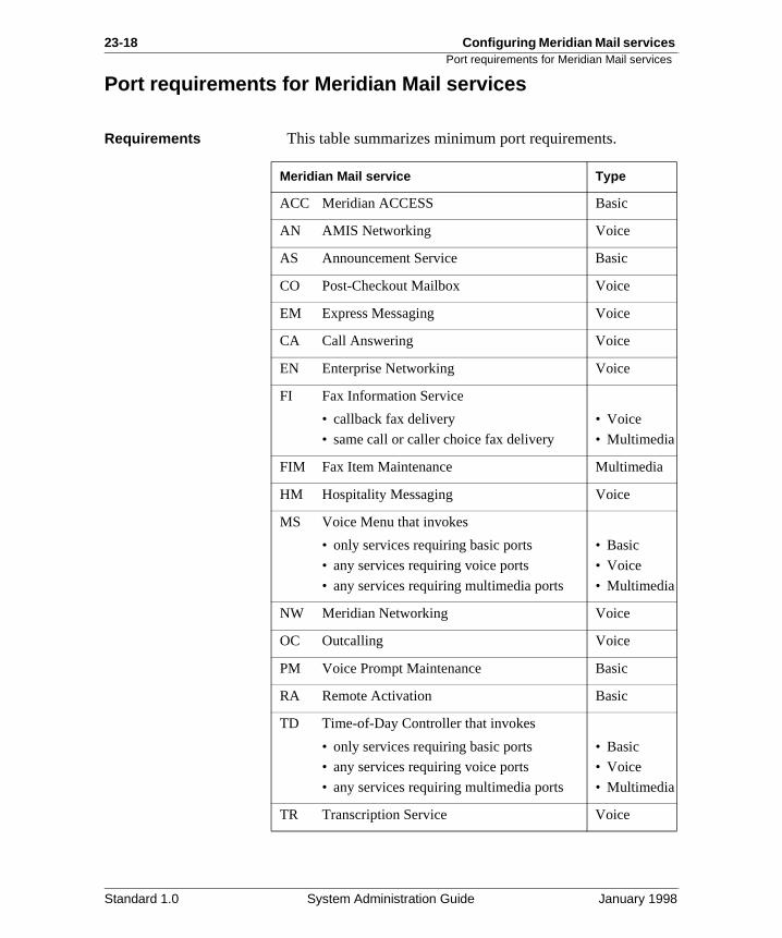
23-18 Configuring Meridian Mail services Port requirements for Meridian Mail services
Port requirements for Meridian Mail services
Requirements This table summarizes minimum port requirements.
Meridian Mail service Type
ACC Meridian ACCESS Basic
AN AMIS Networking Voice
AS Announcement Service Basic
CO Post-Checkout Mailbox Voice
EM Express Messaging Voice
CA Call Answering Voice
EN Enterprise Networking Voice
FI Fax Information Service
• callback fax delivery
• same call or caller choice fax delivery
• Voice
• Multimedia
FIM Fax Item Maintenance Multimedia
HM Hospitality Messaging Voice
MS Voice Menu that invokes
• only services requiring basic ports
• any services requiring voice ports
• any services requiring multimedia ports
• Basic
• Voice
• Multimedia
NW Meridian Networking Voice
OC Outcalling Voice
PM Voice Prompt Maintenance Basic
RA Remote Activation Basic
TD Time-of-Day Controller that invokes
• only services requiring basic ports
• any services requiring voice ports
• any services requiring multimedia ports
• Basic
• Voice
• Multimedia
TR Transcription Service Voice
Standard 1.0 System Administration Guide January 1998
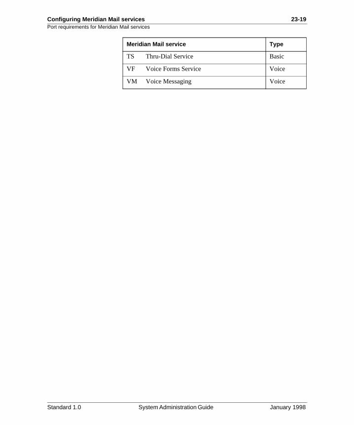
Configuring Meridian Mail services 23-19Port requirements for Meridian Mail services
TS Thru-Dial Service Basic
VF Voice Forms Service Voice
VM Voice Messaging Voice
Meridian Mail service Type
Standard 1.0 System Administration Guide January 1998
23-20 Configuring Meridian Mail services Identifying the ports that are installed on your system
ian
r e enu.
s
Identifying the ports that are installed on your system
Introduction You designate ports as one of the three types during MeridMail software installation or expansion.
You can check the types of ports that are installed on yousystem by viewing the Channel Allocation Table. This tablis accessible from the System Status and Maintenance m
Multimedia ports A multimedia port is actually made up of two voice ports. Each multimedia port, therefore, has two terminal number(TNs) associated with it.
Procedure To check the installed ports, follow these steps.
Starting Point: The Main Menu
Step Action
1 Select System Status and Maintenance.
2 Select Channel Allocation Table from the System Status and Maintenance menu.
• If you have a single node system, the Channel Allocation Table is displayed. Go to step 4.
• If you have a multinode system, go to step 3.
Standard 1.0 System Administration Guide January 1998
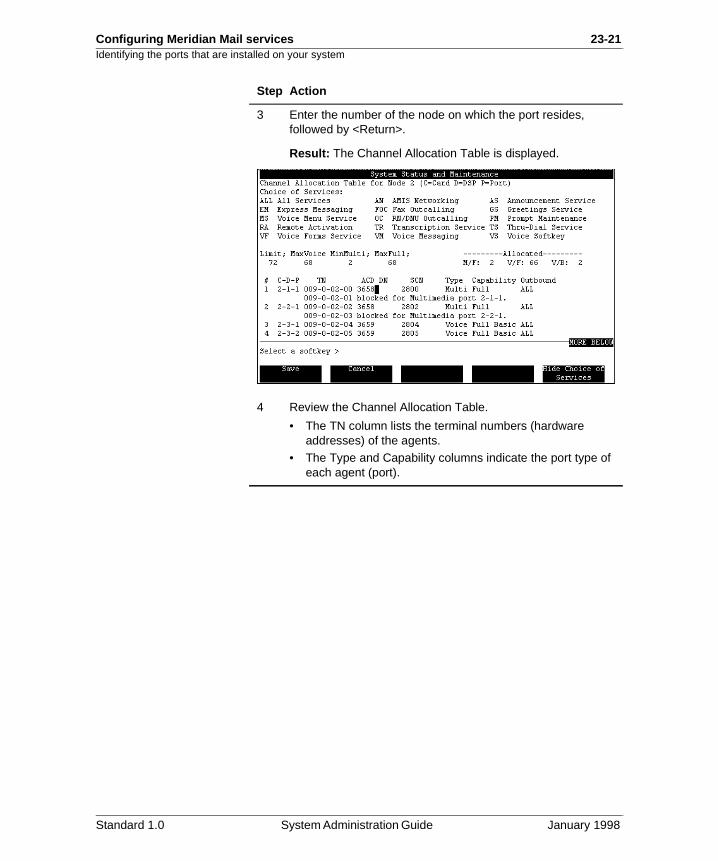
Configuring Meridian Mail services 23-21Identifying the ports that are installed on your system
3 Enter the number of the node on which the port resides, followed by <Return>.
Result: The Channel Allocation Table is displayed.
4 Review the Channel Allocation Table.
• The TN column lists the terminal numbers (hardware addresses) of the agents.
• The Type and Capability columns indicate the port type of each agent (port).
Step Action
Standard 1.0 System Administration Guide January 1998
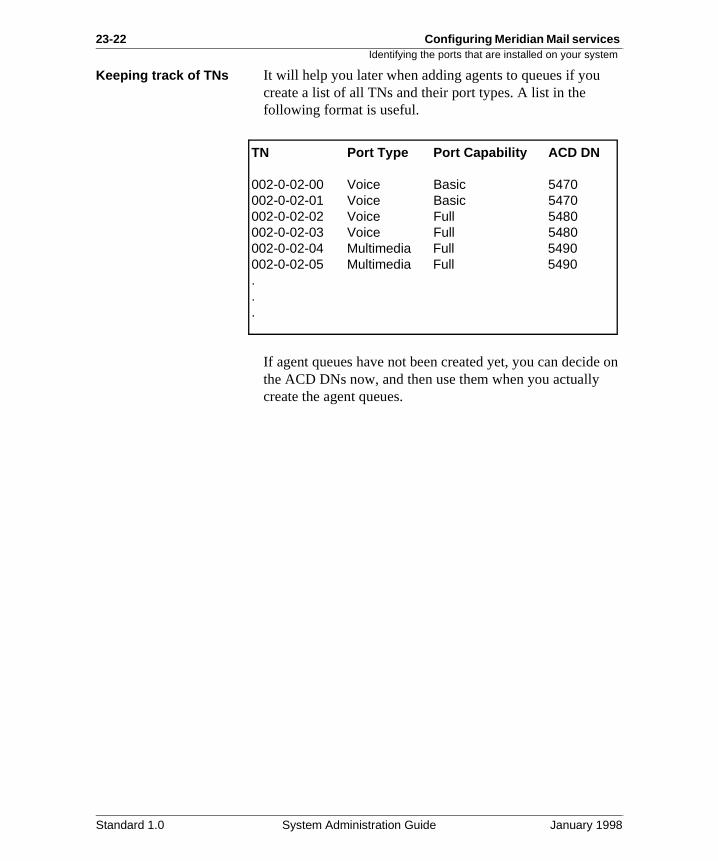
23-22 Configuring Meridian Mail services Identifying the ports that are installed on your system
e on
Keeping track of TNs It will help you later when adding agents to queues if you create a list of all TNs and their port types. A list in the following format is useful.
If agent queues have not been created yet, you can decidthe ACD DNs now, and then use them when you actually create the agent queues.
TN Port Type Port Capability ACD DN
002-0-02-00 Voice Basic 5470002-0-02-01 Voice Basic 5470002-0-02-02 Voice Full 5480002-0-02-03 Voice Full 5480002-0-02-04 Multimedia Full 5490002-0-02-05 Multimedia Full 5490...
Standard 1.0 System Administration Guide January 1998
Configuring Meridian Mail services 23-23Should you dedicate ports?
to
ts.
o st
is
n
Should you dedicate ports?
Introduction Agents (ports) can be shared by all services or dedicated particular services.
There are some conditions under which you must dedicateports, and others that are good reasons for dedicating por
Reasons for dedicating ports
There are two reasons for dedicating ports:
• If there is more than one port type on your system (twor more of basic, voice, and multimedia ports), you mucreate multiple ACD queues. A separate ACD queue required for each port type.
See “Dedicating ports because of mixed port types” opage 23-24.
• You want to dedicate ports to a particular service.
See “Dedicating ports to services” on page 23-26.
Standard 1.0 System Administration Guide January 1998
23-24 Configuring Meridian Mail services Dedicating ports because of mixed port types
rt.
ype
.
Dedicating ports because of mixed port types
Restriction An ACD queue can be serviced by only one type of DSP poFor example, the same ACD queue cannot be serviced byboth basic service DSP ports and full-service voice DSP ports.
Implication This means that you must create an ACD queue for each tof port. All agents that are added to it must correspond to Meridian Mail ports of the same type. This ensures that services access ports with an appropriate grade of service
Standard 1.0 System Administration Guide January 1998
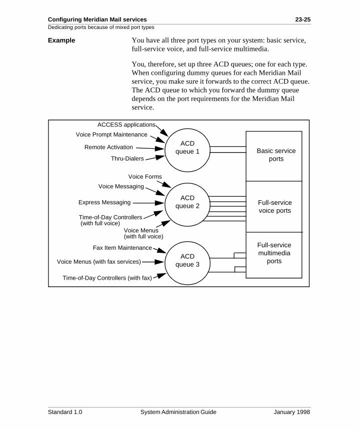
Configuring Meridian Mail services 23-25Dedicating ports because of mixed port types
e,
e.
ue.
Example You have all three port types on your system: basic servicfull-service voice, and full-service multimedia.
You, therefore, set up three ACD queues; one for each typWhen configuring dummy queues for each Meridian Mail service, you make sure it forwards to the correct ACD queThe ACD queue to which you forward the dummy queue depends on the port requirements for the Meridian Mail service.
ACD queue 1
ACD queue 2
ACD queue 3
ACCESS applications
Voice Prompt Maintenance
Remote Activation
Thru-Dialers
Voice Messaging
Express Messaging
Voice Forms
Time-of-Day Controllers
Voice Menus
Fax Item Maintenance
Voice Menus (with fax services)
Time-of-Day Controllers (with fax)
Basic service ports
Full-service voice ports
Full-service multimedia
ports
(with full voice)
(with full voice)
Standard 1.0 System Administration Guide January 1998
23-26 Configuring Meridian Mail services Dedicating ports to services
s
sed
of
orts
er
d ice
CD in
Dedicating ports to services
Reasons for dedicating ports
You may decide to dedicate ports to a particular Meridian Mail service for the following reasons:
• Traffic studies have indicated that a particular inboundservice is used heavily and that calls are being lost because the service is competing for ports with other services.
• It is crucial that a particular outbound service (such asRemote Notification or an ACCESS application) alwayhave access to ports.
Reasons not to dedicate ports
Share DSP ports as much as possible because they are umore efficiently when shared.
When ports are dedicated to services, the overall efficiencythe system is reduced for the following reasons:
• A port that is fully dedicated to a particular service cannot be used by any other service, even if idle.
• When ports are dedicated to a particular service, that service can use those ports only. It cannot use other pif the dedicated ports are in use.
Partially versus fully dedicated ports
When you dedicate ports to services, you are blocking othservices from using them. You can either partially or fully dedicate ports, although it is recommended that you fully dedicate them.
Blocking inbound calls
To block other services from using a channel when inbouncalls are made, you must create a ACD queue for the servand assign agents to it.
Blocking outbound calls
To block other services from using a channel for placing outbound calls only, you do not need to create a special Aqueue. All you have to do is dedicate the port to the servicethe Channel Allocation Table.
Standard 1.0 System Administration Guide January 1998
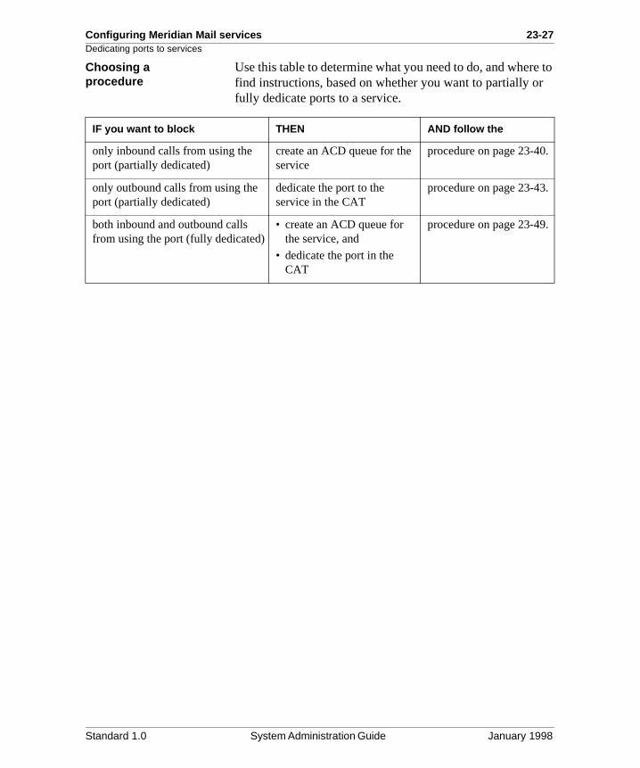
Configuring Meridian Mail services 23-27Dedicating ports to services
e to r
Choosing a procedure
Use this table to determine what you need to do, and wherfind instructions, based on whether you want to partially ofully dedicate ports to a service.
IF you want to block THEN AND follow the
only inbound calls from using the port (partially dedicated)
create an ACD queue for the service
procedure on page 23-40.
only outbound calls from using the port (partially dedicated)
dedicate the port to the service in the CAT
procedure on page 23-43.
both inbound and outbound calls from using the port (fully dedicated)
• create an ACD queue for the service, and
• dedicate the port in the CAT
procedure on page 23-49.
Standard 1.0 System Administration Guide January 1998
23-28 Configuring Meridian Mail services Determining how many ACD queues you need
y
se
Determining how many ACD queues you need
Introduction For more information about factors that influence how manACD queues you need, see the following:
• “Should you dedicate ports?” on page 23-23
• “Dedicating ports because of mixed port types” on page 23-24
• “Dedicating ports to services” on page 23-26
Procedure To determine how many ACD queues you need, follow thesteps.
Step Action
1 Do you know what kinds of ports you have installed on your system?
• If yes, go to step 2.
• If no, see “Identifying the ports that are installed on your system” on page 23-20 and then return to this procedure.
2 Do you have more than one port type on your system?
• If yes, you require one ACD queue per port type.• If no, you require only one ACD queue (for voice ports).
3 Do you want to fully dedicate ports to any services?
• If yes, you require one ACD queue for each service to which you want to dedicate ports for inbound and outbound calls.
• If no (you do not want to dedicate channels at all, or you only want to dedicate channels for outcalls), you do not need additional ACD queues.
4 Total the numbers that resulted from steps 2 to 3 to determine the total number of ACD queues that you need.
Standard 1.0 System Administration Guide January 1998
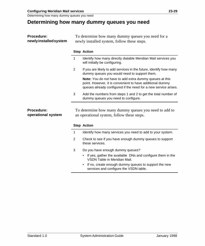
Configuring Meridian Mail services 23-29Determining how many dummy queues you need
to
Determining how many dummy queues you need
Procedure: newly installed system
To determine how many dummy queues you need for a newly installed system, follow these steps.
Procedure: operational system
To determine how many dummy queues you need to add an operational system, follow these steps.
Step Action
1 Identify how many directly dialable Meridian Mail services you will initially be configuring.
2 If you are likely to add services in the future, identify how many dummy queues you would need to support them.
Note: You do not have to add extra dummy queues at this point. However, it is convenient to have additional dummy queues already configured if the need for a new service arises.
3 Add the numbers from steps 1 and 2 to get the total number of dummy queues you need to configure.
Step Action
1 Identify how many services you need to add to your system.
2 Check to see if you have enough dummy queues to support these services.
3 Do you have enough dummy queues?
• If yes, gather the available DNs and configure them in the VSDN Table in Meridian Mail.
• If no, create enough dummy queues to support the new services and configure the VSDN table.
Standard 1.0 System Administration Guide January 1998

23-30 Configuring Meridian Mail services Determining how many dummy queues you need
Standard 1.0 System Administration Guide January 1998
Chapter 23
Configuring Meridian Mail services 23-31Section C: Configuring the Meridian 1 for Meridian Mail services
In this section
Overview 23-32
Creating ACD queues for a totally shared configuration 23-33
Creating ACD queues for a combination (shared and dedicated) configuration
23-35
Partially dedicating ports – blocking inbound calls only 23-40
Partially dedicating ports – blocking outbound calls only 23-43
Fully dedicating ports – blocking inbound and outbound calls 23-49
Creating an agent queue 23-52
Adding agents to a queue 23-55
Creating a dummy queue 23-59
Moving agents from one queue to another 23-61
Removing agents from a queue 23-63
Modifying the Channel Allocation Table after moving agents 23-64
Standard 1.0 System Administration Guide January 1998
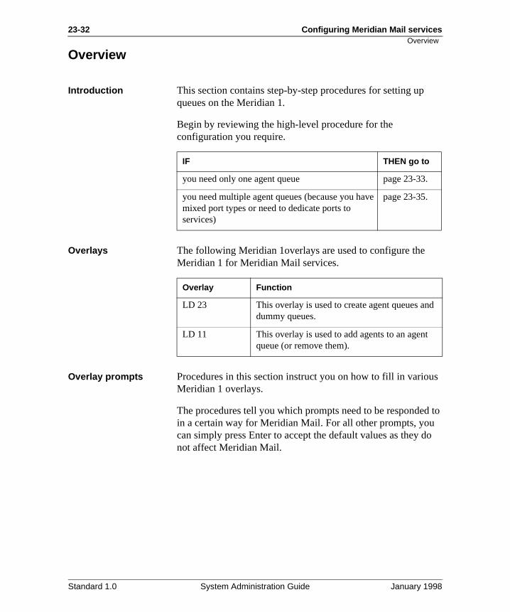
23-32 Configuring Meridian Mail services
s
d to o
d
Overview
Overview
Introduction This section contains step-by-step procedures for setting upqueues on the Meridian 1.
Begin by reviewing the high-level procedure for the configuration you require.
Overlays The following Meridian 1overlays are used to configure the Meridian 1 for Meridian Mail services.
Overlay prompts Procedures in this section instruct you on how to fill in variouMeridian 1 overlays.
The procedures tell you which prompts need to be respondein a certain way for Meridian Mail. For all other prompts, youcan simply press Enter to accept the default values as they dnot affect Meridian Mail.
IF THEN go to
you need only one agent queue page 23-33.
you need multiple agent queues (because you have mixed port types or need to dedicate ports to services)
page 23-35.
Overlay Function
LD 23 This overlay is used to create agent queues andummy queues.
LD 11 This overlay is used to add agents to an agent queue (or remove them).
Standard 1.0 System Administration Guide January 1998
Configuring Meridian Mail services 23-33Creating ACD queues for a totally shared configuration
ian
on”
g
, the r
Creating ACD queues for a totally shared configuration
Introduction All agents can be shared by all Meridian Mail services if
• you have only one type of Meridian Mail port (full-servicevoice ports only) and if
• you do not need to dedicate agents (ports) to any MeridMail services
If both of these conditions are not met, see “Creating ACD queues for a combination (shared and dedicated) configuration page 23-35.
The primary Voice Messaging queue
You can make the agent queue the primary Voice Messaginqueue. This means that you can publish the ACD DN of the agent queue as the Voice Messaging DN.
Alternatively, you can create a dummy queue for Voice Messaging that forwards to the agent queue. In this instanceDN of the agent queue is not published to users and is nevedirectly dialed.
Procedure This is a high-level procedure for configuring the Meridian 1 and Meridian Mail for services. Detailed step-by-step procedures are on the corresponding pages.
Step Action See
Meridian 1 configuration
1 Create an ACD agent queue. page 23-52
2 Add all agents to this queue. page 23-55
3 Create a dummy queue for each Meridian Mail service that needs to be directly dialable.
Note: Forward (NCFW) all dummy queues to the agent queue you created in step 1.
page 23-59
Meridian Mail configuration
4 Add the ACD DNs of the agent queue and dummy queues to the VSDN table.
Chapter 24
Standard 1.0 System Administration Guide January 1998
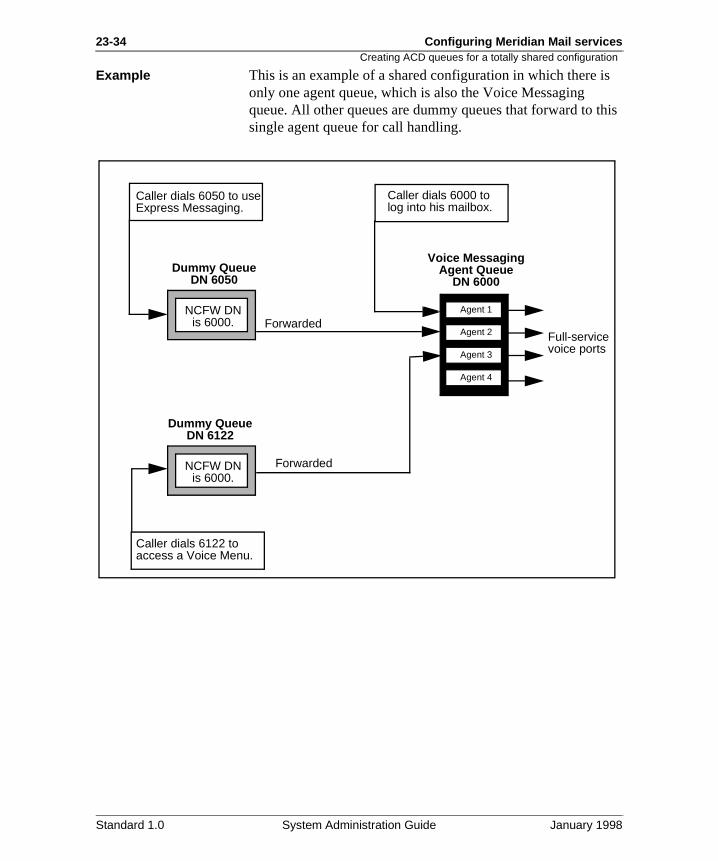
23-34 Configuring Meridian Mail services
s
his
Creating ACD queues for a totally shared configuration
Example This is an example of a shared configuration in which there ionly one agent queue, which is also the Voice Messaging queue. All other queues are dummy queues that forward to tsingle agent queue for call handling.
Voice MessagingAgent Queue
DN 6000
Agent 2
Agent 1
Agent 3
Agent 4
Caller dials 6000 tolog into his mailbox.
Caller dials 6050 to useExpress Messaging.
Dummy QueueDN 6050
NCFW DNis 6000.
Full-servicevoice ports
Dummy QueueDN 6122
NCFW DNis 6000.
Forwarded
Forwarded
Caller dials 6122 toaccess a Voice Menu.
Standard 1.0 System Administration Guide January 1998
Configuring Meridian Mail services 23-35Creating ACD queues for a combination (shared and dedicated) configuration
if
ne
l
, ver
all of
nd
te n .
il n
Creating ACD queues for a combination (shared and dedicated) configuration
Introduction You need a combination shared and dedicated configurationone or both of these conditions are met:
• There are mixed port types on your system (more than oof basic service, full-service voice, and full-service multimedia ports).
For more information, see “Dedicating ports because of mixed port types” on page 23-24.
• You need to dedicate ports to one or more Meridian Maiservices.
For more information, see “Dedicating ports to services”on page 23-26.
The primary Voice Messaging queue
You can make the agent queue that contains the full-servicevoice ports the primary Voice Messaging queue. This meansthat you can publish the ACD DN of this agent queue as theVoice Messaging DN.
Alternatively, you can create a dummy queue for Voice Messaging that forwards to this agent queue. In this instancethe DN of the agent queue is not published to users and is nedirectly dialed.
Do not mix port types in one queue
When adding agents to an agent queue, make sure they are the same type. An ACD agent queue cannot be serviced by Meridian Mail ports of different types (such as basic service afull-service voice ports).
Forwarding dummy queues
When you specify the NCFW (Night Call Forward) DN for a dummy queue, make sure you enter the DN of the appropriaagent queue. Ensure that the dummy queue terminates on aagent queue that is serviced by ports of the appropriate type
To identify the minimum port requirements for a Meridian Maservice, see “Port requirements for Meridian Mail services” opage 23-18.
Standard 1.0 System Administration Guide January 1998
23-36 Configuring Meridian Mail services
n a ep-
Creating ACD queues for a combination (shared and dedicated) configuration
Creating agent queues This is a high-level procedure for configuring agent queues icombination shared and dedicated configuration. Detailed stby-step procedures are on the corresponding pages.
Step Action See page
1 Create an ACD agent queue for full-service voice ports.
23-52
2 Add the necessary agents (that correspond to full-service voice ports in Meridian Mail) to this queue.
23-55
3 Do you have basic service ports on your system?
• If yes, go to step 4.
• If no, go to step 6.
4 Create an ACD agent queue for basic service ports.
23-52
5 Add the necessary agents (that correspond to basic service ports in Meridian Mail) to this queue.
23-55
6 Do you have full-service multimedia ports on your system?
• If yes, go to step 7.
• If no, go to step 9.
7 Create an ACD agent queue for full-service multimedia ports.
23-52
8 Add the necessary agents (that correspond to full-service multimedia ports in Meridian Mail) to this queue.
23-59
Standard 1.0 System Administration Guide January 1998
Configuring Meridian Mail services 23-37Creating ACD queues for a combination (shared and dedicated) configuration
.
Creating dummy queuesThis is a high-level procedure for configuring dummy queuesDetailed step-by-step procedures are on the corresponding pages.
9 Do you need to dedicate ports to any Meridian Mail services?
• If yes, go to step 10.• If no, go to step 11.
10 Choose the way in which you want to dedicate ports.
Note: When you are done, return to this procedure to define dummy queues andconfigure the VSDN table in Meridian Mail.
11 Go to the next procedure for creating dummy queues.
Step Action See page
IF you want to THEN go to
partially dedicate the ports by blocking only other inbound calls from using the ports
page 23-40.
partially dedicate the ports by blocking only other outbound calls from using the ports
page 23-43.
fully dedicate the ports by blocking all other inbound and outbound calls from using the ports (recommended method)
page 23-49.
Step Action See page
1 Identify the port requirements of each Meridian Mail service for which you need a dummy queue.
23-18
2 Create a dummy queue for each Meridian Mail service that needs to be directly dialable but that does not need dedicated ports.
Note: Make sure you forward each dummy queue to the correct agent queue.
23-59
3 Go to the next procedure for configuring Meridian Mail.
23-38
Standard 1.0 System Administration Guide January 1998
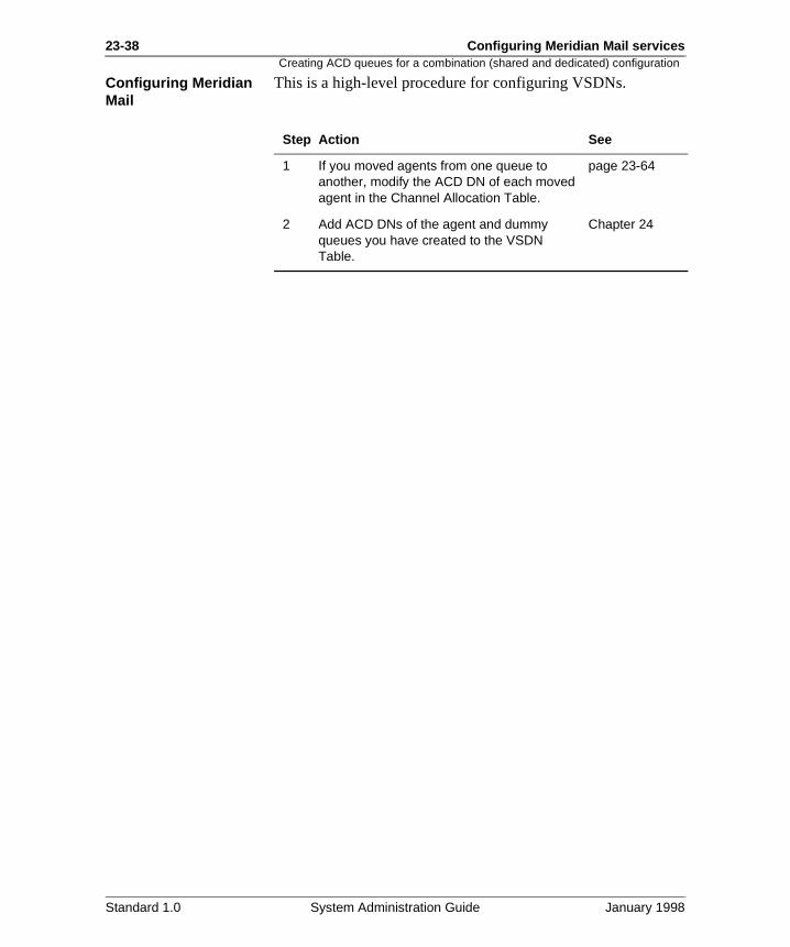
23-38 Configuring Meridian Mail services
Creating ACD queues for a combination (shared and dedicated) configurationConfiguring Meridian Mail
This is a high-level procedure for configuring VSDNs.
Step Action See
1 If you moved agents from one queue to another, modify the ACD DN of each moved agent in the Channel Allocation Table.
page 23-64
2 Add ACD DNs of the agent and dummy queues you have created to the VSDN Table.
Chapter 24
Standard 1.0 System Administration Guide January 1998
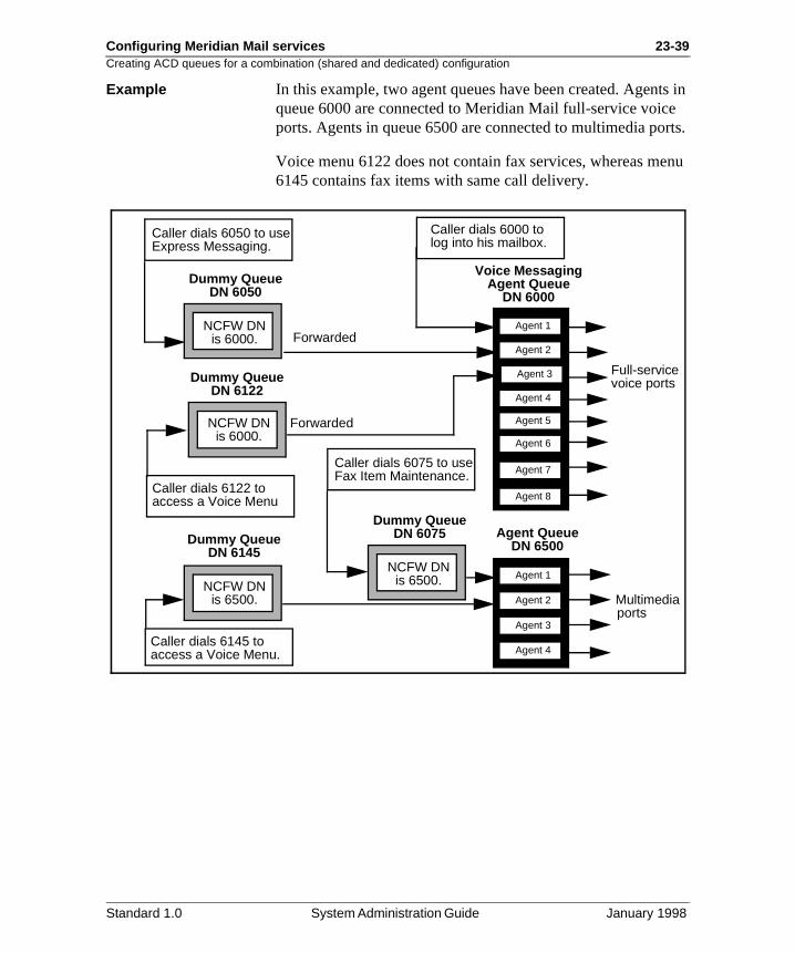
Configuring Meridian Mail services 23-39Creating ACD queues for a combination (shared and dedicated) configuration
ts in rts.
enu
Example In this example, two agent queues have been created. Agenqueue 6000 are connected to Meridian Mail full-service voiceports. Agents in queue 6500 are connected to multimedia po
Voice menu 6122 does not contain fax services, whereas m6145 contains fax items with same call delivery.
Voice MessagingAgent Queue
DN 6000
Agent 2
Agent 1
Agent 3
Agent 4
Caller dials 6000 tolog into his mailbox.
Caller dials 6050 to useExpress Messaging.
Dummy QueueDN 6050
NCFW DNis 6000.
Full-servicevoice portsDummy Queue
DN 6122
NCFW DNis 6000.
Forwarded
Forwarded
Caller dials 6122 toaccess a Voice Menu
Agent 5
Agent 6
Agent 2
Agent 1
Agent 3
Agent 4
Agent QueueDN 6500
Agent 7
Agent 8
Multimediaports
Dummy QueueDN 6145
NCFW DNis 6500.
Caller dials 6145 toaccess a Voice Menu.
Caller dials 6075 to useFax Item Maintenance.
Dummy QueueDN 6075
NCFW DNis 6500.
Standard 1.0 System Administration Guide January 1998
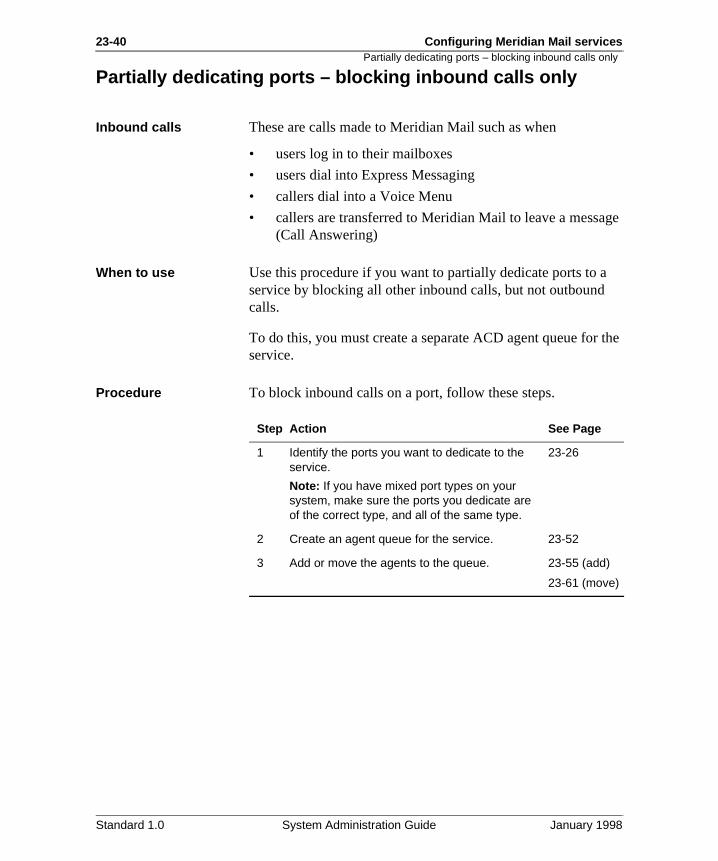
23-40 Configuring Meridian Mail services
ge
the
Partially dedicating ports – blocking inbound calls only
Partially dedicating ports – blocking inbound calls only
Inbound calls These are calls made to Meridian Mail such as when
• users log in to their mailboxes
• users dial into Express Messaging
• callers dial into a Voice Menu
• callers are transferred to Meridian Mail to leave a messa(Call Answering)
When to use Use this procedure if you want to partially dedicate ports to aservice by blocking all other inbound calls, but not outboundcalls.
To do this, you must create a separate ACD agent queue forservice.
Procedure To block inbound calls on a port, follow these steps.
Step Action See Page
1 Identify the ports you want to dedicate to the service.
Note: If you have mixed port types on your system, make sure the ports you dedicate are of the correct type, and all of the same type.
23-26
2 Create an agent queue for the service. 23-52
3 Add or move the agents to the queue. 23-55 (add)
23-61 (move)
Standard 1.0 System Administration Guide January 1998
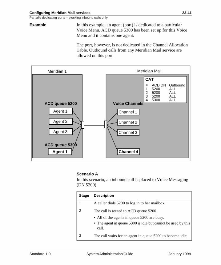
Configuring Meridian Mail services 23-41Partially dedicating ports – blocking inbound calls only
e
n
g
his
.
Example In this example, an agent (port) is dedicated to a particular Voice Menu. ACD queue 5300 has been set up for this VoicMenu and it contains one agent.
The port, however, is not dedicated in the Channel AllocatioTable. Outbound calls from any Meridian Mail service are allowed on this port.
Scenario AIn this scenario, an inbound call is placed to Voice Messagin(DN 5200).
Agent 1
Agent 2
Agent 3
Agent 1
Channel 1
Channel 2
Channel 3
Channel 4
Meridian 1 Meridian Mail
ACD queue 5200
ACD queue 5300
Voice Channels
CAT# ACD DN Outbound1 5200 ALL2 5200 ALL3 5200 ALL4 5300 ALL
Stage Description
1 A caller dials 5200 to log in to her mailbox.
2 The call is routed to ACD queue 5200.
• All of the agents in queue 5200 are busy.
• The agent in queue 5300 is idle but cannot be used by tcall.
3 The call waits for an agent in queue 5200 to become idle
Standard 1.0 System Administration Guide January 1998
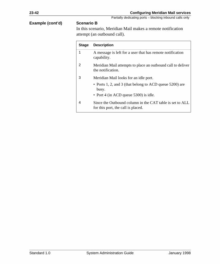
23-42 Configuring Meridian Mail services
r
L
Partially dedicating ports – blocking inbound calls only
Example (cont’d) Scenario BIn this scenario, Meridian Mail makes a remote notification attempt (an outbound call).
Stage Description
1 A message is left for a user that has remote notification capability.
2 Meridian Mail attempts to place an outbound call to delivethe notification.
3 Meridian Mail looks for an idle port.
• Ports 1, 2, and 3 (that belong to ACD queue 5200) arebusy.
• Port 4 (in ACD queue 5300) is idle.
4 Since the Outbound column in the CAT table is set to ALfor this port, the call is placed.
Standard 1.0 System Administration Guide January 1998
Configuring Meridian Mail services 23-43Partially dedicating ports – blocking outbound calls only
n
Partially dedicating ports – blocking outbound calls only
Outbound calls These are calls made by Meridian Mail. The following MeridiaMail features make outbound calls:
• all networking features
• Outcalling (Remote Notification and Delivery to Non-User)
• Fax on Demand (call back fax delivery)
When to use Use this procedure if you want to partially dedicate ports to aservice by blocking all other outbound calls but not inbound calls.
To do this, you must do the following:
• Disable the ports you want to dedicate.
• Modify the Outbound column in the Channel Allocation Table.
• Reenable the ports.
Standard 1.0 System Administration Guide January 1998
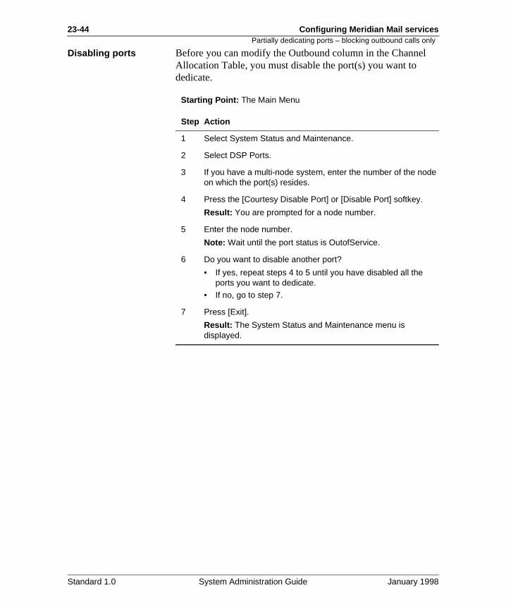
23-44 Configuring Meridian Mail services
Partially dedicating ports – blocking outbound calls onlyDisabling ports Before you can modify the Outbound column in the ChannelAllocation Table, you must disable the port(s) you want to dedicate.
Starting Point: The Main Menu
Step Action
1 Select System Status and Maintenance.
2 Select DSP Ports.
3 If you have a multi-node system, enter the number of the node on which the port(s) resides.
4 Press the [Courtesy Disable Port] or [Disable Port] softkey.
Result: You are prompted for a node number.
5 Enter the node number.
Note: Wait until the port status is OutofService.
6 Do you want to disable another port?
• If yes, repeat steps 4 to 5 until you have disabled all the ports you want to dedicate.
• If no, go to step 7.
7 Press [Exit].
Result: The System Status and Maintenance menu is displayed.
Standard 1.0 System Administration Guide January 1998
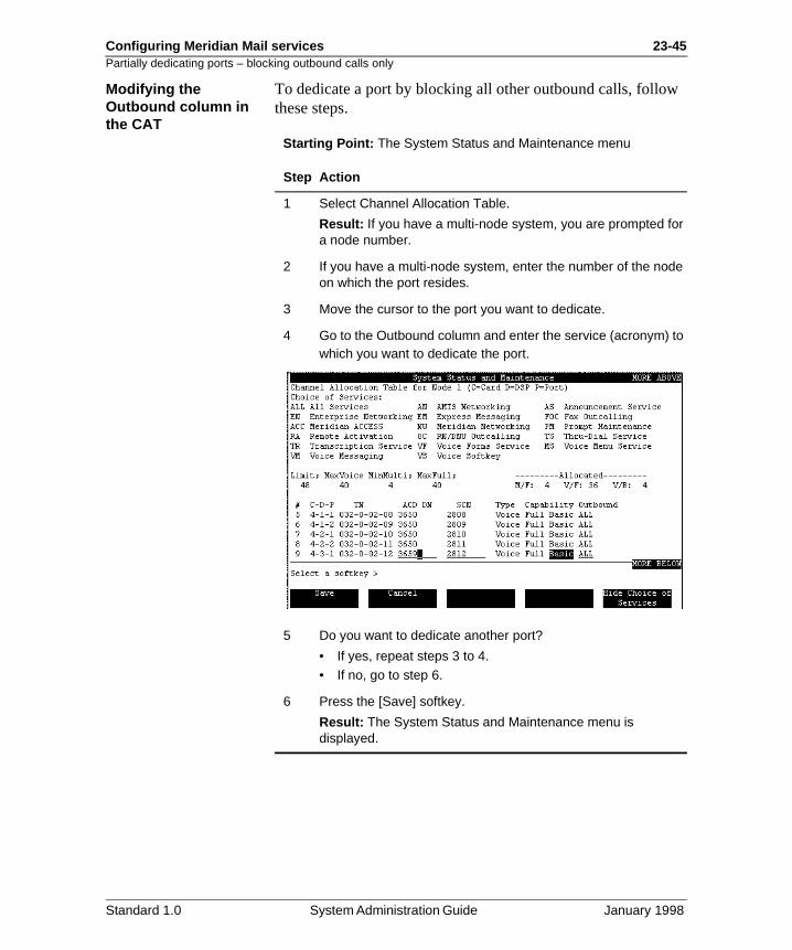
Configuring Meridian Mail services 23-45Partially dedicating ports – blocking outbound calls only
Modifying the Outbound column in the CATTo dedicate a port by blocking all other outbound calls, followthese steps.
Starting Point: The System Status and Maintenance menu
Step Action
1 Select Channel Allocation Table.
Result: If you have a multi-node system, you are prompted for a node number.
2 If you have a multi-node system, enter the number of the node on which the port resides.
3 Move the cursor to the port you want to dedicate.
4 Go to the Outbound column and enter the service (acronym) to which you want to dedicate the port.
5 Do you want to dedicate another port?
• If yes, repeat steps 3 to 4.• If no, go to step 6.
6 Press the [Save] softkey.
Result: The System Status and Maintenance menu is displayed.
Standard 1.0 System Administration Guide January 1998
23-46 Configuring Meridian Mail services
Partially dedicating ports – blocking outbound calls onlyReenabling the ports To reenable the ports you dedicated, follow these steps.
Starting Point: The System Status and Maintenance menu
Step Action
1 Select DSP Ports.
Result: If you have a multi-node system, you are prompted for a node number.
2 If you have a multi-node system, enter the number of the node on which the port(s) resides.
3 Press the [Enable Port] softkey.
Result: You are prompted for the number of the port you want to enable.
4 Enter the port number.
Note: Wait until the screen indicates that the port is no longer POutof Service.
5 Do you want to enable another port?
• If yes, repeat steps 4 to 5 until you have enabled all the ports you dedicated.
• If no, go to step 6.
6 Press [Exit].
Result: The System Status and Maintenance menu is displayed.
Standard 1.0 System Administration Guide January 1998
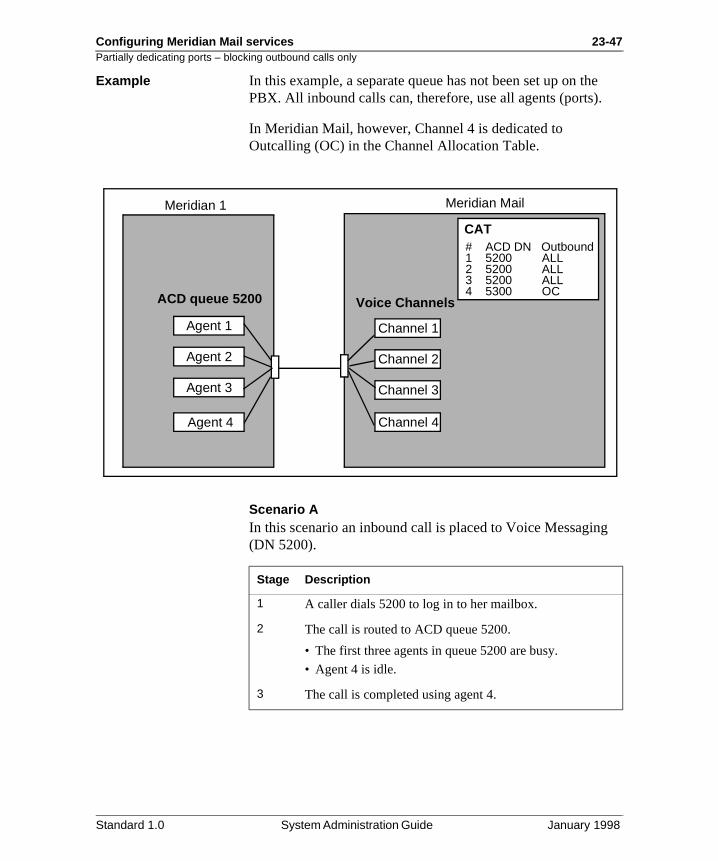
Configuring Meridian Mail services 23-47Partially dedicating ports – blocking outbound calls only
e
g
Example In this example, a separate queue has not been set up on thPBX. All inbound calls can, therefore, use all agents (ports).
In Meridian Mail, however, Channel 4 is dedicated to Outcalling (OC) in the Channel Allocation Table.
Scenario AIn this scenario an inbound call is placed to Voice Messagin(DN 5200).
Agent 1
Agent 2
Agent 3
Channel 1
Channel 2
Channel 3
Channel 4
Meridian 1 Meridian Mail
ACD queue 5200 Voice Channels
CAT# ACD DN Outbound1 5200 ALL2 5200 ALL3 5200 ALL4 5300 OC
Agent 4
Stage Description
1 A caller dials 5200 to log in to her mailbox.
2 The call is routed to ACD queue 5200.
• The first three agents in queue 5200 are busy.
• Agent 4 is idle.
3 The call is completed using agent 4.
Standard 1.0 System Administration Guide January 1998
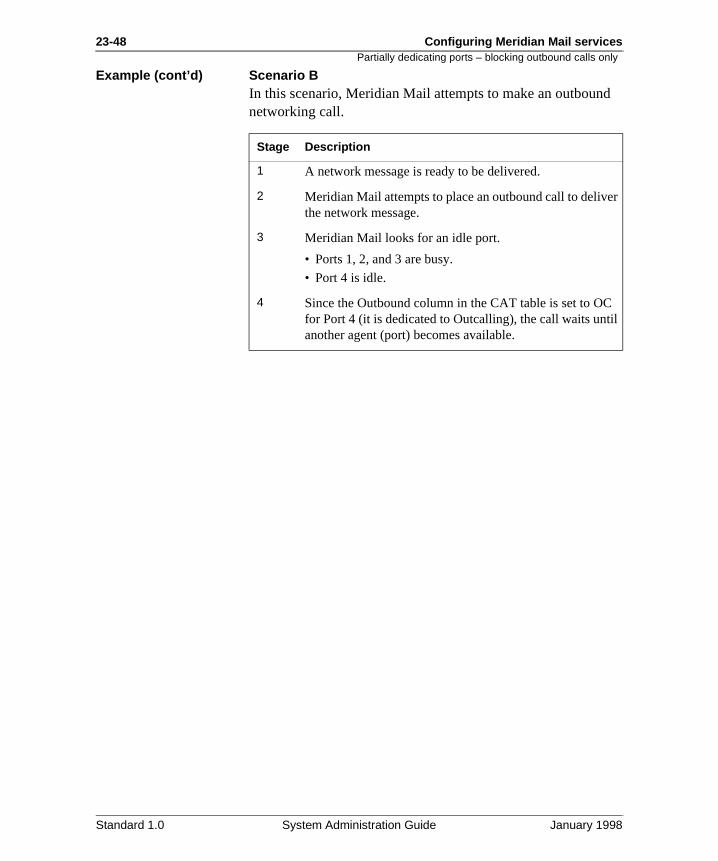
23-48 Configuring Meridian Mail services
d
r
il
Partially dedicating ports – blocking outbound calls only
Example (cont’d) Scenario BIn this scenario, Meridian Mail attempts to make an outbounnetworking call.
Stage Description
1 A network message is ready to be delivered.
2 Meridian Mail attempts to place an outbound call to delivethe network message.
3 Meridian Mail looks for an idle port.
• Ports 1, 2, and 3 are busy.
• Port 4 is idle.
4 Since the Outbound column in the CAT table is set to OCfor Port 4 (it is dedicated to Outcalling), the call waits untanother agent (port) becomes available.
Standard 1.0 System Administration Guide January 1998
Configuring Meridian Mail services 23-49Fully dedicating ports – blocking inbound and outbound calls
.
Fully dedicating ports – blocking inbound and outbound calls
Introduction If you are considering dedicating ports to a service, it is recommended that you fully dedicate them so that no other services can use the ports.
To do this, you must create an agent queue on the PBX and dedicate the port in the Channel Allocation Table in MeridianMail.
Procedure To completely dedicate ports to a service, follow these steps
Step Action See page
Meridian 1 configuration
1 Identify the ports you want to dedicate to the service.
Note: If you have mixed port types on your system, make sure the ports you dedicate are of the correct type, and all of the same type.
23-26
2 Create an agent queue. 23-52
3 Add or move the ports to the queue. 23-55 (add)
23-61 (move)
Meridian Mail configuration
4 Disable the ports you want to dedicate. 23-44
5 Modify the Outbound column in the CAT table. 23-45
6 Reenable the ports. 23-46
Standard 1.0 System Administration Guide January 1998
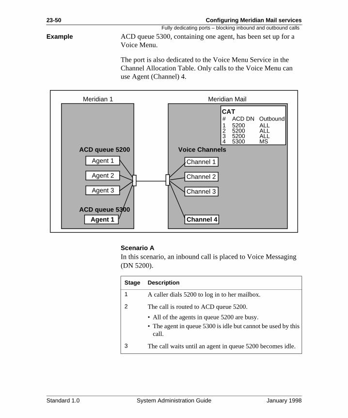
23-50 Configuring Meridian Mail services
a
g
his
.
Fully dedicating ports – blocking inbound and outbound calls
Example ACD queue 5300, containing one agent, has been set up forVoice Menu.
The port is also dedicated to the Voice Menu Service in the Channel Allocation Table. Only calls to the Voice Menu can use Agent (Channel) 4.
Scenario AIn this scenario, an inbound call is placed to Voice Messagin(DN 5200).
Agent 1
Agent 2
Agent 3
Agent 1
Channel 1
Channel 2
Channel 3
Channel 4
Meridian 1 Meridian Mail
ACD queue 5200
ACD queue 5300
Voice Channels
CAT# ACD DN Outbound1 5200 ALL2 5200 ALL3 5200 ALL4 5300 MS
Stage Description
1 A caller dials 5200 to log in to her mailbox.
2 The call is routed to ACD queue 5200.
• All of the agents in queue 5200 are busy.
• The agent in queue 5300 is idle but cannot be used by tcall.
3 The call waits until an agent in queue 5200 becomes idle
Standard 1.0 System Administration Guide January 1998
Configuring Meridian Mail services 23-51Fully dedicating ports – blocking inbound and outbound calls
d
r
e
Example (cont’d) Scenario BIn this scenario, Meridian Mail attempts to make an outbounnetworking call.
Stage Description
1 A network message is ready to be delivered.
2 Meridian Mail attempts to place an outbound call to delivethe network message.
3 Meridian Mail looks for an idle port.
• Ports 1, 2, and 3 are busy.
• Port 4 is idle.
4 Since the Outbound column in the CAT table is set to MSfor this port (it is dedicated to the Voice Menu Service), thcall waits until another port (agent) becomes available.
Standard 1.0 System Administration Guide January 1998
23-52 Configuring Meridian Mail services
at ary
how t
Creating an agent queue
Creating an agent queue
Introduction ACD queues are created using overlay 23. You must set up least one agent queue on the Meridian 1 to serve as the primVoice Messaging queue. This queue is usually set up by theinstall technician.
You may or may not need other agent queues depending on many port types you have on your system and whether or noyou want to dedicate ports to any services.
When to use Create an agent queue
• as the primary Voice Messaging queue (containing full-service voice ports)
• for each additional port type that is installed on your system (basic and/or full multimedia)
• for each service to which you want to dedicate ports
If you are not sure of how many agent queues you require, see “Determining how many ACD queues you need” on page 23-28.
Standard 1.0 System Administration Guide January 1998
Configuring Meridian Mail services 23-53Creating an agent queue
at
e.
n
Procedure To create an agent queue, follow these steps.
Step Action
1 Log in.
2 Enter LD 23 to load overlay 23.
3 Respond to prompts as shown in the following table.
Prompt Response Description
REQ NEW Indicates you are creating a new queue.
TYPE ACD Indicates an ACD data block.
CUST xx Enter the SL-1 customer number (00-31).
ACDN xxxxxxx Enter the DN of the ACD queue. This is the number you enter in the VSDN table.
MWC YES Indicates this is a message center and ththe queue has agents.
IMS YES Indicates an Integrated Messaging servic
CMS YES Command and Status Link Applications Protocol is used.
IMA YES Enables IMS attendant.
IVMS YES Integrated Voice Messaging. Creates a message center from which messages cabe retrieved.
VSID xx Enter the VAS ID (0 to 15) from LD 17.
MAXP xx Indicates the maximum number of ACD agents for this queue.
ALOG YES ACD agents are automatically logged on when Meridian Mail is powered up.
NCFW 0 The DN to which calls are forwarded. Setto 0 for agent queues.
Standard 1.0 System Administration Guide January 1998
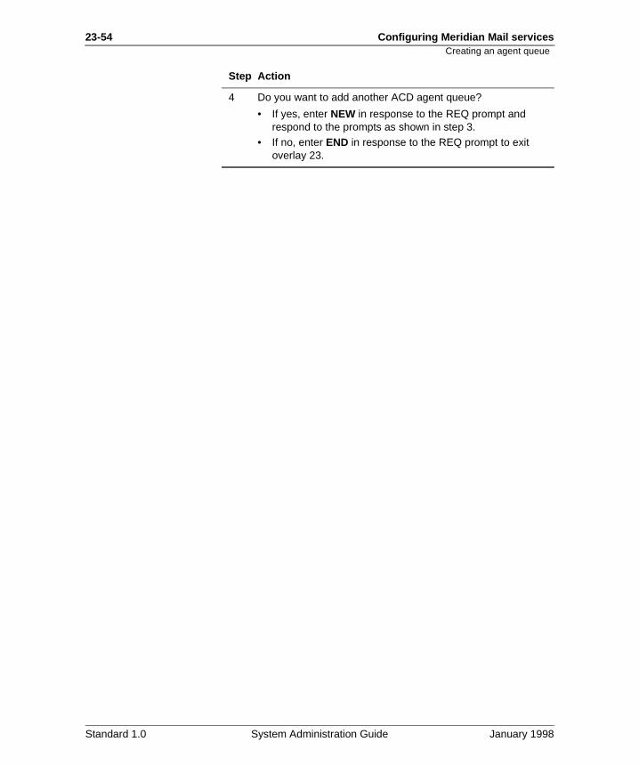
23-54 Configuring Meridian Mail services
Creating an agent queue4 Do you want to add another ACD agent queue?
• If yes, enter NEW in response to the REQ prompt and respond to the prompts as shown in step 3.
• If no, enter END in response to the REQ prompt to exit overlay 23.
Step Action
Standard 1.0 System Administration Guide January 1998
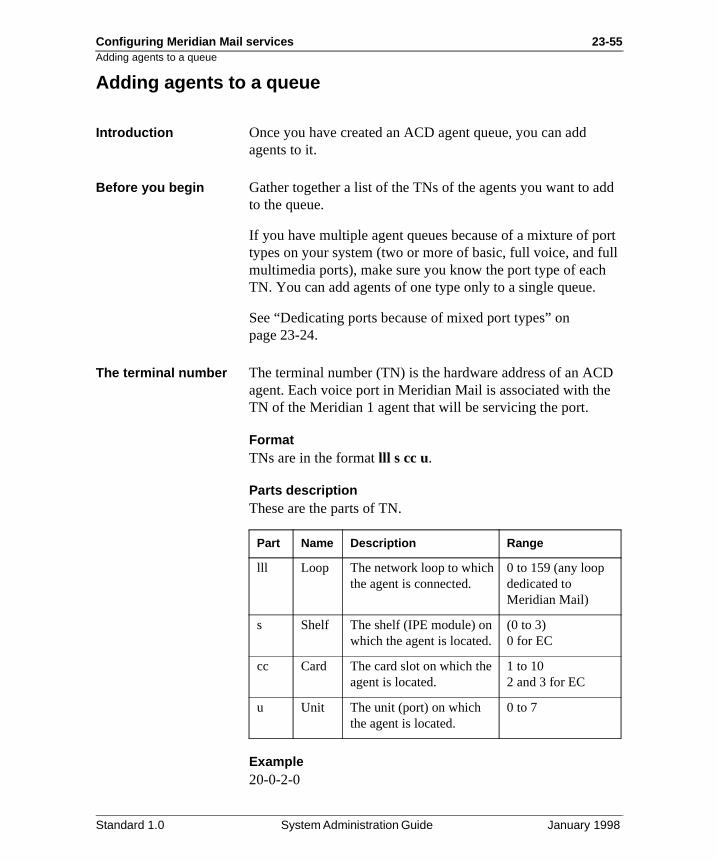
Configuring Meridian Mail services 23-55Adding agents to a queue
dd
ort ll
D e
Adding agents to a queue
Introduction Once you have created an ACD agent queue, you can add agents to it.
Before you begin Gather together a list of the TNs of the agents you want to ato the queue.
If you have multiple agent queues because of a mixture of ptypes on your system (two or more of basic, full voice, and fumultimedia ports), make sure you know the port type of eachTN. You can add agents of one type only to a single queue.
See “Dedicating ports because of mixed port types” on page 23-24.
The terminal number The terminal number (TN) is the hardware address of an ACagent. Each voice port in Meridian Mail is associated with thTN of the Meridian 1 agent that will be servicing the port.
FormatTNs are in the format lll s cc u.
Parts descriptionThese are the parts of TN.
Example20-0-2-0
Part Name Description Range
lll Loop The network loop to which the agent is connected.
0 to 159 (any loop dedicated to Meridian Mail)
s Shelf The shelf (IPE module) on which the agent is located.
(0 to 3) 0 for EC
cc Card The card slot on which the agent is located.
1 to 102 and 3 for EC
u Unit The unit (port) on which the agent is located.
0 to 7
Standard 1.0 System Administration Guide January 1998
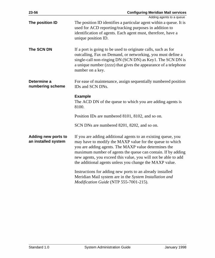
23-56 Configuring Meridian Mail services
is
is one
ition
ing d
Adding agents to a queue
The position ID The position ID identifies a particular agent within a queue. Itused for ACD reporting/tracking purposes in addition to identification of agents. Each agent must, therefore, have a unique position ID.
The SCN DN If a port is going to be used to originate calls, such as for outcalling, Fax on Demand, or networking, you must define asingle-call non-ringing DN (SCN DN) as Key1. The SCN DN a unique number (zzzz) that gives the appearance of a telephnumber on a key.
Determine a numbering scheme
For ease of maintenance, assign sequentially numbered posIDs and SCN DNs.
ExampleThe ACD DN of the queue to which you are adding agents is8100.
Position IDs are numbered 8101, 8102, and so on.
SCN DNs are numbered 8201, 8202, and so on.
Adding new ports to an installed system
If you are adding additional agents to an existing queue, youmay have to modify the MAXP value for the queue to which you are adding agents. The MAXP value determines the maximum number of agents the queue can contain. If by addnew agents, you exceed this value, you will not be able to adthe additional agents unless you change the MAXP value.
Instructions for adding new ports to an already installed Meridian Mail system are in the System Installation and Modification Guide (NTP 555-7001-215).
Standard 1.0 System Administration Guide January 1998
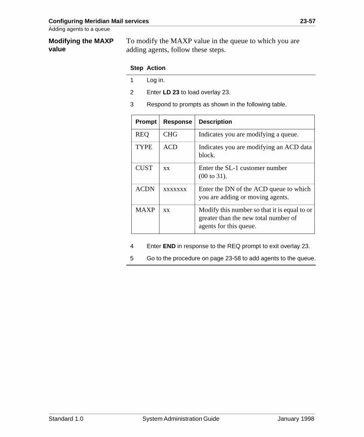
Configuring Meridian Mail services 23-57Adding agents to a queue
Modifying the MAXP value
To modify the MAXP value in the queue to which you are adding agents, follow these steps.
Step Action
1 Log in.
2 Enter LD 23 to load overlay 23.
3 Respond to prompts as shown in the following table.
4 Enter END in response to the REQ prompt to exit overlay 23.
5 Go to the procedure on page 23-58 to add agents to the queue.
Prompt Response Description
REQ CHG Indicates you are modifying a queue.
TYPE ACD Indicates you are modifying an ACD datablock.
CUST xx Enter the SL-1 customer number (00 to 31).
ACDN xxxxxxx Enter the DN of the ACD queue to which you are adding or moving agents.
MAXP xx Modify this number so that it is equal to or greater than the new total number of agents for this queue.
Standard 1.0 System Administration Guide January 1998
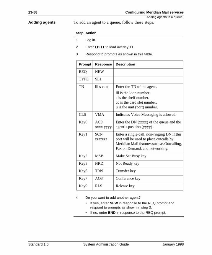
23-58 Configuring Meridian Mail services
Adding agents to a queue
Adding agents To add an agent to a queue, follow these steps.
Step Action
1 Log in.
2 Enter LD 11 to load overlay 11.
3 Respond to prompts as shown in this table.
4 Do you want to add another agent?
• If yes, enter NEW in response to the REQ prompt and respond to prompts as shown in step 3.
• If no, enter END in response to the REQ prompt.
Prompt Response Description
REQ NEW
TYPE SL1
TN lll s cc u Enter the TN of the agent.
lll is the loop number.s is the shelf number.cc is the card slot number.u is the unit (port) number.
CLS VMA Indicates Voice Messaging is allowed.
Key0 ACD xxxx yyyy
Enter the DN (xxxx) of the queue and the agent’s position (yyyy).
Key1 SCN zzzzzzz
Enter a single-call, non-ringing DN if this port will be used to place outcalls by Meridian Mail features such as Outcalling,Fax on Demand, and networking.
Key2 MSB Make Set Busy key
Key3 NRD Not Ready key
Key6 TRN Transfer key
Key7 AO3 Conference key
Key9 RLS Release key
Standard 1.0 System Administration Guide January 1998
Configuring Meridian Mail services 23-59Creating a dummy queue
an
y. ng
so ed.
to nt ced
for
Creating a dummy queue
Introduction A dummy queue does not have agents. Instead, it forwards toagent queue.
When to use Add a dummy queue for each Meridian Mail service that youwant to make directly dialable by users and callers.
ExamplesYou want to provide users with Express Messaging capabilitYou, therefore, create a dummy queue for Express Messagiso that it has a unique DN that can be dialed.
You want to create six Voice Menus that you need to make available to callers. You, therefore, create six dummy queuesthat each Voice Menu has a unique number that can be dial
Systems with mixed port types
If you have more than one port type on your system, be sureforward the dummy queue to the right agent queue. The agequeue to which you forward the dummy queue must be serviby ports of the appropriate type.
To determine the port requirements, see “Port requirementsMeridian Mail services” on page 23-18.
ExampleAll three port types are installed on your system. You have, therefore, created three ACD agent queues as follows.
You need to create a dummy queue for the Fax Item Maintenance service, which requires full-service multimedia ports. You, therefore, enter 7480 as the NCFW DN. This forwards the dummy queue to the agent queue that containsfull-service multimedia ports.
ACD agent queue DN Contains
7400 Full-service voice ports
7440 Basic service ports
7480 Full-service multimedia ports
Standard 1.0 System Administration Guide January 1998
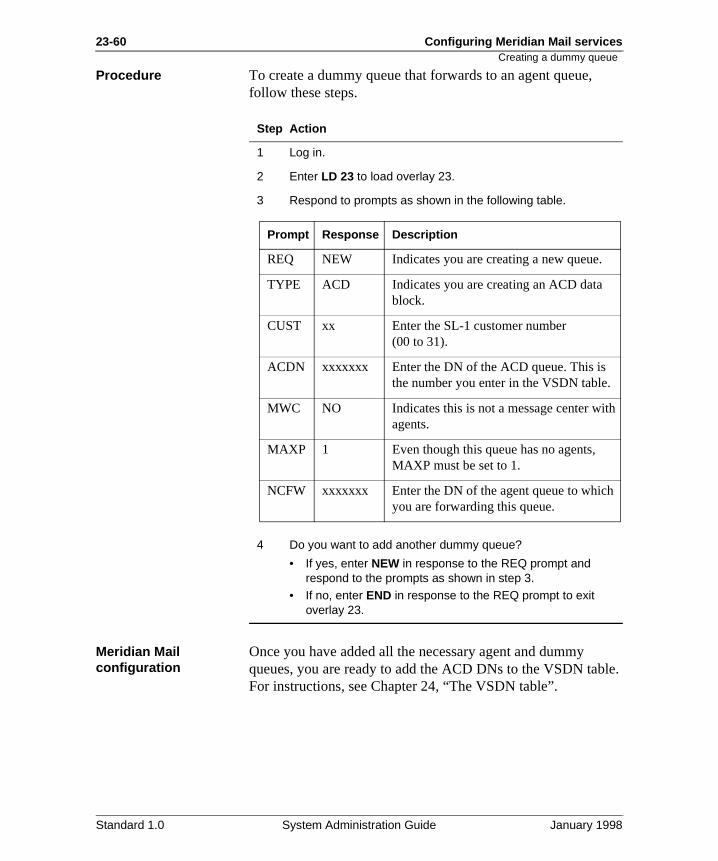
23-60 Configuring Meridian Mail services
le.
h
Creating a dummy queue
Procedure To create a dummy queue that forwards to an agent queue, follow these steps.
Meridian Mail configuration
Once you have added all the necessary agent and dummy queues, you are ready to add the ACD DNs to the VSDN tabFor instructions, see Chapter 24, “The VSDN table”.
Step Action
1 Log in.
2 Enter LD 23 to load overlay 23.
3 Respond to prompts as shown in the following table.
4 Do you want to add another dummy queue?
• If yes, enter NEW in response to the REQ prompt and respond to the prompts as shown in step 3.
• If no, enter END in response to the REQ prompt to exit overlay 23.
Prompt Response Description
REQ NEW Indicates you are creating a new queue.
TYPE ACD Indicates you are creating an ACD data block.
CUST xx Enter the SL-1 customer number (00 to 31).
ACDN xxxxxxx Enter the DN of the ACD queue. This is the number you enter in the VSDN table.
MWC NO Indicates this is not a message center witagents.
MAXP 1 Even though this queue has no agents, MAXP must be set to 1.
NCFW xxxxxxx Enter the DN of the agent queue to whichyou are forwarding this queue.
Standard 1.0 System Administration Guide January 1998
Configuring Meridian Mail services 23-61Moving agents from one queue to another
es
can
s ay ns, he
Moving agents from one queue to another
Introduction You must follow this procedure to move agents. You cannotsimply change the ACD DN of an existing agent.
When to use Use this procedure if you want to move existing agents fromone queue to another queue.
ExamplesYou might need to do this if you have dedicated ports to a particular service and you find through analyzing traffic studithat you need more ports.
Or, you might find that the efficiency of the system has gonedown, and you want to reduce the number of ports that are dedicated to a service and move them to a queue where theybe shared among more services.
Modifying MAXP The MAXP value determines the maximum number of agentthat can be in a queue. By moving agents to a queue, you mexceed the current MAXP value for that queue. If this happeyou must modify MAXP so that it is equal to or greater than tnew total number of agents.
CAUTION
Risk of data corruption
Do not move ACD agents by changing the ACD DN (on Key0) of an existing agent. Doing this can cause severe data corruption.
Standard 1.0 System Administration Guide January 1998
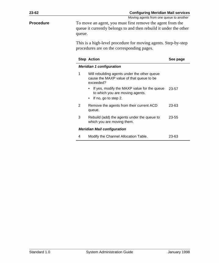
23-62 Configuring Meridian Mail services
her
ep
Moving agents from one queue to another
Procedure To move an agent, you must first remove the agent from thequeue it currently belongs to and then rebuild it under the otqueue.
This is a high-level procedure for moving agents. Step-by-stprocedures are on the corresponding pages.
Step Action See page
Meridian 1 configuration
1 Will rebuilding agents under the other queue cause the MAXP value of that queue to be exceeded?
• If yes, modify the MAXP value for the queue to which you are moving agents.
• If no, go to step 2.
23-57
2 Remove the agents from their current ACD queue.
23-63
3 Rebuild (add) the agents under the queue to which you are moving them.
23-55
Meridian Mail configuration
4 Modify the Channel Allocation Table. 23-63
Standard 1.0 System Administration Guide January 1998
Configuring Meridian Mail services 23-63Removing agents from a queue
ue
e
Removing agents from a queue
When to use Use this procedure if you need to move agents from one queto another. Moving agents involves removing them from the queue they currently belong to and rebuilding them under thnew queue.
Procedure To remove an agent from a queue, follow these steps.
Step Action
1 Log in.
2 Enter LD 11 to enter overlay 11.
3 Respond to prompts as shown in the following table.
4 Do you want to remove another agent?
• If yes, enter OUT in response to the REQ prompt and respond to the prompts as shown in step 3.
• If no, enter END in response to the REQ prompt to exit overlay 11.
Prompt Response Description
REQ OUT Indicates you want to out (remove) an agent.
TYPE SL1
TN lll s cc u Enter the TN of the agent you want to remove.
lll is the loop number.s is the shelf number.cc is the card slot number.u is the unit (port) number.
Standard 1.0 System Administration Guide January 1998
23-64 Configuring Meridian Mail services
D he
Modifying the Channel Allocation Table after moving agents
Modifying the Channel Allocation Table after moving agents
When to use You need to modify the Channel Allocation Table only if youhave moved agents from one queue to another.
When you move an agent from one queue to another, the ACDN of the agent changes. This change must be reflected in tChannel Allocation Table (CAT).
Procedure To modify the ACD DN of moved agents in the Channel Allocation table, follow these steps.
Starting Point: The Main Menu
Step Action
1 Select System Status and Maintenance.
2 Disable the ports that correspond to the moved agents.
Note: See “Disabling ports” on page 23-44.
3 Select Channel Allocation Table from the System Status and Maintenance menu.
Result: The Channel Allocation Table is displayed.
4 Move the cursor to the agent (port) that was moved.
5 Go to the ACD DN column and enter the DN of the ACD queue to which it was moved.
Standard 1.0 System Administration Guide January 1998
Configuring Meridian Mail services 23-65Modifying the Channel Allocation Table after moving agents
6 Did you move any other agents (ports)?
• If yes, repeat steps 4 to 5 until you have modified the ACD DNs of all agents that were moved.
• If no, go to step 8.
7 Press [Save] to save the changes.
8 Reenable the port(s).
Note: See “Reenabling the ports” on page 23-46.
Step Action
Standard 1.0 System Administration Guide January 1998
23-66 Configuring Meridian Mail services
Modifying the Channel Allocation Table after moving agentsStandard 1.0 System Administration Guide January 1998
Chapter 24
The VSDN table
In this chapter
Section A: Introduction 24-3
Section B: Adding messaging VSDNs 24-11
Section C: Adding networking and ACCESS VSDNs 24-27
Section D: Adding voice service and fax service DNs 24-39
Section E: Session profiles 24-67
Section F: Viewing, modifying, and deleting VSDNs 24-115

24-2 The VSDN table
Standard 1.0 System Administration Guide January 1998
The VSDN table 24-3
Section A: Introduction
In this section
Overview 24-4
When to create a VSDN 24-5
Network Message Service requirements 24-6
Network Message Service requirements 24-6
The VSDN table 24-9
Standard 1.0 System Administration Guide January 1998
24-4 The VSDN table Overview
ry
s not es
Overview
Introduction Voice service directory numbers (VSDNs) are defined for eveservice that you want to make directly accessible to internal users or external callers, or both. These directory numbers (DNs) are entered in the Voice Services-DN (VSDN) table which maps DNs to services.
Access DNs Part of defining a VSDN is specifying the access DN. This isthe number that users and callers dial to access the service.
Nightly audits Every day at 3:30 a.m., Meridian Mail performs an audit. Thiaudit can take anywhere from 10 minutes (if the system has been modified since the last audit) to 2 hours (if many changhave been made, such as users or services being added or modified).
ATTENTION
Ensure that access DNs in your VSDN definitions do not duplicate mailbox numbers or Meridian 1 trunk route access codes.
ATTENTION
Do not add, modify, or delete VSDNs during the nightly audit.
Standard 1.0 System Administration Guide January 1998
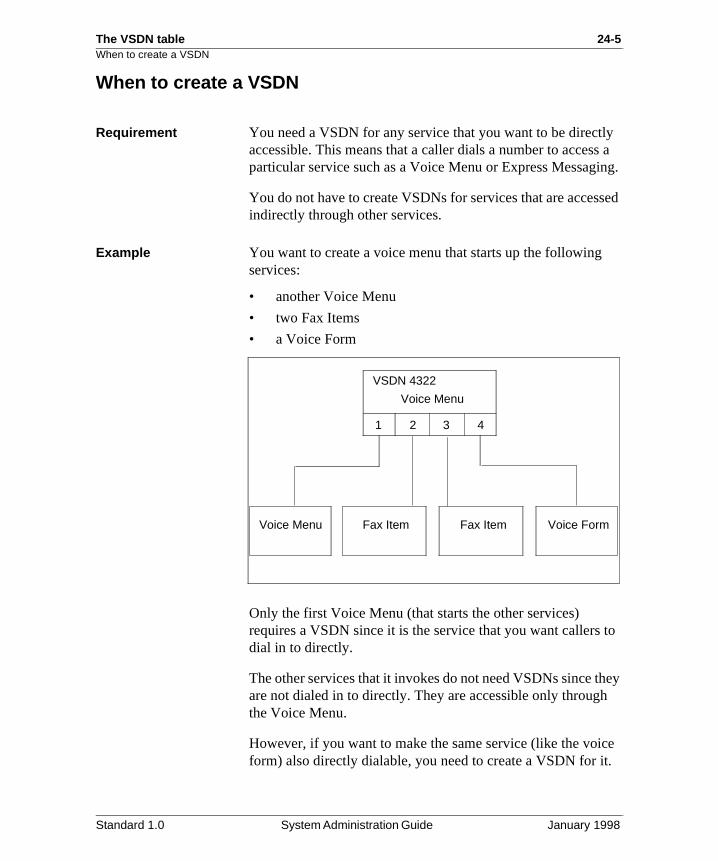
The VSDN table 24-5When to create a VSDN
ly s a ing.
sed
to
hey
e .
When to create a VSDN
Requirement You need a VSDN for any service that you want to be directaccessible. This means that a caller dials a number to accesparticular service such as a Voice Menu or Express Messag
You do not have to create VSDNs for services that are accesindirectly through other services.
Example You want to create a voice menu that starts up the followingservices:
• another Voice Menu
• two Fax Items
• a Voice Form
Only the first Voice Menu (that starts the other services) requires a VSDN since it is the service that you want callersdial in to directly.
The other services that it invokes do not need VSDNs since tare not dialed in to directly. They are accessible only throughthe Voice Menu.
However, if you want to make the same service (like the voicform) also directly dialable, you need to create a VSDN for it
Voice Menu
1 2 3 4
Voice Menu Fax Item Fax Item Voice Form
VSDN 4322
Standard 1.0 System Administration Guide January 1998
24-6 The VSDN table Network Message Service requirements
ou
all
r
tion
e
il. g
is
is
Network Message Service requirements
NMS networks If the Network Message Service (NMS) feature is installed, ymust create a VSDN for each location at which you need a particular service.
Example There are three NMS locations in your network: the prime location (the switch connected to Meridian Mail) and two satellite locations. You want to provide express messaging tothree locations. You, therefore, need to add three express messaging VSDNs, one for each NMS location.
DN format for the prime location
When adding VSDNs for services at the prime location, entethem in the local format.
ExampleYou create a VSDN for express messaging at the prime locawith an access DN of 8365.
DN format for satellite locations
When adding a VSDN for a service at a satellite location, theaccess DN must be in a format which is dialable from the primlocation, since this is what the switch passes to Meridian MaConsequently, it must include the ESN prefix or CDP steerincode for the satellite location.
ExampleYou have an ESN dialing plan:
• The ESN prefix for satellite location 1 is 6444.
• The ESN prefix for satellite location 2 is 6555.
• The local extension for express messaging at satellite location 1 is 3544.
• The local extension for express messaging at satellite location 2 is 3652.
The access DN for express messaging at satellite location 164443544.
The access DN for express messaging at satellite location 265553652.
Standard 1.0 System Administration Guide January 1998
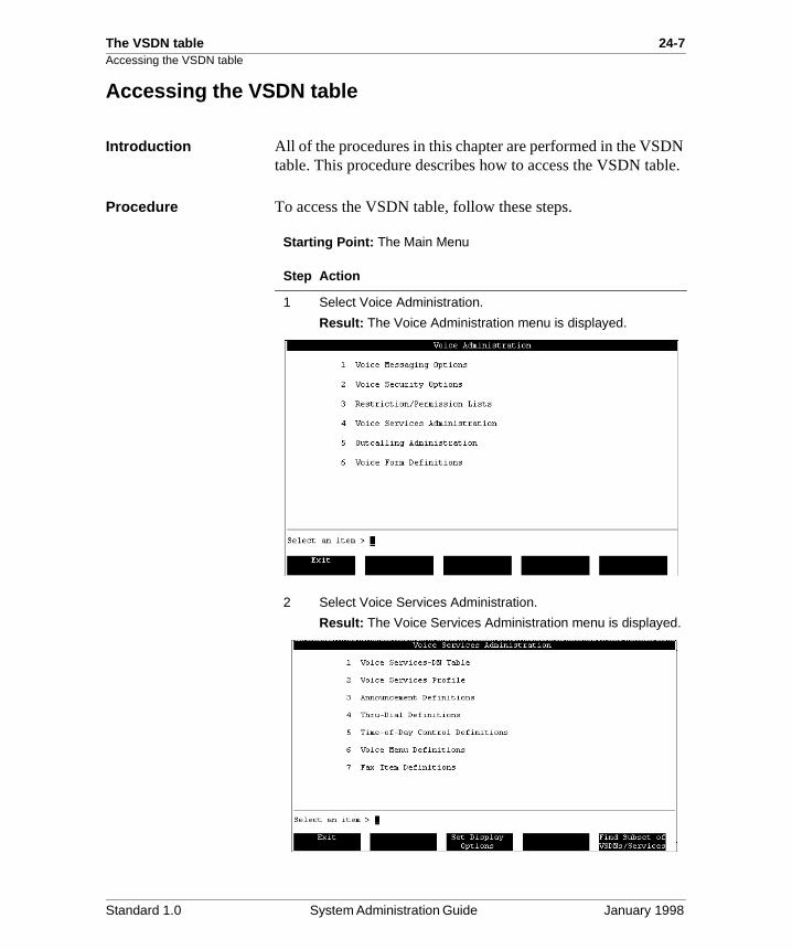
The VSDN table 24-7Accessing the VSDN table
N ble.
Accessing the VSDN table
Introduction All of the procedures in this chapter are performed in the VSDtable. This procedure describes how to access the VSDN ta
Procedure To access the VSDN table, follow these steps.
Starting Point: The Main Menu
Step Action
1 Select Voice Administration.
Result: The Voice Administration menu is displayed.
2 Select Voice Services Administration.
Result: The Voice Services Administration menu is displayed.
Standard 1.0 System Administration Guide January 1998
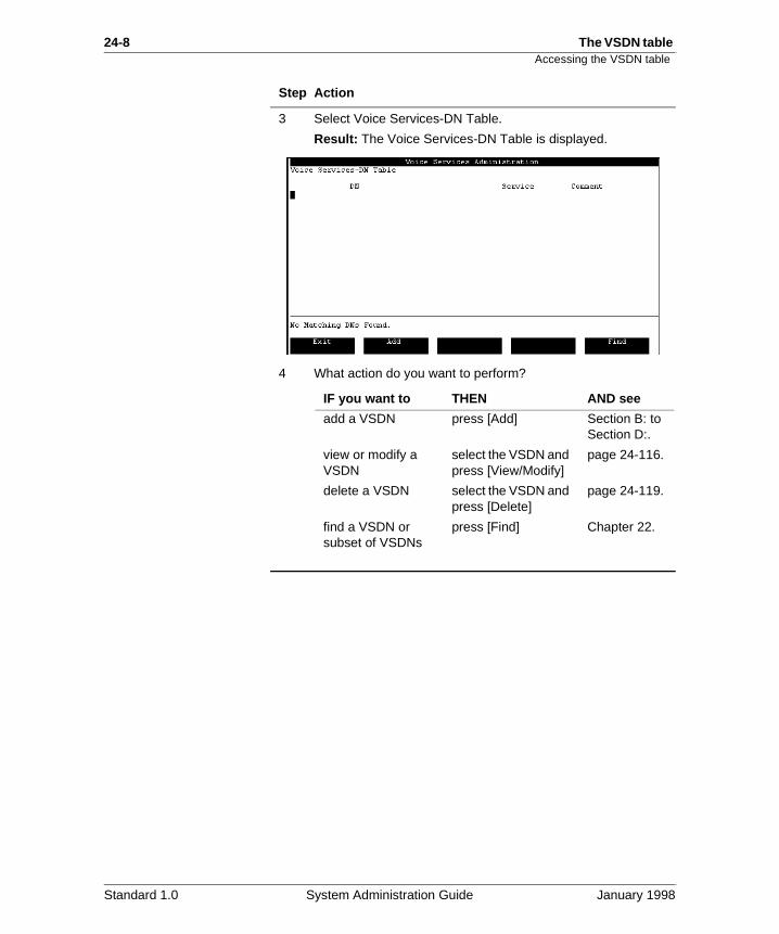
24-8 The VSDN table Accessing the VSDN table
3 Select Voice Services-DN Table.
Result: The Voice Services-DN Table is displayed.
4 What action do you want to perform?
Step Action
IF you want to THEN AND see
add a VSDN press [Add] Section B: to Section D:.
view or modify a VSDN
select the VSDN and press [View/Modify]
page 24-116.
delete a VSDN select the VSDN and press [Delete]
page 24-119.
find a VSDN or subset of VSDNs
press [Find] Chapter 22.
Standard 1.0 System Administration Guide January 1998
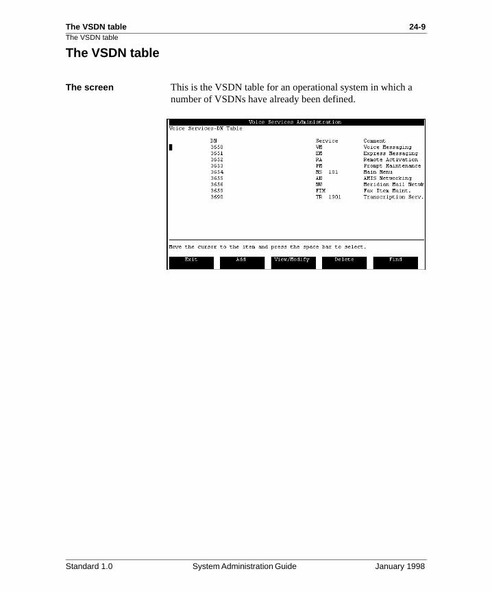
The VSDN table 24-9The VSDN table
The VSDN table
The screen This is the VSDN table for an operational system in which a number of VSDNs have already been defined.
Standard 1.0 System Administration Guide January 1998
24-10 The VSDN table The VSDN table
e
is
d
ed
Field descriptions This table describes the fields in the VSDN table.
DN
Description This is the directory number of the service. It is thnumber that is dialed to access the service.
Service
Description This is the service that is accessed when the DNdialed. Only the service acronym is displayed.
ID For certain services, such as Announcements anVoice Menus, an ID is displayed next to the acronym. This is the specific service that is accessed.
Comment
Description This is a description or title that has been assignto the VSDN.
Standard 1.0 System Administration Guide January 1998
The VSDN table 24-11
Section B: Adding messaging VSDNs
In this section
Overview 24-12
Adding a VSDN for Voice Messaging 24-13
Adding a VSDN for Express Messaging 24-15
Adding a VSDN for Call Answering 24-17
Adding a VSDN for hospitality voice messaging 24-19
Adding a VSDN for the Post-Checkout Mailbox service 24-22
Adding a VSDN for the Greetings Service 24-24
Standard 1.0 System Administration Guide January 1998
24-12 The VSDN table Overview
ing
ur
Overview
Introduction This section describes how to add VSDNs for Voice Messagservices.
Deciding which VSDNs you need
Use this table to decide which VSDNs you need to add to yosystem.
IF THEN AND see
MMUI or VMUIF Voice Messaging is installed
create a VSDN for VM page 24-13.
you want express messaging
create a VSDN for EM page 24-15.
you want express messaging to a particular mailbox with voice messaging-style prompts
create a VSDN for CA page 24-17.
Hospitality voice messaging is installed
create a VSDN for HM (instead of VM) and CO
pages 24-19 and 24-22.
VMUIF voice messaging is installed
create a VSDN for GS page 24-24.
Standard 1.0 System Administration Guide January 1998
The VSDN table 24-13Adding a VSDN for Voice Messaging
ing)
ee
See
Adding a VSDN for Voice Messaging
Description Voice Messaging is the basic voice mail service that recordsvoice messages when a phone is not answered (Call Answerand allows users to compose and send voice messages.
When to use Add a VSDN for the Voice Messaging service during initial Meridian Mail setup.
Hospitality systems If Hospitality Voice Messaging is installed on your system, s“Adding a VSDN for hospitality voice messaging” on page 24-19 instead.
If installed, you can also add a DN for the Post-Checkout Mailbox service, as described on page 24-22.
Before you begin Access the VSDN table if you are not already at the screen. “Accessing the VSDN table” on page 24-7.
Procedure To add the Voice Messaging VSDN, follow these steps.
Starting Point: The VSDN table
Step Action
1 Press the [Add] softkey.
Result: The Add DN Information screen is displayed.
2 Enter the Access DN.
Note: This is the DN of the primary ACD agent queue.
Standard 1.0 System Administration Guide January 1998
24-14 The VSDN table Adding a VSDN for Voice Messaging
3 Enter VM in the Service field.
4 Enter an optional comment in the Comment field.
5 Do you want to add the VSDN with the information you have entered?
• If yes, press the [Save] softkey.• If no, press [Cancel], or make any necessary corrections
and then press [Save].
Result: You are returned to the VSDN table. If you pressed the [Save] softkey, there is now a new entry in the table for this DN.
Step Action
Standard 1.0 System Administration Guide January 1998
The VSDN table 24-15Adding a VSDN for Express Messaging
in
le to ss n
.
ach
d, x)
ng
See
Adding a VSDN for Express Messaging
Description Express Messaging allows users to directly leave a messageanother user’s mailbox without ringing a phone.
When to use Express Messaging is a basic feature that should be availabusers once Meridian Mail is operational. The VSDN for ExpreMessaging should, therefore, be added during initial MeridiaMail setup.
Mailbox ID If you define a Mailbox ID, callers to the Express Messagingservice are automatically transferred to the specified mailbox
Types of express messaging services
You can create a number of Express Messaging services, ewith its own VSDN.
Application 1: general Express Messaging serviceThis is the typical Express Messaging application that allowsusers to activate the Express Messaging service, dial any mailbox without ringing the associated phone, and leave a message directly in the mailbox.
For this type of service, do not enter a mailbox ID.
Application 2: suggestion boxIn this application, when the Express Messaging DN is dialethe caller is forwarded to a specific mailbox (a suggestion boto leave a message.
This application requires that you
• set up a special mailbox just for this purpose. (See “Addia local voice user” on page 8-6.)
• enter the mailbox ID in the Add DN Information screen
Before you begin Access the VSDN table if you are not already at the screen. “Accessing the VSDN table” on page 24-7.
Standard 1.0 System Administration Guide January 1998
24-16 The VSDN table Adding a VSDN for Express Messaging
Procedure To add the Express Messaging VSDN, follow these steps.
Starting Point: The VSDN table
Step Action
1 Press the [Add] softkey.
Result: The Add DN Information screen is displayed.
2 Enter the Access DN.
3 Enter EM in the Service field.
Result: The Mailbox ID field is displayed.
4 Do you want callers to be forwarded to a particular mailbox when using this service?
• If yes, enter the number of the mailbox to which you want to forward users in the Mailbox ID field.
• If no, leave the Mailbox ID field blank.
5 Enter an optional comment in the Comment field.
6 Do you want to add the VSDN with the information you have entered?
• If yes, press the [Save] softkey.• If no, press [Cancel], or make any necessary corrections
and then press [Save].
Result: You are returned to the VSDN table. If you pressed the [Save] softkey, there is now a new entry in the table for this DN.
Standard 1.0 System Administration Guide January 1998
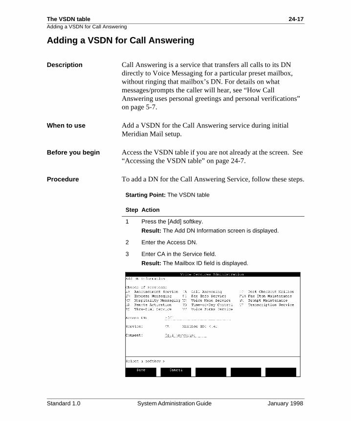
The VSDN table 24-17Adding a VSDN for Call Answering
s”
See
ps.
Adding a VSDN for Call Answering
Description Call Answering is a service that transfers all calls to its DN directly to Voice Messaging for a particular preset mailbox, without ringing that mailbox’s DN. For details on what messages/prompts the caller will hear, see “How Call Answering uses personal greetings and personal verificationon page 5-7.
When to use Add a VSDN for the Call Answering service during initial Meridian Mail setup.
Before you begin Access the VSDN table if you are not already at the screen. “Accessing the VSDN table” on page 24-7.
Procedure To add a DN for the Call Answering Service, follow these ste
Starting Point: The VSDN table
Step Action
1 Press the [Add] softkey.
Result: The Add DN Information screen is displayed.
2 Enter the Access DN.
3 Enter CA in the Service field.
Result: The Mailbox ID field is displayed.
Standard 1.0 System Administration Guide January 1998
24-18 The VSDN table Adding a VSDN for Call Answering
4 Enter the number of the user’s mailbox in the Mailbox ID field. All calls to this Call Answering service will be transferred directly to that mailbox.
5 Enter an optional comment in the Comment field.
6 Do you want to add the VSDN with the information you have just entered?
• If yes, press the [Save] softkey.• If no, press [Cancel], or make any necessary corrections
and then press [Save].
Result: You are returned to the VSDN table. If you pressed the [Save] softkey, there is now a new entry in the table for this DN.
Step Action
Standard 1.0 System Administration Guide January 1998
The VSDN table 24-19Adding a VSDN for hospitality voice messaging
at ice nd
es:
lity
Adding a VSDN for hospitality voice messaging
Description Hospitality voice messaging is the basic voice mail service this used when Hospitality is installed. This service records vomessages when a phone is not answered (call answering) aallows users to compose and send voice messages.
In addition to these regular voice messaging features, hospitality voice messaging has two additional telset interfacone for guests and one for staff.
When to use If you have a Hospitality Meridian Mail system, follow this procedure for adding the hospitality voice messaging VSDNinstead of the one on page 24-13. Add the VSDN for hospitavoice messaging during initial Meridian Mail setup.
Auto logon When you add the DN for hospitality voice messaging, you must specify if auto logon is enabled or disabled.
This is how auto logon works.
WHEN auto logon is THEN guests and staff
enabled • can log on to their mailboxes without entering the mailbox number and password when calling in from their own phone.
• must enter their mailbox number and password if calling from a phone that has a mailbox with auto logon disabledor does not have a mailbox associatedwith it.
disabled must enter their mailbox number and password to log on regardless of which phone they use to log on (their own or someone else’s phone).
Standard 1.0 System Administration Guide January 1998
24-20 The VSDN table Adding a VSDN for hospitality voice messaging
he be
e in
See
Auto logon in the user profile
There is also an Auto logon field in the Add and View/ModifyLocal Voice User screen.
Both of these fields (in the Add DN Information screen and tAdd Local Voice User screen) must be enabled for users to able to auto logon.
This table shows how these two fields interact.
Multiple voice messaging services
You can create two hospitality voice messaging services: onwhich auto logon is disabled and one in which it is enabled.
Before you begin Access the VSDN table if you are not already at the screen. “Accessing the VSDN table” on page 24-7.
WHEN the VSDN setting is
AND the local voice user setting is THEN the user
enabled enabled can auto logon.
enabled disabled cannot auto logon.
disabled enabled cannot auto logon.
disabled disabled cannot auto logon.
Standard 1.0 System Administration Guide January 1998
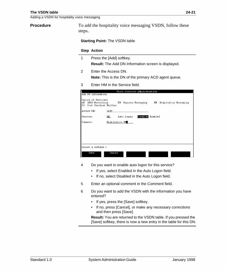
The VSDN table 24-21Adding a VSDN for hospitality voice messaging
Procedure To add the hospitality voice messaging VSDN, follow these steps.
Starting Point: The VSDN table
Step Action
1 Press the [Add] softkey.
Result: The Add DN Information screen is displayed.
2 Enter the Access DN.
Note: This is the DN of the primary ACD agent queue.
3 Enter HM in the Service field.
4 Do you want to enable auto logon for this service?
• If yes, select Enabled in the Auto Logon field.• If no, select Disabled in the Auto Logon field.
5 Enter an optional comment in the Comment field.
6 Do you want to add the VSDN with the information you have entered?
• If yes, press the [Save] softkey.
• If no, press [Cancel], or make any necessary corrections and then press [Save].
Result: You are returned to the VSDN table. If you pressed the [Save] softkey, there is now a new entry in the table for this DN.
Standard 1.0 System Administration Guide January 1998
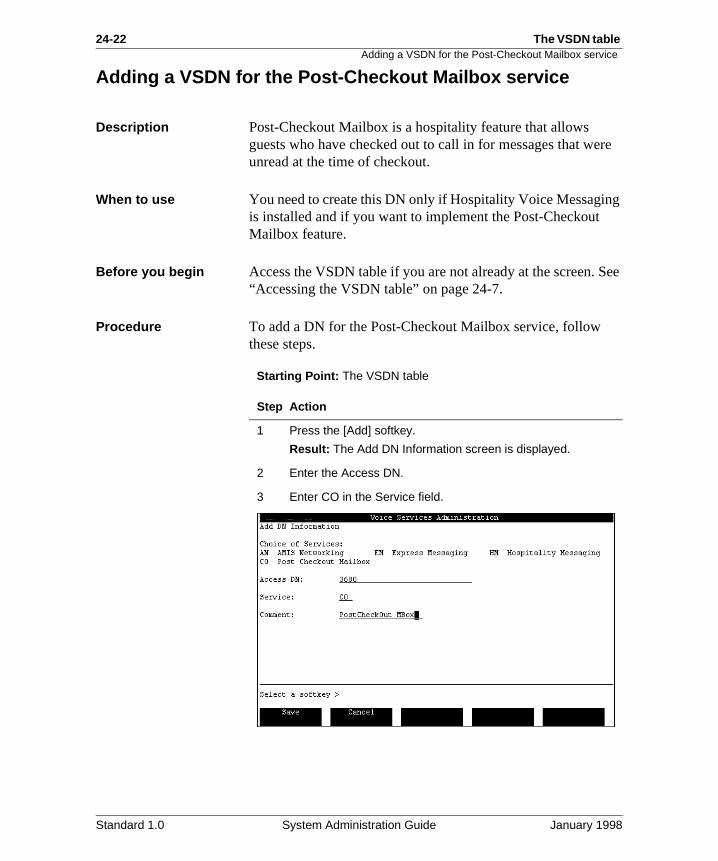
24-22 The VSDN table Adding a VSDN for the Post-Checkout Mailbox service
re
g
See
Adding a VSDN for the Post-Checkout Mailbox service
Description Post-Checkout Mailbox is a hospitality feature that allows guests who have checked out to call in for messages that weunread at the time of checkout.
When to use You need to create this DN only if Hospitality Voice Messaginis installed and if you want to implement the Post-Checkout Mailbox feature.
Before you begin Access the VSDN table if you are not already at the screen. “Accessing the VSDN table” on page 24-7.
Procedure To add a DN for the Post-Checkout Mailbox service, follow these steps.
Starting Point: The VSDN table
Step Action
1 Press the [Add] softkey.
Result: The Add DN Information screen is displayed.
2 Enter the Access DN.
3 Enter CO in the Service field.
Standard 1.0 System Administration Guide January 1998
The VSDN table 24-23Adding a VSDN for the Post-Checkout Mailbox service
4 Enter an optional comment in the Comment field.
5 Do you want to add the VSDN with the information you have entered?
• If yes, press the [Save] softkey.• If no, press [Cancel], or make any necessary corrections
and then press [Save].
Result: You are returned to the VSDN table. If you pressed the [Save] softkey, there is now a new entry in the table for this DN.
Step Action
Standard 1.0 System Administration Guide January 1998
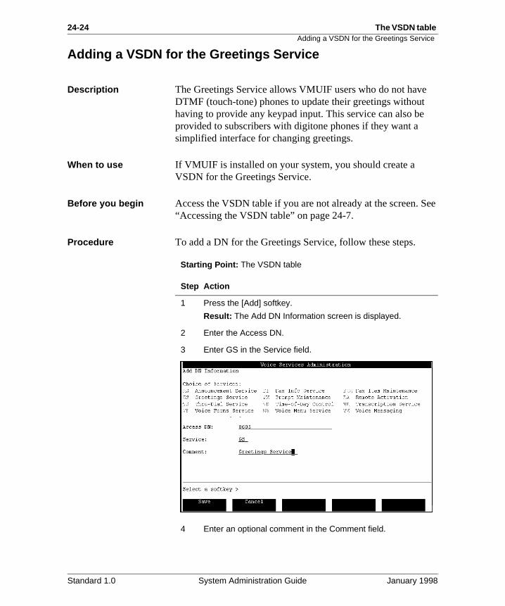
24-24 The VSDN table Adding a VSDN for the Greetings Service
See
Adding a VSDN for the Greetings Service
Description The Greetings Service allows VMUIF users who do not haveDTMF (touch-tone) phones to update their greetings withouthaving to provide any keypad input. This service can also beprovided to subscribers with digitone phones if they want a simplified interface for changing greetings.
When to use If VMUIF is installed on your system, you should create a VSDN for the Greetings Service.
Before you begin Access the VSDN table if you are not already at the screen. “Accessing the VSDN table” on page 24-7.
Procedure To add a DN for the Greetings Service, follow these steps.
Starting Point: The VSDN table
Step Action
1 Press the [Add] softkey.
Result: The Add DN Information screen is displayed.
2 Enter the Access DN.
3 Enter GS in the Service field.
4 Enter an optional comment in the Comment field.
Standard 1.0 System Administration Guide January 1998
The VSDN table 24-25Adding a VSDN for the Greetings Service
5 Do you want to add the VSDN with the information you have entered?
• If yes, press the [Save] softkey.• If no, press [Cancel], or make any necessary corrections
and then press [Save].
Result: You are returned to the VSDN table. If you pressed the [Save] softkey, there is now a new entry in the table for this DN.
Step Action
Standard 1.0 System Administration Guide January 1998

24-26 The VSDN table Adding a VSDN for the Greetings Service
Standard 1.0 System Administration Guide January 1998
The VSDN table 24-27
Section C: Adding networking and ACCESS VSDNs
In this section
Overview 24-28
Adding a VSDN for AMIS Networking 24-29
Adding a VSDN for Meridian Networking 24-31
Adding a VSDN for Enterprise Networking 24-33
Adding a VSDN for a Meridian ACCESS application 24-36
Standard 1.0 System Administration Guide January 1998
24-28 The VSDN table Overview
at
this in ill
n
e
Overview
Enterprise Networking Meridian Mail offers three types of networking capabilities thinclude AMIS Networking, Meridian Networking, and Enterprise Networking.
A VSDN is required for Enterprise Networking if you are expanding to Enterprise Networking or if you are adding Enterprise Networking.
AMIS and Enterprise Networking
When both AMIS Networking and Enterprise Networking areinstalled, they can share the same VSDN. The drawback to method is that you will not be able to see separate statistics Operational Measurements for these two services as they wbe combined.
If both AMIS and Enterprise Networking are installed, you cado any one of the following:
• Create two separate VSDNs, one for AMIS (AN) and onfor Enterprise Networking (EN).
• Create only one VSDN for AN that is shared by both networking types.
• Create only one VSDN for EN that is shared by both networking types.
Standard 1.0 System Administration Guide January 1998
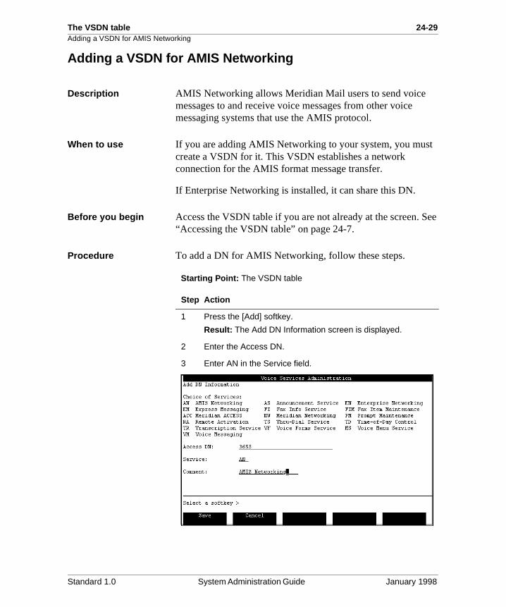
The VSDN table 24-29Adding a VSDN for AMIS Networking
t
See
Adding a VSDN for AMIS Networking
Description AMIS Networking allows Meridian Mail users to send voice messages to and receive voice messages from other voice messaging systems that use the AMIS protocol.
When to use If you are adding AMIS Networking to your system, you muscreate a VSDN for it. This VSDN establishes a network connection for the AMIS format message transfer.
If Enterprise Networking is installed, it can share this DN.
Before you begin Access the VSDN table if you are not already at the screen. “Accessing the VSDN table” on page 24-7.
Procedure To add a DN for AMIS Networking, follow these steps.
Starting Point: The VSDN table
Step Action
1 Press the [Add] softkey.
Result: The Add DN Information screen is displayed.
2 Enter the Access DN.
3 Enter AN in the Service field.
Standard 1.0 System Administration Guide January 1998

24-30 The VSDN table Adding a VSDN for AMIS Networking
4 Enter an optional comment in the Comment field.
5 Do you want to add the VSDN with the information you have entered?
• If yes, press the [Save] softkey.• If no, press [Cancel], or make any necessary corrections
and then press [Save].
Result: You are returned to the VSDN table. If you pressed the [Save] softkey, there is now a new entry in the table for this DN.
Step Action
Standard 1.0 System Administration Guide January 1998
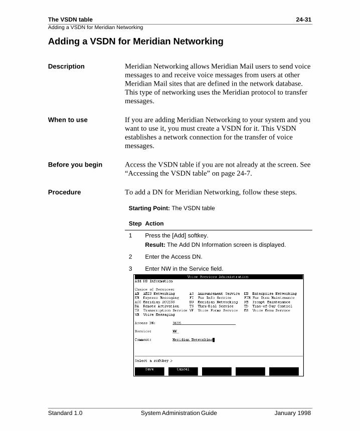
The VSDN table 24-31Adding a VSDN for Meridian Networking
e r
. r
u
See
Adding a VSDN for Meridian Networking
Description Meridian Networking allows Meridian Mail users to send voicmessages to and receive voice messages from users at otheMeridian Mail sites that are defined in the network databaseThis type of networking uses the Meridian protocol to transfemessages.
When to use If you are adding Meridian Networking to your system and yowant to use it, you must create a VSDN for it. This VSDN establishes a network connection for the transfer of voice messages.
Before you begin Access the VSDN table if you are not already at the screen. “Accessing the VSDN table” on page 24-7.
Procedure To add a DN for Meridian Networking, follow these steps.
Starting Point: The VSDN table
Step Action
1 Press the [Add] softkey.
Result: The Add DN Information screen is displayed.
2 Enter the Access DN.
3 Enter NW in the Service field.
Standard 1.0 System Administration Guide January 1998
24-32 The VSDN table Adding a VSDN for Meridian Networking
4 Enter an optional comment in the Comment field.
5 Do you want to add the VSDN with the information you have entered?
• If yes, press the [Save] softkey.• If no, press [Cancel], or make any necessary corrections
and then press [Save].
Result: You are returned to the VSDN table. If you pressed the [Save] softkey, there is now a new entry in the table for this DN.
Step Action
Standard 1.0 System Administration Guide January 1998
The VSDN table 24-33Adding a VSDN for Enterprise Networking
e
is ice
r
See
Adding a VSDN for Enterprise Networking
Description Enterprise Networking provides most of the functionality of Meridian Networking, but uses DTMF signaling, based on thAMIS protocol, instead of modems to transmit messages.
The Remote Voice User Propagation feature is unique to Enterprise Networking. It allows you to automatically add temporary remote voice users to your system.
When to use If you are adding Enterprise Networking to your system and you want to implement it, you must create a VSDN. This DNused to establish a network connection for the transfer of vomessages using Enterprise Networking.
Dedicated versus shared DN
You can create a DN specifically for Enterprise Networking (EN). Alternatively, Enterprise Networking can share a DN with any of the following services:
• AMIS networking (AN)
• Voice Menu Service (MS)
• Thru-Dial Service (TS)
• Announcement Service (AS)
• Time-of-day Controller Service (TD)
If Enterprise Networking shares a DN with any of these otheservices, it means that there is one less VSDN to configure.
Before you begin Access the VSDN table if you are not already at the screen. “Accessing the VSDN table” on page 24-7.
Standard 1.0 System Administration Guide January 1998
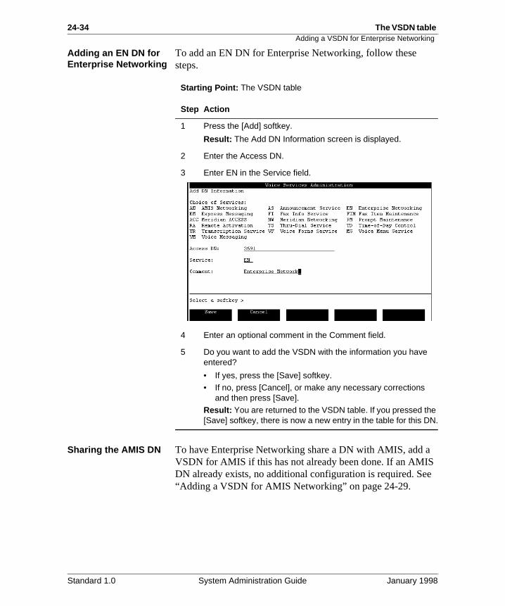
24-34 The VSDN table Adding a VSDN for Enterprise Networking
e
Adding an EN DN for Enterprise Networking
To add an EN DN for Enterprise Networking, follow these steps.
Starting Point: The VSDN table
Sharing the AMIS DN To have Enterprise Networking share a DN with AMIS, add aVSDN for AMIS if this has not already been done. If an AMISDN already exists, no additional configuration is required. Se“Adding a VSDN for AMIS Networking” on page 24-29.
Step Action
1 Press the [Add] softkey.
Result: The Add DN Information screen is displayed.
2 Enter the Access DN.
3 Enter EN in the Service field.
4 Enter an optional comment in the Comment field.
5 Do you want to add the VSDN with the information you have entered?
• If yes, press the [Save] softkey.• If no, press [Cancel], or make any necessary corrections
and then press [Save].
Result: You are returned to the VSDN table. If you pressed the [Save] softkey, there is now a new entry in the table for this DN.
Standard 1.0 System Administration Guide January 1998
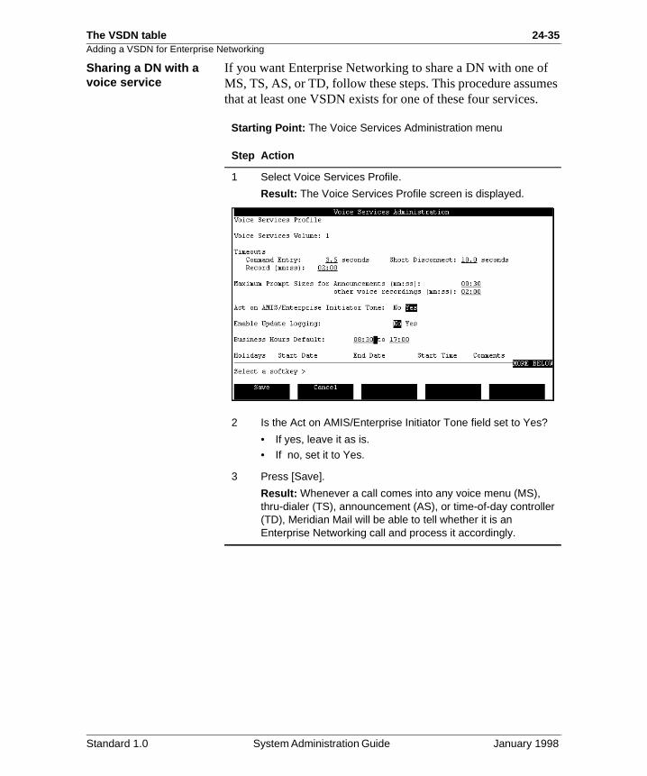
The VSDN table 24-35Adding a VSDN for Enterprise Networking
es
Sharing a DN with a voice service
If you want Enterprise Networking to share a DN with one ofMS, TS, AS, or TD, follow these steps. This procedure assumthat at least one VSDN exists for one of these four services.
Starting Point: The Voice Services Administration menu
Step Action
1 Select Voice Services Profile.
Result: The Voice Services Profile screen is displayed.
2 Is the Act on AMIS/Enterprise Initiator Tone field set to Yes?
• If yes, leave it as is.• If no, set it to Yes.
3 Press [Save].
Result: Whenever a call comes into any voice menu (MS), thru-dialer (TS), announcement (AS), or time-of-day controller (TD), Meridian Mail will be able to tell whether it is an Enterprise Networking call and process it accordingly.
Standard 1.0 System Administration Guide January 1998
24-36 The VSDN table Adding a VSDN for a Meridian ACCESS application
to
a h d.
See
.
Adding a VSDN for a Meridian ACCESS application
Description ACCESS applications include IVR applications and VISIT Messenger.
When to use Create a VSDN for each ACCESS application that you wantmake directly accessible to callers.
The ACCESS class Every ACCESS application has a unique identifier known asclass. This is similar to the concept of an ID. It indicates whicACCESS application you want to run when the VSDN is diale
The Revert DN When adding a VSDN for an ACCESS application, you can specify a Revert DN in your VSDN definition. If an ACCESSapplication goes off-line, calls are transferred to this DN.
Before you begin Access the VSDN table if you are not already at the screen. “Accessing the VSDN table” on page 24-7.
Procedure To add a DN for an ACCESS application, follow these steps
Starting Point: The VSDN table
Step Action
1 Press the [Add] softkey.
Result: The Add DN Information screen is displayed.
2 Enter the Access DN.
Standard 1.0 System Administration Guide January 1998
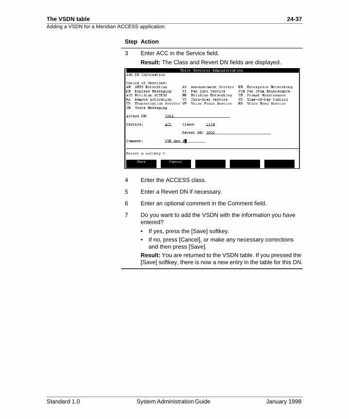
The VSDN table 24-37Adding a VSDN for a Meridian ACCESS application
3 Enter ACC in the Service field.
Result: The Class and Revert DN fields are displayed.
4 Enter the ACCESS class.
5 Enter a Revert DN if necessary.
6 Enter an optional comment in the Comment field.
7 Do you want to add the VSDN with the information you have entered?
• If yes, press the [Save] softkey.
• If no, press [Cancel], or make any necessary corrections and then press [Save].
Result: You are returned to the VSDN table. If you pressed the [Save] softkey, there is now a new entry in the table for this DN.
Step Action
Standard 1.0 System Administration Guide January 1998

24-38 The VSDN table Adding a VSDN for a Meridian ACCESS application
Standard 1.0 System Administration Guide January 1998
The VSDN table 24-39
Section D: Adding voice service and fax service DNs
In this section
Overview 24-40
Adding a VSDN for an announcement 24-41
Adding a VSDN for a thru-dial service 24-43
Adding a VSDN for a voice menu 24-45
Adding a VSDN for a time-of-day controller 24-48
Adding a VSDN for Voice Prompt Maintenance 24-52
Adding a VSDN for Remote Activation 24-54
Adding a VSDN for a voice form 24-56
Adding a VSDN for the Transcription Service 24-58
Adding a VSDN for the Fax Information Service 24-61
Adding a VSDN for the Fax Item Maintenance Service 24-64
Standard 1.0 System Administration Guide January 1998
24-40 The VSDN table Overview
s,
sion
Overview
Introduction When you add a VSDN for any of the following services, youmust assign a session profile to it:
• voice menu
• time-of-day controller
• fax item
• fax item maintenance service
Session profiles There are three predefined session profiles from which to choose. They are based on the channel capability that is required to run the service:
• Basic service
• Full-service voice
• Full-service multimedia
If none of these predefined session profiles meets your needyou can create a custom session profile. Procedures in this section indicate when you need to select or customize a sesprofile.
For more information about session profiles, see the section"Session profiles" on page 24-67.
Standard 1.0 System Administration Guide January 1998
The VSDN table 24-41Adding a VSDN for an announcement
is
ling
See
Adding a VSDN for an announcement
Description An announcement is a voice service that is part of the VoiceMenus feature. An announcement is simply a recording thatplayed to a caller.
When to use Create a VSDN for an announcement if you want users or callers to be able to access the announcement directly by diaa number.
Before you begin Access the VSDN table if you are not already at the screen. “Accessing the VSDN table” on page 24-7.
Procedure To create a VSDN for an announcement, follow these steps.
Starting Point: The VSDN table
Step Action
1 Press the [Add] softkey.
Result: The Add DN Information screen is displayed.
2 Enter the Access DN.
3 Enter AS in the Service field.
Result: The Announcement ID field is displayed.
Standard 1.0 System Administration Guide January 1998
24-42 The VSDN table Adding a VSDN for an announcement
4 Enter the Announcement ID.
Note: If you have not created the announcement yet, you must enter an ID to save the VSDN. Enter an ID and use this ID when creating the announcement.
5 Enter an optional comment in the Comment field.
6 Do you want to add the VSDN with the information you have entered?
• If yes, press the [Save] softkey.• If no, press [Cancel], or make any necessary corrections
and then press [Save].
Result: You are returned to the VSDN table. If you pressed the [Save] softkey, there is now a new entry in the table for this DN.
Step Action
Standard 1.0 System Administration Guide January 1998
The VSDN table 24-43Adding a VSDN for a thru-dial service
s n
o .
See
Adding a VSDN for a thru-dial service
Description A thru-dialer is a voice service that is part of the voice menufeature. Its function is to provide call handling. When a calleraccesses a thru-dialer, he or she is prompted for an extensionumber. The thru-dialer then places the phone call.
When to use Create a VSDN for a thru-dialer if you want users or callers tbe able to access the thru-dialer directly by dialing a number
Before you begin Access the VSDN table if you are not already at the screen. “Accessing the VSDN table” on page 24-7.
Procedure To create a VSDN for a thru-dialer, follow these steps.
Starting Point: The VSDN table
Step Action
1 Press the [Add] softkey.
Result: The Add DN Information screen is displayed.
2 Enter the Access DN.
3 Enter TS in the Service field.
Result: The Thru-Dial ID field is displayed.
Standard 1.0 System Administration Guide January 1998
24-44 The VSDN table Adding a VSDN for a thru-dial service
4 Enter the Thru-Dial ID.
Note: If you have not created the thru-dialer yet, you must enter an ID to save the VSDN. Enter an ID and use this ID when creating the thru-dialer.
5 Enter an optional comment in the Comment field.
6 Do you want to add the VSDN with the information you have entered?
• If yes, press the [Save] softkey.• If no, press [Cancel], or make any necessary corrections
and then press [Save].
Result: You are returned to the VSDN table. If you pressed the [Save] softkey, there is now a new entry in the table for this DN.
Step Action
Standard 1.0 System Administration Guide January 1998
The VSDN table 24-45Adding a VSDN for a voice menu
n
to er.
ch on
Adding a VSDN for a voice menu
Description Voice menus present callers with a list of options from whichthey can make a selection by pressing the appropriate key otheir telephone keypad.
When to use Create a VSDN for a voice menu if you want users or callersbe able to access the voice menu directly by dialing a numb
Choosing the session profile
You must assign a session profile to all voice menus for whiyou add a VSDN. Use this table to decide what kind of sessiprofile you need for the voice menu.
IF the voice menu THEN
invokes one or more of the following only:
• ACCESS applications (such as IVR)
• announcements
• thru-dial services
• voice prompt maintenance
• remote activation
• voice menu commands (such as play prompt, call revert DN, or repeat menu choices)
• other voice menus or time-of-day controllers that invoke the above services only
• select the basic service session profile.
or
• create a custom session profile and set channel capability to Basic.
invokes any of the following:
• voice messaging
• express messaging
• call answering
• fax items using call back delivery mode
• other voice menus or time-of-day controllers that invoke any of the above services
• select the full-service voice session profile. or
• create a custom session profile and set channel capability to Full Voice.
invokes any of the following:
• fax item maintenance
• fax items using same call or caller choice delivery mode
• choose the full-service multimedia session profile. or
• create a custom session profile and set channel capability to Full MultiMedia.
Standard 1.0 System Administration Guide January 1998
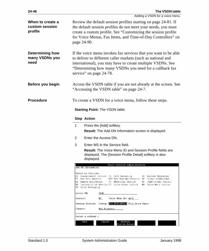
24-46 The VSDN table Adding a VSDN for a voice menu
f st
n
ble
See
When to create a custom session profile
Review the default session profiles starting on page 24-81. Ithe default session profiles do not meet your needs, you mucreate a custom profile. See “Customizing the session profilefor Voice Menus, Fax Items, and Time-of-Day Controllers” opage 24-90.
Determining how many VSDNs you need
If the voice menu invokes fax services that you want to be ato deliver to different caller markets (such as national and international), you may have to create multiple VSDNs. See “Determining how many VSDNs you need for a callback fax service” on page 24-78.
Before you begin Access the VSDN table if you are not already at the screen. “Accessing the VSDN table” on page 24-7.
Procedure To create a VSDN for a voice menu, follow these steps.
Starting Point: The VSDN table
Step Action
1 Press the [Add] softkey.
Result: The Add DN Information screen is displayed.
2 Enter the Access DN.
3 Enter MS in the Service field.
Result: The Voice Menu ID and Session Profile fields are displayed. The [Session Profile Detail] softkey is also displayed.
Standard 1.0 System Administration Guide January 1998
The VSDN table 24-47Adding a VSDN for a voice menu
4 Enter the Voice Menu ID.
Note: If you have not created the voice menu yet, you must enter an ID to save the VSDN. Enter an ID and use this ID when creating the voice menu.
5 Do you need to create a custom session profile?
• If yes, see the section "Session profiles" on page 24-67 and then go to step 9.
• If no, go to step 6.
6 Select one of the predefined session profiles (Basic, Full Voice, or Full MultiMedia).
7 Do you want to view the session profile?
• If yes, press the [Session Profile Detail] softkey.• If no, go to step 9.
8 Review the session profile and press [Return to Previous Form] when you are ready to return to the Add DN Information screen.
9 Enter an optional comment in the Comment field.
10 Do you want to add the VSDN with the information you have entered?
• If yes, press the [Save] softkey.• If no, press [Cancel], or make any necessary corrections
and then press [Save].
Result: You are returned to the VSDN table. If you pressed the [Save] softkey, there is now a new entry in the table for this DN.
Step Action
Standard 1.0 System Administration Guide January 1998
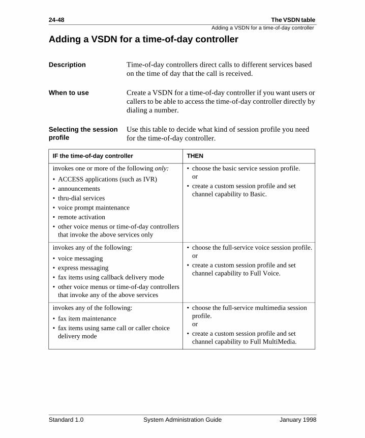
24-48 The VSDN table Adding a VSDN for a time-of-day controller
d
or by
d
Adding a VSDN for a time-of-day controller
Description Time-of-day controllers direct calls to different services baseon the time of day that the call is received.
When to use Create a VSDN for a time-of-day controller if you want users callers to be able to access the time-of-day controller directlydialing a number.
Selecting the session profile
Use this table to decide what kind of session profile you neefor the time-of-day controller.
IF the time-of-day controller THEN
invokes one or more of the following only:
• ACCESS applications (such as IVR)
• announcements
• thru-dial services
• voice prompt maintenance
• remote activation
• other voice menus or time-of-day controllers that invoke the above services only
• choose the basic service session profile. or
• create a custom session profile and set channel capability to Basic.
invokes any of the following:
• voice messaging
• express messaging
• fax items using callback delivery mode
• other voice menus or time-of-day controllers that invoke any of the above services
• choose the full-service voice session profile.or
• create a custom session profile and set channel capability to Full Voice.
invokes any of the following:
• fax item maintenance
• fax items using same call or caller choice delivery mode
• choose the full-service multimedia session profile. or
• create a custom session profile and set channel capability to Full MultiMedia.
Standard 1.0 System Administration Guide January 1998
The VSDN table 24-49Adding a VSDN for a time-of-day controller
f st
n
nt nal ee
See
When to create a custom session profile
Review the default session profiles starting on page 24-81. Ithe default session profiles do not meet your needs, you mucreate a custom profile. See “Customizing the session profilefor Voice Menus, Fax Items, and Time-of-Day Controllers” opage 24-90.
Determining how many VSDNs you need
If the time-of-day controller invokes fax services that you wato be able to deliver to different caller markets (such as natioand international), you may have to create multiple VSDNs. S“Determining how many VSDNs you need for a callback fax service” on page 24-78.
Before you begin Access the VSDN table if you are not already at the screen. “Accessing the VSDN table” on page 24-7.
Standard 1.0 System Administration Guide January 1998
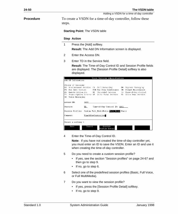
24-50 The VSDN table Adding a VSDN for a time-of-day controller
Procedure To create a VSDN for a time-of-day controller, follow these steps.
Starting Point: The VSDN table
Step Action
1 Press the [Add] softkey.
Result: The Add DN Information screen is displayed.
2 Enter the Access DN.
3 Enter TD in the Service field.
Result: The Time-of-Day Control ID and Session Profile fields are displayed. The [Session Profile Detail] softkey is also displayed.
4 Enter the Time-of-Day Control ID.
Note: If you have not created the time-of-day controller yet, you must enter an ID to save the VSDN. Enter an ID and use it when creating the time-of-day controller.
5 Do you need to create a custom session profile?
• If yes, see the section "Session profiles" on page 24-67 and then go to step 9.
• If no, go to step 6.
6 Select one of the predefined session profiles (Basic, Full Voice, or Full MultiMedia).
7 Do you want to view the session profile?
• If yes, press the [Session Profile Detail] softkey.• If no, go to step 9.
Standard 1.0 System Administration Guide January 1998
The VSDN table 24-51Adding a VSDN for a time-of-day controller
8 Review the session profile and press [Return to Previous Form] when you are ready to return to the Add DN Information screen.
9 Enter an optional comment in the Comment field.
10 Do you want to add the VSDN with the information you have entered?
• If yes, press the [Save] softkey.• If no, press [Cancel], or make any necessary corrections
and then press [Save].
Result: You are returned to the VSDN table. If you pressed the [Save] softkey, there is now a new entry in the table for this DN.
Step Action
Standard 1.0 System Administration Guide January 1998
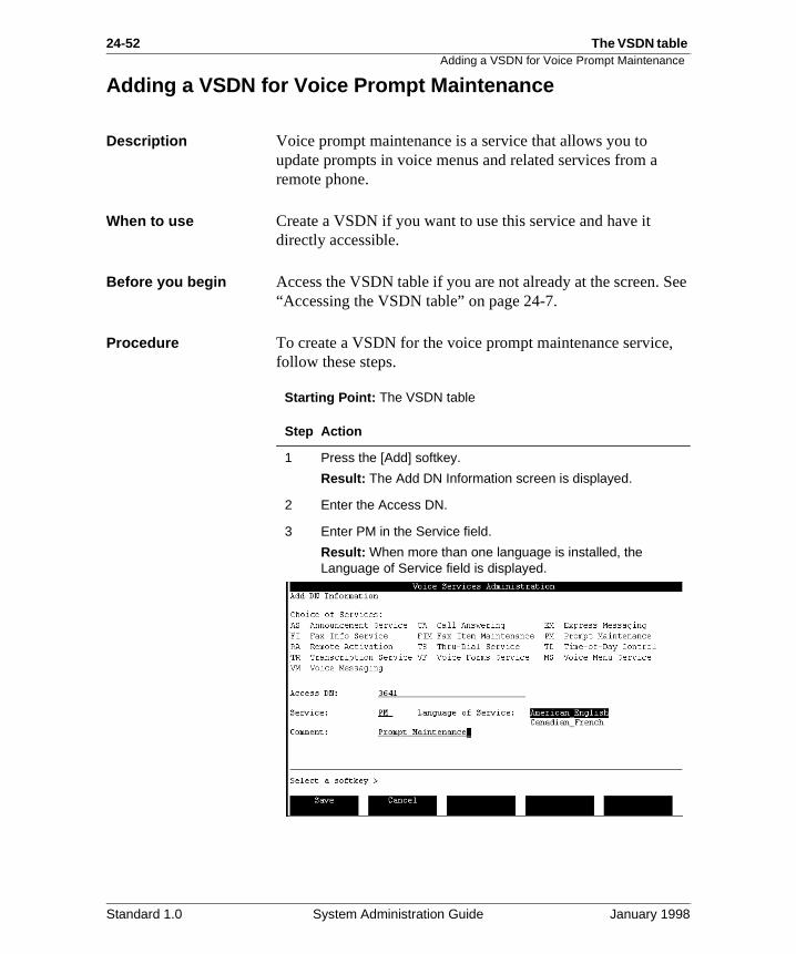
24-52 The VSDN table Adding a VSDN for Voice Prompt Maintenance
See
,
Adding a VSDN for Voice Prompt Maintenance
Description Voice prompt maintenance is a service that allows you to update prompts in voice menus and related services from a remote phone.
When to use Create a VSDN if you want to use this service and have it directly accessible.
Before you begin Access the VSDN table if you are not already at the screen. “Accessing the VSDN table” on page 24-7.
Procedure To create a VSDN for the voice prompt maintenance servicefollow these steps.
Starting Point: The VSDN table
Step Action
1 Press the [Add] softkey.
Result: The Add DN Information screen is displayed.
2 Enter the Access DN.
3 Enter PM in the Service field.
Result: When more than one language is installed, the Language of Service field is displayed.
Standard 1.0 System Administration Guide January 1998
The VSDN table 24-53Adding a VSDN for Voice Prompt Maintenance
4 If more than one language is installed, select the language in which you want prompt maintenance prompts to be played.
5 Do you want to add the VSDN with the information you have entered?
• If yes, press the [Save] softkey.• If no, press [Cancel], or make any necessary corrections
and then press [Save].
Result: You are returned to the VSDN table. If you pressed the [Save] softkey, there is now a new entry in the table for this DN.
Step Action
Standard 1.0 System Administration Guide January 1998
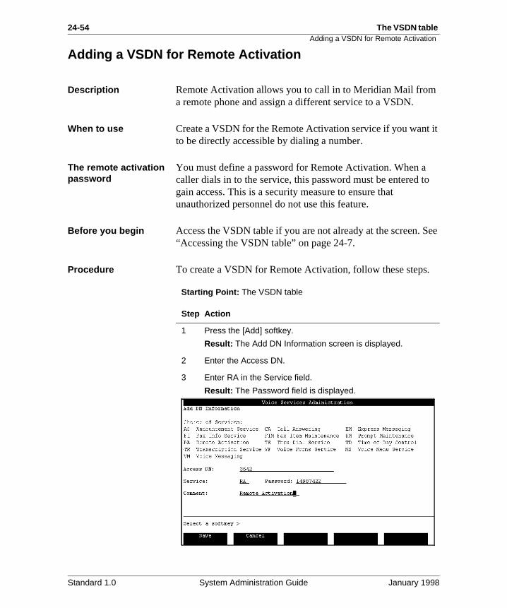
24-54 The VSDN table Adding a VSDN for Remote Activation
it
to
See
.
Adding a VSDN for Remote Activation
Description Remote Activation allows you to call in to Meridian Mail froma remote phone and assign a different service to a VSDN.
When to use Create a VSDN for the Remote Activation service if you wantto be directly accessible by dialing a number.
The remote activation password
You must define a password for Remote Activation. When acaller dials in to the service, this password must be entered gain access. This is a security measure to ensure that unauthorized personnel do not use this feature.
Before you begin Access the VSDN table if you are not already at the screen. “Accessing the VSDN table” on page 24-7.
Procedure To create a VSDN for Remote Activation, follow these steps
Starting Point: The VSDN table
Step Action
1 Press the [Add] softkey.
Result: The Add DN Information screen is displayed.
2 Enter the Access DN.
3 Enter RA in the Service field.
Result: The Password field is displayed.
Standard 1.0 System Administration Guide January 1998
The VSDN table 24-55Adding a VSDN for Remote Activation
4 Enter a password.
Note: This password must be defined. If no password is entered, remote activation is not enabled.
5 Do you want to add the VSDN with the information you have entered?
• If yes, press the [Save] softkey.
• If no, press [Cancel], or make any necessary corrections and then press [Save].
Result: You are returned to the VSDN table. If you pressed the [Save] softkey, there is now a new entry in the table for this DN.
Step Action
Standard 1.0 System Administration Guide January 1998
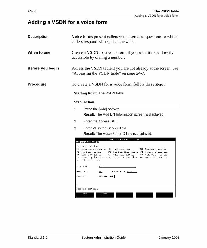
24-56 The VSDN table Adding a VSDN for a voice form
ch
See
Adding a VSDN for a voice form
Description Voice forms present callers with a series of questions to whicallers respond with spoken answers.
When to use Create a VSDN for a voice form if you want it to be directly accessible by dialing a number.
Before you begin Access the VSDN table if you are not already at the screen. “Accessing the VSDN table” on page 24-7.
Procedure To create a VSDN for a voice form, follow these steps.
Starting Point: The VSDN table
Step Action
1 Press the [Add] softkey.
Result: The Add DN Information screen is displayed.
2 Enter the Access DN.
3 Enter VF in the Service field.
Result: The Voice Form ID field is displayed.
Standard 1.0 System Administration Guide January 1998
The VSDN table 24-57Adding a VSDN for a voice form
4 Enter the voice form ID.
Note: If you have not created the voice form yet, you must enter an ID to save the VSDN. Enter an ID and use this ID when creating the voice form.
5 Do you want to add the VSDN with the information you have entered?
• If yes, press the [Save] softkey.• If no, press [Cancel], or make any necessary corrections
and then press [Save].
Result: You are returned to the VSDN table. If you pressed the [Save] softkey, there is now a new entry in the table for this DN.
Step Action
Standard 1.0 System Administration Guide January 1998
24-58 The VSDN table Adding a VSDN for the Transcription Service
. It
:
e
in
e,
g
his
ng
he
le
e re,
Adding a VSDN for the Transcription Service
Description The Transcription Service is part of the Voice Forms featureallows a transcriber to log in to a voice form, listen to the recorded responses, and transcribe them.
When to use Create a VSDN for the Transcription Service if you want it tobe directly accessible by dialing a number.
Types of transcription services
You can create two different types of Transcription Services
• a service that retrieves any voice form as specified by thtranscriber
• a service that retrieves a specific voice form as defined the Add DN Information screen
Application 1: General transcription service
In this application, when the transcriber logs on to the serviche or she is prompted for the ID of the voice form to be transcribed. This allows the transcriber to access any existinvoice form.
If you want to create only one Transcription Service, create tkind and leave it up to the transcriber to decide which voice form to retrieve.
For this application, do not enter a Voice Form ID when addithe VSDN.
Application 2: Voice-form specific
In this application, a particular voice form is associated with tVSDN. Whenever the VSDN is dialed, that voice form is automatically retrieved for transcription. You can have multiptranscription VSDNs so that a number of voice forms can becalled up directly depending on the VSDN that was dialed.
You may want to do this if you have just implemented a voicform to which you expect a lot of responses, and you, therefowant to have it transcribed frequently.
For this application, enter a Voice Form ID when adding the VSDN.
Standard 1.0 System Administration Guide January 1998
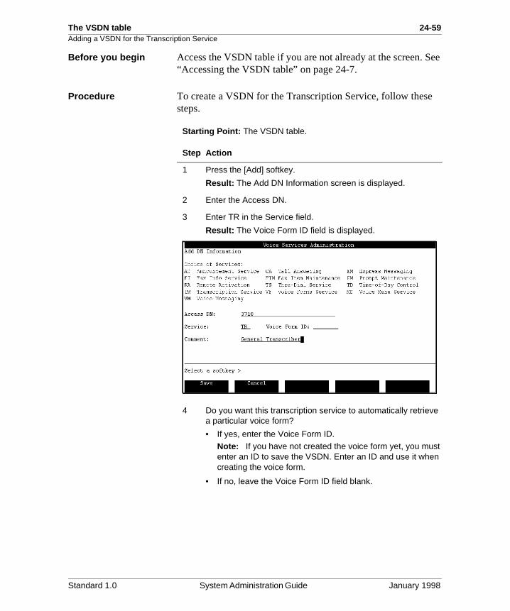
The VSDN table 24-59Adding a VSDN for the Transcription Service
See
Before you begin Access the VSDN table if you are not already at the screen. “Accessing the VSDN table” on page 24-7.
Procedure To create a VSDN for the Transcription Service, follow thesesteps.
Starting Point: The VSDN table.
Step Action
1 Press the [Add] softkey.
Result: The Add DN Information screen is displayed.
2 Enter the Access DN.
3 Enter TR in the Service field.
Result: The Voice Form ID field is displayed.
4 Do you want this transcription service to automatically retrieve a particular voice form?
• If yes, enter the Voice Form ID.
Note: If you have not created the voice form yet, you must enter an ID to save the VSDN. Enter an ID and use it when creating the voice form.
• If no, leave the Voice Form ID field blank.
Standard 1.0 System Administration Guide January 1998
24-60 The VSDN table Adding a VSDN for the Transcription Service
5 Do you want to add the VSDN with the information you have entered?
• If yes, press the [Save] softkey.• If no, press [Cancel], or make any necessary corrections
and then press [Save].
Result: You are returned to the VSDN table. If you pressed the [Save] softkey, there is now a new entry in the table for this DN.
Step Action
Standard 1.0 System Administration Guide January 1998
The VSDN table 24-61Adding a VSDN for the Fax Information Service
on
be
fax
do ,
to
ia
Adding a VSDN for the Fax Information Service
Description The Fax Information Service is part of the Fax on Demand feature. It is used to create fax items that are sent to callers request.
When to use Create a VSDN for a fax item if you want users or callers to able to access it directly by dialing a number.
Selecting the session profile
Use this table to decide which session profile you need for a item.
When to create a custom session profile
Review the configurations of the default full-service voice session profile on page 24-83 and the full-service multimediasession profile on page 24-86. If the default session profiles not meet your needs, you must create a custom profile. See“Customizing the session profile for Voice Menus, Fax Itemsand Time-of-Day Controllers” on page 24-90.
Determining how many VSDNs you need
If you want this fax item to be delivered to different caller markets (such as national and international), you may have create multiple VSDNs. See “Determining how many VSDNsyou need for a callback fax service” on page 24-78.
If the fax delivery mode THEN
is callback • choose the full-service voice session profile. or
• create a custom session profile andset the channel capability to Full Voice.
is caller choice or same call • choose the full-service multimedsession profile. or
• create a custom session profile andset the channel capability to Full MultiMedia.
Standard 1.0 System Administration Guide January 1998
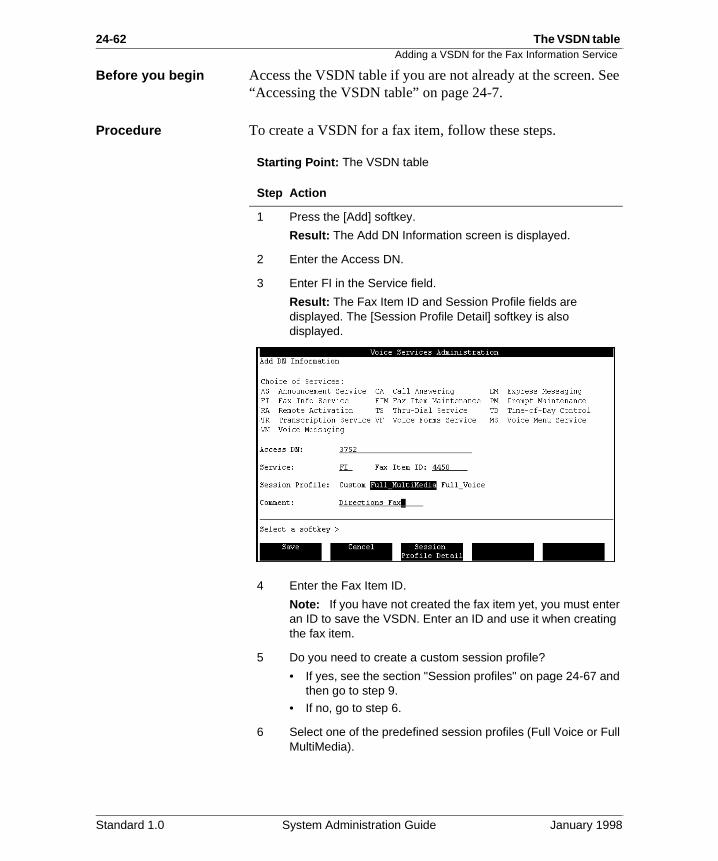
24-62 The VSDN table Adding a VSDN for the Fax Information Service
See
Before you begin Access the VSDN table if you are not already at the screen. “Accessing the VSDN table” on page 24-7.Procedure To create a VSDN for a fax item, follow these steps.
Starting Point: The VSDN table
Step Action
1 Press the [Add] softkey.
Result: The Add DN Information screen is displayed.
2 Enter the Access DN.
3 Enter FI in the Service field.
Result: The Fax Item ID and Session Profile fields are displayed. The [Session Profile Detail] softkey is also displayed.
4 Enter the Fax Item ID.
Note: If you have not created the fax item yet, you must enter an ID to save the VSDN. Enter an ID and use it when creating the fax item.
5 Do you need to create a custom session profile?
• If yes, see the section "Session profiles" on page 24-67 and then go to step 9.
• If no, go to step 6.
6 Select one of the predefined session profiles (Full Voice or Full MultiMedia).
Standard 1.0 System Administration Guide January 1998
The VSDN table 24-63Adding a VSDN for the Fax Information Service
7 Do you want to view the session profile?
• If yes, press the [Session Profile Detail] softkey.• If no, go to step 9.
8 Review the session profile and press [Return to Previous Form] when you are ready to return to the Add DN Information screen.
9 Enter an optional comment in the Comment field.
10 Do you want to add the VSDN with the information you have entered?
• If yes, press the [Save] softkey.
• If no, press [Cancel], or make any necessary corrections and then press [Save].
Result: You are returned to the VSDN table. If you pressed the [Save] softkey, there is now a new entry in the table for this DN.
Step Action
Standard 1.0 System Administration Guide January 1998
24-64 The VSDN table Adding a VSDN for the Fax Item Maintenance Service
and
ce
ia oes ce
See
w
Adding a VSDN for the Fax Item Maintenance Service
Description The Fax Item Maintenance service is part of the Fax on Demfeature. It is used to remotely maintain the content and characteristics of fax items using a telephone set. This servialso allows you to verify changed content by sending a verification fax to a specified fax number.
When to use Create a VSDN for the Fax Item Maintenance service if you want to be able to access it directly by dialing a number.
Selecting the session profile
You must use the full-service multimedia session profile or create a custom profile with channel capability set to Full Multimedia.
Do you need a custom session profile?
Review the configuration for the default full-service multimedsession profile on page 24-86. If the default session profile dnot meet your needs, you must create a custom profile. See“Customizing the session profile for the Fax Item MaintenanService” on page 24-109.
Before you begin Access the VSDN table if you are not already at the screen. “Accessing the VSDN table” on page 24-7.
Procedure To create a VSDN for the Fax Item Maintenance service, follothese steps.
Starting Point: The VSDN table
Step Action
1 Press the [Add] softkey.
Result: The Add DN Information screen is displayed.
2 Enter the Access DN.
Standard 1.0 System Administration Guide January 1998
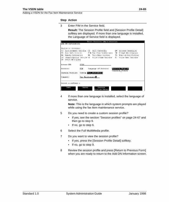
The VSDN table 24-65Adding a VSDN for the Fax Item Maintenance Service
3 Enter FIM in the Service field.
Result: The Session Profile field and [Session Profile Detail] softkey are displayed. If more than one language is installed, the Language of Service field is displayed.
4 If more than one language is installed, select the language of service.
Note: This is the language in which system prompts are played while using the fax item maintenance service.
5 Do you need to create a custom session profile?
• If yes, see the section "Session profiles" on page 24-67 and then go to step 9.
• If no, go to step 6.
6 Select the Full MultiMedia profile.
7 Do you want to view the session profile?
• If yes, press the [Session Profile Detail] softkey.• If no, go to step 9.
8 Review the session profile and press [Return to Previous Form] when you are ready to return to the Add DN Information screen.
Step Action
Standard 1.0 System Administration Guide January 1998
24-66 The VSDN table Adding a VSDN for the Fax Item Maintenance Service
9 Enter an optional comment in the Comment field.
10 Do you want to add the VSDN with the information you have entered?
• If yes, press the [Save] softkey.• If no, press [Cancel], or make any necessary corrections
and then press [Save].
Result: You are returned to the VSDN table. If you pressed the [Save] softkey, there is now a new entry in the table for this DN.
Step Action
Standard 1.0 System Administration Guide January 1998
Chapter 24
The VSDN table 24-67Section E: Session profiles
In this section
What is a session profile? 24-68
How session profiles work when multiple services are invoked by one VSDN
24-70
How Meridian Mail 9/10 session profiles are converted to Meridian Mail 12 session profiles
24-72
Fax callback number formats 24-74
Determining how many VSDNs you need for a callback fax service
24-78
The basic service session profile 24-81
The full-service voice session profile 24-83
The full-service multimedia session profile 24-86
Customizing the session profile for Voice Menus, Fax Items, and Time-of-Day Controllers
24-90
Specifying the channel capability, session time limit, and maximum number of invalid selections
24-92
Specifying fax service options 24-96
Specifying callback delivery options 24-102
Creating a custom cover sheet 24-107
Customizing the session profile for the Fax Item Maintenance Service
24-109
Standard 1.0 System Administration Guide January 1998
24-68 The VSDN table
f
rs)
if it if a
What is a session profile?
What is a session profile?
Description A session profile is a set of operational characteristics that determines how the following features work:
• Voice Menus
• Time-of-Day Controllers
• the Fax Information Service (Fax Items)
• the Fax Item Maintenance Service
A session profile is required when you add a VSDN for any othese services.
Example A session profile for a Voice Menu that invokes Fax on Demand services controls the following aspects (among otheof Voice Menu operation:
• the maximum session length
• the maximum number of invalid menu selections
• the maximum number of faxes that a caller can select
• how fax transmission errors are handled
When session profiles are required
The session profile is selected or defined when you add the VSDN. You can either
• select a predefined session profile
• create a custom session profile
You cannot create a session profile for one of these servicesdoes not have a VSDN. Session profiles are necessary onlyVSDN is necessary.
Standard 1.0 System Administration Guide January 1998
The VSDN table 24-69What is a session profile?
The ed.
any ts
ice me
Three predefined profiles
There are three predefined session profiles to choose from. names of the profiles indicate the type of ports that will be us
Custom session profiles
The three predefined session profiles cannot be modified in way. If none of the three preconfigured session profiles meeyour requirements for a particular service, you must create acustom session profile.
A session profile is customized for only one service (the servfor which you are adding a VSDN). You cannot share the sacustom session profile among a number of services.
Profile Described on page
Basic service session profile 24-81
Full-service voice session profile 24-83
Full-service multimedia session profile 24-86
Standard 1.0 System Administration Guide January 1998
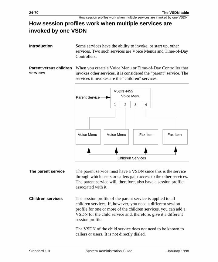
24-70 The VSDN table
ay
at he
ce ces.
a
How session profiles work when multiple services are invoked by one VSDN
How session profiles work when multiple services are invoked by one VSDN
Introduction Some services have the ability to invoke, or start up, other services. Two such services are Voice Menus and Time-of-DControllers.
Parent versus children services
When you create a Voice Menu or Time-of-Day Controller thinvokes other services, it is considered the “parent” service. Tservices it invokes are the “children” services.
The parent service The parent service must have a VSDN since this is the servithrough which users or callers gain access to the other serviThe parent service will, therefore, also have a session profileassociated with it.
Children services The session profile of the parent service is applied to all children services. If, however, you need a different session profile for one or more of the children services, you can add VSDN for the child service and, therefore, give it a different session profile.
The VSDN of the child service does not need to be known tocallers or users. It is not directly dialed.
Voice Menu
1 2 3 4
Voice Menu Voice Menu Fax Item Fax Item
Parent Service
Children Services
VSDN 4455
Standard 1.0 System Administration Guide January 1998
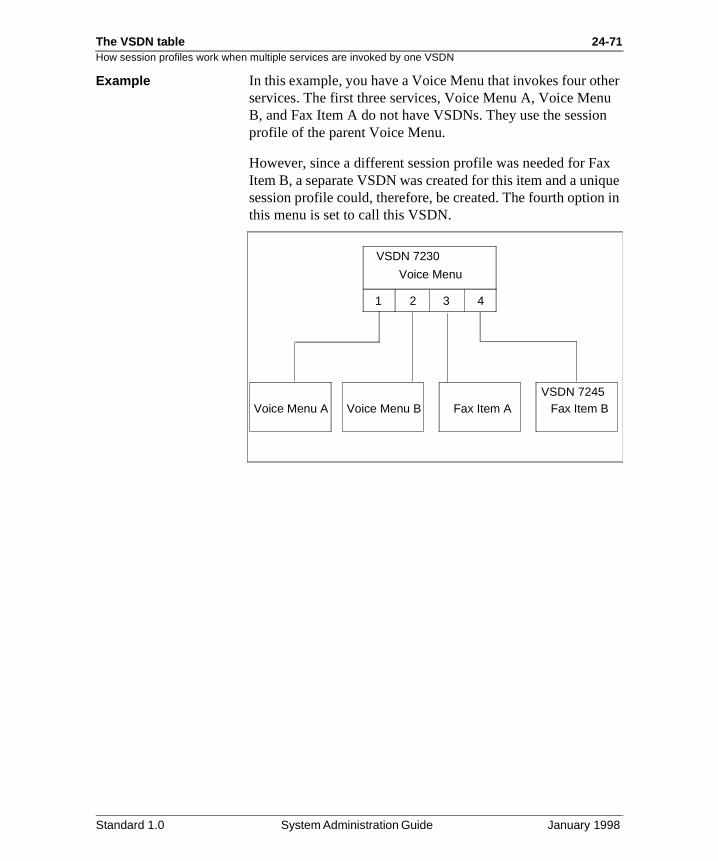
The VSDN table 24-71How session profiles work when multiple services are invoked by one VSDN
er u n
x que in
Example In this example, you have a Voice Menu that invokes four othservices. The first three services, Voice Menu A, Voice MenB, and Fax Item A do not have VSDNs. They use the sessioprofile of the parent Voice Menu.
However, since a different session profile was needed for FaItem B, a separate VSDN was created for this item and a unisession profile could, therefore, be created. The fourth optionthis menu is set to call this VSDN.
Voice Menu
1 2 3 4
Voice Menu A Voice Menu B Fax Item A Fax Item B
VSDN 7230
VSDN 7245
Standard 1.0 System Administration Guide January 1998
24-72 The VSDN table
ld of
et
l.
How Meridian Mail 9/10 session profiles are converted to Meridian Mail 12 session profiles
How Meridian Mail 9/10 session profiles are converted to Meridian Mail 12 session profiles
Introduction The following three fields that were in Meridian Mail 9 and Meridian Mail 10 session profiles have been replaced by onefield, Treat Call Back Number As, in Meridian Mail 12:
• Call Back Number Area Code Translation
• Call Back International DDD
• IDDD Prefix
Description of changes
Call Back Number Area Code TranslationThis field could be set to North American and None. This fieno longer applies. Due to enhancements, dialing translationsnumbers outside North America are now fully supported.
Call Back International DDDThis field was used to define whether international call back delivery was required, optional, or not allowed. This functionality is directly replaced by the new field.
IDDD PrefixThis field was used only if Call Back International DDD was sto optional. It allowed callers to indicate whether they wantedcall back delivery to an international location or a national location relative to the Meridian Mail system. As of Meridian Mail 11, a service is set up either as National or InternationaThere is, therefore, no longer a need for this field.
Standard 1.0 System Administration Guide January 1998
The VSDN table 24-73How Meridian Mail 9/10 session profiles are converted to Meridian Mail 12 session profiles
n s
ed
the
in
ive n
sh
her or
How profiles were converted
When you converted to Meridian Mail 12, any existing sessioprofiles were automatically converted. The only field that waused in the conversion was the Call Back International DDDfield.
This table shows how the old session profile field was mappto the new field.
Optional Call Back International DDD
If you had any session profiles in which the Call Back International DDD field was set to Optional, callers who dial that VSDN are now prompted to enter call back numbers in international format (country code + area/city code + fax number). They do not have the option of entering a number the national format (area/city code + fax number).
OptionsYou can leave these services as is. However, if you want to gcallers the opportunity to enter either a national number or ainternational number, you can do one of the following.
• Set up a “National” VSDN for the same service and publithis number.
• Create a Voice Menu as a front end to the service that allows callers to select national or international.
This solution means that you do not have to publish anotnumber. See “Determining how many VSDNs you need fa callback fax service” on page 24-78.
WHEN the Call Back International DDD field was
THEN the Treat Call Back Number As field was set to
Required International.
Optional International.
Not Allowed National.
Standard 1.0 System Administration Guide January 1998
24-74 The VSDN table
te
the es
d be
in
ler
ler
Fax callback number formats
Fax callback number formats
Introduction Session profiles for fax services or services that invoke fax services must specify the fax delivery method. When the faxdelivery method is call back, the fax is delivered on a separacall. Callers are prompted to enter a call back number duringsession. When the session is terminated, Meridian Mail phonthe callback number in order to deliver the fax.
When the delivery method is call back or caller choice (in which case the caller might choose call back), the callback number format must be specified.
Description: callback number formats
When a caller enters a callback number, it must be translateinto a number that Meridian Mail can dial so that the fax can delivered.
This means that callers must enter callback numbers in certaformats depending on where they are located relative to the Meridian Mail system.
Example Your Meridian Mail system is located in California.
Caller is located in WashingtonSince the caller’s country code is the same as yours, the calneeds to enter the callback number in the following format:
area/city code + fax phone number
Caller is located in FranceSince the caller’s country code is different from yours, the calmust enter the callback number in the following format:
country code + area/city code + fax phone number
Caller is an employee on your ESN networkAn employee that is on your ESN network should specify theESN number of the receiving fax machine in the format:
ESN prefix + fax phone extension
Standard 1.0 System Administration Guide January 1998
The VSDN table 24-75Fax callback number formats
is on
y
ity
.
.
ea
Callback number treatment
The format in which callers must enter their callback numberspecified in the Treat Call Back Number As field in the SessiProfile. There are four callback number treatment options:
• National
• International
• Dial as Entered
• ESN2
National PurposeThis option is for services aimed at callers within your countrcode.
Both local and long distance callers need to enter the area/ccode.
The promptCallers hear the following prompt when this option is chosen
“Please enter the fax number, including area or city code, followed by number sign.”
International PurposeThis option is for services aimed at international callers that have country codes different from yours.
Local and long distance callers within your country code canuse this type of service. However, they need to know their country code. The number cannot be processed without the country code.
The promptCallers hear the following prompt when this option is chosen
“Please enter the fax number, including country code and aror city code, followed by number sign.”
Standard 1.0 System Administration Guide January 1998
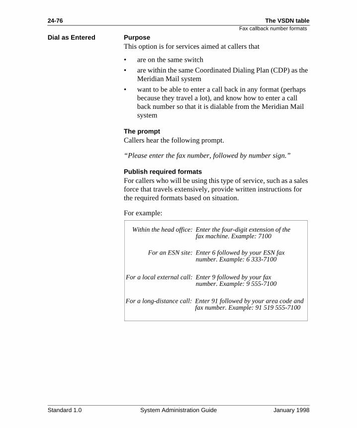
24-76 The VSDN table
he
ps
les
Fax callback number formats
Dial as Entered PurposeThis option is for services aimed at callers that
• are on the same switch
• are within the same Coordinated Dialing Plan (CDP) as tMeridian Mail system
• want to be able to enter a call back in any format (perhabecause they travel a lot), and know how to enter a call back number so that it is dialable from the Meridian Mailsystem
The promptCallers hear the following prompt.
“Please enter the fax number, followed by number sign.”
Publish required formatsFor callers who will be using this type of service, such as a saforce that travels extensively, provide written instructions forthe required formats based on situation.
For example:
Within the head office:
For an ESN site:
For a local external call:
For a long-distance call:
Enter the four-digit extension of thefax machine. Example: 7100
Enter 6 followed by your ESN faxnumber. Example: 6 333-7100
Enter 9 followed by your faxnumber. Example: 9 555-7100
Enter 91 followed by your area code andfax number. Example: 91 519 555-7100
Standard 1.0 System Administration Guide January 1998
The VSDN table 24-77Fax callback number formats
.
y
it
ck
ESN PurposeThis option is for callers (employees) who are on your ESN network.
The promptCallers hear the following prompt when this option is chosen
“Please enter the ESN number of the fax machine followed bnumber sign.”
Translation of callback numbers
Once a callback number is entered, Meridian Mail translatesinto a dialable number. All callback formats, except Dial As Entered, require translation.
The way in which Meridian Mail should translate each callbaformat is defined in translation tables. This is described in Chapter 17, “Dialing translations”.
Standard 1.0 System Administration Guide January 1998
24-78 The VSDN table
er ck
ax
at.
e
cify er
ce
e
e
Determining how many VSDNs you need for a callback fax service
Determining how many VSDNs you need for a callback fax service
Limitation When the Fax Delivery Option field is set to Call Back or CallChoice, you can choose only one of the four types of call batreatments (national, international, dial as entered, or ESN).
Consequence This means that if you want to be able to deliver the same FItem to more than one of the following — national numbers, international numbers, ESN numbers, or any number — youmust choose one of the following strategies:
• Create separate VSDNs for each required call back form
• Create a Voice Menu as a front end.
• Create only one VSDN.
Option 1: separate VSDNs
Set up separate VSDNs for each caller market, with corresponding marketing materials that instruct callers to usthe number that is appropriate for them (depending on their location).
Option 2: Voice Menu
Create a Voice Menu as a front end that allows callers to spewhere their fax machine is located and how they need to entthe call back number.
You still need to create multiple VSDNs as described in the example on page 24-79. However, only the VSDN of the VoiMenu needs to be published to callers.
Option 3: a single VSDN
Create a single VSDN for all callers; that is, set up for international call back. Callers are always prompted to includtheir country code as part of the fax number, even if they arewithin the same country code.
This is the least effective solution since many people who arunfamiliar with international dialing may not know their own country code.
Standard 1.0 System Administration Guide January 1998
The VSDN table 24-79Determining how many VSDNs you need for a callback fax service
t
s
on
s
h
nu the
Example: creating a Voice Menu as a front end
Your company is located in Boston. You have a new producbulletin that you want to make available to your North American customers. However, you also have a strong European customer base, so you also want to make this faxbulletin available to your European customers. You want to create only one set of marketing materials and publish one number for both caller markets.
SetupTo set up this service, you must do the following.
1. Create a Fax Item.
For example, Fax 1.
2. Add a VSDN (4110) for Fax 1.
In the session profile, set the Treat Call Back Number Afield to International.
Callers do not have to know this VSDN.
3. Create the Voice Menu.
- Make menu choice 1 invoke Fax Item 1.
- Make menu choice 2 call (CL) the VSDN 4110.
- Record a menu choices prompt that instructs callers what to do.“If your fax machine is in North America, press 1. If your fax machine is in any other country, press 2.”
4. Add a VSDN for the Voice Menu (4009).
In the session profile, set the Treat Call Back Number Afield to National.
The VSDN of this Voice Menu is the number you publisto callers.
ResultWhen a caller presses 1, the session profile for the Voice Meis used. The caller is prompted to enter an area/city code andfax number.
Standard 1.0 System Administration Guide January 1998
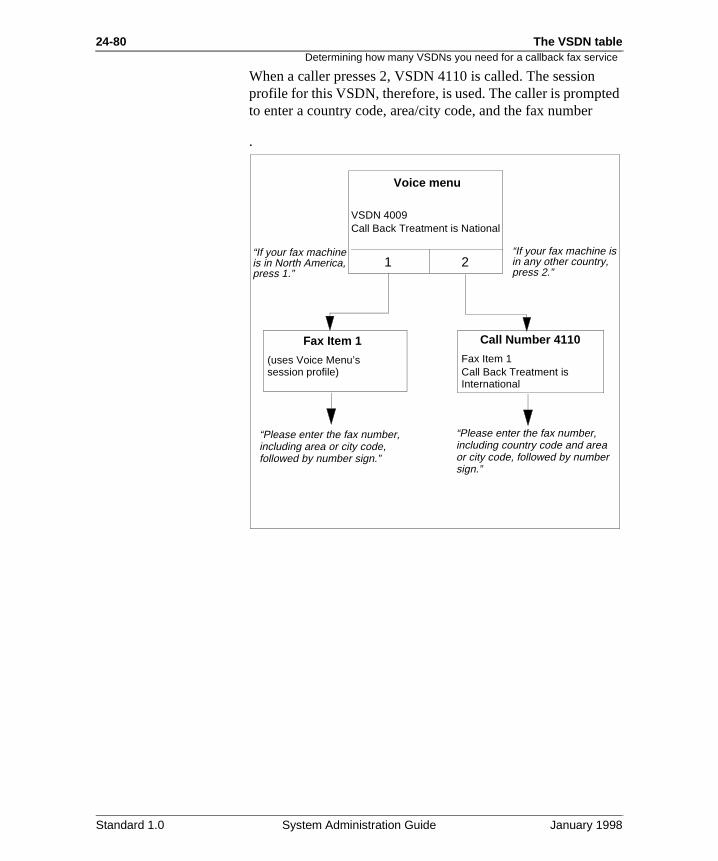
24-80 The VSDN table
ed
Determining how many VSDNs you need for a callback fax service
When a caller presses 2, VSDN 4110 is called. The sessionprofile for this VSDN, therefore, is used. The caller is promptto enter a country code, area/city code, and the fax number
.
Voice menu
1 2
Fax Item 1 Call Number 4110
Fax Item 1Call Back Treatment isInternational
(uses Voice Menu’ssession profile)
Call Back Treatment is NationalVSDN 4009
“Please enter the fax number,including area or city code,followed by number sign.”
“Please enter the fax number,including country code and area or city code, followed by number sign.”
“If your fax machine is in North America,press 1.”
“If your fax machine is in any other country,press 2.”
Standard 1.0 System Administration Guide January 1998
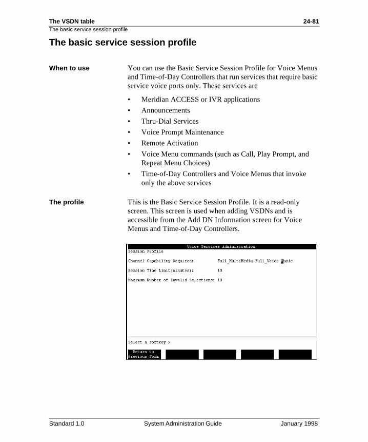
The VSDN table 24-81The basic service session profile
us sic
The basic service session profile
When to use You can use the Basic Service Session Profile for Voice Menand Time-of-Day Controllers that run services that require baservice voice ports only. These services are
• Meridian ACCESS or IVR applications
• Announcements
• Thru-Dial Services
• Voice Prompt Maintenance
• Remote Activation
• Voice Menu commands (such as Call, Play Prompt, andRepeat Menu Choices)
• Time-of-Day Controllers and Voice Menus that invoke only the above services
The profile This is the Basic Service Session Profile. It is a read-only screen. This screen is used when adding VSDNs and is accessible from the Add DN Information screen for Voice Menus and Time-of-Day Controllers.
Standard 1.0 System Administration Guide January 1998
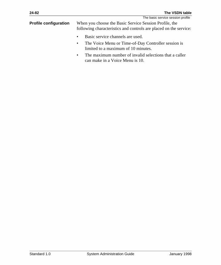
24-82 The VSDN table
ice:
The basic service session profile
Profile configuration When you choose the Basic Service Session Profile, the following characteristics and controls are placed on the serv
• Basic service channels are used.
• The Voice Menu or Time-of-Day Controller session is limited to a maximum of 10 minutes.
• The maximum number of invalid selections that a caller can make in a Voice Menu is 10.
Standard 1.0 System Administration Guide January 1998
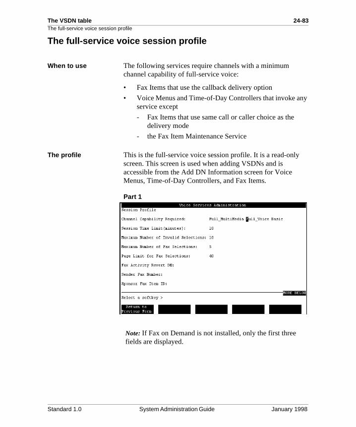
The VSDN table 24-83The full-service voice session profile
y
The full-service voice session profile
When to use The following services require channels with a minimum channel capability of full-service voice:
• Fax Items that use the callback delivery option
• Voice Menus and Time-of-Day Controllers that invoke anservice except
- Fax Items that use same call or caller choice as the delivery mode
- the Fax Item Maintenance Service
The profile This is the full-service voice session profile. It is a read-only screen. This screen is used when adding VSDNs and is accessible from the Add DN Information screen for Voice Menus, Time-of-Day Controllers, and Fax Items.
Part 1
Note: If Fax on Demand is not installed, only the first three fields are displayed.
Standard 1.0 System Administration Guide January 1998
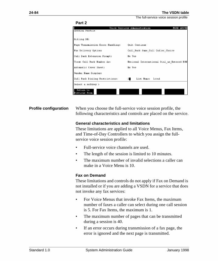
24-84 The VSDN table
ice.
is es
ion
The full-service voice session profile
Part 2
Profile configuration When you choose the full-service voice session profile, the following characteristics and controls are placed on the serv
General characteristics and limitationsThese limitations are applied to all Voice Menus, Fax Items,and Time-of-Day Controllers to which you assign the full-service voice session profile:
• Full-service voice channels are used.
• The length of the session is limited to 10 minutes.
• The maximum number of invalid selections a caller can make in a Voice Menu is 10.
Fax on DemandThese limitations and controls do not apply if Fax on Demandnot installed or if you are adding a VSDN for a service that donot invoke any fax services:
• For Voice Menus that invoke Fax Items, the maximum number of faxes a caller can select during one call sessis 5. For Fax Items, the maximum is 1.
• The maximum number of pages that can be transmittedduring a session is 40.
• If an error occurs during transmission of a fax page, the error is ignored and the next page is transmitted.
Standard 1.0 System Administration Guide January 1998
The VSDN table 24-85The full-service voice session profile
rs re
as
n
the
is be
• The fax delivery option is call back. This means that calledo not have to make the call on a fax phone since they aprompted for a callback number. After the session is terminated, the fax is delivered to the specified number long as it is not restricted.
• Callers are prompted for an extension number in additioto the callback number. This number is printed on the automatic cover sheet so that the fax can be delivered toright person.
• The callback number is treated as a national number. Thmeans that the callback number entered by callers mustwithin the same country code as your system.
• A system-generated cover sheet is attached to the fax.
• Restriction/Permission List 2 (named Local by default) isapplied to call back delivery.
Standard 1.0 System Administration Guide January 1998
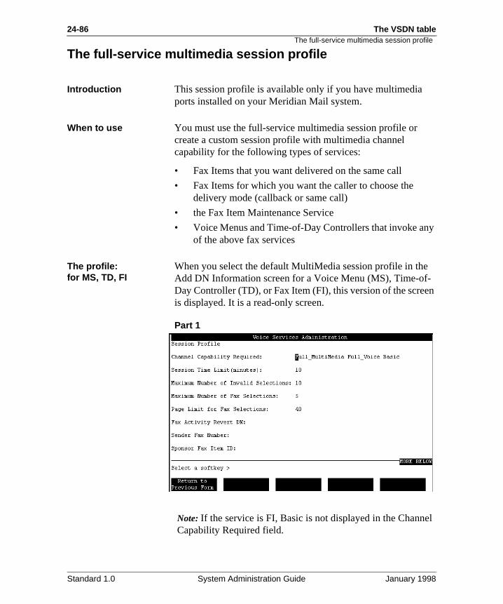
24-86 The VSDN table
y
n
el
The full-service multimedia session profile
The full-service multimedia session profile
Introduction This session profile is available only if you have multimedia ports installed on your Meridian Mail system.
When to use You must use the full-service multimedia session profile or create a custom session profile with multimedia channel capability for the following types of services:
• Fax Items that you want delivered on the same call
• Fax Items for which you want the caller to choose the delivery mode (callback or same call)
• the Fax Item Maintenance Service
• Voice Menus and Time-of-Day Controllers that invoke anof the above fax services
The profile: for MS, TD, FI
When you select the default MultiMedia session profile in theAdd DN Information screen for a Voice Menu (MS), Time-of-Day Controller (TD), or Fax Item (FI), this version of the screeis displayed. It is a read-only screen.
Part 1
Note: If the service is FI, Basic is not displayed in the ChannCapability Required field.
Standard 1.0 System Administration Guide January 1998
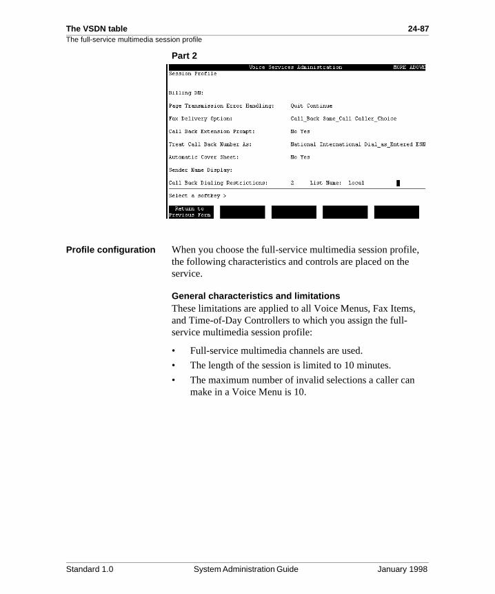
The VSDN table 24-87The full-service multimedia session profile
,
Part 2
Profile configuration When you choose the full-service multimedia session profilethe following characteristics and controls are placed on the service.
General characteristics and limitationsThese limitations are applied to all Voice Menus, Fax Items,and Time-of-Day Controllers to which you assign the full-service multimedia session profile:
• Full-service multimedia channels are used.
• The length of the session is limited to 10 minutes.
• The maximum number of invalid selections a caller can make in a Voice Menu is 10.
Standard 1.0 System Administration Guide January 1998
24-88 The VSDN table
n
ion
r to e
ic
is
me
The full-service multimedia session profile
Fax on DemandThese following limitations and controls do not apply if Fax oDemand is not installed or if you are adding a VSDN for a service that does not invoke any fax services:
• For Voice Menus that invoke Fax Items, the maximum number of faxes a caller can select during one call sessis 5. For Fax Items, the maximum is 1.
• The maximum number of pages that can be transmittedduring a session is 40.
• If an error occurs during transmission of a fax page, the error is ignored and the next page is transmitted.
• Fax delivery is set to caller choice. This means the callecan request to have the fax delivered on the same call (the fax phone on which the caller placed the call) or canspecify the callback number of the fax phone to which hor she wants the fax delivered.
• If the caller chooses callback delivery, the caller is prompted for an extension number in addition to the callback number. This number is printed on the automatcover sheet so that the fax can be delivered to the right person.
• The callback number is treated as a national number. Thmeans that if a caller chooses callback delivery, the callback number entered by callers must be within the sacountry code as your system.
• A system-generated cover sheet is attached to the fax.
• Restriction/Permission List 2 (named Local by default) isapplied to callback delivery.
Standard 1.0 System Administration Guide January 1998
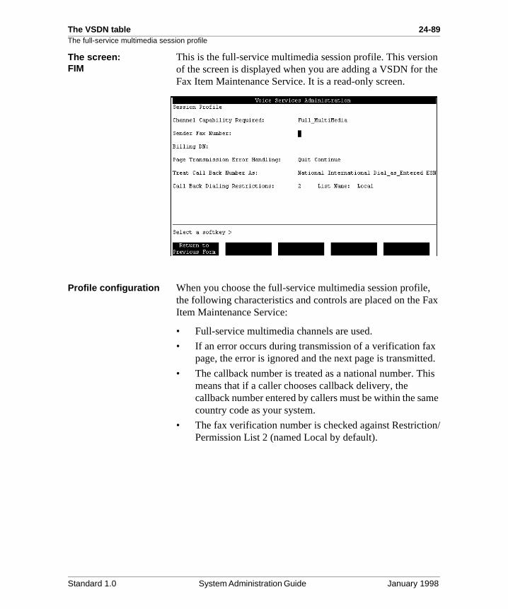
The VSDN table 24-89The full-service multimedia session profile
n the
, ax
x ed.
is
me
n/
The screen: FIM
This is the full-service multimedia session profile. This versioof the screen is displayed when you are adding a VSDN for Fax Item Maintenance Service. It is a read-only screen.
Profile configuration When you choose the full-service multimedia session profilethe following characteristics and controls are placed on the FItem Maintenance Service:
• Full-service multimedia channels are used.
• If an error occurs during transmission of a verification fapage, the error is ignored and the next page is transmitt
• The callback number is treated as a national number. Thmeans that if a caller chooses callback delivery, the callback number entered by callers must be within the sacountry code as your system.
• The fax verification number is checked against RestrictioPermission List 2 (named Local by default).
Standard 1.0 System Administration Guide January 1998
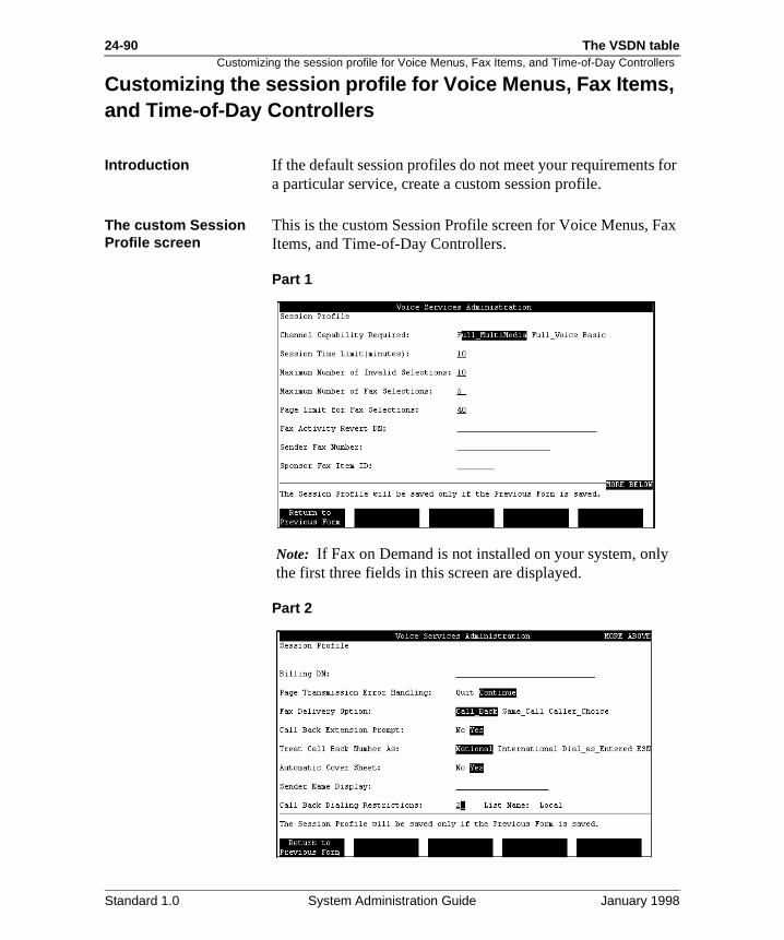
24-90 The VSDN table
for
ax
Customizing the session profile for Voice Menus, Fax Items, and Time-of-Day Controllers
Customizing the session profile for Voice Menus, Fax Items, and Time-of-Day Controllers
Introduction If the default session profiles do not meet your requirementsa particular service, create a custom session profile.
The custom Session Profile screen
This is the custom Session Profile screen for Voice Menus, FItems, and Time-of-Day Controllers.
Part 1
Note: If Fax on Demand is not installed on your system, onlythe first three fields in this screen are displayed.
Part 2
Standard 1.0 System Administration Guide January 1998
The VSDN table 24-91Customizing the session profile for Voice Menus, Fax Items, and Time-of-Day Controllers
Procedure Following is a high-level procedure for creating a custom session profile. Detailed procedures are provided on the corresponding pages.
Step Action See page
1 Specify the channel capability, session time limit, and maximum number of invalid selections.
Requirement: This step is necessary for all Voice Menus, Fax Items, and Time-of-Day Controllers.
24-92
2 Specify fax service options.
Requirement: This step is necessary if the service you are defining is a Fax Item or a Voice Menu or Time-of-Day Controller that invokes a fax service.
24-96
3 Specify call back delivery options.
Requirement: This step is necessary if step 2 was necessary and if the fax delivery option for the service is Call Back or Caller Choice.
24-102
Standard 1.0 System Administration Guide January 1998
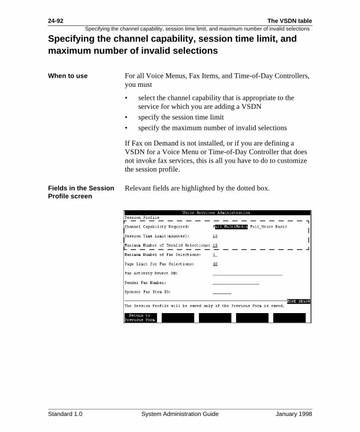
24-92 The VSDN table
s,
e
Specifying the channel capability, session time limit, and maximum number of invalid selections
Specifying the channel capability, session time limit, and maximum number of invalid selections
When to use For all Voice Menus, Fax Items, and Time-of-Day Controlleryou must
• select the channel capability that is appropriate to the service for which you are adding a VSDN
• specify the session time limit
• specify the maximum number of invalid selections
If Fax on Demand is not installed, or if you are defining a VSDN for a Voice Menu or Time-of-Day Controller that doesnot invoke fax services, this is all you have to do to customizthe session profile.
Fields in the Session Profile screen
Relevant fields are highlighted by the dotted box.
Standard 1.0 System Administration Guide January 1998
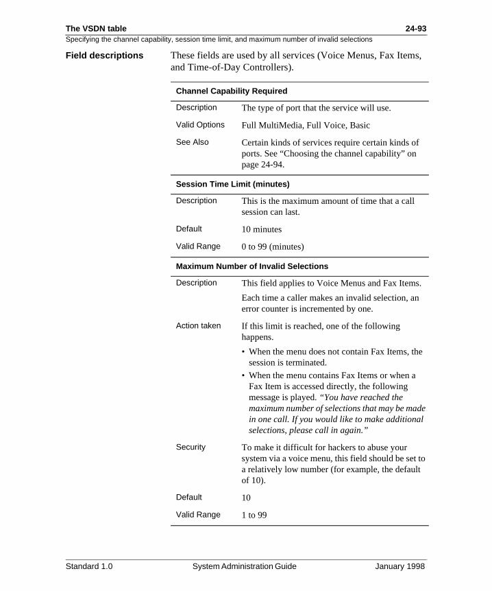
The VSDN table 24-93Specifying the channel capability, session time limit, and maximum number of invalid selections
s,
.
e
de
to
Field descriptions These fields are used by all services (Voice Menus, Fax Itemand Time-of-Day Controllers).
Channel Capability Required
Description The type of port that the service will use.
Valid Options Full MultiMedia, Full Voice, Basic
See Also Certain kinds of services require certain kinds ofports. See “Choosing the channel capability” on page 24-94.
Session Time Limit (minutes)
Description This is the maximum amount of time that a call session can last.
Default 10 minutes
Valid Range 0 to 99 (minutes)
Maximum Number of Invalid Selections
Description This field applies to Voice Menus and Fax Items
Each time a caller makes an invalid selection, anerror counter is incremented by one.
Action taken If this limit is reached, one of the following happens.
• When the menu does not contain Fax Items, thsession is terminated.
• When the menu contains Fax Items or when a Fax Item is accessed directly, the following message is played. “You have reached the maximum number of selections that may be main one call. If you would like to make additionalselections, please call in again.”
Security To make it difficult for hackers to abuse your system via a voice menu, this field should be seta relatively low number (for example, the defaultof 10).
Default 10
Valid Range 1 to 99
Standard 1.0 System Administration Guide January 1998
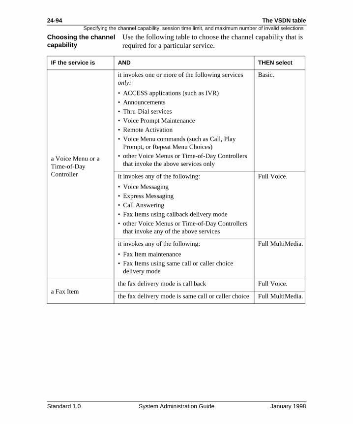
24-94 The VSDN table
is
.
Specifying the channel capability, session time limit, and maximum number of invalid selections
Choosing the channel capability
Use the following table to choose the channel capability thatrequired for a particular service.
IF the service is AND THEN select
a Voice Menu or aTime-of-Day Controller
it invokes one or more of the following services only:
• ACCESS applications (such as IVR)
• Announcements
• Thru-Dial services
• Voice Prompt Maintenance
• Remote Activation
• Voice Menu commands (such as Call, Play Prompt, or Repeat Menu Choices)
• other Voice Menus or Time-of-Day Controllers that invoke the above services only
Basic.
it invokes any of the following:
• Voice Messaging
• Express Messaging
• Call Answering
• Fax Items using callback delivery mode
• other Voice Menus or Time-of-Day Controllers that invoke any of the above services
Full Voice.
it invokes any of the following:
• Fax Item maintenance
• Fax Items using same call or caller choice delivery mode
Full MultiMedia.
a Fax Itemthe fax delivery mode is call back Full Voice.
the fax delivery mode is same call or caller choice Full MultiMedia
Standard 1.0 System Administration Guide January 1998
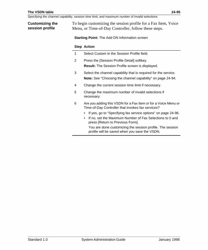
The VSDN table 24-95Specifying the channel capability, session time limit, and maximum number of invalid selections
e
Customizing the session profileTo begin customizing the session profile for a Fax Item, VoicMenu, or Time-of-Day Controller, follow these steps.
Starting Point: The Add DN Information screen
Step Action
1 Select Custom in the Session Profile field.
2 Press the [Session Profile Detail] softkey.
Result: The Session Profile screen is displayed.
3 Select the channel capability that is required for the service.
Note: See “Choosing the channel capability” on page 24-94.
4 Change the current session time limit if necessary.
5 Change the maximum number of invalid selections if necessary.
6 Are you adding this VSDN for a Fax Item or for a Voice Menu or Time-of-Day Controller that invokes fax services?
• If yes, go to “Specifying fax service options” on page 24-96.
• If no, set the Maximum Number of Fax Selections to 0 and press [Return to Previous Form].
You are done customizing the session profile. The session profile will be saved when you save the VSDN.
Standard 1.0 System Administration Guide January 1998
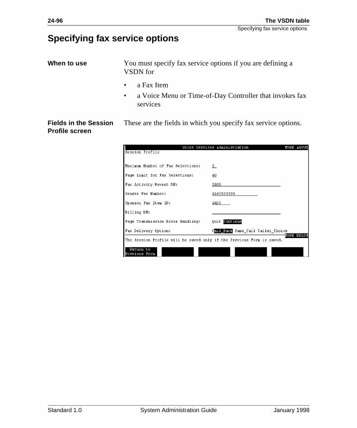
24-96 The VSDN table
.
Specifying fax service options
Specifying fax service options
When to use You must specify fax service options if you are defining a VSDN for
• a Fax Item
• a Voice Menu or Time-of-Day Controller that invokes faxservices
Fields in the Session Profile screen
These are the fields in which you specify fax service options
Standard 1.0 System Administration Guide January 1998
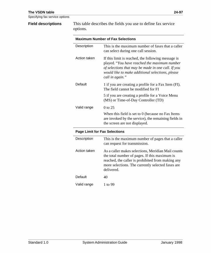
The VSDN table 24-97Specifying fax service options
r
r
in
er
ts
e
Field descriptions This table describes the fields you use to define fax service options.
Maximum Number of Fax Selections
Description This is the maximum number of faxes that a callecan select during one call session.
Action taken If this limit is reached, the following message is played. “You have reached the maximum numbeof selections that may be made in one call. If youwould like to make additional selections, please call in again.”
Default 1 if you are creating a profile for a Fax Item (FI). The field cannot be modified for FI
5 if you are creating a profile for a Voice Menu (MS) or Time-of-Day Controller (TD)
Valid range 0 to 25
When this field is set to 0 (because no Fax Itemsare invoked by the service), the remaining fields the screen are not displayed.
Page Limit for Fax Selections
Description This is the maximum number of pages that a callcan request for transmission.
Action taken As a caller makes selections, Meridian Mail counthe total number of pages. If this maximum is reached, the caller is prohibited from making anymore selections. The currently selected faxes ardelivered.
Default 40
Valid range 1 to 99
Standard 1.0 System Administration Guide January 1998
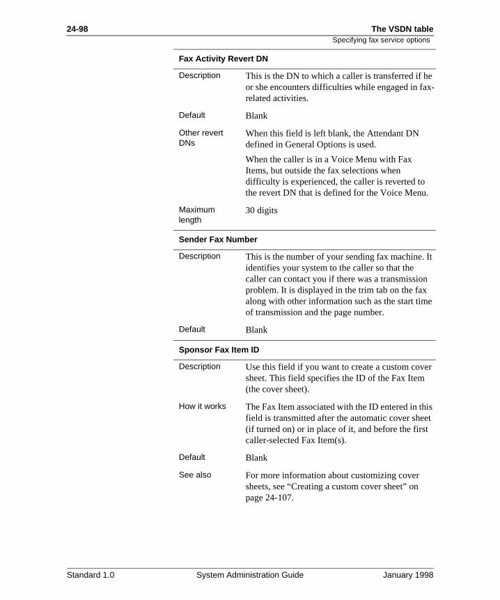
24-98 The VSDN table
e x-
It
n e
r
is et
Specifying fax service options
Fax Activity Revert DN
Description This is the DN to which a caller is transferred if hor she encounters difficulties while engaged in farelated activities.
Default Blank
Other revert DNs
When this field is left blank, the Attendant DN defined in General Options is used.
When the caller is in a Voice Menu with Fax Items, but outside the fax selections when difficulty is experienced, the caller is reverted to the revert DN that is defined for the Voice Menu.
Maximum length
30 digits
Sender Fax Number
Description This is the number of your sending fax machine. identifies your system to the caller so that the caller can contact you if there was a transmissioproblem. It is displayed in the trim tab on the faxalong with other information such as the start timof transmission and the page number.
Default Blank
Sponsor Fax Item ID
Description Use this field if you want to create a custom covesheet. This field specifies the ID of the Fax Item (the cover sheet).
How it works The Fax Item associated with the ID entered in thfield is transmitted after the automatic cover she(if turned on) or in place of it, and before the firstcaller-selected Fax Item(s).
Default Blank
See also For more information about customizing cover sheets, see “Creating a custom cover sheet” on page 24-107.
Standard 1.0 System Administration Guide January 1998
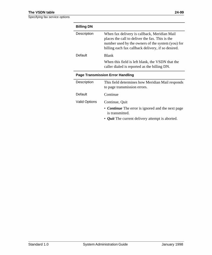
The VSDN table 24-99Specifying fax service options
or
s
e
Billing DN
Description When fax delivery is callback, Meridian Mail places the call to deliver the fax. This is the number used by the owners of the system (you) fbilling each fax callback delivery, if so desired.
Default Blank
When this field is left blank, the VSDN that the caller dialed is reported as the billing DN.
Page Transmission Error Handling
Description This field determines how Meridian Mail respondto page transmission errors.
Default Continue
Valid Options Continue, Quit
• Continue The error is ignored and the next pagis transmitted.
• Quit The current delivery attempt is aborted.
Standard 1.0 System Administration Guide January 1998
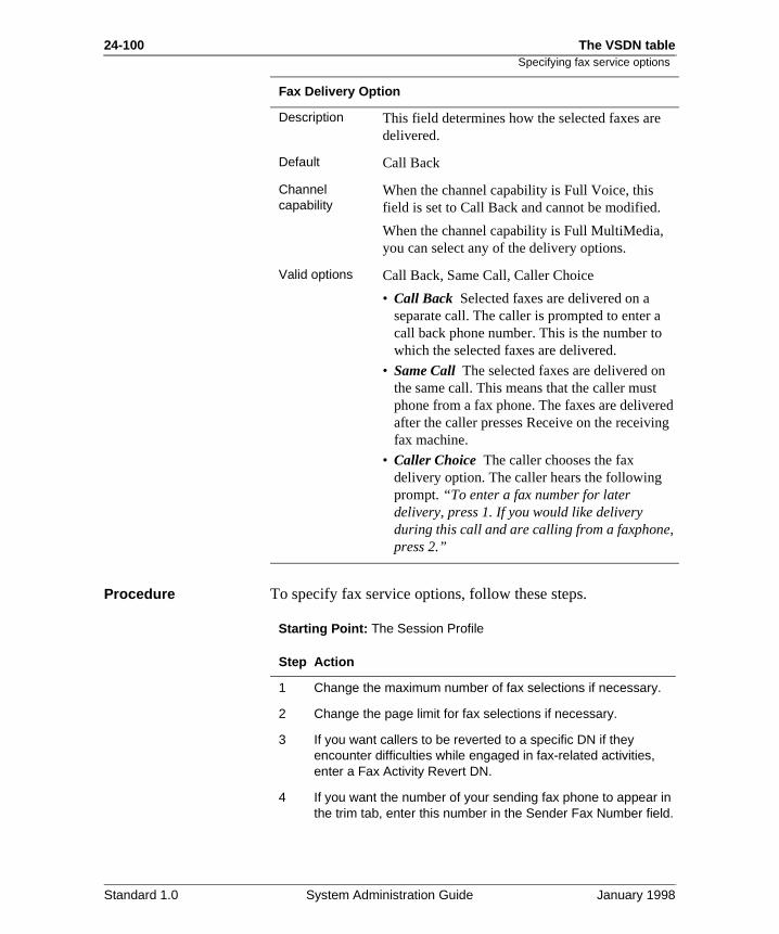
24-100 The VSDN table
ed g
,
Specifying fax service options
Procedure To specify fax service options, follow these steps.
Starting Point: The Session Profile
Fax Delivery Option
Description This field determines how the selected faxes aredelivered.
Default Call Back
Channel capability
When the channel capability is Full Voice, this field is set to Call Back and cannot be modified.
When the channel capability is Full MultiMedia, you can select any of the delivery options.
Valid options Call Back, Same Call, Caller Choice
• Call Back Selected faxes are delivered on a separate call. The caller is prompted to enter acall back phone number. This is the number towhich the selected faxes are delivered.
• Same Call The selected faxes are delivered onthe same call. This means that the caller must phone from a fax phone. The faxes are deliverafter the caller presses Receive on the receivinfax machine.
• Caller Choice The caller chooses the fax delivery option. The caller hears the following prompt. “To enter a fax number for later delivery, press 1. If you would like delivery during this call and are calling from a faxphonepress 2.”
Step Action
1 Change the maximum number of fax selections if necessary.
2 Change the page limit for fax selections if necessary.
3 If you want callers to be reverted to a specific DN if they encounter difficulties while engaged in fax-related activities, enter a Fax Activity Revert DN.
4 If you want the number of your sending fax phone to appear in the trim tab, enter this number in the Sender Fax Number field.
Standard 1.0 System Administration Guide January 1998
The VSDN table 24-101Specifying fax service options
5 If you have created a custom cover sheet, enter its ID in the Sponsor Fax Item ID field.
6 If you want calls to this VSDN to be reported as a specific number (as the billing DN), enter it in the Billing DN field.
7 If an error is encountered during transmission, do you want Meridian Mail to ignore it and continue with the next page?
• If yes, select Continue.
• If no, select Quit.
8 If the Channel Capability is Full MultiMedia, select the fax delivery option.
9 Is the Fax Delivery Option field set to Call Back or Caller Choice?
• If yes, go to “Specifying callback delivery options” on page 24-102.
• If no, press [Return to Previous Form]. You are done customizing the session profile. The session profile will be saved when you save the VSDN.
Step Action
IF you want THEN select
faxes to be delivered on the same call on which the caller dialed into Meridian Mail
Same Call.
faxes to be delivered on a separate call, placed by Meridian Mail, to a call back number specified by the caller
Call Back.
callers to choose how they want their fax selections delivered (same call or call back)
Caller Choice.
Standard 1.0 System Administration Guide January 1998
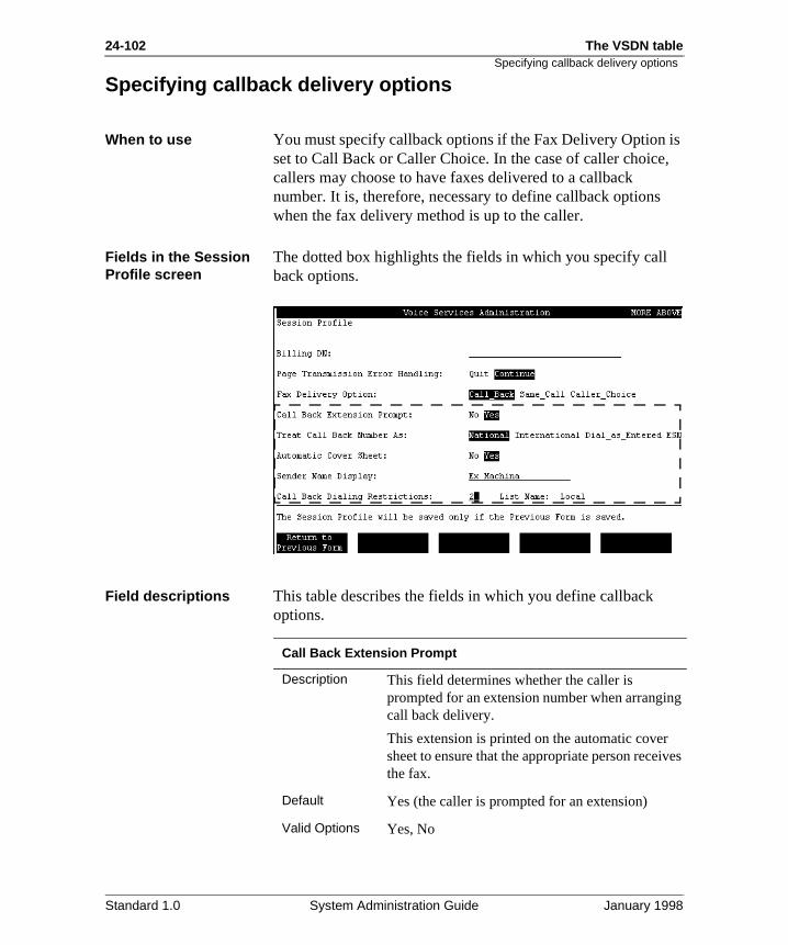
24-102 The VSDN table
is ,
g
ves
Specifying callback delivery options
Specifying callback delivery options
When to use You must specify callback options if the Fax Delivery Option set to Call Back or Caller Choice. In the case of caller choicecallers may choose to have faxes delivered to a callback number. It is, therefore, necessary to define callback optionswhen the fax delivery method is up to the caller.
Fields in the Session Profile screen
The dotted box highlights the fields in which you specify callback options.
Field descriptions This table describes the fields in which you define callback options.
Call Back Extension Prompt
Description This field determines whether the caller is prompted for an extension number when arrangincall back delivery.
This extension is printed on the automatic cover sheet to ensure that the appropriate person receithe fax.
Default Yes (the caller is prompted for an extension)
Valid Options Yes, No
Standard 1.0 System Administration Guide January 1998
The VSDN table 24-103Specifying callback delivery options
he
an
4.
an .
et a
Treat Call Back Number As
Description This field determines the format of numbers that callers can enter for callback purposes and how tuser is prompted to enter a callback number.
Default National
Valid Options National, International, Dial as Entered, ESN
• National Only callers with callback numbers within the same country code as your system cuse the service.
• International Callers from other countries can use the service.
• Dial as Entered Callers can enter a callback number in any format. Callers must, however, know what format is necessary depending on where they are located relative to your system.
• ESN Only callers that are on your ESN networkcan use the service.
See also See “Fax callback number formats” on page 24-7
Automatic Cover Sheet
Description This is a system-generated cover sheet that you cchoose to transmit along with selected Fax Items
In the case of caller choice delivery, this cover sheet is sent only if callback delivery is chosen.
Default Yes
Valid Options Yes, No
See also If you want to create and use a custom cover sheinstead of using the automatic one, see “Creatingcustom cover sheet” on page 24-107.
Standard 1.0 System Administration Guide January 1998
24-104 The VSDN table
on
ll
.
Specifying callback delivery options
Sender Name Display
Description The sender name is displayed on the automatic cover sheet in the From field. This is typically thename of your organization or department.
Conditions of display
This field is displayed if the Automatic Cover Sheet field is set to Yes.
Default Blank
Maximum length
20 characters
Call Back Dialing Restrictions
Description These are the dialing restrictions that are placed the callback numbers that callers enter.
It is important to restrict this number since you wibe charged for all callback fax deliveries.
Default Restriction/Permission List 2
Valid Options Any of the available restriction/permission lists (1–80), or 0 to create a custom list for the service
Standard 1.0 System Administration Guide January 1998
The VSDN table 24-105Specifying callback delivery options
Procedure To specify callback options, follow these steps.
Starting Point: The Session Profile
Step Action
1 Do you want callers to be prompted for an extension number so that it can appear on the automatic cover sheet?
• If yes, select Yes in the Call Back Extension Prompt field.• If no, select No.
2 Select the format of callback numbers to which you want to allow fax delivery in the Treat Call Back Number As field.
3 Do you want the system-generated automatic cover sheet to be transmitted with the selected Fax Items?
• If yes, select Yes in the Automatic Cover Sheet field.
• If no, select No.
4 If the automatic cover sheet is enabled, do you want to identify your organization or department, or both, as the source of the fax on the cover sheet?
• If yes, enter your organization’s or department’s name, or both, in the Sender Name Display field.
• If no, leave the field blank.
5 Do you want to create a custom restriction/permission list for this service?
• If yes, go to step 6.• If no, enter the number of the predefined restriction/
permission list that you want to assign to this service and go to step 8.
IF you want faxes to be delivered THEN select
to callback numbers within your country code only
National.
to international numbers International.
to on-switch extensions, to numbers in a CDP network, or to numbers as they are entered
Dial as Entered.
to numbers that are on your ESN network only
ESN.
Standard 1.0 System Administration Guide January 1998
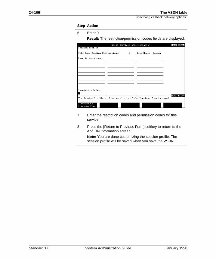
24-106 The VSDN table
Specifying callback delivery options6 Enter 0.
Result: The restriction/permission codes fields are displayed.
7 Enter the restriction codes and permission codes for this service.
8 Press the [Return to Previous Form] softkey to return to the Add DN Information screen.
Note: You are done customizing the session profile. The session profile will be saved when you save the VSDN.
Step Action
Standard 1.0 System Administration Guide January 1998
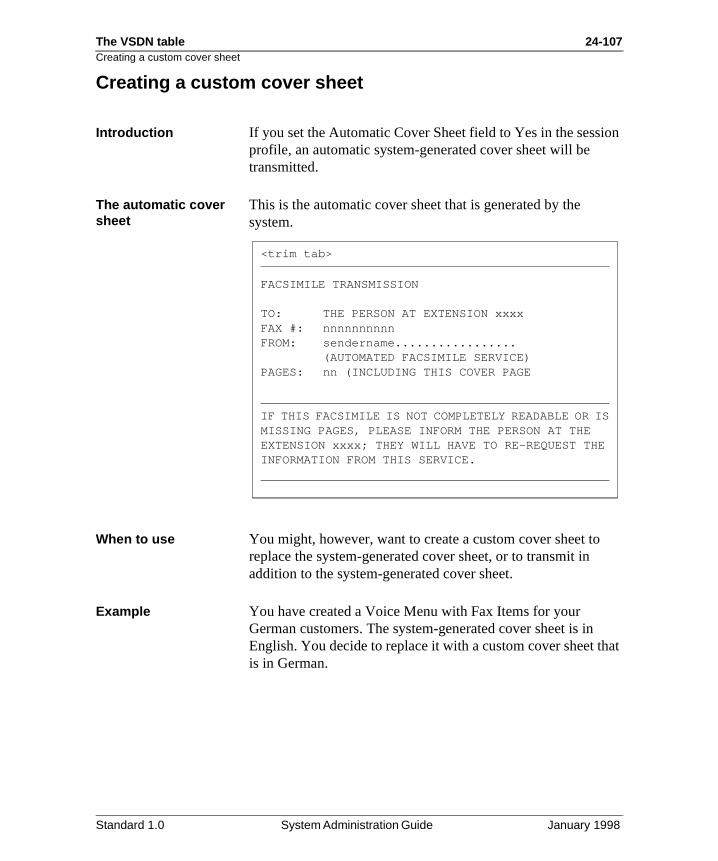
The VSDN table 24-107Creating a custom cover sheet
ion
hat
Creating a custom cover sheet
Introduction If you set the Automatic Cover Sheet field to Yes in the sessprofile, an automatic system-generated cover sheet will be transmitted.
The automatic cover sheet
This is the automatic cover sheet that is generated by the system.
When to use You might, however, want to create a custom cover sheet toreplace the system-generated cover sheet, or to transmit in addition to the system-generated cover sheet.
Example You have created a Voice Menu with Fax Items for your German customers. The system-generated cover sheet is inEnglish. You decide to replace it with a custom cover sheet tis in German.
<trim tab>
FACSIMILE TRANSMISSION
TO: THE PERSON AT EXTENSION xxxxFAX #: nnnnnnnnnnFROM: sendername.................
(AUTOMATED FACSIMILE SERVICE)PAGES: nn (INCLUDING THIS COVER PAGE
IF THIS FACSIMILE IS NOT COMPLETELY READABLE OR ISMISSING PAGES, PLEASE INFORM THE PERSON AT THE EXTENSION xxxx; THEY WILL HAVE TO RE-REQUEST THEINFORMATION FROM THIS SERVICE.
Standard 1.0 System Administration Guide January 1998
24-108 The VSDN table
r
or
in
Creating a custom cover sheet
Creating a custom cover sheet
To create a custom cover sheet, you must do the following.
1. Create a Fax Item which will serve as the cover sheet foyour service.
For more information, refer to the Fax on Demand Application Guide.
2. Create a VSDN for the service (the stand-alone Fax Itemthe service that invokes it).
3. Customize the session profile for the service.
- Enter the ID of the Fax Item (that is the cover sheet) the Sponsor Fax Item ID field.
- If you want to suppress the system-generated cover sheet, set the Automatic Cover Sheet field to No.
Standard 1.0 System Administration Guide January 1998
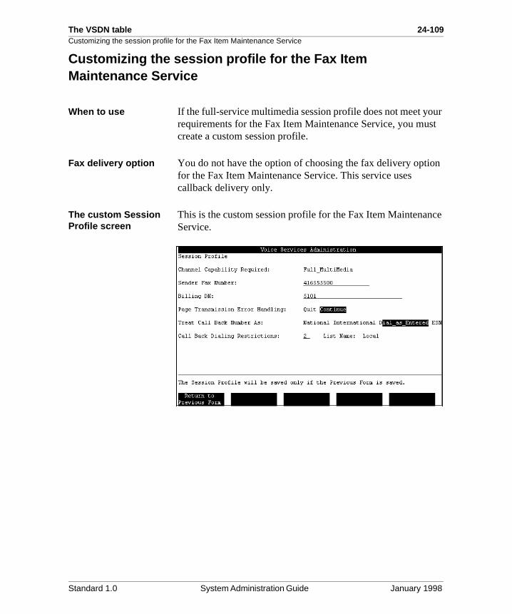
The VSDN table 24-109Customizing the session profile for the Fax Item Maintenance Service
ur st
n
ce
Customizing the session profile for the Fax Item Maintenance Service
When to use If the full-service multimedia session profile does not meet yorequirements for the Fax Item Maintenance Service, you mucreate a custom session profile.
Fax delivery option You do not have the option of choosing the fax delivery optiofor the Fax Item Maintenance Service. This service uses callback delivery only.
The custom Session Profile screen
This is the custom session profile for the Fax Item MaintenanService.
Standard 1.0 System Administration Guide January 1998
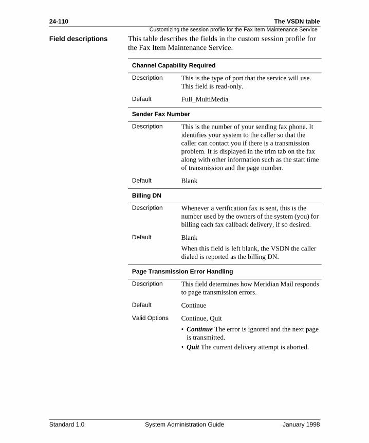
24-110 The VSDN table
or
e
or
s
e
Customizing the session profile for the Fax Item Maintenance Service
Field descriptions This table describes the fields in the custom session profile fthe Fax Item Maintenance Service.
Channel Capability Required
Description This is the type of port that the service will use. This field is read-only.
Default Full_MultiMedia
Sender Fax Number
Description This is the number of your sending fax phone. It identifies your system to the caller so that the caller can contact you if there is a transmission problem. It is displayed in the trim tab on the faxalong with other information such as the start timof transmission and the page number.
Default Blank
Billing DN
Description Whenever a verification fax is sent, this is the number used by the owners of the system (you) fbilling each fax callback delivery, if so desired.
Default Blank
When this field is left blank, the VSDN the caller dialed is reported as the billing DN.
Page Transmission Error Handling
Description This field determines how Meridian Mail respondto page transmission errors.
Default Continue
Valid Options Continue, Quit
• Continue The error is ignored and the next pagis transmitted.
• Quit The current delivery attempt is aborted.
Standard 1.0 System Administration Guide January 1998
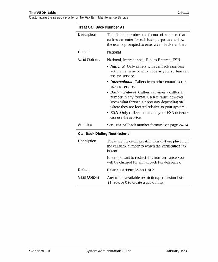
The VSDN table 24-111Customizing the session profile for the Fax Item Maintenance Service
.
an
k
4.
on
Treat Call Back Number As
Description This field determines the format of numbers that callers can enter for call back purposes and howthe user is prompted to enter a call back number
Default National
Valid Options National, International, Dial as Entered, ESN
• National Only callers with callback numbers within the same country code as your system cuse the service.
• International Callers from other countries can use the service.
• Dial as Entered Callers can enter a callback number in any format. Callers must, however, know what format is necessary depending on where they are located relative to your system.
• ESN Only callers that are on your ESN networcan use the service.
See also See “Fax callback number formats” on page 24-7
Call Back Dialing Restrictions
Description These are the dialing restrictions that are placed the callback number to which the verification fax is sent.
It is important to restrict this number, since you will be charged for all callback fax deliveries.
Default Restriction/Permission List 2
Valid Options Any of the available restriction/permission lists (1–80), or 0 to create a custom list.
Standard 1.0 System Administration Guide January 1998
24-112 The VSDN table
Customizing the session profile for the Fax Item Maintenance ServiceProcedure To customize the session profile for Fax Item Maintenance, follow these steps.
Starting Point: The Add DN Information screen
Step Action
1 Select Custom in the Session Profile field.
2 Press the [Session Profile Detail] softkey.
Result: The Session Profile screen is displayed.
3 Do you want the number of the sending fax machine to show up in the fax trim tab?
• If yes, enter the number of the sending fax machine in the Sender Fax Number field.
• If no, go to step 4.
4 Do you want calls to this VSDN to be reported as a specific number (as the billing DN) other than this VSDN?
• If yes, enter this number in the Billing DN field. • If no, leave this field blank.
5 Do you want fax delivery to continue if an error is encountered during transmission?
• If yes, select Continue in the Error Transmission Handling field.
• If no, select Quit.
6 Select the kind of call back numbers to which you want to allow verification fax delivery in the Treat Call Back Number As field.
IF you want faxes to be delivered THEN select
to call back numbers within your country code only
National.
to international numbers International.
to on-switch extensions, to numbers in a CDP network, or to numbers as they are entered
Dial as Entered.
to numbers that are on your ESN network only
ESN.
Standard 1.0 System Administration Guide January 1998
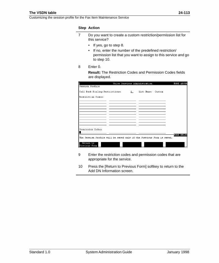
The VSDN table 24-113Customizing the session profile for the Fax Item Maintenance Service
7 Do you want to create a custom restriction/permission list for this service?
• If yes, go to step 8.• If no, enter the number of the predefined restriction/
permission list that you want to assign to this service and go to step 10.
8 Enter 0.
Result: The Restriction Codes and Permission Codes fields are displayed.
9 Enter the restriction codes and permission codes that are appropriate for the service.
10 Press the [Return to Previous Form] softkey to return to the Add DN Information screen.
Step Action
Standard 1.0 System Administration Guide January 1998

24-114 The VSDN table
Customizing the session profile for the Fax Item Maintenance ServiceStandard 1.0 System Administration Guide January 1998
The VSDN table 24-115
Section F: Viewing, modifying, and deleting VSDNs
In this section
Viewing and modifying a VSDN or session profile, or both 24-116
Deleting a VSDN 24-119
Standard 1.0 System Administration Guide January 1998
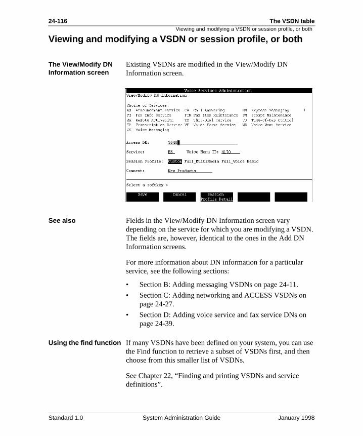
24-116 The VSDN table
N.
use n
Viewing and modifying a VSDN or session profile, or both
Viewing and modifying a VSDN or session profile, or both
The View/Modify DN Information screen
Existing VSDNs are modified in the View/Modify DN Information screen.
See also Fields in the View/Modify DN Information screen vary depending on the service for which you are modifying a VSDThe fields are, however, identical to the ones in the Add DN Information screens.
For more information about DN information for a particular service, see the following sections:
• Section B: Adding messaging VSDNs on page 24-11.
• Section C: Adding networking and ACCESS VSDNs on page 24-27.
• Section D: Adding voice service and fax service DNs onpage 24-39.
Using the find function If many VSDNs have been defined on your system, you can the Find function to retrieve a subset of VSDNs first, and thechoose from this smaller list of VSDNs.
See Chapter 22, “Finding and printing VSDNs and service definitions”.
Standard 1.0 System Administration Guide January 1998
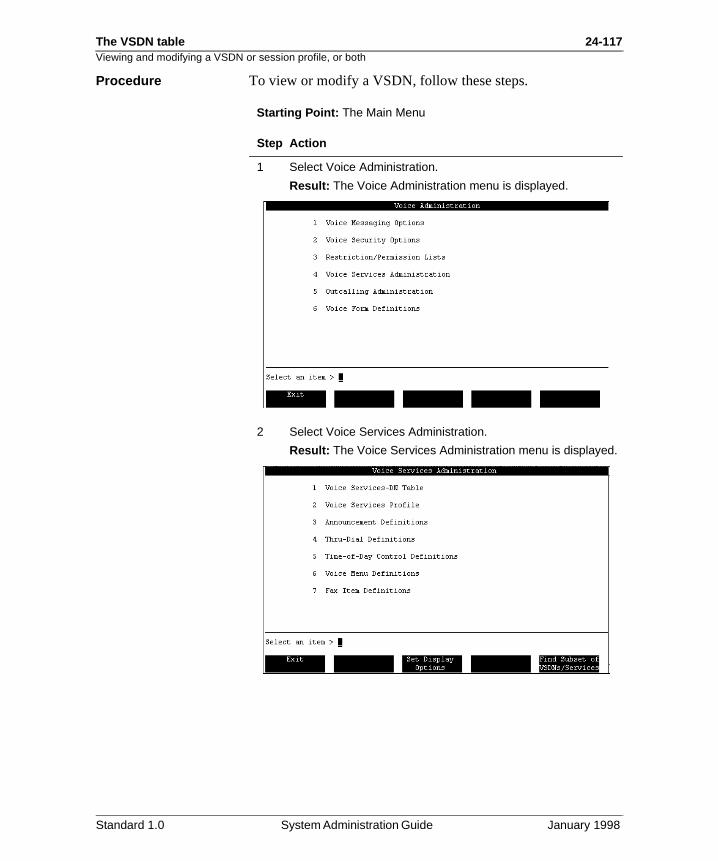
The VSDN table 24-117Viewing and modifying a VSDN or session profile, or both
Procedure To view or modify a VSDN, follow these steps.
Starting Point: The Main Menu
Step Action
1 Select Voice Administration.
Result: The Voice Administration menu is displayed.
2 Select Voice Services Administration.
Result: The Voice Services Administration menu is displayed.
Standard 1.0 System Administration Guide January 1998
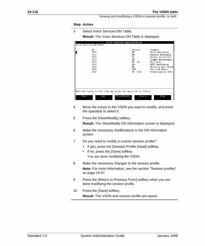
24-118 The VSDN table
Viewing and modifying a VSDN or session profile, or both3 Select Voice Services-DN Table.
Result: The Voice Services-DN Table is displayed.
4 Move the cursor to the VSDN you want to modify, and press the spacebar to select it.
5 Press the [View/Modify] softkey.
Result: The View/Modify DN Information screen is displayed.
6 Make the necessary modifications in the DN information screen.
7 Do you need to modify a custom session profile?
• If yes, press the [Session Profile Detail] softkey.• If no, press the [Save] softkey.
You are done modifying the VSDN.
8 Make the necessary changes to the session profile.
Note: For more information, see the section "Session profiles" on page 24-67.
9 Press the [Return to Previous Form] softkey when you are done modifying the session profile.
10 Press the [Save] softkey.
Result: The VSDN and session profile are saved.
Step Action
Standard 1.0 System Administration Guide January 1998
The VSDN table 24-119Deleting a VSDN
use n
Deleting a VSDN
The Delete DN Information screen
Existing VSDNs are deleted from the Delete DN Informationscreen.
Using the find function If many VSDNs have been defined on your system, you can the Find function to retrieve a subset of VSDNs first, and thechoose from this smaller list of VSDNs.
See Chapter 22, “Finding and printing VSDNs and service definitions”.
Standard 1.0 System Administration Guide January 1998
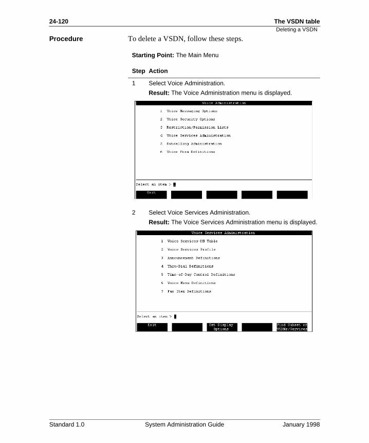
24-120 The VSDN table
Deleting a VSDNProcedure To delete a VSDN, follow these steps.
Starting Point: The Main Menu
Step Action
1 Select Voice Administration.
Result: The Voice Administration menu is displayed.
2 Select Voice Services Administration.
Result: The Voice Services Administration menu is displayed.
Standard 1.0 System Administration Guide January 1998
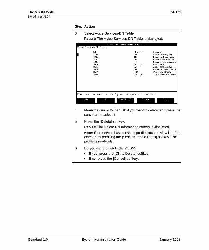
The VSDN table 24-121Deleting a VSDN
3 Select Voice Services-DN Table.
Result: The Voice Services-DN Table is displayed.
4 Move the cursor to the VSDN you want to delete, and press the spacebar to select it.
5 Press the [Delete] softkey.
Result: The Delete DN Information screen is displayed.
Note: If the service has a session profile, you can view it before deleting by pressing the [Session Profile Detail] softkey. The profile is read-only.
6 Do you want to delete the VSDN?
• If yes, press the [OK to Delete] softkey.• If no, press the [Cancel] softkey.
Step Action
Standard 1.0 System Administration Guide January 1998

24-122 The VSDN tableDeleting a VSDN
Standard 1.0 System Administration Guide January 1998
Chapter 25
Voice services profile
In this chapter
Overview 25-2
Timeouts 25-3
How timeouts work 25-4
Modifying the voice services profile 25-6
25-2 Voice services profile Overview
d file
ts. u
Overview
Introduction This chapter provides an overview of the use of timeouts, anexplanations of all the parameters of the Voice Services Proscreen.
The Voice Services Profile screen
The Voice Services Profile screen displays all the general parameters that apply to all voice services, including timeouDefault values are assigned when the system is installed. Yocan modify these values by following the procedure on page 25-6.
Standard 1.0 System Administration Guide January 1998
Voice services profile 25-3Timeouts
er
n
not ring
nu. e ll.
a as
ion,
pts
Timeouts
Definition Timeout values determine how long the system will wait undcertain conditions before the system takes action (such as disconnecting or playing a prompt). Timeouts are important because they aid callers by playing appropriate prompts whethe system has not received correct input.
Types of timeouts There are three types of timeouts to define:
• command entry
• short disconnect
• record
Examples The command entry timeout is used when the system does receive an anticipated response from the caller, such as entean extension number or making a selection from a voice meThis allows for the system to respond with a prompt to aid thcaller, transfer the call to the revert DN, or disconnect the ca
The short disconnect timeout is used for disconnecting fromThru-Dial service or from a voice menu, because the caller hnot input an extension number or selected a voice menu optafter entering the service.
The record disconnect timeout is used during recording promto prevent recording unnecessary silences.
Standard 1.0 System Administration Guide January 1998
25-4 Voice services profile How timeouts work
ing
5 onds.
g
l
ing
,
no .
ll,
o
How timeouts work
Description Timeout values are used to determine how long the system waits before taking some sort of action when an expected response is not received. The three types of timeouts are explained below.
Command entry timeout
The command entry timeout is used when the system is waitfor a response from the caller. It allows you to set time parameters which, when exceeded, prompt the system for aresponse. The default value for command entry timeout is 3.seconds. The accepted values are between 1.0 and 5.0 sec
Command entry timeout may be used for any of the followinsituations.
AnnouncementsWhen announcements are accessed directly, the system wilwait this amount of time before disconnecting the call. This timeout is intended to put a limit on how long a caller will remain connected if the caller stays on the line and does nothafter the announcement is played.
In the case where an announcement is played multiple timesthis amount of silence will be heard between each play.
Voice menuThis timeout is used for initial no response and delayed response. You can define the action to be taken for an initialresponse and delayed response in the voice menu definition
Note: If you are using a voice menu to accept AMIS or Enterprise Networking calls, or both, set this timeout to the maximum allowed value of five seconds. If this field is set toless than five seconds, an AMIS or Enterprise Networking caor both, may be prematurely disconnected. The initial no response action in the voice menu definition should be set trepeat menu choices.
Standard 1.0 System Administration Guide January 1998
Voice services profile 25-5How timeouts work
n the
an hen is d o
ch llers
to
ing
nd,
Thru-Dial serviceCommand entry timeout is used if the system is waiting for ainitial response (such as an extension number or name), or ifcaller has provided keypad input at some point but is now delaying in providing further input.
Fax information serviceWith a fax information service, a caller may be prompted for action (such as entering a callback number or extension). Wthe caller does not respond and the command entry timeoutexceeded, a help prompt is played. If the caller still does notenter the required information, the prompt is played a secontime. If the system times out again, the caller is transferred tthe revert DN defined in the session profile.
Short disconnect timeout
The short disconnect timeout is used to disconnect a call, suas when the command entry timeout has been exceeded. Caare usually given several opportunities to provide responsesbefore the short disconnect timeout is used.
The default value is 10.0 seconds. Valid values are from 1.030.0 seconds.
This timeout value is used in the following situations:
• disconnecting from a thru-dial service
• disconnection from a voice menu
Record timeout This timeout value is used with the recording of prompts for voice menus, announcements, and Thru-Dial services. If durrecording this amount of silence is recorded, the system willdisconnect the session.
The default is 02:00 (mm:ss). Valid values are from 00:06 to05:00. This affects all voice services other than Fax on Demaand Voice Messaging and its associated features (login, callanswering, express messaging).
Standard 1.0 System Administration Guide January 1998
25-6 Voice services profile Modifying the voice services profile
ters
Modifying the voice services profile
Introduction The Voice Services Profile screen shows the general parameconfigured for all voice services (with the exception of voice messaging services).
Procedure To make changes to the parameters in the Voice Services Profile, follow these steps.
Starting Point: The Main Menu
Step Action
1 Select Voice Administration.
Result: The Voice Administration screen appears.
2 Select Voice Services Administration.
Result: The Voice Services Administration screen appears.
3 Select Voice Services Profile.
Result: The Voice Services Profile screen appears.
4 Enter all changes you want to make to the parameters in this screen.
5 When you have made all the necessary changes, press [Save] and then [Exit] to return to the previous screen.
Press [Cancel] to return to the previous screen without saving changes.
Standard 1.0 System Administration Guide January 1998
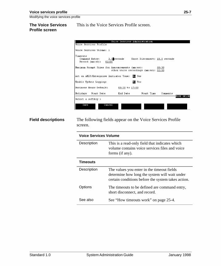
Voice services profile 25-7Modifying the voice services profile
.
The Voice Services Profile screen
This is the Voice Services Profile screen.
Field descriptions The following fields appear on the Voice Services Profile screen.
Voice Services Volume
Description This is a read-only field that indicates which volume contains voice services files and voice forms (if any).
Timeouts
Description The values you enter in the timeout fields determine how long the system will wait under certain conditions before the system takes action
Options The timeouts to be defined are command entry, short disconnect, and record.
See also See “How timeouts work” on page 25-4.
Standard 1.0 System Administration Guide January 1998
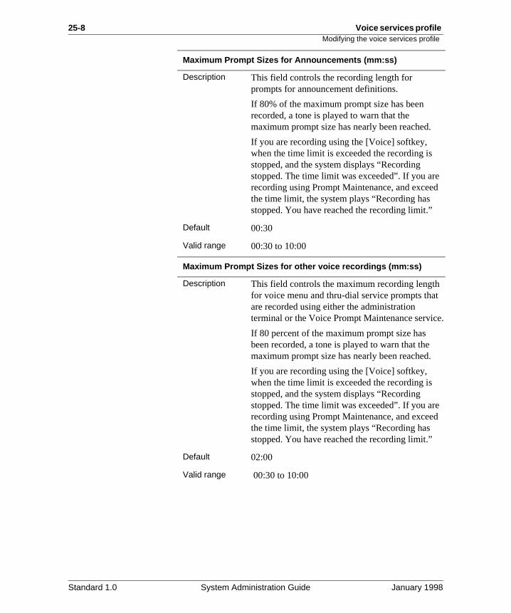
25-8 Voice services profile Modifying the voice services profile
e d
t
e.
e d
Maximum Prompt Sizes for Announcements (mm:ss)
Description This field controls the recording length for prompts for announcement definitions.
If 80% of the maximum prompt size has been recorded, a tone is played to warn that the maximum prompt size has nearly been reached.
If you are recording using the [Voice] softkey, when the time limit is exceeded the recording is stopped, and the system displays “Recording stopped. The time limit was exceeded”. If you arrecording using Prompt Maintenance, and exceethe time limit, the system plays “Recording has stopped. You have reached the recording limit.”
Default 00:30
Valid range 00:30 to 10:00
Maximum Prompt Sizes for other voice recordings (mm:ss)
Description This field controls the maximum recording lengthfor voice menu and thru-dial service prompts thaare recorded using either the administration terminal or the Voice Prompt Maintenance servic
If 80 percent of the maximum prompt size has been recorded, a tone is played to warn that the maximum prompt size has nearly been reached.
If you are recording using the [Voice] softkey, when the time limit is exceeded the recording is stopped, and the system displays “Recording stopped. The time limit was exceeded”. If you arrecording using Prompt Maintenance, and exceethe time limit, the system plays “Recording has stopped. You have reached the recording limit.”
Default 02:00
Valid range 00:30 to 10:00
Standard 1.0 System Administration Guide January 1998
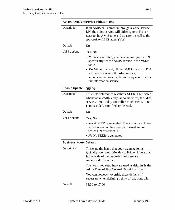
Voice services profile 25-9Modifying the voice services profile
e
r
ed al x
e
the
.
Act on AMIS/Enterprise Initiator Tone
Description If an AMIS call comes in through a voice serviceDN, the voice service will either ignore (No) or react to the AMIS tone and transfer the call to thappropriate AMIS agent (Yes).
Default No
Valid options Yes, No
• No When selected, you have to configure a DNspecifically for the AMIS service in the VSDN table.
• Yes When selected, allows AMIS to share a DNwith a voice menu, thru-dial service, announcement service, time-of-day controller ofax information service.
Enable Update Logging
Description This field determines whether a SEER is generatwhenever a VSDN entry, announcement, thru-diservice, time-of-day controller, voice menu, or faitem is added, modified, or deleted.
Default No
Valid options Yes, No
• Yes A SEER is generated. This allows you to sewhich operation has been performed and on which DN or service ID.
• No No SEER is generated.
Business Hours Default
Description These are the hours that your organization is typically open from Monday to Friday. Hours thatfall outside of the range defined here are considered off-hours.
The hours you enter here are used as defaults in Add a Time of Day Control Definition screen.
You can however, override these defaults if necessary when defining a time-of-day controller
Default 08:30 to 17:00
Standard 1.0 System Administration Guide January 1998
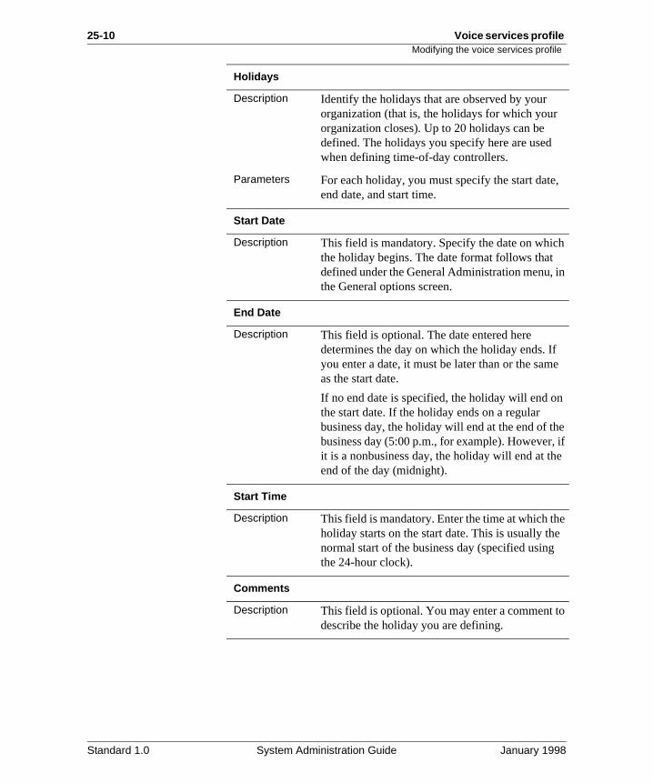
25-10 Voice services profile Modifying the voice services profile
,
h
in
e
e if e
e e
o
Holidays
Description Identify the holidays that are observed by your organization (that is, the holidays for which your organization closes). Up to 20 holidays can be defined. The holidays you specify here are usedwhen defining time-of-day controllers.
Parameters For each holiday, you must specify the start dateend date, and start time.
Start Date
Description This field is mandatory. Specify the date on whicthe holiday begins. The date format follows that defined under the General Administration menu, the General options screen.
End Date
Description This field is optional. The date entered here determines the day on which the holiday ends. Ifyou enter a date, it must be later than or the samas the start date.
If no end date is specified, the holiday will end onthe start date. If the holiday ends on a regular business day, the holiday will end at the end of thbusiness day (5:00 p.m., for example). However,it is a nonbusiness day, the holiday will end at thend of the day (midnight).
Start Time
Description This field is mandatory. Enter the time at which thholiday starts on the start date. This is usually thnormal start of the business day (specified usingthe 24-hour clock).
Comments
Description This field is optional. You may enter a comment tdescribe the holiday you are defining.
Standard 1.0 System Administration Guide January 1998
Chapter 26
Class of Service administration
In this chapter
Overview 26-2
Section A: Introduction to Class of Service 26-3
Section B: Adding, changing, printing, and deleting System Classes of Service
26-9
Section C: Assigning Classes of Service to users 26-63
26-2 Class of Service administration Overview
to
Overview
Introduction Class of Service (COS) administration includes
• defining the system’s Classes of Service (COSs) (Up 15 COSs are permitted plus personal COSs.)
• assigning a COS for each individual user
Section A This section is the Introduction to Class of Service. It includes concepts and types of COS.
Section B This section gives details and procedures on creating (adding), changing, printing, and deleting System COSs.
Section C This section discusses various factors involved with assigning users to COSs.
Standard 1.0 System Administration Guide January 1998
Class of Service administration 26-3
Section A: Introduction to Class of Service
In this section
What is a Class of Service? 26-4
System Class of Service versus Personal Class of Service 26-6
How Class of Service is administered 26-7
Standard 1.0 System Administration Guide January 1998
26-4 Class of Service administration What is a Class of Service?
r cify
of
er
an
for
at ers
may
e
What is a Class of Service?
Description A Class of Service (COS) is a template that contains information about the capabilities that a user has and the values that are assigned to specific parameters. It is essentially a method of classifying users according to theineeds. When you add a user to the system, you must spethe Class of Service to which he or she belongs.
The Meridian Mail COS applies dialing restrictions to Meridian Mail features, controls Meridian Mail resources, and determines which features are available to the owner the mailbox.
Meridian 1 classes of service
The Meridian Mail Class of Service feature should not be confused with Class of Service on the Meridian 1/SL-1 switch. Meridian 1 Class of Service applies certain dialingrestrictions to lines or sets, or trunks, not to Meridian Mail features. (See “Access restrictions” in the X11 Software Features Guide [NTP 553-3001-305].)
Example Before adding users, you should carefully consider the ustypes that you need to represent with COSs. The followingscenario provides an example of the kinds of COSs you ccreate (add).
For instance, you might only need to add three COSs: onesecretaries, one for executives, and a standard one for allother employees. If employees in certain departments arefound to have different needs, you could add one for Accounting, one for Engineering, and so on. The COSs thyou end up creating will depend entirely on the types of usthat you will be adding to the system.
Once you have created your COSs and added users, you realize that a particular group of users requires some additional capabilities. You don’t have to change each individual user. You only need to change the settings in thCOS, and all the users assigned to that COS will automatically pick up the changes.
Standard 1.0 System Administration Guide January 1998
Class of Service administration 26-5What is a Class of Service?
n ,
S for l
.
If an individual user requests additional functionality (or evereduced functionality) or greater mailbox storage capacityyou can do one of two things: reassign the user to anotherCOS that meets his or her needs, or create a personal COthat user (only if no existing COSs are adequate). PersonaCOSs are described in more detail in the following section
Standard 1.0 System Administration Guide January 1998
26-6 Class of Service administration System Class of Service versus Personal Class of Service
will OS,
S is
Ss and e
System Class of Service versus Personal Class of Service
System COS Up to 15 COSs can be defined. When adding a user, you assign him or her to one of these COSs or to a Personal Cif necessary.
Personal COS In addition to the 15 system COSs, the personal COS will always be available when adding a user. The personal COa special class. It allows you to deal with those users whorequire capabilities that do not fit any existing COS. A mailbox with a personal COS remains independent of changes made to other COSs.
Keep in mind, however, that as the number of personal COincreases, the task of maintaining your classes of service users will become more difficult since they all will have to bmanaged.
Standard 1.0 System Administration Guide January 1998
Class of Service administration 26-7How Class of Service is administered
OS
e ses
s of
How Class of Service is administered
Planning, adding, and assigning Classes of Service (COSs)
These are the steps involved in planning, adding, and assigning COSs.
Changing COS for one or several users
These are the steps involved in changing users from one Cto another.
Multiple Administration Terminals
If you have the Multiple Administration Terminal feature installed in your system and you are logged in at a MultiplAdministration Terminal (MAT), you can only view existingClasses of Service. You cannot add, modify, or delete Clasof Service from this terminal.
Stage Description
1 Plan the COSs for the system based on the known needthe local users.
2 Add the COSs that have been planned.
3 Assign the COSs to the system.
4 Assign users to the COSs according to their needs.
Stage Description
1 Analyze the users’ current needs.
2 Assign the users to COSs that meet their current requirements.
Standard 1.0 System Administration Guide January 1998

26-8 Class of Service administration How Class of Service is administered
Standard 1.0 System Administration Guide January 1998
Class of Service administration 26-9
Section B: Adding, changing, printing, and deleting System Classes of Service
In this section
Adding a Class of Service 26-10
The Add Class of Service screen (MMUI) 26-13
The Add Class of Service screen (VMUIF) 26-30
Assigning Classes of Service to the system 26-49
The Find Class of Service screen 26-50
Finding, listing, or printing a Class of Service 26-51
Modifying a Class of Service 26-54
Deleting a Class of Service 26-59
Standard 1.0 System Administration Guide January 1998
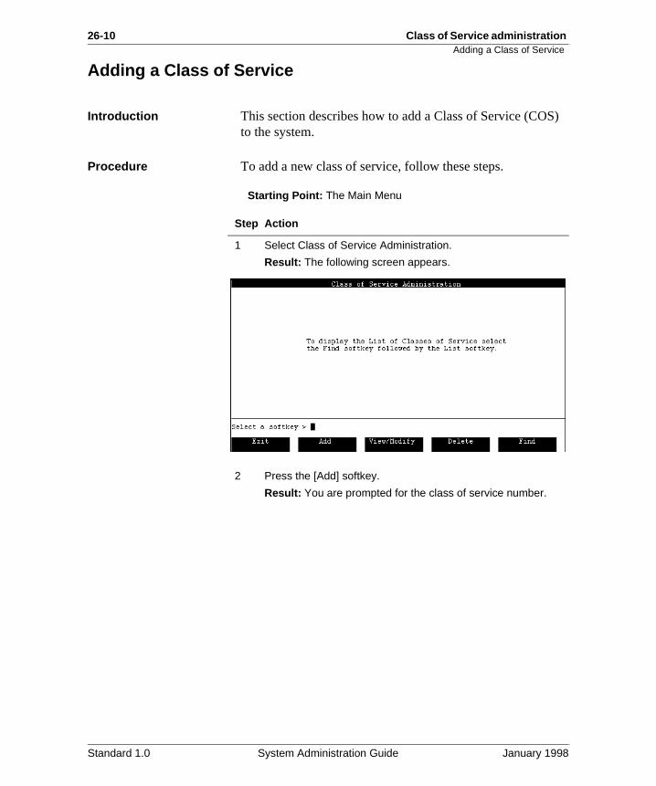
26-10 Class of Service administration Adding a Class of Service
S)
Adding a Class of Service
Introduction This section describes how to add a Class of Service (COto the system.
Procedure To add a new class of service, follow these steps.
Starting Point: The Main Menu
Step Action
1 Select Class of Service Administration.
Result: The following screen appears.
2 Press the [Add] softkey.
Result: You are prompted for the class of service number.
Standard 1.0 System Administration Guide January 1998
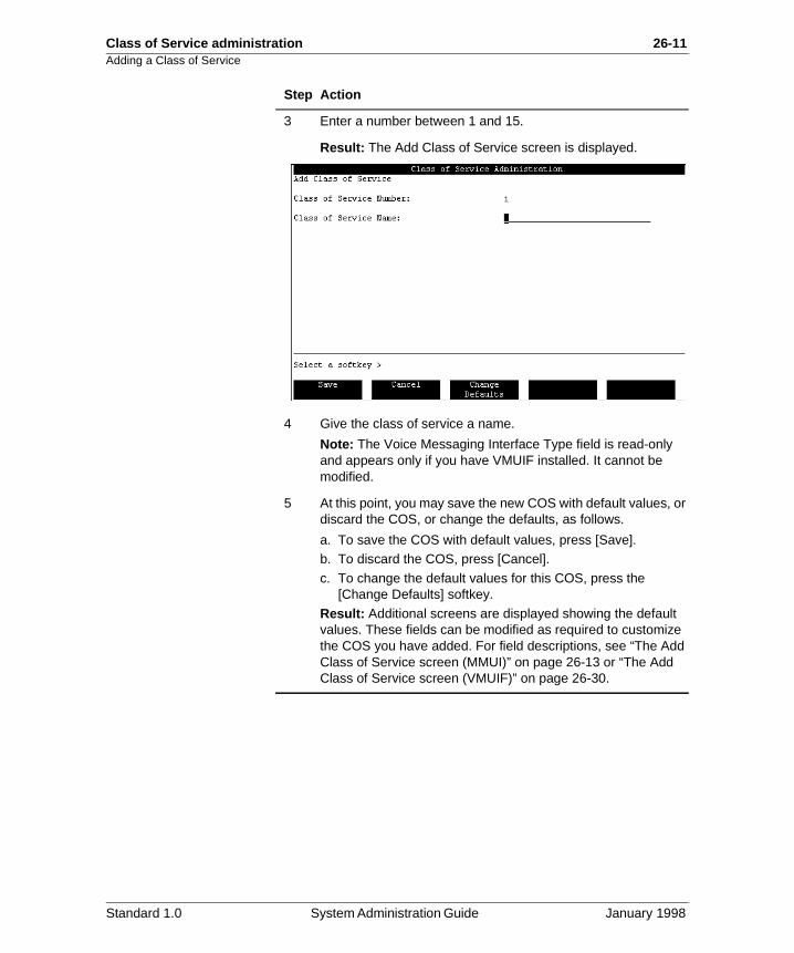
Class of Service administration 26-11Adding a Class of Service
3 Enter a number between 1 and 15.
Result: The Add Class of Service screen is displayed.
4 Give the class of service a name.
Note: The Voice Messaging Interface Type field is read-only and appears only if you have VMUIF installed. It cannot be modified.
5 At this point, you may save the new COS with default values, or discard the COS, or change the defaults, as follows.
a. To save the COS with default values, press [Save].b. To discard the COS, press [Cancel].
c. To change the default values for this COS, press the [Change Defaults] softkey.
Result: Additional screens are displayed showing the default values. These fields can be modified as required to customize the COS you have added. For field descriptions, see “The Add Class of Service screen (MMUI)” on page 26-13 or “The Add Class of Service screen (VMUIF)” on page 26-30.
Step Action
Standard 1.0 System Administration Guide January 1998
26-12 Class of Service administration Adding a Class of Service
ice one n
lse:
eted
not
er ser
as
a
Adding a class of service for users with dial pulse sets
If the system was installed with the VMUIF interface and there is a possibility that some users will have dial pulse phone sets, then at least one of the VMUIF classes of servthat you add should support users who have dial pulse phsets. The following fields in the Add Class of Service screemust be configured as indicated in order to support dial pu
• Dial Pulse support: Yes
• Auto Logon: Yes
• Skip to First New Message: Yes
• Read Message Retention: This must be a value other than zero so that read messages are automatically delon a regular basis (such as every seven days).
A dial pulse user can also record a personal greeting by calling a greeting change service. If a personal greeting is recorded, the default system greeting is played.
If a dial pulse user logs in from a phone other than his or hhome phone, a mailbox and password are required. (The umust, therefore, call in from a phone with touch-tone support.) However, once logged on, the mailbox operatesif it was accessed from a household phone (no further commands are required). However, if the user does enter DTMF command, the call reverts to the standard DTMF interface.
Standard 1.0 System Administration Guide January 1998
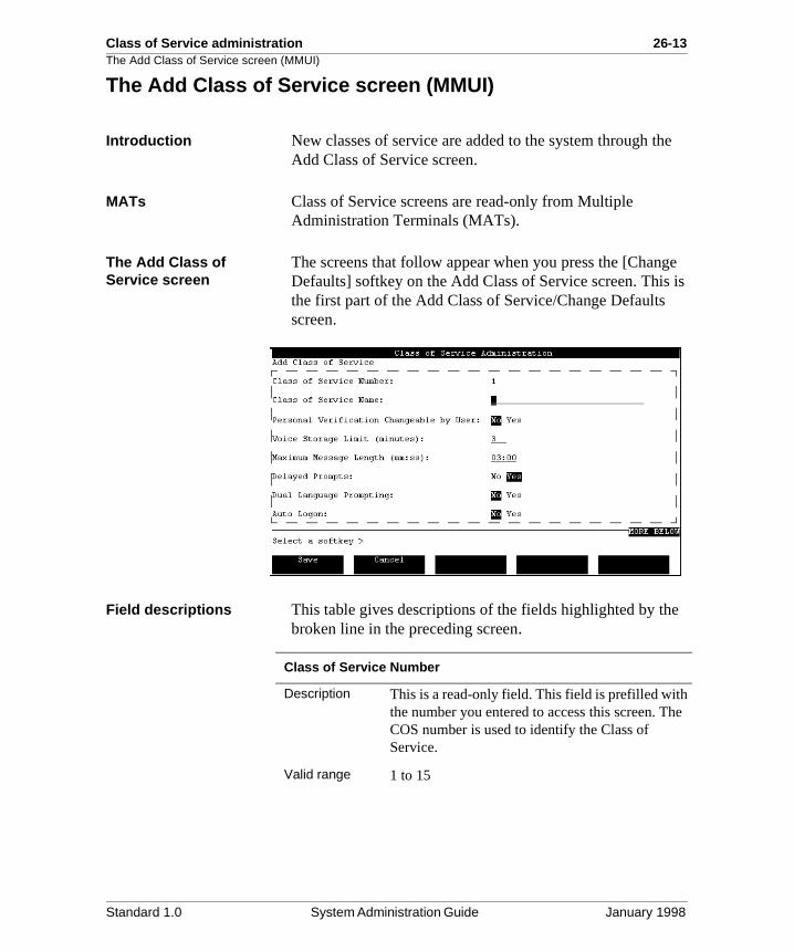
Class of Service administration 26-13The Add Class of Service screen (MMUI)
e
ge is
e
he
The Add Class of Service screen (MMUI)
Introduction New classes of service are added to the system through thAdd Class of Service screen.
MATs Class of Service screens are read-only from Multiple Administration Terminals (MATs).
The Add Class of Service screen
The screens that follow appear when you press the [ChanDefaults] softkey on the Add Class of Service screen. Thisthe first part of the Add Class of Service/Change Defaults screen.
Field descriptions This table gives descriptions of the fields highlighted by thbroken line in the preceding screen.
Class of Service Number
Description This is a read-only field. This field is prefilled withthe number you entered to access this screen. TCOS number is used to identify the Class of Service.
Valid range 1 to 15
Standard 1.0 System Administration Guide January 1998
26-14 Class of Service administration The Add Class of Service screen (MMUI)
d d
e
y
Class of Service Name
Description This is the name of the class of service. This fielis mandatory. The COS definition cannot be saveif this field is blank.
Maximum length
The COS name can be up to 30 characters in length.
Valid characters
All characters are valid with the exception of “+”,“_”, or “?”, which are invalid.
Personal Verification Changeable by User
Description (MMUI only) If this field is set to No, only the administrator is allowed to record personal verifications for users belonging to the COS. If thfield is set to Yes, users can record their own personal verifications from their telephone sets. The latter option is generally desirable since callers prefer to hear the voice of the person theare calling.
Default The default value is No.
Standard 1.0 System Administration Guide January 1998
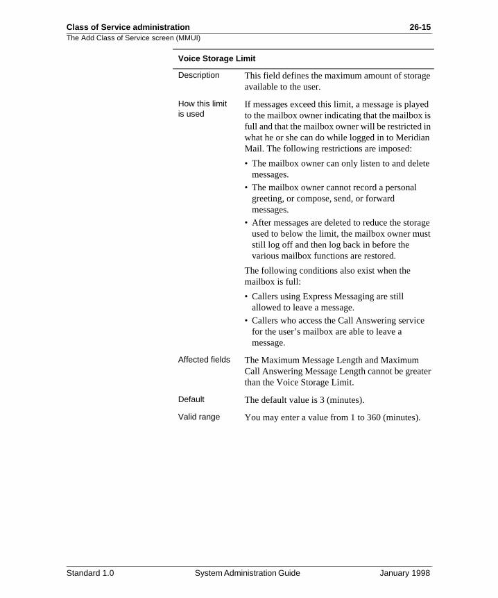
Class of Service administration 26-15The Add Class of Service screen (MMUI)
e
ed s
n
e
ge t
ter
Voice Storage Limit
Description This field defines the maximum amount of storagavailable to the user.
How this limit is used
If messages exceed this limit, a message is playto the mailbox owner indicating that the mailbox ifull and that the mailbox owner will be restricted inwhat he or she can do while logged in to MeridiaMail. The following restrictions are imposed:
• The mailbox owner can only listen to and deletmessages.
• The mailbox owner cannot record a personal greeting, or compose, send, or forward messages.
• After messages are deleted to reduce the storaused to below the limit, the mailbox owner musstill log off and then log back in before the various mailbox functions are restored.
The following conditions also exist when the mailbox is full:
• Callers using Express Messaging are still allowed to leave a message.
• Callers who access the Call Answering servicefor the user’s mailbox are able to leave a message.
Affected fields The Maximum Message Length and Maximum Call Answering Message Length cannot be greathan the Voice Storage Limit.
Default The default value is 3 (minutes).
Valid range You may enter a value from 1 to 360 (minutes).
Standard 1.0 System Administration Guide January 1998
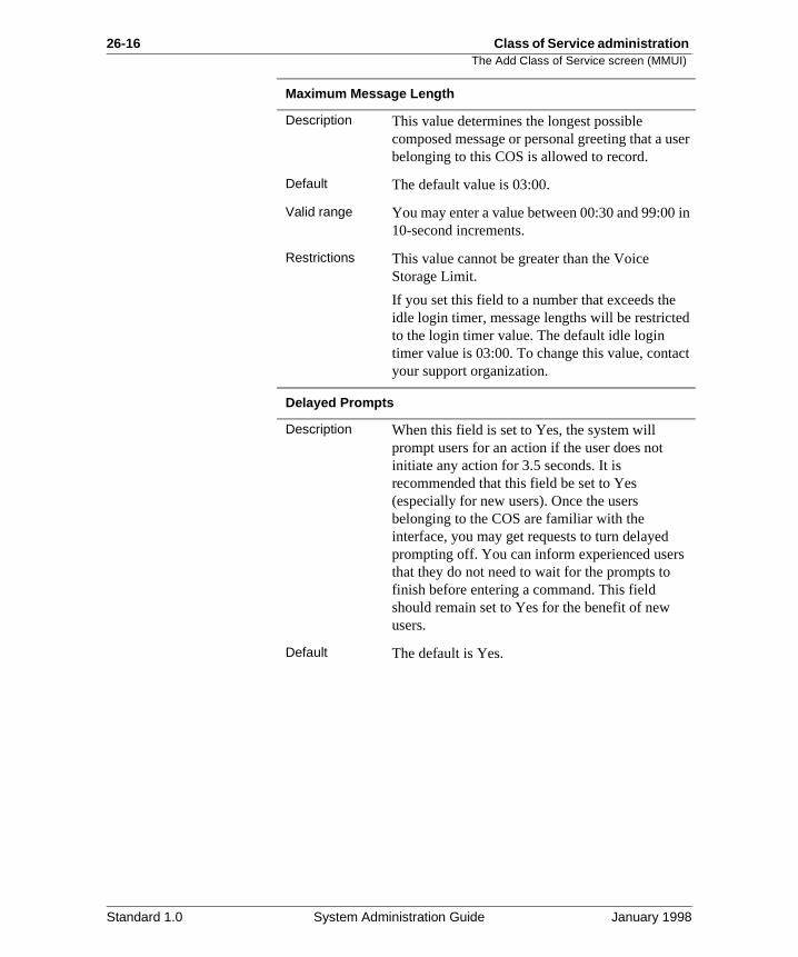
26-16 Class of Service administration The Add Class of Service screen (MMUI)
ser
in
d
ct
Maximum Message Length
Description This value determines the longest possible composed message or personal greeting that a ubelonging to this COS is allowed to record.
Default The default value is 03:00.
Valid range You may enter a value between 00:30 and 99:0010-second increments.
Restrictions This value cannot be greater than the Voice Storage Limit.
If you set this field to a number that exceeds theidle login timer, message lengths will be restricteto the login timer value. The default idle login timer value is 03:00. To change this value, contayour support organization.
Delayed Prompts
Description When this field is set to Yes, the system will prompt users for an action if the user does not initiate any action for 3.5 seconds. It is recommended that this field be set to Yes (especially for new users). Once the users belonging to the COS are familiar with the interface, you may get requests to turn delayed prompting off. You can inform experienced usersthat they do not need to wait for the prompts to finish before entering a command. This field should remain set to Yes for the benefit of new users.
Default The default is Yes.
Standard 1.0 System Administration Guide January 1998
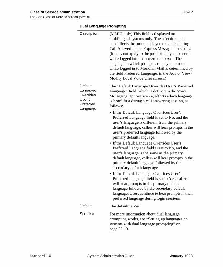
Class of Service administration 26-17The Add Class of Service screen (MMUI)
s.
/
d
ge
e
e
eir
Dual Language Prompting
Description (MMUI only) This field is displayed on multilingual systems only. The selection made here affects the prompts played to callers duringCall Answering and Express Messaging session(It does not apply to the prompts played to userswhile logged into their own mailboxes. The language in which prompts are played to users while logged in to Meridian Mail is determined bythe field Preferred Language, in the Add or ViewModify Local Voice User screen.)
Default Language Overrides User’s Preferred Language
The “Default Language Overrides User’s PreferreLanguage” field, which is defined in the Voice Messaging Options screen, affects which languais heard first during a call answering session, asfollows:
• If the Default Language Overrides User’s Preferred Language field is set to No, and the user’s language is different from the primary default language, callers will hear prompts in thuser’s preferred language followed by the primary default language.
• If the Default Language Overrides User’s Preferred Language field is set to No, and the user’s language is the same as the primary default language, callers will hear prompts in thprimary default language followed by the secondary default language.
• If the Default Language Overrides User’s Preferred Language field is set to Yes, callers will hear prompts in the primary default language followed by the secondary default language. Users continue to hear prompts in thpreferred language during login sessions.
Default The default is Yes.
See also For more information about dual language prompting works, see “Setting up languages on systems with dual language prompting” on page 20-19.
Standard 1.0 System Administration Guide January 1998
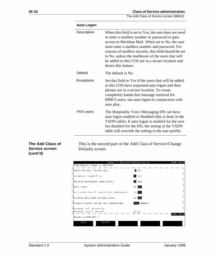
26-18 Class of Service administration The Add Class of Service screen (MMUI)
e
ed
r et d
d
e r
The Add Class of Service screen (cont’d)
This is the second part of the Add Class of Service/ChangDefaults screen.
Auto Logon
Description When this field is set to Yes, the user does not neto enter a mailbox number or password to gain access to Meridian Mail. When set to No, the usemust enter a mailbox number and password. Forreasons of mailbox security, this field should be sto No, unless the mailboxes of the users that willbe added to this COS are in a secure location andesire this feature.
Default The default is No.
Exceptions Set this field to Yes if the users that will be addeto this COS have requested auto logon and theirphones are in a secure location. To create completely hands-free message retrieval for MMUI users, use auto logon in conjunction with auto play.
HVS users The Hospitality Voice Messaging DN can have auto logon enabled or disabled (this is done in thVSDN table). If auto logon is enabled for the usebut disabled for the DN, the setting in the VSDN table will override the setting in the user profile.
Standard 1.0 System Administration Guide January 1998
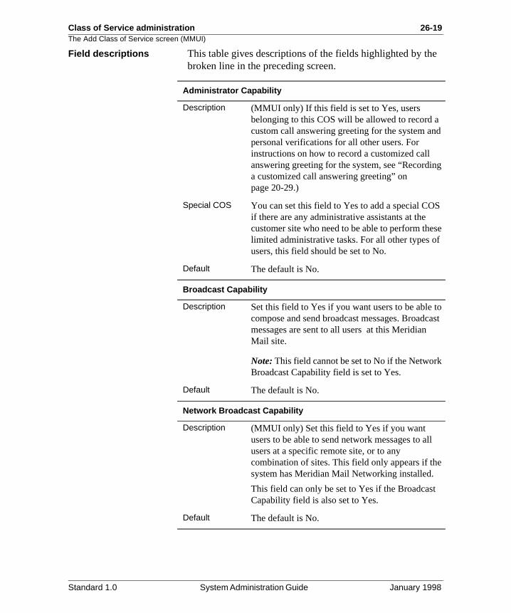
Class of Service administration 26-19The Add Class of Service screen (MMUI)
e
d
g
S
se f
to ast
ll
e
Field descriptions This table gives descriptions of the fields highlighted by thbroken line in the preceding screen.
Administrator Capability
Description (MMUI only) If this field is set to Yes, users belonging to this COS will be allowed to record acustom call answering greeting for the system anpersonal verifications for all other users. For instructions on how to record a customized call answering greeting for the system, see “Recordina customized call answering greeting” on page 20-29.)
Special COS You can set this field to Yes to add a special COif there are any administrative assistants at the customer site who need to be able to perform thelimited administrative tasks. For all other types ousers, this field should be set to No.
Default The default is No.
Broadcast Capability
Description Set this field to Yes if you want users to be able compose and send broadcast messages. Broadcmessages are sent to all users at this Meridian Mail site.
Note: This field cannot be set to No if the NetworkBroadcast Capability field is set to Yes.
Default The default is No.
Network Broadcast Capability
Description (MMUI only) Set this field to Yes if you want users to be able to send network messages to ausers at a specific remote site, or to any combination of sites. This field only appears if thsystem has Meridian Mail Networking installed.
This field can only be set to Yes if the BroadcastCapability field is also set to Yes.
Default The default is No.
Standard 1.0 System Administration Guide January 1998
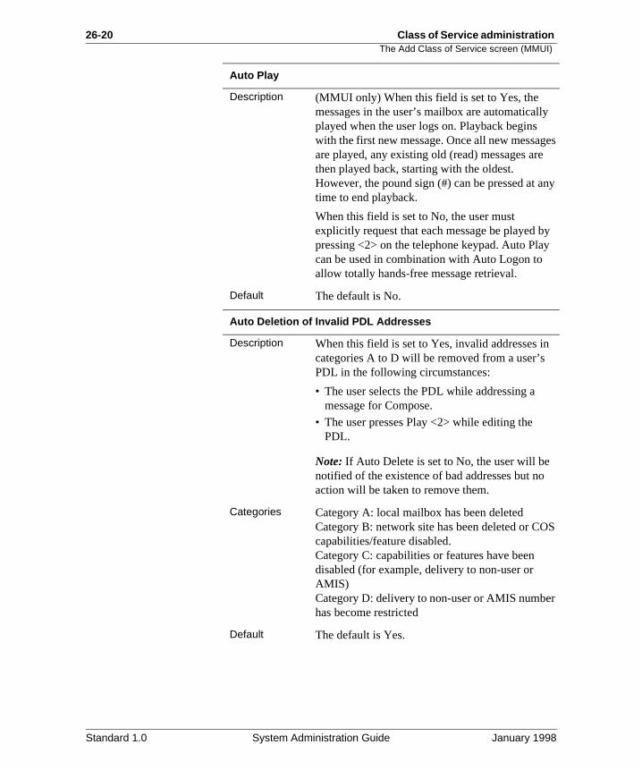
26-20 Class of Service administration The Add Class of Service screen (MMUI)
y
es
ny
y y
S
r
Auto Play
Description (MMUI only) When this field is set to Yes, the messages in the user’s mailbox are automaticallplayed when the user logs on. Playback begins with the first new message. Once all new messagare played, any existing old (read) messages arethen played back, starting with the oldest. However, the pound sign (#) can be pressed at atime to end playback.
When this field is set to No, the user must explicitly request that each message be played bpressing <2> on the telephone keypad. Auto Placan be used in combination with Auto Logon to allow totally hands-free message retrieval.
Default The default is No.
Auto Deletion of Invalid PDL Addresses
Description When this field is set to Yes, invalid addresses incategories A to D will be removed from a user’s PDL in the following circumstances:
• The user selects the PDL while addressing a message for Compose.
• The user presses Play <2> while editing the PDL.
Note: If Auto Delete is set to No, the user will be notified of the existence of bad addresses but noaction will be taken to remove them.
Categories Category A: local mailbox has been deletedCategory B: network site has been deleted or COcapabilities/feature disabled.Category C: capabilities or features have been disabled (for example, delivery to non-user or AMIS)Category D: delivery to non-user or AMIS numbehas become restricted
Default The default is Yes.
Standard 1.0 System Administration Guide January 1998
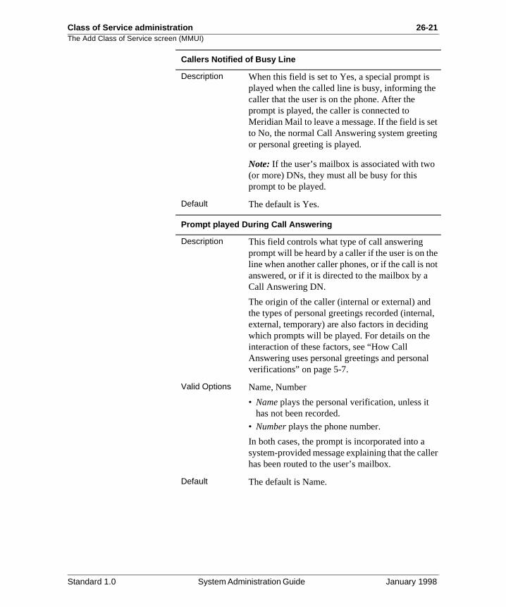
Class of Service administration 26-21The Add Class of Service screen (MMUI)
et g
e ot
l,
l
ler
Callers Notified of Busy Line
Description When this field is set to Yes, a special prompt is played when the called line is busy, informing thecaller that the user is on the phone. After the prompt is played, the caller is connected to Meridian Mail to leave a message. If the field is sto No, the normal Call Answering system greetinor personal greeting is played.
Note: If the user’s mailbox is associated with two(or more) DNs, they must all be busy for this prompt to be played.
Default The default is Yes.
Prompt played During Call Answering
Description This field controls what type of call answering prompt will be heard by a caller if the user is on thline when another caller phones, or if the call is nanswered, or if it is directed to the mailbox by a Call Answering DN.
The origin of the caller (internal or external) and the types of personal greetings recorded (internaexternal, temporary) are also factors in deciding which prompts will be played. For details on the interaction of these factors, see “How Call Answering uses personal greetings and personaverifications” on page 5-7.
Valid Options Name, Number
• Name plays the personal verification, unless it has not been recorded.
• Number plays the phone number.
In both cases, the prompt is incorporated into a system-provided message explaining that the calhas been routed to the user’s mailbox.
Default The default is Name.
Standard 1.0 System Administration Guide January 1998
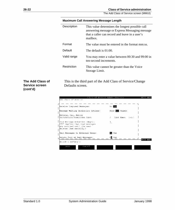
26-22 Class of Service administration The Add Class of Service screen (MMUI)
age
in
The Add Class of Service screen (cont’d)
This is the third part of the Add Class of Service/Change Defaults screen.
Maximum Call Answering Message Length
Description This value determines the longest possible call answering message or Express Messaging messthat a caller can record and leave in a user’s mailbox.
Format The value must be entered in the format mm:ss.
Default The default is 01:00.
Valid range You may enter a value between 00:30 and 99:00ten-second increments.
Restriction This value cannot be greater than the Voice Storage Limit.
Standard 1.0 System Administration Guide January 1998
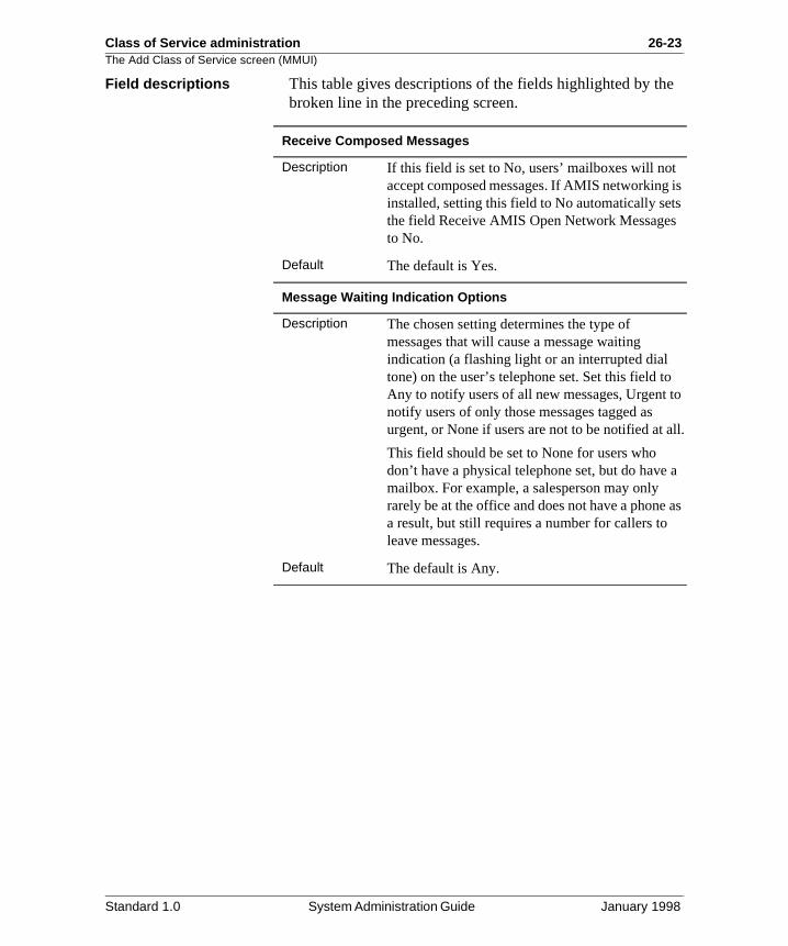
Class of Service administration 26-23The Add Class of Service screen (MMUI)
e
is s
to
ll.
a
as
Field descriptions This table gives descriptions of the fields highlighted by thbroken line in the preceding screen.
Receive Composed Messages
Description If this field is set to No, users’ mailboxes will not accept composed messages. If AMIS networkinginstalled, setting this field to No automatically setthe field Receive AMIS Open Network Messagesto No.
Default The default is Yes.
Message Waiting Indication Options
Description The chosen setting determines the type of messages that will cause a message waiting indication (a flashing light or an interrupted dial tone) on the user’s telephone set. Set this field toAny to notify users of all new messages, Urgent notify users of only those messages tagged as urgent, or None if users are not to be notified at a
This field should be set to None for users who don’t have a physical telephone set, but do havemailbox. For example, a salesperson may only rarely be at the office and does not have a phonea result, but still requires a number for callers to leave messages.
Default The default is Any.
Standard 1.0 System Administration Guide January 1998
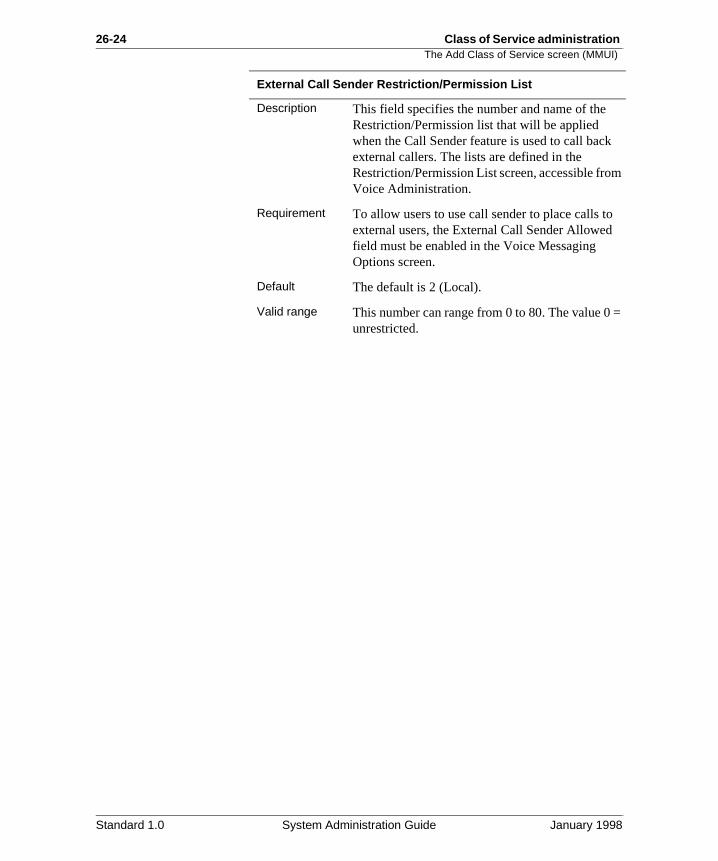
26-24 Class of Service administration The Add Class of Service screen (MMUI)
m
=
External Call Sender Restriction/Permission List
Description This field specifies the number and name of the Restriction/Permission list that will be applied when the Call Sender feature is used to call backexternal callers. The lists are defined in the Restriction/Permission List screen, accessible froVoice Administration.
Requirement To allow users to use call sender to place calls toexternal users, the External Call Sender Allowedfield must be enabled in the Voice Messaging Options screen.
Default The default is 2 (Local).
Valid range This number can range from 0 to 80. The value 0unrestricted.
Standard 1.0 System Administration Guide January 1998
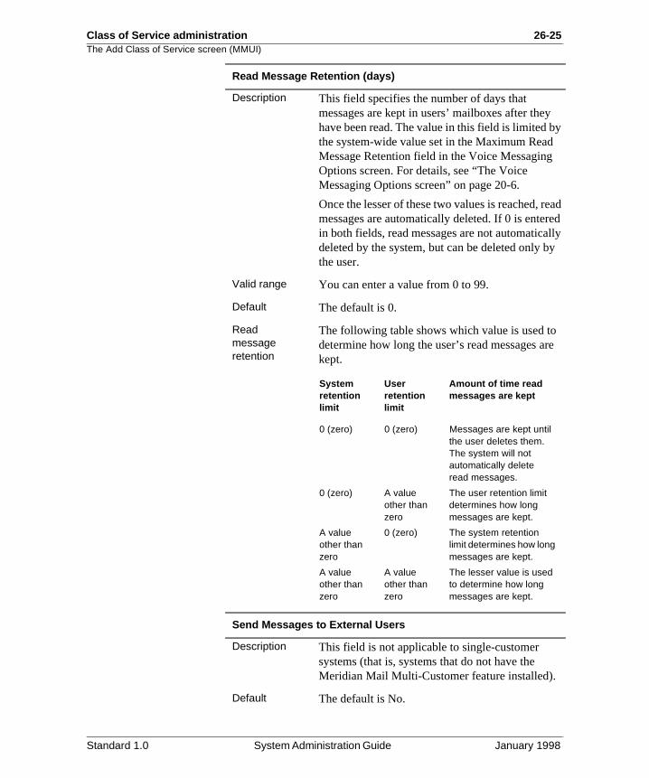
Class of Service administration 26-25The Add Class of Service screen (MMUI)
y
ead ed lly y
re
Read Message Retention (days)
Description This field specifies the number of days that messages are kept in users’ mailboxes after theyhave been read. The value in this field is limited bthe system-wide value set in the Maximum ReadMessage Retention field in the Voice MessagingOptions screen. For details, see “The Voice Messaging Options screen” on page 20-6.
Once the lesser of these two values is reached, rmessages are automatically deleted. If 0 is enterin both fields, read messages are not automaticadeleted by the system, but can be deleted only bthe user.
Valid range You can enter a value from 0 to 99.
Default The default is 0.
Read message retention
The following table shows which value is used todetermine how long the user’s read messages akept.
Send Messages to External Users
Description This field is not applicable to single-customer systems (that is, systems that do not have the Meridian Mail Multi-Customer feature installed).
Default The default is No.
System retention limit
User retention limit
Amount of time read messages are kept
0 (zero) 0 (zero) Messages are kept until the user deletes them. The system will not automatically delete read messages.
0 (zero) A value other than zero
The user retention limit determines how long messages are kept.
A value other than zero
0 (zero) The system retention limit determines how long messages are kept.
A value other than zero
A value other than zero
The lesser value is used to determine how long messages are kept.
Standard 1.0 System Administration Guide January 1998
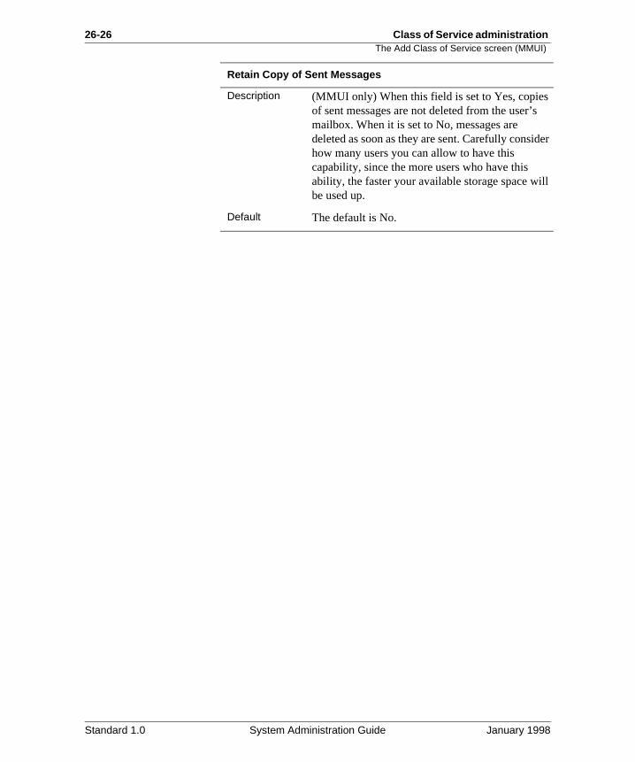
26-26 Class of Service administration The Add Class of Service screen (MMUI)
der
ill
Retain Copy of Sent Messages
Description (MMUI only) When this field is set to Yes, copiesof sent messages are not deleted from the user’smailbox. When it is set to No, messages are deleted as soon as they are sent. Carefully consihow many users you can allow to have this capability, since the more users who have this ability, the faster your available storage space wbe used up.
Default The default is No.
Standard 1.0 System Administration Guide January 1998
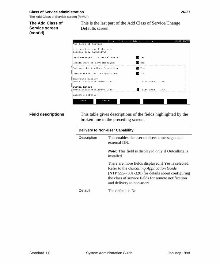
Class of Service administration 26-27The Add Class of Service screen (MMUI)
e
d.
The Add Class of Service screen (cont’d)
This is the last part of the Add Class of Service/Change Defaults screen.
Field descriptions This table gives descriptions of the fields highlighted by thbroken line in the preceding screen.
Delivery to Non-User Capability
Description This enables the user to direct a message to an external DN.
Note: This field is displayed only if Outcalling is installed.
There are more fields displayed if Yes is selecteRefer to the Outcalling Application Guide (NTP 555-7001-320) for details about configuringthe class of service fields for remote notification and delivery to non-users.
Default The default is No.
Standard 1.0 System Administration Guide January 1998
26-28 Class of Service administration The Add Class of Service screen (MMUI)
a
d.
to
d
Remote Notification Capability
Description This field permits the user to receive notification of messages, automatically, to an external DN orpaging device.
Note: This field is displayed only if Outcalling is installed.
There are more fields displayed if Yes is selecteRefer to the Outcalling Application Guide (NTP 555-7001-320) for details about configuringthe class of service fields for remote notification and delivery to non-users.
Default The default is No.
Receive AMIS Open Network Messages
Description This field permits the users to receive messagesfrom users at the AMIS Open Network sites.
Note: This field is displayed only if the AMIS Networking feature Network is installed.
Default The default value is No.
Compose/Send AMIS Open Network Messages
Description This field determines whether users are allowed compose and send messages to AMIS Open Network users. If this field is set to Yes, the AMISOpen Network Restriction/Permission List is displayed.
Note: This field is displayed only if the AMIS Networking feature is installed.
Valid options Yes, No
No indicates that users cannot compose and senAMIS open network messages. However, users can still compose and send AMIS messages to remote users that are located at virtual nodes within a Meridian Network.
Default The default value is No.
Standard 1.0 System Administration Guide January 1998
Class of Service administration 26-29The Add Class of Service screen (MMUI)
er
n .
=
s in
n .
=
a a e
t t
m
=
AMIS Open Network Restriction/Permission List
Description This field gives the number and name of the Restriction/Permission list that applies when a ussends an AMIS Open Network message.
The lists are defined in the Restriction/PermissioList screen, accessible from Voice Administration
Valid range This number can range from 0 to 80. The value 0unrestricted.
Default The default is 2 (Local).
Extension Dialing Restriction/Permission List
Description (MMUI only) This field gives the number and name of the Restriction/Permission list that appliewhen a user dials a phone number while logged to his or her mailbox (known as Thru-dialing).
The lists are defined in the Restriction/PermissioList screen, accessible from Voice Administration
Valid range This number can range from 0 to 80. The value 0unrestricted.
Default The default is 2 (Local).
Custom Revert Restriction/Permission List
Description The custom revert DN is the extension to which caller is passed when the caller presses 0 duringMeridian Mail session. Since users can customizthis DN from their telephone sets you must determine which dialing codes you want to restric(or explicitly permit). For example, you may wanto ensure that users cannot revert callers to longdistance numbers.
This field gives the number and name of the Restriction/Permission list that is applied to the custom revert DN. The lists are defined in the Restriction/Permission List screen, accessible froVoice Administration.
Valid range This number can range from 0 to 80. The value 0unrestricted.
Default The default is 2 (Local).
Standard 1.0 System Administration Guide January 1998
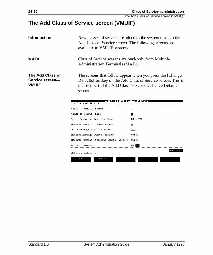
26-30 Class of Service administration The Add Class of Service screen (VMUIF)
e
ge is
The Add Class of Service screen (VMUIF)
Introduction New classes of service are added to the system through thAdd Class of Service screen. The following screens are available to VMUIF systems.
MATs Class of Service screens are read-only from Multiple Administration Terminals (MATs).
The Add Class of Service screen—VMUIF
The screens that follow appear when you press the [ChanDefaults] softkey on the Add Class of Service screen. Thisthe first part of the Add Class of Service/Change Defaults screen.
Standard 1.0 System Administration Guide January 1998
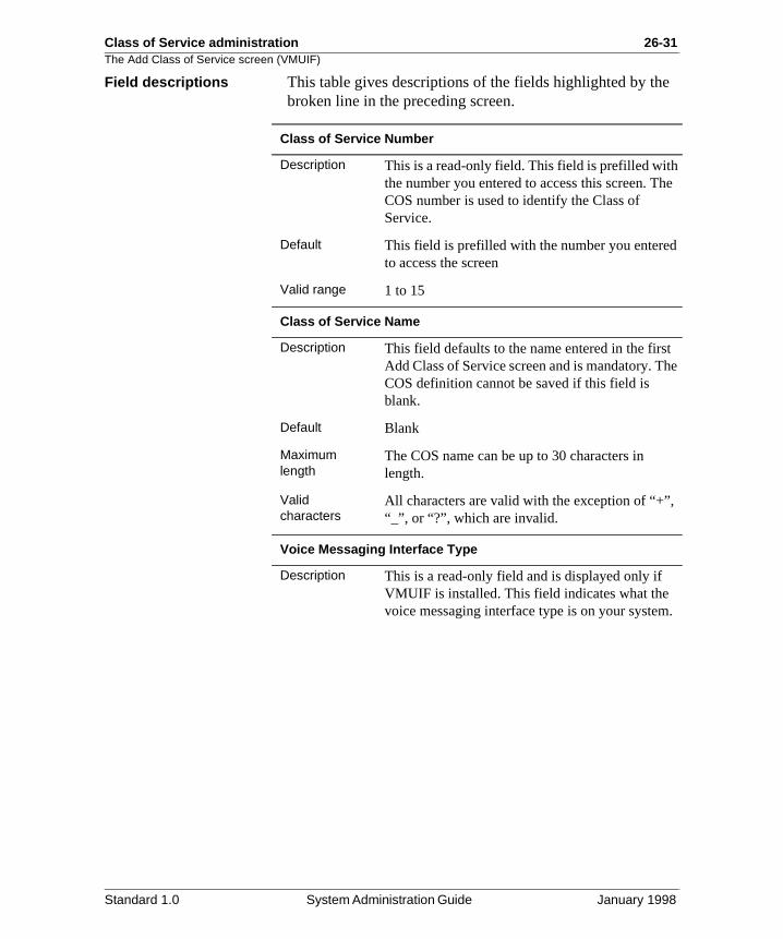
Class of Service administration 26-31The Add Class of Service screen (VMUIF)
e
he
t he
.
Field descriptions This table gives descriptions of the fields highlighted by thbroken line in the preceding screen.
Class of Service Number
Description This is a read-only field. This field is prefilled withthe number you entered to access this screen. TCOS number is used to identify the Class of Service.
Default This field is prefilled with the number you enteredto access the screen
Valid range 1 to 15
Class of Service Name
Description This field defaults to the name entered in the firsAdd Class of Service screen and is mandatory. TCOS definition cannot be saved if this field is blank.
Default Blank
Maximum length
The COS name can be up to 30 characters in length.
Valid characters
All characters are valid with the exception of “+”,“_”, or “?”, which are invalid.
Voice Messaging Interface Type
Description This is a read-only field and is displayed only if VMUIF is installed. This field indicates what the voice messaging interface type is on your system
Standard 1.0 System Administration Guide January 1998
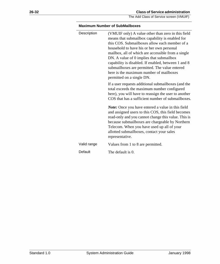
26-32 Class of Service administration The Add Class of Service screen (VMUIF)
8
he
er s.
es is rn
Maximum Number of SubMailboxes
Description (VMUIF only) A value other than zero in this fieldmeans that submailbox capability is enabled for this COS. Submailboxes allow each member of ahousehold to have his or her own personal mailbox, all of which are accessible from a singleDN. A value of 0 implies that submailbox capability is disabled. If enabled, between 1 andsubmailboxes are permitted. The value entered here is the maximum number of mailboxes permitted on a single DN.
If a user requests additional submailboxes (and ttotal exceeds the maximum number configured here), you will have to reassign the user to anothCOS that has a sufficient number of submailboxe
Note: Once you have entered a value in this fieldand assigned users to this COS, this field becomread-only and you cannot change this value. Thisbecause submailboxes are chargeable by NortheTelecom. When you have used up all of your allotted submailboxes, contact your sales representative.
Valid range Values from 1 to 8 are permitted.
Default The default is 0.
Standard 1.0 System Administration Guide January 1998
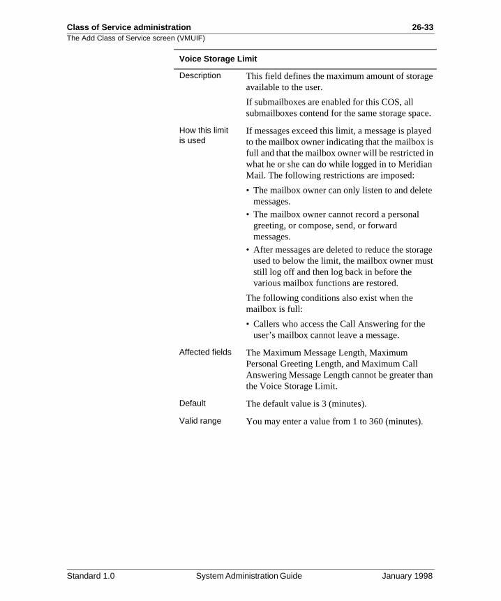
Class of Service administration 26-33The Add Class of Service screen (VMUIF)
e
ce.
ed s
n
e
ge t
an
Voice Storage Limit
Description This field defines the maximum amount of storagavailable to the user.
If submailboxes are enabled for this COS, all submailboxes contend for the same storage spa
How this limit is used
If messages exceed this limit, a message is playto the mailbox owner indicating that the mailbox ifull and that the mailbox owner will be restricted inwhat he or she can do while logged in to MeridiaMail. The following restrictions are imposed:
• The mailbox owner can only listen to and deletmessages.
• The mailbox owner cannot record a personal greeting, or compose, send, or forward messages.
• After messages are deleted to reduce the storaused to below the limit, the mailbox owner musstill log off and then log back in before the various mailbox functions are restored.
The following conditions also exist when the mailbox is full:
• Callers who access the Call Answering for the user’s mailbox cannot leave a message.
Affected fields The Maximum Message Length, Maximum Personal Greeting Length, and Maximum Call Answering Message Length cannot be greater ththe Voice Storage Limit.
Default The default value is 3 (minutes).
Valid range You may enter a value from 1 to 360 (minutes).
Standard 1.0 System Administration Guide January 1998
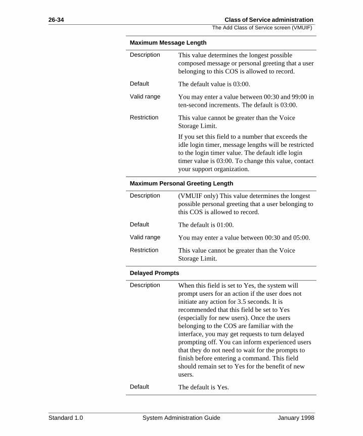
26-34 Class of Service administration The Add Class of Service screen (VMUIF)
ser
in
d
ct
to
.
Maximum Message Length
Description This value determines the longest possible composed message or personal greeting that a ubelonging to this COS is allowed to record.
Default The default value is 03:00.
Valid range You may enter a value between 00:30 and 99:00ten-second increments. The default is 03:00.
Restriction This value cannot be greater than the Voice Storage Limit.
If you set this field to a number that exceeds theidle login timer, message lengths will be restricteto the login timer value. The default idle login timer value is 03:00. To change this value, contayour support organization.
Maximum Personal Greeting Length
Description (VMUIF only) This value determines the longest possible personal greeting that a user belongingthis COS is allowed to record.
Default The default is 01:00.
Valid range You may enter a value between 00:30 and 05:00
Restriction This value cannot be greater than the Voice Storage Limit.
Delayed Prompts
Description When this field is set to Yes, the system will prompt users for an action if the user does not initiate any action for 3.5 seconds. It is recommended that this field be set to Yes (especially for new users). Once the users belonging to the COS are familiar with the interface, you may get requests to turn delayed prompting off. You can inform experienced usersthat they do not need to wait for the prompts to finish before entering a command. This field should remain set to Yes for the benefit of new users.
Default The default is Yes.
Standard 1.0 System Administration Guide January 1998
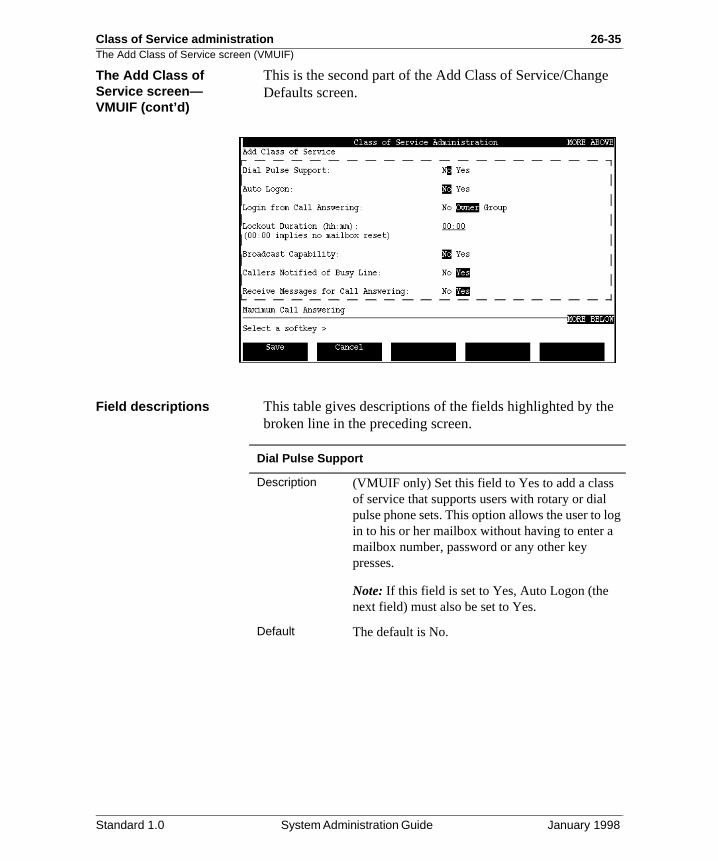
Class of Service administration 26-35The Add Class of Service screen (VMUIF)
e
e
og
The Add Class of Service screen—VMUIF (cont’d)
This is the second part of the Add Class of Service/ChangDefaults screen.
Field descriptions This table gives descriptions of the fields highlighted by thbroken line in the preceding screen.
Dial Pulse Support
Description (VMUIF only) Set this field to Yes to add a class of service that supports users with rotary or dial pulse phone sets. This option allows the user to lin to his or her mailbox without having to enter amailbox number, password or any other key presses.
Note: If this field is set to Yes, Auto Logon (the next field) must also be set to Yes.
Default The default is No.
Standard 1.0 System Administration Guide January 1998
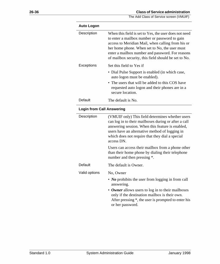
26-36 Class of Service administration The Add Class of Service screen (VMUIF)
ed
ns .
l ,
er
is
Auto Logon
Description When this field is set to Yes, the user does not neto enter a mailbox number or password to gain access to Meridian Mail, when calling from his orher home phone. When set to No, the user mustenter a mailbox number and password. For reasoof mailbox security, this field should be set to No
Exceptions Set this field to Yes if
• Dial Pulse Support is enabled (in which case, auto logon must be enabled).
• The users that will be added to this COS have requested auto logon and their phones are in asecure location.
Default The default is No.
Login from Call Answering
Description (VMUIF only) This field determines whether userscan log in to their mailboxes during or after a calanswering session. When this feature is enabledusers have an alternative method of logging in which does not require that they dial a special access DN.
Users can access their mailbox from a phone oththan their home phone by dialing their telephonenumber and then pressing *.
Default The default is Owner.
Valid options No, Owner
• No prohibits the user from logging in from call answering.
• Owner allows users to log in to their mailboxesonly if the destination mailbox is their own. After pressing *, the user is prompted to enter hor her password.
Standard 1.0 System Administration Guide January 1998
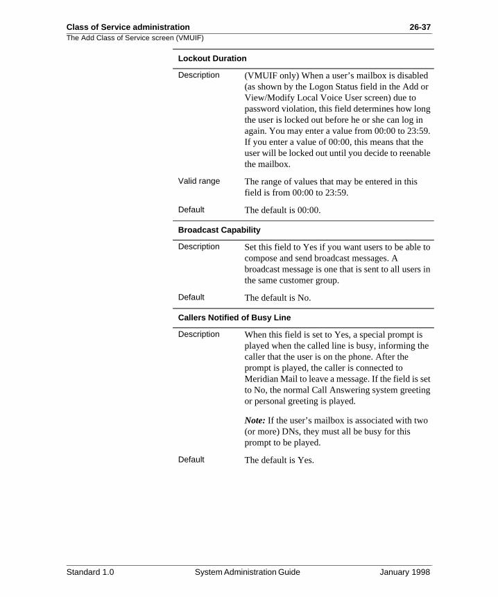
Class of Service administration 26-37The Add Class of Service screen (VMUIF)
r
g 9. le
to
s in
et g
Lockout Duration
Description (VMUIF only) When a user’s mailbox is disabled(as shown by the Logon Status field in the Add oView/Modify Local Voice User screen) due to password violation, this field determines how lonthe user is locked out before he or she can log inagain. You may enter a value from 00:00 to 23:5If you enter a value of 00:00, this means that theuser will be locked out until you decide to reenabthe mailbox.
Valid range The range of values that may be entered in this field is from 00:00 to 23:59.
Default The default is 00:00.
Broadcast Capability
Description Set this field to Yes if you want users to be able compose and send broadcast messages. A broadcast message is one that is sent to all userthe same customer group.
Default The default is No.
Callers Notified of Busy Line
Description When this field is set to Yes, a special prompt is played when the called line is busy, informing thecaller that the user is on the phone. After the prompt is played, the caller is connected to Meridian Mail to leave a message. If the field is sto No, the normal Call Answering system greetinor personal greeting is played.
Note: If the user’s mailbox is associated with two(or more) DNs, they must all be busy for this prompt to be played.
Default The default is Yes.
Standard 1.0 System Administration Guide January 1998
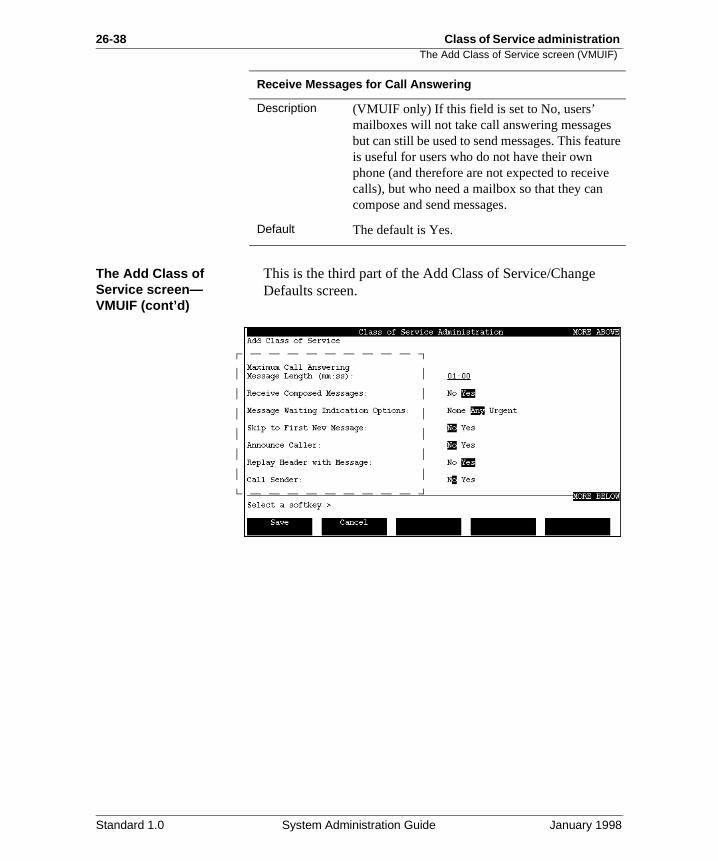
26-38 Class of Service administration The Add Class of Service screen (VMUIF)
ure
The Add Class of Service screen—VMUIF (cont’d)
This is the third part of the Add Class of Service/Change Defaults screen.
Receive Messages for Call Answering
Description (VMUIF only) If this field is set to No, users’ mailboxes will not take call answering messagesbut can still be used to send messages. This featis useful for users who do not have their own phone (and therefore are not expected to receivecalls), but who need a mailbox so that they can compose and send messages.
Default The default is Yes.
Standard 1.0 System Administration Guide January 1998
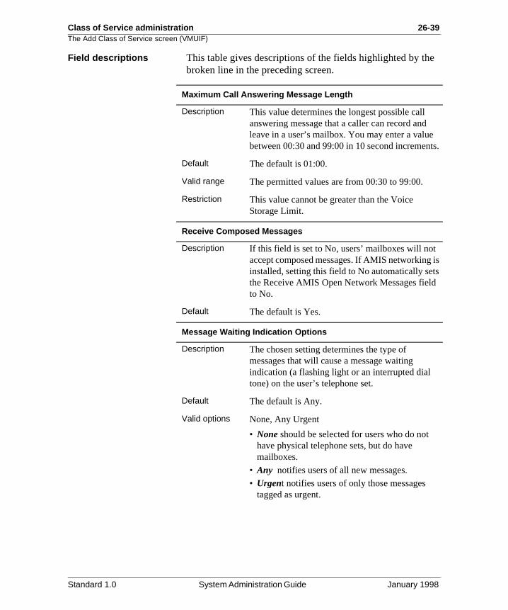
Class of Service administration 26-39The Add Class of Service screen (VMUIF)
e
ts.
is s
Field descriptions This table gives descriptions of the fields highlighted by thbroken line in the preceding screen.
Maximum Call Answering Message Length
Description This value determines the longest possible call answering message that a caller can record andleave in a user’s mailbox. You may enter a valuebetween 00:30 and 99:00 in 10 second incremen
Default The default is 01:00.
Valid range The permitted values are from 00:30 to 99:00.
Restriction This value cannot be greater than the Voice Storage Limit.
Receive Composed Messages
Description If this field is set to No, users’ mailboxes will not accept composed messages. If AMIS networkinginstalled, setting this field to No automatically setthe Receive AMIS Open Network Messages fieldto No.
Default The default is Yes.
Message Waiting Indication Options
Description The chosen setting determines the type of messages that will cause a message waiting indication (a flashing light or an interrupted dial tone) on the user’s telephone set.
Default The default is Any.
Valid options None, Any Urgent
• None should be selected for users who do not have physical telephone sets, but do have mailboxes.
• Any notifies users of all new messages.
• Urgent notifies users of only those messages tagged as urgent.
Standard 1.0 System Administration Guide January 1998
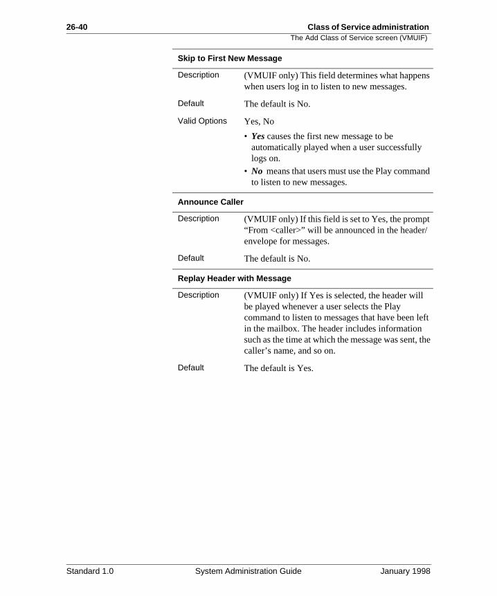
26-40 Class of Service administration The Add Class of Service screen (VMUIF)
nd
/
left
the
Skip to First New Message
Description (VMUIF only) This field determines what happenswhen users log in to listen to new messages.
Default The default is No.
Valid Options Yes, No
• Yes causes the first new message to be automatically played when a user successfullylogs on.
• No means that users must use the Play commato listen to new messages.
Announce Caller
Description (VMUIF only) If this field is set to Yes, the prompt“From <caller>” will be announced in the headerenvelope for messages.
Default The default is No.
Replay Header with Message
Description (VMUIF only) If Yes is selected, the header will be played whenever a user selects the Play command to listen to messages that have been in the mailbox. The header includes information such as the time at which the message was sent,caller’s name, and so on.
Default The default is Yes.
Standard 1.0 System Administration Guide January 1998
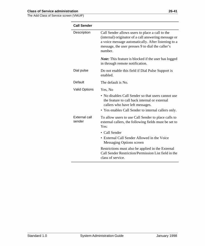
Class of Service administration 26-41The Add Class of Service screen (VMUIF)
or a
d
se
y.
to o
e
Call Sender
Description Call Sender allows users to place a call to the (internal) originator of a call answering message a voice message automatically. After listening tomessage, the user presses 9 to dial the caller’s number.
Note: This feature is blocked if the user has loggein through remote notification.
Dial pulse Do not enable this field if Dial Pulse Support is enabled.
Default The default is No.
Valid Options Yes, No
• No disables Call Sender so that users cannot uthe feature to call back internal or external callers who have left messages.
• Yes enables Call Sender to internal callers onl
External call sender
To allow users to use Call Sender to place calls external callers, the following fields must be set tYes:
• Call Sender
• External Call Sender Allowed in the Voice Messaging Options screen
Restrictions must also be applied in the ExternalCall Sender Restriction/Permission List field in thclass of service.
Standard 1.0 System Administration Guide January 1998
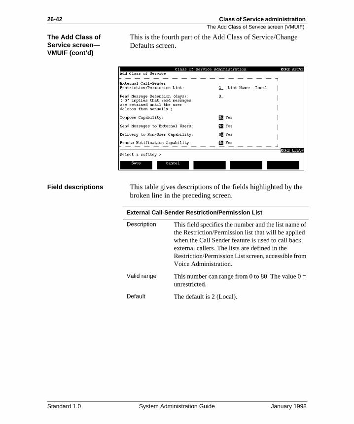
26-42 Class of Service administration The Add Class of Service screen (VMUIF)
e
of
m
=
The Add Class of Service screen—VMUIF (cont’d)
This is the fourth part of the Add Class of Service/ChangeDefaults screen.
Field descriptions This table gives descriptions of the fields highlighted by thbroken line in the preceding screen.
External Call-Sender Restriction/Permission List
Description This field specifies the number and the list name the Restriction/Permission list that will be appliedwhen the Call Sender feature is used to call backexternal callers. The lists are defined in the Restriction/Permission List screen, accessible froVoice Administration.
Valid range This number can range from 0 to 80. The value 0unrestricted.
Default The default is 2 (Local).
Standard 1.0 System Administration Guide January 1998
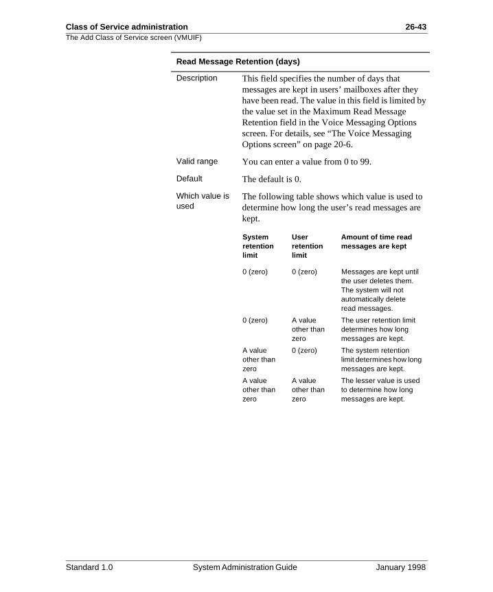
Class of Service administration 26-43The Add Class of Service screen (VMUIF)
y
re
Read Message Retention (days)
Description This field specifies the number of days that messages are kept in users’ mailboxes after theyhave been read. The value in this field is limited bthe value set in the Maximum Read Message Retention field in the Voice Messaging Options screen. For details, see “The Voice Messaging Options screen” on page 20-6.
Valid range You can enter a value from 0 to 99.
Default The default is 0.
Which value is used
The following table shows which value is used todetermine how long the user’s read messages akept.
System retention limit
User retention limit
Amount of time read messages are kept
0 (zero) 0 (zero) Messages are kept until the user deletes them. The system will not automatically delete read messages.
0 (zero) A value other than zero
The user retention limit determines how long messages are kept.
A value other than zero
0 (zero) The system retention limit determines how long messages are kept.
A value other than zero
A value other than zero
The lesser value is used to determine how long messages are kept.
Standard 1.0 System Administration Guide January 1998
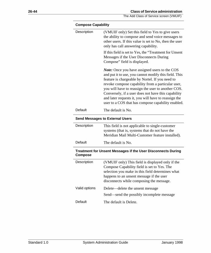
26-44 Class of Service administration The Add Class of Service screen (VMUIF)
to er
t
s
, S. y e led.
Compose Capability
Description (VMUIF only) Set this field to Yes to give users the ability to compose and send voice messagesother users. If this value is set to No, then the usonly has call answering capability.
If this field is set to Yes, the “Treatment for UnsenMessages if the User Disconnects During Compose” field is displayed.
Note: Once you have assigned users to the COSand put it to use, you cannot modify this field. Thifeature is chargeable by Nortel. If you need to revoke compose capability from a particular useryou will have to reassign the user to another COConversely, if a user does not have this capabilitand later requests it, you will have to reassign thuser to a COS that has compose capability enab
Default The default is No.
Send Messages to External Users
Description This field is not applicable to single-customer systems (that is, systems that do not have the Meridian Mail Multi-Customer feature installed).
Default The default is No.
Treatment for Unsent Messages if the User Disconnects During Compose
Description (VMUIF only) This field is displayed only if the Compose Capability field is set to Yes. The selection you make in this field determines what happens to an unsent message if the user disconnects while composing the message.
Valid options Delete—delete the unsent message
Send—send the possibly incomplete message
Default The default is Delete.
Standard 1.0 System Administration Guide January 1998
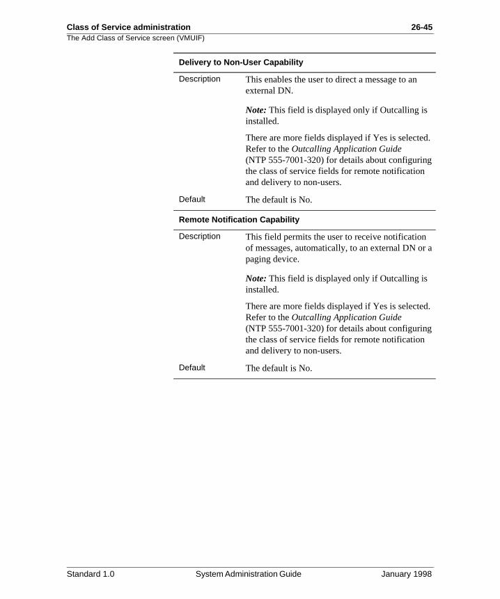
Class of Service administration 26-45The Add Class of Service screen (VMUIF)
d.
a
d.
Delivery to Non-User Capability
Description This enables the user to direct a message to an external DN.
Note: This field is displayed only if Outcalling is installed.
There are more fields displayed if Yes is selecteRefer to the Outcalling Application Guide (NTP 555-7001-320) for details about configuringthe class of service fields for remote notification and delivery to non-users.
Default The default is No.
Remote Notification Capability
Description This field permits the user to receive notification of messages, automatically, to an external DN orpaging device.
Note: This field is displayed only if Outcalling is installed.
There are more fields displayed if Yes is selecteRefer to the Outcalling Application Guide (NTP 555-7001-320) for details about configuringthe class of service fields for remote notification and delivery to non-users.
Default The default is No.
Standard 1.0 System Administration Guide January 1998

26-46 Class of Service administration The Add Class of Service screen (VMUIF)
e
The Add Class of Service screen—VMUIF (cont’d)
This is the fifth part of the Add Class of Service/Change Defaults screen.
Field descriptions This table gives descriptions of the fields highlighted by thbroken line in the preceding screen.
Receive AMIS Open Network Messages
Description This field permits the users to receive messagesfrom users at the AMIS Open Network sites.
Note: This field is displayed only if the AMIS Networking feature is installed.
Default The default value is No.
Standard 1.0 System Administration Guide January 1998
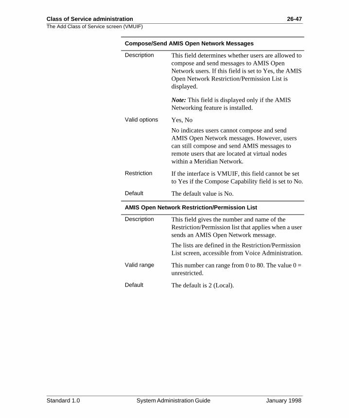
Class of Service administration 26-47The Add Class of Service screen (VMUIF)
to
o.
er
n .
=
Compose/Send AMIS Open Network Messages
Description This field determines whether users are allowed compose and send messages to AMIS Open Network users. If this field is set to Yes, the AMISOpen Network Restriction/Permission List is displayed.
Note: This field is displayed only if the AMIS Networking feature is installed.
Valid options Yes, No
No indicates users cannot compose and send AMIS Open Network messages. However, userscan still compose and send AMIS messages to remote users that are located at virtual nodes within a Meridian Network.
Restriction If the interface is VMUIF, this field cannot be setto Yes if the Compose Capability field is set to N
Default The default value is No.
AMIS Open Network Restriction/Permission List
Description This field gives the number and name of the Restriction/Permission list that applies when a ussends an AMIS Open Network message.
The lists are defined in the Restriction/PermissioList screen, accessible from Voice Administration
Valid range This number can range from 0 to 80. The value 0unrestricted.
Default The default is 2 (Local).
Standard 1.0 System Administration Guide January 1998
26-48 Class of Service administration The Add Class of Service screen (VMUIF)
a a
m
=
Custom Revert Restriction/Permission List
Description The custom revert DN is the extension to which caller is passed when the caller presses 0 duringMeridian Mail session.
This field gives the number and name of the Restriction/Permission list that is applied to the custom revert DN. These lists are defined in the Restriction/Permission List screen, accessible froVoice Administration.
Valid range This number can range from 0 to 80. The value 0unrestricted.
Default The default is 2 (Local).
Standard 1.0 System Administration Guide January 1998
Class of Service administration 26-49Assigning Classes of Service to the system
st
Assigning Classes of Service to the system
Introduction After creating (adding) a new Class of Service (COS), it mube made available for use. This is done in the General Options screen. See Chapter 13, “General options. ”
Standard 1.0 System Administration Guide January 1998
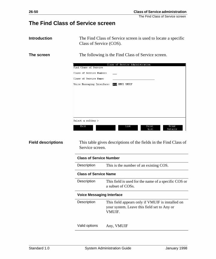
26-50 Class of Service administration The Find Class of Service screen
ific
of
or
The Find Class of Service screen
Introduction The Find Class of Service screen is used to locate a specClass of Service (COS).
The screen The following is the Find Class of Service screen.
Field descriptions This table gives descriptions of the fields in the Find ClassService screen.
Class of Service Number
Description This is the number of an existing COS.
Class of Service Name
Description This field is used for the name of a specific COS a subset of COSs.
Voice Messaging Interface
Description This field appears only if VMUIF is installed on your system. Leave this field set to Any or VMUIF.
Valid options Any, VMUIF
Standard 1.0 System Administration Guide January 1998
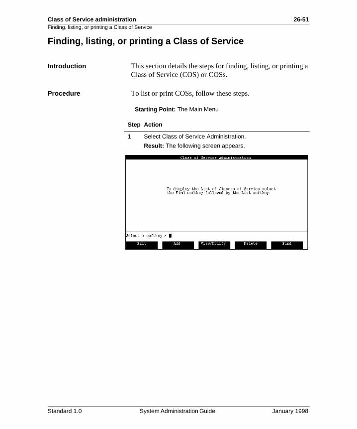
Class of Service administration 26-51Finding, listing, or printing a Class of Service
a
Finding, listing, or printing a Class of Service
Introduction This section details the steps for finding, listing, or printingClass of Service (COS) or COSs.
Procedure To list or print COSs, follow these steps.
Starting Point: The Main Menu
Step Action
1 Select Class of Service Administration.
Result: The following screen appears.
Standard 1.0 System Administration Guide January 1998
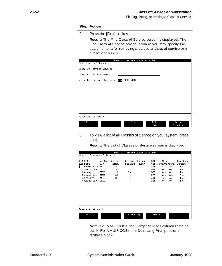
26-52 Class of Service administration Finding, listing, or printing a Class of Service
2 Press the [Find] softkey.
Result: The Find Class of Service screen is displayed. The Find Class of Service screen is where you may specify the search criteria for retrieving a particular class of service or a subset of classes.
3 To view a list of all Classes of Service on your system, press [List].
Result: The List of Classes of Service screen is displayed.
Note: For MMUI COSs, the Compose Msgs column remains blank. For VMUIF COSs, the Dual Lang Prompt column remains blank.
Step Action
Standard 1.0 System Administration Guide January 1998

Class of Service administration 26-53Finding, listing, or printing a Class of Service
4 To print a list of all Classes of Service on your system, press [Print List].
Result: The List of Classes of Service is printed.
5 To view or print a particular Class of Service or a specific group of Classes of Service, specify search criteria on the Find screen as follows.
6 To view or print the selected Classes of Service, press the appropriate softkey as follows.
Step Action
IF THEN
you want a specific COS and know its number
enter the number in the Class of Service Number field.
you want a specific COS and know its name
enter the name in the Class of Service Name field.
you want a group of COSs with similar names
enter the appropriate search pattern in the Class of Service Name field. (This pattern will consist of letters and wildcard characters.)
you want to find those COSs for a particular interface
specify either MMUI or VMUIF.
IF THEN
you want a list of the COSs according to the search criteria
press the [List] softkey.
you want to print the list of COSs
press the [Print List] softkey.
you want to print the details of a single COS
enter the COS number or name in the appropriate field and press the [Print Details] softkey.
Standard 1.0 System Administration Guide January 1998
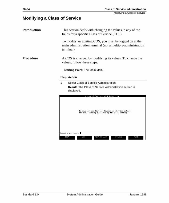
26-54 Class of Service administration Modifying a Class of Service
Modifying a Class of Service
Introduction This section deals with changing the values in any of the fields for a specific Class of Service (COS).
To modify an existing COS, you must be logged on at the main administration terminal (not a multiple-administrationterminal).
Procedure A COS is changed by modifying its values. To change thevalues, follow these steps.
Starting Point: The Main Menu.
Step Action
1 Select Class of Service Administration.
Result: The Class of Service Administration screen is displayed.
Standard 1.0 System Administration Guide January 1998
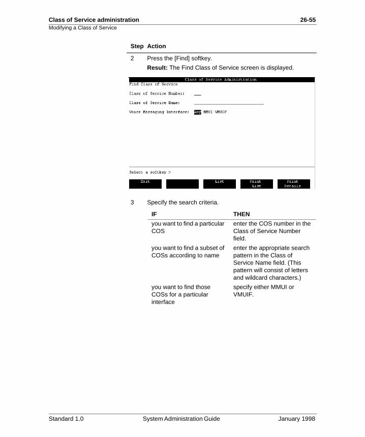
Class of Service administration 26-55Modifying a Class of Service
2 Press the [Find] softkey.
Result: The Find Class of Service screen is displayed.
3 Specify the search criteria.
Step Action
IF THEN
you want to find a particular COS
enter the COS number in the Class of Service Number field.
you want to find a subset of COSs according to name
enter the appropriate search pattern in the Class of Service Name field. (This pattern will consist of letters and wildcard characters.)
you want to find those COSs for a particular interface
specify either MMUI or VMUIF.
Standard 1.0 System Administration Guide January 1998
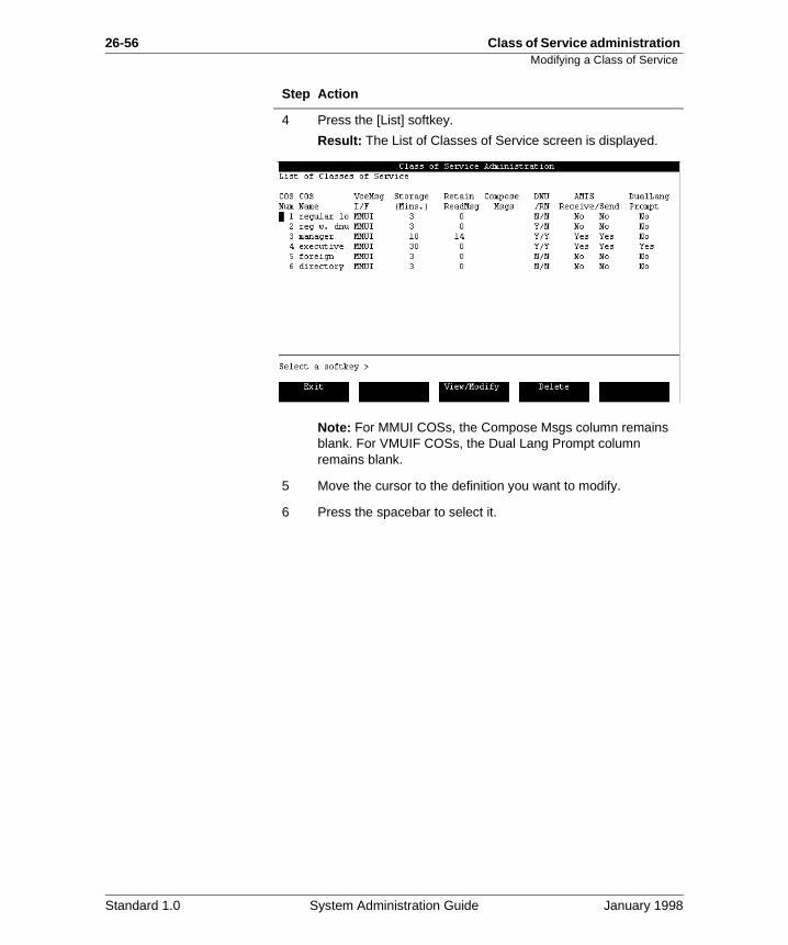
26-56 Class of Service administration Modifying a Class of Service
4 Press the [List] softkey.
Result: The List of Classes of Service screen is displayed.
Note: For MMUI COSs, the Compose Msgs column remains blank. For VMUIF COSs, the Dual Lang Prompt column remains blank.
5 Move the cursor to the definition you want to modify.
6 Press the spacebar to select it.
Step Action
Standard 1.0 System Administration Guide January 1998
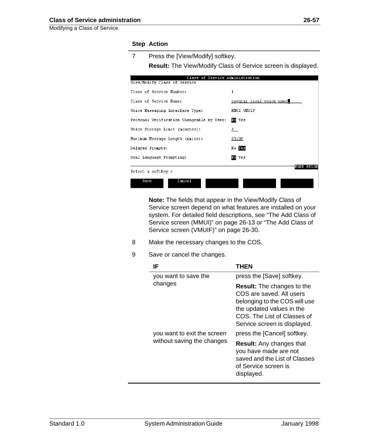
Class of Service administration 26-57Modifying a Class of Service
7 Press the [View/Modify] softkey.
Result: The View/Modify Class of Service screen is displayed.
Note: The fields that appear in the View/Modify Class of Service screen depend on what features are installed on your system. For detailed field descriptions, see “The Add Class of Service screen (MMUI)” on page 26-13 or “The Add Class of Service screen (VMUIF)” on page 26-30.
8 Make the necessary changes to the COS.
9 Save or cancel the changes.
Step Action
IF THEN
you want to save the changes
press the [Save] softkey.
Result: The changes to the COS are saved. All users belonging to the COS will use the updated values in the COS. The List of Classes of Service screen is displayed.
you want to exit the screen without saving the changes
press the [Cancel] softkey.
Result: Any changes that you have made are not saved and the List of Classes of Service screen is displayed.
Standard 1.0 System Administration Guide January 1998
26-58 Class of Service administration Modifying a Class of Service
e
I)”
Field descriptions The View/Modify Class of Service screen contains the samfields as the Add Class of Service screen. For field descriptions, see “The Add Class of Service screen (MMUon page 26-13 or “The Add Class of Service screen (VMUIF)” on page 26-30.
Standard 1.0 System Administration Guide January 1998
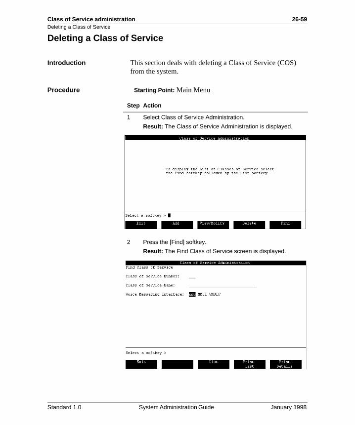
Class of Service administration 26-59Deleting a Class of Service
Deleting a Class of Service
Introduction This section deals with deleting a Class of Service (COS) from the system.
Procedure Starting Point: Main Menu
Step Action
1 Select Class of Service Administration.
Result: The Class of Service Administration is displayed.
2 Press the [Find] softkey.
Result: The Find Class of Service screen is displayed.
Standard 1.0 System Administration Guide January 1998
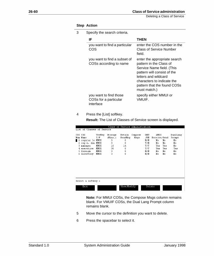
26-60 Class of Service administration Deleting a Class of Service
3 Specify the search criteria.
4 Press the [List] softkey.
Result: The List of Classes of Service screen is displayed.
Note: For MMUI COSs, the Compose Msgs column remains blank. For VMUIF COSs, the Dual Lang Prompt column remains blank.
5 Move the cursor to the definition you want to delete.
6 Press the spacebar to select it.
Step Action
IF THEN
you want to find a particular COS
enter the COS number in the Class of Service Number field.
you want to find a subset of COSs according to name
enter the appropriate search pattern in the Class of Service Name field. (This pattern will consist of the letters and wildcard characters to indicate the pattern that the found COSs must match.)
you want to find those COSs for a particular interface
specify either MMUI or VMUIF.
Standard 1.0 System Administration Guide January 1998
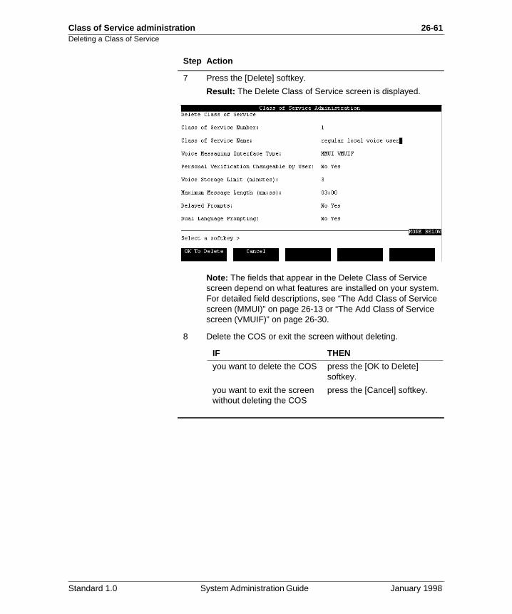
Class of Service administration 26-61Deleting a Class of Service
7 Press the [Delete] softkey.
Result: The Delete Class of Service screen is displayed.
Note: The fields that appear in the Delete Class of Service screen depend on what features are installed on your system. For detailed field descriptions, see “The Add Class of Service screen (MMUI)” on page 26-13 or “The Add Class of Service screen (VMUIF)” on page 26-30.
8 Delete the COS or exit the screen without deleting.
Step Action
IF THEN
you want to delete the COS press the [OK to Delete] softkey.
you want to exit the screen without deleting the COS
press the [Cancel] softkey.
Standard 1.0 System Administration Guide January 1998

26-62 Class of Service administration Deleting a Class of Service
Standard 1.0 System Administration Guide January 1998
Class of Service administration 26-63
Section C: Assigning Classes of Service to users
In this section
Assigning a Class of Service to a user 26-64
Creating and Assigning a Personal Class of Service to a user 26-65
The Class of Service conversion utility for converted systems 26-66
Standard 1.0 System Administration Guide January 1998
26-64 Class of Service administration Assigning a Class of Service to a user
ber
res.
Assigning a Class of Service to a user
Description To assign a user to a particular COS, select the COS numin the Class of Service field in the Add Local Voice User screen. For a complete description of this screen, see Chapter 8, “Local voice users”.
See also Please see Chapter 8, “Local voice users” for the procedu
Standard 1.0 System Administration Guide January 1998
Class of Service administration 26-65Creating and Assigning a Personal Class of Service to a user
of t
he is
ell
s of
Creating and Assigning a Personal Class of Service to a user
Description If a user has special requirements that are not met by anythe existing COSs, you can create a personal COS for thauser. All personal COSs must be maintained individually, since any changes made to a system COS will not affect tpersonal COSs that exist on the system. If, for example, itdecided that all users will be given access to a particular feature, you would have to modify all personal COSs as was the system COSs.
See also To create a personal COS, see “Assigning a user to a classervice” on page 8-20.
Standard 1.0 System Administration Guide January 1998
26-66 Class of Service administration The Class of Service conversion utility for converted systems
ier, e.
s,
an ser
d a
l
The Class of Service conversion utility for converted systems
Description If you have converted your system from Release 8 or earlall existing users will each have a personal class of servicThis means that all users still have their Meridian Mail Release 8 personal settings and are not connected to or related to any system COSs. Therefore, after a conversionyou must ensure that all existing users are reassigned to system COSs. This is done by adding the necessary COSthen using the COS Conversion utility.
Process This utility checks each user’s personal COS. If it matchesexisting system COS, the user is assigned to that COS. Umailboxes that do not match a system COS remain with personal COSs. You can use this utility to view these unassigned mailboxes and then use the utility to either adsystem COS based on the personal COSs or assign the unassigned mailbox to a defined COS.
See also The COS Conversion utility is available from the tools leveand allows you to reassign users to COSs. See the System Administration Tools Guide (NTP 555-7001-305) for details.
Standard 1.0 System Administration Guide January 1998
Chapter 27
Hardware administration
In this chapter
Overview 27-2
The Hardware Administration menu 27-3
Section A: Viewing the node configuration 27-5
Section B: Viewing the data port configuration 27-17
Section C: Printing node and data port information 27-45
27-2 Hardware administration Overview
ains in
n
Overview
Introduction The Hardware Administration screens allow you to view the contents of the hardware database in your Meridian Mail system.The hardware database is a system utility that mainta current listing and description of all nodes, cards, and portsyour system.
Available configurations
The MMP40 processor card is required for all Meridian Mail platforms, with the exception of Card Option. The Card Optioplatform uses the 68K processor card.
Modifying the hardware database
The Hardware Administration function allows you to view aspects of the Hardware database. If you or a representativefrom your support organization need to modify the hardwaredatabase, you must use the “Modify hardware” tool. Refer toSystem Administration Tools (NTP 555-7001-305).
CAUTIONRisk of audit failure
Do not leave any Hardware Administration menu on the administrative console overnight, as important system audits may fail due to lack of available memory, and there will be a security risk.
Standard 1.0 System Administration Guide January 1998
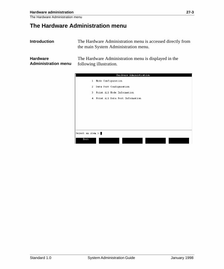
Hardware administration 27-3The Hardware Administration menu
The Hardware Administration menu
Introduction The Hardware Administration menu is accessed directly fromthe main System Administration menu.
Hardware Administration menu
The Hardware Administration menu is displayed in the following illustration.
Standard 1.0 System Administration Guide January 1998
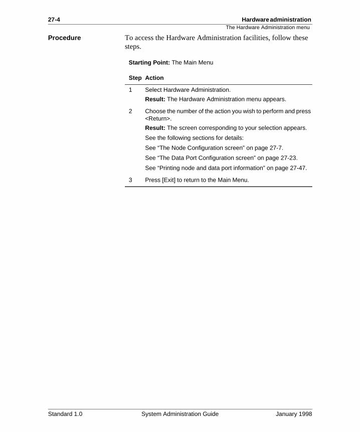
27-4 Hardware administration The Hardware Administration menu
e
Procedure To access the Hardware Administration facilities, follow thessteps.Starting Point: The Main Menu
Step Action
1 Select Hardware Administration.
Result: The Hardware Administration menu appears.
2 Choose the number of the action you wish to perform and press <Return>.
Result: The screen corresponding to your selection appears.
See the following sections for details:
See “The Node Configuration screen” on page 27-7.
See “The Data Port Configuration screen” on page 27-23.
See “Printing node and data port information” on page 27-47.
3 Press [Exit] to return to the Main Menu.
Standard 1.0 System Administration Guide January 1998
Hardware administration 27-5
Section A: Viewing the node configuration
In this section
Overview 27-6
The Node Configuration screen 27-7
The View Node screen 27-10
Standard 1.0 System Administration Guide January 1998
27-6 Hardware administration Overview
f
0).
Overview
Introduction The Node Configuration screen provides a summary listing othe cards found in all nodes in your system (see “The Node Configuration screen” on page 27-7).
The View Node screens provide a more detailed view of individual nodes (see “The View Node screen” on page 27-1
Standard 1.0 System Administration Guide January 1998
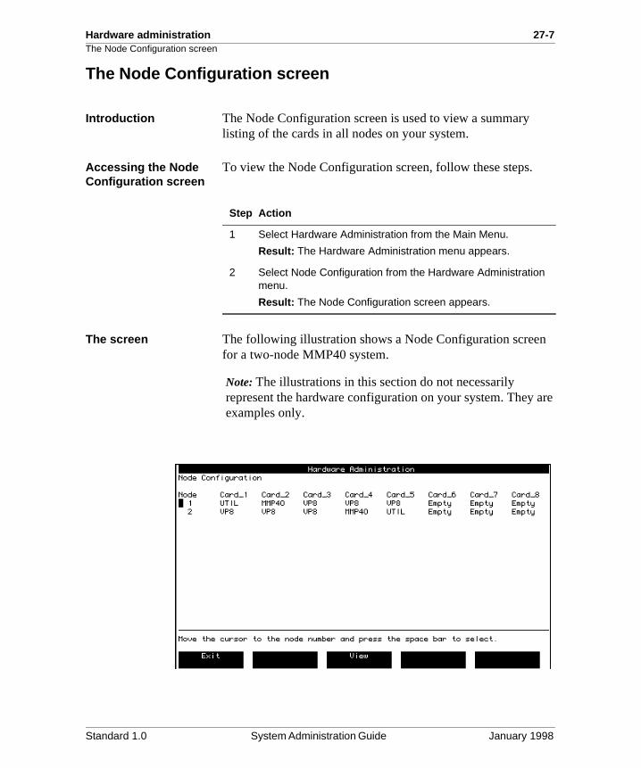
Hardware administration 27-7The Node Configuration screen
are
The Node Configuration screen
Introduction The Node Configuration screen is used to view a summary listing of the cards in all nodes on your system.
Accessing the Node Configuration screen
To view the Node Configuration screen, follow these steps.
The screen The following illustration shows a Node Configuration screenfor a two-node MMP40 system.
Note: The illustrations in this section do not necessarily represent the hardware configuration on your system. Theyexamples only.
Step Action
1 Select Hardware Administration from the Main Menu.
Result: The Hardware Administration menu appears.
2 Select Node Configuration from the Hardware Administration menu.
Result: The Node Configuration screen appears.
Standard 1.0 System Administration Guide January 1998
27-8 Hardware administration The Node Configuration screen
n.
g
, r
Field descriptions The following fields appear on the Node Configuration scree
Node
Description Refers to the number of the node within the configuration.
Default None.
Card_x
Description Identifies the card slot in the defined node, where“x” represents the position of the card slot. The card slots are numbered from left to right.
Valid entries The possible card types are listed here. Dependinon your system type, you will not see all of thesecards on your system.
MMP40 This is the Meridian Mail processor (CPU) card which includes a 24 MHz 68040 processor, 16 Mbytes of memory, up to two RS-232 serial portsand a SCSI interface processor. It is displayed foMMP40 systems.
RSMThis is an RS-232 service module (for non-EC systems).
BusThis is the high-speed bus (also called HABC forHigh Availability Bus Controller).
MSPThis is the multi-purpose signal processor.
NVP This is the 16 kbyte network voice processor.
NVP32This is the 32 kbyte network voice processor.
Standard 1.0 System Administration Guide January 1998
Hardware administration 27-9The Node Configuration screen
de
UTILThis card, on EC systems only, contains a high speed bus. It also includes four auxiliary RS-232ports. (1- to 4-node systems require one of thesecards; 5-node systems with 60 or more ports require two of these cards.)
VP4/VP8 cardsThese cards are voice processor cards that provifour and eight channels respectively.
EmptyThe card slot is empty.
Standard 1.0 System Administration Guide January 1998
27-10 Hardware administration The View Node screen
and s,
de
n
ds.
e
The View Node screen
Introduction The View Node screen provides a detailed view of the cards ports that make up a node, including card types and locationport types, and port attributes.
MSP nodes and SPN nodes
Two types of nodes are described in this section: an MSP noand an SPN node.
The MSP node is always node 1 on your system. It containssystem-related cards such as the MMP40 card. Depending othe system size, it may also contain voice cards.
An SPN node is a voice node and contains mostly voice carAll other nodes besides node 1 are SPN nodes.
Viewing node configurations
To view the node configurations for your system, follow thessteps.
Step Action
1 Select Hardware Administration from the Main Menu.
Result: The Hardware Administration menu appears.
2 Select Node Configuration from the Hardware Administration menu.
Result: The Node Configuration screen appears.
3 Move the cursor to the node you want to view and press <Spacebar>.
Result: Your selection is highlighted.
4 Select [View] to view the configuration information for the highlighted node.
Result: The View Node screen appears. See “View Node screen (MSP node)” on page 27-11. and “View Node screen (SPN node)” on page 27-12 for examples.
5 Select [Exit] to return to the Node Configuration screen when you have finished viewing the node configuration. Select [Exit] again to return to the Hardware Administration main menu.
Standard 1.0 System Administration Guide January 1998
Hardware administration 27-11The View Node screen
e
View Node screen (MSP node)
The following diagram illustrates a View Node screen for an EC MMP40 system when the node is an MSP node.
Note: If the MMP40 node you are viewing is an MSP node, thfollowing types of cards may be installed:
• MMP40, Bus, RSM, and VP on non-EC systems
• MMP40, UTIL, and VP on EC systems
Standard 1.0 System Administration Guide January 1998
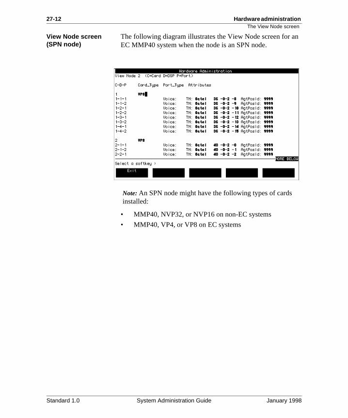
27-12 Hardware administration The View Node screen
n
View Node screen (SPN node)The following diagram illustrates the View Node screen for aEC MMP40 system when the node is an SPN node.
Note: An SPN node might have the following types of cards installed:
• MMP40, NVP32, or NVP16 on non-EC systems
• MMP40, VP4, or VP8 on EC systems
Standard 1.0 System Administration Guide January 1998
Hardware administration 27-13The View Node screen
ing
, r
Field descriptions The View Node screens display the following read-only information about each card on the node.
C-D-P
Description This is the physical location of the port in the Meridian Mail system, where
• C is the card
• D is the DSP number (which is displayed for voice processor cards only)
• P is the port number
Card_Type
Description This indicates the function of the card.
Valid entries The possible card types are listed here. Dependon your system type, you will not see all of thesecards on your system.
MMP40 This is the Meridian Mail processor (CPU) card which includes a 24 MHz 68040 processor, 16 Mbytes of memory, up to two RS-232 serial portsand a SCSI interface processor. It is displayed foMMP40 systems.
RSMThis is an RS-232 service module (for non-EC systems).
BusThis is the high-speed bus (also called HABC forHigh Availability Bus Controller).
MSPThis is the multi-purpose signal processor.
NVP This is the 16 kbyte network voice processor.
NVP32This is the 32 kbyte network voice processor.
Standard 1.0 System Administration Guide January 1998
27-14 Hardware administration The View Node screen
ide
rt
UTILThis card, on EC systems only, contains a high speed bus. It also includes four auxiliary RS-232ports. (1- to 4-node systems require one of thesecards; 5-node systems with 60 or more ports require two of these cards.)
VP4/VP8 cardsThese cards are voice processor cards that provfour and eight channels respectively.
EmptyThe card slot is empty.
Port_Type
Description This field describes the type of port, where
• Data indicates a serial data communications po
• Device indicates a mass storage device or tapedrive
• Voice indicates a voice processor port
• Multi indicates a multimedia port
J4 (UTIL card only)
Description This indicates the Meridian 1 network loop number connected to J4 on the utility card. This field is read-only, and is configured at the Tools level. See the System Administration Tools Guide (NTP 555-7001-305).
J5 (UTIL card only)
Description This indicates the Meridian 1 network loop number connected to J5 on the utility card. This field is read-only, and is configured at the Tools level. See the System Administration Tools Guide (NTP 555-7001-305).
Standard 1.0 System Administration Guide January 1998
Hardware administration 27-15The View Node screen
il
il
d
Attributes (for ports with type = Data)
Description • Terminal indicates a connection to an administration terminal.
• Printer indicates a printer serial connection.
• NWModem indicates a connection to a modemused for networking calls.
Note: Ports on the MMP40 and the SBC card do not support networking. The RSM card (on non-EC systems) or UTIL card (on EC systems) do support networking.
• MMLink indicates the Meridian ACCESS Link,which is the communications channel for Meridian ACCESS.
• AML/CSL (Meridian Link) indicates there is a communications channel between Meridian Maand a Meridian 1.
• SMDI (not applicable) indicates a communications channel between Meridian Maand a DMS-100, DMS-10, SL-100, AT&T, ROLM, or NEC switch.
• PMS (for Hospitality systems) is the serial link between Meridian Mail, the PMS system, and the Meridian 1 for PMS data.
• AdminPlus indicates a connection to a PC equipped with Meridian Mail Reporter.
• Modem indicates a connection to a modem usefor remote access.
• MSLink indicates a connection to a PC runningMeridian Mail AutoAdmin.
Attributes (for ports with type = Device)
Description • Disk indicates a mass storage subsystem (harddisk) is present.
• Tape indicates a cartridge tape subsystem is present.
Standard 1.0 System Administration Guide January 1998
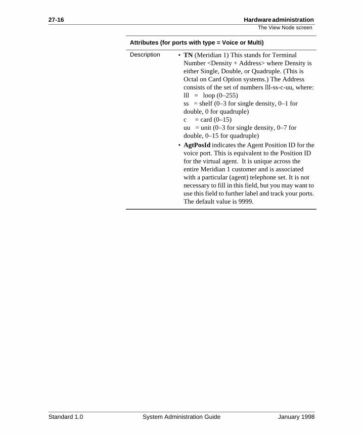
27-16 Hardware administration The View Node screen
e:
s.
Attributes (for ports with type = Voice or Multi)
Description • TN (Meridian 1) This stands for Terminal Number <Density + Address> where Density iseither Single, Double, or Quadruple. (This is Octal on Card Option systems.) The Address consists of the set of numbers lll-ss-c-uu, wherlll = loop (0–255)ss = shelf (0–3 for single density, 0–1 for double, 0 for quadruple)c = card (0–15)uu = unit (0–3 for single density, 0–7 for double, 0–15 for quadruple)
• AgtPosId indicates the Agent Position ID for thevoice port. This is equivalent to the Position IDfor the virtual agent. It is unique across the entire Meridian 1 customer and is associated with a particular (agent) telephone set. It is notnecessary to fill in this field, but you may want touse this field to further label and track your portThe default value is 9999.
Standard 1.0 System Administration Guide January 1998
Hardware administration 27-17
Section B: Viewing the data port configuration
In this section
Overview 27-18
The Data Port Configuration screen 27-23
Viewing data ports 27-25
View Terminal data ports 27-27
View Printer data port 27-30
View MMLink data port 27-32
View/Modify NWModem data port 27-34
View PMS data port 27-36
View AdminPlus data port 27-38
View Modem data port 27-40
View MSLink data port 27-42
Standard 1.0 System Administration Guide January 1998
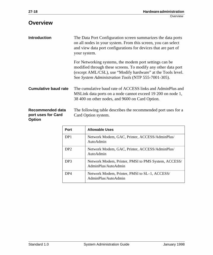
27-18 Hardware administration Overview
rts t
ort .
nd 1,
r a
/
Overview
Introduction The Data Port Configuration screen summarizes the data poon all nodes in your system. From this screen, you can selecand view data port configurations for devices that are part ofyour system.
For Networking systems, the modem port settings can be modified through these screens. To modify any other data p(except AML/CSL), use “Modify hardware” at the Tools levelSee System Administration Tools (NTP 555-7001-305).
Cumulative baud rate The cumulative baud rate of ACCESS links and AdminPlus aMSLink data ports on a node cannot exceed 19 200 on node38 400 on other nodes, and 9600 on Card Option.
Recommended data port uses for Card Option
The following table describes the recommended port uses foCard Option system.
Port Allowable Uses
DP1 Network Modem, GAC, Printer, ACCESS/AdminPlus/AutoAdmin
DP2 Network Modem, GAC, Printer, ACCESS/AdminPlus/AutoAdmin
DP3 Network Modem, Printer, PMSI to PMS System, ACCESSAdminPlus/AutoAdmin
DP4 Network Modem, Printer, PMSI to SL–1, ACCESS/ AdminPlus/AutoAdmin
Standard 1.0 System Administration Guide January 1998
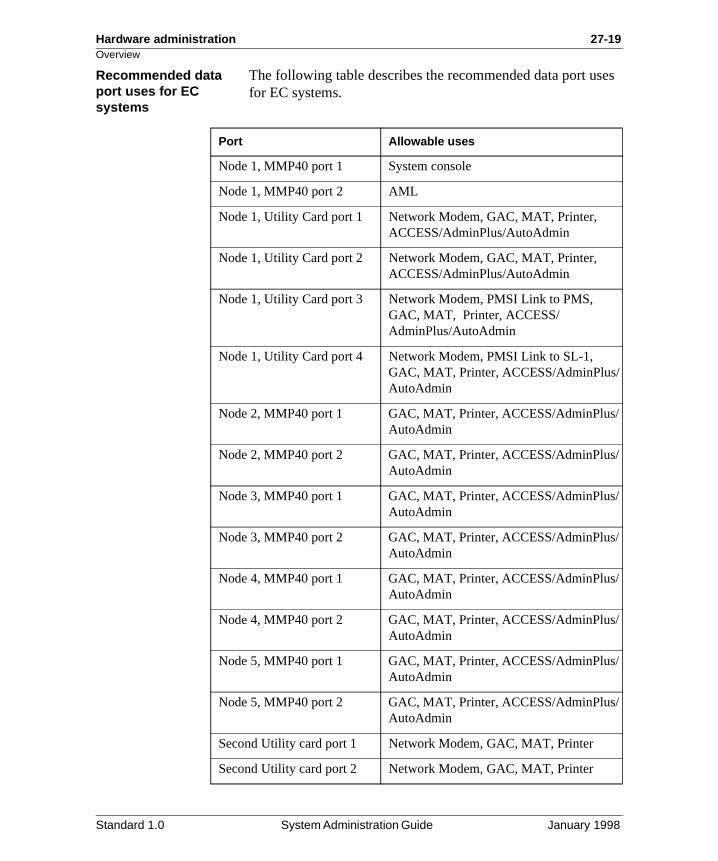
Hardware administration 27-19Overview
es
/
/
/
/
/
/
/
/
Recommended data port uses for EC systems
The following table describes the recommended data port usfor EC systems.
Port Allowable uses
Node 1, MMP40 port 1 System console
Node 1, MMP40 port 2 AML
Node 1, Utility Card port 1 Network Modem, GAC, MAT, Printer, ACCESS/AdminPlus/AutoAdmin
Node 1, Utility Card port 2 Network Modem, GAC, MAT, Printer, ACCESS/AdminPlus/AutoAdmin
Node 1, Utility Card port 3 Network Modem, PMSI Link to PMS, GAC, MAT, Printer, ACCESS/AdminPlus/AutoAdmin
Node 1, Utility Card port 4 Network Modem, PMSI Link to SL-1, GAC, MAT, Printer, ACCESS/AdminPlus/AutoAdmin
Node 2, MMP40 port 1 GAC, MAT, Printer, ACCESS/AdminPlusAutoAdmin
Node 2, MMP40 port 2 GAC, MAT, Printer, ACCESS/AdminPlusAutoAdmin
Node 3, MMP40 port 1 GAC, MAT, Printer, ACCESS/AdminPlusAutoAdmin
Node 3, MMP40 port 2 GAC, MAT, Printer, ACCESS/AdminPlusAutoAdmin
Node 4, MMP40 port 1 GAC, MAT, Printer, ACCESS/AdminPlusAutoAdmin
Node 4, MMP40 port 2 GAC, MAT, Printer, ACCESS/AdminPlusAutoAdmin
Node 5, MMP40 port 1 GAC, MAT, Printer, ACCESS/AdminPlusAutoAdmin
Node 5, MMP40 port 2 GAC, MAT, Printer, ACCESS/AdminPlusAutoAdmin
Second Utility card port 1 Network Modem, GAC, MAT, Printer
Second Utility card port 2 Network Modem, GAC, MAT, Printer
Standard 1.0 System Administration Guide January 1998
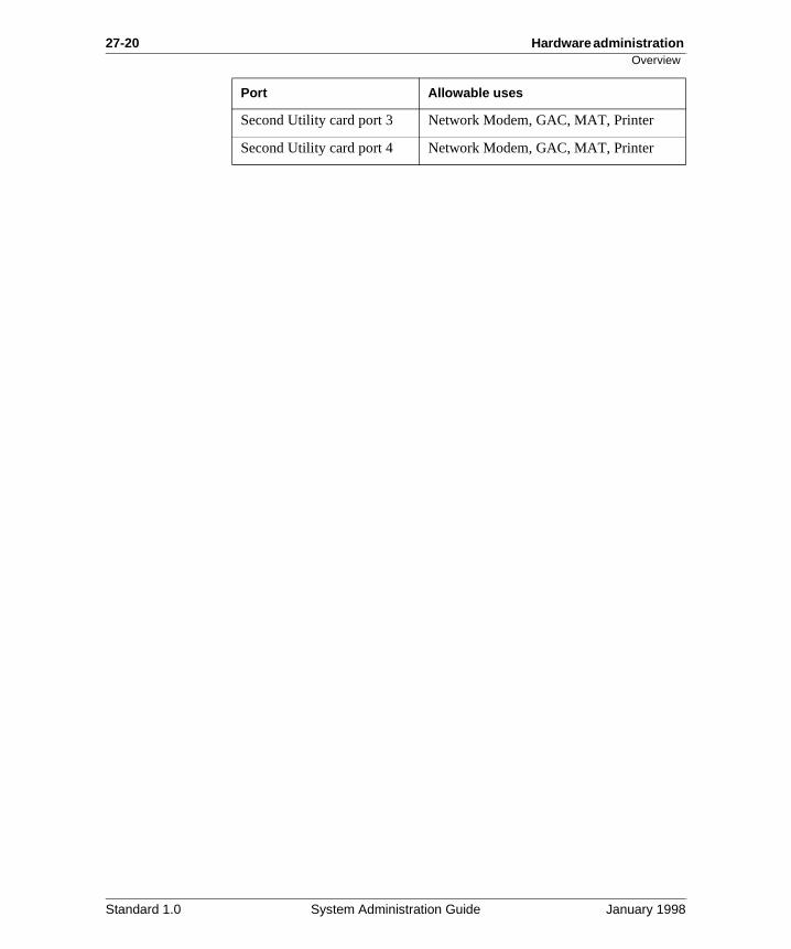
27-20 Hardware administration Overview
Second Utility card port 3 Network Modem, GAC, MAT, Printer
Second Utility card port 4 Network Modem, GAC, MAT, Printer
Port Allowable uses
Standard 1.0 System Administration Guide January 1998
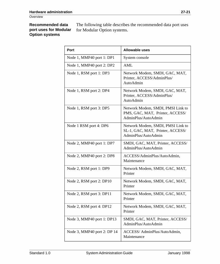
Hardware administration 27-21Overview
es
Recommended data port uses for Modular Option systems
The following table describes the recommended data port usfor Modular Option systems.
Port Allowable uses
Node 1, MMP40 port 1: DP1 System console
Node 1, MMP40 port 2: DP2 AML
Node 1, RSM port 1: DP3 Network Modem, SMDI, GAC, MAT, Printer, ACCESS/AdminPlus/AutoAdmin
Node 1, RSM port 2: DP4 Network Modem, SMDI, GAC, MAT, Printer, ACCESS/AdminPlus/AutoAdmin
Node 1, RSM port 3: DP5 Network Modem, SMDI, PMSI Link to PMS, GAC, MAT, Printer, ACCESS/ AdminPlus/AutoAdmin
Node 1 RSM port 4: DP6 Network Modem, SMDI, PMSI Link toSL-1, GAC, MAT, Printer, ACCESS/AdminPlus/AutoAdmin
Node 2, MMP40 port 1: DP7 SMDI, GAC, MAT, Printer, ACCESS/ AdminPlus/AutoAdmin
Node 2, MMP40 port 2: DP8 ACCESS/AdminPlus/AutoAdmin, Maintenance
Node 2, RSM port 1: DP9 Network Modem, SMDI, GAC, MAT, Printer
Node 2, RSM port 2: DP10 Network Modem, SMDI, GAC, MAT, Printer
Node 2, RSM port 3: DP11 Network Modem, SMDI, GAC, MAT, Printer
Node 2, RSM port 4: DP12 Network Modem, SMDI, GAC, MAT, Printer
Node 3, MMP40 port 1: DP13 SMDI, GAC, MAT, Printer, ACCESS/AdminPlus/AutoAdmin
Node 3, MMP40 port 2: DP 14 ACCESS/ AdminPlus/AutoAdmin, Maintenance
Standard 1.0 System Administration Guide January 1998
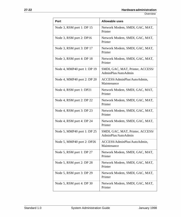
27-22 Hardware administration Overview
Node 3, RSM port 1: DP 15 Network Modem, SMDI, GAC, MAT, Printer
Node 3, RSM port 2: DP16 Network Modem, SMDI, GAC, MAT, Printer
Node 3, RSM port 3: DP 17 Network Modem, SMDI, GAC, MAT, Printer
Node 3, RSM port 4: DP 18 Network Modem, SMDI, GAC, MAT, Printer
Node 4, MMP40 port 1: DP 19 SMDI, GAC, MAT, Printer, ACCESS/AdminPlus/AutoAdmin
Node 4, MMP40 port 2: DP 20 ACCESS/AdminPlus/AutoAdmin, Maintenance
Node 4, RSM port 1: DP21 Network Modem, SMDI, GAC, MAT, Printer
Node 4, RSM port 2: DP 22 Network Modem, SMDI, GAC, MAT, Printer
Node 4, RSM port 3: DP 23 Network Modem, SMDI, GAC, MAT, Printer
Node 4, RSM port 4: DP 24 Network Modem, SMDI, GAC, MAT, Printer
Node 5, MMP40 port 1: DP 25 SMDI, GAC, MAT, Printer, ACCESS/AdminPlus/AutoAdmin
Node 5, MMP40 port 2: DP26 ACCESS/AdminPlus/AutoAdmin, Maintenance
Node 5, RSM port 1: DP 27 Network Modem, SMDI, GAC, MAT, Printer
Node 5, RSM port 2: DP 28 Network Modem, SMDI, GAC, MAT, Printer
Node 5, RSM port 3: DP 29 Network Modem, SMDI, GAC, MAT, Printer
Node 5, RSM port 4: DP 30 Network Modem, SMDI, GAC, MAT, Printer
Port Allowable uses
Standard 1.0 System Administration Guide January 1998
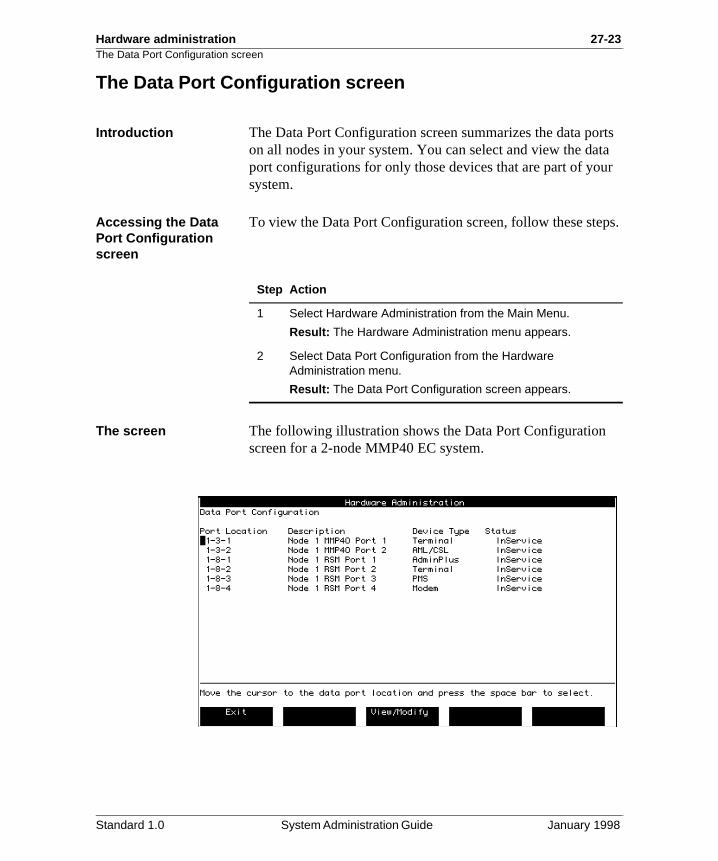
Hardware administration 27-23The Data Port Configuration screen
rts ta r
ps.
The Data Port Configuration screen
Introduction The Data Port Configuration screen summarizes the data poon all nodes in your system. You can select and view the daport configurations for only those devices that are part of yousystem.
Accessing the Data Port Configuration screen
To view the Data Port Configuration screen, follow these ste
The screen The following illustration shows the Data Port Configuration screen for a 2-node MMP40 EC system.
Step Action
1 Select Hardware Administration from the Main Menu.
Result: The Hardware Administration menu appears.
2 Select Data Port Configuration from the Hardware Administration menu.
Result: The Data Port Configuration screen appears.
Standard 1.0 System Administration Guide January 1998
27-24 Hardware administration The Data Port Configuration screen
.
f
he
rt.
re
Field descriptions The Data Port Configuration screen displays the following information.
Port Location
Description This is the physical location of the port in the Meridian Mail system (node-card-port).
Description
Description This field identifies the node, card type, and port
Device Type
Description This field identifies the function of the port.
Valid values See the data port tables in the “Overview” on page 27-18.
Status
Description This field identifies the current operational state othe port.
Valid values The status will be one of the following:
InServiceThe data port is operational.
OutOfServiceThe data port is no longer operational because tnode has been disabled.
FaultyThe system has detected an error in the data po
UnequippedThe data port has not been defined in the hardwadatabase.
Standard 1.0 System Administration Guide January 1998
Hardware administration 27-25Viewing data ports
n be cted
Viewing data ports
Introduction This section describes the different data port screens that cadisplayed. Depending on the device type that has been selewhen you press View/Modify, the appropriate version of the View Data Port screen appears as follows:
• Terminal data ports (console or MAT/GAC)
• Printer data ports
• MMLink data ports
• NWModem data ports
• PMS data ports
• AdminPlus data ports
• Modem data ports
• MSLink data ports
Procedure To view data ports, follow these steps.
Step Action
1 Select “Hardware Administration” from the Main Menu.
Result: The Hardware Administration menu appears.
2 Select Data Port Configuration from the Hardware Administration menu.
Result: The Data Port Configuration screen appears.
Standard 1.0 System Administration Guide January 1998
27-26 Hardware administration Viewing data ports
3 Move the cursor to the port you want to view (or modify, if NWModem) and press <Space Bar>.
Result: Your selection is highlighted.
4 Select [View/Modify] to view the configuration information for the highlighted port.
Result: The View Node screen appears for the selected device. (If NWModem was selected, the Modify Data Port screen is displayed.) For further information, see the appropriate section for the selected device, as follows:
“View Terminal data ports” on page 27-27
“View Data Port screen—MAT or GAC” on page 27-28
“View Printer data port” on page 27-30
“View MMLink data port” on page 27-32
“View/Modify NWModem data port” on page 27-34
“View PMS data port” on page 27-36
“View Modem data port” on page 27-40
“View MSLink data port” on page 27-42
5 Select [Exit] to return to the Data Port Configuration screen when you have finished viewing the data port configuration. Select [Exit] again to return to the Hardware Administration screen.
Result: The “Hardware Administration” screen is redisplayed.
Step Action
Standard 1.0 System Administration Guide January 1998
Hardware administration 27-27View Terminal data ports
u ted
View Terminal data ports
View Data Port screen—Console
The View Data Port screen for terminals (Console) allows yoto view information about the terminal connected to the selecport.
Standard 1.0 System Administration Guide January 1998
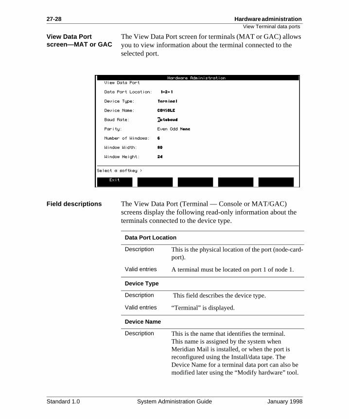
27-28 Hardware administration View Terminal data ports
s
d-
View Data Port screen—MAT or GAC
The View Data Port screen for terminals (MAT or GAC) allowyou to view information about the terminal connected to the selected port.
Field descriptions The View Data Port (Terminal — Console or MAT/GAC) screens display the following read-only information about theterminals connected to the device type.
Data Port Location
Description This is the physical location of the port (node-carport).
Valid entries A terminal must be located on port 1 of node 1.
Device Type
Description This field describes the device type.
Valid entries “Terminal” is displayed.
Device Name
Description This is the name that identifies the terminal.This name is assigned by the system when Meridian Mail is installed, or when the port is reconfigured using the Install/data tape. The Device Name for a terminal data port can also bemodified later using the “Modify hardware” tool.
Standard 1.0 System Administration Guide January 1998
Hardware administration 27-29View Terminal data ports
ch
d.
g
Baud Rate
Description The selected baud rate is highlighted.
Valid entries The baud rate must be set to 2400 for all systemtypes except Card Option. For Card Option systems, 2400 is recommended, but it must matthe baud rate set on the Option 11 switch.
Parity
Description This is the method by which data is communicate
Valid entries This can be set to Even, Odd, or None, dependinon the current setup of the terminal connected tothe port. It is usually set to None.
Number of Windows
Description This field specifies the number of windows that can be used simultaneously.
Valid entries Set this field to 6 for the system administration terminal.
Window Width
Description This field specifies the window width used.
Valid entries Set this field to 80 for the terminal.
Window Height
Description This field specifies the window height used.
Valid entries Set this field to 24 for the terminal.
Standard 1.0 System Administration Guide January 1998
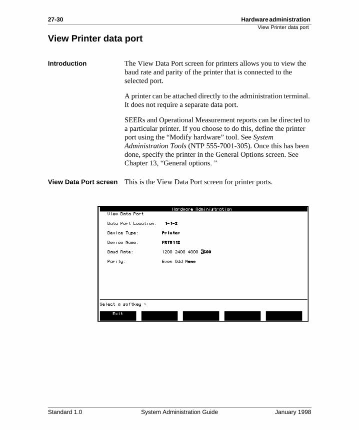
27-30 Hardware administration View Printer data port
e
al.
d to r
n
View Printer data port
Introduction The View Data Port screen for printers allows you to view thbaud rate and parity of the printer that is connected to the selected port.
A printer can be attached directly to the administration terminIt does not require a separate data port.
SEERs and Operational Measurement reports can be directea particular printer. If you choose to do this, define the printeport using the “Modify hardware” tool. See System Administration Tools (NTP 555-7001-305). Once this has beedone, specify the printer in the General Options screen. SeeChapter 13, “General options. ”
View Data Port screen This is the View Data Port screen for printer ports.
Standard 1.0 System Administration Guide January 1998
Hardware administration 27-31View Printer data port
d-
y
e
d.
e
Field descriptions The View Data Port (Printer) screen displays the following read-only information about the terminals connected to the device type.
Data Port Location
Description This is the physical location of the port (node-carport).
Device Type
Description This field describes the device type.
Valid entries “Printer” is displayed.
Device Name
Description This is the name that identifies the printer data port. This name is assigned by the system whenMeridian Mail is installed, or when the port is reconfigured using Install/data tape or the “Modifhardware” tool.
Baud Rate
Description The selected baud rate is highlighted.
Valid entries The setting will depend on the current setup of thprinter connected to the port.
Parity
Description This is the method by which data is communicate
Valid entries The setting will depend on the current setup of thprinter connected to the port.
Standard 1.0 System Administration Guide January 1998
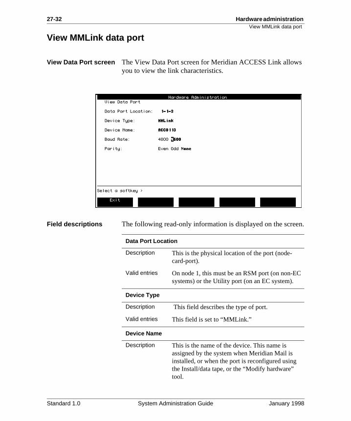
27-32 Hardware administration View MMLink data port
s
n.
View MMLink data port
View Data Port screen The View Data Port screen for Meridian ACCESS Link allowyou to view the link characteristics.
Field descriptions The following read-only information is displayed on the scree
Data Port Location
Description This is the physical location of the port (node-card-port).
Valid entries On node 1, this must be an RSM port (on non-ECsystems) or the Utility port (on an EC system).
Device Type
Description This field describes the type of port.
Valid entries This field is set to “MMLink.”
Device Name
Description This is the name of the device. This name is assigned by the system when Meridian Mail is installed, or when the port is reconfigured using the Install/data tape, or the “Modify hardware” tool.
Standard 1.0 System Administration Guide January 1998
Hardware administration 27-33View MMLink data port
r
.
Baud Rate
Description This field can be set to any rate for MMLink, subject to the cumulative baud rates specified fothe system.
Valid entries 4800 and 9600 are the only available baud rates
Parity
Description This is the method by which data is communicated.
Valid entries This field is not used for MMLink.
Standard 1.0 System Administration Guide January 1998
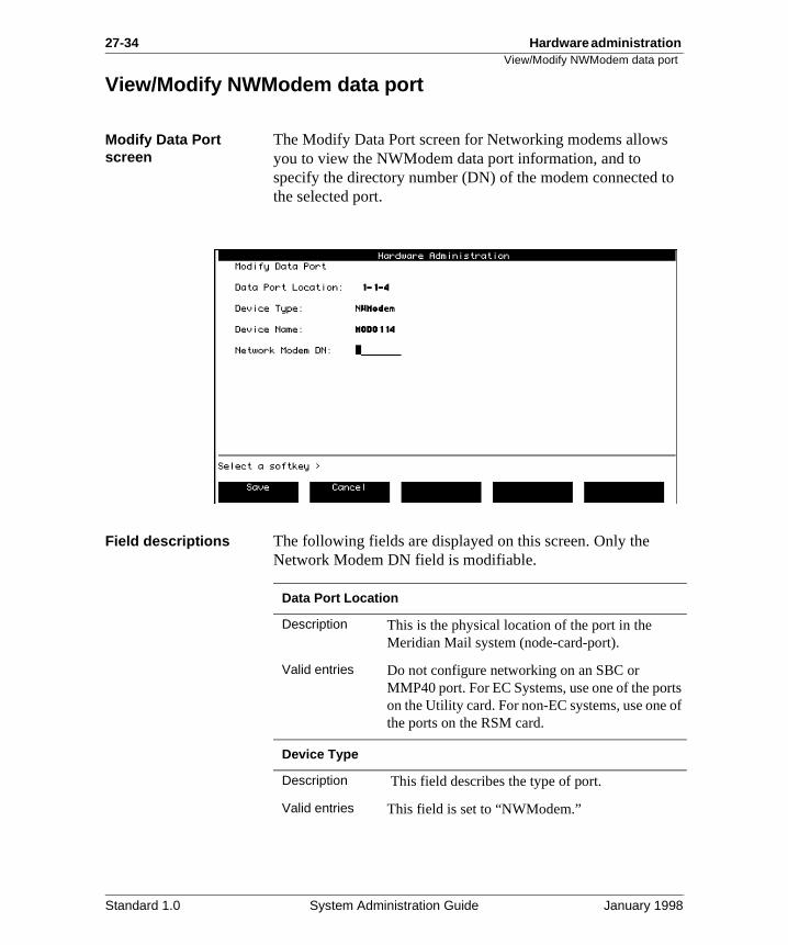
27-34 Hardware administration View/Modify NWModem data port
to
rts of
View/Modify NWModem data port
Modify Data Port screen
The Modify Data Port screen for Networking modems allowsyou to view the NWModem data port information, and to specify the directory number (DN) of the modem connected the selected port.
Field descriptions The following fields are displayed on this screen. Only the Network Modem DN field is modifiable.
Data Port Location
Description This is the physical location of the port in the Meridian Mail system (node-card-port).
Valid entries Do not configure networking on an SBC or MMP40 port. For EC Systems, use one of the poon the Utility card. For non-EC systems, use one the ports on the RSM card.
Device Type
Description This field describes the type of port.
Valid entries This field is set to “NWModem.”
Standard 1.0 System Administration Guide January 1998
Hardware administration 27-35View/Modify NWModem data port
t.
Device Name
Description This is the name of the device. This name is assigned by the system when Meridian Mail is installed, or when the port is reconfigured using the Install/data tape, or the “Modify hardware” tool.
Network Modem DN
Description This is the directory number (up to eight digits) used to identify the modem connected to the por
Standard 1.0 System Administration Guide January 1998
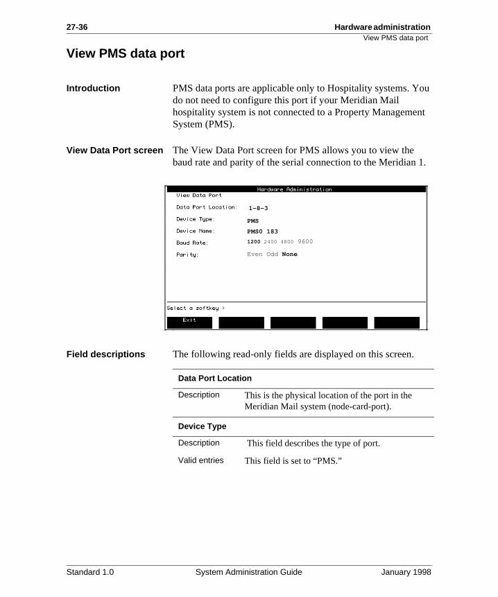
27-36 Hardware administration View PMS data port
ou
nt
1.
View PMS data port
Introduction PMS data ports are applicable only to Hospitality systems. Ydo not need to configure this port if your Meridian Mail hospitality system is not connected to a Property ManagemeSystem (PMS).
View Data Port screen The View Data Port screen for PMS allows you to view the baud rate and parity of the serial connection to the Meridian
Field descriptions The following read-only fields are displayed on this screen.
PMS
PMS0 183
Even Odd None
1200 2400 4800 9600
1-8-3
Data Port Location
Description This is the physical location of the port in the Meridian Mail system (node-card-port).
Device Type
Description This field describes the type of port.
Valid entries This field is set to “PMS.”
Standard 1.0 System Administration Guide January 1998
Hardware administration 27-37View PMS data port
d.
Device Name
Description This is the name of the device. This name is assigned by the system when Meridian Mail is installed, or when the port is reconfigured using the Install/data tape, or the “Modify hardware” tool.
Baud Rate
Description The selected baud rate is highlighted.
Valid entries The baud rate must be set to 1200.
Parity
Description This is the method by which data is communicate
Valid entries This field must be set to None.
Standard 1.0 System Administration Guide January 1998
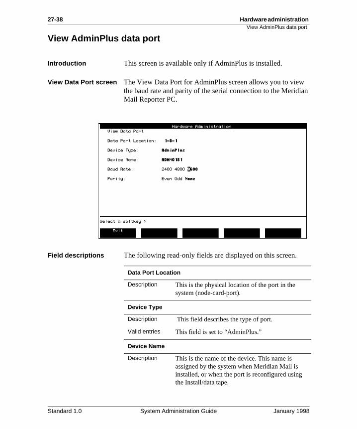
27-38 Hardware administration View AdminPlus data port
ian
View AdminPlus data port
Introduction This screen is available only if AdminPlus is installed.
View Data Port screen The View Data Port for AdminPlus screen allows you to viewthe baud rate and parity of the serial connection to the MeridMail Reporter PC.
Field descriptions The following read-only fields are displayed on this screen.
Data Port Location
Description This is the physical location of the port in the system (node-card-port).
Device Type
Description This field describes the type of port.
Valid entries This field is set to “AdminPlus.”
Device Name
Description This is the name of the device. This name is assigned by the system when Meridian Mail is installed, or when the port is reconfigured using the Install/data tape.
Standard 1.0 System Administration Guide January 1998
Hardware administration 27-39View AdminPlus data port
00, r .
d.
Baud Rate
Description The selected baud rate is highlighted.
Valid entries The baud rate should be set to 2400, 4800, or 96subject to the cumulative baud rate restrictions foMMLink, MSLink, and AdminPlus data ports on anode. See “Cumulative baud rate” on page 27-18
Parity
Description This is the method by which data is communicate
Valid entries This field must be set to None.
Standard 1.0 System Administration Guide January 1998
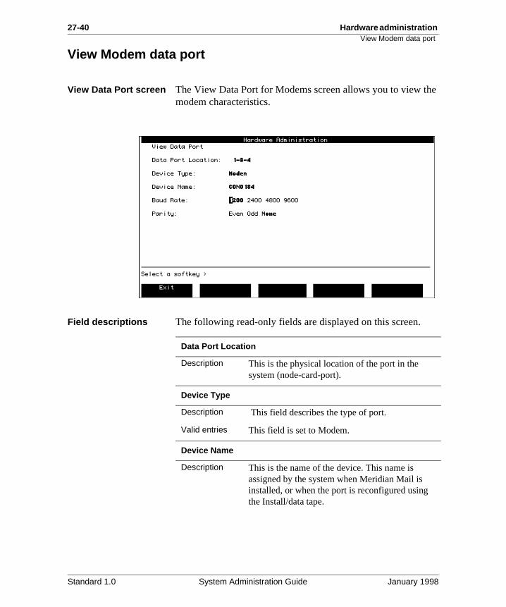
27-40 Hardware administration View Modem data port
he
View Modem data port
View Data Port screen The View Data Port for Modems screen allows you to view tmodem characteristics.
Field descriptions The following read-only fields are displayed on this screen.
Data Port Location
Description This is the physical location of the port in the system (node-card-port).
Device Type
Description This field describes the type of port.
Valid entries This field is set to Modem.
Device Name
Description This is the name of the device. This name is assigned by the system when Meridian Mail is installed, or when the port is reconfigured using the Install/data tape.
Standard 1.0 System Administration Guide January 1998
Hardware administration 27-41View Modem data port
d.
Baud Rate
Description The selected baud rate is highlighted.
Valid entries The setting depends on the current setup of the modem connected to the port.
Parity
Description This is the method by which data is communicate
Valid entries The setting depends on the current setup of the modem connected to the port.
Standard 1.0 System Administration Guide January 1998
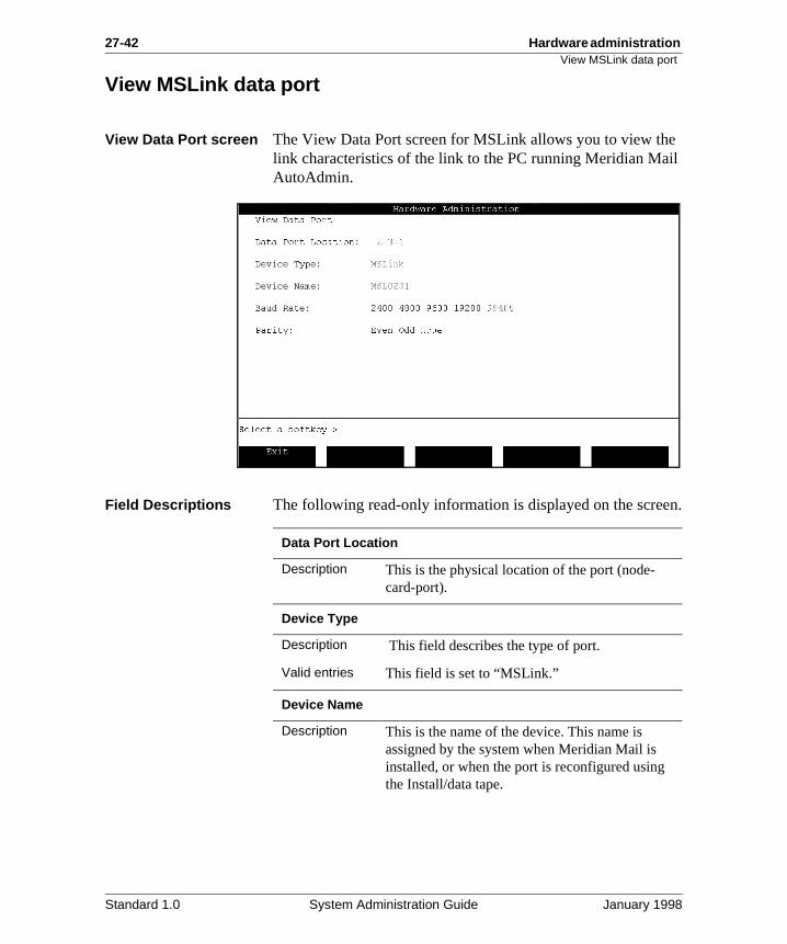
27-42 Hardware administration View MSLink data port
e il
n.
View MSLink data port
View Data Port screen The View Data Port screen for MSLink allows you to view thlink characteristics of the link to the PC running Meridian MaAutoAdmin.
Field Descriptions The following read-only information is displayed on the scree
Data Port Location
Description This is the physical location of the port (node-card-port).
Device Type
Description This field describes the type of port.
Valid entries This field is set to “MSLink.”
Device Name
Description This is the name of the device. This name is assigned by the system when Meridian Mail is installed, or when the port is reconfigured using the Install/data tape.
Standard 1.0 System Administration Guide January 1998
Hardware administration 27-43View MSLink data port
r
Baud Rate
Description This field can be set to any rate for MSLink, subject to the cumulative baud rates specified fothe system.
Valid entries 2400, 4800, 9600, 19 200, and 38 400 are the available baud rates.
Parity
Description This is the method by which data is communicated.
Valid entries This field must be set to None. It cannot be modified.
Standard 1.0 System Administration Guide January 1998

27-44 Hardware administration View MSLink data port
Standard 1.0 System Administration Guide January 1998
Hardware administration 27-45
Section C: Printing node and data port information
In this section
Overview 27-46
Printing node and data port information 27-47
Standard 1.0 System Administration Guide January 1998
27-46 Hardware administration Overview
Overview
Introduction The Hardware Administration menu can be used to print thefollowing information for your system:
• node configuration
• data port configuration
Standard 1.0 System Administration Guide January 1998
Hardware administration 27-47Printing node and data port information
Printing node and data port information
Introduction Node and data port information can be printed through the Hardware Administration menu.
Procedure To print node and data port information, follow these steps.
Step Action
1 Select “Hardware Administration” from the Main Menu.
Result: The Hardware Administration menu appears.
2 Choose either “Print All Node Information” or “Print All Data Port Information” and press <Return>.
Result: The following softkeys appear: [Continue Printing] and [Cancel Printing].You are prompted to check that the printer is ready and online.
3 Press [Continue Printing] to print the information.
Result: The node or data port information begins printing. Once printing is complete, the Hardware Administration menu is redisplayed. You may stop printing at any time by selecting [Cancel Printing].
4 Use [Cancel Printing] to cancel printing and return to the Hardware Administration menu.
Result: Printing stops and the Hardware Administration menu is displayed. There may be some delay before control is returned to the screen while the system waits for the printer to stop printing.
Standard 1.0 System Administration Guide January 1998

27-48 Hardware administration Printing node and data port information
Standard 1.0 System Administration Guide January 1998
Chapter 28
System status and maintenance
In this chapter
Overview 28-2
What is system status and maintenance? 28-3
Section A: System Status 28-5
Section B: Card Status 28-19
Section C: DSP Port Status 28-29
Section D: Channel Allocation Table 28-45
Section E: Disk Maintenance 28-61
Section F: Diagnostic Schedules 28-75
28-2 System status and maintenance Overview
n
he
lso nd
ng
ey lls
Overview
Introduction The System Status and Maintenance function provides monitoring and control screens through which you can obtaiviews of the operational state of the system at four levels:
• system
• card
• DSP port
• disk
The System Status and Maintenance functions are used in tcourse of routine maintenance, and allow you to take any component of the system out of service for maintenance. It aallows you to perform diagnostics on selected components aschedule regular diagnostic activities.
A component can be taken out of service by disabling it (forciit out of its operational state), or by performing a courtesy disable, which progressively disables active DSP ports as thbecome idle. The Courtesy Disable function available withinSystem Status and Maintenance avoids any disruption of cain progress.
See also For help in developing a regular maintenance routine that includes System Status and Maintenance functions, see Chapter 18, “Routine maintenance”.
Standard 1.0 System Administration Guide January 1998
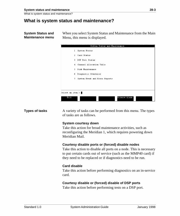
System status and maintenance 28-3What is system status and maintenance?
ain
es
ary ) if
ice
What is system status and maintenance?
System Status and Maintenance menu
When you select System Status and Maintenance from the MMenu, this menu is displayed.
Types of tasks A variety of tasks can be performed from this menu. The typof tasks are as follows.
System courtesy downTake this action for broad maintenance activities, such as reconfiguring the Meridian 1, which requires powering downMeridian Mail.
Courtesy disable ports or (forced) disable nodesTake this action to disable all ports on a node. This is necessto put certain cards out of service (such as the MMP40 cardthey need to be replaced or if diagnostics need to be run.
Card disableTake this action before performing diagnostics on an in-servcard.
Courtesy disable or (forced) disable of DSP portsTake this action before performing tests on a DSP port.
Standard 1.0 System Administration Guide January 1998
28-4 System status and maintenance What is system status and maintenance?
to the
u to
Channel Allocation Table modificationWhen you move agents from one queue to another (in orderdedicate them to a particular service), you must also modify Channel Allocation Table to show this change.
Disk maintenanceOn systems with Disk Shadowing installed, this selection allows you to disable or reenable Disk Shadowing. On both shadowed and unshadowed systems, this selection allows yoview the state of disks and run disk diagnostics.
Schedule diagnostic activitiesThis action provides a means of scheduling voice path diagnostics for a Meridian Mail system.
System Events and Error ReportsThis allows you to set various System Error and Event Reporting options. For details, see Chapter 29, “SEERs andMeridian Mail Alarms”.
Standard 1.0 System Administration Guide January 1998
System status and maintenance 28-5
Section A: System Status
In this section
Overview 28-6
The System Status screen 28-8
Disabling/activating the system (“Courtesy Down”) 28-15
Disabling/enabling nodes 28-17
Courtesy disabling/enabling ports 28-18
Standard 1.0 System Administration Guide January 1998
28-6 System status and maintenance Overview
l
d
ine
it rts
but
ed
e
nd
Overview
Introduction The System Status screen allows you to view the operationastatus of the system, change the status of nodes, courtesy disable the system, or courtesy disable ports on individual nodes.
This screen is identical to the System Status screen displayefrom the Logon screen, except that this screen has more softkeys available which allow you to perform specific maintenance tasks.
When to use this feature
The System Status functions can be used to
• check the status of your system if you suspect that yoursystem is not performing properly
• disable the system, a node, or DSP ports to perform routmaintenance or diagnostics
• disable a node to put a faulty card out of service so that can be replaced (it is good practice to courtesy disable poon the node that you want to disable)
System not performing properlyYou may suspect a problem in your system if
• callers are unable to get through to users’ mailboxes to leave a message
• users are unable to access Meridian Mail (phone rings, Meridian Mail never picks up)
• the call must ring several times before the call is transferrto Meridian Mail
The above scenarios suggest that one of the following may btrue:
• not enough channels are idle to handle the current dema
• parts of the system are faulty (the AML link, a node, or DSP port, for example)
Standard 1.0 System Administration Guide January 1998
System status and maintenance 28-7Overview
ers els r
Checking system statusCheck the System Status screen to determine if callers or usare unable to get through to Meridian Mail because all channare busy (active), or because parts of the system are faulty odisabled.
Standard 1.0 System Administration Guide January 1998
28-8 System status and maintenance The System Status screen
ns:
g
/)
rts
The System Status screen
Introduction This section describes the System Status screen.
The System Status screen that you access from the SystemStatus and Maintenance menu provides the following functio
• Enable Node (see “Disabling/enabling nodes” on page 28-17)
• Disable Node (see “Disabling/enabling nodes” on page 28-17)
• Courtesy Disable Ports (see “Courtesy disabling/enablinports” on page 28-18)
• Courtesy Down System/Activate System (see “Disablingactivating the system (“Courtesy Down”)” on page 28-15
Note: Enable Node, Disable Node, and Courtesy Disable Posoftkeys do not appear on single node systems.
Reaching the screen—two ways
There are two ways to reach two different versions of the System Status screen: from the Main Menu and from the Logon/Status screen.
Standard 1.0 System Administration Guide January 1998
System status and maintenance 28-9The System Status screen
ow
From the Main MenuTo reach the System Status screen from the Main Menu, follthese steps.Starting Point: The Main Menu
Step Action
1 Select System Status and Maintenance.
Result: The System Status and Maintenance menu is displayed.
2 Select System Status.
Result: The System Status screen is displayed.
1 MSP2 SPN 0 0 0 0 03 SPN 0 0 0 0 04 SPN 0 0 0 0 0
Standard 1.0 System Administration Guide January 1998
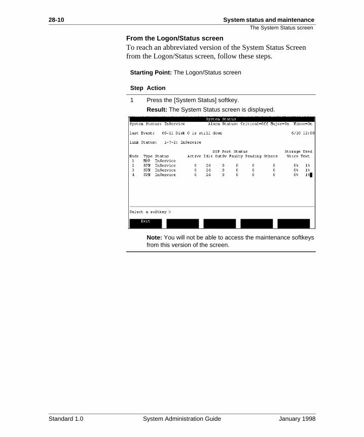
28-10 System status and maintenance The System Status screen
n
From the Logon/Status screenTo reach an abbreviated version of the System Status Screefrom the Logon/Status screen, follow these steps.Starting Point: The Logon/Status screen
Step Action
1 Press the [System Status] softkey.
Result: The System Status screen is displayed.
Note: You will not be able to access the maintenance softkeys from this version of the screen.
Standard 1.0 System Administration Guide January 1998
System status and maintenance 28-11The System Status screen
ter
in
re
.
Field descriptions The following fields appear on the System Status screen.
System Status
Description This field displays the current system status.
Possible status types
There are four possible status types.
InService This indicates the system is running.
CourtesyPending This indicates that the system isin the process of shutting down. This appears afusing the [Courtesy Down System] softkey. Incoming calls are directed to an attendant. Callsprogress are not interrupted. Each DSP port is courtesy disabled as it becomes idle. The softwaremains loaded.
CourtesyDown This indicates that the system hasshut down and is no longer operational or accepting calls, but the software remains loadedWhen the system is down, the [Courtesy Down System] softkey becomes [Activate System]. When the [Activate System] softkey is used, the system restarts.
Loading This indicates the system is loading software during bootup.
Standard 1.0 System Administration Guide January 1998
28-12 System status and maintenance The System Status screen
g 4
e
no
re
ort
.
Alarm Status
Description This indicates the state of each of the types of alarms described below.
Alarm types There are three possible alarm types.
Critical These alarms indicate a service-affectingproblem that requires immediate attention.
Major These alarms indicate a service-threateninproblem that may be allowed to persist for up to 2hours. If not attended to, the alarm could becomcritical.
Minor These alarms indicate a problem that has impact on the system or users.
For more details, see Chapter 29, “SEERs and Meridian Mail Alarms”.
Alarm states Each alarm type can be in one of the following states.
Off This state indicates that there are no new alarms. This does not necessarily mean that theare no error conditions.
On This status indicates that one or more alarm situations were detected.
Unk This indicates that the status is unknown.
Last Event
Description This is the most recent system event or error rep(SEER) logged.
Link Status
Description This is the state of the AML link to the Meridian 1
Link states The link can be in one of the following states:
InService This indicates that the link is operational.
Faulty This state indicates that a hardware problem exists but that the data port remains operational.
Standard 1.0 System Administration Guide January 1998
System status and maintenance 28-13The System Status screen
e n
s
.
s
is
Node
Description This is the node number.
Type
Description This is the type of node.
Status
Description This is the status of the nodes in your system.
Note: The status at this level does not indicate thstatus of a given card on the node. For informatioon cards, see “The Card Status screen” on page 28-21.
Node states InService This state indicates that the node is operational.
Unequipped This indicates that the node has not been defined in the hardware database. Refer toSystem Administration Tools (NTP 555-7001-305) for instructions on modifying the hardware database.
Faulty This indicates that a hardware problem wadetected or a critical program on the node is not operational.
OutOfService This indicates that the node is no longer operational as a result of a forced disable
Loading This state indicates that the node is currently starting up and loading software into memory.
ShuttingDown This state indicates that the node ibeing put out of service.
Booting This indicates that the operating system being loaded on the node.
Standard 1.0 System Administration Guide January 1998
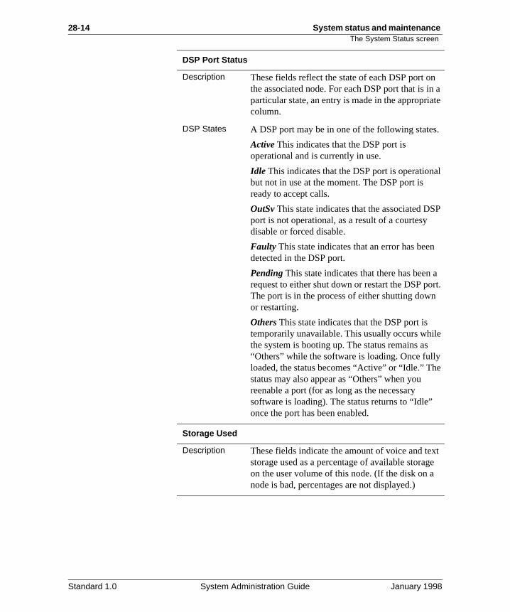
28-14 System status and maintenance The System Status screen
n n a te
.
al
P
a rt.
e
e
t e
DSP Port Status
Description These fields reflect the state of each DSP port othe associated node. For each DSP port that is iparticular state, an entry is made in the appropriacolumn.
DSP States A DSP port may be in one of the following states
Active This indicates that the DSP port is operational and is currently in use.
Idle This indicates that the DSP port is operationbut not in use at the moment. The DSP port is ready to accept calls.
OutSv This state indicates that the associated DSport is not operational, as a result of a courtesy disable or forced disable.
Faulty This state indicates that an error has beendetected in the DSP port.
Pending This state indicates that there has been request to either shut down or restart the DSP poThe port is in the process of either shutting downor restarting.
Others This state indicates that the DSP port is temporarily unavailable. This usually occurs whilthe system is booting up. The status remains as “Others” while the software is loading. Once fullyloaded, the status becomes “Active” or “Idle.” Thstatus may also appear as “Others” when you reenable a port (for as long as the necessary software is loading). The status returns to “Idle” once the port has been enabled.
Storage Used
Description These fields indicate the amount of voice and texstorage used as a percentage of available storagon the user volume of this node. (If the disk on anode is bad, percentages are not displayed.)
Standard 1.0 System Administration Guide January 1998
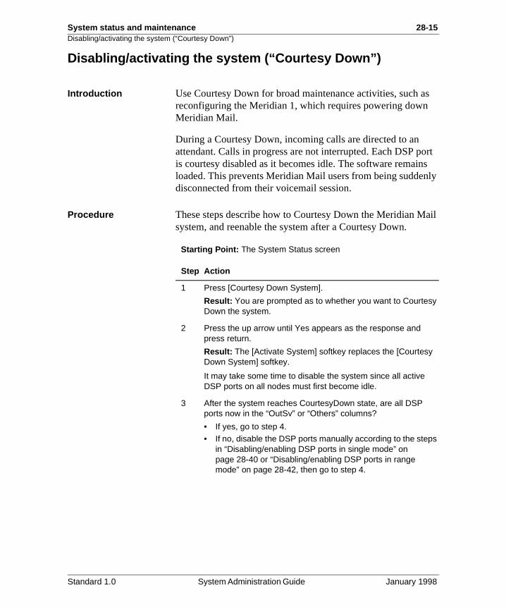
System status and maintenance 28-15Disabling/activating the system (“Courtesy Down”)
s
ort s ly
ail
Disabling/activating the system (“Courtesy Down”)
Introduction Use Courtesy Down for broad maintenance activities, such areconfiguring the Meridian 1, which requires powering downMeridian Mail.
During a Courtesy Down, incoming calls are directed to an attendant. Calls in progress are not interrupted. Each DSP pis courtesy disabled as it becomes idle. The software remainloaded. This prevents Meridian Mail users from being suddendisconnected from their voicemail session.
Procedure These steps describe how to Courtesy Down the Meridian Msystem, and reenable the system after a Courtesy Down.
Starting Point: The System Status screen
Step Action
1 Press [Courtesy Down System].
Result: You are prompted as to whether you want to Courtesy Down the system.
2 Press the up arrow until Yes appears as the response and press return.
Result: The [Activate System] softkey replaces the [Courtesy Down System] softkey.
It may take some time to disable the system since all active DSP ports on all nodes must first become idle.
3 After the system reaches CourtesyDown state, are all DSP ports now in the “OutSv” or “Others” columns?
• If yes, go to step 4.• If no, disable the DSP ports manually according to the steps
in “Disabling/enabling DSP ports in single mode” on page 28-40 or “Disabling/enabling DSP ports in range mode” on page 28-42, then go to step 4.
Standard 1.0 System Administration Guide January 1998
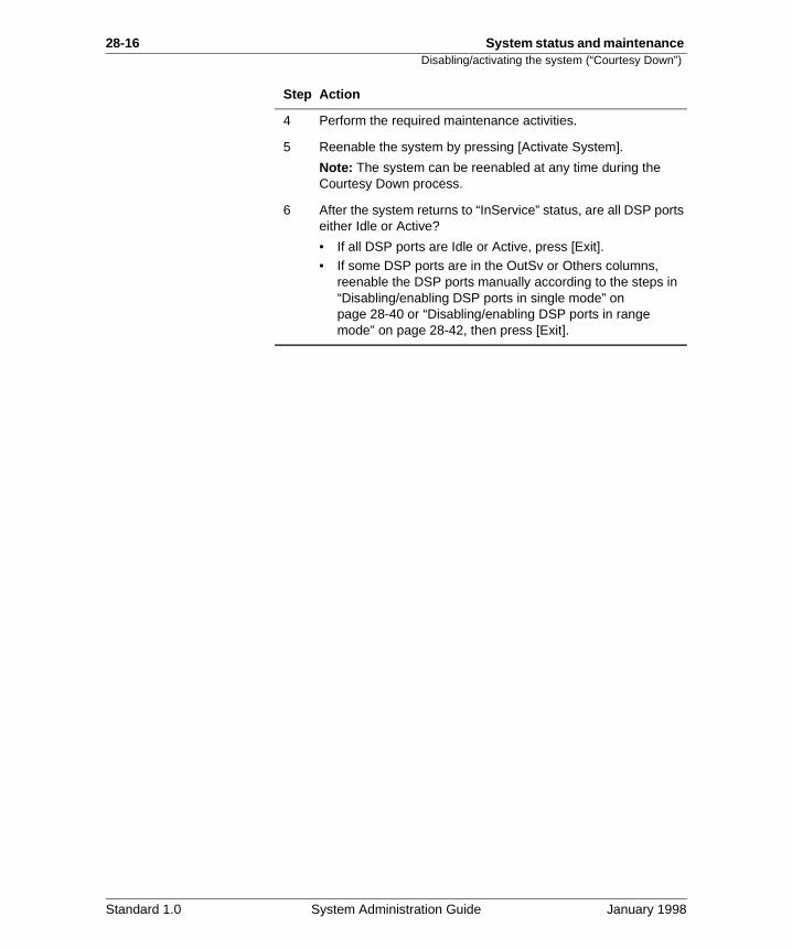
28-16 System status and maintenance Disabling/activating the system (“Courtesy Down”)
4 Perform the required maintenance activities.
5 Reenable the system by pressing [Activate System].
Note: The system can be reenabled at any time during the Courtesy Down process.
6 After the system returns to “InService” status, are all DSP ports either Idle or Active?
• If all DSP ports are Idle or Active, press [Exit].• If some DSP ports are in the OutSv or Others columns,
reenable the DSP ports manually according to the steps in “Disabling/enabling DSP ports in single mode” on page 28-40 or “Disabling/enabling DSP ports in range mode” on page 28-42, then press [Exit].
Step Action
Standard 1.0 System Administration Guide January 1998
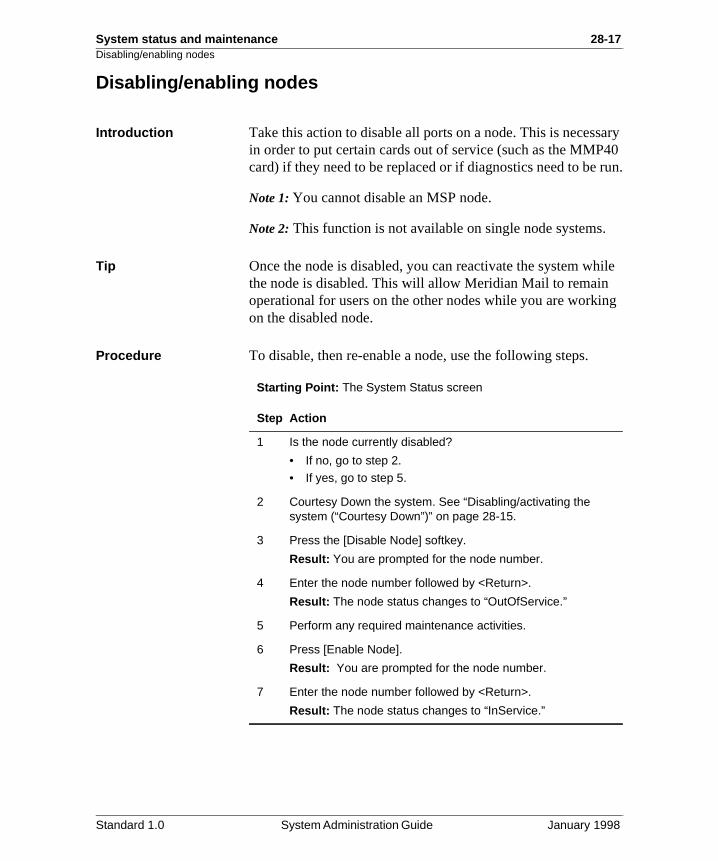
System status and maintenance 28-17Disabling/enabling nodes
ary 40
run.
ile
ng
Disabling/enabling nodes
Introduction Take this action to disable all ports on a node. This is necessin order to put certain cards out of service (such as the MMPcard) if they need to be replaced or if diagnostics need to be
Note 1: You cannot disable an MSP node.
Note 2: This function is not available on single node systems.
Tip Once the node is disabled, you can reactivate the system whthe node is disabled. This will allow Meridian Mail to remain operational for users on the other nodes while you are workion the disabled node.
Procedure To disable, then re-enable a node, use the following steps.
Starting Point: The System Status screen
Step Action
1 Is the node currently disabled?
• If no, go to step 2.
• If yes, go to step 5.
2 Courtesy Down the system. See “Disabling/activating the system (“Courtesy Down”)” on page 28-15.
3 Press the [Disable Node] softkey.
Result: You are prompted for the node number.
4 Enter the node number followed by <Return>.
Result: The node status changes to “OutOfService.”
5 Perform any required maintenance activities.
6 Press [Enable Node].
Result: You are prompted for the node number.
7 Enter the node number followed by <Return>.
Result: The node status changes to “InService.”
Standard 1.0 System Administration Guide January 1998
28-18 System status and maintenance Courtesy disabling/enabling ports
lar
es ail il
is eed
Courtesy disabling/enabling ports
Introduction When you courtesy disable ports, incoming calls on a particunode are directed to an attendant. Calls in progress are not interrupted. Each DSP port is courtesy disabled as it becomidle. The software remains loaded. This prevents Meridian Musers from being suddenly disconnected from their voicemasession.
Take this action to courtesy disable all ports on a node. Thisnecessary in order to put certain cards out of service if they nto be replaced or if diagnostics need to be run.
Note: This function is not available on single node systems.
Procedure To courtesy disable ports, then re-enable them, use the following steps.
Starting Point: The System Status screen
Step Action
1 Is the node currently disabled?
• If no, go to step 2.• If yes, go to step 4.
2 Press [Courtesy Disable Ports].
Result: You are prompted for the number of an in-service node.
3 Enter the node number followed by <Return>.
Result: As the DSP ports for the node become free, the System Status screen will show the DSP ports for that node as being in “Pending” then in “OutSv” state.
4 Perform any required maintenance activities.
5 Press [Enable Node].
Result: You are prompted for the number of an out-of-service node.
6 Enter the node number followed by <Return>.
Result: The status of the DSP ports for the node changes to “Others” and then to “Idle.”
Standard 1.0 System Administration Guide January 1998
System status and maintenance 28-19
Section B: Card Status
In this section
Overview 28-20
The Card Status screen 28-21
Enabling/disabling cards 28-27
Running out-of-service diagnostics 28-28
Standard 1.0 System Administration Guide January 1998
28-20 System status and maintenance Overview
nce
, and
ple, ee
ct rd
f-
e e
not
Overview
Introduction The Card Status option on the System Status and Maintenamenu allows you to check the status of the cards on your system, enable or disable voice processor cards as requiredrun out-of-service diagnostics on a disabled or faulty card.
To disable cards that are not voice processor cards (for examan MMP40 card), you must use the disable-node function (s“Disabling/enabling nodes” on page 28-17).
When to use this feature
The Card Status screen can be used to
• check the status of the cards in your system if you suspethat your system is not performing properly (see “The CaStatus screen” on page 28-21)
The Card Status screen will show you if any of the cardsare faulty or disabled. If a card is faulty or disabled, per-form a diagnostic check on the card (see “Running out-oservice diagnostics” on page 28-28).
• disable a voice processor card to perform a diagnostic check, or to replace the card (see “Enabling/disabling cards” on page 28-27)
Note: Only voice processor cards can be disabled through thCard Status screen. To disable other cards, you must use thdisable-node function (see “Disabling/enabling nodes” on page 28-17).
• perform a diagnostic check on a card that you suspect isworking properly, or on a new card that has just been installed in your system (see “Running out-of-service diagnostics” on page 28-28)
Standard 1.0 System Administration Guide January 1998
System status and maintenance 28-21The Card Status screen
e on ards
n
it.
The Card Status screen
Introduction The Card Status screen displays the operational status of thcards in your system. The enable/disable softkeys displayedthis screen are used to enable and disable voice processor conly.
If you suspect a problem with your system hardware, you cause this screen to check that all the cards on a node are functioning properly. You can also run diagnostics on a cardfrom the Card Status screen.
Before running diagnostics on a card, you must first disable See “Enabling/disabling cards” on page 28-27.
Reaching the screen To check card status, use the following steps.
Starting Point: The Main Menu
Step Action
1 Select System Status and Maintenance.
Result: The System Status and Maintenance menu is displayed.
2 Select Card Status
3 Do you have a multinode system?
• If yes, you are prompted for the node number. Enter the node number followed by <Return>.
Result: The Card Status screen for the node you requested is displayed.
• If no, you are immediately taken to the Card Status screen.
Standard 1.0 System Administration Guide January 1998
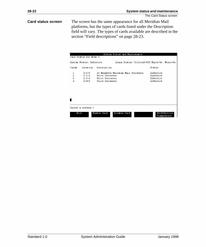
28-22 System status and maintenance The Card Status screen
he
Card status screen The screen has the same appearance for all Meridian Mail platforms, but the types of cards listed under the Descriptionfield will vary. The types of cards available are described in tsection “Field descriptions” on page 28-23.
Standard 1.0 System Administration Guide January 1998
System status and maintenance 28-23The Card Status screen
Field descriptions The following fields appear on the Card Status screen.
System Status
Description This field displays the current system status.
Possible status types
There are four possible status types.
InService This indicates the system is running.
CourtesyPending This indicates that the system isin the process of shutting down.
CourtesyDown This indicates that the system hasshut down and is no longer operational or accepting calls.
Loading This indicates the system is loading software during bootup.
Standard 1.0 System Administration Guide January 1998
28-24 System status and maintenance The Card Status screen
g 4
e
no
are
ing
Alarm Status
Description This indicates the state of each of the types of alarms described below.
Alarm types There are three possible alarm types.
Critical These alarms indicate a service-affectingproblem that requires immediate attention.
Major These alarms indicate a service-threateninproblem that may be allowed to persist for up to 2hours. If not attended to, the alarm could becomcritical.
Minor These alarms indicate a problem that has impact on the system or users.
For more details, see Chapter 29, “SEERs and Meridian Mail Alarms”.
Alarm states Each alarm type can be in one of the following states.
Off This state indicates that there are no new alarms. This does not necessary mean that thereno error conditions.
On This status indicates that one or more alarm situations were detected.
Unk This indicates that the status is unknown.
Card #
Description This is the number of each card in the selected node.
Location
Description This is the physical location (Node-Card-Port) ofeach card in the selected node.
Description
Description This is the type of card at that location.
Valid entries The possible card types are listed here. Dependon your system type, you will not see all of thesecards on your system.
Standard 1.0 System Administration Guide January 1998
System status and maintenance 28-25The Card Status screen
, r
ide
16 Megabyte Meridian Mail processor (MMP40)This is the Meridian Mail processor (CPU) card which includes a 24 MHz 68040 processor, 16 Mbytes of memory, up to two RS-232 serial portsand a SCSI interface processor. It is displayed foMMP40 systems.
RS232 Service Module (RSM)This is an RS-232 card (for non-EC systems).
High Speed BusThis is the high-speed bus (also called HABC forHigh Availability Bus Controller).
Network Voice Processor (NVP) This is the 16 kbyte network voice processor.
32K Network Voice Processor (NVP32) This is the 32 kbyte network voice processor.
Utility (UTIL)This card, on EC systems only, contains a high speed bus. It also includes four auxiliary RS-232ports. (1- to 4-node systems require one of thesecards; 5-node systems with 60 or more ports require two of these cards.)
Voice Processor (VP4/VP8)These cards are voice processor cards that provfour and eight channels respectively.
EmptyThe card slot is empty.
Standard 1.0 System Administration Guide January 1998
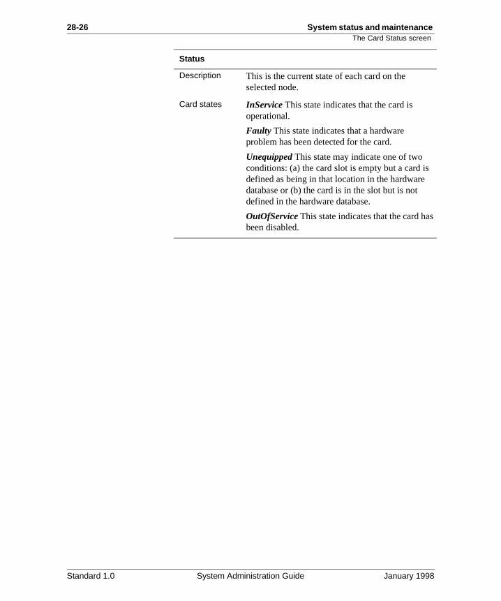
28-26 System status and maintenance The Card Status screen
s
s
Status
Description This is the current state of each card on the selected node.
Card states InService This state indicates that the card is operational.
Faulty This state indicates that a hardware problem has been detected for the card.
Unequipped This state may indicate one of two conditions: (a) the card slot is empty but a card idefined as being in that location in the hardwaredatabase or (b) the card is in the slot but is not defined in the hardware database.
OutOfService This state indicates that the card habeen disabled.
Standard 1.0 System Administration Guide January 1998
System status and maintenance 28-27Enabling/disabling cards
ard),
Enabling/disabling cards
Introduction Only voice processor cards can be disabled from the Card Status screen. To disable other cards (such as the MMP40 cyou must use the disable-node function (see “Disabling/enabling nodes” on page 28-17).
Procedure Starting Point: The Card Status screen
Step Action
1 Press [Disable Card].
Result: You are prompted for the number of the card you wish to disable.
Note: You can only disable voice processor cards from this screen.
2 Enter the number of the card followed by <Return>.
Result: The system may take some time disabling the card. The message “WORKING...” will be displayed during this interval. The card is disabled when its status changes to “OutOfService”.
3 Perform diagnostics on the card as described in “Running out-of-service diagnostics” on page 28-28.
4 Press [Enable Card].
Result: You are prompted for the number of an out-of-service card.
5 Enter the number of an out-of-service card followed by <Return>.
Result: The system may take some time enabling the card. The message “WORKING...” will be displayed during this interval. The card is enabled when its status changes to “InService”.
Standard 1.0 System Administration Guide January 1998
28-28 System status and maintenance Running out-of-service diagnostics
on
Running out-of-service diagnostics
Introduction If you suspect a card is faulty, run out-of-service diagnosticsthe card. If the test shows the card is faulty, it is assigned a “Faulty” status which can be observed on the Card Status screen.
Procedure Starting Point: The Card Status screen
Step Action
1 Are you running out-of-service diagnostics on a voice processor card?
• If yes, disable the voice processor card according to the instructions in “Enabling/disabling cards” on page 28-27.
• If no, disable the node according to the instructions in “Disabling/enabling nodes” on page 28-17.
2 Press [OutOfService Diagnostics].
Result: You are prompted for the number of an out-of-service card.
3 Enter the card number followed by <Return>.
Result: The message “WORKING...” will be displayed while diagnostics are running. When diagnostics are completed, the result is displayed in a screen message.
IF diagnostics THEN
fail the card status will be “Faulty.” There is a hardware problem with the card and it should be replaced. Refer to the Installation and Maintenance Guide for your platform.
pass the card can be reenabled.
pass on a card that was already in a “Faulty” state
the card is put in “OutOfService” state.
Standard 1.0 System Administration Guide January 1998
System status and maintenance 28-29
Section C: DSP Port Status
In this section
Overview 28-30
The DSP Port Status screen 28-31
Detailed view of the DSP Port Status screen 28-38
Single mode and range mode 28-39
Disabling/enabling DSP ports in single mode 28-40
Disabling/enabling DSP ports in range mode 28-42
Standard 1.0 System Administration Guide January 1998
28-30 System status and maintenance Overview
nal
ice ns. s or
he
e
e
Overview
Introduction The DSP Port Status screen allows you to view the operatiostatus of the DSP ports in the system and enable or disable individual ports when necessary.
Definition: xxxxxxx DSP
A DSP is a Digital Signal Processor which is located on a voprocessor card. Each DSP supports two physical port locatioAs a result, each DSP can support two voice processing portone multimedia port (for multimedia services, both physical ports of a DSP are used to configure one multimedia port). Tconfigured port (voice or multimedia) is referred to as a DSPport or just as a port.
When to use this feature
You would use this feature to
• check the status of DSP ports (are any ports Faulty or OutOfService?)
• disable a port prior to modifying information relating to thport on the Channel Allocation Table
If you are dedicating a port, or assigning a specific outbound service to a port, you must show this on the Channel Allocation Table. A port must be disabled beforany information relating to it can be modified on the Channel Allocation Table.
• reenable a port that was taken out of service
Standard 1.0 System Administration Guide January 1998
System status and maintenance 28-31The DSP Port Status screen
m ns:
The DSP Port Status screen
Introduction This section describes the DSP Port Status screen.
The DSP Port Status screen that you access from the SysteStatus and Maintenance menu provides the following functio
• Enable Port (see pages 28-40 to 28-42)
• Disable Port (see pages 28-40 to 28-42)
• Courtesy Disable Port (see pages 28-40 to 28-42)
• Change to Range Mode/Change to Single Mode (see “Single mode and range mode” on page 28-39)
Reaching the screen—two ways
There are two ways to reach two different versions of the System Status screen.
From the Main MenuTo reach the DSP Port Status screen from the Main Menu, follow these steps.
Starting Point: The Main Menu
Step Action
1 Select System Status and Maintenance.
Result: The System Status and Maintenance menu is displayed.
2 Select DSP Port Status.
Standard 1.0 System Administration Guide January 1998
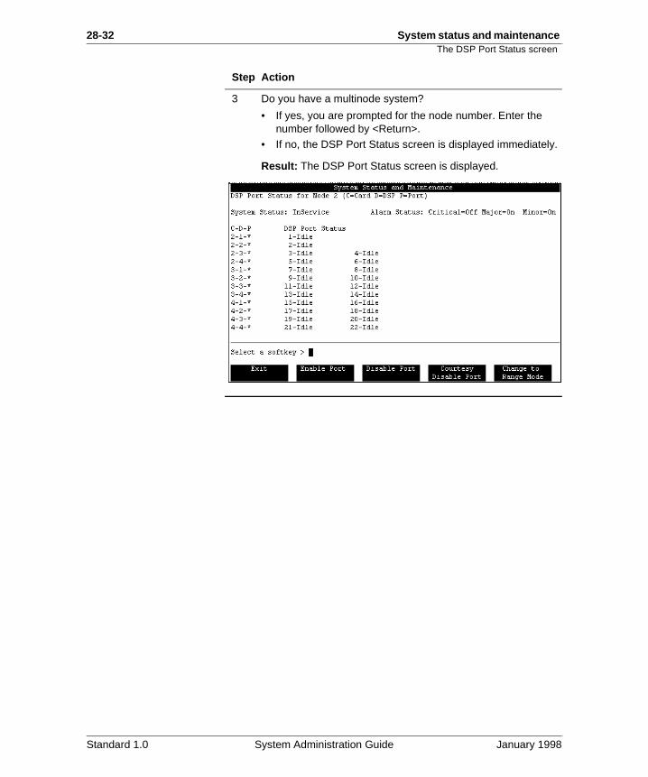
28-32 System status and maintenance The DSP Port Status screen
3 Do you have a multinode system?
• If yes, you are prompted for the node number. Enter the number followed by <Return>.
• If no, the DSP Port Status screen is displayed immediately.
Result: The DSP Port Status screen is displayed.
Step Action
Standard 1.0 System Administration Guide January 1998
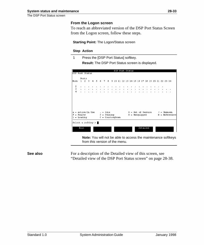
System status and maintenance 28-33The DSP Port Status screen
een
.
From the Logon screenTo reach an abbreviated version of the DSP Port Status Scrfrom the Logon screen, follow these steps.
Starting Point: The Logon/Status screen
See also For a description of the Detailed view of this screen, see “Detailed view of the DSP Port Status screen” on page 28-38
Step Action
1 Press the [DSP Port Status] softkey.
Result: The DSP Port Status screen is displayed.
Note: You will not be able to access the maintenance softkeys from this version of the menu.
Standard 1.0 System Administration Guide January 1998
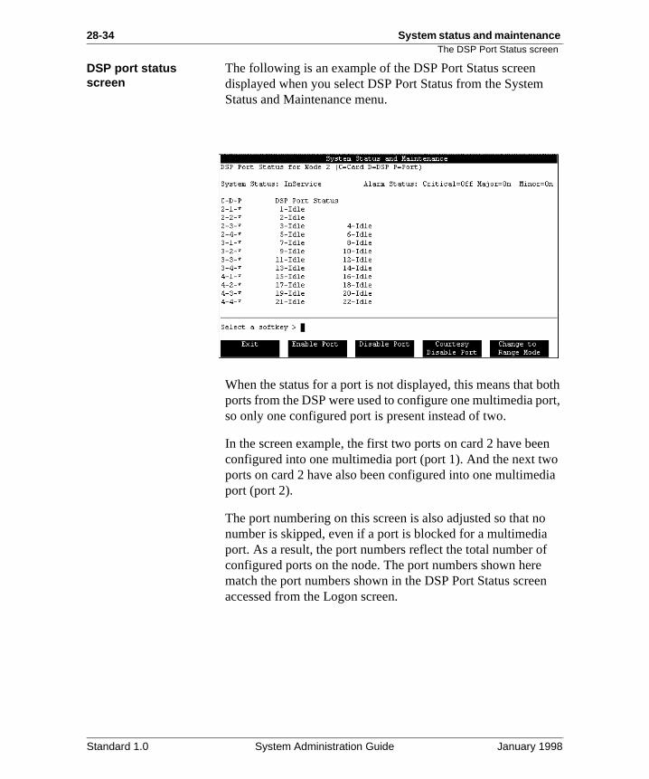
28-34 System status and maintenance The DSP Port Status screen
oth ort,
n o ia
o f n
DSP port status screen
The following is an example of the DSP Port Status screen displayed when you select DSP Port Status from the SystemStatus and Maintenance menu.
When the status for a port is not displayed, this means that bports from the DSP were used to configure one multimedia pso only one configured port is present instead of two.
In the screen example, the first two ports on card 2 have beeconfigured into one multimedia port (port 1). And the next twports on card 2 have also been configured into one multimedport (port 2).
The port numbering on this screen is also adjusted so that nnumber is skipped, even if a port is blocked for a multimediaport. As a result, the port numbers reflect the total number oconfigured ports on the node. The port numbers shown herematch the port numbers shown in the DSP Port Status screeaccessed from the Logon screen.
Standard 1.0 System Administration Guide January 1998
System status and maintenance 28-35The DSP Port Status screen
g 4
e
no
re
Field descriptions The following fields appear on the DSP Port Status screen.
System Status
Description This field displays the current system status.
Possible status types
There are four possible status types.
InService This indicates the system is running.
CourtesyPending This indicates that the system isin the process of shutting down.
CourtesyDown This indicates that the system hasshut down and is no longer operational or accepting calls.
Loading This indicates the system is loading software during bootup.
Alarm Status
Description This indicates the state of each of the types of alarms described below.
Alarm types There are three possible alarm types.
Critical These alarms indicate a service-affectingproblem that requires immediate attention.
Major These alarms indicate a service-threateninproblem that may be allowed to persist for up to 2hours. If not attended to, the alarm could becomcritical.
Minor These alarms indicate a problem that has impact on the system or users.
For more details, see Chapter 29, “SEERs and Meridian Mail Alarms”.
Alarm states Each alarm type can be in one of the following states.
Off This state indicates that there are no new alarms. This does not necessarily mean that theare no error conditions.
On This status indicates that one or more alarm situations were detected.
Unk This indicates that the status is unknown.
Standard 1.0 System Administration Guide January 1998
28-36 System status and maintenance The DSP Port Status screen
r
is l
t).
C-D-P (location)
Description This is the physical location of each DSP port onthe selected node (card number-DSP-port).
DSP Port Status
Description This is the current state of each DSP port. The status can be one of the following.
DSP states Active This status indicates that the DSP port is operational and in use.
Idle This status indicates that the DSP port is operational but not currently in use.
Faulty This status indicates that the system has detected an error in the DSP port.
UnEquipped This status indicates that the DSP port is not defined in the hardware database. Fomore information about modifying the hardware database, refer to System Administration Tools (NTP 555-7001-305).
POutService This status indicates that the DSP port is in the process of shutting down. If [Courtesy Disable Port] was used, the DSP port still active while in this state. Once the active calis disconnected, the port status will be OutOfService.
OutOfService This status indicates that the DSP port is no longer operational as a result of a courtesy disable or forced disable.
NoResources This status indicates a transition state that occurs during the initial stages of software loading (after a request to enable a porWhen software begins to load, the port is initiallyin this state, followed by Loading and then Idle, once the software has finished loading.
Standard 1.0 System Administration Guide January 1998
System status and maintenance 28-37The DSP Port Status screen
is d
t
of
s l .
DSP states (continued)
Loading This status indicates that the DSP port currently starting up after a request to enable anthat the necessary software is loading.
CtsyDown This status indicates that the DSP poris down as a result of a Courtesy Down System.
PCtsyDown This status indicates that the DSP port is in the process of shutting down as a resulta Courtesy Down System, pending the disconnection of any active calls. The DSP port istill active while in this state. Once the active calis disconnected, the port status will be CtsyDown
Standard 1.0 System Administration Guide January 1998
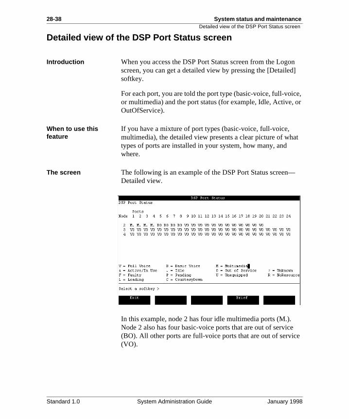
28-38 System status and maintenance Detailed view of the DSP Port Status screen
n ]
e, or
at
e
Detailed view of the DSP Port Status screen
Introduction When you access the DSP Port Status screen from the Logoscreen, you can get a detailed view by pressing the [Detailedsoftkey.
For each port, you are told the port type (basic-voice, full-voicor multimedia) and the port status (for example, Idle, Active, OutOfService).
When to use this feature
If you have a mixture of port types (basic-voice, full-voice, multimedia), the detailed view presents a clear picture of whtypes of ports are installed in your system, how many, and where.
The screen The following is an example of the DSP Port Status screen—Detailed view.
In this example, node 2 has four idle multimedia ports (M.). Node 2 also has four basic-voice ports that are out of service(BO). All other ports are full-voice ports that are out of servic(VO).
Standard 1.0 System Administration Guide January 1998
System status and maintenance 28-39Single mode and range mode
le
le a
o
Single mode and range mode
Description Single mode allows you to enable, disable, or courtesy disabindividual DSP ports one at a time.
Range mode allows you to enable, disable, or courtesy disabcontiguous range of DSP ports at once. For example, it will work if you need to disable ports 3 to 7, but not if you need tdisable ports 1, 3, and 7.
Standard 1.0 System Administration Guide January 1998
28-40 System status and maintenance Disabling/enabling DSP ports in single mode
ne
en t. e
le
to y.
ted
the
Disabling/enabling DSP ports in single mode
Introduction This section describes how to disable ports in single mode (oport at a time).
Note: If a port is faulty and you attempt to disable it, the scremessage will be the same as if you are disabling an idle porHowever, the port will not be disabled. A faulty port cannot bdisabled or enabled.
Disable Port versus Courtesy Disable Port
The procedure in this section asks you to check if a port is idor active before disabling it. If a port is idle, you can use the Disable Port softkey. If a port is active (it is processing a callMeridian Mail), you can use the Courtesy Disable Port softke
The courtesy disable method waits until the call is disconnecbefore disabling the port. This prevents users from being disconnected suddenly from Meridian Mail.
If you use the Disable Port softkey to disable an active port, caller is abruptly disconnected.
Standard 1.0 System Administration Guide January 1998
System status and maintenance 28-41Disabling/enabling DSP ports in single mode
Procedure Starting Point: The System Status and Maintenance menu
Step Action
1 Select DSP Port Status.
• If you have a single node system, the DSP Port Status screen is displayed. Go to step 3.
• If you have a multinode system, go to step 2.
2 For multinode systems, enter the number of the node on which the DSP port resides, followed by <Return>.
Result: The DSP Port Status screen is displayed.
3 Is the DSP port active?
• If yes, press [Courtesy Disable Port].
• If no, press [Disable Port].
Result: You are prompted for the number of a DSP port.
4 Enter the DSP port number followed by <Return>.
Result: The system may take some time to disable the port. In the case of a courtesy disable, the system waits until the active call has been disconnected.
The system displays a message informing you that the port is being disabled. The message “WORKING...” may also be displayed.
While the port is being disabled, its status will change to POutService and then to OutOfService.
5 Perform any required maintenance activities.
6 Press [Enable Port].
Result: You are prompted for the number of a DSP port.
7 Enter the DSP port number followed by <Return>.
Result: The system may take some time to enable the port. The system displays a message informing you that the port is being enabled. The message “WORKING...” may also be displayed.
While the port is being enabled, its status will change to “Loading” and then to “Idle.”
8 Press [Exit] to return to the System Status and Maintenance menu.
Standard 1.0 System Administration Guide January 1998
28-42 System status and maintenance Disabling/enabling DSP ports in range mode
nge ling
en t. e
re tive
ted
the
Disabling/enabling DSP ports in range mode
Introduction Range mode allows you to disable or enable a contiguous raof DSP ports at once. This saves time over disabling or enabports one at a time.
Note: If a port is faulty and you attempt to disable it, the scremessage will be the same as if you are disabling an idle porHowever, the port will not be disabled. A faulty port cannot bdisabled or enabled.
Disable Port versus Courtesy Disable Port
The procedure in this section asks you to check if the ports aidle or active before disabling them. If the ports are idle, youcan use the Disable Port softkey. If some of the ports are ac(they are processing calls to Meridian Mail), you can use theCourtesy Disable Port softkey.
The courtesy disable method waits until the call is disconnecbefore disabling the port. This prevents users from being disconnected suddenly from Meridian Mail.
If you use the Disable Port softkey to disable an active port, caller is abruptly disconnected.
Standard 1.0 System Administration Guide January 1998
System status and maintenance 28-43Disabling/enabling DSP ports in range mode
Procedure Starting Point: The System Status and Maintenance menu
Step Action
1 Select DSP Port Status.
• If you have a single node system, the DSP Port Status screen is displayed. Go to step 3.
• If you have a multinode system, go to step 2.
2 For multinode systems, enter the number of the node on which the DSP port resides, followed by <Return>.
Result: The DSP Port Status screen is displayed.
3 Press [Change to Range Mode].
Result: The softkey now shows [Change to Single Mode].
4 Are DSP ports active?
• If yes, press [Courtesy Disable Port].
• If no, press [Disable Port].
Result: You are prompted for the number of the first DSP port in the range you want to force disable or courtesy disable.
5 Enter the number of the first DSP port in the range followed by <Return>.
Result: You are prompted for the number of the last DSP port in the range.
6 Enter the number of the last DSP port in the range followed by <Return>.
Result: The system will begin to disable the DSP ports. This may take some time. If you are courtesy disabling the ports, the system will wait for each port to become idle before it disables them.
While the ports are being disabled, their status will change to “POutService” and then to “OutOfService.” The message “WORKING...” may also be displayed at this time.
After the disabling is completed, the system displays a message indicating the number of ports that were successfully disabled, and the number of ports that could not be disabled.
7 Perform any required maintenance activities.
8 Press [Enable Port].
Result: You are prompted for the number of the first DSP port in the range of ports you wish to enable.
Standard 1.0 System Administration Guide January 1998
28-44 System status and maintenance Disabling/enabling DSP ports in range mode
9 Enter the number of the first DSP port followed by <Return>.
Result: You are prompted for the number of the last DSP port in the range.
10 Enter the number of the last DSP port followed by <Return>.
Result: The system may take some time enabling the ports. The system displays a message to inform you that the DSP ports are being enabled. While the ports are being enabled, their status will change to “Loading” and then to “Idle.”
After the enabling is completed, the system displays a message indicating the number of ports that were successfully enabled, and the number of ports that could not be enabled.
11 Press [Exit] to return to the System Status and Maintenance menu.
Step Action
Standard 1.0 System Administration Guide January 1998
Chapter 28
System status and maintenance 28-45Section D: Channel Allocation Table
In this section
Overview 28-46
The Channel Allocation Table 28-47
Modifying the Channel Allocation Table 28-59
Standard 1.0 System Administration Guide January 1998
28-46 System status and maintenanceOverview
nt
.
dd
(in to h a r
r it e
as
see
Overview
Introduction The Channel Allocation Table (CAT) allows you to
• view how channels are currently allocated across differequeues and services
• see what the distribution of port types is (the number of basic, full-voice, and multimedia ports)
• move agents from one queue to another as part of the procedure to dedicate a port
When to use this feature
Normally, you will not have to configure this table. When theMeridian Mail software is installed, the installation technicianconfigures the switch to match the Channel Allocation Table
This is also true when you perform a channel expansion (to anew agents). You generally do not have to modify the CAT because it is updated with the information that was providedduring the expansion.
However, when you move agents from one queue to anotherorder to dedicate them to a particular service), you will havemodify the CAT to show that the agent is now associated witdifferent queue and that the agent is dedicated to a particulaservice.
When to dedicate ports
Dedicating ports to a particular service reduces the overall efficiency of your port usage, so you should consider whetheis necessary to dedicate ports. Note that even when you havseparate queues set up for basic, full-voice, and multimedia ports, these ports can be shared for outbound services (suchRemote Notification and Fax Outcalling).
For more information about port types and dedicating ports, the section "Planning your configuration" on page 23-13.
Standard 1.0 System Administration Guide January 1998
System status and maintenance 28-47The Channel Allocation Table
on
ing
to y
asic, or
to ng
The Channel Allocation Table
Introduction The Channel Allocation Table (CAT) determines how agents the switch are associated with DSP ports on Meridian Mail.
Agents are identified by a terminal number (TN), an ACD directory number (DN), and a single call non-ringing (SCN) DN. Each DSP port must be associated with an existing ACDagent in the Meridian 1 database. This is to handle the queuof calls coming in to Meridian Mail, and to handle dial-out features such as Remote Notification and Delivery to Non-Users.
When to use When you move agents from one queue to another (in orderdedicate them to a particular service), you will have to modifthe CAT to indicate the ACD DN with which the agent is nowassociated, as well as the service to which it is dedicated.
Note that even when you have separate queues set up for bfull-voice, and multimedia ports, these ports can be shared foutbound services (such as Remote Notification and Fax Outcalling).
For a complete explanation of how to dedicate ports, and howdecide if you need to dedicate ports, see the section "Planniyour configuration" on page 23-13.
ATTENTION
The Channel Allocation Table (CAT) should only be configured by those who know how to program the switch.
Standard 1.0 System Administration Guide January 1998
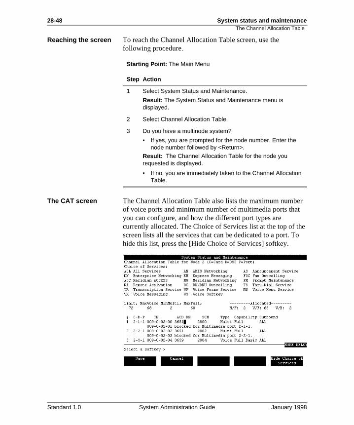
28-48 System status and maintenanceThe Channel Allocation Table
r
he o
Reaching the screen To reach the Channel Allocation Table screen, use the following procedure.
Starting Point: The Main Menu
The CAT screen The Channel Allocation Table also lists the maximum numbeof voice ports and minimum number of multimedia ports thatyou can configure, and how the different port types are currently allocated. The Choice of Services list at the top of tscreen lists all the services that can be dedicated to a port. Thide this list, press the [Hide Choice of Services] softkey.
Step Action
1 Select System Status and Maintenance.
Result: The System Status and Maintenance menu is displayed.
2 Select Channel Allocation Table.
3 Do you have a multinode system?
• If yes, you are prompted for the node number. Enter the node number followed by <Return>.
Result: The Channel Allocation Table for the node you requested is displayed.
• If no, you are immediately taken to the Channel Allocation Table.
Standard 1.0 System Administration Guide January 1998
System status and maintenance 28-49The Channel Allocation Table
ted is
be y d
pe
How port information is presented
Ports that are configured to support multimedia services (multimedia ports) require the use of both DSP ports supporby a DSP. The location of the first port supported by the DSPconsidered the location of the multimedia port. The second physical port location supported by the DSP is considered toblocked for the multimedia port. This is reflected in the CAT ba row following the multimedia port with the message “blockefor Multimedia port C-D-P,” where C-D-P is the “Card-DSP-Port” number of the multimedia port.
The number of DSP ports on a system may be very large. Therefore, when you choose to view the CAT on a multinodesystem, you are prompted for a node number to limit the scoto one node at a time. The CAT screen then displays information for that node.
Standard 1.0 System Administration Guide January 1998
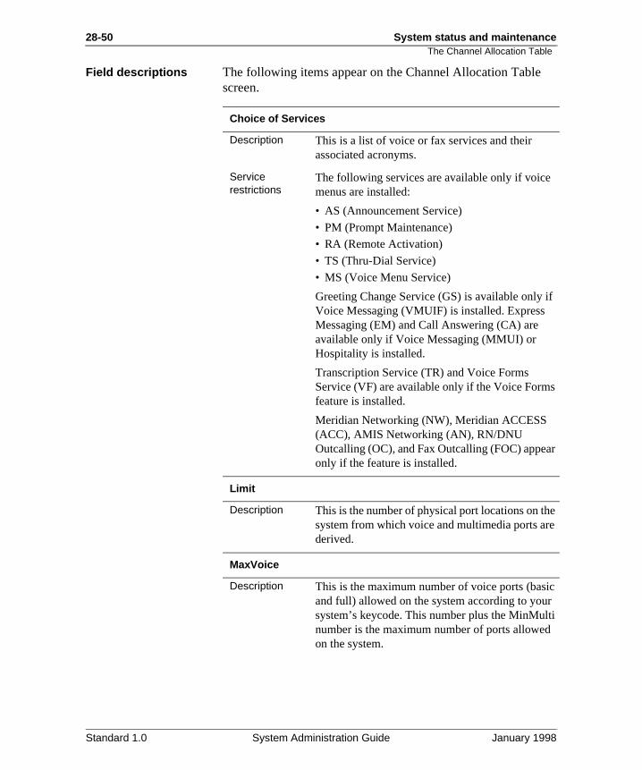
28-50 System status and maintenanceThe Channel Allocation Table
if
s
r
e e
ic r ti
Field descriptions The following items appear on the Channel Allocation Tablescreen.
Choice of Services
Description This is a list of voice or fax services and their associated acronyms.
Service restrictions
The following services are available only if voicemenus are installed:
• AS (Announcement Service)
• PM (Prompt Maintenance)
• RA (Remote Activation)
• TS (Thru-Dial Service)
• MS (Voice Menu Service)
Greeting Change Service (GS) is available only Voice Messaging (VMUIF) is installed. Express Messaging (EM) and Call Answering (CA) are available only if Voice Messaging (MMUI) or Hospitality is installed.
Transcription Service (TR) and Voice Forms Service (VF) are available only if the Voice Formfeature is installed.
Meridian Networking (NW), Meridian ACCESS (ACC), AMIS Networking (AN), RN/DNU Outcalling (OC), and Fax Outcalling (FOC) appeaonly if the feature is installed.
Limit
Description This is the number of physical port locations on thsystem from which voice and multimedia ports arderived.
MaxVoice
Description This is the maximum number of voice ports (basand full) allowed on the system according to yousystem’s keycode. This number plus the MinMulnumber is the maximum number of ports allowedon the system.
Standard 1.0 System Administration Guide January 1998
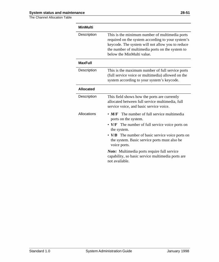
System status and maintenance 28-51The Channel Allocation Table
’s
n
MinMulti
Description This is the minimum number of multimedia portsrequired on the system according to your systemkeycode. The system will not allow you to reducethe number of multimedia ports on the system tobelow the MinMulti value.
MaxFull
Description This is the maximum number of full service ports(full service voice or multimedia) allowed on the system according to your system’s keycode.
Allocated
Description This field shows how the ports are currently allocated between full service multimedia, full service voice, and basic service voice.
Allocations • M/F The number of full service multimedia ports on the system.
• V/F The number of full service voice ports onthe system.
• V/B The number of basic service voice ports othe system. Basic service ports must also be voice ports.
Note: Multimedia ports require full service capability, so basic service multimedia ports are not available.
Standard 1.0 System Administration Guide January 1998
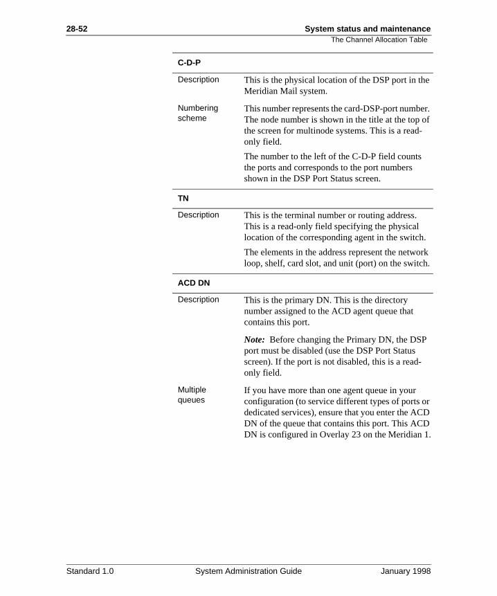
28-52 System status and maintenanceThe Channel Allocation Table
e
er. of -
.
rk .
r D
.
C-D-P
Description This is the physical location of the DSP port in thMeridian Mail system.
Numbering scheme
This number represents the card-DSP-port numbThe node number is shown in the title at the top the screen for multinode systems. This is a readonly field.
The number to the left of the C-D-P field counts the ports and corresponds to the port numbers shown in the DSP Port Status screen.
TN
Description This is the terminal number or routing address. This is a read-only field specifying the physical location of the corresponding agent in the switch
The elements in the address represent the netwoloop, shelf, card slot, and unit (port) on the switch
ACD DN
Description This is the primary DN. This is the directory number assigned to the ACD agent queue that contains this port.
Note: Before changing the Primary DN, the DSPport must be disabled (use the DSP Port Status screen). If the port is not disabled, this is a read-only field.
Multiple queues
If you have more than one agent queue in your configuration (to service different types of ports odedicated services), ensure that you enter the ACDN of the queue that contains this port. This ACDDN is configured in Overlay 23 on the Meridian 1
Standard 1.0 System Administration Guide January 1998
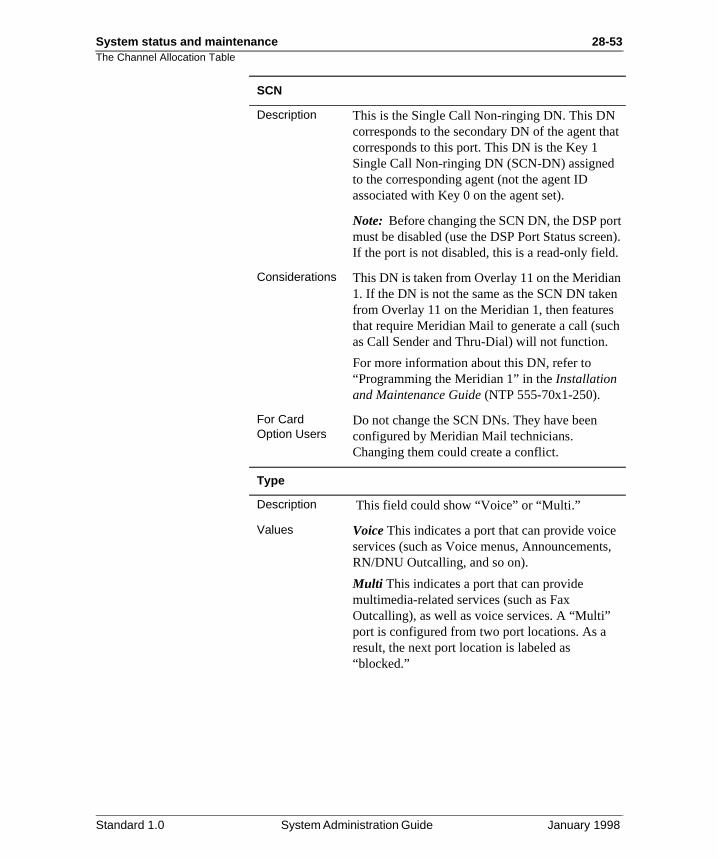
System status and maintenance 28-53The Channel Allocation Table
at
rt n).
.
n h
,
SCN
Description This is the Single Call Non-ringing DN. This DN corresponds to the secondary DN of the agent thcorresponds to this port. This DN is the Key 1 Single Call Non-ringing DN (SCN-DN) assigned to the corresponding agent (not the agent ID associated with Key 0 on the agent set).
Note: Before changing the SCN DN, the DSP pomust be disabled (use the DSP Port Status screeIf the port is not disabled, this is a read-only field
Considerations This DN is taken from Overlay 11 on the Meridian1. If the DN is not the same as the SCN DN takefrom Overlay 11 on the Meridian 1, then featuresthat require Meridian Mail to generate a call (sucas Call Sender and Thru-Dial) will not function.
For more information about this DN, refer to “Programming the Meridian 1” in the Installation and Maintenance Guide (NTP 555-70x1-250).
For Card Option Users
Do not change the SCN DNs. They have been configured by Meridian Mail technicians. Changing them could create a conflict.
Type
Description This field could show “Voice” or “Multi.”
Values Voice This indicates a port that can provide voiceservices (such as Voice menus, AnnouncementsRN/DNU Outcalling, and so on).
Multi This indicates a port that can provide multimedia-related services (such as Fax Outcalling), as well as voice services. A “Multi” port is configured from two port locations. As a result, the next port location is labeled as “blocked.”
Standard 1.0 System Administration Guide January 1998
28-54 System status and maintenanceThe Channel Allocation Table
ed
n
all
Capability
Description This field indicates the range of services supporton this port. The two ranges are “Basic” and “Full.” Note that all basic services can also run ofull service ports.
Basic services The following “Basic” services are available:
• ACC—Meridian ACCESS
• AS—Announcement Service
• MS—Voice Menu Service
• PM—Prompt Maintenance
• RA—Remote Activation
• TS—Thru-Dial Service
• VS—Voice Softkey
Full services “Full” services include all basic services plus thefollowing:
• VM—Voice Messaging
• EM—Express Messaging
• CA—Call Answering
• AN—AMIS Networking Agent
• OC—RN/DNU Outcalling
• HM—Hospitality Messaging
• CO—Post-Checkout Mailbox
• VF—Voice Forms Service
• TR—Transcription Service
• NW—Meridian Networking
• FOC—Fax Outcalling
Note: RN/DNU Outcalling supports Remote Notification and Delivery to Non-User features. Fax Outcalling supports Fax-on-Demand same-cdelivery and fax call-back delivery, Fax Information (FI), and Fax Item Maintenance (FIM).
Standard 1.0 System Administration Guide January 1998
System status and maintenance 28-55The Channel Allocation Table
d.
d
e
P
o
Outbound
Description When Meridian Mail makes an outbound call, it checks this column to see what ports can be use“ALL” indicates the port can be used for any outbound service (the port is shared for outbouncalls).
If you are dedicating the port to a particular servic(outbound or inbound service), enter the serviceacronym in this column. This will prevent Meridian Mail from using that port for another outbound service.
Example If you enter “OC” in this column for a particular port, the only outbound calls that can be made through this port are OC (RN/DNU) calls. At the same time, OC can use only this port to make outbound calls.
Note: You must disable the DSP port (see the DSPort Status screen) before changing the service associated with it.
Defaults The default is “ALL,” which indicates a shared DSP port.
Fax Outcalling considerations
A multimedia port can be shared for outbound services (enter “ALL” in the Outbound column).
You can achieve optimum traffic capacity for faxcalls on a multimedia port by dedicating the port tFax Outcalling and then using only the Fax Call Back method of delivery. For details, refer to theSite and Installation Planning Guide(NTP 555-70x1-200).
Meridian ACCESS considerations
If you enter ACC (Meridian ACCESS) in the Outbound column, a second field, Class, is displayed. For information and examples on howto configure ACCESS applications (for example,Meridian IVR), refer to the “Configuration examples” chapter in the Meridian ACCESS Configuration Guide (NTP 555-7001-315).
Standard 1.0 System Administration Guide January 1998
28-56 System status and maintenanceShould you dedicate ports?
e,
m. llers s it is
D
” t te
on
r of
rate
e
Should you dedicate ports?
Introduction When you dedicate a port to a particular service (for examplFax on Demand, Outcalling [RN/DNU]), that port cannot be used for any other service, including voice messaging (call answering, logging in to Meridian Mail). That port is reservedfor the service that you have assigned to it.
When ports are shared, they can be used for any service, including voice messaging.
Sharing your ports usually produces the most efficient systeWhen a port is dedicated, you can have a situation where caare unable to log in to Meridian Mail because all shared portare busy, while the dedicated port remains unused becausereserved for the particular service assigned to it.
Ports are dedicated for incoming calls through the use of ACqueues and the VSDN table.
Ports are dedicated for outgoing calls through the “Outboundcolumn on the CAT table. Ports that are assigned to differenqueues can be shared for outgoing calls (for example, RemoNotification and Fax Outcalling).
See also For a complete explanation of dedicated ports, see the secti"Planning your configuration" on page 23-13.
When would you dedicate a port to a particular service
If you need to ensure that you always have a certain numbeports free for a particular service (for example, an important voice menu, FOC, or OC), then you may decide you need todedicate ports to that service.
Dedicating ports for basic, full-voice, and multimedia services
If you have a mixture of port types (basic service, full servicevoice, and multimedia ports), then you need to set up a sepaACD queue for each port type. In effect, the ports become dedicated to a specific level of service, for incoming calls. Thseparate queues ensure that a call made to Meridian Mail isconnected to a port that is capable of providing the service
Standard 1.0 System Administration Guide January 1998
System status and maintenance 28-57Should you dedicate ports?
er x).
for
an
rt
call.
requested (for example, a call to a fax menu is directed to a multimedia port).
For outgoing calls made by Meridian Mail (for example, Remote Notification, Delivery to Non-User, and Fax Outcalling), the ports can be shared.
How outbound calls are processed
These are calls made by Meridian Mail (for example, to deliva remote notification, a delivery-to-non-user message, or a faWhen Meridian Mail makes an outbound call, it seeks a portthat has the service capability to make the call (a basic port basic services, a full-voice port for full services, a multimediaport for fax deliveries).
Meridian Mail begins by seeking the lowest-grade port required. If those are busy, Meridian Mail searches the next higher port type.
ExampleFor example, RN requires the use of a full-voice port. MeridiMail seeks an idle full-voice port to make the call. If all full-voice ports are busy, Meridian Mail will seek an idle multimedia port (if the multimedia ports are set up to be shared).
When ports are shared for outbound calls
All idle ports can be used for any outbound service. The onlyrestriction is that a full-voice service must use a full-voice poor a multimedia port, and a multimedia service must use a multimedia port.
Port type/service required Action taken
Basic-service (ACCESS) Meridian Mail seeks an idle basic service port to complete the If all basic ports are busy (active), Meridian Mail seeks an idle full-voice port. If all full-voice ports are busy, Meridian Mail seeksan idle multimedia port.
Full-voice (RN, DNU) Meridian Mail seeks an idle full-voice port. If all full-voice ports are busy, Meridian Mail seeks an idle multimedia port.
Multimedia (Fax delivery) Meridian Mail seeks an idle multimedia port. If all multimedia ports are busy, Meridian Mail waits for one of the multimedia ports to become idle.
Standard 1.0 System Administration Guide January 1998
28-58 System status and maintenanceShould you dedicate ports?
se
ue
r ue
When ports are dedicated for outbound calls
When you assign a specific outbound service to a port (for example, OC or FOC), then no other outbound service can uthat port. The port can still be used for any inbound service (incoming calls), unless you have also set up a separate quefor that port.
If you want the port to be completely reserved for a particulaservice, make it fully dedicated by setting up a separate queas well as assigning the particular service to the port in the “Outbound” column in the CAT table.
For more information, see “Fully dedicating ports – blocking inbound and outbound calls” on page 23-49.
Standard 1.0 System Administration Guide January 1998
System status and maintenance 28-59Modifying the Channel Allocation Table
rts . .
Modifying the Channel Allocation Table
Channel allocation and dedication
Consider whether it is beneficial or necessary to dedicate po(channels). See “Should you dedicate ports?” on page 23-23See the section “Planning your configuration” on page 23-13
Procedure To modify the Channel Allocation Table, use the following steps.
Starting Point: The System Status and Maintenance menu
ATTENTION• Update the Channel Allocation Table only when the
system is idle or during low traffic periods.
• The Channel Allocation Table should only be configured by those who are knowledgeable about programming the switch.
Step Action
1 Disable the DSP port(s) you wish to reconfigure.
• To disable a single port, see “Disabling/enabling DSP ports in single mode” on page 28-40.
• To disable a range of ports, see “Disabling/enabling DSP ports in range mode” on page 28-42.
2 Select Channel Allocation Table from the System Status and Maintenance menu.
• If you have a single node system, the Channel Allocation Table is displayed. Go to step 4.
• If you have a multinode system, go to step 3.
3 Enter the number of the node on which the port resides, followed by <Return>.
4 Modify the ports.For each disabled port, you can change the values in the following fields:
• ACD DN• SCN DN• Capability (for voice ports)
• Outbound (Service)
Standard 1.0 System Administration Guide January 1998
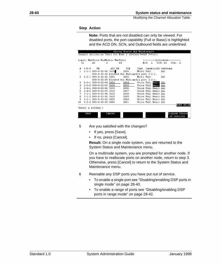
28-60 System status and maintenanceModifying the Channel Allocation Table
Note: Ports that are not disabled can only be viewed. For disabled ports, the port capability (Full or Basic) is highlighted and the ACD DN, SCN, and Outbound fields are underlined.
5 Are you satisfied with the changes?
• If yes, press [Save].
• If no, press [Cancel].
Result: On a single node system, you are returned to the System Status and Maintenance menu.
On a multinode system, you are prompted for another node. If you have to reallocate ports on another node, return to step 3. Otherwise, press [Cancel] to return to the System Status and Maintenance menu.
6 Reenable any DSP ports you have put out of service.
• To enable a single port see “Disabling/enabling DSP ports in single mode” on page 28-40.
• To enable a range of ports see “Disabling/enabling DSP ports in range mode” on page 28-42.
Step Action
Standard 1.0 System Administration Guide January 1998
Chapter 28
System status and maintenance 28-61Section E: Disk Maintenance
In this section
Overview 28-62
Checking disk status 28-63
Disabling disk shadowing (unsynching) 28-68
Replacing a failed disk 28-69
Reenabling disk shadowing (synching a disk pair) 28-70
Running diagnostics on a disk or a disk pair 28-72
Standard 1.0 System Administration Guide January 1998
28-62 System status and maintenance
is a ir
se on
cs]
r, ch ey
Overview
Overview
Introduction The Disk Maintenance screen allows you to view the operational state of the disks on your system. If your system shadowed system, you can also synch or unsynch a disk pausing the functions available through this screen.
When to use this feature
Shadowed or Unshadowed systemIf you suspect that your disks are not functioning properly, uthe Disk Maintenance screen to check the status of the disksyour system. See “Checking disk status” on page 28-63.
If you suspect a particular disk or disk pair is not functioningproperly, you can run a diagnostic check using the [Diagnostisoftkey on the Disk Maintenance screen. See “Running diagnostics on a disk or a disk pair” on page 28-72.
Shadowed systemIf you need to replace or repair one of the disks in a disk paiyou must first disable disk shadowing for the disk pair (unsynthe disk pair). The Disk Maintenance screen provides a softkfor unsynching a disk pair. See “Disabling disk shadowing (unsynching)” on page 28-68.
After a disk has been replaced or repaired, you need to synchronize the disk pair. The Disk Maintenance screen provides a softkey for synching a disk pair. See “Reenablingdisk shadowing (synching a disk pair)” on page 28-70.
Standard 1.0 System Administration Guide January 1998
System status and maintenance 28-63Checking disk status
and
re
Checking disk status
Introduction The Disk Maintenance screen lists the disks on your system displays their current states.
Disk status A disk can be in one of the following states:
• ReadWrite The disk is in service (functioning properly according to Meridian Mail).
• NoAccess The disk is disabled. Check your SEERs for moinformation.
• Faulty The disk has failed a diagnostics check that was performed using the [Diagnostics] softkey from the Disk Maintenance screen.
Shadowed systems only
• Write The disk is being written to. A disk may have this status during a disk synchronization.
Procedure To check disk status, use the following steps.
Starting Point: The Main Menu
Step Action
1 Select System Status and Maintenance.
Result: The System Status and Maintenance menu is displayed.
2 Select Disk Maintenance.
Result: The Disk Maintenance screen is displayed.
Standard 1.0 System Administration Guide January 1998
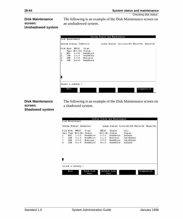
28-64 System status and maintenance
on
on
Checking disk status
Disk Maintenance screen:Unshadowed system
The following is an example of the Disk Maintenance screenan unshadowed system.
Disk Maintenance screen:Shadowed system
The following is an example of the Disk Maintenance screena shadowed system.
Standard 1.0 System Administration Guide January 1998
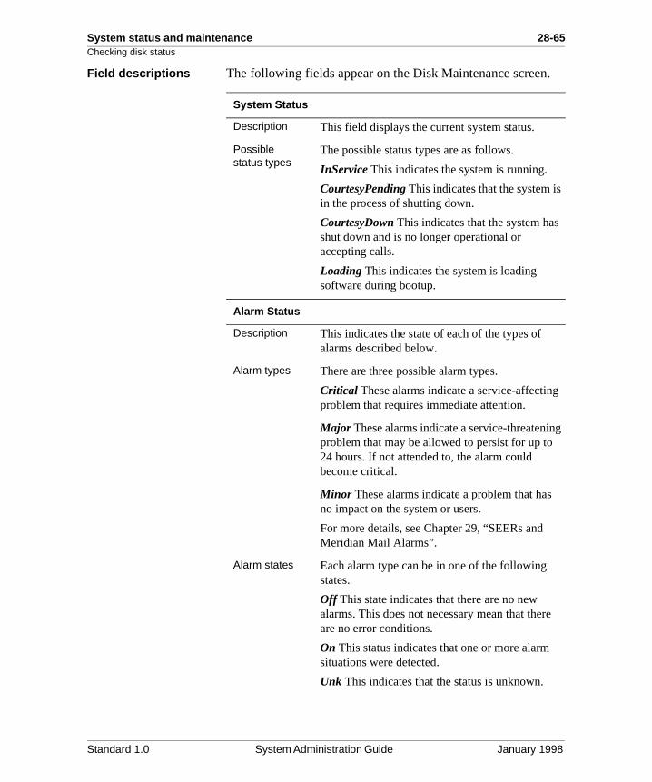
System status and maintenance 28-65Checking disk status
.
g
Field descriptions The following fields appear on the Disk Maintenance screen
System Status
Description This field displays the current system status.
Possible status types
The possible status types are as follows.
InService This indicates the system is running.
CourtesyPending This indicates that the system isin the process of shutting down.
CourtesyDown This indicates that the system hasshut down and is no longer operational or accepting calls.
Loading This indicates the system is loading software during bootup.
Alarm Status
Description This indicates the state of each of the types of alarms described below.
Alarm types There are three possible alarm types.
Critical These alarms indicate a service-affectingproblem that requires immediate attention.
Major These alarms indicate a service-threateninproblem that may be allowed to persist for up to 24 hours. If not attended to, the alarm could become critical.
Minor These alarms indicate a problem that hasno impact on the system or users.
For more details, see Chapter 29, “SEERs and Meridian Mail Alarms”.
Alarm states Each alarm type can be in one of the following states.
Off This state indicates that there are no new alarms. This does not necessary mean that thereare no error conditions.
On This status indicates that one or more alarm situations were detected.
Unk This indicates that the status is unknown.
Standard 1.0 System Administration Guide January 1998
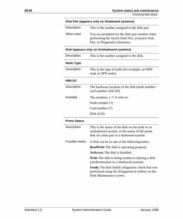
28-66 System status and maintenance
s
Checking disk status
Disk Pair (appears only on Shadowed systems)
Description This is the number assigned to the disk pair.
When used You are prompted for the disk pair number whenperforming the Synch Disk Pair, Unsynch Disk Pair, or Diagnostics functions.
Disk (appears only on Unshadowed systems)
Description This is the number assigned to the disk.
Node Type
Description This is the type of node (for example, an MSP node or SPN node).
HWLOC
Description The hardware location of the disk (node number–card number–disk ID).
Example The numbers 1–7–0 refer to:
Node number (1)
Card number (7)
Disk id (0)
Prime Status
Description This is the status of the disk on the node in an unshadowed system, or the status of the prime disk of a disk pair in a shadowed system.
Possible states A disk can be in one of the following states:
ReadWrite The disk is operating properly.
NoAccess The disk is disabled.
Write The disk is being written to (during a disk synchronization in a shadowed system).
Faulty The disk failed a diagnostic check that waperformed using the [Diagnostics] softkey on theDisk Maintenance screen.
Standard 1.0 System Administration Guide January 1998
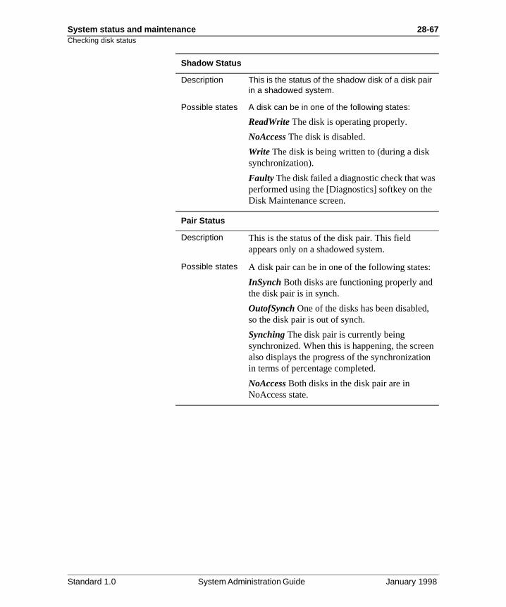
System status and maintenance 28-67Checking disk status
s
n
Shadow Status
Description This is the status of the shadow disk of a disk pair in a shadowed system.
Possible states A disk can be in one of the following states:
ReadWrite The disk is operating properly.
NoAccess The disk is disabled.
Write The disk is being written to (during a disk synchronization).
Faulty The disk failed a diagnostic check that waperformed using the [Diagnostics] softkey on theDisk Maintenance screen.
Pair Status
Description This is the status of the disk pair. This field appears only on a shadowed system.
Possible states A disk pair can be in one of the following states:
InSynch Both disks are functioning properly and the disk pair is in synch.
OutofSynch One of the disks has been disabled, so the disk pair is out of synch.
Synching The disk pair is currently being synchronized. When this is happening, the screealso displays the progress of the synchronizationin terms of percentage completed.
NoAccess Both disks in the disk pair are in NoAccess state.
Standard 1.0 System Administration Guide January 1998
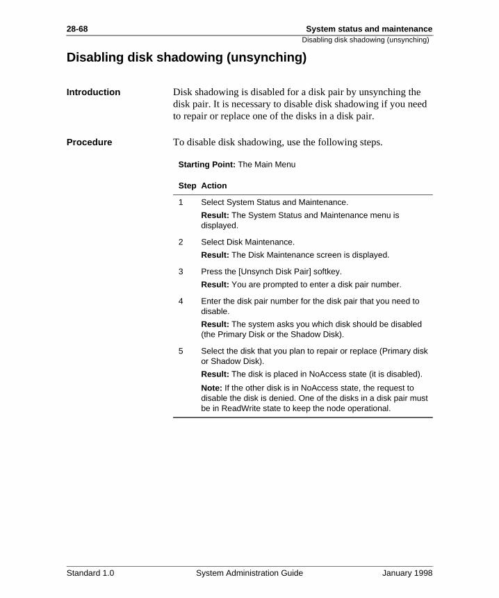
28-68 System status and maintenanceDisabling disk shadowing (unsynching)
ed
Disabling disk shadowing (unsynching)
Introduction Disk shadowing is disabled for a disk pair by unsynching thedisk pair. It is necessary to disable disk shadowing if you neto repair or replace one of the disks in a disk pair.
Procedure To disable disk shadowing, use the following steps.
Starting Point: The Main Menu
Step Action
1 Select System Status and Maintenance.
Result: The System Status and Maintenance menu is displayed.
2 Select Disk Maintenance.
Result: The Disk Maintenance screen is displayed.
3 Press the [Unsynch Disk Pair] softkey.
Result: You are prompted to enter a disk pair number.
4 Enter the disk pair number for the disk pair that you need to disable.
Result: The system asks you which disk should be disabled (the Primary Disk or the Shadow Disk).
5 Select the disk that you plan to repair or replace (Primary disk or Shadow Disk).
Result: The disk is placed in NoAccess state (it is disabled).
Note: If the other disk is in NoAccess state, the request to disable the disk is denied. One of the disks in a disk pair must be in ReadWrite state to keep the node operational.
Standard 1.0 System Administration Guide January 1998
System status and maintenance 28-69Replacing a failed disk
Replacing a failed disk
Where to find information
The procedures for replacing a failed disk are provided in theInstallation and Maintenance Guide (NTP 555-70x1-250).
Standard 1.0 System Administration Guide January 1998
28-70 System status and maintenanceReenabling disk shadowing (synching a disk pair)
isk air.
has
te”
Reenabling disk shadowing (synching a disk pair)
Introduction After a disk has been replaced or repaired, you need to synchronize the disk pair to reenable disk shadowing. The DMaintenance screen provides a softkey for synching a disk p
Tip If you need to synch more than one disk pair, you can beginsynching subsequent disk pairs as soon as the first disk pairstarted synching. You do not have to wait for one disk pair tofinish synching before synching another disk pair.
Timing This procedure takes at least thirty minutes. The actual timedepends on the size of the source disk.
Procedure To re-enable disk shadowing, use the following steps.
Starting Point: The Main Menu
What happens during synchronization
The screen displays the progress of the synchronization. It displays the percentage of synchronization that is complete.
The status of the disk that is being written to changes to “Wriuntil the synching is complete. When complete, the status ofboth disks is set to ReadWrite if both disks are functioning properly. If one of the disks in the disk pair is faulty, the synching will fail and you are notified by a screen message.
Step Action
1 Select System Status and Maintenance.
Result: The System Status and Maintenance menu is displayed.
2 Select Disk Maintenance.
Result: The Disk Maintenance screen is displayed.
3 Press the [Synch Disk Pair] softkey.
Result: You are prompted to enter a disk pair number.
4 Enter the number of the disk pair that you need to synch (to re-enable disk shadowing for the disk pair) and press <Return>.
Result: The synching begins.
Standard 1.0 System Administration Guide January 1998
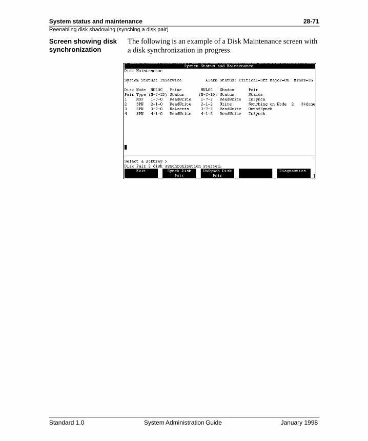
System status and maintenance 28-71Reenabling disk shadowing (synching a disk pair)
ith
Screen showing disk synchronizationThe following is an example of a Disk Maintenance screen wa disk synchronization in progress.
Standard 1.0 System Administration Guide January 1998
28-72 System status and maintenanceRunning diagnostics on a disk or a disk pair
on if
Running diagnostics on a disk or a disk pair
Introduction If you suspect a problem with a disk, run the diagnostic function the disk. The system responds with a message indicatingthe disk is ok (passed) or faulty (failed).
Procedure To run the diagnostic function on a disk or disk pair, use thefollowing steps.
Starting Point: The Main Menu
Step Action
1 Select System Status and Maintenance.
Result: The System Status and Maintenance menu is displayed.
2 Select Disk Maintenance.
Result: The Disk Maintenance screen is displayed.
3 Press the [Diagnostics] softkey.
Result: You are prompted to enter a disk number (or a disk pair number on a shadowed system).
4 Enter the number of the disk or disk pair you want to check.
Result (on a shadowed system): The system asks you which disk you want to check (the Primary Disk or the Shadow Disk). Select one of the disks. After a few moments, the system responds with the results of the diagnostic check.
Result (on an unshadowed system): After a few moments, the system responds with the results of the diagnostic check.
Standard 1.0 System Administration Guide January 1998
System status and maintenance 28-73Running diagnostics on a disk or a disk pair
.
.
Possible results The system will respond with one of the following messages
Message Meaning
Disk diagnostics passed. The disk is functioning normally
Disk diagnostics failed. xxxx
(where “xxxx” is the error code)
The disk is not functioning properly. A SEER is generated which will provide more details on what the problem is and what action you should take.
Invalid component state to do disk diagnostics.
If the disk is not in a valid state (InService, OutOfService, Faulty, or Unconfigured), then the diagnostics routine will not run. Contact your regional support centre.
Cannot perform diagnostics. Disk Synchronization in progress.
The disk pair you have selected iscurrently being synched. You must wait for the synching to complete before you can run diagnostics on one of the disks in the disk pair.
Invalid node state to run diagnostics on this disk.
The node must be InService, OutOfService, or in Standby statefor the diagnostics routine to run.
Standard 1.0 System Administration Guide January 1998

28-74 System status and maintenanceRunning diagnostics on a disk or a disk pair
Standard 1.0 System Administration Guide January 1998
System status and maintenance 28-75
Section F: Diagnostic Schedules
In this section
Overview 28-76
What are Voice Path Diagnostics? 28-77
Changing the parameters and schedule for diagnostics 28-78
Analyzing the results of the diagnostics 28-82
Standard 1.0 System Administration Guide January 1998
28-76 System status and maintenanceOverview
can
.
ld
,
sy
dle
Overview
Introduction The Diagnostics Schedules screen allows you to schedule adiagnostic check on the voice channels in your system. You control what time the diagnostics take place (to avoid peak traffic periods), and whether a faulty channel is taken off-line
When to use this feature
If you have not enabled voice path diagnostics yet, you wouuse this feature to
• schedule when you want voice path diagnostics to take place
If the voice path diagnostic tests are causing a traffic problemyou can use this feature to
• change the voice path diagnostics schedule to a less-butime
• disable voice path diagnostic testing
• change what happens when voice path diagnostics fail (whether channels taken offline or left InService)
• change the duration of the voice path diagnostics
• change the minimum number of channels that must be ibefore voice path diagnostics will run
Standard 1.0 System Administration Guide January 1998
System status and maintenance 28-77What are Voice Path Diagnostics?
l
ake .
n e
s, .
What are Voice Path Diagnostics?
Definition: Voice Path Diagnostics
Voice Path Diagnostics is a feature that tests the operationastate of the voice channels.
How the test is done The system sets up calls which go from Meridian Mail to theswitch and back. Two channels are tested at a time (one to mthe call to the switch, one to receive the call from the switch)Only InService channels are tested.
The test continues until either
• all InService channels are tested or
• the maximum duration allowed for the tests runs out
Definition: Originator and Destination
The Originator is the port used to make the call from MeridiaMail to the switch. The Destination is the port used to receivthe call back from the switch to Meridian Mail.
Possible test results A channel can pass, fail, or be left untested. For more detailsee “Analyzing the results of the diagnostics” on page 28-82
Standard 1.0 System Administration Guide January 1998
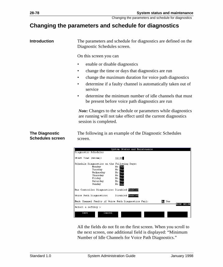
28-78 System status and maintenanceChanging the parameters and schedule for diagnostics
the
f
st
tics
Changing the parameters and schedule for diagnostics
Introduction The parameters and schedule for diagnostics are defined onDiagnostic Schedules screen.
On this screen you can
• enable or disable diagnostics
• change the time or days that diagnostics are run
• change the maximum duration for voice path diagnostics
• determine if a faulty channel is automatically taken out oservice
• determine the minimum number of idle channels that mube present before voice path diagnostics are run
Note: Changes to the schedule or parameters while diagnosare running will not take effect until the current diagnostics session is completed.
The Diagnostic Schedules screen
The following is an example of the Diagnostic Schedules screen.
All the fields do not fit on the first screen. When you scroll tothe next screen, one additional field is displayed: “Minimum Number of Idle Channels for Voice Path Diagnostics.”
Standard 1.0 System Administration Guide January 1998
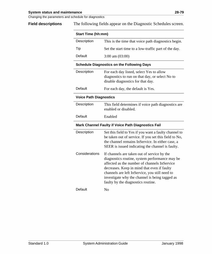
System status and maintenance 28-79Changing the parameters and schedule for diagnostics
en.
.
e
,
Field descriptions The following fields appear on the Diagnostic Schedules scre
Start Time (hh:mm)
Description This is the time that voice path diagnostics begin
Tip Set the start time to a low-traffic part of the day.
Default 3:00 am (03:00)
Schedule Diagnostics on the Following Days
Description For each day listed, select Yes to allow diagnostics to run on that day, or select No to disable diagnostics for that day.
Default For each day, the default is Yes.
Voice Path Diagnostics
Description This field determines if voice path diagnostics arenabled or disabled.
Default Enabled
Mark Channel Faulty if Voice Path Diagnostics Fail
Description Set this field to Yes if you want a faulty channel tobe taken out of service. If you set this field to Nothe channel remains InService. In either case, a SEER is issued indicating the channel is faulty.
Considerations If channels are taken out of service by the diagnostics routine, system performance may beaffected as the number of channels InService decreases. Keep in mind that even if faulty channels are left InService, you still need to investigate why the channel is being tagged as faulty by the diagnostics routine.
Default No
Standard 1.0 System Administration Guide January 1998
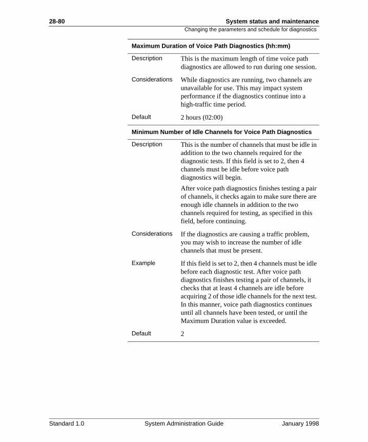
28-80 System status and maintenanceChanging the parameters and schedule for diagnostics
n.
in
ir re
e
t.
Maximum Duration of Voice Path Diagnostics (hh:mm)
Description This is the maximum length of time voice path diagnostics are allowed to run during one sessio
Considerations While diagnostics are running, two channels areunavailable for use. This may impact system performance if the diagnostics continue into a high-traffic time period.
Default 2 hours (02:00)
Minimum Number of Idle Channels for Voice Path Diagnostics
Description This is the number of channels that must be idle addition to the two channels required for the diagnostic tests. If this field is set to 2, then 4 channels must be idle before voice path diagnostics will begin.
After voice path diagnostics finishes testing a paof channels, it checks again to make sure there aenough idle channels in addition to the two channels required for testing, as specified in thisfield, before continuing.
Considerations If the diagnostics are causing a traffic problem, you may wish to increase the number of idle channels that must be present.
Example If this field is set to 2, then 4 channels must be idlbefore each diagnostic test. After voice path diagnostics finishes testing a pair of channels, it checks that at least 4 channels are idle before acquiring 2 of those idle channels for the next tesIn this manner, voice path diagnostics continuesuntil all channels have been tested, or until the Maximum Duration value is exceeded.
Default 2
Standard 1.0 System Administration Guide January 1998
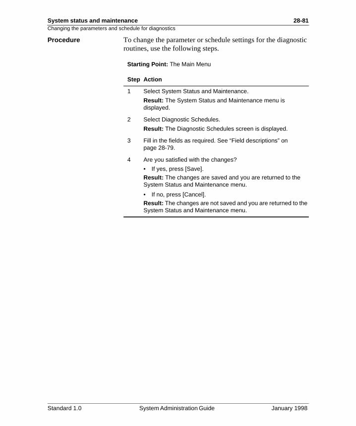
System status and maintenance 28-81Changing the parameters and schedule for diagnostics
stic
Procedure To change the parameter or schedule settings for the diagnoroutines, use the following steps.Starting Point: The Main Menu
Step Action
1 Select System Status and Maintenance.
Result: The System Status and Maintenance menu is displayed.
2 Select Diagnostic Schedules.
Result: The Diagnostic Schedules screen is displayed.
3 Fill in the fields as required. See “Field descriptions” on page 28-79.
4 Are you satisfied with the changes?
• If yes, press [Save].
Result: The changes are saved and you are returned to the System Status and Maintenance menu.
• If no, press [Cancel].
Result: The changes are not saved and you are returned to the System Status and Maintenance menu.
Standard 1.0 System Administration Guide January 1998
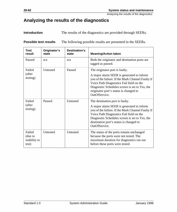
28-82 System status and maintenanceAnalyzing the results of the diagnostics
Analyzing the results of the diagnostics
Introduction The results of the diagnostics are provided through SEERs.
Possible test results The following possible results are presented in the SEERs.
Test result
Originator’s state
Destination’s state Meaning/Action taken
Passed n/a n/a Both the originator and destination ports aretagged as passed.
Failed (after testing)
Untested Passed The originator port is faulty.
A major alarm SEER is generated to inform you of the failure. If the Mark Channel Faulty if Voice Path Diagnostics Fail field on the Diagnostic Schedules screen is set to Yes, theoriginator port’s status is changed to OutOfService.
Failed (after testing)
Passed Untested The destination port is faulty.
A major alarm SEER is generated to inform you of the failure. If the Mark Channel Faulty if Voice Path Diagnostics Fail field on the Diagnostic Schedules screen is set to Yes, thedestination port’s status is changed to OutOfService.
Failed (due to inability to test)
Untested Untested The status of the ports remain unchanged because the ports were not tested. The maximum duration for diagnostics ran out before these ports were tested.
Standard 1.0 System Administration Guide January 1998
System status and maintenance 28-83Analyzing the results of the diagnostics
nels
e
tem
r
th er
) h ult
Summary SEER (number 7400)
When a diagnostics session is completed (all InService chanare tested, or the maximum duration allowed expires), a summary SEER is generated.
The SEER number is 7400, with severity level “Info,” and typ“Admin.”
This SEER provides the following information:
• the total number of InService channels found on the sys
• the total number of channels tested
• the total number of channels failed
• the total number of channels untested
• a list of failed channels
Other SEERs (class 74)
Scan the SEERs generated during the diagnostic session foclass 74 SEERs. Class 74 SEERs include SEERs related tofailed or untested channels.
Impact on Operational Measurement reports
On the Services Summary report, the count for the Voice PaDiagnostics service will be greater than or equal to the numbof channels tested.
The count for the default voice service (usually Voice Menuswill also show some additional calls in the time period in whicvoice path diagnostics was running. This is because the defavoice service is used to assist in establishing the call loop between Meridian Mail and the switch.
Standard 1.0 System Administration Guide January 1998

28-84 System status and maintenanceAnalyzing the results of the diagnostics
Standard 1.0 System Administration Guide January 1998
Chapter 29
SEERs and Meridian Mail Alarms
In this chapter
Overview 29-2
Section A: SEERs and Alarms 29-3
Section B: Customizing SEER processing 29-15
Section C: Notification options for SEERs and alarms 29-27
29-2 SEERs and Meridian Mail Alarms Overview
on d
on
es
Overview
Introduction This chapter describes System Event and Error Reports (SEERs) and Meridian Mail alarms in the following sections.
Section A: SEERs and Alarms provides conceptual informatiabout SEERs and Alarms. Procedures for SEER retrieval analarm silencing are described in this section.
Section B: Customizing SEER processing provides informatiregarding SEER remapping, SEER throttling, and SEER escalation.
Section C: Notification options for SEERs and alarms describthe SEER and alarm processing path in the Meridian Mail system. Also, the procedures for setting up SEERs printing, filtering, and triggering are described.
Standard 1.0 System Administration Guide January 1998
SEERs and Meridian Mail Alarms 29-3
Section A: SEERs and Alarms
In this section
What is a SEER? 29-4
Retrieving SEERs 29-6
What is an alarm? 29-9
How to check alarm status 29-10
Silencing an alarm 29-12
Standard 1.0 System Administration Guide January 1998
29-4 SEERs and Meridian Mail Alarms What is a SEER?
ted
ate
nd
of ents of ing
:
What is a SEER?
Concept System Event and Error Reports (SEERs), which are generaby the Meridian Mail system software components, identify every significant system event and error that occurs.
An event is a minor glitch or an announcement of normal system activities (for example, the start of an automatic tapebackup). Events documented in a SEER do not usually indica problem with the Meridian Mail functionality.
An error is a hardware or software fault that may prevent Meridian Mail from functioning properly (for example, a hardware component that failed diagnostics, or a failure to fia system file). An error creates one or more SEERs.
You must be able to read, interpret, and assess the severityevents and errors to determine if they are regular system ev(such as a system audit) or system errors. An understandingSEERs is also essential for diagnosing problems. Before askfor help in dealing with a major system problem, the system administrator must be ready to provide a collection of SEERreports from which the Northern Telecom support staff can determine the history of the problem. From these reports, maintenance personnel will be able to diagnose the problemeffectively.
SEER components Each SEER is identified by a number consisting of two parts
• SEER class, which classifies a particular software component
• SEER number, which identifies a particular report for a class
ExampleSEER 6603 is SEER number 03 from class 66.
Standard 1.0 System Administration Guide January 1998
SEERs and Meridian Mail Alarms 29-5What is a SEER?
ay
y
s, the that
o
isk
up
Note: Due to ongoing improvements in the software, there mbe instances where the information on the SEER itself is different from the information presented in the Maintenance Messages (SEERs) Reference Manual (NTP 555-7001-510). Should this occur, the information in the SEER printed out byour system should take precedence.
How SEERs are accessed
SEERs can be displayed on a terminal or printed out on a printer. The reports provide information about the SEER clasSEER number, the severity level of errors, the date and timeSEER was generated, and a description of the event or erroroccurred at that time. This information is used primarily by system administrators and maintenance personnel to confirmthat a system is running correctly, to isolate a system fault, tdiagnose a hardware or software problem, or to solve a problem.
SEERs are printed and stored in the SEER file on the systemdisk at the time of the error or event. The SEERs stored on dcan be viewed or printed at a later time. The SEER file holdsto 4000 records.
Standard 1.0 System Administration Guide January 1998
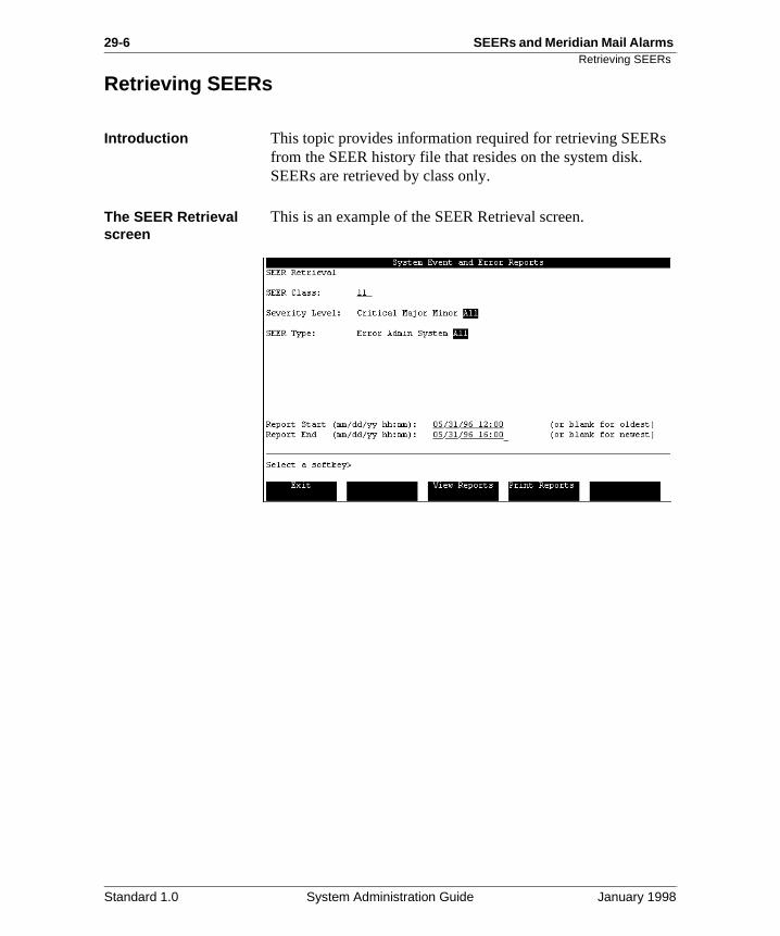
29-6 SEERs and Meridian Mail Alarms Retrieving SEERs
Retrieving SEERs
Introduction This topic provides information required for retrieving SEERsfrom the SEER history file that resides on the system disk. SEERs are retrieved by class only.
The SEER Retrieval screen
This is an example of the SEER Retrieval screen.
Standard 1.0 System Administration Guide January 1998
SEERs and Meridian Mail Alarms 29-7Retrieving SEERs
.
e
al.
Field descriptions This table describes the fields in the SEER Retrieval screen
SEER Class
Description The class of SEERs that you want to retrieve. If you leave the field blank, all classes will be retrieved.
Classes For a list of supported SEERs classes, refer to thMaintenance Messages (SEERs) Reference Manual (NTP 555-7001-510).
Default The field is blank.
Severity Level
Description The severity level of the SEERs class.
Options Critical, Major, Minor, All
Default All
SEER Type
Description The SEER type required.
Options Error, Admin, System, All
Default All
Report Start/End
Description This field allows the administrator to specify the start and end date and time for the SEER retrievIf left blank, the search provides all SEERs meeting the search criteria that are in the historyfile.
Default The field is blank.
Standard 1.0 System Administration Guide January 1998
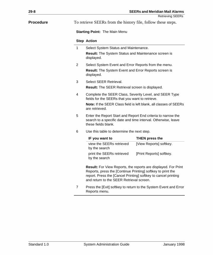
29-8 SEERs and Meridian Mail Alarms Retrieving SEERs
Procedure To retrieve SEERs from the history file, follow these steps.
Starting Point: The Main Menu
Step Action
1 Select System Status and Maintenance.
Result: The System Status and Maintenance screen is displayed.
2 Select System Event and Error Reports from the menu.
Result: The System Event and Error Reports screen is displayed.
3 Select SEER Retrieval.
Result: The SEER Retrieval screen is displayed.
4 Complete the SEER Class, Severity Level, and SEER Type fields for the SEERs that you want to retrieve.
Note: If the SEER Class field is left blank, all classes of SEERs are retrieved.
5 Enter the Report Start and Report End criteria to narrow the search to a specific date and time interval. Otherwise, leave these fields blank.
6 Use this table to determine the next step.
Result: For View Reports, the reports are displayed. For Print Reports, press the [Continue Printing] softkey to print the report. Press the [Cancel Printing] softkey to cancel printing and return to the SEER Retrieval screen.
7 Press the [Exit] softkey to return to the System Event and Error Reports menu.
IF you want to THEN press the
view the SEERs retrieved by the search
[View Reports] softkey.
print the SEERs retrieved by the search
[Print Reports] softkey.
Standard 1.0 System Administration Guide January 1998
SEERs and Meridian Mail Alarms 29-9What is an alarm?
t
res
at d
the
What is an alarm?
Introduction An alarm is an audible notification that something is not righwith the Meridian Mail system. Alarms are sounded if a corresponding severity level SEER is issued to indicate a system problem.
Alarm types There are three types of alarms: critical, major, and minor.
Critical alarmThese alarms indicate a service-affecting problem that requiimmediate attention.
Major alarmThis type of alarm indicates a service-threatening problem thmay be allowed to persist (for up to 24 hours). If not attendeto, the alarm could become critical.
Minor alarmThis type of alarm indicates a problem that has no impact onsystem or users.
Standard 1.0 System Administration Guide January 1998
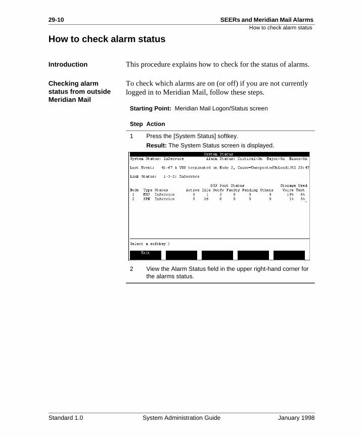
29-10 SEERs and Meridian Mail Alarms How to check alarm status
s.
How to check alarm status
Introduction This procedure explains how to check for the status of alarm
Checking alarm status from outside Meridian Mail
To check which alarms are on (or off) if you are not currentlylogged in to Meridian Mail, follow these steps.
Starting Point: Meridian Mail Logon/Status screen
Step Action
1 Press the [System Status] softkey.
Result: The System Status screen is displayed.
2 View the Alarm Status field in the upper right-hand corner for the alarms status.
Standard 1.0 System Administration Guide January 1998
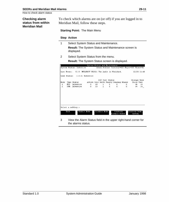
SEERs and Meridian Mail Alarms 29-11How to check alarm status
Checking alarm status from within Meridian Mail
To check which alarms are on (or off) if you are logged in to Meridian Mail, follow these steps.
Starting Point: The Main Menu
Step Action
1 Select System Status and Maintenance.
Result: The System Status and Maintenance screen is displayed.
2 Select System Status from the menu.
Result: The System Status screen is displayed.
3 View the Alarm Status field in the upper right-hand corner for the alarms status.
Standard 1.0 System Administration Guide January 1998
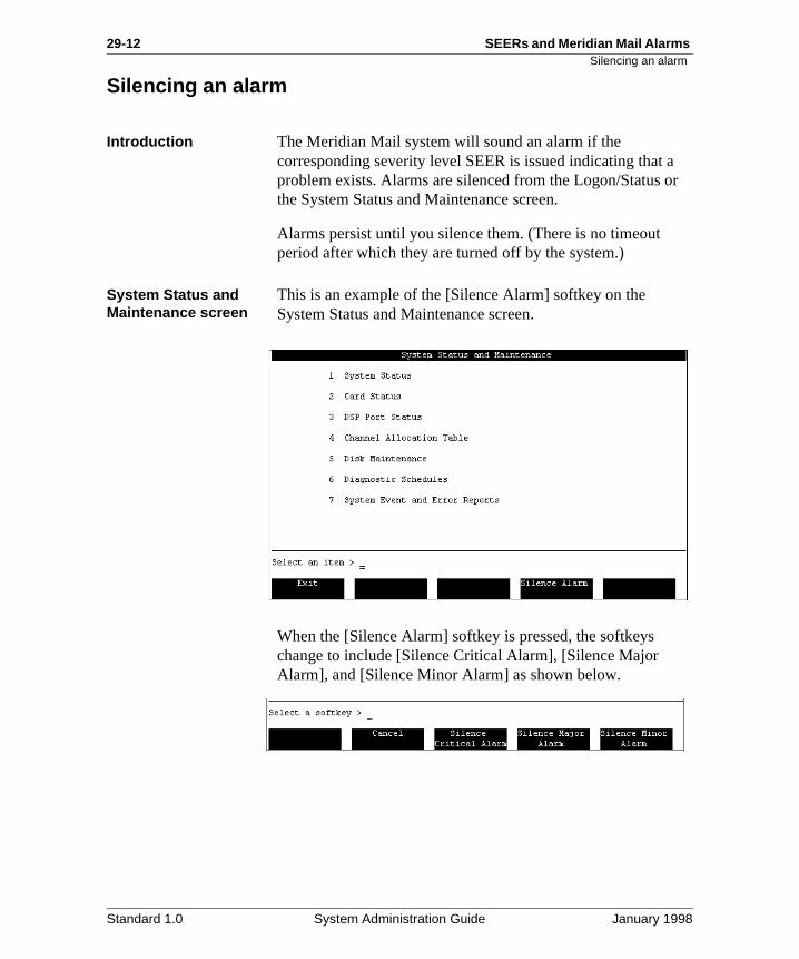
29-12 SEERs and Meridian Mail Alarms Silencing an alarm
r
Silencing an alarm
Introduction The Meridian Mail system will sound an alarm if the corresponding severity level SEER is issued indicating that aproblem exists. Alarms are silenced from the Logon/Status othe System Status and Maintenance screen.
Alarms persist until you silence them. (There is no timeout period after which they are turned off by the system.)
System Status and Maintenance screen
This is an example of the [Silence Alarm] softkey on the System Status and Maintenance screen.
When the [Silence Alarm] softkey is pressed, the softkeys change to include [Silence Critical Alarm], [Silence Major Alarm], and [Silence Minor Alarm] as shown below.
Standard 1.0 System Administration Guide January 1998
SEERs and Meridian Mail Alarms 29-13Silencing an alarm
Silencing an alarm when logged in to Meridian Mail
To silence an alarm when logged in to Meridian Mail, follow these steps.
Starting Point: The Main Menu
Silencing an alarm from the Logon/Status screen
To silence an alarm from the Meridian Mail Logon/Status screen, follow these steps.
Starting Point: The Meridian Mail Logon/Status screen
Step Action
1 Select System Status and Maintenance.
Result: The System Status and Maintenance screen is displayed.
2 Press the [Silence Alarms] softkey.
Result: The [Silence Critical], [Silence Major], and [Silence Minor Alarm] softkeys are displayed.
3 Press the appropriate softkey to cancel the type of alarm that is sounding.
Result: The alarm is silenced.
Press [Cancel] to return to the System Status and Maintenance screen.
Step Action
1 Press the [Silence Alarms] softkey.
Result: The [Silence Critical], [Silence Major], and [Silence Minor Alarm] softkeys are displayed.
2 Press the appropriate softkey to cancel the type of alarm that is sounding.
Result: The alarm is silenced.
Press [Cancel] to return to the Meridian Mail Logon/Status screen.
Standard 1.0 System Administration Guide January 1998

29-14 SEERs and Meridian Mail Alarms Silencing an alarm
Standard 1.0 System Administration Guide January 1998
SEERs and Meridian Mail Alarms 29-15
Section B: Customizing SEER processing
In this section
Overview 29-16
Using SEER remapping 29-17
Using SEER throttling 29-20
Using SEER escalation 29-23
Standard 1.0 System Administration Guide January 1998
29-16 SEERs and Meridian Mail Alarms Overview
for
Overview
Introduction This section includes descriptions of three SEERs features: remapping, throttling, and escalation, as well as procedures setting up these features on the Meridian Mail system.
Standard 1.0 System Administration Guide January 1998
SEERs and Meridian Mail Alarms 29-17Using SEER remapping
or
d s do
ng. L
ng o R
Using SEER remapping
Description SEERs remapping allows the system administrator to remapreassign the severity level of up to 60 SEERs to a higher or lower severity level. The remapping can be applied to individual SEERs only, and the revised configuration is storein the System Profile on disk. This means that the parameternot have to be reentered after a system reboot.
Note: SEER remapping is not the same as memory remappiMemory remapping is done using the special utility, SE_UTIfunction, with the aid of your distributor. For information on memory remapping, refer to the Maintenance Messages (SEERs) Reference Manual (NTP 555-7001-510).
The SEER remapping changes are made using the SEER Remap Table. Changes are effective immediately upon savithe table. No validation is performed on the revised SEERs tdetermine if the entered SEER actually exists, if the severitylevel is different from the existing severity level, or if the SEEhas already been remapped using memory remapping.
If the altered severity level is no longer required, delete the entry from the SEER Remap Table instead of resetting the severity level back to the original.
Standard 1.0 System Administration Guide January 1998
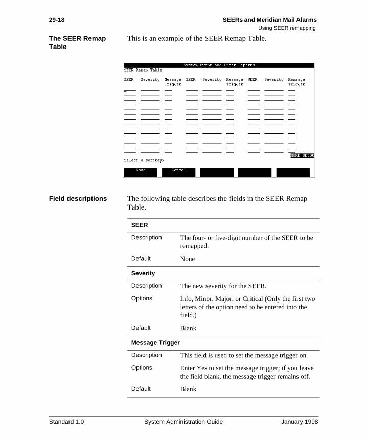
29-18 SEERs and Meridian Mail Alarms Using SEER remapping
e
The SEER Remap Table
This is an example of the SEER Remap Table.
Field descriptions The following table describes the fields in the SEER RemapTable.
SEER
Description The four- or five-digit number of the SEER to be remapped.
Default None
Severity
Description The new severity for the SEER.
Options Info, Minor, Major, or Critical (Only the first two letters of the option need to be entered into the field.)
Default Blank
Message Trigger
Description This field is used to set the message trigger on.
Options Enter Yes to set the message trigger; if you leavthe field blank, the message trigger remains off.
Default Blank
Standard 1.0 System Administration Guide January 1998
SEERs and Meridian Mail Alarms 29-19Using SEER remapping
Procedure To remap SEERs, follow these steps.
Starting Point: The Main Menu
Step Action
1 Select System Status and Maintenance.
Result: The System Status and Maintenance menu is displayed.
2 Select System Event and Error Reports.
Result: The System Event and Error Reports menu is displayed.
3 Select SEER Remap Table.
Result: The SEER Remap Table is displayed.
4 Enter the SEER number in the SEER field.
5 Use the tab key to move the cursor to the Severity field. Enter the new severity.
6 Use the tab key to move the cursor to the Message Trigger field. To set the message trigger, enter Yes in this field.
7 Use this table to determine the next step.
8 Press the [Save] softkey to save the remapping table.
Result: The table is saved and the SEERs are remapped.
Press the [Cancel] softkey to cancel changes to the remap table.
Result: The changes are cancelled and you are returned to the System Event and Error Reports menu.
IF THEN
you have more SEERs to remap
repeat steps 4 through 6.
you have entered all SEERs in the table that require remapping
go to step 8.
Standard 1.0 System Administration Guide January 1998
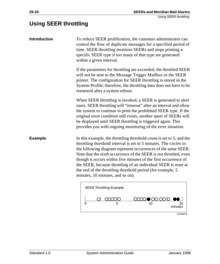
29-20 SEERs and Meridian Mail Alarms Using SEER throttling
n of
ER
be
ert
he ill
the ER. en
at
Using SEER throttling
Introduction To reduce SEER proliferation, the customer administrator cacontrol the flow of duplicate messages for a specified periodtime. SEER throttling monitors SEERs and stops printing a specific SEER type if too many of that type are generated within a given interval.
If the parameters for throttling are exceeded, the throttled SEwill not be sent to the Message Trigger Mailbox or the SEERprinter. The configuration for SEER throttling is stored in theSystem Profile; therefore, the throttling data does not have toreentered after a system reboot.
When SEER throttling is invoked, a SEER is generated to alusers. SEER throttling will “timeout” after an interval and allowthe system to continue to print the prohibited SEER type. If toriginal error condition still exists, another spurt of SEERs wbe displayed until SEER throttling is triggered again. This provides you with ongoing monitoring of the error situation.
Example In this example, the throttling threshold count is set to 5, and throttling threshold interval is set to 5 minutes. The circles inthe following diagram represent occurrences of the same SENote that the sixth occurrence of the SEER is not throttled, evthough it occurs within five minutes of the first occurrence ofthe SEER, because throttling of an individual SEER is reset the end of the throttling threshold period (for example, 5 minutes, 10 minutes, and so on).
SEER Throttling Example
0 5 10 15minutes
G100412
Standard 1.0 System Administration Guide January 1998
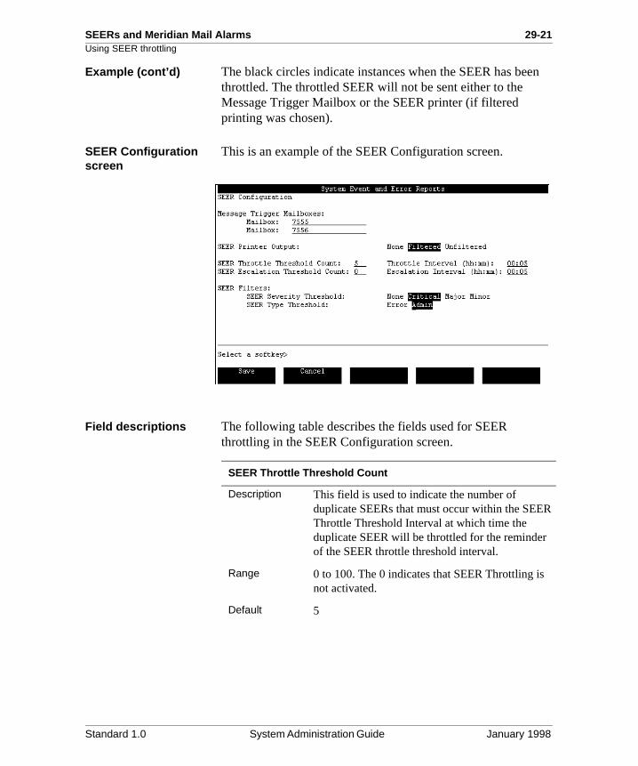
SEERs and Meridian Mail Alarms 29-21Using SEER throttling
n
R
Example (cont’d) The black circles indicate instances when the SEER has beethrottled. The throttled SEER will not be sent either to the Message Trigger Mailbox or the SEER printer (if filtered printing was chosen).
SEER Configuration screen
This is an example of the SEER Configuration screen.
Field descriptions The following table describes the fields used for SEER throttling in the SEER Configuration screen.
SEER Throttle Threshold Count
Description This field is used to indicate the number of duplicate SEERs that must occur within the SEEThrottle Threshold Interval at which time the duplicate SEER will be throttled for the reminderof the SEER throttle threshold interval.
Range 0 to 100. The 0 indicates that SEER Throttling isnot activated.
Default 5
Standard 1.0 System Administration Guide January 1998
29-22 SEERs and Meridian Mail Alarms Using SEER throttling
f e
Setting SEER throttling
To set throttling for SEERs, follow these steps.
Starting Point: The Main Menu
SEER Throttle Interval
Description This field is used to specify the time period in hours and minutes (hh:mm) where the number oduplicate SEERs must exceed the SEER ThrottlThreshold Count value at which time the SEER Throttling is to occur.
Range 00:01 to 24:00 (1 minute to 24 hours)
Default 00:05
Step Action
1 Select System Status and Maintenance.
Result: The System Status and Maintenance screen is displayed.
2 Select System Event and Error Reports from the menu.
Result: The System Event and Error Reports screen is displayed.
3 Select SEER Configuration.
Result: The SEER Configuration screen is displayed.
4 In the SEER Throttle Threshold Count field, enter the threshold count.
5 In the SEER Throttle Interval field, enter the interval that you want to use for throttling the SEERs.
6 Press the [Save] softkey to save your choices.
Result: The changes are saved and you are returned to the System Event and Error Reports menu.
Press the [Cancel] softkey to cancel changes to the SEER configuration.
Result: The changes are cancelled and you are returned to the System Event and Error Reports menu.
Standard 1.0 System Administration Guide January 1998
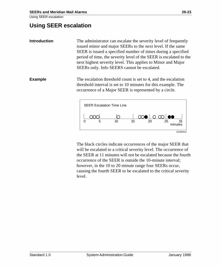
SEERs and Meridian Mail Alarms 29-23Using SEER escalation
ly ed the
at f urth
ity
Using SEER escalation
Introduction The administrator can escalate the severity level of frequentissued minor and major SEERs to the next level. If the sameSEER is issued a specified number of times during a specifiperiod of time, the severity level of the SEER is escalated to next highest severity level. This applies to Minor and Major SEERs only. Info SEERS cannot be escalated.
Example The escalation threshold count is set to 4, and the escalationthreshold interval is set to 10 minutes for this example. The occurrence of a Major SEER is represented by a circle.
The black circles indicate occurrences of the major SEER thwill be escalated to a critical severity level. The occurrence othe SEER at 11 minutes will not be escalated because the fooccurrence of the SEER is outside the 10-minute interval; however, in the 10 to 20 minute range four SEERs occur, causing the fourth SEER to be escalated to the critical severlevel.
SEER Escalation Time Line
0 5 10 15 20 25 15minutes
G100413
Standard 1.0 System Administration Guide January 1998
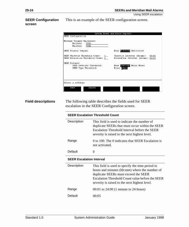
29-24 SEERs and Meridian Mail Alarms Using SEER escalation
R
s
f
R
SEER Configuration screen
This is an example of the SEER configuration screen.
Field descriptions The following table describes the fields used for SEER escalation in the SEER Configuration screen.
SEER Escalation Threshold Count
Description This field is used to indicate the number of duplicate SEERs that must occur within the SEEEscalation Threshold Interval before the SEER severity is raised to the next highest level.
Range 0 to 100. The 0 indicates that SEER Escalation inot activated.
Default 0
SEER Escalation Interval
Description This field is used to specify the time period in hours and minutes (hh:mm) where the number oduplicate SEERs must exceed the SEER Escalation Threshold Count value before the SEEseverity is raised to the next highest level.
Range 00:01 to 24:00 (1 minute to 24 hours)
Default 00:05
Standard 1.0 System Administration Guide January 1998
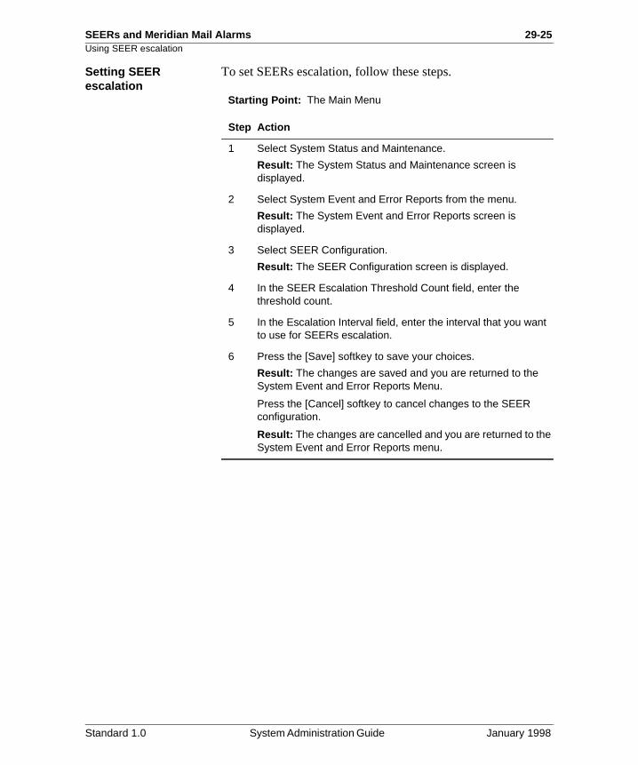
SEERs and Meridian Mail Alarms 29-25Using SEER escalation
Setting SEER escalation
To set SEERs escalation, follow these steps.
Starting Point: The Main Menu
Step Action
1 Select System Status and Maintenance.
Result: The System Status and Maintenance screen is displayed.
2 Select System Event and Error Reports from the menu.
Result: The System Event and Error Reports screen is displayed.
3 Select SEER Configuration.
Result: The SEER Configuration screen is displayed.
4 In the SEER Escalation Threshold Count field, enter the threshold count.
5 In the Escalation Interval field, enter the interval that you want to use for SEERs escalation.
6 Press the [Save] softkey to save your choices.
Result: The changes are saved and you are returned to the System Event and Error Reports Menu.
Press the [Cancel] softkey to cancel changes to the SEER configuration.
Result: The changes are cancelled and you are returned to the System Event and Error Reports menu.
Standard 1.0 System Administration Guide January 1998

29-26 SEERs and Meridian Mail Alarms Using SEER escalation
Standard 1.0 System Administration Guide January 1998
SEERs and Meridian Mail Alarms 29-27
Section C: Notification options for SEERs and alarms
In this section
Overview 29-28
Notification options for SEERs and alarms 29-29
Using SEER filtering 29-31
Using SEER triggering 29-35
SEERs printing 29-38
Setting the SEER printer port name 29-40
Standard 1.0 System Administration Guide January 1998
29-28 SEERs and Meridian Mail Alarms Overview
Overview
Introduction This section describes
• the route that a SEER takes after it is issued by the Meridian Mail system
• using the SEER filtering and triggering features
• setting up printing for SEERs
Standard 1.0 System Administration Guide January 1998
SEERs and Meridian Mail Alarms 29-29Notification options for SEERs and alarms
has
l
r,
R he
ap ER
the
Notification options for SEERs and alarms
Introduction This section describes the route that a SEER follows after it been issued by the Meridian Mail system.
How the Meridian Mail system processes a SEER
The following provides an overview of how the Meridian Maisystem processes a SEER.
1. The SEER is issued by the Meridian Mail system. An audible alarm sounds if the severity level is critical, majoor minor and the alarm feature has been wired on your system.
2. The system scans the memory remap table for the SEEthat has been issued. If the SEER matches an entry in tmemory remap table, the SEER’s severity and type is changed to that of the table entry.
3. If the SEER does not match an entry in the memory remtable, the system scans the SEER remap table. If the SEmatches an entry in the SEER remap table, the SEER’sseverity is changed to that of the table entry.
4. Next, the remapped SEER severity is escalated if the escalation thresholds are exceeded. The SEER is sent toSEER history file.
Standard 1.0 System Administration Guide January 1998
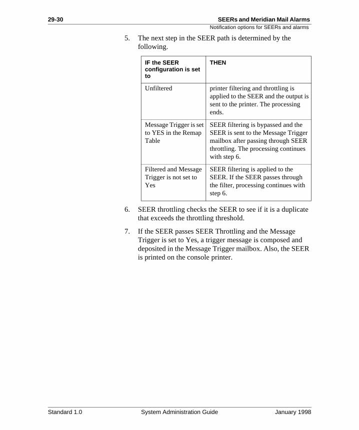
29-30 SEERs and Meridian Mail Alarms Notification options for SEERs and alarms
te
d R
5. The next step in the SEER path is determined by the following.
6. SEER throttling checks the SEER to see if it is a duplicathat exceeds the throttling threshold.
7. If the SEER passes SEER Throttling and the Message Trigger is set to Yes, a trigger message is composed andeposited in the Message Trigger mailbox. Also, the SEEis printed on the console printer.
IF the SEER configuration is set to
THEN
Unfiltered printer filtering and throttling is applied to the SEER and the output issent to the printer. The processing ends.
Message Trigger is set to YES in the Remap Table
SEER filtering is bypassed and the SEER is sent to the Message Triggermailbox after passing through SEER throttling. The processing continues with step 6.
Filtered and Message Trigger is not set to Yes
SEER filtering is applied to the SEER. If the SEER passes through the filter, processing continues with step 6.
Standard 1.0 System Administration Guide January 1998
SEERs and Meridian Mail Alarms 29-31Using SEER filtering
y ce,
the an nter u
R
Using SEER filtering
Introduction SEER filtering parameters allow the administrator to limit thenumber of SEERs sent to the Message Trigger Mailbox. Onlthe SEERs required for proper system operation, maintenanor hacker monitoring activity should be sent to the Message Trigger Mailbox.
The administrator may choose to filter the SEERs based on severity or type of SEER, or both. The filtering parameters calso be used to limit the SEERs that are sent to the SEER priif the appropriate SEER Printer Output option is selected. Yocannot filter individual SEERs or SEER classes.
Filtering by severity levelThe following table describes the filtering possibilities if SEEfiltering is set using the severity level only.
Minimum Severity Level
SEERs sent to Message Trigger Mailbox
None Only those SEERs which have the Message Trigger Field set to YES in the SEER Remap Table.
Critical Only critical SEERs. This is the default value.
Major Only major and critical SEERs.
Minor Minor, major, and critical SEERs.
Note: An appropriate warning appears if Minor isselected, as there is a possibility of flooding theMessage Trigger Mailbox at this level of SEER.
Standard 1.0 System Administration Guide January 1998
29-32 SEERs and Meridian Mail Alarms Using SEER filtering
R
s ger
R t
s
Filtering by SEER typeThe following table describes the filtering possibilities if SEEfiltering is set according to the SEER type only.
Filtering by severity and SEER type
When multiple filtering parameters are set, only those SEERwhich pass through both filters are sent to the Message TrigMailbox.
For example, if the severity level is set to Critical and the SEEtype is set to Error only Critical Error type SEERs will be sento the Message Trigger Mailbox.
SEER type SEERs sent to Message Trigger Mailbox
Error Error SEERs only.Error level SEERs may indicate a system problem which can be corrected by the administrator, perhapwith the assistance of technical support.
Admin Admin and Error SEERs only.The ADMIN level of filtering is designed to allow the administrator to concentrate on those SEERs which are important, and not overload the administrator withinformational SEERs. This will eliminate the nightly audit SEERs, and others which do not require the attention of the typical system administrator.
Standard 1.0 System Administration Guide January 1998
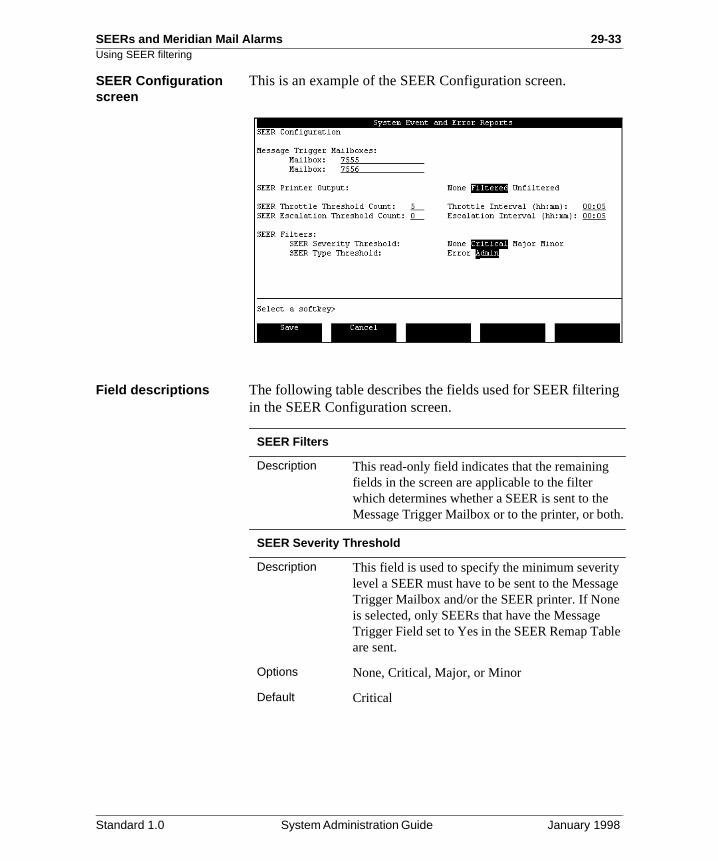
SEERs and Meridian Mail Alarms 29-33Using SEER filtering
g
h.
ge
le
SEER Configuration screen
This is an example of the SEER Configuration screen.
Field descriptions The following table describes the fields used for SEER filterinin the SEER Configuration screen.
SEER Filters
Description This read-only field indicates that the remaining fields in the screen are applicable to the filter which determines whether a SEER is sent to theMessage Trigger Mailbox or to the printer, or bot
SEER Severity Threshold
Description This field is used to specify the minimum severitylevel a SEER must have to be sent to the MessaTrigger Mailbox and/or the SEER printer. If Noneis selected, only SEERs that have the Message Trigger Field set to Yes in the SEER Remap Tabare sent.
Options None, Critical, Major, or Minor
Default Critical
Standard 1.0 System Administration Guide January 1998
29-34 SEERs and Meridian Mail Alarms Using SEER filtering
R
Setting SEER filtering To set SEERs filtering, follow these steps.
Starting Point: The Main Menu
SEER Severity Threshold
Description This field is used to specify the SEER type a SEEmust have to be sent to the Message Trigger Mailbox and/or the SEER printer.
Options Error and Admin
Default Admin
Step Action
1 Select System Status and Maintenance.
Result: The System Status and Maintenance screen is displayed.
2 Select System Event and Error Reports from the menu.
Result: The System Event and Error Reports screen is displayed.
3 Select SEER Configuration.
Result: The SEER Configuration screen is displayed.
4 In the SEER Severity Threshold field, select the severity.
5 In the SEER Type Threshold field, select the type of SEER that you want filtered.
6 Press the [Save] softkey to save your choices.
Result: The changes are saved and you are returned to the System Event and Error Reports menu.
Press the [Cancel] softkey to cancel changes to the SEER configuration.
Result: The changes are cancelled and you are returned to the System Event and Error Reports menu.
Standard 1.0 System Administration Guide January 1998
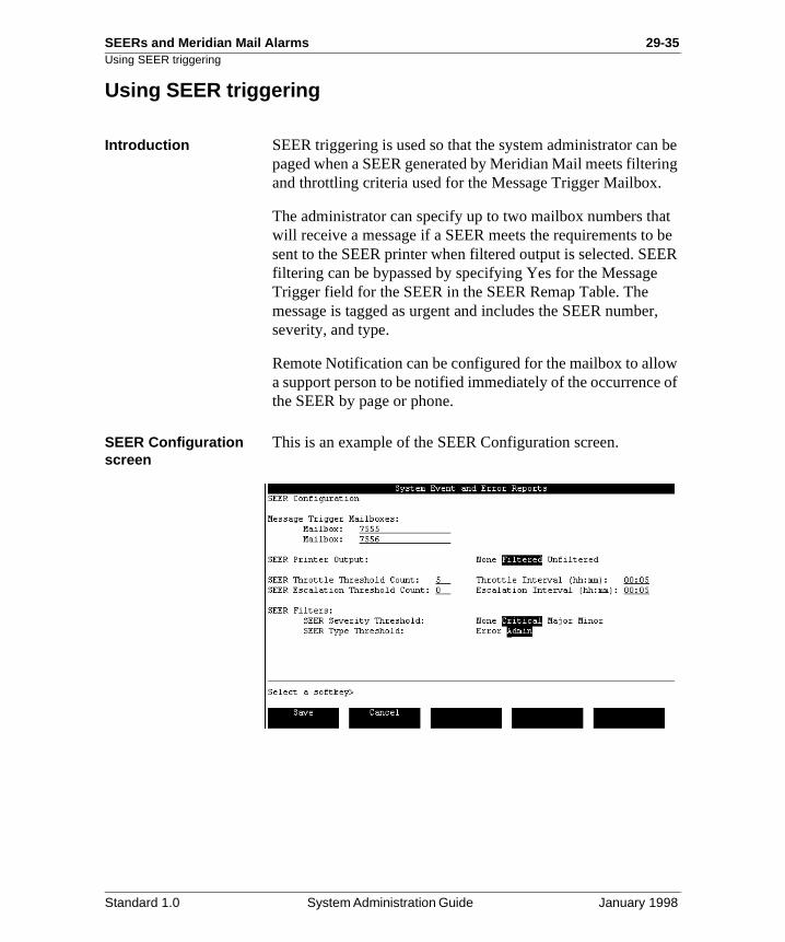
SEERs and Meridian Mail Alarms 29-35Using SEER triggering
be ing
at be ER
r,
w of
Using SEER triggering
Introduction SEER triggering is used so that the system administrator canpaged when a SEER generated by Meridian Mail meets filterand throttling criteria used for the Message Trigger Mailbox.
The administrator can specify up to two mailbox numbers thwill receive a message if a SEER meets the requirements tosent to the SEER printer when filtered output is selected. SEfiltering can be bypassed by specifying Yes for the MessageTrigger field for the SEER in the SEER Remap Table. The message is tagged as urgent and includes the SEER numbeseverity, and type.
Remote Notification can be configured for the mailbox to alloa support person to be notified immediately of the occurrencethe SEER by page or phone.
SEER Configuration screen
This is an example of the SEER Configuration screen.
Standard 1.0 System Administration Guide January 1998
29-36 SEERs and Meridian Mail Alarms Using SEER triggering
f
a rity
g
or
Field descriptions The following table describes the fields used for SEER triggering in the SEER Configuration screen.
Message Trigger Mailboxes
Description This read-only field indicates that the next pair ofields in the screen are applicable to the configuration of the Message Trigger Mailboxes.When a SEER occurs that meets the Trigger requirements (as set in the SEER Filters fields), message containing the SEER number and seveis sent to the mailbox specified belonging to the corresponding customer group specified. (For SEERs related to the Meridian Mail Hacker Monitor, the CLID and mailbox/dialed number areincluded.) These mailboxes can be configured with RemoteNotification to page or phone a person when themessage arrives in the mailbox.
Customer Number
Description The customer number that contains the mailbox that you want to set as the Message Trigger mailbox.
Default 1
Mailbox
Description This is the mailbox number to which the SEER trigger message is sent when the SEER triggerincriteria are met. Validation is performed on the mailbox number to ensure its existence. This mailbox can be either a local voice user mailbox an NMS mailbox (local site mailbox).
Default The field is blank.
Standard 1.0 System Administration Guide January 1998
SEERs and Meridian Mail Alarms 29-37Using SEER triggering
Procedure To set SEERs triggering, follow these steps.
Starting Point: The Main Menu
Step Action
1 Select System Status and Maintenance.
Result: The System Status and Maintenance screen is displayed.
2 Select System Event and Error Reports from the menu.
Result: The System Event and Error Reports screen is displayed.
3 Select SEER Configuration.
Result: The SEER Configuration screen is displayed.
4 In the Message Trigger Mailboxes field, enter the mailbox or mailboxes where the message is to be sent.
5 Check that the correct SEERs Filters have been set. (See “Setting SEER filtering” on page 29-34.)
6 Press the [Save] softkey to save your choices.
Result: The changes are saved and you are returned to the System Event and Error Reports Menu.
Press the [Cancel] softkey to cancel changes to the SEER configuration.
Result: The changes are cancelled and you are returned to the System Event and Error Reports menu.
Standard 1.0 System Administration Guide January 1998
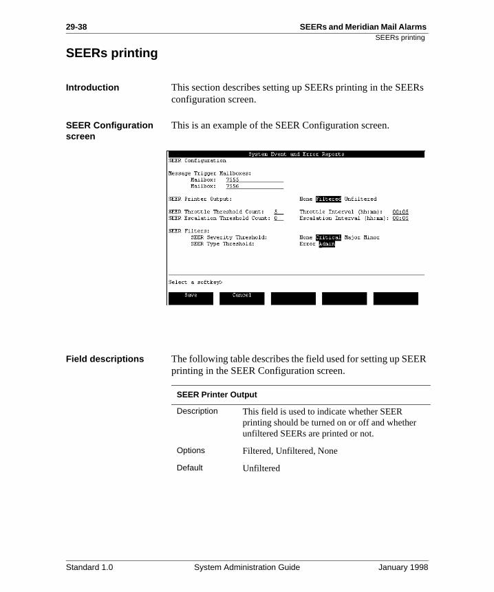
29-38 SEERs and Meridian Mail Alarms SEERs printing
Rs
R
SEERs printing
Introduction This section describes setting up SEERs printing in the SEEconfiguration screen.
SEER Configuration screen
This is an example of the SEER Configuration screen.
Field descriptions The following table describes the field used for setting up SEEprinting in the SEER Configuration screen.
SEER Printer Output
Description This field is used to indicate whether SEER printing should be turned on or off and whether unfiltered SEERs are printed or not.
Options Filtered, Unfiltered, None
Default Unfiltered
Standard 1.0 System Administration Guide January 1998
SEERs and Meridian Mail Alarms 29-39SEERs printing
Setting SEERs printing
To set up SEERs printing, follow these steps.
Starting Point: The Main Menu
Step Action
1 Select System Status and Maintenance.
Result: The System Status and Maintenance screen is displayed.
2 Select System Event and Error Reports from the menu.
Result: The System Event and Error Reports screen is displayed.
3 Select SEER Configuration.
Result: The SEER Configuration screen is displayed.
4 In the SEER Printer Output field, select None, Filtered, or Unfiltered.
5 Press the [Save] softkey to save your choice.
Result: The changes are saved and you are returned to the System Event and Error Report screen.
Press the [Cancel] softkey to cancel changes to the SEER configuration.
Result: The changes are cancelled and you are returned to the System Event and Error Reports menu.
Standard 1.0 System Administration Guide January 1998
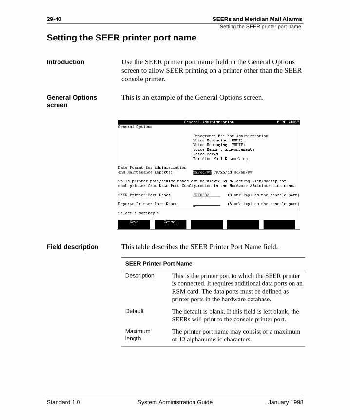
29-40 SEERs and Meridian Mail Alarms Setting the SEER printer port name
ER
an
Setting the SEER printer port name
Introduction Use the SEER printer port name field in the General Optionsscreen to allow SEER printing on a printer other than the SEconsole printer.
General Options screen
This is an example of the General Options screen.
Field description This table describes the SEER Printer Port Name field.
SEER Printer Port Name
Description This is the printer port to which the SEER printeris connected. It requires additional data ports on RSM card. The data ports must be defined as printer ports in the hardware database.
Default The default is blank. If this field is left blank, the SEERs will print to the console printer port.
Maximum length
The printer port name may consist of a maximumof 12 alphanumeric characters.
Standard 1.0 System Administration Guide January 1998
SEERs and Meridian Mail Alarms 29-41Setting the SEER printer port name
es
Procedure To set or change the SEER printer port name values, follow these steps.
Note: Remember that not specifying a printer port name implisending the SEERS printing to the console.
Starting Point: The Main Menu
Step Action
1 Select General Administration from the Main Menu.
Result: The General Administration screen is displayed.
2 Select General Options from the General Administration menu.
Result: The General Options screen is displayed.
3 Use the cursor keys to move to the SEER printer name field.
4 Enter a port name in the SEER Printer Port Name field.
Note: If this field is left blank, SEERs printing is done on the console.
5 Use the softkeys to save or cancel the changes.
• Press [Save].
Result: The changes are saved, and you are returned to the General Administration screen.
• Press [Cancel].
Result: The changes are not saved, and you are returned to the General Administration screen.
Standard 1.0 System Administration Guide January 1998

29-42 SEERs and Meridian Mail Alarms Setting the SEER printer port name
Standard 1.0 System Administration Guide January 1998
Chapter 30
Operational Measurements
In this chapter
Overview 30-2
Section A: Overview of Operational Measurements (OM) 30-3
Section B: Setting up Operational Measurements 30-11
Section C: Interpreting Operational Measurements 30-25
30-2 Operational Measurements Overview
rts M
ful.
Overview
Introduction This chapter describes Operational Measurement (OM) repoand the procedures required to gather, store, and analyze Oinformation.
Section A: Overview of Operational Measurements (OM), describes Operational Measurements and how they are use
Section B: Setting up Operational Measurements, provides information required to set up Meridian Mail so that the Operational Measurements data is gathered and stored.
Section C: Interpreting Operational Measurements, providesprocedures and guidelines for interpreting Operational Measurement reports.
Standard 1.0 System Administration Guide January 1998
Operational Measurements 30-3
Section A: Overview of Operational Measurements (OM)
In this section
Overview 30-4
What are Operational Measurements? 30-5
How Operational Measurements are useful 30-7
Standard 1.0 System Administration Guide January 1998
30-4 Operational Measurements Overview
ides
Overview
Introduction This section describes Operational Measurements and provinformation about their use.
Standard 1.0 System Administration Guide January 1998
Operational Measurements 30-5What are Operational Measurements?
an
e
nd o low
he er
,
r 32,
h
on
What are Operational Measurements?
Introduction The Operational Measurement (OM) reports allow administrators and Nortel support staff to study how a MeridiMail system is being used. These reports may be used to determine if a change in the system is required to improve thlevel of service provided by Meridian Mail. For example, if overall traffic on the system is higher than was originally anticipated, a channel expansion may be necessary.
OM reports also show which features are being used a lot, awhich features are not being used at all. OM reports can alsreveal potential technical problems with the system, such as disk space (the amount of disk space affects Meridian Mail’sability to store messages and perform its functions).
Traffic reports Traffic reports shows how much the system is being used. Treports identify the number of calls processed, and the numbof times users log in to Meridian Mail or access particular features such as Voice Messaging, Voice Menu applicationsand Outcalling. For detailed descriptions, examples, and analyses of available traffic reports, see Chapter 31, “Operational Measurements traffic reports”.
User Usage reports User Usage reports monitor how specific users employ voicemessaging, Meridian Networking (if installed), and AMIS Networking (if installed). Information is broken down to showuser activity on a daily basis. For detailed descriptions, examples, and analyses of User Usage reports, see Chapte“User Usage reports”.
Outcalling Audit Trail reports
Outcalling Audit Trail reports provide you with statistics that allow you to monitor the use of Remote Notification (RN) andDelivery to Non-User (DNU) features. Two different reports can be generated: a summary report and a detail report. Eacreport provides statistics for a certain period of time (as specified by you) by user’s name and mailbox. The informatiin the summary report helps in problem determination. The detail report provides call detail records that allow you to
Standard 1.0 System Administration Guide January 1998
30-6 Operational Measurements What are Operational Measurements?
of
y a he
ts,
troubleshoot outcalling problems. For a detailed description these reports, see Chapter 33, “Audit Trail reports”.
Fax Audit Trail reports Fax Audit Trail reports provide you with statistics that allow you to monitor how users are using the Fax on Demand features. Two different reports can be generated: a summarreport and a detail report. Each report provides statistics for certain time period (as specified by you). The information in tsummary report helps in problem determination. The detail report provides call detail records that allow you to trouble shoot fax problems. For a detailed description of these reporsee Chapter 33, “Audit Trail reports”.
Standard 1.0 System Administration Guide January 1998
Operational Measurements 30-7How Operational Measurements are useful
use an
ian ow.
r . k the nd in
How Operational Measurements are useful
Overview The information that follows describes ways of using Operational Measurements (OM) report statistics.
Using OM to monitor system usage
You can use OM reports to monitor how the system is beingused. For example, you can use these reports to determine which features are being used and which are not, and if the of the system matches what the expectations were when thesystem size was being determined. If the system is busier thwas anticipated, then you may need to expand the system.
Using OM to detect potential system problems
Similarly, OM reports can also be used to identify potential system problems, and possibly the cause of the problems. Although you should always use input from the users of the system to help determine if there is a problem, OM reports provide more definite data to work with.
ExampleIf callers or users complain that they cannot access the MeridMail system, channels may be tied up or disk space may be lOM reports can help you determine if the problem is with system capacity or inefficient usage.
Potential problems that can be detected using OM
Some of the potential problems that can be detected throughOM reports are discussed in the following examples.
Example 1: Disk space lowIf the voice space used on a disk volume is consistently oveyour disk usage warning level, then disk space is getting lowSteps should be taken to reduce the voice space used. ChecVoice Space Used column of the Disk Usage Detail report, asee “Analyzing the Disk Usage Detail report” on page 31-54 Chapter 31.
Standard 1.0 System Administration Guide January 1998
30-8 Operational Measurements How Operational Measurements are useful
and is e
f
t
o
to e w
e.
he ths
Potential problems (cont’d)
Example 2: Channels busyThe Channel Usage Detail report shows the number of calls voice mail usage (in CCS) per channel. If the number of callshigh or the average message length is exceptionally long, thchannels may be too busy to handle all incoming calls. As a result, users may not be able to access Meridian Mail. Several of the “Analyzing” sections that follow the sample reports refer to analyzing or dealing with high traffic problems.
Example 3: Inefficient usageThe Services Summary Traffic report provides an overview ohow much your Meridian Mail features are being used. If younotice that some features are not being used at all, this mayindicate that the users are not aware of the feature (or do noknow how to use it), or that the feature is not required. The users may require more training. Use broadcast messages tgive brief pointers or to inform users of available training courses or material.
Example 4: Unauthorized usageIf the Thru-Dial feature is being accessed more frequently during off-hours or if the average length of the Thru-Dial sessions is long, this may indicate that unauthorized users (hackers) are accessing your Meridian Mail system in order use the Thru-Dial feature (for example, to make long distanccalls). If you notice unusual use of the Thru-Dial feature, reviethe dialing restrictions for Thru-Dial (refer to the Voice Services Application Guide [NTP 555-7001-325] for details). Also, if you are using an access password for Thru-Dial, change theaccess password and continue to monitor the Thru-Dial usagFor more information, see “Services Summary report” in Chapter 31, “Operational Measurements traffic reports”, for tnumber of Thru-Dial sessions and the average session lengduring specific time periods.
Standard 1.0 System Administration Guide January 1998
Operational Measurements 30-9How Operational Measurements are useful
s
g. il
nal
is
e to n
one
nt asis
Using OM as a billing tool
As an accounting and billing tool, Operational Measurementare used to generate the daily user billing files (for local activity). Use the User Usage reports to compile data for billinIf you have the AdminPlus feature installed, use Meridian MaReporter (MMR) to compile data for billing.
If your organization does not bill users of Meridian Mail, you may not need to use the User Usage component of OperatioMeasurements. However, it can also be used for tracking problems or history or for security reasons (for example, whologging on and receiving messages).
Using OM as a capacity planning tool
As a capacity planning tool, Operational Measurements are used to generate traffic reports that you subsequently analyzdetermine whether your system requires an upgrade either idisk storage, channel capacity, or perhaps in the number of nodes (should the number of users on your system approachof the limits discussed in the Messaging Overview [NTP 555-7001-100]). If your organization’s use of Meridian Mail is fairly stable, you need only use the traffic measuremecomponent of Operational Measurements on an infrequent bto verify that the system’s resources are adequate for your needs.
Standard 1.0 System Administration Guide January 1998

30-10 Operational Measurements How Operational Measurements are useful
Standard 1.0 System Administration Guide January 1998
Chapter 30
Operational Measurements 30-11Section B: Setting up Operational Measurements
In this section
Overview 30-12
Using the Operational Measurements menu 30-13
Calculating disk space required for OM data storage 30-15
Operational Measurements Options screen 30-19
Fields in the Operational Measurement Options screen 30-21
Setting Meridian Mail to collect and receive data 30-24
Standard 1.0 System Administration Guide January 1998
30-12 Operational Measurements
n the
Overview
Overview
Introduction This section describes the procedures for setting up MeridiaMail Operational Measurements. These procedures include following:
• using the Operational Measurements menu
• calculating disk space required for OM data storage
• setting Meridian Mail to collect and receive data
Standard 1.0 System Administration Guide January 1998
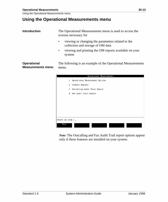
Operational Measurements 30-13Using the Operational Measurements menu
ts
ar
Using the Operational Measurements menu
Introduction The Operational Measurements menu is used to access thescreens necessary for
• viewing or changing the parameters related to the collection and storage of OM data
• viewing and printing the OM reports available on your system
Operational Measurements menu
The following is an example of the Operational Measuremenmenu.
Note: The Outcalling and Fax Audit Trail report options appeonly if these features are installed on your system.
Standard 1.0 System Administration Guide January 1998
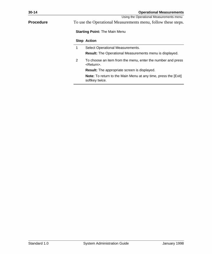
30-14 Operational Measurements
teps.
Using the Operational Measurements menuProcedure To use the Operational Measurements menu, follow these s
Starting Point: The Main Menu
Step Action
1 Select Operational Measurements.
Result: The Operational Measurements menu is displayed.
2 To choose an item from the menu, enter the number and press <Return>.
Result: The appropriate screen is displayed.
Note: To return to the Main Menu at any time, press the [Exit] softkey twice.
Standard 1.0 System Administration Guide January 1998
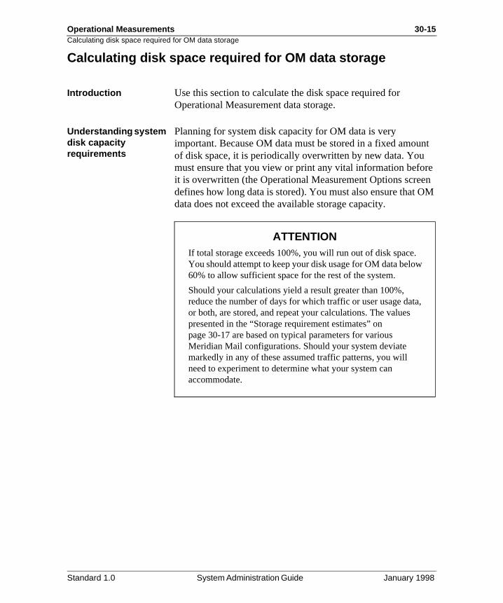
Operational Measurements 30-15Calculating disk space required for OM data storage
nt
re en OM
Calculating disk space required for OM data storage
Introduction Use this section to calculate the disk space required for Operational Measurement data storage.
Understanding system disk capacity requirements
Planning for system disk capacity for OM data is very important. Because OM data must be stored in a fixed amouof disk space, it is periodically overwritten by new data. You must ensure that you view or print any vital information befoit is overwritten (the Operational Measurement Options scredefines how long data is stored). You must also ensure that data does not exceed the available storage capacity.
ATTENTIONIf total storage exceeds 100%, you will run out of disk space. You should attempt to keep your disk usage for OM data below60% to allow sufficient space for the rest of the system.
Should your calculations yield a result greater than 100%, reduce the number of days for which traffic or user usage data,or both, are stored, and repeat your calculations. The values presented in the “Storage requirement estimates” on page 30-17 are based on typical parameters for various Meridian Mail configurations. Should your system deviate markedly in any of these assumed traffic patterns, you will need to experiment to determine what your system can accommodate.
Standard 1.0 System Administration Guide January 1998
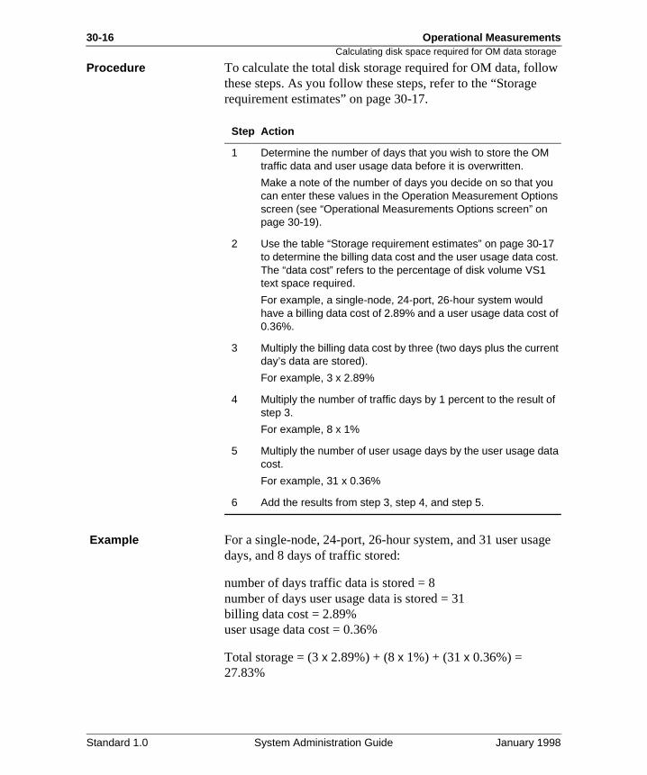
30-16 Operational Measurements
w
ge
Calculating disk space required for OM data storage
Procedure To calculate the total disk storage required for OM data, follothese steps. As you follow these steps, refer to the “Storagerequirement estimates” on page 30-17.
Example For a single-node, 24-port, 26-hour system, and 31 user usadays, and 8 days of traffic stored:
number of days traffic data is stored = 8number of days user usage data is stored = 31billing data cost = 2.89%user usage data cost = 0.36%
Total storage = (3 x 2.89%) + (8 x 1%) + (31 x 0.36%) = 27.83%
Step Action
1 Determine the number of days that you wish to store the OM traffic data and user usage data before it is overwritten.
Make a note of the number of days you decide on so that you can enter these values in the Operation Measurement Options screen (see “Operational Measurements Options screen” on page 30-19).
2 Use the table “Storage requirement estimates” on page 30-17 to determine the billing data cost and the user usage data cost. The “data cost” refers to the percentage of disk volume VS1 text space required.
For example, a single-node, 24-port, 26-hour system would have a billing data cost of 2.89% and a user usage data cost of 0.36%.
3 Multiply the billing data cost by three (two days plus the current day’s data are stored).
For example, 3 x 2.89%
4 Multiply the number of traffic days by 1 percent to the result of step 3.
For example, 8 x 1%
5 Multiply the number of user usage days by the user usage data cost.
For example, 31 x 0.36%
6 Add the results from step 3, step 4, and step 5.
Standard 1.0 System Administration Guide January 1998
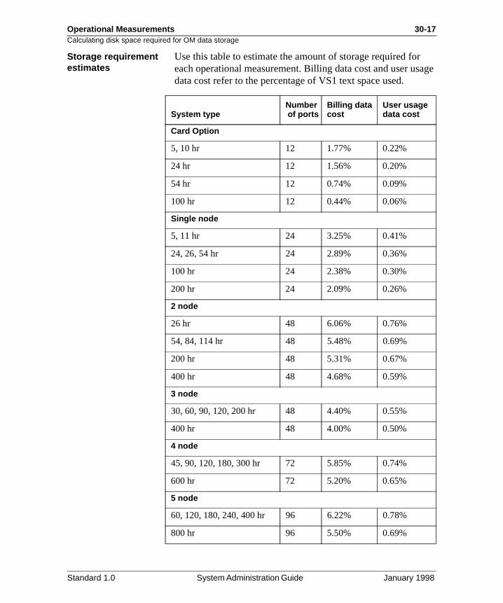
Operational Measurements 30-17Calculating disk space required for OM data storage
age
Storage requirement estimates
Use this table to estimate the amount of storage required foreach operational measurement. Billing data cost and user usdata cost refer to the percentage of VS1 text space used.
System typeNumber of ports
Billing data cost
User usage data cost
Card Option
5, 10 hr 12 1.77% 0.22%
24 hr 12 1.56% 0.20%
54 hr 12 0.74% 0.09%
100 hr 12 0.44% 0.06%
Single node
5, 11 hr 24 3.25% 0.41%
24, 26, 54 hr 24 2.89% 0.36%
100 hr 24 2.38% 0.30%
200 hr 24 2.09% 0.26%
2 node
26 hr 48 6.06% 0.76%
54, 84, 114 hr 48 5.48% 0.69%
200 hr 48 5.31% 0.67%
400 hr 48 4.68% 0.59%
3 node
30, 60, 90, 120, 200 hr 48 4.40% 0.55%
400 hr 48 4.00% 0.50%
4 node
45, 90, 120, 180, 300 hr 72 5.85% 0.74%
600 hr 72 5.20% 0.65%
5 node
60, 120, 180, 240, 400 hr 96 6.22% 0.78%
800 hr 96 5.50% 0.69%
Standard 1.0 System Administration Guide January 1998
30-18 Operational Measurements
ht-
Calculating disk space required for OM data storage
Traffic assumptionsThe preceding table is based on a typical system with an eighour business day, and the following traffic:
• 25% of the time at busy hour traffic (2 hours)
• 5% of the time at greater than busy hour traffic (25 minutes)
• 70% of the time at less than 75% of busy hour traffic (5 hours and 35 minutes)
• average call holding time of 40 seconds
Standard 1.0 System Administration Guide January 1998
Operational Measurements 30-19Operational Measurements Options screen
e s
lly
Operational Measurements Options screen
Introduction The Operational Measurement Options screen is used by thsystem administrator to define how system and user statisticare collected. This includes the time at which traffic data collection begins and ends every day, how often collected traffic statistics are written to disk, and whether or not traffic data, user usage data, or audit trail data is collected. Also included are the number of days of data that are stored for traffic, user usage data, and audit trail reports, and the percentage at which audit trail data collection will automaticabe disabled.
Note: If the AdminPlus/Meridian Mail Reporter option is installed, it is important that a minimum set of OMs are collected. Refer to the Meridian Mail Reporter 2.0 User’s Guide (P0847870).
Standard 1.0 System Administration Guide January 1998
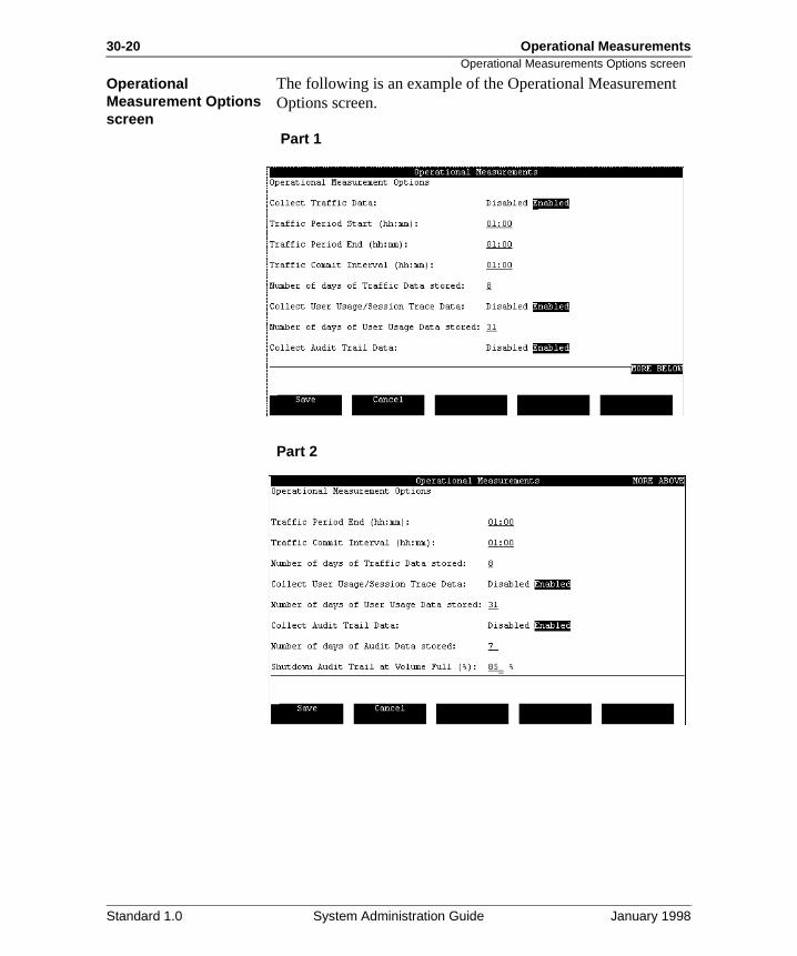
30-20 Operational Measurements
t
Operational Measurements Options screenOperational Measurement Options screen
The following is an example of the Operational MeasuremenOptions screen.
Part 1
Part 2
Standard 1.0 System Administration Guide January 1998
Operational Measurements 30-21Fields in the Operational Measurement Options screen
l
he
ed .
is
on
d ill 0.
0.
fic
nd ed
s
Fields in the Operational Measurement Options screen
Overview The following section describes the fields on the OperationaMeasurement Options screen.
Collect Traffic Data When this field is Enabled, a statistical record of voice messaging and other voice services, voice channel traffic, Meridian Networking and AMIS Networking message traffic,and disk space usage will be collected and stored on disk. Tdefault is Enabled.
Traffic Period Start (hh:mm)
This is for the time at which data begins to be collected, bason the 24-hour clock. The valid range is from 00:00 to 23:30You may enter values only in half-hour increments, for example, 01:00, 01:30; 02:00, 02:30, and so on. The default01:00.
Traffic Period End (hh:mm)
This is for the time at which data stops being collected, basedthe 24-hour clock. To continuously collect traffic data, set thePeriod Start field equal to the Period End field (that is, PerioStart = 01:00 and Period End = 01:00). In this manner, data wbe collected 24 hours a day. The valid range is 00:00 to 23:3You may enter values only in half-hour increments, for example, 01:00, 01:30; 02:00, and 02:30. The default is 01:0
Traffic Commit Interval (hh:mm)
The value in this field determines how often the collected trafstatistics are written to the hard disk within the defined trafficperiod. The default is 01:00. The valid range is from 00:00 to23:30.
Commit intervals should be entered in half-hour increments abe equally divisible into the period range. The smallest allowinterval is 30 minutes. However, a one-hour interval will provide similar granularity of data and will require only half amany writes to disk (resulting in less disk usage) as the 30-minute interval.
Standard 1.0 System Administration Guide January 1998
30-22 Operational Measurements
ly, nd t
o . If
te st
e ot id
e for to
’s d
Fields in the Operational Measurement Options screen
ExampleIf the Collect Traffic Data field is set to Enabled and
Traffic Period Start = 08:00,Traffic Period Stop = 17:00,Traffic Commit Interval = 1:30,
traffic data is collected between 8:00 a.m. and 5:00 p.m. daiand traffic reports are written to the hard disk every 1 hour a30 minutes during this period. The first report is written out a9:30 a.m. and the last one is written out at 5:00 p.m.
Note: The traffic commit interval can be set to 24 hours. However, an interval greater than two hours is not recommended because the accumulated numbers may be tolarge to be accommodated by the fields in the report screensa number is too large, >999 is displayed in the field to indicaoverflow. Furthermore, any data that is not written to disk is loif a system reboot occurs.
Number of days of Traffic Data stored
This field determines the number of days that traffic data is maintained before being overwritten by new traffic data.
ExampleIf this field is set to 8, on the 9th day you will not be able to view traffic data collected on the first day as it will have beenoverwritten, but you will be able to view the data from the remaining eight days. The old traffic data is removed from thdisk at 1:20 a.m. each day. The data for the current day is nincluded in the number of days of traffic data stored. The valrange is 1 to 8 days. The default is 8 days.
Collect User Usage/Session Trace Data
This field controls the collection of both user usage data andsession trace data. Session trace data includes detailed voicmessaging session statistics. The session statistics are kepttwo days, regardless of how long you define user usage databe stored. (For example, on Monday you can view Saturdaydata, but not Friday’s data.) Session reports can be accesseusing the Session Trace tool (refer to System Administration Tools [NTP 555-7001-305]). The default is Enabled.
Standard 1.0 System Administration Guide January 1998
Operational Measurements 30-23Fields in the Operational Measurement Options screen
ry
rts or r call
d
s
a
d d is
ice ult
Number of days of User Usage Data stored
This field controls the number of days of user usage summastatistics data that is kept on the hard disk before it is overwritten. The range is from 1 to 63. The default is 31.
Collect Audit Trail Data
This field appears only if Outcalling or Fax On Demand is installed. When this field is set to Enabled, Outcalling or FaxAudit Trail reports are generated by the system. These repocan be used to obtain information about a specific outcallingfax callback session. The reports give you either summary odetailed information about the number of calls, the start timeand duration of calls, the numbers called, and details of the status. The default is Enabled. See Chapter 33, “Audit Trail reports,” in this guide for more information.
Number of Days of Audit Data stored
This field appears only if either Outcalling or Fax On Demanis installed. This field is used if the Collect Audit Trail Data field is set to Enabled. This field indicates the number of daythe audit trail data will be stored on disk before being overwritten. The number of days can range from 1 to 63, withdefault of 7.
Shutdown Audit Trail at Volume Full (%)
This field appears only if either Outcalling or Fax On Demanis installed.This field is used if the Collect Audit Trail Data fielis set to Enabled. When the volume on which audit trail datastored meets this percentage, collection of audit trail data is disabled. (Note that this is a percentage of text space, not vospace.) The range for this field is from 1% to 100%. The defais 85%.
OM Collection ACCESS Class
This field indicates the class number of the ACCESS application for which Operational Measurements should be collected. The valid range for this number is 0 to 8999. It is primarily intended to be used to collect messenger desktop access of Meridian Mail ports.
Note: This field is available only if ACCESS is installed.
Standard 1.0 System Administration Guide January 1998
30-24 Operational Measurements
the
se
Setting Meridian Mail to collect and receive data
Setting Meridian Mail to collect and receive data
Introduction Use the Operational Measurement Options screen to defineparameters for collecting the OM information from your Meridian Mail system.
Procedure To set the Operational Measurement parameters, follow thesteps.
Starting Point: The Operational Measurements menu
Step Action
1 Select Operational Measurements.
Result: The Operational Measurement Options screen appears.
2 Set the parameters as required. For information on setting these parameters, see “Fields in the Operational Measurement Options screen” on page 30-21.
3 Choose step 4 to save the changes or step 5 to cancel.
4 Press [Save].
Result: The changes are saved and the Operational Measurements menu is redisplayed.
Note: Any saved changes force all traffic data to be committed at the time of the save, regardless of the interval and period specified. This action will also create an irregular time period (the time up to the save) that will appear on the traffic reports. Also, a SEER is issued to indicate that the changes have taken effect.
5 Press [Cancel].
Result: Any changes you have made are discarded; the Operational Measurements menu is redisplayed.
Standard 1.0 System Administration Guide January 1998
Chapter 30
Operational Measurements 30-25Section C: Interpreting Operational Measurements
In this section
Overview 30-26
Calculating centi-call seconds 30-27
Interpretation guidelines 30-28
Standard 1.0 System Administration Guide January 1998
30-26 Operational Measurements
nd
Overview
Overview
Introduction This section describes the calculation of centi-call seconds aprovides guidelines that are useful when interpreting OM reports.
Standard 1.0 System Administration Guide January 1998
Operational Measurements 30-27Calculating centi-call seconds
nds,
100 on
re
e
r
Calculating centi-call seconds
Introduction Many of the OM reports provide usage time in centi-call seconds. Centi-call seconds (CCS), or hundreds of call secocan be calculated using the formula in this section.
Definition CCS is a traffic measurement statistic. One CCS is equal to seconds of call connection time per hour. The CCS is basedthe total number of call seconds, not the average length, multiplied by the number of accesses.
Formula To calculate the CCS value, use the following formula.
The first part of the formula compensates for intervals that anot one hour.
Examples320 total call seconds during a half-hour interval produces thfollowing CCS:
If the interval is one hour, the first part of the formula can beignored. For example, 320 total call seconds over a one-houinterval produces the following CCS:
CCS = 60 minutes
interval (in minutes)
total call seconds
100 secondsx
~~CCS = 60 minutes 320 seconds
100 secondsx
30 minutes= 2 x 3.2 = 6.4 6
~~CCS = 60 minutes 320 seconds
100 secondsx
60 minutes= 1 x 3.2 = 3.2 3
Standard 1.0 System Administration Guide January 1998
30-28 Operational Measurements
ould of
ty.
ip l t,
nd e
d
nto
s ay
Interpretation guidelines
Interpretation guidelines
Introduction When interpreting the OM reports, consider the following guidelines.
Service counts Look not only at the counts for each service but also at the relationship between the counts for different services.
ExampleBoth Express Messaging and Call Answering features allowmessages to be left in the system. Therefore, both counts shbe taken into consideration when looking at the total numberincoming messages during a particular time period.
System size Know the size of the system, both channels and disk capaciSmaller systems will be much more sensitive to high traffic counts and durations than larger systems.
How your organization uses the system
Know how your organization uses the system.
Many of the counts and durations will have a direct relationshto how the organization uses the system as part of its overaloperation (for example, voice messaging only, auto attendanmenus, and so on). If you do not know how the organizationfunctions, find someone within the organization who does, ainterpret the information together. That person will provide thnecessary knowledge about how the organization works, anyou can provide the information about the system.
If there is unusual system activity
Make sure you have taken any unusual operational activity iconsideration.
For example, is it a national holiday? an election day? or wathere a major news event recently? Such unusual activities mcause an abnormal usage of your system that will distort thefigures.
Standard 1.0 System Administration Guide January 1998
Operational Measurements 30-29Interpretation guidelines
ary
can h , sis
s due
n.
ue
Report relationships Many reports relate to one another.
For instance, the Services Summary report provides a summof the voice menus, fax, announcement traffic, and other services, but the Services Detail report provides much moredetail about particular services. Know what reports a system produce, and know which ones relate to others. Read througeach report and move back and forth through the informationmaking sure you have optimized the interpretation and analyprocess.
User consultation Consult the users of the system to gain further insight into a report’s findings.
Find out how the system is working for the users and if they have any problems to report. Some apparent system problemmay be the result of improper usage of the system (perhapsto lack of training or awareness of certain system features).
Impact of new features or services
Consider how long a feature or service has been in operatio
When something is new, it may generate more traffic than normal as a result of curiosity, or it may generate less traffic dto lack of familiarity with the new feature, so the initial figuresmay be distorted.
Working with multiple Meridian Mail systems
Ιf you are working with numerous Meridian Mail systems, remember that each Meridian Mail system is unique.
Make sure you apply all the previously described guidelines separately to each system.
Standard 1.0 System Administration Guide January 1998

30-30 Operational Measurements
Interpretation guidelinesStandard 1.0 System Administration Guide January 1998
Chapter 31
Operational Measurements traffic reports
In this chapter
Overview 31-2
Section A: Generating traffic reports 31-3
Section B: Traffic reports 31-9
31-2 Operational Measurements traffic reports Overview
ed,
e
that
s
Overview
Introduction This chapter is devoted to Operational Measurement (OM) traffic reports. These reports show how much the system is being used. The reports identify the number of calls processand the number of times a user logs in to Meridian Mail or accesses particular features such as Voice Messaging, VoicMenu applications, and Outcalling.
Section A: Generating traffic reports, describes how to generate, view, and print OM traffic reports. The section alsodescribes the Traffic Reports screen, which lists the reports can be generated.
Section B: Traffic reports, provides descriptions and analysefor all of these reports.
Standard 1.0 System Administration Guide January 1998
Chapter 31
Operational Measurements traffic reports 31-3Section A: Generating traffic reports
In this section
Overview 31-4
Traffic Reports screen 31-5
Generating traffic reports 31-7
Standard 1.0 System Administration Guide January 1998
31-4 Operational Measurements traffic reports
. fic ffic
Overview
Overview
Introduction This section describes the Traffic Reports screen and the procedure for generating, viewing, and printing traffic reportsAll traffic reports that can be generated are listed on the TrafReport screen. For descriptions and analyses for all of the trareports, see Section B: Traffic reports, on page 31-9.
Standard 1.0 System Administration Guide January 1998
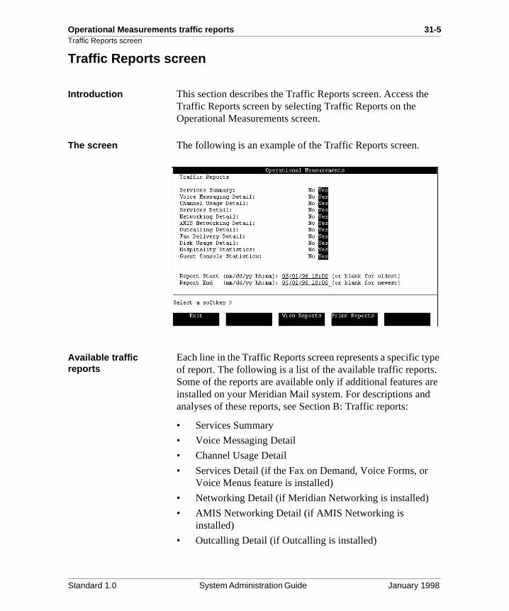
Operational Measurements traffic reports 31-5Traffic Reports screen
e
ype . re
Traffic Reports screen
Introduction This section describes the Traffic Reports screen. Access thTraffic Reports screen by selecting Traffic Reports on the Operational Measurements screen.
The screen The following is an example of the Traffic Reports screen.
Available traffic reports
Each line in the Traffic Reports screen represents a specific tof report. The following is a list of the available traffic reportsSome of the reports are available only if additional features ainstalled on your Meridian Mail system. For descriptions andanalyses of these reports, see Section B: Traffic reports:
• Services Summary
• Voice Messaging Detail
• Channel Usage Detail
• Services Detail (if the Fax on Demand, Voice Forms, or Voice Menus feature is installed)
• Networking Detail (if Meridian Networking is installed)
• AMIS Networking Detail (if AMIS Networking is installed)
• Outcalling Detail (if Outcalling is installed)
Standard 1.0 System Administration Guide January 1998
31-6 Operational Measurements traffic reports
)
Traffic Reports screen
• Fax Delivery Detail (if Fax on Demand is installed)
• Disk Usage Detail
• Hospitality Statistics (if the Hospitality feature is installed
• Guest Console Statistics (if the Hospitality feature is installed)
Standard 1.0 System Administration Guide January 1998
Operational Measurements traffic reports 31-7Generating traffic reports
ich of
Generating traffic reports
Introduction This section describes the procedure for generating traffic reports. The Traffic Reports screen allows you to choose whreports you want to view and print. Also, you have the optionchoosing a Report Start and Report End date and time.
Procedure To generate traffic reports, follow these steps.
Starting Point: The Operational Measurements screen
Step Action
1 Select Traffic Reports from the Operational Measurements screen.
Result: The Traffic Reports screen displays.
2 Move the cursor to the report titles you wish to view or print. Use the arrow keys to toggle the field value to Yes.
3 (This step is optional.) Specify start and stop times for the report period by entering the values in the Report Start (mm/dd/yy hh:mm) and Report End (mm/dd/yy hh:mm) fields. (The format mm/dd/yy hh:mm is the default. The format can be changed in General Administration, General Options. For more information, see Chapter 13, “General options”.
Note: The values you enter are based on the 24-hour clock. The valid range is from 00:00 to 23:59 (12:00 midnight to 11:59 p.m.). If the Report Start and Report End fields are left blank, the defaults of start of available data and end of available data are used respectively.
4 Go to step 5 to view the reports on the terminal, step 6 to print the reports, or step 7 to cancel.
Standard 1.0 System Administration Guide January 1998
31-8 Operational Measurements traffic reports
Generating traffic reports5 Press [View Reports].
Result: The selected report screens are displayed one at a time. Follow the instructions in the table below to view the next report, exit the screen, or view the next page in the same report.
For descriptive and analytical information on individual reports, see Section B: Traffic reports, on page 31-9.
6 Press [Print Reports].
Result: You are prompted to ensure the printer is ready and online.
During printing, you have two options available.
Note: There may be some delay before control is returned to the screen because it waits for the printer to stop printing.
7 Press [Exit].
Result: The Operational Measurements menu is displayed again.
Step Action
IF you want to THEN press softkey
leave the current report and go to the next report
[Next Report].
exit all reports and return to the Traffic Reports screen
[Exit].
view subsequent pages of the current report (if available)
[Next Page].
IF you want to THEN press softkey
print the reports [Continue Printing].
cancel printing at any time [Cancel Printing].
Standard 1.0 System Administration Guide January 1998
Chapter 31
Operational Measurements traffic reports 31-9Section B: Traffic reports
In this section
Overview 31-11
Services Summary report 31-12
Fields in the Services Summary report 31-13
Analyzing the Services Summary report 31-15
Voice Messaging Detail report 31-18
Fields in the Voice Messaging Detail report 31-19
Analyzing the Voice Messaging Detail report 31-21
Channel Usage Detail report 31-22
Fields in the Channel Usage Detail report 31-23
Analyzing the Channel Usage Detail report 31-25
Services Detail report 31-26
Fields in the Services Detail report 31-27
Analyzing the Services Detail report 31-29
Networking Detail report 31-31
Fields in the Networking Detail report 31-32
Analyzing the Networking Detail report 31-35
AMIS Networking Detail report 31-37
Fields in the AMIS Networking Detail report 31-38
Analyzing the AMIS Networking Detail report 31-40
Outcalling Detail report 31-41
Fields in the Outcalling Detail report 31-42
Analyzing the Outcalling Detail report 31-45
Fax Delivery Detail report 31-47
Fields in the Fax Delivery Detail report 31-48
Analyzing the Fax Delivery Detail report 31-50
Disk Usage Detail report 31-52
Fields in the Disk Usage Detail report 31-53
Standard 1.0 System Administration Guide January 1998
31-10 Operational Measurements traffic reports
Analyzing the Disk Usage Detail report 31-54
Hospitality Statistics report 31-56
Fields in the Hospitality Statistics report 31-57
Analyzing the Hospitality Statistics report 31-58
Guest Console Statistics report 31-59
Fields in the Guest Console Statistics report 31-60
Analyzing the Guest Console Statistics report 31-61
Standard 1.0 System Administration Guide January 1998
Operational Measurements traffic reports 31-11Overview
fic
Overview
Introduction This section provides descriptions and analyses of each trafreport. Included are an example report screen and field descriptions.
Standard 1.0 System Administration Guide January 1998
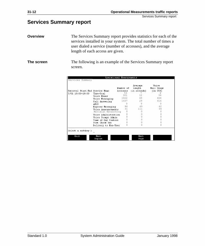
31-12 Operational Measurements traffic reports
the a
t
Services Summary report
Services Summary report
Overview The Services Summary report provides statistics for each of services installed in your system. The total number of times user dialed a service (number of accesses), and the averagelength of each access are given.
The screen The following is an example of the Services Summary reporscreen.
53 7 4 301 12 36
1022 65 664 1437 29 416 0 0 0 86 49 42 31 111 34 0 0 0 0 0 0 0 0 0 0 0 0 0 0 0 0 0 0
Services Summary
Meridian Networking
Standard 1.0 System Administration Guide January 1998
Operational Measurements traffic reports 31-13Fields in the Services Summary report
ld r of ic
the o of d en. a
d.
he
ted
ten all
in the
Fields in the Services Summary report
Interval Start-End Data are divided into intervals. The length of the interval depends on the entry made in the Traffic Commit Interval fiein the Operational Measurement Options screen. The numbeintervals displayed depends on the entries made in the TraffPeriod Start and Traffic Period End fields in the Operational Measurement Options screen.
ExampleIf data is collected 24 hours a day (from 01:00 to 01:00), and commit interval is one hour, the report will divide the data int24 intervals for each day included in the report. The amountdata displayed in this report depends on the Report Start anReport End entries that were made in the Traffic Reports screIf no report start and end dates and times were given, all datcurrently stored on disk are displayed.
Service Name This field displays the name of the service that was accesse
Number of Accesses This field displays the number of calls (peg count) made to tcorresponding service. The number of Thru-Dial accesses includes accesses to Voice Service Thru-Dial (automated attendants), Call Service Thru-Dial, and Logon Thru-Dial.
Note: If a call continues past the interval, the access is counonly in the second interval (when the call is completed), although the call length is properly divided between the twointervals.
Example 1If a call starts ten minutes before the end of an interval, that minutes of call length is counted in that interval. If the same ccontinues for five minutes into the next interval, the five minutes is counted in the second interval. The number of accesses is increased by zero in the first interval and by onethe second interval. The call is pegged in this way to match way calls are tracked by the switch.
Standard 1.0 System Administration Guide January 1998
31-14 Operational Measurements traffic reports
in
in . r not
Fields in the Services Summary report
Example 2If a call that spans two intervals is the only call to that servicethose intervals, the number of accesses in the first interval would be zero while the number of accesses in the second interval would be one.
Average Length (in seconds)
This field displays the average length of the corresponding voice service sessions during the specified interval.
Voice Mail Usage (in CCS)
This field displays the amount of time that a Meridian Mail service was active in the defined interval. The value is givenCCS (hundred call-seconds), a traffic measurement statisticOne CCS is equal to 100 seconds of call connection time pehour. The CCS is based on the total number of call seconds,the average length multiplied by the number of accesses.
Standard 1.0 System Administration Guide January 1998
Operational Measurements traffic reports 31-15Analyzing the Services Summary report
ic
hat d to
unt
at se it.
l e
o
re or ue
Analyzing the Services Summary report
Introduction Use the summary report, including the CCS values, to get anoverall sense of which services are generating the most traffand which are generating little or no traffic. Consider the example and the information that follows when doing your analysis.
ExampleThe second line in the sample report on page 31-12 shows t301 calls, with an average length of 12 seconds, were placethe Voice Menu service for a total of 3612 seconds (301 x 12). This equates to 36 CCS in the one-hour interval. The CCS cois computed for the one-hour interval as follows:
A feature is not being used
This may mean that the feature is not working properly, or ththe users are not aware of the feature and therefore do not u
Suggested actionAfter the administrator notices a low (or no) usage of a particular feature, it is up to the administrator to do additionaresearch to determine if there is a technical problem with thefeature, or if it simply is not being used, or if it is normal for thusage to be low for the observed time period.
If a particular feature is generating an unusually high amount of traffic
If a feature is generating an unusually high amount of traffic,you may encounter system performance problems such as nfree channels.
Suggested actionsRun the report that goes with that service, if there is one, formore information. As the administrator, you may need to do more research beyond checking the OM reports to learn moabout the nature of the problem to come up with a solution. Fexample, you need to determine if the high traffic level was d
100 seconds~~CCS =
3612 seconds= 36.12 36
Standard 1.0 System Administration Guide January 1998
31-16 Operational Measurements traffic reports
the
e, that s on
nd n
d for
eed
ses
Analyzing the Services Summary report
to some unusual event that affected your organization (if so, high traffic would not be expected to continue).
If the high traffic for a particular feature is expected to continuone solution may be to dedicate a channel to the feature so the feature does not tie up the whole system. For more detaildedicating channels, see Chapter 23, “Configuring Meridian Mail services”. Another solution is to expand the system if overall traffic for the whole system is higher than what was originally anticipated for the system.
Check the average length for Voice Menu and Announcement accesses
Another area to check is the average length for Voice Menu aAnnouncement accesses (see “Services Summary report” opage 31-12).
Suggested actionIf the average length is long, review your menus and announcements to see if they can be shortened or rearrangemore efficient use.
In menus, place the popular items first so that users do not nto stay on the line as long before the item they want is presented. If a menu has a long average length and it accesan announcement, try to shorten the announcement.
Standard 1.0 System Administration Guide January 1998
Operational Measurements traffic reports 31-17Analyzing the Services Summary report
g any
e
If ou
,
first ata e of
he
High number of Call Answering accesses
Suggested actionIf the number of Call Answering accesses is high, check thelogon count versus the number of times Call Answering has been accessed (the Voice Messaging Detail report gives thelogon count).
If the logon count is low compared to the number of Call Answering accesses, this means that users are accumulatinseveral messages before logging on to listen to them. Too maccumulated messages lowers the amount of available disk space to the point where overall system performance may baffected.
Users are having trouble logging in at a certain time
Suggested actionIf users are having trouble logging in to Meridian Mail at a certain time, check the level of traffic for that time period.
You may have found your heavy traffic period or busy hour. there is no way to reduce the traffic during that time period, ymay need to expand your system.
The number of Thru-Dial accesses is unusually high
If you have an unusually high number of Thru-Dial accessesthis may be a sign of hackers present on your system.
Suggested actionsIf you suspect hackers are accessing the Thru-Dial feature, check how the Thru-Dial service is set up to see if the OM dare unusual. If your research suggests the possible presenchackers, review the dialing restrictions for Thru-Dial (refer tothe Voice Services Application Guide [NTP 555-7001-325] for details). Also, if you are using an access password for Thru-Dial, change the access password and continue to monitor tThru-Dial usage.
Standard 1.0 System Administration Guide January 1998
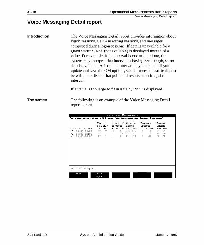
31-18 Operational Measurements traffic reports
ut
no
to
Voice Messaging Detail report
Voice Messaging Detail report
Introduction The Voice Messaging Detail report provides information abologon sessions, Call Answering sessions, and messages composed during logon sessions. If data is unavailable for agiven statistic, N/A (not available) is displayed instead of a value. For example, if the interval is one minute long, the system may interpret that interval as having zero length, so data is available. A 1-minute interval may be created if you update and save the OM options, which forces all traffic databe written to disk at that point and results in an irregular interval.
If a value is too large to fit in a field, >999 is displayed.
The screen The following is an example of the Voice Messaging Detail report screen.
18 0 2 16 238 470 0 2 20 2512 2 5 9 310 310 1 32 14 1417 1 1 17 478 614 1 20 20 20
13:00-14:0014:00-15:0015:00-16:00
Standard 1.0 System Administration Guide January 1998
Operational Measurements traffic reports 31-19Fields in the Voice Messaging Detail report
ld r of ic
d
unt and en. a
the
ss
eir
Fields in the Voice Messaging Detail report
Interval Start-End Data are divided into intervals. The length of the interval depends on the entry made in the Traffic Commit Interval fiein the Operational Measurement Options screen. The numbeintervals displayed depends on the entries made in the TraffPeriod Start and Traffic Period End fields in the Operational Measurement Options screen.
ExampleIf data are collected 24 hours a day (from 01:00 to 01:00), anthe commit interval is one hour, the report will divide the datainto 24 intervals for each day included in the report. The amoof data displayed in this report depends on the Report Start Report End entries that were made in the Traffic Reports screIf no report start and end dates and times were given, all datcurrently stored on disk are displayed.
Number of Calls (Int and Ext)
This field shows the number of Voice Messaging, Call Answering, or Express Messaging calls made. The data aredisplayed in the following subfields.
IntThis display indicates the number of calls made from inside switch during the specified interval.
ExtThis display indicates the number of calls made from outsidethe switch during the specified interval.
Number of Sessions (EM/Ans and Log)
This is the number of sessions in the interval.
EM/AnsThis display indicates the number of sessions used for ExpreMessaging and Call Answering services.
LogThis display indicates the number of time users logged into thmailboxes during the interval.
Standard 1.0 System Administration Guide January 1998
31-20 Operational Measurements traffic reports
ual e
(in
the
ated
gth
e, een
Fields in the Voice Messaging Detail report
Note: The sum of the values in these two columns should eqthe sum of the two Number of Calls values. To determine thnumber of messages that were actually received or createdduring these sessions, check the Messages Created fields.
Session Length (Avg and Max)
This field indicates the average length and maximum length seconds) of Call Answering, Express Messaging, and logon sessions for the interval.
Messages Created (EM/Ans and Log)
This field indicates the number of messages created during interval.
EM/AnsThis display indicates the number of messages left during Express Messaging and Call Answering services.
LogThis display indicates the number of messages that were cre(using the compose, forward, or reply command) during the interval.
Message Length (Avg and Max)
This field indicates the average length and the maximum len(in seconds) of messages received and created during the interval. Since message length has an impact on disk storaguse this information to determine if enough disk space has bprovisioned for voice messages.
Standard 1.0 System Administration Guide January 1998
Operational Measurements traffic reports 31-21Analyzing the Voice Messaging Detail report
18 ns wo ture
is a
the g are 0 to
ated.
ay all
is .
rs rs
Analyzing the Voice Messaging Detail report
Introduction The first line in the sample report on page 31-18 shows that calls were placed to Meridian Mail. Sixteen were logon sessio(for example, to compose, forward, or listen to messages). Tcalls accessed the Express Messaging or Call Answering fea(an attempt to leave a message at another mailbox). If the number of sessions does not equal the number of calls, thereproblem with your system.
EM/Ans Sessions and Messages are similar in number
The number of EM/Ans sessions should match or be close tonumber of EM/Ans messages created. When there are moreEM/Ans sessions than EM/Ans messages created (as in thesample report), this means that during an Express Messaginsession, or after reaching the Call Answering greeting, usershanging up without leaving a message, or they are pressing transfer to an attendant. Either of these results in Express Messaging or Call Answering sessions but no messages cre
Suggested actionsIf the disparity between the two numbers is high, the users mneed some training on the use of Express Messaging and CAnswering. Also, users should review their greetings. If greetings are unfriendly or if instructions are too complex, thmay be causing users to hang up without leaving a message
There is a high number of calls and long messages
On this report, watch for high numbers of calls and long messages. Too many calls in a short period of time and useleaving long messages will tie up channels and prevent othefrom accessing Meridian Mail.
Suggested actionYou may need to expand your system.
Standard 1.0 System Administration Guide January 1998
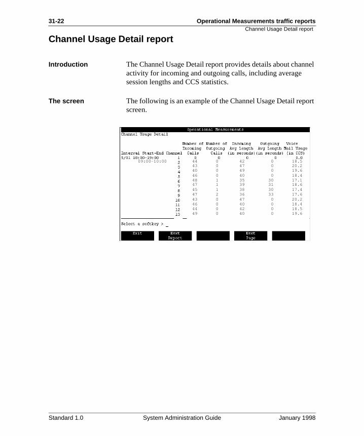
31-22 Operational Measurements traffic reports
nel
ort
Channel Usage Detail report
Channel Usage Detail report
Introduction The Channel Usage Detail report provides details about chanactivity for incoming and outgoing calls, including average session lengths and CCS statistics.
The screen The following is an example of the Channel Usage Detail repscreen.
44 0 42 0 18.5 43 0 47 0 20.2 40 0 49 0 19.6 46 0 40 0 18.4 48 1 35 30 17.1 47 1 39 31 18.6 45 1 38 30 17.4 47 2 36 33 17.6 43 0 47 0 20.2 46 0 40 0 18.4 44 0 42 0 18.5 49 0 40 0 19.6
09:00-10:00
Standard 1.0 System Administration Guide January 1998
Operational Measurements traffic reports 31-23Fields in the Channel Usage Detail report
ld r of ic
d
unt and en. a
ng
g
t a S e
s
Fields in the Channel Usage Detail report
Interval Start-End Data are divided into intervals. The length of the interval depends on the entry made in the Traffic Commit Interval fiein the Operational Measurement Options screen. The numbeintervals displayed depends on the entries made in the TraffPeriod Start and Traffic Period End fields in the Operational Measurement Options screen.
ExampleIf data are collected 24 hours a day (from 01:00 to 01:00), anthe commit interval is one hour, the report will divide the datainto 24 intervals for each day included in the report. The amoof data displayed in this report depends on the Report Start Report End entries that were made in the Traffic Reports screIf no report start and end dates and times were given, all datcurrently stored on disk are displayed.
Channel This field indicates the channel being monitored.
Number of Incoming Calls
This field indicates the number of incoming calls during the interval.
Number of Outgoing Calls
This field indicates the number of outgoing calls during the interval.
Incoming Avg Length (in seconds)
This field indicates the average length of incoming calls durithe interval.
Outgoing Avg Length (in seconds)
This field indicates the average length of outgoing calls durinthe interval.
Voice Mail Usage (in CCS)
This field represents the amount of time in terms of CCS thaMeridian Mail channel was active in the defined interval. CCis a traffic measurement statistic. The value is displayed in thnearest one tenth of a CCS (for example, 11.0).
Note: There is a similar Voice Mail Usage field in the ServiceSummary Traffic report (see “Services Summary report” on
Standard 1.0 System Administration Guide January 1998
31-24 Operational Measurements traffic reports
ge of
.
Fields in the Channel Usage Detail report
page 31-12). However, because the two fields measure usadifferently (one in terms of channels and the other in terms voice services), there may be small differences between thetwo fields if you calculate the totals for the displayed values
Standard 1.0 System Administration Guide January 1998
Operational Measurements traffic reports 31-25Analyzing the Channel Usage Detail report
ach
unt
re of the
le,
ing sy ing
Analyzing the Channel Usage Detail report
Introduction The CCS for each channel gives an indication of how busy echannel is. With Automated Call Distribution (ACD), the traffic(measured in CCS) should be evenly distributed across all channels over a lengthy period (for example, 12 hours).
Equal distribution of channel traffic
Channels with short durations will have a higher number of calls than channels with long durations, but the average amoof traffic (for example, CCS) for each nondedicated channel should be similar.
Suggested actionIf the traffic is not evenly distributed, check if all channels areworking properly. If a channel has no traffic at all for the entiperiod of the report, this may indicate that the channel is outservice. If any channels are dedicated to a particular service,number of calls for the dedicated channels may differ significantly from the number of calls on the other channels.
Users are having trouble accessing Meridian Mail
Users may have trouble accessing Meridian Mail (for exampcallers are getting ringback or a busy signal) if the system isbusy.
Suggested actionCheck if the dedicated channel appears to have much fewercalls than other channels. If so, you may be better off removthe dedication and opening the channel to all services. A busystem cannot afford to have any channels that are not sharthe full load on the system.
Standard 1.0 System Administration Guide January 1998
31-26 Operational Measurements traffic reports
or il
me-en r enu
Services Detail report
Services Detail report
Introduction This report is available only if Fax on Demand, Voice Forms,Voice Menus is installed on your system. The Services Detareport records the number of accesses, direct or indirect, to voice menus, announcements, fax items, thru-dial service, tiof-day controllers, and voice forms. Direct accesses occur wha user dials the VSDN of the service. Indirect accesses occuwhen a service is accessed from another service through a mselection.
The screen The following is an example of the Services Detail report screen.
ASMSFI MSMSMSMSVFTDTS
1003101130014022402340334058101310231033
11 0 0 0 0 0 0 0 0 0 0 0 0 2 0 0 0 0 0 0 0 0 0 0 0 0 2 0 0 0 0 0 0 0 0 0 0 0 0 2 1 0 0 1 0 0 0 0 0 0 0 0 5 0 0 1 0 0 1 0 2 0 0 0 042 6 21 0 0 0 0 0 0 0 0 0 0 41 116 0 6 4 0 0 0 0 1 2 0 1 - - - - - - - - - 0 - - 2 - - - - - - - - - - - - 1 - - - - - - - - - 0 - -
167
09:00-10:00
Standard 1.0 System Administration Guide January 1998
Operational Measurements traffic reports 31-27Fields in the Services Detail report
r of ic
is
d in ies rt on
re
r
enu, the
Fields in the Services Detail report
Interval Start-End Data are divided into intervals. The length of the interval depends on the entry made in the Traffic Commit Interval field in the Operational Measurement Options screen. The numbeintervals displayed depends on the entries made in the TraffPeriod Start and Traffic Period End fields in the Operational Measurement Options screen.
Example
If data are collected 24 hours a day, and the commit intervalone hour, the report will divide the data into 24 intervals for each day included in the report. The amount of data displayethis report depends on the Report Start and Report End entrthat were made in the Traffic Reports screen. If no report staand end dates and times were given, all data currently storeddisk are displayed.
ID This is the service followed by the ID number. The services aas follows.
Service Accesses This is the number of times the service was accessed (eithedirectly or indirectly) during the measurement period.
For each menu item, the number of accesses are
This is the total number of times that each menu option wasused during the measurement period. For stand-alone announcements and fax items, all frequencies are 0. If announcements or fax items are accessed through a voice mthen there is an access count if a caller presses 0 to revert toattendant.
Acronym Service Acronym Service
AS Announcement VF Voice Forms
MS Voice Menu TD Time of Day
FI Fax Information TS Thru-Dial
Standard 1.0 System Administration Guide January 1998
31-28 Operational Measurements traffic reports
lf
ly mn
ey the re
Fields in the Services Detail report
Note: The number of accesses for the individual menu itemsmay not add up to the number of accesses for the menu itse(Service Accesses) because some callers will hang up afterreaching the menu if they do not want to choose any of the menu options, or if they want to talk to a live person.
Similarly, calls from rotary dial phones that are able to directaccess a menu will be counted in the Service Accesses colubut not in the number of accesses for individual menu items,since the rotary dial phone does not have the touch-tone capability required to select a menu item.
For Thru-Dial and Voice Forms, the number of accesses for k“0” count the number of times callers press zero to revert to attendant. The “-” (dashes) emphasize no other count keys abeing counted. For Time of Day, all menu item accesses areshown as dashes.
Standard 1.0 System Administration Guide January 1998
Operational Measurements traffic reports 31-29Analyzing the Services Detail report
sed,
of
8
ms
the ing
to
f the
ts
ither
Analyzing the Services Detail report
Introduction This report provides a detailed breakdown of which menu items, announcements, or fax items are actually being accesand a sense of the traffic that each service is generating.
Note: For a proper analysis of this report, have a printed copythe service in front of you for reference.
While reviewing the report, consider the following.
If the menu requires reorganization
Menu items that are at the end of the menu (for example, itemor 9) are being accessed more frequently than earlier items.
Suggested actionYou may wish to reorganize the menu so that the popular iteare presented first.
This structure prevents users from having to wait through all earlier options before hearing the one they want, thus reducthe call length.
A service is generating a high volume of traffic
A particular service is generating a high volume of traffic.
Suggested actionFind out if there is any call blockage (that is, users are unableaccess the system).
If announcements or menus are causing call blockage, see iinformation can be provided in some other way than throughMeridian Mail (for example, through hard-copy memos or bulletin boards). If the service is a definite requirement and iusage cannot be decreased, then your system may require achannel expansion.
There are menu items with few or no accesses
If a menu item has few or no accesses, the reason may be ethat there is a lack of training or awareness regarding those items, or that those items are simply not required.
Standard 1.0 System Administration Guide January 1998
31-30 Operational Measurements traffic reports
ve the as
e
son
Analyzing the Services Detail report
Suggested actionIf you find that certain services are not required, either remothem or replace them with more useful services. Check with application owners to ensure the correct telephone number hbeen provided to the target audience. Be sure to rerecord thgreetings and menu choices to reflect the changes.
The traffic pattern is unusual
Is the traffic high or low for a particular service?
Suggested actionConsult the users to determine if there was some unusual reafor the change in traffic.
If the high or low traffic is expected to return to acceptable levels, no adjustment may be necessary to the system.
Standard 1.0 System Administration Guide January 1998
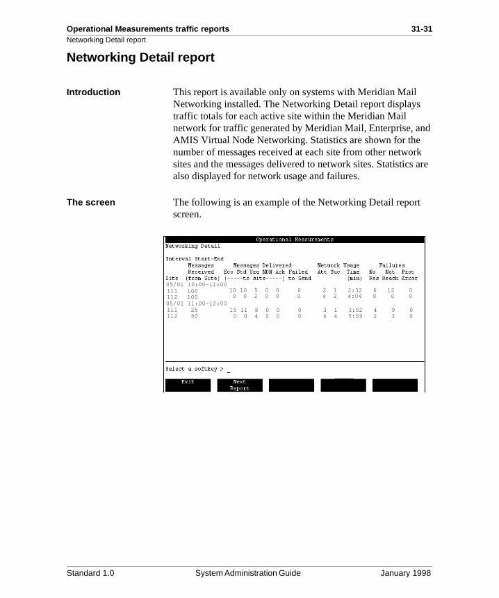
Operational Measurements traffic reports 31-31Networking Detail report
d
rk are
Networking Detail report
Introduction This report is available only on systems with Meridian Mail Networking installed. The Networking Detail report displays traffic totals for each active site within the Meridian Mail network for traffic generated by Meridian Mail, Enterprise, anAMIS Virtual Node Networking. Statistics are shown for the number of messages received at each site from other netwosites and the messages delivered to network sites. Statisticsalso displayed for network usage and failures.
The screen The following is an example of the Networking Detail report screen.
10 10 5 0 0 0 2 1 2:32 6 12 0 0 0 2 0 0 0 4 2 4:04 0 0 0
05/01 10:00-11:00111 100112 10005/01 11:00-12:00111 25112 50
15 11 8 0 0 0 3 1 3:02 4 9 0 0 0 4 0 0 0 6 4 5:09 2 3 0
Standard 1.0 System Administration Guide January 1998
31-32 Operational Measurements traffic reports
ld r of ic
ne his hat d
disk
to
Fields in the Networking Detail report
Fields in the Networking Detail report
Interval Start-End Data are divided into intervals. The length of the interval depends on the entry made in the Traffic Commit Interval fiein the Operational Measurement Options screen. The numbeintervals displayed depends on the entries made in the TraffPeriod Start and Traffic Period End fields in the Operational Measurement Options screen.
Example If data is collected 24 hours a day and the commit interval is ohour, the report will divide the data into 24 intervals for eachday included in the report. The amount of data displayed in treport depends on the Report Start and Report End entries twere made in the Traffic Reports screen. If no report start anend dates and times were given, all data currently stored on are displayed.
Site This is the remote site ID to which the row of data applies.
Messages Received This field indicates the number of messages received successfully by the local site from the specified remote site.
Messages Delivered This is the number of messages delivered from the local sitethe identified remote site during the specified interval. This statistic is further subdivided into the following categories based on the type of message.
EcoThese are messages that have been classed as economy.
StdThese are messages that have been classed as standard.
UrgThese are messages that have been classed as urgent.
Standard 1.0 System Administration Guide January 1998
Operational Measurements traffic reports 31-33Fields in the Networking Detail report
tem the
ate read
ed
d ery to
by s.
ed,
and ted r
NDNThese are non-delivery notification messages sent by the systo users whose messages could not be delivered to some ofintended recipients due to incorrect addressing.
AckThese are acknowledgments sent to the remote site to indicthat a message (that was tagged for acknowledgment) was by the Meridian Mail user at the local site.
Failed to sendThis indicates messages for which each delivery attempt failand the messages could not be delivered to the remote site within the stale time threshold (refer to the Meridian Networking Installation and Administration Guide [NTP 555-7001-244] for information about stale-dating). Faileto Send messages are returned to the user with a Non-DelivNotification (NDN). The user then may forward the messagethe remote user again.
Network Usage This statistic indicates the number of networking calls placedthe local site to the specified remote site during the specifiedinterval. It is further broken down into the following categorie
AttThis indicates the number of attempted calls. For outgoing sessions, this field is incremented each time a channel is acquired to make a call to this remote site (for Meridian Networking, a modem is also successfully allocated). For incoming sessions, it is incremented when the call is answerand the network passwords and site IDs are confirmed.
Note: Virtual Node AMIS does not use network passwords.
SucThis indicates the number of successful calls. For Meridian Networking outgoing connections, it is incremented when thecall is placed to this remote site and the network passwords site IDs are confirmed. For incoming sessions, it is incremenprovided the maximum number of ports is not exceeded. FoVirtual Node AMIS or Enterprise sessions, it is incremented
Standard 1.0 System Administration Guide January 1998
31-34 Operational Measurements traffic reports
the ot
ing
Fields in the Networking Detail report
once for each session in which at least one message is successfully sent or received.
Time (min)This indicates the total amount of time (in minutes) used by networking calls to and from the specified remote site.
Failures A failure refers to a single unsuccessful attempt to send a networking message. Networking will attempt to send these messages the next time it is scheduled to send messages toremote site. If a message experiences many failures and is ndelivered within a certain period of time, it will be reported inthe Failed to Send field and the message is returned to the sender.
No ResThe No Resources failure means that one of the following occurred:
• no channels available
• maximum number of outgoing connections is reached
• if Meridian Networking, there were no modems available
Not Reach This field is incremented each time a network connection is dropped or a problem is encountered while sending or receivmessage information.
Prot ErrorThis field is incremented if a protocol violation is detected.
Standard 1.0 System Administration Guide January 1998
Operational Measurements traffic reports 31-35Analyzing the Networking Detail report
e
the
y
e g
due
lass
Analyzing the Networking Detail report
Introduction This report provides a detailed breakdown of the networkingusage on the system. While viewing the reports, consider thfollowing information.
Note: For a proper analysis of this report, have a diagram of network in front of you to refer to.
High number of “Failed to Send” messages
If the number of “Failed to Send” messages is high, there mabe a problem with your networking setup.
Suggested actionCheck to make sure that the remote site is not down. If the remote site is up and running, check the networking schedulparameters to see if they are correct. For details on changinnetworking parameters, refer to one of the following documents:
• Meridian Networking Installation and Administration Guide (NTP 555-7001-244)
• Virtual Node AMIS Networking Installation and Administration Guide (NTP 555-7001-245)
• Enterprise Networking Installation and Administration Guide (NTP 555-7001-246)
The number of NDNs delivered is high
If the number of NDNs delivered is high, this indicates that messages couldn’t be delivered to local users. This may be to one of the following:
The local users do not exist, the address in the message is incorrect, or the user cannot receive composed messages (Cof Service field):
• The local systems disk is full.
• The network setup is incorrect.
- Site numbers and location IDs are defined differentlyfrom remote sites.
- Mailbox number/dial plan is configured incorrectly.
Standard 1.0 System Administration Guide January 1998
31-36 Operational Measurements traffic reports
m ork the
may
s,
Analyzing the Networking Detail report
Suggested actionCheck that the disk is not full. If that is not the problem, confirthat the network setup is the same as the remote site’s netwdatabase. If this is not the problem, confirm the existence of remote site which the mailboxes cannot be delivered to and confirm that the site can receive composed messages.
The ratio of urgent networking messages to others sent is high
If the number of urgent networking messages sent is high compared to the number of standard messages, the systemnot have enough channels or modems (Meridian Mail Networking only) to support the actual traffic.
Suggested actionIf this is a problem, you may want to change the networking configuration. For details on changing networking parameterrefer to one of the following documents:
• Meridian Networking Installation and Administration Guide (NTP 555-7001-244)
• Virtual Node AMIS Networking Installation and Administration Guide (NTP 555-7001-245)
• Enterprise Networking Installation and Administration Guide (NTP 555-7001-246)
Standard 1.0 System Administration Guide January 1998
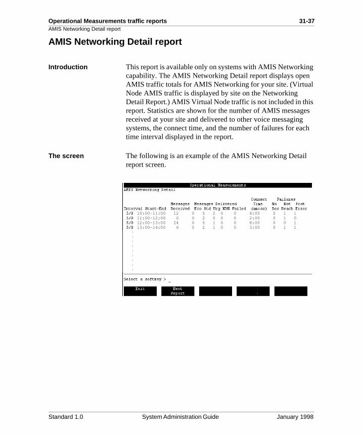
Operational Measurements traffic reports 31-37AMIS Networking Detail report
g
es ch
AMIS Networking Detail report
Introduction This report is available only on systems with AMIS Networkincapability. The AMIS Networking Detail report displays openAMIS traffic totals for AMIS Networking for your site. (Virtual Node AMIS traffic is displayed by site on the Networking Detail Report.) AMIS Virtual Node traffic is not included in thisreport. Statistics are shown for the number of AMIS messagreceived at your site and delivered to other voice messagingsystems, the connect time, and the number of failures for eatime interval displayed in the report.
The screen The following is an example of the AMIS Networking Detail report screen.
10:00-11:00 12 0 5 2 0 0 4:00 0 1 111:00-12:00 0 0 2 0 0 0 2:00 0 1 012:00-13:00 24 0 5 1 0 0 8:00 0 0 113:00-14:00 6 0 2 1 0 0 3:00 0 1 1
Standard 1.0 System Administration Guide January 1998
31-38 Operational Measurements traffic reports
ld r of ic
d
unt and en. a
g ing
, that ng
, that ng
at ng
Fields in the AMIS Networking Detail report
Fields in the AMIS Networking Detail report
Interval Start-End Data are divided into intervals. The length of the interval depends on the entry made in the Traffic Commit Interval fiein the Operational Measurement Options screen. The numbeintervals displayed depends on the entries made in the TraffPeriod Start and Traffic Period End fields in the Operational Measurement Options screen.
ExampleIf data are collected 24 hours a day (from 01:00 to 01:00), anthe commit interval is one hour, the report will divide the datainto 24 intervals for each day included in the report. The amoof data displayed in this report depends on the Report Start Report End entries that were made in the Traffic Reports screIf no report start and end dates and times were given, all datcurrently stored on disk are displayed.
Messages Received This field indicates the number of AMIS messages that werereceived at the local site during the time interval indicated.
Messages Delivered This field indicates the number of AMIS messages (originatinfrom the local site) that were delivered to other voice messagsystems during the interval indicated. This statistic is furthersubdivided according to the type of message.
EcoThis indicates the number of messages, tagged as economywere delivered to other AMIS voice messaging systems durithe specified interval.
StdThis indicates the number of messages, tagged as standardwere delivered to other AMIS voice messaging systems durithe specified interval.
UrgThis indicates the number of messages, tagged as urgent, thwere delivered to other AMIS voice messaging systems durithe specified interval.
Standard 1.0 System Administration Guide January 1998
Operational Measurements traffic reports 31-39Fields in the AMIS Networking Detail report
al es ite.
not
ages the
nd
e to
be
ing
de d
NDNThese are nondelivery notification messages sent by the locsystem to users at other messaging systems whose messagcould not be delivered to the intended recipient at the local sMessages may not be delivered for the following reasons:
• The address is incorrect (for example, the mailbox does exist).
• The user does not have the ability to receive AMIS messages (Class of Service field).
• The disk is full.
• A system error occurred.
FailedThis indicates the number of unsent messages. These messexperienced a series of failures and could not be sent beforestale period.
Connect Time (mm:ss) This number indicates the total amount of time (in minutes aseconds) used by AMIS Networking calls during the time interval indicated.
Failures This indicates the number of AMIS messages that were not successfully delivered to other AMIS messaging systems duspecific problems. This statistic is further subdivided into thetypes of problems that may prevent messages from being delivered.
No ResThe No Resources failure means that a voice port could not accessed to send these messages to another AMIS site.
Not ReachThis field is incremented each time a network connection is dropped or a problem is encountered while sending or receivmessage information.
Prot ErrorThe Protocol Error failure means that the connection was mato the remote AMIS site, but message delivery was preventeby a protocol error.
Standard 1.0 System Administration Guide January 1998
31-40 Operational Measurements traffic reports
en ion ages
may
Analyzing the AMIS Networking Detail report
Analyzing the AMIS Networking Detail report
Introduction This report provides a detailed breakdown of the AMIS Networking usage on the system. While viewing the reports,consider the following information.
The number of NDNs delivered or the number of “Failed to Send” messages is high
If the number of NDNs delivered or the number of “Failed to Send” messages is high, there may be a problem with your networking setup or the switch/telephone network. Since OpAMIS requires the user to enter the DN to dial at the destinatmessaging system, it may be that users are addressing messincorrectly.
Also, if the failed to send is high, check the “Number Of Messages To Transmit Per Session” field. Try setting it to a higher number, for example, nine. (Also, make sure a billingDN is defined.)
Suggested actionRefer to the AMIS Networking Installation and Administration Guide (NTP 555-7001-242) for details on the proper setup ofthe networking feature.
The ratio of urgent networking messages to others sent is high
If the number of urgent networking messages sent is high compared to the number of standard messages, the systemnot have enough channels to support the actual traffic.
Suggested actionIf this is a problem, you may want to change the networking configuration in the Networking Call Maximum field. Refer tothe AMIS Networking Installation and Administration Guide (NTP 555-7001-242) for details on changing networking parameters.
Standard 1.0 System Administration Guide January 1998
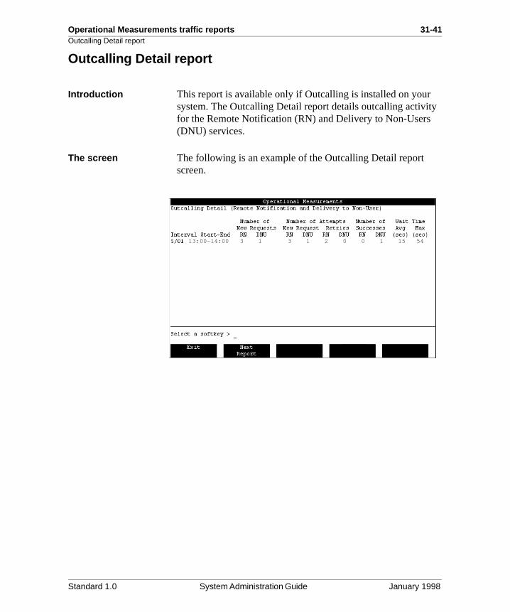
Operational Measurements traffic reports 31-41Outcalling Detail report
y
Outcalling Detail report
Introduction This report is available only if Outcalling is installed on your system. The Outcalling Detail report details outcalling activitfor the Remote Notification (RN) and Delivery to Non-Users (DNU) services.
The screen The following is an example of the Outcalling Detail report screen.
13:00-14:00 3 1 3 1 2 0 0 1 15 54
Standard 1.0 System Administration Guide January 1998
31-42 Operational Measurements traffic reports
ld r of ic
d
unt and en. a
re
en
up
Fields in the Outcalling Detail report
Fields in the Outcalling Detail report
Interval Start-End Data are divided into intervals. The length of the interval depends on the entry made in the Traffic Commit Interval fiein the Operational Measurement Options screen. The numbeintervals displayed depends on the entries made in the TraffPeriod Start and Traffic Period End fields in the Operational Measurement Options screen.
ExampleIf data are collected 24 hours a day (from 01:00 to 01:00), anthe commit interval is one hour, the report will divide the datainto 24 intervals for each day included in the report. The amoof data displayed in this report depends on the Report Start Report End entries that were made in the Traffic Reports screIf no report start and end dates and times were given, all datcurrently stored on disk are displayed.
Number of New Requests
This field indicates the total number of new requests that wemade for outcalling services during the interval.
RNThis indicates the number of new requests for the Remote Notification service.
DNUThis indicates the number of new requests for the Delivery toNon-User service.
Number of Attempts This indicates the total number of Remote Notification and Delivery to Non-User attempts made during the interval.
New RequestThis number represents the number of attempts that have bemade to answer the new requests for RN and DNU. If the Number of Attempts does not equal the Number of New Requests (see the previous field), the system is not keepingwith outcalling requests and more channels may need to be allocated to outcalling.
Standard 1.0 System Administration Guide January 1998
Operational Measurements traffic reports 31-43Fields in the Outcalling Detail report
e n
rred
to
e
e
r of N g
rs
RetriesThis number represents the number of times that the RemotNotification and Delivery to Non-Users services have retriedcalls because one of the following occurred at the destinationumber.
Number of Successes This indicates the number of successful remote notificationsand messages successfully delivered to non-users that occuduring the interval.
RNRN successes are measured in terms of user login. In other words, an RN call is considered successful if the user logs inhis or her mailbox when the notification is received (on the same call as the notification). If the user receives the notification, hangs up, and then logs in to his or her mailbox,this is not counted as a success since the user terminated thnotification call without logging in.
Note: For remote notification to a pager, RN calls are never counted as successful in reports because the paging serviccannot log in to the mailbox. A better measure of the effectiveness of RN calls to pagers is to compare the numbeRN retries to RN attempts. However, bear in mind that an Rretry does not necessarily mean the RN attempt to the paginservice failed; it only signifies that the user did not log on within the retry interval.
DNUA DNU call is considered successful if the called party answethe call (and DTMF confirmation is given if required).
Event at Destination Number Service Affected
the number was busy RN and DNU
there was no answer RN and DNU
the phone or pager service answered but no logon occurred
RN
the required DTMF confirmation was not given
DNU
Standard 1.0 System Administration Guide January 1998
31-44 Operational Measurements traffic reports
ed
ll.
o
Fields in the Outcalling Detail report
Wait Time These values are an indication of how long it takes for the outcalling agent to acquire a channel to outcall to the specifidirectory number (DN).
Avg (sec)This is the average amount of time, based on all outcalling attempts made during the interval, that it took the outcalling agent to acquire the resources necessary to make the outca
Max (sec)This number represents the outcalling attempt that took the longest amount of time to acquire the resources necessary tmake the outcall.
Standard 1.0 System Administration Guide January 1998
Operational Measurements traffic reports 31-45Analyzing the Outcalling Detail report
g
ho
log
ot ere g
or
Analyzing the Outcalling Detail report
Low usage of Outcalling features
The sample report may indicate minimal use of the Outcallinfeatures. The following reasons may help explain why.
Users do not know how to use the service If so, train all outcalling users on how to use the service.
Users are unaware that the service existsIf so, inform the users of the service and provide training if necessary.
Users do not need to use the serviceConsult the users to determine if they really do not need theservice. Delete the service from the mailbox of those users wconfirm that they do not need the outcalling service.
Technical problem with the serviceHave the problem investigated and fixed.
The number of retries is high
If the number of retries is high, the reason may be one of thefollowing:
• The destination number was busy.
• There was no answer at the destination.
• The user at the destination answered the call but did not in.
Users are not retrieving messages
If users are consistently not retrieving messages, they may nbe aware of how to properly use the outcalling service; or thcould be a technical problem preventing users from retrievinthe messages.
Suggested actionConsult the users to find out if the problem is with the systemwith the users.
Standard 1.0 System Administration Guide January 1998
31-46 Operational Measurements traffic reports
er t not
by g
g
pts. the
er.
e
by
e is
the
Analyzing the Outcalling Detail report
New attempts and new requests are unequal
The number of new attempts should roughly equal the numbof new requests. If the number of new requests is somewhagreater than the number of new attempts, then the system iskeeping up with the demand for outcalling RN or DNU.
Suggested actionThe system may need more channels. Increase the limit set“Maximum Number of Outcalling Channels” on the OutcallinAdministration screen to allow more channels to be used foroutcalls.
The wait time is high The wait time indicates how long the outcalling agent has towait for a free channel. If the wait time is high, this also indicates a need for more channels. Increase the limit set by“Maximum Number of Outcalling Channels” on the OutcallinAdministration screen to allow more channels to be used foroutcalls.
The number of attempts and successes are not equal
The number of successes should equal the number of attemIf the numbers are not equal, then the reason may be one offollowing:
• There may be a problem with the destination phone/pag
• Although Meridian Mail may not have any outcalling restrictions, the switch might. For example, long distancdialing may be restricted.
• The Outcalling feature may have been set up incorrectlyeither the administrator or the user.
• If the channels were tied up for a long time, the retry timouts may have expired. If the wait times are high, then this probably what happened.
Suggested actionYou may need to dedicate channels to outcalling or increasenumber of channels dedicated to outcalling.
Standard 1.0 System Administration Guide January 1998
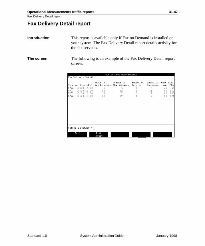
Operational Measurements traffic reports 31-47Fax Delivery Detail report
r
t
Fax Delivery Detail report
Introduction This report is available only if Fax on Demand is installed onyour system. The Fax Delivery Detail report details activity fothe fax services.
The screen The following is an example of the Fax Delivery Detail reporscreen.
13:00-14:0014:00-15:0015:00-16:0016:00-17:00
5 5 2 5 60 90 12 12 5 11 66 112 7 7 3 7 62 100 10 10 5 9 65 105
Standard 1.0 System Administration Guide January 1998
31-48 Operational Measurements traffic reports
ld r of ic
d
unt and en. a
ade
e
e.
the
to
Fields in the Fax Delivery Detail report
Fields in the Fax Delivery Detail report
Interval Start-End Data are divided into intervals. The length of the interval depends on the entry made in the Traffic Commit Interval fiein the Operational Measurement Options screen. The numbeintervals displayed depends on the entries made in the TraffPeriod Start and Traffic Period End fields in the Operational Measurement Options screen.
ExampleIf data are collected 24 hours a day (from 01:00 to 01:00), anthe commit interval is one hour, the report will divide the datainto 24 intervals for each day included in the report. The amoof data displayed in this report depends on the Report Start Report End entries that were made in the Traffic Reports screIf no report start and end dates and times were given, all datcurrently stored on disk are displayed.
Number of New Requests
This indicates the total number of new requests that were mfor the fax callback services during the interval.
Number of New Attempts
This indicates the number of attempts made to process newrequests for fax callback services during the interval.
Number of Retries This indicates the number of attempts made to process old requests for fax callback services during the interval becausone of the following occurred during the call:
• No carrier was received from the destination fax machin
• Transmission errors occurred.
Number of Successes This indicates the number of successful fax callbacks during interval.
Wait Time AvgThis indicates the average amount of time, based on all fax callback attempts made during the interval, that the fax outcalling agent needed to acquire the resources necessarymake the call.
Standard 1.0 System Administration Guide January 1998
Operational Measurements traffic reports 31-49Fields in the Fax Delivery Detail report
e
MaxThis number represents the fax callback attempt that took thlongest amount of time during the interval to acquire the resources necessary to make the call.Standard 1.0 System Administration Guide January 1998
31-50 Operational Measurements traffic reports
ut
w
ith
pts. the
e
Analyzing the Fax Delivery Detail report
Analyzing the Fax Delivery Detail report
There is minimal use of fax outcalling
There could be several reasons for minimal use of the Fax Outcalling features.
Users do not know how to use the serviceIf so, train all fax callback users on how to use the service.
Users are unaware that the service existsIf so, inform the users of the service and provide training if necessary.
Technical problem with the service Have the problem investigated and fixed.
The number of retries is high
If the number of retries is high, the reason may be one of thefollowing:
• The destination number was busy or the machine was oof paper.
• There was no answer at the destination.
• A transmit error prevented the fax from being received.
The number of new attempts should equal the number of nerequests. If the number of new requests is greater than the number of new attempts, then the system is not keeping up wthe demand for fax outcalling. The system may need more multimedia channels.
If the wait time is high, this also indicates a need for more channels. The wait time indicates how long the fax outcallingagent has to wait for a free channel.
The number of successes do not equal the number of attempts
The number of successes should equal the number of attemIf the numbers are not equal, then the reason may be one offollowing:
• There may be a problem with the destination fax device.
• Although Meridian Mail may not have any outcalling restrictions, the switch might. For example, long distancdialing may be restricted.
Standard 1.0 System Administration Guide January 1998
Operational Measurements traffic reports 31-51Analyzing the Fax Delivery Detail report
tly
e-is
he
• The fax outcalling feature may have been set up incorrecby either the administrator or the user.
• If the channels were tied up for a long time, the retry timouts may have expired. If the wait times are high, then this probably what happened. You may need to dedicate channels to fax outcalling or increase the number of channels dedicated to fax outcalling.
The wait time is high If the wait times are too long for the desired service levels, increase the Maximum Number of Fax Delivery Channels onthe Fax Administration screen and add multimedia ports to tsystem.
Standard 1.0 System Administration Guide January 1998
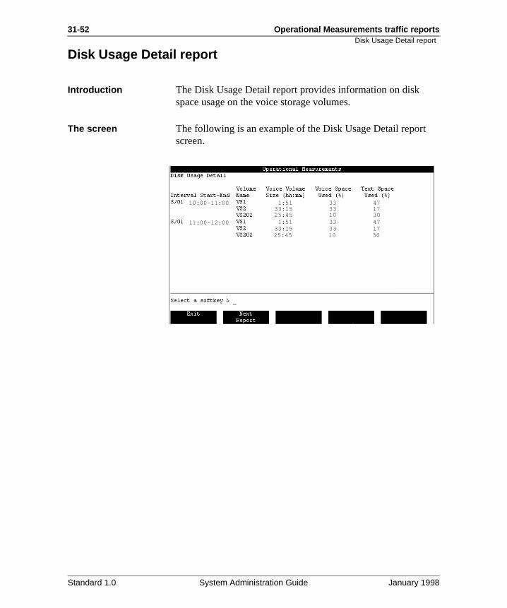
31-52 Operational Measurements traffic reports
Disk Usage Detail reportDisk Usage Detail report
Introduction The Disk Usage Detail report provides information on disk space usage on the voice storage volumes.
The screen The following is an example of the Disk Usage Detail report screen.
10:00-11:00
11:00-12:00
12:00-13:00
1:51 33 4733:15 33 1725:45 10 30 1:51 33 4733:15 33 1725:45 10 30
Standard 1.0 System Administration Guide January 1998
Operational Measurements traffic reports 31-53Fields in the Disk Usage Detail report
ld r of ic
d
unt and en. a
ter
sed
Fields in the Disk Usage Detail report
Interval Start-End Data are divided into intervals. The length of the interval depends on the entry made in the Traffic Commit Interval fiein the Operational Measurement Options screen. The numbeintervals displayed depends on the entries made in the TraffPeriod Start and Traffic Period End fields in the Operational Measurement Options screen.
ExampleIf data are collected 24 hours a day (from 01:00 to 01:00), anthe commit interval is one hour, the report will divide the datainto 24 intervals for each day included in the report. The amoof data displayed in this report depends on the Report Start Report End entries that were made in the Traffic Reports screIf no report start and end dates and times were given, all datcurrently stored on disk are displayed.
Volume Name This shows the name of the user volume (for example, VS1,VS2, VS202, VS203, and so on). Volumes are sections on Meridian Mail disks. For more information, see “Distributing local voice users evenly over volumes” on page 7-19 of Chap7, “User administration—an overview.”
Voice Volume Size (hh:mm)
This shows the amount of disk space that has been used, displayed in hours and minutes. One hour of voice storage isequivalent to 8.5 Mbytes.
Voice Space Used (%) This indicates the percentage of the volume’s voice capacityused at the end of the interval.
Text Space Used (%) This indicates the percentage of the volume’s text capacity uat the end of the interval.
Standard 1.0 System Administration Guide January 1998
31-54 Operational Measurements traffic reports
y en
ry If ists, on
ce. e
Analyzing the Disk Usage Detail report
Analyzing the Disk Usage Detail report
Voice space The voice space used will fluctuate, especially if your systemhas an automatic read-message deletion feature enabled. However, if the Voice Space Used percentage is consistentlover your disk usage warning level, then steps should be takto reduce the amount of voice space used.
Reducing voice space You can reduce the voice space used by deleting unnecessamailboxes and ensuring that distribution lists are up to date. these unnecessary or unused mailboxes are on distribution lthey may be storing messages sent using outdated distributilists. With no one logging on to delete the messages, the messages continue to accumulate and use up more disk spaYou can also encourage users to delete their messages morfrequently, or even reduce the allowable maximum messagelength (see Chapter 26, “Class of Service administration”).
ATTENTION
If the system generates a SEER 1103, print this Disk Usage Detail report immediately. This SEER indicates that your system has reached physical or virtual capacity.Check that the nightly audit is functioning. Remove files on the volume in question. If the operation involved VS1, remove directory entries or OM files. The effect of corrective actions may be delayed until the nightly audit is run. Consider redistributing users on multiple nodes, turning on automatic message deletion, or buying a storage upgrade.
Standard 1.0 System Administration Guide January 1998
Operational Measurements traffic reports 31-55Analyzing the Disk Usage Detail report
r be
ser
rs, ace
,
Reviewing voice menus, forms, and announcementsTo lower voice space used, you can also review all voice menus, voice forms, and voice announcements to see if theisize can be reduced. For example, unused menu items can removed. You can also consult the User Usage reports to identify users with excessive storage. This might happen if auser stops accessing his or her mailbox (for example, if the uis on vacation), but callers continue to leave messages.
Are the storage volumes evenly balanced?If voice space used is high on some volumes but low on otheyou may need to move high-usage subscribers to low-usagevolumes in order to balance system resources. If the voice spused on all volumes is high, you may need to expand your system.
The text space has changed dramatically
Text space used should not fluctuate greatly from day to dayalthough it will vary over time. Any large fluctuations or significant steady increases in the text space used should bereported to your technical support organization.
Standard 1.0 System Administration Guide January 1998
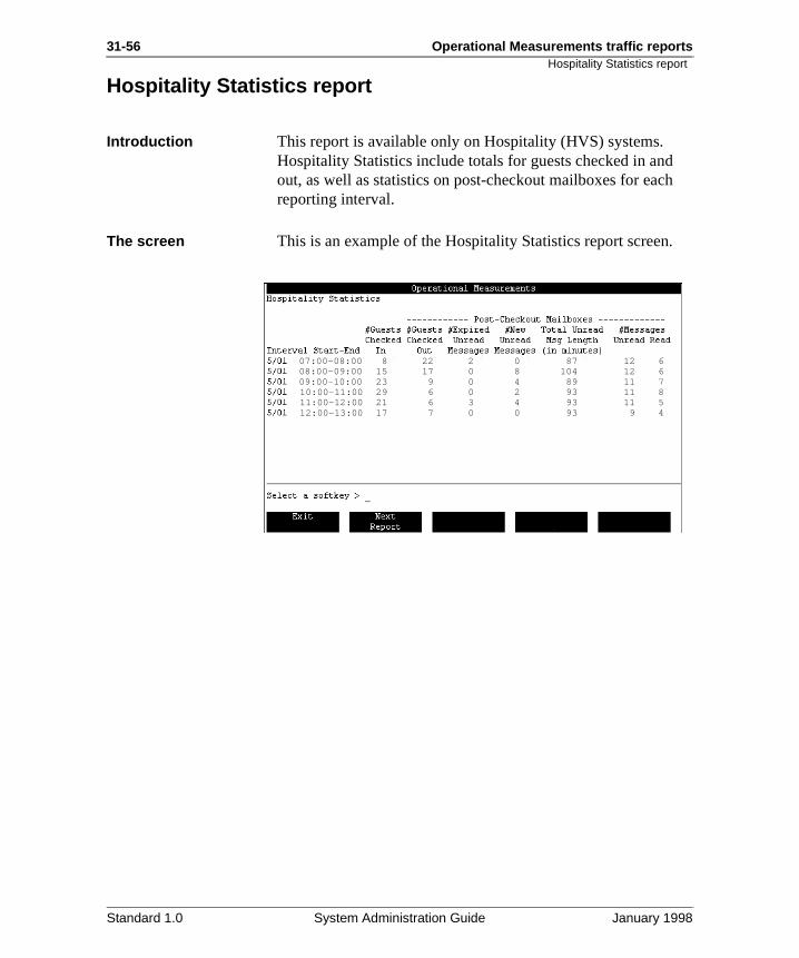
31-56 Operational Measurements traffic reports
h
.
Hospitality Statistics report
Hospitality Statistics report
Introduction This report is available only on Hospitality (HVS) systems. Hospitality Statistics include totals for guests checked in andout, as well as statistics on post-checkout mailboxes for eacreporting interval.
The screen This is an example of the Hospitality Statistics report screen
07:00-08:0008:00-09:0009:00-10:0010:00-11:0011:00-12:0012:00-13:00
8 22 2 0 87 12 615 17 0 8 104 12 623 9 0 4 89 11 729 6 0 2 93 11 821 6 3 4 93 11 517 7 0 0 93 9 4
Standard 1.0 System Administration Guide January 1998
Operational Measurements traffic reports 31-57Fields in the Hospitality Statistics report
ing
t
ges
Fields in the Hospitality Statistics report
Interval Start-End This field indicates the start and end time of each reporting interval within the reporting period.
#Guests Checked In This field indicates the total number of guests checked in durthe interval.
#Guests Checked Out This field indicates the total number of guests checked out during the interval.
#Expired Unread Messages
This field indicates the total number of unread messages thaexpired from post-checkout mailboxes which were holding unread messages.
#New Unread Messages
This field indicates the total number of new or unread messain all post-checkout mailboxes that were created during the interval to hold unread messages.
Total Unread Msg Length (in minutes)
This field indicates the total length (in minutes) of unread messages in all post-checkout mailboxes.
#Messages (Unread, Read)
This field indicates the total number of unread and read messages in all post-checkout mailboxes.
Standard 1.0 System Administration Guide January 1998
31-58 Operational Measurements traffic reports
ny ers
d C)
ds
re at hey
at elp
ck
ad ld not
Analyzing the Hospitality Statistics report
Analyzing the Hospitality Statistics report
Introduction When looking at the individual columns on the report, you should consider the following information.
#Guests Checked In / #Guests Checked Out
If the hotel’s Property Management System (PMS) keeps statistics on how many people were checked in and how mawere checked out during a particular time period, these numbshould match the numbers listed in the Hospitality Statistics report. If the numbers do not match, the manual check in ancheck out functions on the guest administration console (GAcan be used to reconcile the differences.
If you do not have a PMS, you may wish to use other methoto confirm the checked-in/checked-out values.
#Expired Unread Messages
If the number of post-checkout mailboxes that expire with unread messages is more than three, then you may wish to instruct the checkout clerk and the bellman to remind guestsduring the checkout process to listen to their messages befochecking out. You may want to think about other methods thwill help or remind guests to retrieve their messages before tcheck out of or leave the hotel.
#New Unread Messages
If the number of new post-checkout mailboxes is more than five, you should look at how guests are notified of messageswaiting. Consider better methods of informing your guests ththey have messages waiting. Also think about how you can hor remind guests to retrieve their messages before they cheout.
Total Unread Msg Length / #Messages Unread or Read
If you can find methods that will reduce the number of post-checkout mailboxes (see the previous points), then the unremessages length and the number of unread messages shoube a problem. You should try to keep the numbers in this column as low as possible, since unread messages are an unnecessary strain on your system.
Standard 1.0 System Administration Guide January 1998
Operational Measurements traffic reports 31-59Guest Console Statistics report
e hat C)
Guest Console Statistics report
Introduction This report is available only on Hospitality (HVS) systems. ThGuest Console Statistics report contains totals for activities twere performed using the Guest Administration Console (GAmenus for each reporting interval. Refer to the Guest Administration Console Guide (NTP 555-7001-222) for descriptions of GAC functions.
The screen The following is an example of the Guest Console Statistics report screen.
07:00-08:0008:00-09:0009:00-10:0010:00-11:0011:00-12:0012:00-13:00
40 20 130 0 0 0 0 70 143 19 120 0 0 0 1 65 090 47 98 0 0 0 0 53 056 31 101 1 0 1 0 58 043 19 87 0 0 0 0 78 029 11 75 1 0 0 0 58 1
Standard 1.0 System Administration Guide January 1998
31-60 Operational Measurements traffic reportsFields in the Guest Console Statistics report
ck
ck
tatus.
Fields in the Guest Console Statistics report
Interval Start-End This field indicates the start and end time of the reporting interval.
View Mbox This field indicates the number of times View/Modify a Mailbox was used to view a guest mailbox.
Updt Mbox This field indicates the number of times View/Modify a Mailbox was used to modify a guest mailbox.
View PCO Mboxes This field indicates the number of times View Post-CheckoutMailboxes was used.
Copy Mbox This field indicates the number of times Copy Mailbox was used.
Check In This field indicates the number of times Manual Mailbox CheIn was used.
Check Out This field indicates the number of times Manual Mailbox CheOut was used.
Re-Check In This field indicates the number of times Manual Mailbox Re-Check In was used.
View Status This field indicates the number of times Hospitality System Status was viewed but was not used to change the system s
Updt Status This field indicates the number of times Hospitality System Status was used to make changes to the system status.
Standard 1.0 System Administration Guide January 1998
Operational Measurements traffic reports 31-61Analyzing the Guest Console Statistics report
ere
at
rd
d. t
tion
s
Analyzing the Guest Console Statistics report
Introduction When looking at the individual columns on the report, you should consider the following information.
The number of View Mbox is high
This should be a minimal number. If it is not, find out why it was necessary to use the view mailbox feature so often. If thwas a lot of updating (see the Updt Mbox column), then thismay be why the view mailbox feature was used so often.
The number of Updt Mbox is high
If the number of updates is high, investigate what was beingupdated and why.
For example, if guests’ names were being updated, check ththe spelling of guest names are always confirmed during theReservation and Front Desk procedures.
If many of the updates were the result of a forgotten passwoand you are currently using the check-in date method of generating a password, consider using the last name methoGuests with check-in date passwords may be concerned thatheir mailboxes are not secure and want to change their password. Also, ensure that guest collateral (such as instruccards) provide easy instructions on how to change their password.
There are numerous View PCO Mboxes
This number should be low. If it is not, make sure that guestare reminded during the checkout process to retrieve their messages prior to checkout. The guest collateral should alsostate clearly that guests should retrieve messages prior to checkout.
Standard 1.0 System Administration Guide January 1998
31-62 Operational Measurements traffic reportsAnalyzing the Guest Console Statistics report
o
ld x.
o
ld ted
o
ld
e d
ck
. If res
How to use the Copy Mbox field information
If you have a PMS system, the GAC could have been used tmake a manual room change.
If you do not have a PMS, then the number in this field shoumatch the front office room-change records. For every guestwho changed rooms, there should have been a Copy Mailbo
How to use the Check In field information
If you have a PMS system, the GAC could have been used tcheck in a guest.
If you do not have a PMS, then the number in this field shoumatch the front office check in records. For every guest whochecked in, a mailbox should have been activated (and counin the Check In column).
How to use the Check Out field information
If you have a PMS system, the GAC could have been used tcheck out a guest.
If you do not have a PMS, then the number in this field shoumatch the front office checkout records. For every guest whochecked out, a mailbox should have been deactivated (and counted in the Check Out column).
The Re-Check In number is higher than zero
This number should be zero. If not, check with the front officrecords to try to determine why guests were checked out anthen checked in again.
The Hospitality System is not being checked regularly
It should be part of the hotel staff’s procedure to regularly chethe Hospitality System status at least once every hour. If no system alarm is installed, you may want to check the systemstatus more often.
The Hospitality System Status has not been updated
Any time the Hospitality System Status is updated (Updt Status), an investigation should be conducted.
Find out if it was a link problem or a human error. If the problem is technical, find the root cause and fix the problemthe problem is human error, you may need to rewrite proceduor retrain the hotel staff.
Standard 1.0 System Administration Guide January 1998
Chapter 32
User Usage reports
In this chapter
Overview 32-2
The User Usage Reports screen 32-3
Fields in the User Usage Reports screen 32-4
Generating User Usage reports 32-7
User Usage report 32-9
Fields in the User Usage report 32-11
Analyzing User Usage reports 32-14
32-2 User Usage reports Overview
r s
o If it
Overview
Introduction The User Usage report provides statistics for local voice messaging usage on a per-user basis. If AMIS Networking oMeridian Networking is installed, then the report also displayusers’ daily networking activity. To generate User Usage reports, use the User Usage Reports screen.
Note: Check the Operational Measurement Options screen tmake sure that the collection of user usage data is enabled.is disabled, enable it.
Standard 1.0 System Administration Guide January 1998
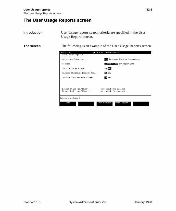
User Usage reports 32-3The User Usage Reports screen
en.
The User Usage Reports screen
Introduction User Usage reports search criteria are specified in the User Usage Reports screen.
The screen The following is an example of the User Usage Reports scre
Standard 1.0 System Administration Guide January 1998
32-4 User Usage reports Fields in the User Usage Reports screen
en. type
ers
me me on
ox se
x
ent
to ,
Fields in the User Usage Reports screen
Introduction The following fields appear on the User Usage Reports screSelect parameters and choose options required to create theof report you need.
Selection Criteria The following options are search parameters. Statistics matching your selection are displayed in the report.
AllWhen this option is selected, user usage data for all local uswill be displayed in the report.
LastnameWhen this option is selected, you are prompted for the last naof the subscriber whose data you want to view. If the last nais not found, use the Find Users feature in User Administratito verify that the name exists in the system. You may use wildcard characters (“+”, “?”, or “_”) to retrieve a group of users.
MailboxWhen this option is selected, you are prompted for the mailbnumber of the user whose data you want to view. You may uwildcard characters (“+”, “?”, or “_”) to retrieve a range of mailboxes. If the mailbox number is not found, use the Find Users feature in User Administration to verify that the mailbonumber exists in the system.
DepartmentWhen this option is selected, you are prompted for a departmname. All users associated with that department will be displayed in the report. The entry you make must correspondan existing entry in the system. Use wildcard characters (“+”“?”, or “_”) to retrieve a group of departments.
Note: When searching by department, users with blank department fields will not be displayed.
Standard 1.0 System Administration Guide January 1998
User Usage reports 32-5Fields in the User Usage Reports screen
t
de
on er g the l,
e
well hree
for
ers th
Sorted If your selection criterion is All Users, you can choose to sorthe user data alphabetically, according to user names, or according to department names.
Note: When sorting by department, users with blank department fields will not be displayed.
Include Local Usage This field is displayed if Meridian Networking and/or AMIS Networking are enabled. (If networking is not installed, the report displays only local usage.) Set the field to Yes to incluuser usage data for local voice messaging. This includes information about the number of Express Messaging and logsessions the user had during the specified interval, the numbof messages that were created during the Express Messaginand logon sessions and the total length of those messages, amount of time that the user was connected to Meridian Maiand the amount of disk space used by those messages. Thedefault is Yes.
Include Meridian Network Usage
This field is displayed if Meridian Networking is enabled. When this field is set to Yes, the report will include user usagdata for Meridian Networking activity. This information includes the number of economy, standard, and urgent messages that users created during the specified interval asas the total length of the messages created (for each of the ttypes of messages). The default is No.
Include AMIS Network Usage
This field is displayed if AMIS Networking is enabled. When this field is set to Yes, the report will include user usage dataAMIS Networking activity. This information includes the number of economy, standard, and urgent messages that uscreated during the specified interval as well as the total lengof the messages created (for each of the three types of messages). The default is No.
Standard 1.0 System Administration Guide January 1998
32-6 User Usage reports Fields in the User Usage Reports screen
tarts ve l
ds on
n,
Report Start(mm/dd/yy)
This is the date on which the selected reports are to start. If Report Start predates the earliest available date, the report swith the earliest available date. Leave this field blank to retriereports for the earliest available data. (The format mm/dd/yyhh:mm is the default. The format can be changed in GeneraAdministration, General Options. For more information, see Chapter 13, “General options”.
Report End(mm/dd/yy)
This is the date on which the selected reports are to end. If Report End exceeds the latest available period, the report enwith the last available period. Leave this field blank to report the most recent data. (The format mm/dd/yy hh:mm is the default. The format can be changed in General AdministratioGeneral Options. For more information, see Chapter 13, “General options”.
Standard 1.0 System Administration Guide January 1998
User Usage reports 32-7Generating User Usage reports
te
Generating User Usage reports
Introduction The following information describes the procedure to generaUser Usage reports.
Procedure To generate User Usage reports, follow these steps.
Starting Point: Main Menu
Step Action
1 Select Operational Measurements.
Result: The Operational Measurements screen is displayed.
2 Select User Usage Reports from the Operational Measurements menu.
Result: The User Usage Reports screen is displayed.
3 Choose the selection criteria by which you want to retrieve data.
4 If the selection criterion is All, select how you want the data to be sorted: alphabetically (by user name) or by department name.
5 Select the type of data you want to view: local usage, Meridian Networking, or AMIS Network usage. You can select all three if required.
Note: Meridian Networking and AMIS Networking usage are available only if Meridian Networking or AMIS Networking is installed.
6 If you wish to specify a start and stop time for the reporting period, enter the required values in the Report Start and Report End fields.
7 Choose one of the following options.
TO GO to step
view User Usage reports 8.
print User Usage reports 9.
exit User Usage reports 10.
Standard 1.0 System Administration Guide January 1998
32-8 User Usage reports Generating User Usage reports
8 Press [View Reports].
Result: The selected report screens are displayed (see the following pages for descriptions of each report).
Press [Next Page] to view subsequent pages of the report; press [Exit] to return to the User Usage Reports screen.
9 Press [Print Reports].
Result: You are prompted to make sure that your printer is ready and online.
Press [Continue Printing] to print the reports, or press [Cancel Printing] at any time to cancel printing. There may be some delay before control is returned to the screen because it waits for the printer to stop printing.
10 Press [Exit].
The Operational Measurements menu is redisplayed.
Step Action
Standard 1.0 System Administration Guide January 1998
User Usage reports 32-9User Usage report
he
User Usage report
Introduction When you view the report on the terminal or from a printout, tdata is arranged as shown in the diagram below. These examples show all types of user usage data (local, MeridianNetworking, and AMIS Networking).
The screen The following is an example of the User Usage report.
RecordsLang Kathy 15
AdmissionsPotts Brian
Standard 1.0 System Administration Guide January 1998
32-10 User Usage reports User Usage report
The following is an example of a User Usage report when Meridian Networking and AMIS Networking is installed.
6/10/96 10 3:10 1 1:30 0 00:00
6/10/96Total------------------------------------------------------------------------
8 2:23 7 11:40 0 00:00 8 2:23 7 11:40 0 00:00
10 3:10 1 1:30 0 00:00
Delray Marina Executive
6/10/96
Standard 1.0 System Administration Guide January 1998
User Usage reports 32-11Fields in the User Usage report
ort.
nd e
.
y
Fields in the User Usage report
Introduction These are the fields that are displayed in the User Usage rep
Header fields Last NameThis is the user’s last name.
First NameThis is the user’s first name.
DepartmentThis is the user’s department name.
Mailbox This is the user’s mailbox number.
COS This is the class of service number assigned to the user.
Local Usage fields DateThis is the date of the reporting interval.
Number of SessionsThis is the number of Express Messaging, Call Answering, alogon sessions that occurred during the interval. To check thnumber of messages that were actually received or created during these sessions, check the Number of Messages field
• EM/Ans refers to the total number of sessions created bExpress Messaging or Call Answering calls to this mailbox. The number of abandoned calls (where no message is left) can be calculated by subtracting the number of EM/Ans messages from the number of EM/Ans sessions.
• Logon refers to the number of times the user logged intothe mailbox for any reason.
Standard 1.0 System Administration Guide January 1998
32-12 User Usage reports Fields in the User Usage report
ser
r’s
ting /
user
ge
ted
and
Connect Time (mm:ss)This is the length of time (in minutes and seconds) that the uwas connected to the Voice Messaging service on the givendate.
Number of Messages This is the number of messages that the user received and created on the given date.
• EM/Ans refers to the number of messages left in the usemailbox by both the Express Messaging and Call Answering services. The number of abandoned calls (where no message is left) can be calculated by subtracthe number of EM/Ans messages from the number of EMAns sessions.
• Logon refers to the number of messages that the user created on the report date.
Message Length (mm:ss) This is the total time (in minutes and seconds) of all call answering messages received and messages created by theor deposited in the user’s mailbox on the given date.
Disk Used (mm:ss)This is the amount of storage used by the user (measured inminutes and seconds) on the given date. This includes storafor greetings and personal verifications (spoken name recordings).
Meridian and AMIS Networking usage fields
Date This is the date of the reporting interval.
Number of Economy Messages This is the number of economy messages that the user creaon the given date.
Total Length (mm:ss)This is the total length (in minutes and seconds) of all networking messages created by the user on the given datetagged as economy.
Standard 1.0 System Administration Guide January 1998
User Usage reports 32-13Fields in the User Usage report
d on
and
on
and
Number of Standard Messages This is the number of standard messages that the user createthe given date.
Total Length (mm:ss)This is the total length (in minutes and seconds) of all networking messages created by the user on the given datetagged as standard.
Number of Urgent Messages This is the number of urgent messages that the user createdthe given date.
Total Length (mm:ss) This is the total length (in minutes and seconds) of all networking messages created by the user on the given datetagged as urgent.
Standard 1.0 System Administration Guide January 1998
32-14 User Usage reports Analyzing User Usage reports
mit
s of
ge
”)
sed ser
ave g
Analyzing User Usage reports
The EM/Ans numbers are high and the logon count is low
The user may be accumulating too many messages before checking the mailbox and thereby contributing to a low disk space problem.
Suggested actionIf disk space is already low (check the Disk Usage Detail report), you may need to make the user more aware of the importance of not accumulating messages.
Monitor the length of messages closely. If messages are toolong for some users, you may wish to shorten their storage lito encourage the users to empty their mailboxes more frequently. (For more information, see Chapter 7, “User administration—an overview”.) You can also alter the maximum message length parameter (see Chapter 26, “ClasService administration”) to deter callers from leaving long messages.
You can assign a class of service (COS) with a shorter storalimit to encourage the users to empty their mailboxes more frequently (see Chapter 7, “User administration—an overview”). You can also alter the maximum message lengthparameter (see Chapter 26, “Class of Service administrationto deter callers from leaving long messages.
The number of logons is zero
Suggested actionCheck the Time of Last Logon field in the View/Modify LocalVoice User screen. If a considerable amount of time has passince the last successful logon, you may want to contact the uto see if he or she is having any problems logging on. For example, the user may not know how to log on and retrieve messages (especially if this is a new user), or the user may hforgotten the mailbox password and has stopped trying to loon.
Standard 1.0 System Administration Guide January 1998
Chapter 33
Audit Trail reports
In this chapter
Overview 33-2
Section A: Collecting Audit Trail data 33-3
Section B: Outcalling Audit Trail reports 33-9
Section C: Fax Audit Trail reports 33-29
33-2 Audit Trail reports Overview
re
s
Overview
Introduction This chapter describes the two types of Operational Measurement (OM) Audit Trail reports—Outcalling and Fax.These reports are useful for monitoring the use of these twofeatures.
Section A: Collecting Audit Trail data, describes the procedufor enabling the collection of audit trail data.
Section B: Outcalling Audit Trail reports, provides descriptionand analyses for the Outcalling Audit Trail reports.
Section C: Fax Audit Trail reports, provides examples, descriptions, and analyses for the Fax Audit Trail reports.
Standard 1.0 System Administration Guide January 1998
Audit Trail reports 33-3
Section A: Collecting Audit Trail data
In this section
Overview 33-4
Enabling the collection of audit trail data 33-5
Standard 1.0 System Administration Guide January 1998
33-4 Audit Trail reports Overview
ns it
Overview
Introduction This section describes the Operational Measurements Optioscreen and the procedure for setting up the collection of audtrail data.
Standard 1.0 System Administration Guide January 1998
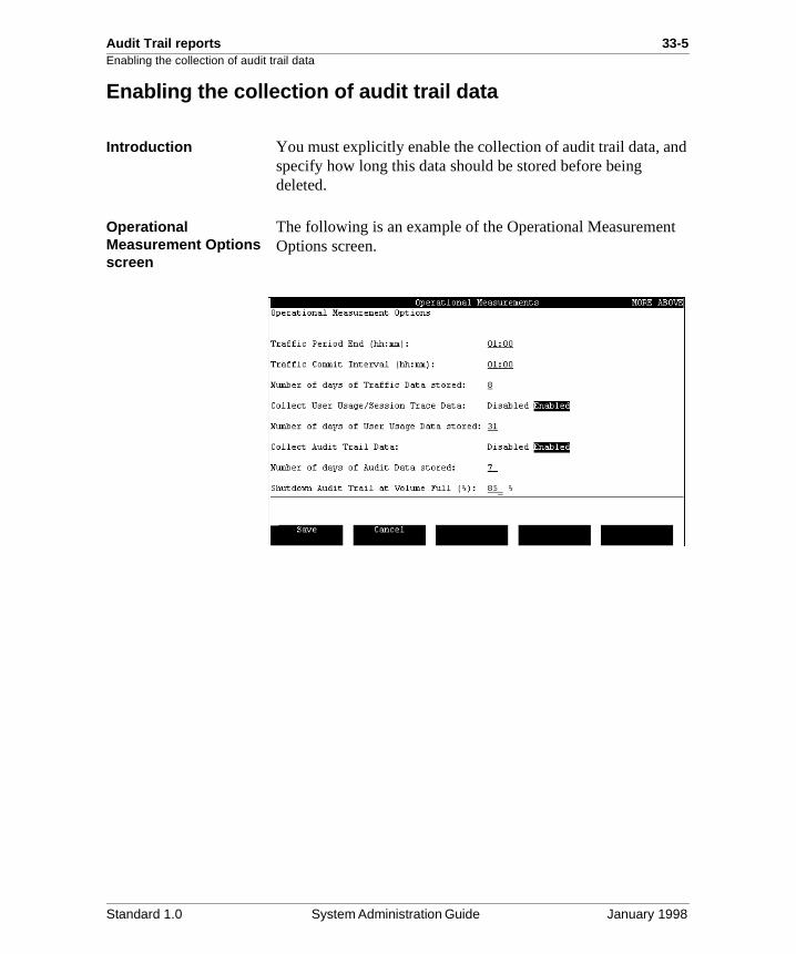
Audit Trail reports 33-5Enabling the collection of audit trail data
d
t
Enabling the collection of audit trail data
Introduction You must explicitly enable the collection of audit trail data, anspecify how long this data should be stored before being deleted.
Operational Measurement Options screen
The following is an example of the Operational MeasuremenOptions screen.
Standard 1.0 System Administration Guide January 1998
33-6 Audit Trail reports Enabling the collection of audit trail data
it
f
e
Fields used to enable audit trail data collection
These fields are used to enable audit trail data collection.
Collect Audit Trail Data
Description This field determines whether or not audit trail data is collected.
Options Enabled and Disabled
Default Enabled
Number of days of Audit Data stored
Description The field determines how long the collected audtrail data will be stored on disk before being overwritten.
Range 1 to 63 days
Default 7
Shutdown Audit Trail at Volume Full (%)
Description Use this field to identify the percentage at which you want the collection of audit trail data to stop.
Example If set to 80%, audit trail data collection is disabledwhen the volume on which audit data is stored reaches 80% capacity. If set to 100%, collection odata will not stop until the volume is completely full. This is not recommended.
Note: This is a percentage of text space, not voicspace.
Default 85%
Standard 1.0 System Administration Guide January 1998
Audit Trail reports 33-7Enabling the collection of audit trail data
.
Procedure To enable the collection of audit trail data, follow these stepsStarting Point: The Main Menu
Step Action
1 Select Operational Measurements.
2 Select Operational Measurement Options.
Result: The Operational Measurement Options screen is displayed. Three fields on the screen (Collect Audit Trail Data, Number of days of Audit Data stored, and Shutdown Audit Trail at Volume Full) are used to enable audit trail data collection.
3 Set the Collect Audit Trail Data field to Enabled if currently disabled (Enabled is the default.)
4 Specify the number of days that audit trail data should be stored on disk.
Note: Detailed field descriptions are provided on the preceding pages.
5 In the Shutdown Audit Trail at Volume Full (%) field, enter the percentage full at which collection of audit trail data should stop.
The default is 85%.
6 To save the current configuration, go to step 7. To exit without saving, go to step 8.
7 Press [Save].
Result: The outcalling data is saved and you are returned to the Operational Measurements menu.
8 Press [Cancel].
Result: Any changes you have made are not saved and you are returned to the Operational Measurements menu.
Standard 1.0 System Administration Guide January 1998

33-8 Audit Trail reports Enabling the collection of audit trail data
Standard 1.0 System Administration Guide January 1998
Chapter 33
Audit Trail reports 33-9Section B: Outcalling Audit Trail reports
In this section
Overview 33-10
Generating an Outcalling Audit Trail report 33-11
The Summary Outcalling Audit Trail report 33-15
Fields in the Summary Outcalling Audit Trail report 33-16
Analyzing the Summary Outcalling Audit Trail report 33-18
The Detail Outcalling Audit Trail report 33-19
Fields in the Detail Outcalling Audit Trail report 33-20
Analyzing the Detail Outcalling Audit Trail report 33-28
Standard 1.0 System Administration Guide January 1998
33-10 Audit Trail reports
s
il iod
as
r, d)
all, e
Overview
Overview
Introduction Outcalling audit trail statistics allow you to monitor how userare using the Remote Notification (RN) and Delivery to Non-User (DNU) features. There are two Outcalling Audit Trail reports that you can generate: a summary report and a detareport. Each report provides outcalling data for a certain perof time as specified by you.
Report types The following two report types are available for Outcalling.
Outcalling Audit Trail Summary reportThe summary report shows each outcall (RN or DNU) that wmade during the reporting interval, along with the user who made the call, the user’s mailbox number, the target numbeand the status of the call. It shows only completed (answerecalls.
Outcalling Audit Trail Detail reportThe detail report provides a more thorough account of each outcall request, including the start time and duration of the cthe DN of the channel that was used to place the call, and thnumber of retries (if any). It shows all outcalls, both successfully completed and unsuccessful.
Standard 1.0 System Administration Guide January 1998
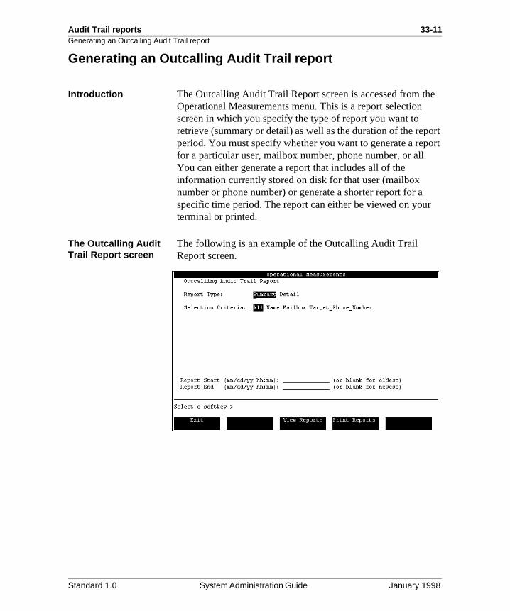
Audit Trail reports 33-11Generating an Outcalling Audit Trail report
e
ort ort
r
Generating an Outcalling Audit Trail report
Introduction The Outcalling Audit Trail Report screen is accessed from thOperational Measurements menu. This is a report selection screen in which you specify the type of report you want to retrieve (summary or detail) as well as the duration of the repperiod. You must specify whether you want to generate a repfor a particular user, mailbox number, phone number, or all. You can either generate a report that includes all of the information currently stored on disk for that user (mailbox number or phone number) or generate a shorter report for aspecific time period. The report can either be viewed on youterminal or printed.
The Outcalling Audit Trail Report screen
The following is an example of the Outcalling Audit Trail Report screen.
Standard 1.0 System Administration Guide January 1998
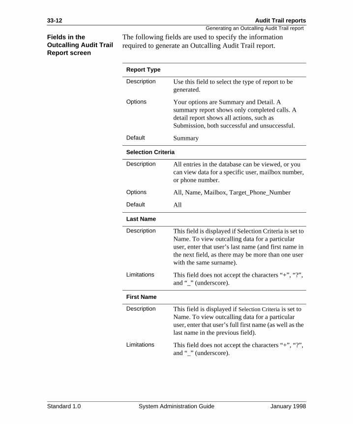
33-12 Audit Trail reports
r,
in er
,
e
,
Generating an Outcalling Audit Trail report
Fields in the Outcalling Audit Trail Report screen
The following fields are used to specify the information required to generate an Outcalling Audit Trail report.
Report Type
Description Use this field to select the type of report to be generated.
Options Your options are Summary and Detail. A summary report shows only completed calls. A detail report shows all actions, such as Submission, both successful and unsuccessful.
Default Summary
Selection Criteria
Description All entries in the database can be viewed, or youcan view data for a specific user, mailbox numbeor phone number.
Options All, Name, Mailbox, Target_Phone_Number
Default All
Last Name
Description This field is displayed if Selection Criteria is set toName. To view outcalling data for a particular user, enter that user’s last name (and first namethe next field, as there may be more than one uswith the same surname).
Limitations This field does not accept the characters “+”, “?”and “_” (underscore).
First Name
Description This field is displayed if Selection Criteria is set to Name. To view outcalling data for a particular user, enter that user’s full first name (as well as thlast name in the previous field).
Limitations This field does not accept the characters “+”, “?”and “_” (underscore).
Standard 1.0 System Administration Guide January 1998
Audit Trail reports 33-13Generating an Outcalling Audit Trail report
r
h
ps.
r er
e
Note: If NMS is installed, you may enter a mailbox number foa voice user at another location, prefixed by the appropriatelocation code. However, if Meridian Networking is installed, you cannot use a remote user’s mailbox number as a searccriterion.
Procedure To generate an Outcalling Audit Trail report, follow these ste
Starting Point: The Main Menu
Mailbox
Description This field is displayed if Selection Criteria is set to Mailbox. To view outcalling data for a specific mailbox, enter the full mailbox number.
Limitations This field accepts numeric data only.
Target Phone Number
Description This field is displayed if Selection Criteria is set to Target Phone Number. To view outcalling data foa particular target phone number or pager numb(the number entered in the Target DN field in the outcalling schedule), enter the full number in thisfield.
Limitations This field accepts numeric data only.
Report Start/End
Description Enter the start date and time and end date and timto indicate the reporting period.
Step Action
1 Select Operational Measurements.
2 Select Outcalling Audit Trail Report.
Result: The Outcalling Audit Trail Report screen is displayed.
3 Specify the report type (Summary or Detail).
4 Specify the selection criteria (Name, Mailbox, Target Phone Number, or All).
5 Fill in the field that corresponds to the selection criteria you choose.
Standard 1.0 System Administration Guide January 1998
33-14 Audit Trail reports
Generating an Outcalling Audit Trail report6 Enter the report start and end times.
Note: If these fields are left blank, all outcalling data that is currently stored on disk will be retrieved.
7 Choose step 8 to view the reports on the terminal or step 9 to print the reports.
8 Press [View Reports].
Result: The first Outcalling Audit Trail report is displayed.
When viewing the report, press [Next Page] to view the next page of the report. When the last page has been displayed, a prompt appears indicating it is the end of the report.
Note: For a description of the fields in the summary report, see “Fields in the Summary Outcalling Audit Trail report” in this chapter. For a description of the fields in the detail report, see “Fields in the Detail Outcalling Audit Trail report” in this chapter.
9 Press [Print Reports].
Result: You are prompted to ensure the printer is ready and online.
Press [Continue Printing] to print the report or [Cancel] if you do not want to print the report.
If you selected [Continue Printing], a [Cancel] softkey is displayed that can be used to cancel printing once printing has started.
There may be some delay before control is returned to the screen because it waits for the printer to stop printing.
10 Press [Exit].
You are returned to the Outcalling Audit Trail Report screen.
Step Action
Standard 1.0 System Administration Guide January 1998
Audit Trail reports 33-15The Summary Outcalling Audit Trail report
port. he
it
The Summary Outcalling Audit Trail report
Introduction The Summary Outcalling Audit Trail report is displayed if youselect Summary as the report type when you generate the reThis report provides summary information about the use of tRemote Notification (RN) and Delivery to Non-User (DNU) features.
The report The following is an example of the Summary Outcalling AudTrail report screen.
14:40 0:50 91236789 DNU Answered
Smith, J 7550
12:40 1:10 91238765 DNU Answered12:45 0:05 91238765 DNU No DTMF Conf.13:45 0:18 8051-345643 RN Answered
Standard 1.0 System Administration Guide January 1998
33-16 Audit Trail reports
ch
w
the
to
Fields in the Summary Outcalling Audit Trail report
Fields in the Summary Outcalling Audit Trail report
Introduction The following informational fields are displayed when you generate a Summary Outcalling Audit Trail report.
Date The date the call was made.
Name The name of the Meridian Mail user who initiated the call.
Mailbox Number The mailbox that originated the call.
Start (hh:mm) The time at which the call was made.
Duration (mm:ss) The length of the call in minutes and seconds.
Target Phone Number This is the number called. A maximum of 30 digits can be displayed in this field. For calls placed to paging services (suas SkyPager), the pager identification number (PIN) is also displayed.
ExampleIn the number 8051-345643, the last six digits are the PIN number. If the full number is longer than 30 digits, the first fedigits in the paging service phone number will be truncated.
Type The Outcalling service that was used: either Remote Notification or Delivery to Non-User.
Call Status The result of the call. The result status can be one of the following types.
AnsweredThis indicates that the destination number was answered andmessage was heard by the called party.
RN Disabled This indicates that the called party answered and pressed 3 disable Remote Notification (RN).
Standard 1.0 System Administration Guide January 1998
Audit Trail reports 33-17Fields in the Summary Outcalling Audit Trail report
ot
re
Call Status (cont’d) No DTMF Conf.This display indicates that the called party did not press 2 tohear a DNU message (not relevant if DTMF confirmation is nrequired).
Not PlayedThis display indicates that the called party disconnected befothe DNU message was played.
Standard 1.0 System Administration Guide January 1998
33-18 Audit Trail reports
g
N
nd
Analyzing the Summary Outcalling Audit Trail report
Analyzing the Summary Outcalling Audit Trail report
Introduction This report provides a list of the type and result of all outcallinattempts during the specified period.
Invalid RN target If a particular RN target is associated with RN failures, the Rtarget may be invalid. Check to see if only one mailbox is associated with the invalid RN target. If so, contact the user asuggest that the target RN be corrected, or correct the RN through the Meridian Mail interface. If multiple mailboxes areassociated with the faulty RN target, determine why the RN target is no longer valid.
Standard 1.0 System Administration Guide January 1998
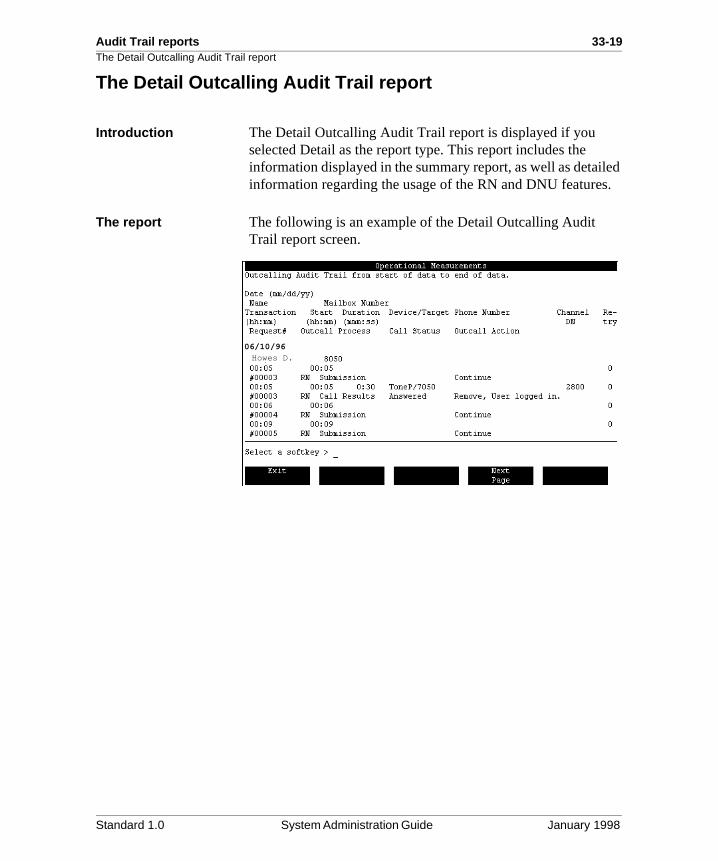
Audit Trail reports 33-19The Detail Outcalling Audit Trail report
led s.
The Detail Outcalling Audit Trail report
Introduction The Detail Outcalling Audit Trail report is displayed if you selected Detail as the report type. This report includes the information displayed in the summary report, as well as detaiinformation regarding the usage of the RN and DNU feature
The report The following is an example of the Detail Outcalling Audit Trail report screen.
Howes D.06/10/96
Standard 1.0 System Administration Guide January 1998
33-20 Audit Trail reports
red
e/s:
ne
g
d.
Fields in the Detail Outcalling Audit Trail report
Fields in the Detail Outcalling Audit Trail report
Introduction The following fields are displayed when the Detail OutcallingAudit Trail report is chosen.
Date This is the date the call was made.
Name This is the name of the Meridian Mail user who initiated the call.
Mailbox Number This is the mailbox that originated the call.
Transaction (hh:mm) This indicates the time at which the audit trail record was sto(using 24-hour clock).
Start (hh:mm) This indicates the time at which the current outcall process started (using 24-hour clock).
Duration (mm:ss) This indicates the length of the call.
Device/Target Phone Number
This indicates the type of device called followed by the phonpager number. The device will be one of the following choice
• Phone
• ToneP (tone pager)
• Voice (voice pager)
• NumPa (numeric pager)
• PaSrv (pager service)
Note: If the device is a paging service, the paging service phonumber, followed by the pager identification number (PIN), will be displayed. The maximum length for this field is 30 digits. If this limit is exceeded, the first few digits of the paginservice phone number will be truncated.
Channel DN This indicates the DN associated with the voice channel use
Standard 1.0 System Administration Guide January 1998
Audit Trail reports 33-21Fields in the Detail Outcalling Audit Trail report
e
ied
he
ng no
he d
new the
e e
/is
Retry This shows the number of retries that have been made at thtime of the attempt. This field increments by one whenever
• a DN is busy and is retried
• multiple target DNs are defined and they have all been trand either not answered or answered with no login
Transaction Request # This is a unique number identifying the RN or DNU request.
Outcall Process This shows the type of audit trail entry. This could be one of tfollowing.
SubmissionThis type indicates that a request has been made for an Outcalling service.
RecoveryThis type indicates that messages for outcalling have been detected and submitted after a system reboot.
CancellationThis type indicates that during recovery, requests for outcallihave been detected but have been cancelled since they arelonger valid.
Logout/AdminThis type indicates that one of two conditions has occurred. Tfirst possibility is that a user has logged out with unannouncemessages left in his or her mailbox. Normally, if a user is listening to a message when a new message comes in, the message is announced after the user has finished listening toother message. However, if the user hangs up before the message has finished playing, the new message will not be announced. (In this situation, the user will continue to be notified of messages.) The second possibility is that someon(an administrator or you) has modified a user’s account whilthere were unread messages in the user’s mailbox.
ValidationThis type indicates a checking process just before a call wasmade.
Standard 1.0 System Administration Guide January 1998
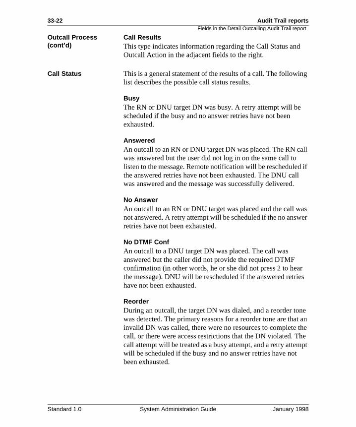
33-22 Audit Trail reports
ing
all d if ll .
as er
r es
ne t an
the he mpt
Fields in the Detail Outcalling Audit Trail report
Outcall Process (cont’d)
Call ResultsThis type indicates information regarding the Call Status andOutcall Action in the adjacent fields to the right.
Call Status This is a general statement of the results of a call. The followlist describes the possible call status results.
BusyThe RN or DNU target DN was busy. A retry attempt will be scheduled if the busy and no answer retries have not been exhausted.
AnsweredAn outcall to an RN or DNU target DN was placed. The RN cwas answered but the user did not log in on the same call tolisten to the message. Remote notification will be reschedulethe answered retries have not been exhausted. The DNU cawas answered and the message was successfully delivered
No AnswerAn outcall to an RN or DNU target was placed and the call wnot answered. A retry attempt will be scheduled if the no answretries have not been exhausted.
No DTMF ConfAn outcall to a DNU target DN was placed. The call was answered but the caller did not provide the required DTMF confirmation (in other words, he or she did not press 2 to heathe message). DNU will be rescheduled if the answered retrihave not been exhausted.
ReorderDuring an outcall, the target DN was dialed, and a reorder towas detected. The primary reasons for a reorder tone are thainvalid DN was called, there were no resources to complete call, or there were access restrictions that the DN violated. Tcall attempt will be treated as a busy attempt, and a retry attewill be scheduled if the busy and no answer retries have notbeen exhausted.
Standard 1.0 System Administration Guide January 1998
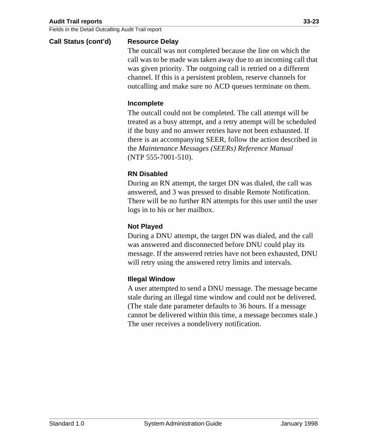
Audit Trail reports 33-23Fields in the Detail Outcalling Audit Trail report
e that
.
led If in
s . er
ll
DNU
came d. le.)
Call Status (cont’d) Resource DelayThe outcall was not completed because the line on which thcall was to be made was taken away due to an incoming call was given priority. The outgoing call is retried on a different channel. If this is a persistent problem, reserve channels foroutcalling and make sure no ACD queues terminate on them
IncompleteThe outcall could not be completed. The call attempt will be treated as a busy attempt, and a retry attempt will be scheduif the busy and no answer retries have not been exhausted. there is an accompanying SEER, follow the action describedthe Maintenance Messages (SEERs) Reference Manual (NTP 555-7001-510).
RN DisabledDuring an RN attempt, the target DN was dialed, the call waanswered, and 3 was pressed to disable Remote NotificationThere will be no further RN attempts for this user until the uslogs in to his or her mailbox.
Not PlayedDuring a DNU attempt, the target DN was dialed, and the cawas answered and disconnected before DNU could play its message. If the answered retries have not been exhausted, will retry using the answered retry limits and intervals.
Illegal WindowA user attempted to send a DNU message. The message bestale during an illegal time window and could not be delivere(The stale date parameter defaults to 36 hours. If a messagecannot be delivered within this time, a message becomes staThe user receives a nondelivery notification.
Standard 1.0 System Administration Guide January 1998
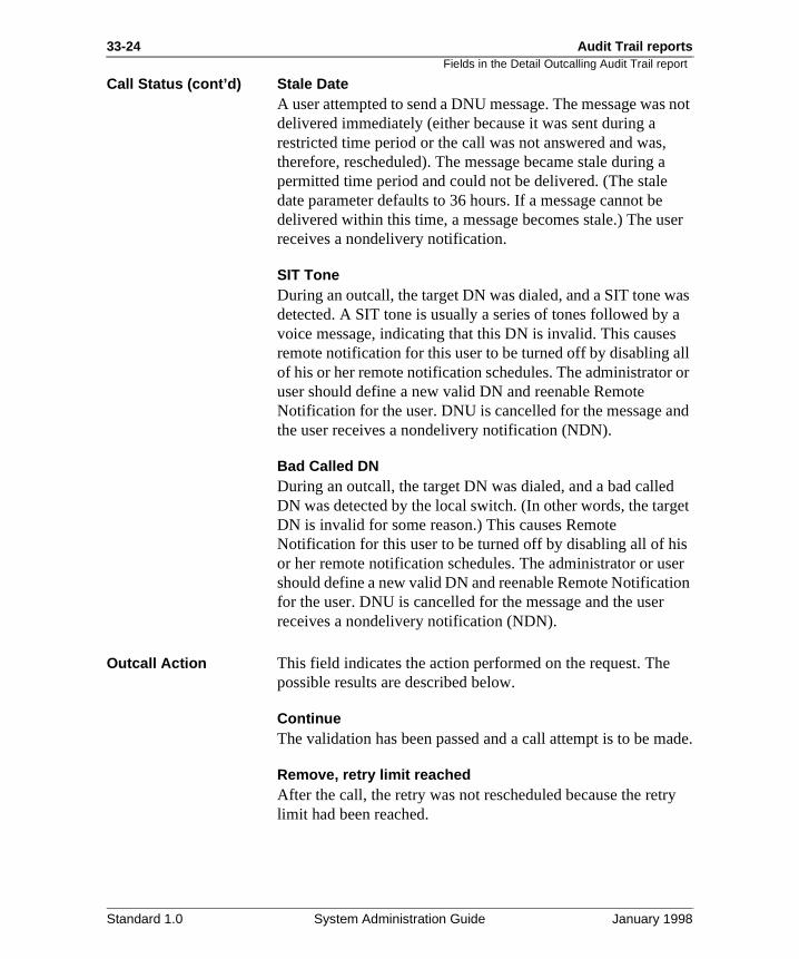
33-24 Audit Trail reports
s not
a
ser
as a s ll
or
nd
get
s er on
ade.
ry
Fields in the Detail Outcalling Audit Trail report
Call Status (cont’d) Stale DateA user attempted to send a DNU message. The message wadelivered immediately (either because it was sent during a restricted time period or the call was not answered and was,therefore, rescheduled). The message became stale during permitted time period and could not be delivered. (The staledate parameter defaults to 36 hours. If a message cannot bedelivered within this time, a message becomes stale.) The ureceives a nondelivery notification.
SIT ToneDuring an outcall, the target DN was dialed, and a SIT tone wdetected. A SIT tone is usually a series of tones followed byvoice message, indicating that this DN is invalid. This causeremote notification for this user to be turned off by disabling aof his or her remote notification schedules. The administratoruser should define a new valid DN and reenable Remote Notification for the user. DNU is cancelled for the message athe user receives a nondelivery notification (NDN).
Bad Called DNDuring an outcall, the target DN was dialed, and a bad calledDN was detected by the local switch. (In other words, the tarDN is invalid for some reason.) This causes Remote Notification for this user to be turned off by disabling all of hior her remote notification schedules. The administrator or usshould define a new valid DN and reenable Remote Notificatifor the user. DNU is cancelled for the message and the userreceives a nondelivery notification (NDN).
Outcall Action This field indicates the action performed on the request. Thepossible results are described below.
ContinueThe validation has been passed and a call attempt is to be m
Remove, retry limit reachedAfter the call, the retry was not rescheduled because the retlimit had been reached.
Standard 1.0 System Administration Guide January 1998
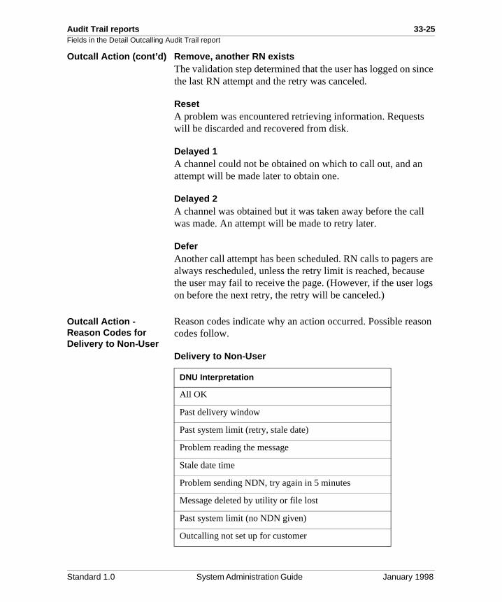
Audit Trail reports 33-25Fields in the Detail Outcalling Audit Trail report
ince
ll
are se gs
son
Outcall Action (cont’d) Remove, another RN existsThe validation step determined that the user has logged on sthe last RN attempt and the retry was canceled.
ResetA problem was encountered retrieving information. Requestswill be discarded and recovered from disk.
Delayed 1A channel could not be obtained on which to call out, and anattempt will be made later to obtain one.
Delayed 2A channel was obtained but it was taken away before the cawas made. An attempt will be made to retry later.
DeferAnother call attempt has been scheduled. RN calls to pagersalways rescheduled, unless the retry limit is reached, becauthe user may fail to receive the page. (However, if the user loon before the next retry, the retry will be canceled.)
Outcall Action -Reason Codes for Delivery to Non-User
Reason codes indicate why an action occurred. Possible reacodes follow.
Delivery to Non-User
DNU Interpretation
All OK
Past delivery window
Past system limit (retry, stale date)
Problem reading the message
Stale date time
Problem sending NDN, try again in 5 minutes
Message deleted by utility or file lost
Past system limit (no NDN given)
Outcalling not set up for customer
Standard 1.0 System Administration Guide January 1998
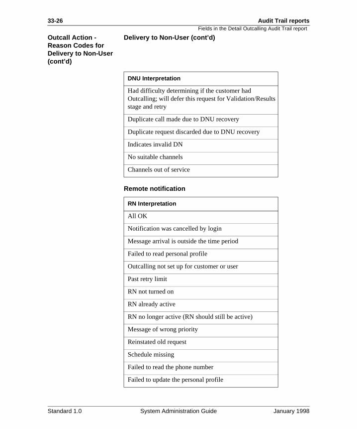
33-26 Audit Trail reports
Fields in the Detail Outcalling Audit Trail reportOutcall Action -Reason Codes for Delivery to Non-User (cont’d)
Delivery to Non-User (cont’d)
Remote notification
DNU Interpretation
Had difficulty determining if the customer had Outcalling; will defer this request for Validation/Results stage and retry
Duplicate call made due to DNU recovery
Duplicate request discarded due to DNU recovery
Indicates invalid DN
No suitable channels
Channels out of service
RN Interpretation
All OK
Notification was cancelled by login
Message arrival is outside the time period
Failed to read personal profile
Outcalling not set up for customer or user
Past retry limit
RN not turned on
RN already active
RN no longer active (RN should still be active)
Message of wrong priority
Reinstated old request
Schedule missing
Failed to read the phone number
Failed to update the personal profile
Standard 1.0 System Administration Guide January 1998
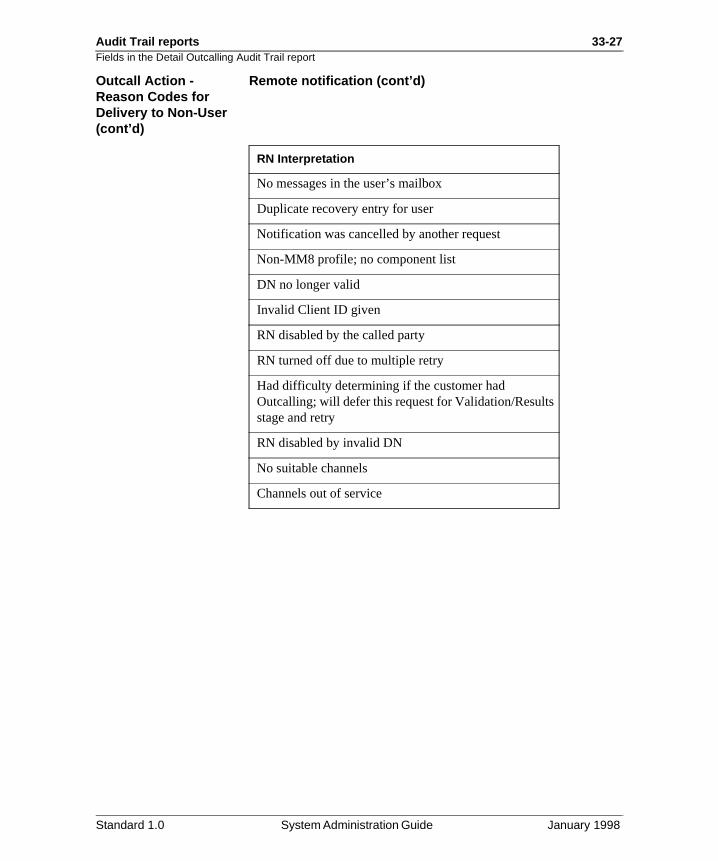
Audit Trail reports 33-27Fields in the Detail Outcalling Audit Trail report
Outcall Action -Reason Codes for Delivery to Non-User (cont’d)
Remote notification (cont’d)
RN Interpretation
No messages in the user’s mailbox
Duplicate recovery entry for user
Notification was cancelled by another request
Non-MM8 profile; no component list
DN no longer valid
Invalid Client ID given
RN disabled by the called party
RN turned off due to multiple retry
Had difficulty determining if the customer had Outcalling; will defer this request for Validation/Results stage and retry
RN disabled by invalid DN
No suitable channels
Channels out of service
Standard 1.0 System Administration Guide January 1998
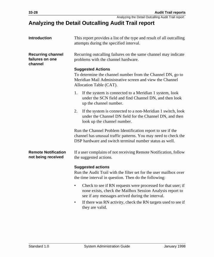
33-28 Audit Trail reports
g
ate
to
ok n
the
w
r
r; if to
e if
Analyzing the Detail Outcalling Audit Trail report
Analyzing the Detail Outcalling Audit Trail report
Introduction This report provides a list of the type and result of all outcallinattempts during the specified interval.
Recurring channel failures on one channel
Recurring outcalling failures on the same channel may indicproblems with the channel hardware.
Suggested ActionsTo determine the channel number from the Channel DN, go Meridian Mail Administrative screen and view the Channel Allocation Table (CAT).
1. If the system is connected to a Meridian 1 system, look under the SCN field and find Channel DN, and then lookup the channel number.
2. If the system is connected to a non-Meridian 1 switch, lounder the Channel DN field for the Channel DN, and thelook up the channel number.
Run the Channel Problem Identification report to see if the channel has unusual traffic patterns. You may need to checkDSP hardware and switch terminal number status as well.
Remote Notification not being received
If a user complains of not receiving Remote Notification, follothe suggested actions.
Suggested actionsRun the Audit Trail with the filter set for the user mailbox ovethe time interval in question. Then do the following:
• Check to see if RN requests were processed for that usenone exists, check the Mailbox Session Analysis report see if any messages arrived during the interval.
• If there was RN activity, check the RN targets used to sethey are valid.
Standard 1.0 System Administration Guide January 1998
Chapter 33
Audit Trail reports 33-29Section C: Fax Audit Trail reports
In this section
Overview 33-30
The Fax Audit Trail Report screen 33-31
The Summary Fax Audit Trail report 33-35
Fields in the Summary Fax Audit Trail report screen 33-36
Analyzing the Summary Fax Audit Trail report 33-37
The Detail Fax Audit Trail report 33-38
Fields in the Detail Fax Audit Trail report screen 33-39
Analyzing the Detail Fax Audit Trail report 33-43
Standard 1.0 System Administration Guide January 1998
33-30 Audit Trail reports
ax nd
dit il
e
d
Overview
Overview
Introduction Fax audit trail statistics allow you to monitor how users are using the Fax on Demand features. There are actually two FAudit Trail reports that you can generate: a summary report aa detail report. Each report provides fax data for a period specified by you.
Note: Before you can generate a Fax Audit Trail report, the Meridian Mail system must be set so that the collection of autrail data is enabled (see “Enabling the collection of audit tradata” on page 33-5).
Report types The following two types of Fax Audit Trail Data reports are available.
Summary reportThe summary report shows each fax outcall that was made during the reporting interval, along with the called DN and thstatus of the call.
Detail reportThe detail report provides a more thorough account of each outcall request, including the DN of the channel that was useto place the call and the number of retries (if any).
Standard 1.0 System Administration Guide January 1998
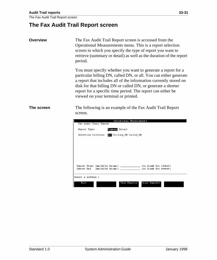
Audit Trail reports 33-31The Fax Audit Trail Report screen
ort
a te n
The Fax Audit Trail Report screen
Overview The Fax Audit Trail Report screen is accessed from the Operational Measurements menu. This is a report selection screen in which you specify the type of report you want to retrieve (summary or detail) as well as the duration of the repperiod.
You must specify whether you want to generate a report for particular billing DN, called DN, or all. You can either generaa report that includes all of the information currently stored odisk for that billing DN or called DN, or generate a shorter report for a specific time period. The report can either be viewed on your terminal or printed.
The screen The following is an example of the Fax Audit Trail Report screen.
Standard 1.0 System Administration Guide January 1998
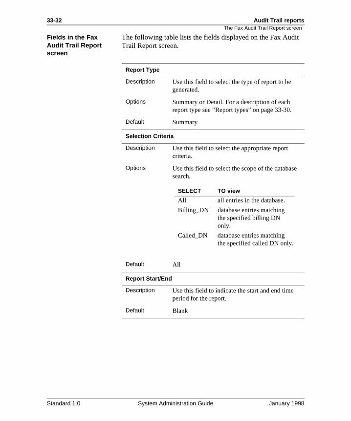
33-32 Audit Trail reports
t
The Fax Audit Trail Report screen
Fields in the Fax Audit Trail Report screen
The following table lists the fields displayed on the Fax AudiTrail Report screen.
Report Type
Description Use this field to select the type of report to be generated.
Options Summary or Detail. For a description of each report type see “Report types” on page 33-30.
Default Summary
Selection Criteria
Description Use this field to select the appropriate report criteria.
Options Use this field to select the scope of the databasesearch.
Default All
Report Start/End
Description Use this field to indicate the start and end time period for the report.
Default Blank
SELECT TO view
All all entries in the database.
Billing_DN database entries matching the specified billing DN only.
Called_DN database entries matching the specified called DN only.
Standard 1.0 System Administration Guide January 1998
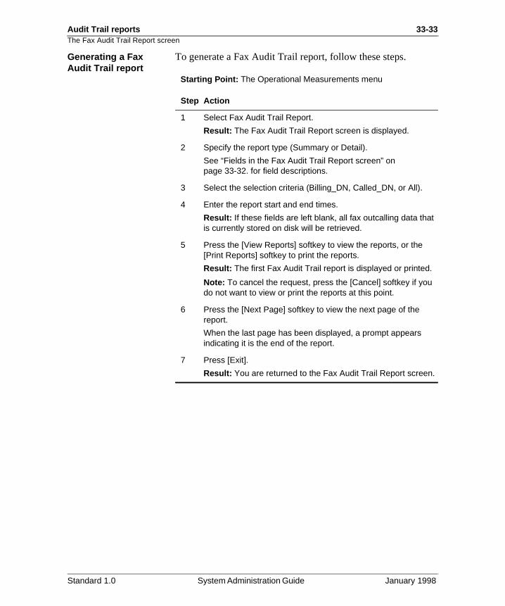
Audit Trail reports 33-33The Fax Audit Trail Report screen
Generating a Fax Audit Trail report
To generate a Fax Audit Trail report, follow these steps.
Starting Point: The Operational Measurements menu
Step Action
1 Select Fax Audit Trail Report.
Result: The Fax Audit Trail Report screen is displayed.
2 Specify the report type (Summary or Detail).
See “Fields in the Fax Audit Trail Report screen” on page 33-32. for field descriptions.
3 Select the selection criteria (Billing_DN, Called_DN, or All).
4 Enter the report start and end times.
Result: If these fields are left blank, all fax outcalling data that is currently stored on disk will be retrieved.
5 Press the [View Reports] softkey to view the reports, or the [Print Reports] softkey to print the reports.
Result: The first Fax Audit Trail report is displayed or printed.
Note: To cancel the request, press the [Cancel] softkey if you do not want to view or print the reports at this point.
6 Press the [Next Page] softkey to view the next page of the report.
When the last page has been displayed, a prompt appears indicating it is the end of the report.
7 Press [Exit].
Result: You are returned to the Fax Audit Trail Report screen.
Standard 1.0 System Administration Guide January 1998
33-34 Audit Trail reports
The Fax Audit Trail Report screenPrinting a Fax Audit Trail report
To print a Fax Audit Trail report, follow these steps.
Starting Point: The Operational Measurements menu
Step Action
1 Select Fax Audit Trail Report.
Result: The Fax Audit Trail Report appears.
2 Change the selection criteria as desired.
3 Ensure that the printer is online and has paper.
4 Press [Print Reports].
Result: A new set of softkeys is displayed: [Cancel Printing] and [Continue Printing].
To cancel printing, press the [Cancel] softkey.
5 Press [Continue Printing] to print the report.
Result: The report is printed and you are returned to the Operational Measurements menu.
Note: If you selected [Continue Printing], a [Cancel] softkey is displayed that can be used to cancel printing once printing has started.
Standard 1.0 System Administration Guide January 1998
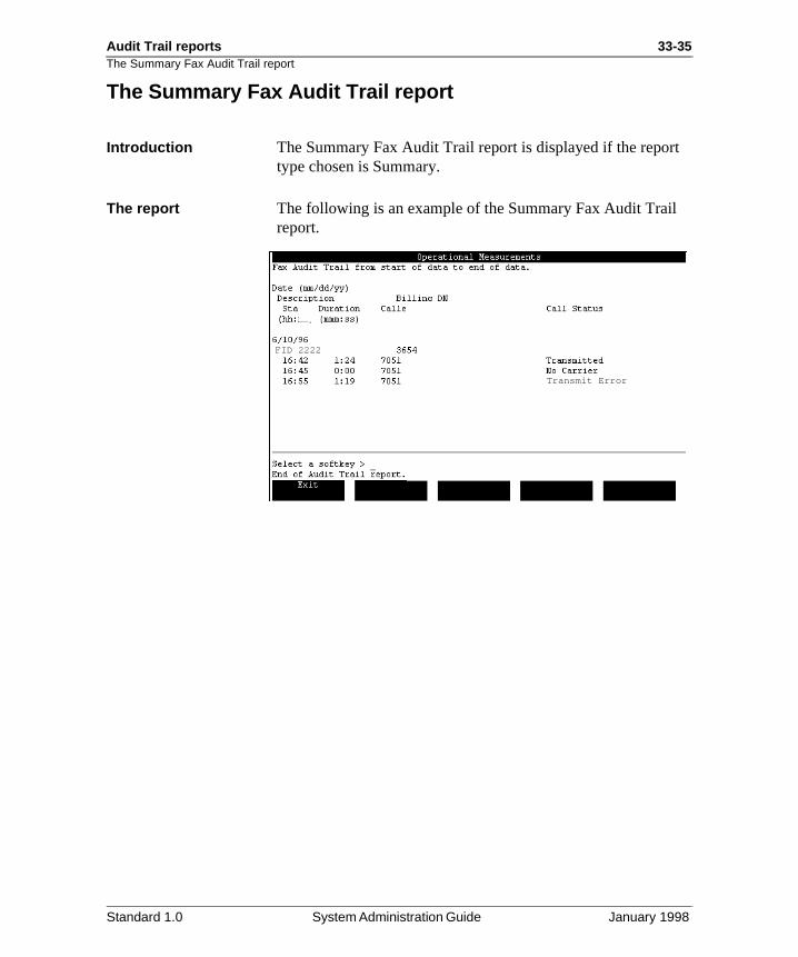
Audit Trail reports 33-35The Summary Fax Audit Trail report
t
The Summary Fax Audit Trail report
Introduction The Summary Fax Audit Trail report is displayed if the reportype chosen is Summary.
The report The following is an example of the Summary Fax Audit Trailreport.
FID 2222
Transmit Error
Standard 1.0 System Administration Guide January 1998
33-36 Audit Trail reports
re
not
by a
Fields in the Summary Fax Audit Trail report screen
Fields in the Summary Fax Audit Trail report screen
Introduction The Summary Fax Audit Trail report displays the following information.
Date This indicates the date the call was made.
Description This is a description of the application.
Billing DN This indicates the billing DN that originated the call.
Start (hh:mm) This indicates the time at which the call was made.
Duration (mm:ss) This indicates the length of the call in minutes and seconds.
Called DN This indicates the destination DN for the fax delivery.
Call Status This field displays the result of the call. The allowed values aas follows.
TransmittedThis state indicates that fax transmission was completed without error.
Transmit ErrorThis state indicates that the fax transmission started but wascompleted successfully.
No CarrierThis state indicates that the fax transmission was not startedbecause the call was not answered, or was answered but notcompatible fax device.
Standard 1.0 System Administration Guide January 1998
Audit Trail reports 33-37Analyzing the Summary Fax Audit Trail report
t to
ity il,
Analyzing the Summary Fax Audit Trail report
Description This report lists each fax callback call attempt. Use this repordetermine which fax delivery attempts are causing the high retry counts and failures that were detected by the Fax Activreport. To explore the cause of the problems in greater detarun the Detail Fax Audit Trail report.
Standard 1.0 System Administration Guide January 1998
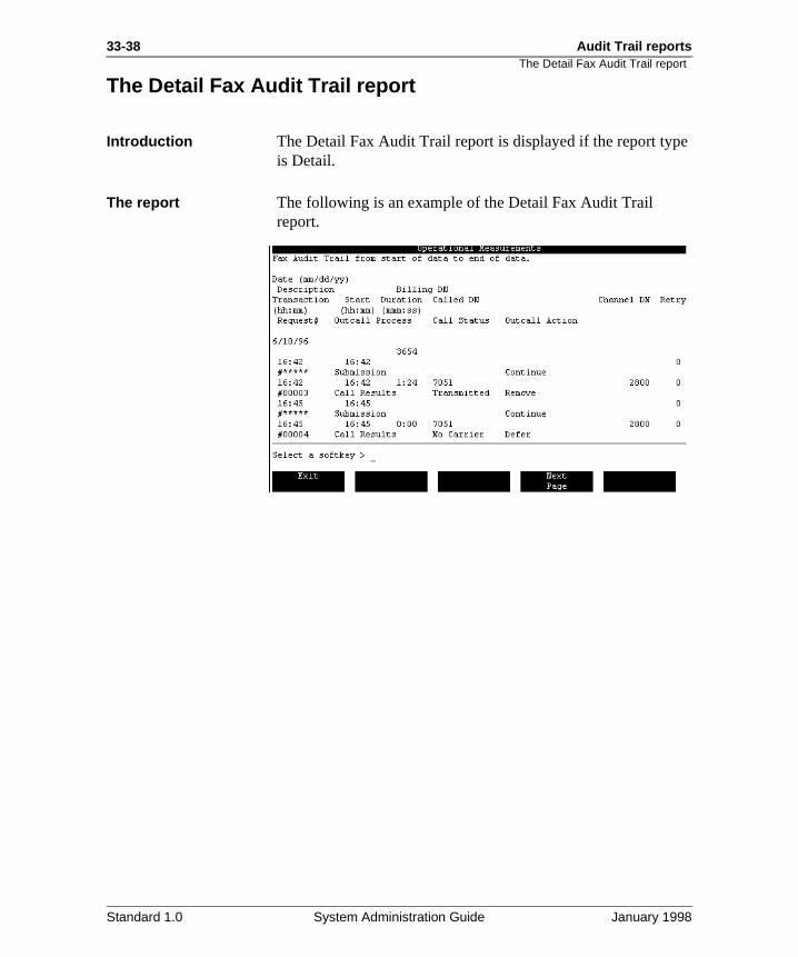
33-38 Audit Trail reports
e
The Detail Fax Audit Trail report
The Detail Fax Audit Trail report
Introduction The Detail Fax Audit Trail report is displayed if the report typis Detail.
The report The following is an example of the Detail Fax Audit Trail report.
Standard 1.0 System Administration Guide January 1998
Audit Trail reports 33-39Fields in the Detail Fax Audit Trail report screen
rt,
e.
e ed.
ted
or
Fields in the Detail Fax Audit Trail report screen
Introduction In addition to the information displayed in the summary repothe detailed report contains the following information fields.
Transaction (hh:mm) This is the time at which the delivery should have taken plac
Start (hh:mm) This is the time at which the current outcall process started.
Duration (mm:ss) This is the length of the call.
Called DN This is the destination DN for the fax delivery.
Channel DN This is the DN that was used to originate the call.
Retry This is the number of retries that were made at the time of thattempt. This field increments by one each time a DN is retri
Request # This is the number of the transaction request.
Outcall Process This is the type of audit trail entry. This could be one of the following.
Submission This type indicates that a request has been made for an Outcalling service.
Instead of Submission you may also see Recovery.
Recovery This type indicates that faxes for outcalling have been detecand submitted after a system reboot.
Validation This type indicates a checking process just before a call wasis made.
Standard 1.0 System Administration Guide January 1998
33-40 Audit Trail reports
out
not
ot by
al
ered
ly the e
ot If a le.)
. e
Fields in the Detail Fax Audit Trail report screen
Outcall Process (cont’d)
Call ResultsThis type indicates information regarding the Call Status andOutcall Action in the adjacent fields.
Call Status This field indicates the status of the call attempt. The possibilities are as follows.
Transmitted This state indicates that the fax transmission completed witherror.
Transmission ErrorThis state indicates that the fax transmission was started butsuccessfully completed.
No Carrier This state indicates that the fax transmission was not startedbecause the call was not answered, or was answered, but na compatible fax device.
Illegal Window This state indicates that the fax became stale during an illegtime window and could not be delivered. (The stale date parameter defaults to 36 hours. If a message cannot be delivwithin this time, a message becomes stale.)
Stale Date This state indicates that the fax was not delivered immediate(either because it was sent during a restricted time period, orfax was not transmitted and was, therefore, rescheduled). Thfax became stale during a permitted time period and could nbe delivered. (The stale date parameter defaults to 36 hours.fax cannot be delivered within this time, the fax becomes sta
Bad Called DN This state indicates that during an outcall, the target DN wasdialed, and a bad called DN was detected by the local switch(In other words, the target DN is invalid for some reason.) Thcallback fax is not delivered and is removed.
Standard 1.0 System Administration Guide January 1998
Audit Trail reports 33-41Fields in the Detail Fax Audit Trail report screen
use e to
o
he mpt he
d a
ing
d
Call Status (cont’d) Resource Delay This state indicates that the outcall was not completed becathe line on which the call was to be made was taken away duan incoming call that was given priority. The outgoing call is retried on a different channel. If this is a persistent problem, reserve channels for fax callback deliveries and make sure nACD queues terminate on them.
IncompleteThis state indicates that the outcall could not be completed. Tcall attempt will be treated as a busy attempt, and a retry attewill be scheduled if the busy and no answer retries have notbeen exhausted. If there is an accompanying SEER, follow taction described in the Maintenance Messages (SEERs) Reference Manual (NTP 555-7001-510).
Outcall Action This field indicates the action performed on the request. Thepossibilities are as follows.
Continue This action indicates that the validation has been passed ancall attempt is to be made.
Remove, retry limit reached This action indicates that after the call, the retry was not rescheduled because the retry limit had been reached.
Remove This action indicates that the fax was successfully delivered.
Reset This action indicates that a problem was encountered retrievinformation. Requests will be discarded and recovered from disk.
Delayed 1 This action indicates that a channel on which to call out coulnot be obtained. Will retry later.
Standard 1.0 System Administration Guide January 1998
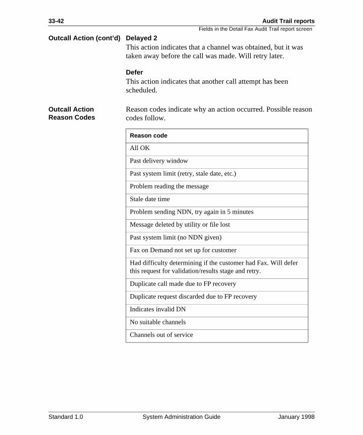
33-42 Audit Trail reports
son
Fields in the Detail Fax Audit Trail report screen
Outcall Action (cont’d) Delayed 2 This action indicates that a channel was obtained, but it wastaken away before the call was made. Will retry later.
Defer This action indicates that another call attempt has been scheduled.
Outcall Action Reason Codes
Reason codes indicate why an action occurred. Possible reacodes follow.
Reason code
All OK
Past delivery window
Past system limit (retry, stale date, etc.)
Problem reading the message
Stale date time
Problem sending NDN, try again in 5 minutes
Message deleted by utility or file lost
Past system limit (no NDN given)
Fax on Demand not set up for customer
Had difficulty determining if the customer had Fax. Will defer this request for validation/results stage and retry.
Duplicate call made due to FP recovery
Duplicate request discarded due to FP recovery
Indicates invalid DN
No suitable channels
Channels out of service
Standard 1.0 System Administration Guide January 1998
Audit Trail reports 33-43Analyzing the Detail Fax Audit Trail report
and ual em
ods.
x
y ays
the ail
e
ok k
the
Analyzing the Detail Fax Audit Trail report
Introduction Use this information to analyze the Detail Fax Audit Trail report data.
Call Back Status Check Call Back Status for the failing fax deliveries. For incomplete calls, check to see if a SEER has been produced,refer to the Maintenance Messages (SEERs) Reference Man (NTP 555-7001-510) for information on solving the problem.For call transmission failure due to resource delay, your systmay need more multimedia channels. If faxes are becomingstale (faxes are not being sent before the maximum time fordelivery attempts expires), check the time windows to make sure that the faxes are not being sent during illegal time peri
Fax delivery fails on Bad Called DN
If the fax delivery attempt fails on Bad Called DN, dial the faphone number to find out if the number is operational. The caller may have provided a wrong number.
Call Back Action field Check the Call Back Action field for delays (Delay 1 and Dela2). Delays indicate busy channels. If these problems with delpersist, your system may need more multimedia channels.
Recurring fax deliveries on the same channel
Recurring fax delivery failures on the same channel may indicate problems with the channel hardware. To determine channel number from the Channel DN, go to the Meridian MAdministrative screen and view the Channel Allocation Table(CAT):
• If the system is connected to a Meridian 1 system, look under the SCN field and find Channel DN, then look up thchannel number.
• If the system is connected to a non-Meridian 1 switch, lounder the Channel DN field for the Channel DN, then looup the channel number.
Run the Channel Problem Identification Report to see if the channel has unusual traffic patterns. You may need to checkDSP hardware and switch terminal number status as well.
Standard 1.0 System Administration Guide January 1998

33-44 Audit Trail reportsAnalyzing the Detail Fax Audit Trail report
Standard 1.0 System Administration Guide January 1998
Chapter 34
Bulk provisioning
In this chapter
Overview 34-2
Section A: Introduction to bulk provisioning 34-3
Section B: Working with bulk provisioning data sets 34-9
Section C: Transferring bulk provisioning data onto tape 34-27
Section D: Provisioning data into a Meridian Mail system 34-33
34-2 Bulk provisioning Overview
ail
es
ta
ta
Overview
Introduction This chapter contains information on the bulk provisioning feature of Meridian Mail 12. Bulk provisioning allows administrators or distributors to copy voice services such asmenus, announcements, and fax items from one Meridian Msystem to another.
Section A: Introduction to bulk provisioning, provides a conceptual overview of bulk provisioning and its uses.
Section B: Working with bulk provisioning data sets, discussbulk provisioning data sets, including the procedure to createthem. As well, procedures for deleting, viewing, and printingdata sets are included.
Section C: Transferring bulk provisioning data onto tape, describes the procedure for copying the bulk provisioning dasets onto tape.
Section D: Provisioning data into a Meridian Mail system, provides information about provisioning bulk provisioning dasets to the Meridian Mail system.
Standard 1.0 System Administration Guide January 1998
Bulk provisioning 34-3
Section A: Introduction to bulk provisioning
In this section
Overview 34-4
What is bulk provisioning? 34-5
Using bulk provisioning 34-6
Standard 1.0 System Administration Guide January 1998
34-4 Bulk provisioning Overview
Overview
Introduction This section includes information on the concept of bulk provisioning—what it is and how it can be used. Included areexamples and operational considerations.
Standard 1.0 System Administration Guide January 1998
Bulk provisioning 34-5What is bulk provisioning?
.
d to
’s
n
gs
nd the
the
ion te s
What is bulk provisioning?
Introduction This topic describes and gives examples of bulk provisioning
Description Bulk provisioning is a feature that allows the administrator tocollect voice service, VSDN, and local user information into data sets, copy them to tape, and have the information copieother Meridian Mail systems.
Bulk provisioning enables selective distribution of one systemVSDNs and services on another system.
Example The XYZ Company head office has decided to open a new location in the western region. The new site is obtaining its owMeridian Mail system. The company’s president wants his customers in the western region to receive the same greetinand services provided at head office.
In order to provide the same services (for example, menus aannouncements) to the new site as they have at head office,administrator uses bulk provisioning to collect the required services onto tape. The administrator then sends the tape towestern region site. At the new site, the administrator provisions the new system with the information on the tape.
If both sites have Meridian Mail Networking installed, the administrator can use bulk provisioning to collect local user information, copy it onto a tape and send it to the western regsite where it is added as remote users. This allows the remousers to have their names played in their own voices, duringmessage compose and when name and dial addressed. Thifeature helps make the network appear transparent.
Standard 1.0 System Administration Guide January 1998
34-6 Bulk provisioning Using bulk provisioning
il
es
n
Ns ail up
r
es in
the r e re
Using bulk provisioning
Introduction This topic describes uses of the bulk provisioning feature.
System setup Bulk provisioning can be used to initialize a new Meridian Masystem. Selected or all services as well as VSDNs can be collected from the “master” Meridian Mail system into data sets, copied to tape, and provisioned to new Meridian Mail systems.
This allows the administrator to ensure that all services, including menus, announcements, fax items, time of day controllers, and all other services defined using Voice ServicAdministration (VSA) are distributed and installed on all Meridian Mail systems.
Once the system is set up, the administrator can also save periodic updates to tape and provision them at other MeridiaMail systems. In this way, a group of Meridian Mail systems can always be kept up-to-date with the same services and VSDNs.
Multi-customer administration
Bulk provisioning can be used to copy services (but not VSDor users) between customer groups on the same Meridian Msystem. This could save time and reduce errors when settingcommon services.
Remote user administration
Bulk provisioning allows the administrator to add remote useinformation to systems with Meridian Mail networking all at once rather than one user at a time. The users’ spoken namtheir own voices are included so that the administrator is no longer required to record them.
The users’ organization directory entries are copied to tape; administrator uses this tape to provision the users on anotheMeridian Mail system in the network. If the networking featuris installed, local users may be copied to tape. NMS users aconsidered local users and may be included on the tape.
Standard 1.0 System Administration Guide January 1998
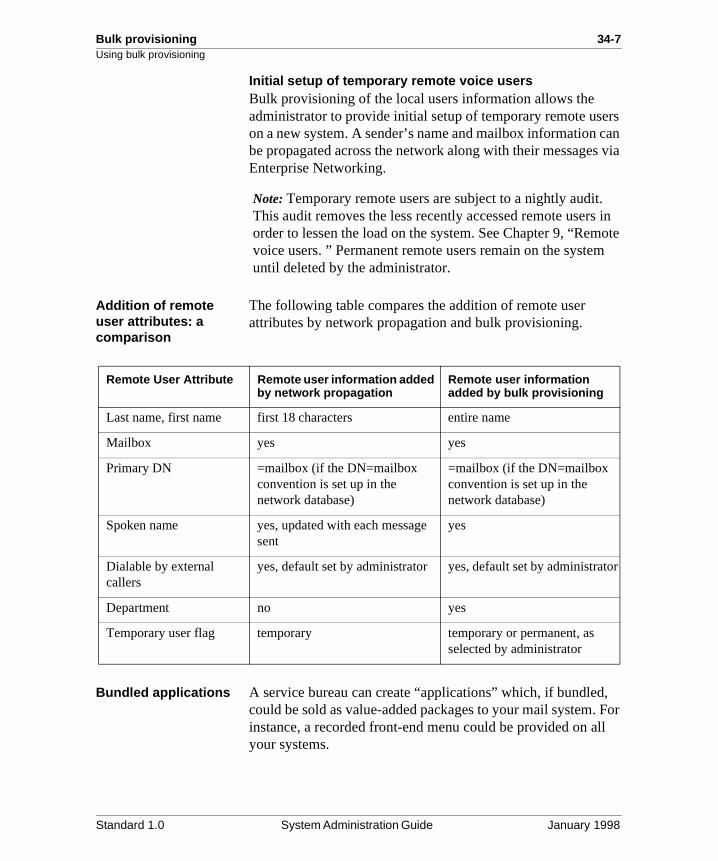
Bulk provisioning 34-7Using bulk provisioning
rs can via
in ote
m
, For ll
tor
Initial setup of temporary remote voice usersBulk provisioning of the local users information allows the administrator to provide initial setup of temporary remote useon a new system. A sender’s name and mailbox information be propagated across the network along with their messagesEnterprise Networking.
Note: Temporary remote users are subject to a nightly audit.This audit removes the less recently accessed remote usersorder to lessen the load on the system. See Chapter 9, “Remvoice users. ” Permanent remote users remain on the systeuntil deleted by the administrator.
Addition of remote user attributes: a comparison
The following table compares the addition of remote user attributes by network propagation and bulk provisioning.
Bundled applications A service bureau can create “applications” which, if bundledcould be sold as value-added packages to your mail system.instance, a recorded front-end menu could be provided on ayour systems.
Remote User Attribute Remote user information added by network propagation
Remote user information added by bulk provisioning
Last name, first name first 18 characters entire name
Mailbox yes yes
Primary DN =mailbox (if the DN=mailbox convention is set up in the network database)
=mailbox (if the DN=mailbox convention is set up in the network database)
Spoken name yes, updated with each message sent
yes
Dialable by external callers
yes, default set by administrator yes, default set by administra
Department no yes
Temporary user flag temporary temporary or permanent, as selected by administrator
Standard 1.0 System Administration Guide January 1998

34-8 Bulk provisioning Using bulk provisioning
Standard 1.0 System Administration Guide January 1998
Bulk provisioning 34-9
Section B: Working with bulk provisioning data sets
In this section
Overview 34-10
Assembling bulk provisioning data sets 34-11
Creating and modifying bulk provisioning data sets 34-14
Viewing and printing bulk provisioning data sets 34-21
Deleting bulk provisioning data sets 34-25
Standard 1.0 System Administration Guide January 1998
34-10 Bulk provisioning Overview
d
Overview
Introduction This section includes information that you need to create anmodify bulk provisioning data sets. Also included are instructions on viewing, printing, and deleting data sets.
Standard 1.0 System Administration Guide January 1998
Bulk provisioning 34-11Assembling bulk provisioning data sets
k ist.
o tor
a
t
get
a
n s ze
y
set
4
n be nd
Assembling bulk provisioning data sets
Introduction This section provides information required to create new bulprovisioning data sets and modify data sets that currently ex
Concept of bulk provisioning data sets
Bulk provisioning provides the administrator with the ability tgroup sets of provisioning data into a catalog. The administracan select services, VSDNs, and local user information for provisioning to other systems. These selections are saved inbulk provisioning data set and later copied to tape.
These data sets are the starting point for bulk provisioning. Athis point, the tape is created from a data set and is sent to another site where the contents can be duplicated on the tarMeridian Mail system.
The administrator can create up to 100 bulk provisioning datsets. The data sets can be stored for future use, and can bemodified if required.
Using Wildcards in the Provisioning Data
Using wildcards can be useful when specifying multimedia services or VSDNs. By using wildcards, the administrator cacollect much more information than the number of input fieldwould allow. Also, wildcards provide a means to help organithe items in the data set.
The wildcards available for use are the organization directorwildcards:
• “+” to represent any number of characters
• “_” to represent exactly one character
ExampleThe administrator in an automotive company can group oneof multimedia services (faxes, menus, announcements) referring to new products with service IDs beginning with thecharacters 11 (for example, 110001, 110002, 110003, 11000and so on). By using a wildcard character, these services careferred to as 11+. Another set of services relating to parts asupport could be referred to as 12+. This allows the
Standard 1.0 System Administration Guide January 1998
34-12 Bulk provisioning Assembling bulk provisioning data sets
ctly are
ices -of- ain
t
te
t rea
administrator to choose specific groupings of services for various sites.
Important considerations
The administrator must be aware of the following important considerations before beginning to collect data for the provisioning data sets.
Support requirementsThe administrator must ensure that the target system is correset up with support needed for the services and VSDNs thatbeing bulk provisioned. Included in these considerations arefeatures, hours, networking sites, DNs or TNs, switch connectivity, and system restriction/permission lists.
DependenciesThe administrator must ensure that multimedia services provisioned to a target system do not have references to servthat do not exist on the system. For instance, menus or timeday controllers typically refer to other services that should beincluded in the data set as well. VSDNs may also require certservices in order to function properly. Bulk provisioning doesnot automatically resolve these dependencies. This is the administrator’s responsibility.
Hardware-specific informationHardware-specific information is not propagated to the targesystem. This information includes
• port names
• link information
• network database information relating to local and remosites
• the hardware database
Restriction/permission indexesRestriction and permission indexes associated with specific services on the source system are brought over to the targesystem. The administrator must take care to ensure that theindexes make sense when preconfiguring systems across acodes on the destination system.
Standard 1.0 System Administration Guide January 1998
Bulk provisioning 34-13Assembling bulk provisioning data sets
he his
Ns
ng et
Dialing plan comparisonThe system does not do a comparison check of the DNs of tsource system against the dialing plan of the target system. Taffects
• VSDNs (such as menus, announcements, and time-of-day controllers)
• billing DNs
• revert DNs
• fax confirmation DNs
• attendant DNs
Remapping capabilityNo capability is provided for remapping of DNs or various service IDs. The target system will have exactly the same Dand service IDs as the source system.
The administrator should make sure that all revert DNs and service IDs make sense on the target system before beginnithe bulk provisioning. If required, the administrator of the targsystem can use the MMI to correct DNs and service IDs of provisioned services.
System and customer profilesInformation kept in the system or customer profiles is not transferred during bulk provisioning.
Standard 1.0 System Administration Guide January 1998
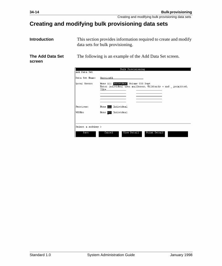
34-14 Bulk provisioning Creating and modifying bulk provisioning data sets
ify
Creating and modifying bulk provisioning data sets
Introduction This section provides information required to create and moddata sets for bulk provisioning.
The Add Data Set screen
The following is an example of the Add Data Set screen.
Standard 1.0 System Administration Guide January 1998
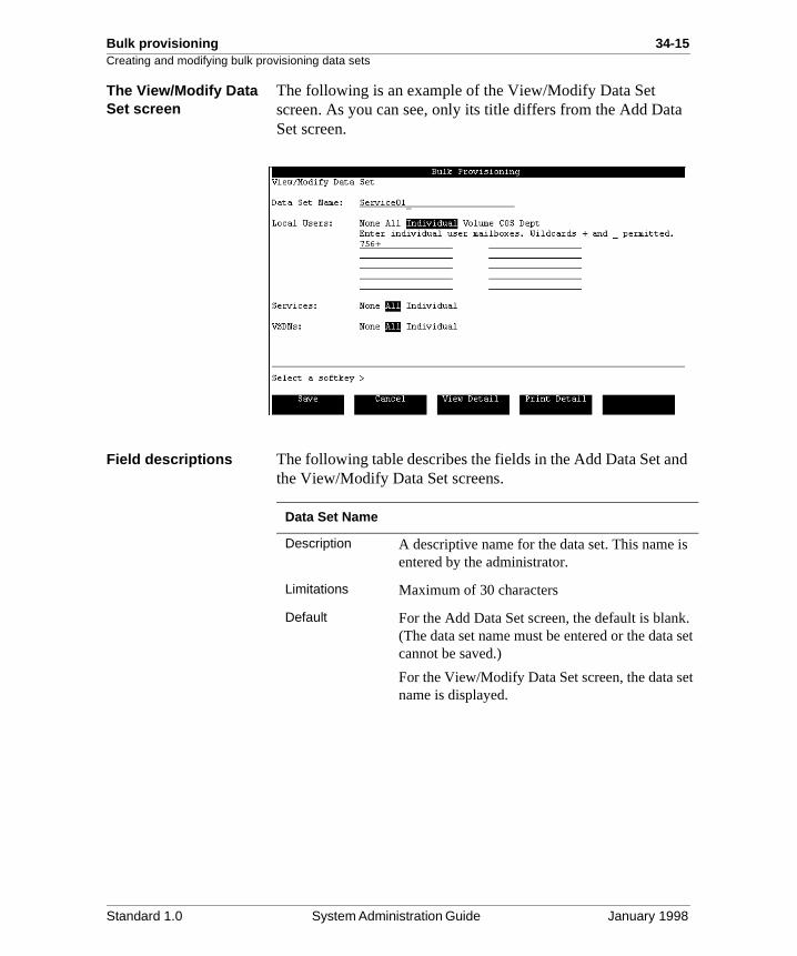
Bulk provisioning 34-15Creating and modifying bulk provisioning data sets
ta
nd
is
k. set
et
The View/Modify Data Set screen
The following is an example of the View/Modify Data Set screen. As you can see, only its title differs from the Add DaSet screen.
Field descriptions The following table describes the fields in the Add Data Set athe View/Modify Data Set screens.
Data Set Name
Description A descriptive name for the data set. This name entered by the administrator.
Limitations Maximum of 30 characters
Default For the Add Data Set screen, the default is blan(The data set name must be entered or the datacannot be saved.)
For the View/Modify Data Set screen, the data sname is displayed.
Standard 1.0 System Administration Guide January 1998
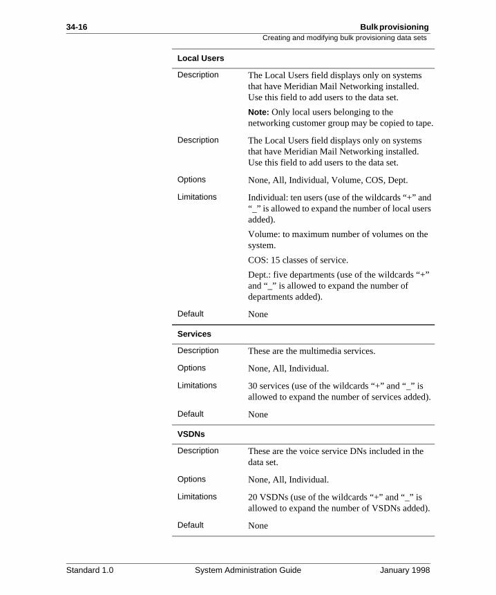
34-16 Bulk provisioning Creating and modifying bulk provisioning data sets
pe.
d rs
”
d).
).
Local Users
Description The Local Users field displays only on systemsthat have Meridian Mail Networking installed. Use this field to add users to the data set.
Note: Only local users belonging to the networking customer group may be copied to ta
Description The Local Users field displays only on systemsthat have Meridian Mail Networking installed. Use this field to add users to the data set.
Options None, All, Individual, Volume, COS, Dept.
Limitations Individual: ten users (use of the wildcards “+” an“_” is allowed to expand the number of local useadded).
Volume: to maximum number of volumes on thesystem.
COS: 15 classes of service.
Dept.: five departments (use of the wildcards “+and “_” is allowed to expand the number of departments added).
Default None
Services
Description These are the multimedia services.
Options None, All, Individual.
Limitations 30 services (use of the wildcards “+” and “_” is allowed to expand the number of services adde
Default None
VSDNs
Description These are the voice service DNs included in thedata set.
Options None, All, Individual.
Limitations 20 VSDNs (use of the wildcards “+” and “_” is allowed to expand the number of VSDNs added
Default None
Standard 1.0 System Administration Guide January 1998
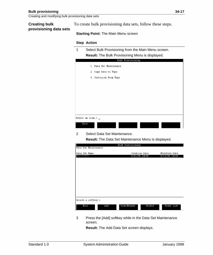
Bulk provisioning 34-17Creating and modifying bulk provisioning data sets
Creating bulk provisioning data sets
To create bulk provisioning data sets, follow these steps.
Starting Point: The Main Menu screen
Step Action
1 Select Bulk Provisioning from the Main Menu screen.
Result: The Bulk Provisioning Menu is displayed.
2 Select Data Set Maintenance.
Result: The Data Set Maintenance Menu is displayed.
3 Press the [Add] softkey while in the Data Set Maintenance screen.
Result: The Add Data Set screen displays.
Service01
Standard 1.0 System Administration Guide January 1998
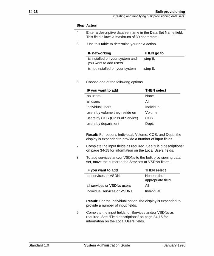
34-18 Bulk provisioning Creating and modifying bulk provisioning data sets
4 Enter a descriptive data set name in the Data Set Name field. This field allows a maximum of 30 characters.
5 Use this table to determine your next action.
6 Choose one of the following options.
Result: For options Individual, Volume, COS, and Dept., the display is expanded to provide a number of input fields.
7 Complete the input fields as required. See “Field descriptions” on page 34-15 for information on the Local Users fields.
8 To add services and/or VSDNs to the bulk provisioning data set, move the cursor to the Services or VSDNs fields.
Result: For the Individual option, the display is expanded to provide a number of input fields.
9 Complete the input fields for Services and/or VSDNs as required. See “Field descriptions” on page 34-15 for information on the Local Users fields.
Step Action
IF networking THEN go to
is installed on your system and you want to add users
step 6.
is not installed on your system step 8.
IF you want to add THEN select
no users None
all users All
individual users Individual
users by volume they reside on Volume
users by COS (Class of Service) COS
users by department Dept.
IF you want to add THEN select
no services or VSDNs None in the appropriate field
all services or VSDNs users All
individual services or VSDNs Individual
Standard 1.0 System Administration Guide January 1998
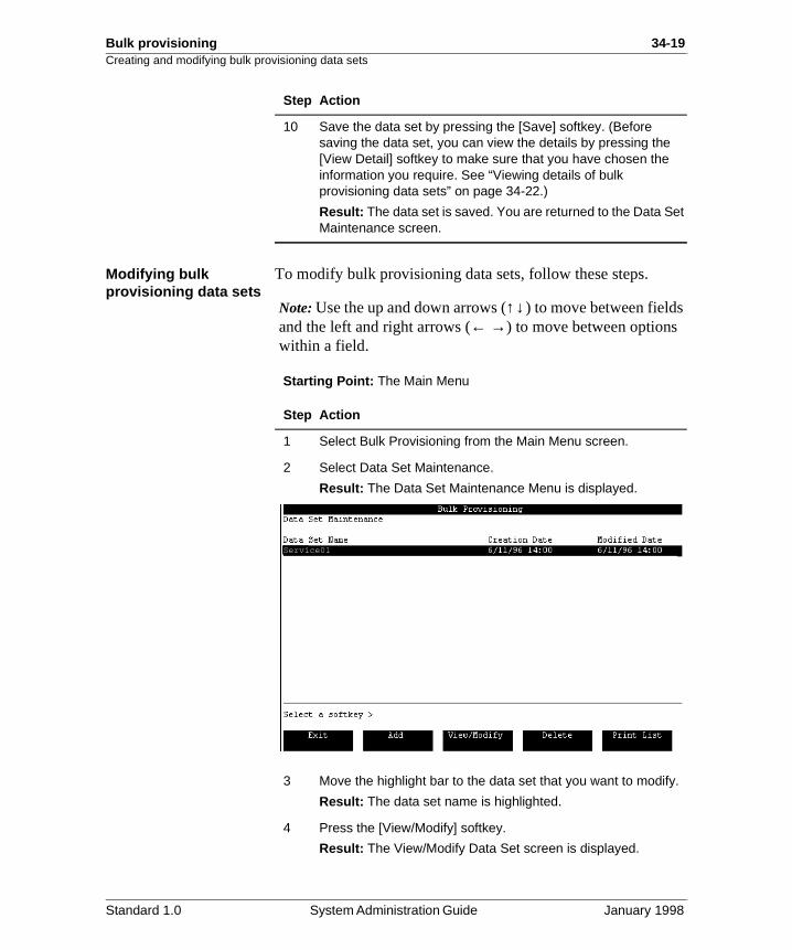
Bulk provisioning 34-19Creating and modifying bulk provisioning data sets
Modifying bulk provisioning data sets
To modify bulk provisioning data sets, follow these steps.
Note: Use the up and down arrows (↑↓) to move between fields and the left and right arrows (← →) to move between options within a field.
Starting Point: The Main Menu
10 Save the data set by pressing the [Save] softkey. (Before saving the data set, you can view the details by pressing the [View Detail] softkey to make sure that you have chosen the information you require. See “Viewing details of bulk provisioning data sets” on page 34-22.)
Result: The data set is saved. You are returned to the Data Set Maintenance screen.
Step Action
Step Action
1 Select Bulk Provisioning from the Main Menu screen.
2 Select Data Set Maintenance.
Result: The Data Set Maintenance Menu is displayed.
3 Move the highlight bar to the data set that you want to modify.
Result: The data set name is highlighted.
4 Press the [View/Modify] softkey.
Result: The View/Modify Data Set screen is displayed.
Service01
Standard 1.0 System Administration Guide January 1998
34-20 Bulk provisioning Creating and modifying bulk provisioning data sets
5 Change the input fields as required. See “Field descriptions” on page 34-15 for information on each of the fields.
6 Save the data set by pressing the [Save] softkey. (Before saving the data set, you can view the details by pressing the [View Detail] softkey to make sure that you have chosen the information you require. See “Viewing details of bulk provisioning data sets” on page 34-22.)
Result: The data set is saved. You are returned to the Data Set Maintenance screen.
Step Action
Standard 1.0 System Administration Guide January 1998
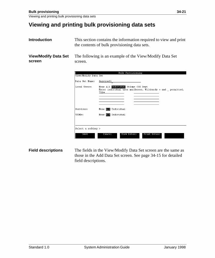
Bulk provisioning 34-21Viewing and printing bulk provisioning data sets
int
as ed
Viewing and printing bulk provisioning data sets
Introduction This section contains the information required to view and prthe contents of bulk provisioning data sets.
View/Modify Data Set screen
The following is an example of the View/Modify Data Set screen.
Field descriptions The fields in the View/Modify Data Set screen are the same those in the Add Data Set screen. See page 34-15 for detailfield descriptions.
Standard 1.0 System Administration Guide January 1998
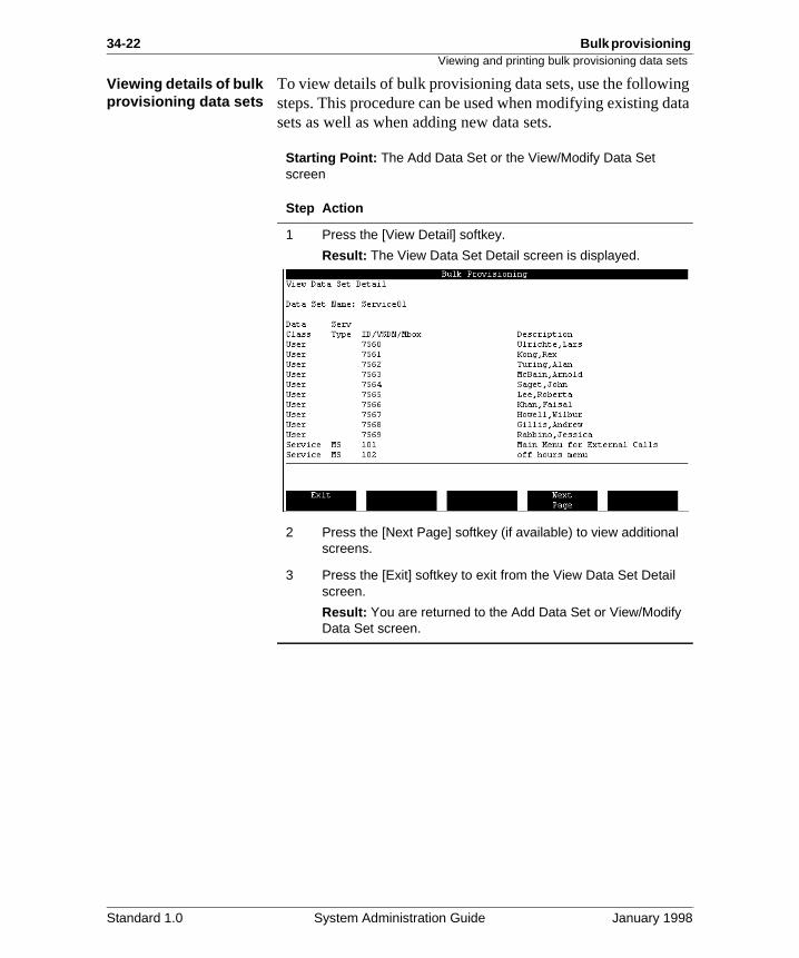
34-22 Bulk provisioning Viewing and printing bulk provisioning data sets
g ata
Viewing details of bulk provisioning data sets
To view details of bulk provisioning data sets, use the followinsteps. This procedure can be used when modifying existing dsets as well as when adding new data sets.
Starting Point: The Add Data Set or the View/Modify Data Set screen
Step Action
1 Press the [View Detail] softkey.
Result: The View Data Set Detail screen is displayed.
2 Press the [Next Page] softkey (if available) to view additional screens.
3 Press the [Exit] softkey to exit from the View Data Set Detail screen.
Result: You are returned to the Add Data Set or View/Modify Data Set screen.
Standard 1.0 System Administration Guide January 1998
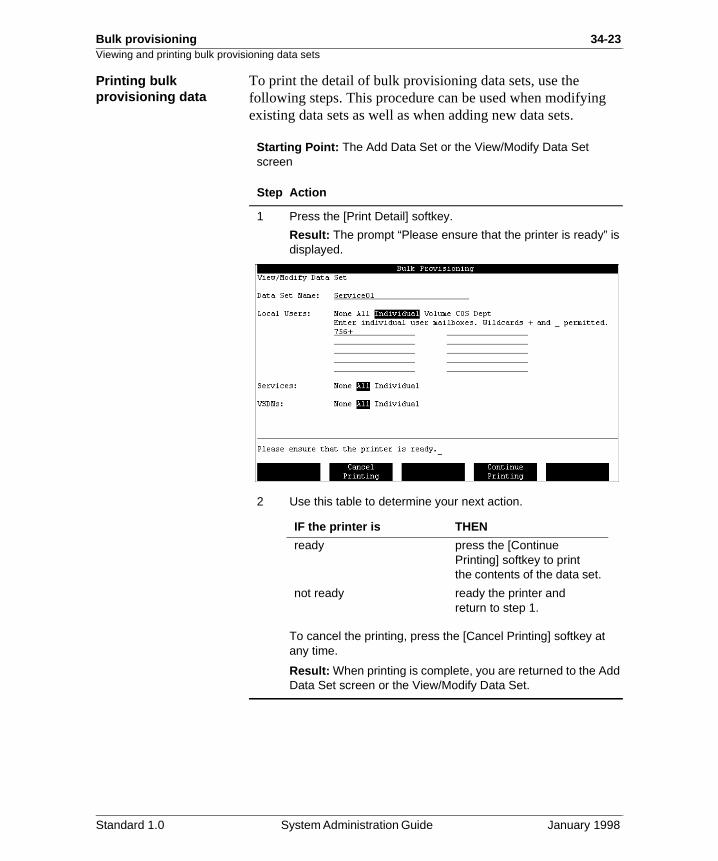
Bulk provisioning 34-23Viewing and printing bulk provisioning data sets
Printing bulk provisioning dataTo print the detail of bulk provisioning data sets, use the following steps. This procedure can be used when modifyingexisting data sets as well as when adding new data sets.
Starting Point: The Add Data Set or the View/Modify Data Set screen
Step Action
1 Press the [Print Detail] softkey.
Result: The prompt “Please ensure that the printer is ready” is displayed.
2 Use this table to determine your next action.
To cancel the printing, press the [Cancel Printing] softkey at any time.
Result: When printing is complete, you are returned to the Add Data Set screen or the View/Modify Data Set.
IF the printer is THEN
ready press the [Continue Printing] softkey to print the contents of the data set.
not ready ready the printer and return to step 1.
Standard 1.0 System Administration Guide January 1998
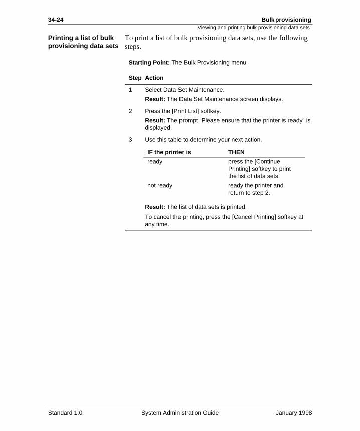
34-24 Bulk provisioning Viewing and printing bulk provisioning data sets
Printing a list of bulk provisioning data setsTo print a list of bulk provisioning data sets, use the followingsteps.
Starting Point: The Bulk Provisioning menu
Step Action
1 Select Data Set Maintenance.
Result: The Data Set Maintenance screen displays.
2 Press the [Print List] softkey.
Result: The prompt “Please ensure that the printer is ready” is displayed.
3 Use this table to determine your next action.
Result: The list of data sets is printed.
To cancel the printing, press the [Cancel Printing] softkey at any time.
IF the printer is THEN
ready press the [Continue Printing] softkey to print the list of data sets.
not ready ready the printer and return to step 2.
Standard 1.0 System Administration Guide January 1998
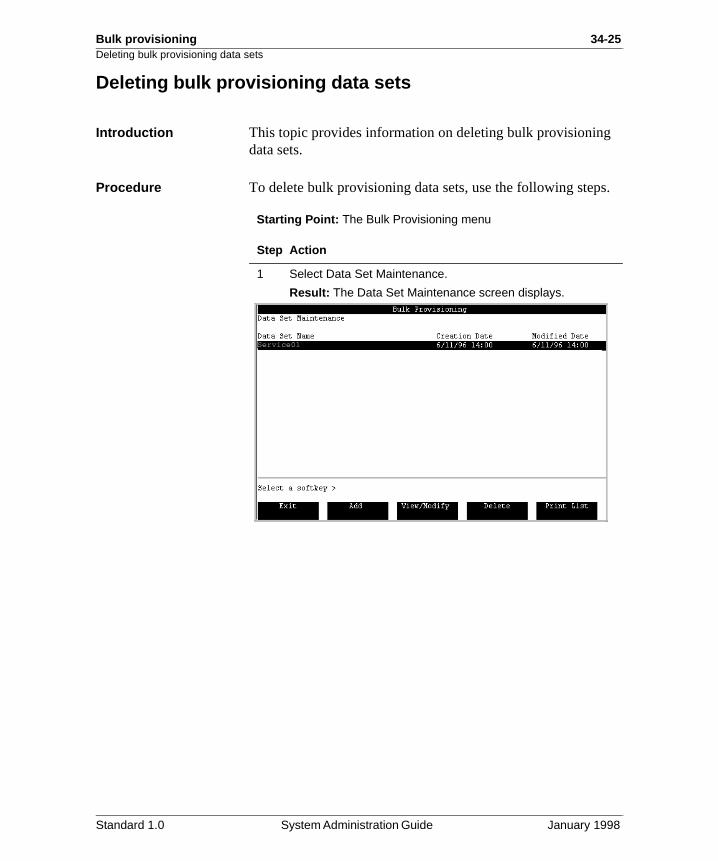
Bulk provisioning 34-25Deleting bulk provisioning data sets
s.
Deleting bulk provisioning data sets
Introduction This topic provides information on deleting bulk provisioningdata sets.
Procedure To delete bulk provisioning data sets, use the following step
Starting Point: The Bulk Provisioning menu
Step Action
1 Select Data Set Maintenance.
Result: The Data Set Maintenance screen displays.
Service01
Standard 1.0 System Administration Guide January 1998
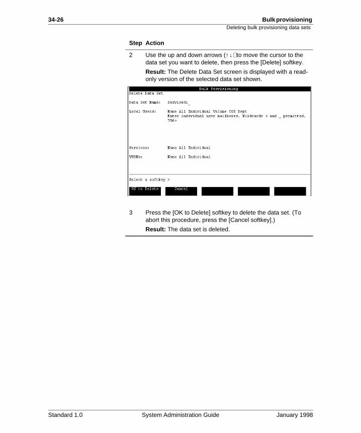
34-26 Bulk provisioning Deleting bulk provisioning data sets
2 Use the up and down arrows (↑↓) to move the cursor to the data set you want to delete, then press the [Delete] softkey.
Result: The Delete Data Set screen is displayed with a read-only version of the selected data set shown.
3 Press the [OK to Delete] softkey to delete the data set. (To abort this procedure, press the [Cancel softkey].)
Result: The data set is deleted.
Step Action
Standard 1.0 System Administration Guide January 1998
Bulk provisioning 34-27
Section C: Transferring bulk provisioning data onto tape
In this section
Overview 34-28
Copying provisioning data sets onto tape 34-29
Standard 1.0 System Administration Guide January 1998
34-28 Bulk provisioning Overview
of in
Overview
Introduction This section provides the procedure for copying bulk provisioning data sets onto tape. Also included is a diagram the Copy Data to Tape screen and a description of the fieldsthe screen.
Standard 1.0 System Administration Guide January 1998
Bulk provisioning 34-29Copying provisioning data sets onto tape
ve a
o
Copying provisioning data sets onto tape
Introduction This topic explains how to copy provisioning data sets onto tape. Before you begin the procedure, make sure that you hatape available and that you are able to load the tape when necessary. You must be logged in as system administrator tperform this procedure.
The Copy Data to Tape screen
This is an example of the initial Copy Data to Tape screen.
Standard 1.0 System Administration Guide January 1998
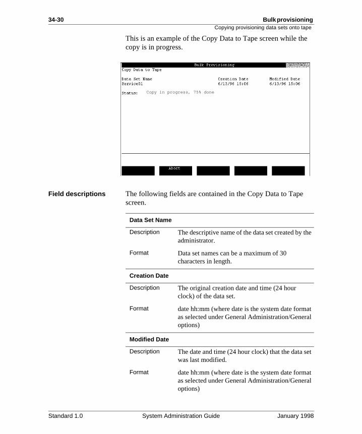
34-30 Bulk provisioning Copying provisioning data sets onto tape
e
he
at al
et
at al
This is an example of the Copy Data to Tape screen while thcopy is in progress.
Field descriptions The following fields are contained in the Copy Data to Tape screen.
Copy in progress, 75% done
Data Set Name
Description The descriptive name of the data set created by tadministrator.
Format Data set names can be a maximum of 30 characters in length.
Creation Date
Description The original creation date and time (24 hour clock) of the data set.
Format date hh:mm (where date is the system date formas selected under General Administration/Generoptions)
Modified Date
Description The date and time (24 hour clock) that the data swas last modified.
Format date hh:mm (where date is the system date formas selected under General Administration/Generoptions)
Standard 1.0 System Administration Guide January 1998
Bulk provisioning 34-31Copying provisioning data sets onto tape
.
n
er
Before you begin Ensure that the tape can be read by the destination system.Older systems have Archive tape drives which can only readDC150 and DC250 tapes.
Procedure To copy provisioning data onto tape, use the following steps
Starting Point: The Main Menu
Status
Description This field shows the status of the copy to tape. This field is viewable only after the tape has beeretensioned and the copy to tape begins.
Format Copy in progress, nn% done orCopy completed successfully
Note: The percentage done is based on the numbof items to be copied.
Step Action
1 Select Bulk Provisioning from the Main Menu and press <Return>.
Result: The Bulk Provisioning Menu is displayed.
2 Select Copy Data to Tape and press <Return>.
Result: The Copy Data to Tape screen is displayed.
3 Using the up and down arrow keys (↑↓), move the highlight bar to the data set you want to copy to tape.
Result: The data set is highlighted.
Note: Since one data set can be selected, only one data set can be copied at a time.
Standard 1.0 System Administration Guide January 1998
34-32 Bulk provisioning Copying provisioning data sets onto tape
Tip It is good practice to include a printout of the data set details(from Data Set Maintenance) along with the tape.4 Load a tape into the tape drive. Make sure that the tape is not write protected.
5 Press the [OK to Start Copy] softkey to begin the copy to tape.
Result: The message “The tape is retensioning” is displayed. Retensioning takes approximately four minutes. After the tape has retensioned, the data are copied to the tape. The Status field displays the status of the copy to tape during the process. Press the [Abort] softkey to cancel the copy to tape at any time.
When the copy to tape is complete, the message “Copy completed successfully” displays.
6 Use the [Exit] softkey to return to the Bulk Provisioning menu.
Step Action
IF the tape is THEN
in the tape drive in ready status
the copy to tape process begins.
not ready or write protected the message “Tape drive not ready” or “tape write protected” is displayed. Return to step 4.
Standard 1.0 System Administration Guide January 1998
Bulk provisioning 34-33
Section D: Provisioning data into a Meridian Mail system
In this section
Overview 34-34
Before you start 34-35
Provisioning data 34-37
Viewing and printing data conflicts 34-43
Standard 1.0 System Administration Guide January 1998
34-34 Bulk provisioning Overview
at
Overview
Introduction This section provides information on provisioning data sets thwere copied from one Meridian Mail system onto the currentMeridian Mail system.
Standard 1.0 System Administration Guide January 1998
Bulk provisioning 34-35Before you start
r
ing
to
is
Before you start
Introduction This section provides important information the administratorequires before beginning the provisioning of the bulk provisioning data on the target Meridian Mail system.
How the system responds to users during restore
When provisioning of a system is in progress or completes, services that are in use continue to use the previous version ofthe service as well as the previous set of prompts even afterprovisioning completes. The new services and prompts are available to users if they are first accessed after the provisioncompletes.
Potential conflicts between databases
Two types of conflicts, system level or data, may arise whenbulk provisioning data from one Meridian Mail system to another.
System level conflictsSystem level conflicts will cause provisioning to fail. To overcome a system level conflict, the administrator may haverestrict the choice of data to be provisioned.
System conflicts that cause provisioning to fail include the following:
• a feature is not installed
• an insufficient number of languages are available
• networking sites are not defined
Data conflictsData conflicts do not cause provisioning to fail but they can cause data to be overwritten. If a particular VSDN or service
CAUTION
Risk of data loss
Check for system level and data conflictsbefore proceeding with the bulk provisioning.Failure to do so may result in a loss of data.
Standard 1.0 System Administration Guide January 1998
34-36 Bulk provisioning Before you start
the
em mit the
defined on the bulk provisioning tape and is also defined on target Meridian Mail system, the target system data will be overwritten if provisioning continues. Provisioning can be continued or canceled if data conflicts exist.
Also, if there are more users on the tape than the target systhas room for, temporary users are added up to the system lionly. This may result in some users not being provisioned to target system.
Standard 1.0 System Administration Guide January 1998
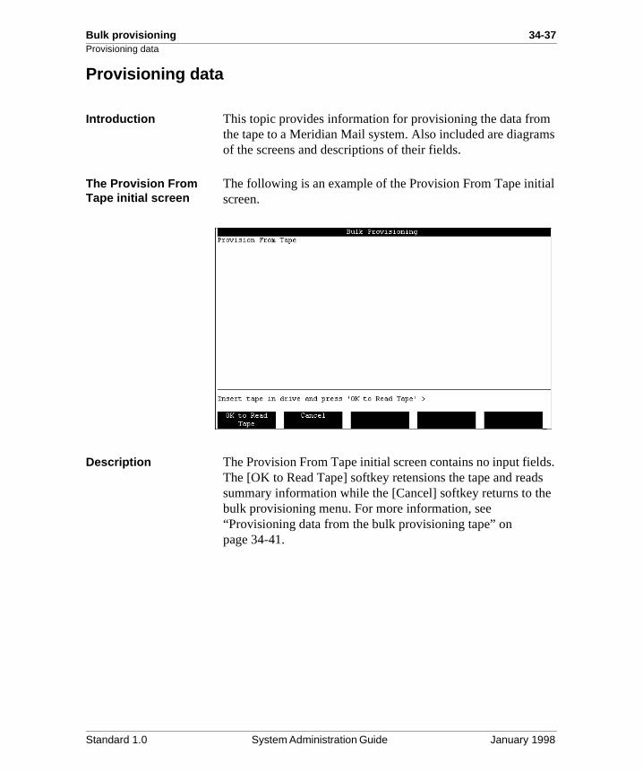
Bulk provisioning 34-37Provisioning data
ms
al
s. s e
Provisioning data
Introduction This topic provides information for provisioning the data fromthe tape to a Meridian Mail system. Also included are diagraof the screens and descriptions of their fields.
The Provision From Tape initial screen
The following is an example of the Provision From Tape initiscreen.
Description The Provision From Tape initial screen contains no input fieldThe [OK to Read Tape] softkey retensions the tape and readsummary information while the [Cancel] softkey returns to thbulk provisioning menu. For more information, see “Provisioning data from the bulk provisioning tape” on page 34-41.
Standard 1.0 System Administration Guide January 1998
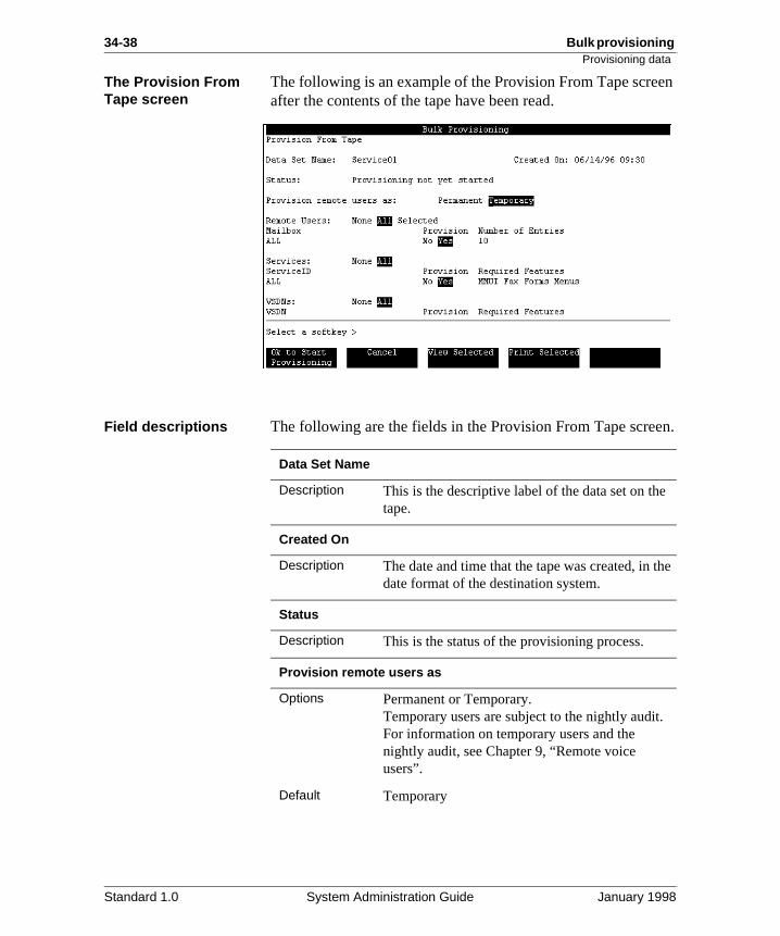
34-38 Bulk provisioning Provisioning data
en
n.
he
The Provision From Tape screen
The following is an example of the Provision From Tape screafter the contents of the tape have been read.
Field descriptions The following are the fields in the Provision From Tape scree
Data Set Name
Description This is the descriptive label of the data set on thetape.
Created On
Description The date and time that the tape was created, in tdate format of the destination system.
Status
Description This is the status of the provisioning process.
Provision remote users as
Options Permanent or Temporary. Temporary users are subject to the nightly audit.For information on temporary users and the nightly audit, see Chapter 9, “Remote voice users”.
Default Temporary
Standard 1.0 System Administration Guide January 1998
Bulk provisioning 34-39Provisioning data
s
Remote Users
Description This field appears only if there is user informationon the tape and if networking is a feature on the target system.
Options None, All, or Selected. If the administrator chooses Selected, additionallines display showing the grouping of users as entered in the data set definition. The administrator can then choose the users to be provisioned by using the Yes/No options.
Condition If the data set was copied to tape by specifying All, then when provisioning from tape the selectedoption is not available.
Services
Description This field appears only if there is service data onthe tape. The administrator specifies the serviceto be provisioned from the tape.
Options None, All, or Selected.If the administrator chooses Selected, additionallines display showing the grouping of services asentered in the data set definition. The administrator can then choose the services to beprovisioned by using the Yes/No options.
Default All
Condition If the data set was copied to tape by specifying All, then when provisioning from tape the selectedoption is not available.
Standard 1.0 System Administration Guide January 1998
34-40 Bulk provisioning Provisioning data
et.
VSDNs
Description This field appears only if there is VSDN data on the tape. This field is used to specify the voice service DNs that are to be included in the data s
Options None, All, or Selected.If the administrator chooses Selected, additionallines display showing the grouping of VSDNs asentered in the data set definition. The administrator can then choose the VSDNs to be provisioned by using the Yes/No options.
Default All.
Condition If the data set was copied to tape by specifying All, then when provisioning from tape the selectedoption is not available.
Standard 1.0 System Administration Guide January 1998
Bulk provisioning 34-41Provisioning data
an
Provisioning data from the bulk provisioning tapeTo restore data from the bulk provisioning tape to the MeridiMail system, follow these steps.
Starting Point: The Bulk Provisioning Menu
Step Action
1 Select Provision from Tape from the menu.
Result: The Provision from Tape initial screen displays.
2 Insert the tape in the drive and press the [OK to Read Tape] softkey.
Result: The tape begins to retension. Retensioning takes approximately four minutes.
3 After retensioning is complete, the system checks the tape for bulk provisioning information.
4 View the information on the Provision From Tape screen. Make changes to the Remote Users, Services, and VSDNs fields as necessary. See “Field descriptions” on page 34-38. for information on completing these fields.
IF the tape THEN
is not a valid bulk provisioning tape
you are prompted that the tape is not a bulk provisioning tape. Replace the tape and press the [OK to Read Tape] softkey to continue or the [Cancel] softkey to abort the procedure.
is a valid bulk provisioning tape
the Provision From Tape screen displays.
Standard 1.0 System Administration Guide January 1998
34-42 Bulk provisioning Provisioning data
5 Before beginning the provisioning process, view or print the potential conflicts between the data set on the tape and the target system. To view or print data set conflicts, see “Viewing and printing data conflicts” on page 34-43.
Note: If system conflicts exist, [OK to Start Provisioning] will stop. You may wish to restart your choices by using the “Selected” option and toggling Yes to No until the conflicts are resolved.
6 Press the [OK to Start Provisioning] softkey to begin the provision from tape.
Result: The provisioning begins (if there are no conflicts). During the provisioning process, the status of the process displays in the Status field. The only available softkey during provisioning is [Abort]. The [Abort] softkey aborts the provisioning process at the next logical step. When provisioning is complete, the Status field displays the message “Provisioning in progress, 100% done. Tape rewinding.”
7 Press the [Exit] softkey to return to the Bulk Provisioning Main Menu.
Result: The provisioned data is ready to use. If necessary the MMI can be used to make corrections, such as changing a revert DN.
Step Action
CAUTIONRisk of data loss
If there are data conflicts, you will be informed of this and prompted to cancel or continue. If you continue, you will overwrite existing data. [Cancel] returns to the Provision from Tape screen. [Continue] will start the provisioning and overwrite conflicting items.
Standard 1.0 System Administration Guide January 1998
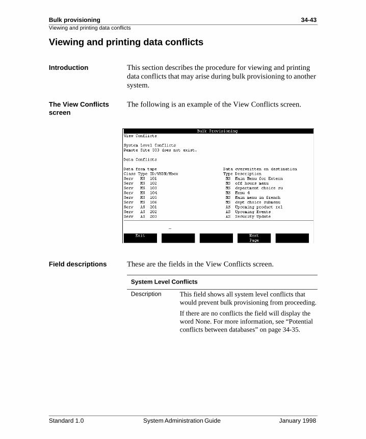
Bulk provisioning 34-43Viewing and printing data conflicts
er
.
Viewing and printing data conflicts
Introduction This section describes the procedure for viewing and printingdata conflicts that may arise during bulk provisioning to anothsystem.
The View Conflicts screen
The following is an example of the View Conflicts screen.
Field descriptions These are the fields in the View Conflicts screen.
System Level Conflicts
Description This field shows all system level conflicts that would prevent bulk provisioning from proceeding
If there are no conflicts the field will display the word None. For more information, see “Potentialconflicts between databases” on page 34-35.
Standard 1.0 System Administration Guide January 1998
34-44 Bulk provisioning Viewing and printing data conflicts
t ,
/
by
Data Conflicts orAll Entries
Description The appropriate field displays when either the Conflicts Only or the All Entries option is chosen.This field is divided into two parts: Data from tapeon the left side, and Data overwritten on destination on the right side of the screen.
Data from tape
Description When the [Conflicts Only] softkey is pressed, thisfield shows only the data in conflict with the targesystem. When the [All Entries] softkey is pressedthis field shows all data that is contained on the provisioning tape for the specified selection criteria.
The information is shown by Class, Type, and IDVSDN/MBox.
a. Class is the general class of data on thetape. Class is Serv, VSDN, or User.
b. Type is the service type represented by the mnemonic used by Voice Service Administration (VSA). This applies to services and VSDNs only.
c. ID/VSDN/MBox is the voice service ID for a service, the DN for VSDNs, and themailbox with a network prefix for users.
Data overwritten on destination
Description This field displays any data on the target systemthat will be overwritten if provisioning proceeds. The data is provided by Type and Description.
• Type applies to services and VSDNs only. It isthe service type of the service as represented the mnemonic used by Voice Service Administration (VSA).
• Description is the target system’s name or the comment field of a data item that will be overwritten.
Note: This field will be blank if the data item doesnot yet exist on the target system.
Standard 1.0 System Administration Guide January 1998
Bulk provisioning 34-45Viewing and printing data conflicts
Viewing data conflicts To view data conflicts before provisioning the data to the newMeridian Mail system, use the following steps.Starting Point: The Provision From Tape screen
Step Action
1 Press the [View Selected] softkey.
Result: The softkeys are replaced by the [Conflicts Only] and [All Entries] softkeys.
2 Use the following table to choose the next step.
Result: The View Conflicts screen displays with the appropriate information provided.
3 Press the [Exit] softkey to return to the Provision From Tape screen.
IF you want to view THEN press softkey
the conflicts between the data on the tape and the data on the target system only
[Conflicts Only].
all entries on the tape (for the specified criteria) and the conflicts on the target system
[All Entries].
Standard 1.0 System Administration Guide January 1998
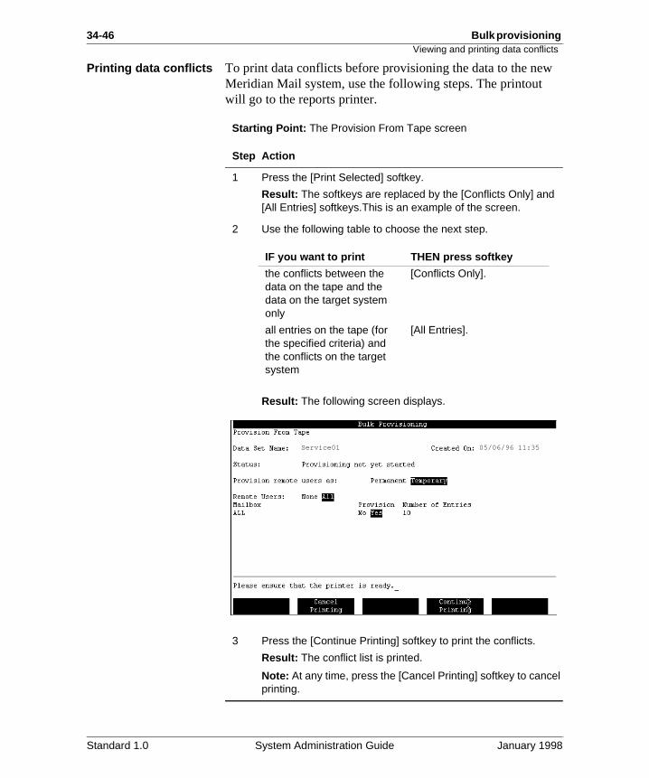
34-46 Bulk provisioning Viewing and printing data conflicts
Printing data conflicts To print data conflicts before provisioning the data to the newMeridian Mail system, use the following steps. The printout will go to the reports printer.Starting Point: The Provision From Tape screen
Step Action
1 Press the [Print Selected] softkey.
Result: The softkeys are replaced by the [Conflicts Only] and [All Entries] softkeys.This is an example of the screen.
2 Use the following table to choose the next step.
Result: The following screen displays.
3 Press the [Continue Printing] softkey to print the conflicts.
Result: The conflict list is printed.
Note: At any time, press the [Cancel Printing] softkey to cancel printing.
IF you want to print THEN press softkey
the conflicts between the data on the tape and the data on the target system only
[Conflicts Only].
all entries on the tape (for the specified criteria) and the conflicts on the target system
[All Entries].
05/06/96 11:35Service01
Standard 1.0 System Administration Guide January 1998
Appendix A
Appendix A
Integrated Mailbox Administration
In this appendix
Overview A-2
Section A: Interaction between IMA and Meridian Mail A-3
Section B: System installation using VMBA A-15
A-2 Integrated Mailbox Administration
ell
s
the
il
Overview
Overview
Introduction Section A: Interaction between IMA and Meridian Mail, describes the Integrated Mailbox Administration feature as was
• the interaction of IMA and Meridian Mail with respect to potential conflicts
• the synchronization of databases
• the implementation and processing differences
In Section B: System installation using VMBA, the proceduredescribe the installation of a system
• at a new site with no preconfigured database on either Meridian 1 core or Meridian Mail
• at a new site with sets and VMBs preconfigured on the Meridian 1 core but nothing configured on Meridian Mail
• at an existing site with VMBs configured on Meridian Mabut no VMBs configured on the Meridian 1 core
Standard 1.0 System Administration Guide January 1998
Integrated Mailbox Administration A-3
Section A: Interaction between IMA and Meridian Mail
In this section
Overview A-4
What is Integrated Mailbox Administration? A-5
IMA data translations A-6
Synchronizing IMA and Meridian Mail databases A-9
IMA and Meridian Mail processing differences and implementation issues
A-10
Standard 1.0 System Administration Guide January 1998
A-4 Integrated Mailbox Administration
d
Overview
Overview
Introduction This section describes Integrated Mailbox Administration andiscusses the interactions between IMA and Meridian Mail.
Standard 1.0 System Administration Guide January 1998
Integrated Mailbox Administration A-5What is Integrated Mailbox Administration?
on d
D
the s.
g
ian om
, h
What is Integrated Mailbox Administration?
Description Integrated Mailbox Administration (IMA) is a feature of Meridian Mail which works in conjunction with the Voice Mailbox Administration (VMBA) feature on the Meridian 1 switch. These features provide a single point for administratiof Meridian 1 (M1) sets, Call Party Name Display (CPND), anMeridian Mail mailboxes.
Benefits IMA/VMBA provides significant time savings for both the installer and the administrator. Set datafile (including CPND)and mailboxes only have to be entered once, in one place (L10 for analog sets or LD 11 for digital sets), saving time and potential for datafill inconsistencies between the two system
This feature allows the installer or the administrator to add auser and a mailbox from the Meridian 1 terminal by specifyinwhether the user requires voice mail capabilities. If the user requires a mailbox, the Meridian 1 core sends a message toMeridian Mail to request that the user be added to the MeridMail database. This eliminates the step of adding the user frMeridian Mail.
Prerequisite In order to use the Integrated Mailbox Administration featureyour Meridian 1 must be running X11 Release 19 or later witthe Voice Mailbox Administration feature installed. (VMBA requires X11 Release 19.2x or later.)
Standard 1.0 System Administration Guide January 1998
A-6 Integrated Mailbox Administration
re
. re or
f
IMA data translations
IMA data translations
Introduction The Meridian 1 databases contain a subset of the data that arequired to completely configure a voice mail user. When a message is sent by the Meridian 1 to Meridian Mail to add auser, Meridian Mail will use the information with some predefined defaults and rules to add the user to the MeridianMail database.
Example By definition, the Primary DN is the same as the mailbox number and the same as the Message Waiting Indication DNThe IMA data translations table below shows the data that asent by the Meridian 1 and the data that are actually stored feach voice mail user.
Before you begin Before adding users from the Meridian 1 using VMBA, the following steps must be carried out in Meridian Mail.
1. Define classes of service for the system.
For more information, see Chapter 26, “Class of Service administration”.
2. For added mailbox security, you can define a passwordprefix.
For more information, see “Password prefix” on page 6-136.
ATTENTION
If VMBA is enabled, do not modify those parameters which are common to both systems in Meridian Mail as this can lead to inconsistencies. The VMBA feature is considered the master and will override these settings. Inecessary, you can customize those parameters which appear only in Meridian Mail since there is no chance ofconflict.
Standard 1.0 System Administration Guide January 1998
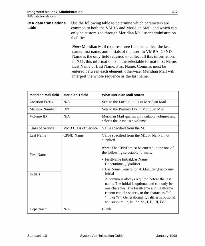
Integrated Mailbox Administration A-7IMA data translations
n n
e,
ll
IMA data translations table
Use the following table to determine which parameters are common to both the VMBA and Meridian Mail, and which caonly be customized through Meridian Mail user administratiofacilities.
Note: Meridian Mail requires three fields to collect the last name, first name, and initials of the user. In VMBA, CPND Name is the only field required to collect all this information.In X11, this information is in the selectable format First NamLast Name or Last Name, First Name. Commas must be entered between each element; otherwise, Meridian Mail wiinterpret the whole sequence as the last name.
Meridian Mail field Meridian 1 field What Meridian Mail stores
Location Prefix N/A Sets to the Local Site ID in Meridian Mail
Mailbox Number DN Sets to the Primary DN in Meridian Mail
Volume ID N/A Meridian Mail queries all available volumes andselects the least used volume
Class of Service VMB Class of Service Value specified from the M1
Last Name CPND Name Value specified from the M1, or blank if not supplied
Note: The CPND must be entered in the one of the following selectable formats:
• FirstName Initial,LastName Generational_Qualifier
• LastName Generational_Qualifier,FirstName Initial
A comma is always required before the last name. The initial is optional and can only be one character. The FirstName and LastName cannot contain spaces, or the characters “+”, “_”, or “?”. Generational_Qualifier is optional, and supports Jr, Jr., Sr, Sr., I, II, III, IV.
First Name
Initials
Department N/A Blank
Standard 1.0 System Administration Guide January 1998
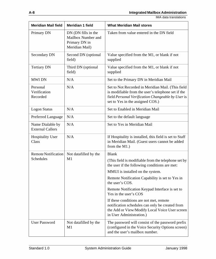
A-8 Integrated Mailbox Administration
y
x )
IMA data translations
Primary DN DN (DN fills in the Mailbox Number and Primary DN in Meridian Mail)
Taken from value entered in the DN field
Secondary DN Second DN (optional field)
Value specified from the M1, or blank if not supplied
Tertiary DN Third DN (optional field)
Value specified from the M1, or blank if not supplied
MWI DN N/A Set to the Primary DN in Meridian Mail
Personal Verification Recorded
N/A Set to Not Recorded in Meridian Mail. (This fieldis modifiable from the user’s telephone set if thefield Personal Verification Changeable by User is set to Yes in the assigned COS.)
Logon Status N/A Set to Enabled in Meridian Mail
Preferred Language N/A Set to the default language
Name Dialable by External Callers
N/A Set to Yes in Meridian Mail
Hospitality User Class
N/A If Hospitality is installed, this field is set to Staff in Meridian Mail. (Guest users cannot be addedfrom the M1.)
Remote Notification Schedules
Not datafilled by the M1
Blank
(This field is modifiable from the telephone set bthe user if the following conditions are met:
MMUI is installed on the system.
Remote Notification Capability is set to Yes in the user’s COS.
Remote Notification Keypad Interface is set to Yes in the user’s COS
If these conditions are not met, remote notification schedules can only be created from the Add or View/Modify Local Voice User screenin User Administration.)
User Password Not datafilled by the M1
The password will consist of the password prefi(configured in the Voice Security Options screenand the user’s mailbox number.
Meridian Mail field Meridian 1 field What Meridian Mail stores
Standard 1.0 System Administration Guide January 1998
Integrated Mailbox Administration A-9Synchronizing IMA and Meridian Mail databases
s
e
of e 1
n
Synchronizing IMA and Meridian Mail databases
Introduction The Meridian 1 and Meridian Mail databases are stored on separate systems; however, they can diverge under the following conditions:
• core elements of mailboxes are changed with Meridian Mail user administration
• the X11 VMBA database is loaded while VMBA is disabled
• the X11 VMBA database is updated while the AML link idown or Meridian Mail is out of service
The databases must be synchronized in one of two ways: through automatic or manually invoked audits or through uploading Meridian Mail data to the X11 VMBA database.
Audit synchronization The two databases are synchronized through the use of automatic or manually invoked audits. If a variance is found during an audit, the result depends on whether DATA_CORRECT is enabled or disabled (X11 LD 17). If enabled, the audit will automatically change the data in Meridian Mail to conform to the X11 VMBA database. If disabled, the audit will flag variances to the Meridian 1 administration printer, allowing the administrator to determinthe appropriate corrective action.
Uploading data from Meridian Mail’s database to IMA
Another way of synchronizing the two databases is to uploadMeridian Mail data to the X11 VMBA database.
Sites upgrading to X11 Release 19 often already have a Meridian Mail system configured. To eliminate manual entry all the VMBA fields, an upload of existing mailbox data into thVMBA data fields is available. The upload is initiated from X1LD 48.
See X11 documentation for more details
More detailed information, including overlays, are provided ithe X11 Features and Services document (NTP 555-3001-305) in the chapter, “Meridian Mail Voice Mailbox Administration.”
Standard 1.0 System Administration Guide January 1998
A-10 Integrated Mailbox Administration
e eed
:
y
y r,
as
the
e
IMA and Meridian Mail processing differences and implementation issues
IMA and Meridian Mail processing differences and implementation issues
Introduction This section describes a number of feature interactions, namprocessing differences, and implementation issues that you nto be aware of.
Meridian Mail features interactions
Make note of the following Meridian Mail feature interactions
• This feature does not support guest users in a Hospitalitenvironment.
This feature expects that the Meridian 1 User’s Primary DN is the user’s mailbox number. Staff users will typicallhave the primary DN equal the mailbox number. Howeveguest users will not have a room’s primary DN the sametheir mailbox number.
• If the Network Message Service (NMS) is installed, onlyusers at the local site can be added via the Meridian 1.
The Location Prefix field defaults to the Local Site ID. Users at satellite locations must be added manually via Meridian Mail terminal. All NMS administration should bedone at the Meridian Mail administration terminal.
• IMA does not support the Meridian Mail Multi-customer feature.
• Configured mailboxes will use the default language of thdefault customer group on Meridian Mail.
If the default language is English, all remotely configuredmailboxes will be assigned the English language option.Multi-language interaction between the Meridian 1 and Meridian Mail is not supported.
• The IMA feature supports only Local Voice Users.
• IMA should not be run while the Meridian Mail AutoAdmin feature is active.
Standard 1.0 System Administration Guide January 1998
Integrated Mailbox Administration A-11IMA and Meridian Mail processing differences and implementation issues
il
ers
er
, on y
by
nd
e
X11 Meridian Mail database differences
You should be aware of the following X11 Meridian Mail database differences:
• Database audits run every five days.
If mailbox changes are made directly at the Meridian Maadministration terminal, they may not be detected and corrected for up to five days.
• The combined first and last name is limited to 27 characton the Meridian 1.
Meridian Mail supports up to 21 characters for the first name and 41 characters for the last name. This feature overrides these limits to total 27 characters.
• Meridian Mail limits first names to 21 characters.
If a first name is configured on the Meridian 1 (M1) coreand is greater than 21 characters, it will be truncated byMeridian Mail.
• Meridian Mail only supports a subset of the characters supported for names on the Meridian 1 core.
Meridian Mail does not support the international charactset option of X11 (option 211). Meridian Mail only supports North American ASCII characters (excluding +_, and?) in the name fields. If a name that is configured the Meridian 1 core contains characters not supported bMeridian Mail, Meridian Mail will reject the name.
• Multiple languages on the Meridian 1 are not supported the IMA feature.
• When entering the CPND name in X11, the first name alast name (the order of names is selectable) must be separated by commas.
If commas are not entered, Meridian Mail will interpret thentire sequence of letters as the last name.
• If a mailbox is deleted on the Meridian 1 but not successfully deleted in Meridian Mail, an “orphaned” mailbox will result.
These mailboxes will be recovered if the same DN is reused in the Meridian 1 (in other words, Meridian Mail will delete the old one and add the new one), but will remain in Meridian Mail if they are not.
Standard 1.0 System Administration Guide January 1998
A-12 Integrated Mailbox Administration
by
x
e,
il
n
in
IMA and Meridian Mail processing differences and implementation issues
X11 VMBA and Meridian Mail IMA interactions
You should be aware of the following X11 VMBA and Meridian Mail interactions:
• Depending on how the VMBA option is set, if a mailbox already exists on Meridian Mail and VMBA requests a mailbox to be created for the DN corresponding to that mailbox, IMA will do one of two things:
- delete the existing mailbox (including its voice messages) and replace it with the mailbox requestedVMBA
- keep the mailbox messages but configure the mailboaccording to the VMBA data elements
• VMBA is the master database.
Changes made using VMB will always be copied to Meridian Mail.
• If a DN must be changed on a set on the Meridian 1 corthe mailbox will have to be deleted and added again in Meridian Mail prior to changing the DN on theMeridian 1 core.
• The X11 administrator must set VMBA to off for DNs onthe Meridian 1 which should not have mailboxes.
• When making changes to data elements using VMBA, make sure the same mailbox is not open in Meridian Mauser administration.
If this happens, the download will stay in pending state until the problem is resolved.
X11 VMB limitations You should be aware of the following X11 VMB interactions:
• Only one Meridian Mail system is supported per Meridia1 system.
• Only one customer can be configured on the Meridian 1 core for this application.
• Only 500, 2500, SL1, and digital set types are supportedthis release.
• The mailbox status that is shown in Overlay 20 in the Meridian 1 indicates the status of the mailbox on the Meridian 1 core and not the status of the mailbox on Meridian Mail.
Standard 1.0 System Administration Guide January 1998
Integrated Mailbox Administration A-13IMA and Meridian Mail processing differences and implementation issues
a in
is
ote
For example, if a mailbox is disabled on Meridian Mail asresult of a security violation, the state will not be updatedthe Meridian 1 core.
• Operator revert is not supported because the revert DN user-changeable.
• Configuration of Meridian Mail customer numbers, department numbers and mailbox passwords from the Meridian 1 core are not supported in this release.
• Mailboxes cannot be configured for sets served by a remMeridian Mail subsystem.
Standard 1.0 System Administration Guide January 1998
A-14 Integrated Mailbox Administration
IMA and Meridian Mail processing differences and implementation issuesStandard 1.0 System Administration Guide January 1998
Integrated Mailbox Administration A-15
Section B: System installation using VMBA
In this section
Overview A-16
Installing at a new site without a preconfigured database on Meridian Mail or the Meridian 1 core
A-17
Installing at a new site with sets and VMBs preconfigured on the Meridian 1 core but not on Meridian Mail
A-18
Installing at an existing site with VMBs preconfigured on Meridian Mail but not the Meridian 1 core
A-20
Standard 1.0 System Administration Guide January 1998
A-16 Integrated Mailbox Administration
on
ed n
Overview
Overview
introduction This section describes the three possible system installationscenarios when using VMBA:
• installation at a new site with no preconfigured databaseeither the Meridian 1 core or Meridian Mail
• installation at a new site with sets and VMBs preconfiguron the Meridian 1 core but nothing configured on MeridiaMail
• installation at an existing site with VMBs configured on Meridian Mail but no VMBs configured on the Meridian 1 core
Standard 1.0 System Administration Guide January 1998
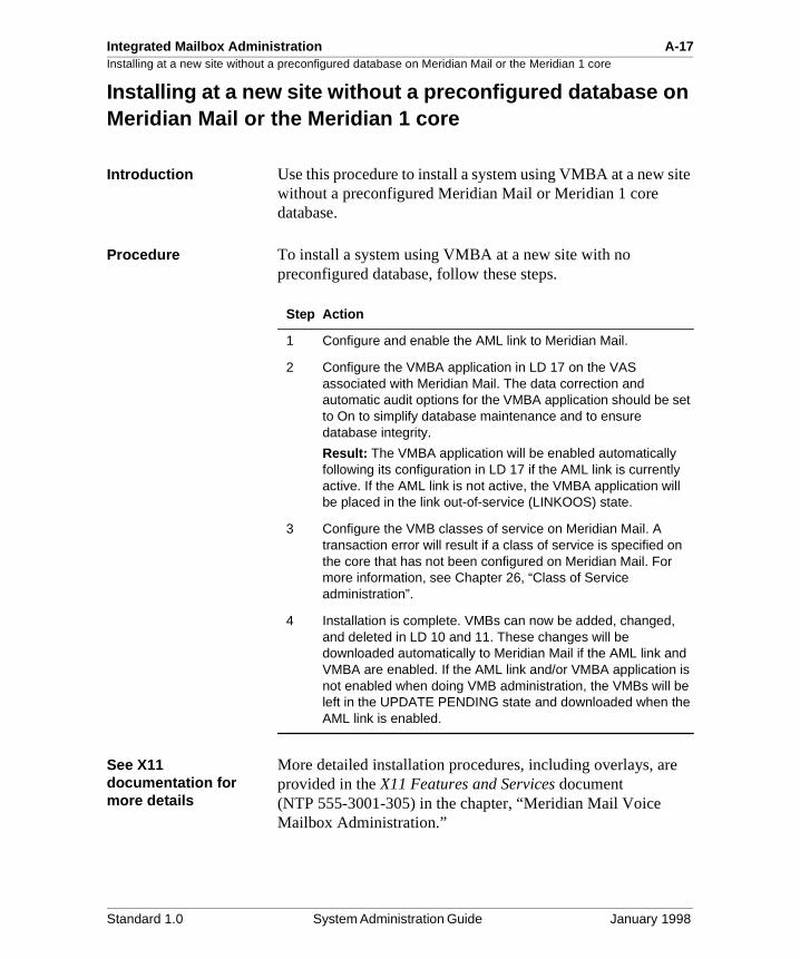
Integrated Mailbox Administration A-17Installing at a new site without a preconfigured database on Meridian Mail or the Meridian 1 core
ite
Installing at a new site without a preconfigured database on Meridian Mail or the Meridian 1 core
Introduction Use this procedure to install a system using VMBA at a new swithout a preconfigured Meridian Mail or Meridian 1 core database.
Procedure To install a system using VMBA at a new site with no preconfigured database, follow these steps.
See X11 documentation for more details
More detailed installation procedures, including overlays, areprovided in the X11 Features and Services document (NTP 555-3001-305) in the chapter, “Meridian Mail Voice Mailbox Administration.”
Step Action
1 Configure and enable the AML link to Meridian Mail.
2 Configure the VMBA application in LD 17 on the VAS associated with Meridian Mail. The data correction and automatic audit options for the VMBA application should be set to On to simplify database maintenance and to ensure database integrity.
Result: The VMBA application will be enabled automatically following its configuration in LD 17 if the AML link is currently active. If the AML link is not active, the VMBA application will be placed in the link out-of-service (LINKOOS) state.
3 Configure the VMB classes of service on Meridian Mail. A transaction error will result if a class of service is specified on the core that has not been configured on Meridian Mail. For more information, see Chapter 26, “Class of Service administration”.
4 Installation is complete. VMBs can now be added, changed, and deleted in LD 10 and 11. These changes will be downloaded automatically to Meridian Mail if the AML link and VMBA are enabled. If the AML link and/or VMBA application is not enabled when doing VMB administration, the VMBs will be left in the UPDATE PENDING state and downloaded when the AML link is enabled.
Standard 1.0 System Administration Guide January 1998
A-18 Integrated Mailbox Administration
ed
Installing at a new site with sets and VMBs preconfigured on the Meridian 1 core but not on Meridian Mail
Installing at a new site with sets and VMBs preconfigured on the Meridian 1 core but not on Meridian Mail
Introduction Use the following procedures to install a system using VMBAwhere the VMB database is preconfigured on the Meridian 1core prior to the installation at the customer site (no VMBs should be configured on Meridian Mail). The process is dividinto two parts:
• preconfiguring the database
• installing the database at the customer site
Preconfiguring the database
To preconfigure the database, follow these steps.
Step Action
1 Configure the VMBA application in LD 17 on the VAS associated with Meridian Mail. The data correction and automatic audit options for the VMBA application should be set to On to simplify database maintenance and to ensure database integrity. The AML link does not have to be configured at this point since there is no actual hardware to enable.
2 Configure the sets and associated VMBs. The VMBs will be left in the UPDATE PENDING state.
Standard 1.0 System Administration Guide January 1998
Integrated Mailbox Administration A-19Installing at a new site with sets and VMBs preconfigured on the Meridian 1 core but not on Meridian Mail
ps.
Installing the database at the customer site
To install the database at the customer site, follow these ste
See X11 documentation for more details
More detailed installation procedures, including overlays, areprovided in the X11 Features and Services document (NTP 555-3001-305) in the chapter, “Meridian Mail Voice Mailbox Administration.”
Step Action
1 Ensure that the Meridian Mail database has been configured with the VMB classes of service that were used when preconfiguring the core database. For more information, see Chapter 26, “Class of Service administration”.
.
2 Configure and enable the AML link to Meridian Mail.
3 The VMBA application should be enabled automatically unless it is in the manually disabled state. If it is disabled, then the VMBA application will have to be enabled in LD 48 using the ENL VMBA <vsid> command.
When the VMBA application has been successfully enabled, the preconfigured mailbox data will begin downloading to Meridian Mail. The VMBs successfully downloaded and configured can be printed using the PRT VMB option in LD 20.
4 When the download has completed, reported errors should be manually corrected.
5 Initiate the database audit by entering ENL VMBA <vsid> AUDT ALL in LD 48. This will verify that the VMB and CPND data on the core matches the data on Meridian Mail. The status of the audit can be obtained by entering STAT VMBA <vsid> or STAT VMBA <vsid> AUDT in LD 48.
Result: Errors detected by the audit will be corrected automatically. The installation is complete.
ATTENTION
Do not proceed any further until this has been completed.
Standard 1.0 System Administration Guide January 1998
A-20 Integrated Mailbox Administration
sed n
ail n be ose
mes
d
Installing at an existing site with VMBs preconfigured on Meridian Mail but not the Meridian 1 core
Installing at an existing site with VMBs preconfigured on Meridian Mail but not the Meridian 1 core
Introduction Use this procedure for installing a system using VMBA at anexisting site. In most cases, these sites will have the VMBs configured already. The upload command in LD 48 can be uto upload the existing Meridian Mail VMB data to the Meridia1 core.
Cleanup may be necessary
This command causes name data configured on Meridian Mto be uploaded; existing names on the core will be overwrittewith the names on Meridian Mail. Some name cleanup may necessary if these names on the core are not the same as thon Meridian Mail. Once this cleanup is complete, name administration becomes easier; it is necessary to change naon the Meridian 1 core only (instead of on the core and on Meridian Mail).
Procedure To install the system at an existing site with VMBs configureon Meridian Mail but not on the Meridian 1 core, follow thesesteps.
Step Action
1 Configure and enable the AML link to Meridian Mail.
2 Configure the VMBA application in LD 17 on the VAS associated with Meridian Mail. The data correction and automatic audit options for the VMBA application should be set to Off until this installation has been completed.
3 The application will be enabled automatically following the configuration of the VMBA application in LD 17 if the AML link is currently active. If the AML link is not active, the VMBA application will be placed in the link out-of-service (LINKOOS) state.
4 Initiate the database upload by entering ENL VMBA <vsid> UPLD ALL in LD 48.
5 Periodically check the status of the upload by entering the command STAT VMBA <vsid> or STAT VMBA <vsid> UPLD AUDT in LD 48.
Standard 1.0 System Administration Guide January 1998
Integrated Mailbox Administration A-21Installing at an existing site with VMBs preconfigured on Meridian Mail but not the Meridian 1 core
See X11 documentation for more detailsMore detailed installation procedures, including overlays, areprovided in the X11 Features and Services document (NTP 555-3001-305) in the chapter, “Meridian Mail Voice Mailbox Administration.”
6 When an UPLOAD COMPLETE message is printed, manually resolve any errors that may have occurred during the upload.
Result: The upload is complete.
7 Initiate the database audit by entering ENL VMBA <vsid> AUDT ALL in LD 48. This will verify that the VMB and CPND data on the core matches the data on Meridian Mail.
8 Manually resolve any errors that may have been uncovered by the audit.
Result: The audit is complete. The Meridian 1 core and the Meridian Mail databases are synchronized. Perform any cleanup on names, if necessary.
9 Configure the data correction and automatic audit options as desired. These options are recommended to maintain database integrity.
Result: The installation is complete. Ongoing administration of the VMBs can be performed on the Meridian 1 core from now on.
Step Action
Standard 1.0 System Administration Guide January 1998
A-22 Integrated Mailbox Administration
Installing at an existing site with VMBs preconfigured on Meridian Mail but not the Meridian 1 coreStandard 1.0 System Administration Guide January 1998
Appendix B
Meridian Mail AutoAdmin Utilit y
In this cha pter
Overview B-2
Introduction B-3
Meridian Mail AutoAdmin installation B-5
AutoAdmin Configurator B-12
AutoAdmin Utility B-21
The AutoAdmin window B-25
Using Meridian Mail AutoAdmin B-34
Troubleshooting B-51
B-2 Meridian Mail AutoAdmin Utility
OverviewOverview
Introduction This chapter explains how to install, configure, and use the Meridian Mail AutoAdmin Utility.
Standard 1.0 System Administration Guide January 1998
Meridian Mail AutoAdmin Utility B-3Introduction
to
to
tor
ate
y
s 95
the m ort .6
Introduction
What is the Meridian Mail AutoAdmin Utilit y?
The Meridian Mail AutoAdmin Utility provides a means of propagating user database information from a central systemother local or off-site Meridian Mail systems.
Who should use AutoAdmin?
Large messaging customers of Meridian Mail who often needadminister and manage multiple systems within their organization will benefit from using AutoAdmin. These systems can support thousands of users, and an administramay have a limited amount of time to get the additions and changes done.
AutoAdmin provides an easy way for customers to get the required information from the local user database and propagit to any of their other Meridian Mail systems.
Supported platforms AutoAdmin works on all Meridian Mail platforms supported bMM12, except the Compact Option.
On the windows side, the Meridian Mail AutoAdmin Utility habeen developed to use a PC and runs on Microsoft Windowsand Windows NT 4.0.
Connectin g Meridian Mail and the PC
The connection between Meridian Mail and the PC is called MSLink (Message server link) and each Meridian Mail systecan have only one of these links. The maximum supported prate on this link is 38.4 Kbytes for the MMP40 systems and 9Kbytes for the MSM and Mod GP systems, subject to the cumulative port rate on each node for these systems.
Standard 1.0 System Administration Guide January 1998
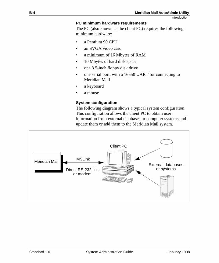
B-4 Meridian Mail AutoAdmin Utility
d
Introduction
PC minimum hardware re quirementsThe PC (also known as the client PC) requires the following minimum hardware:
• a Pentium 90 CPU
• an SVGA video card
• a minimum of 16 Mbytes of RAM
• 10 Mbytes of hard disk space
• one 3.5-inch floppy disk drive
• one serial port, with a 16550 UART for connecting to Meridian Mail
• a keyboard
• a mouse
System configurationThe following diagram shows a typical system configuration.This configuration allows the client PC to obtain user information from external databases or computer systems anupdate them or add them to the Meridian Mail system.
Meridian MailMSLink
Direct RS-232 linkor modem
Client PC
External databasesor systems
Standard 1.0 System Administration Guide January 1998
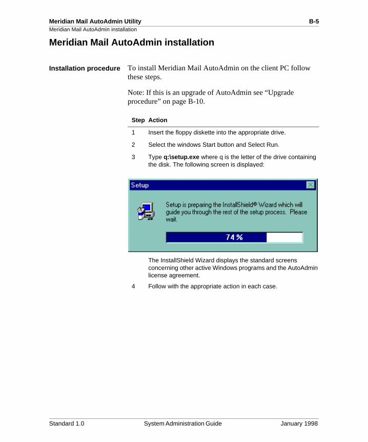
Meridian Mail AutoAdmin Utility B-5Meridian Mail AutoAdmin installation
Meridian Mail AutoAdmin installation
Installation procedure To install Meridian Mail AutoAdmin on the client PC follow these steps.
Note: If this is an upgrade of AutoAdmin see “Upgrade procedure” on page B-10.
Step Action
1 Insert the floppy diskette into the appropriate drive.
2 Select the windows Start button and Select Run.
3 Type q:\setup.exe where q is the letter of the drive containing the disk. The following screen is displayed:
The InstallShield Wizard displays the standard screens concerning other active Windows programs and the AutoAdmin license agreement.
4 Follow with the appropriate action in each case.
Standard 1.0 System Administration Guide January 1998
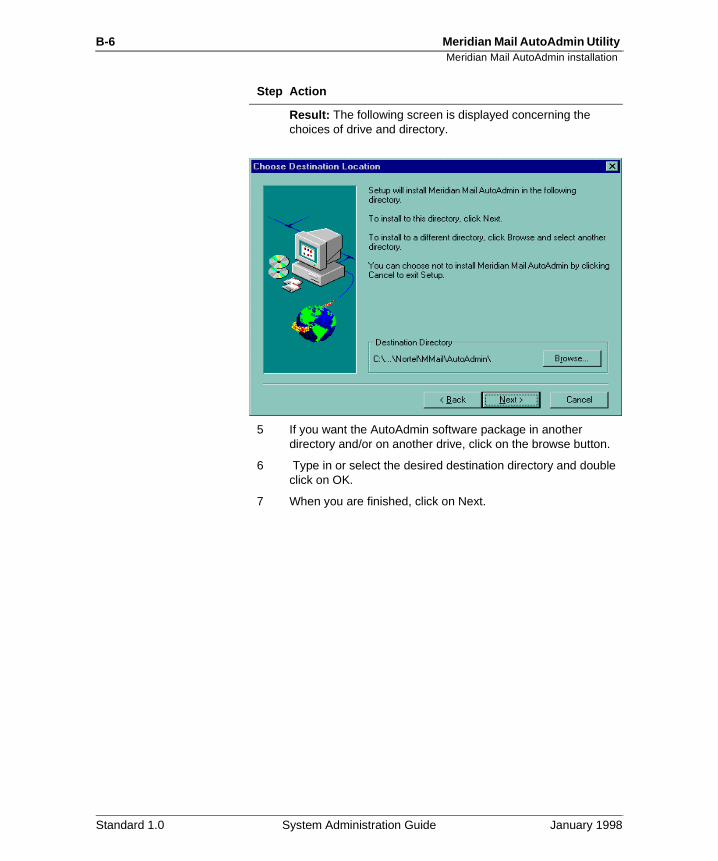
B-6 Meridian Mail AutoAdmin Utility Meridian Mail AutoAdmin installation
Result: The following screen is displayed concerning the choices of drive and directory.
5 If you want the AutoAdmin software package in another directory and/or on another drive, click on the browse button.
6 Type in or select the desired destination directory and double click on OK.
7 When you are finished, click on Next.
Step Action
Standard 1.0 System Administration Guide January 1998
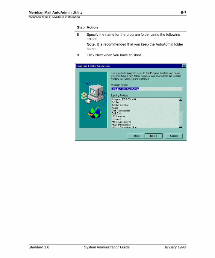
Meridian Mail AutoAdmin Utility B-7Meridian Mail AutoAdmin installation
8 Specify the name for the program folder using the following screen.
Note: It is recommended that you keep the AutoAdmin folder name.
9 Click Next when you have finished.
Step Action
Standard 1.0 System Administration Guide January 1998
B-8 Meridian Mail AutoAdmin Utility Meridian Mail AutoAdmin installation
Result: The following screen is displayed to verify the information you have input.
10 If you wish to change anything you have entered so far, click Back.
Otherwise, click Next to continue with the installation.
Step Action
Standard 1.0 System Administration Guide January 1998
Meridian Mail AutoAdmin Utility B-9Meridian Mail AutoAdmin installation
11 Click Finish to complete the installation of AutoAdmin.
Result: Once you finish the installation, your system is configured for one local site with default settings.
If you require more configuration, or need to modify the existing local site, use the configurator program that follows immediately from the installation.
Note: You may deselect the View ReadMe file. However, it is recommended that users read the ReadMe file for information on copyright, version, and support.
Step Action
Standard 1.0 System Administration Guide January 1998
B-10 Meridian Mail AutoAdmin Utility Meridian Mail AutoAdmin installation
Upgrade procedure To upgrade to AutoAdmin, follow these steps.
Note: If you try to upgrade using an older version of AutoAdmin, the procedure will abort.
Step Action
1 Insert the floppy diskette with the AutoAdmin upgrade into the appropriate drive.
2 Select the Windows Start button, and select Run.
3 Type q:\setup.exe where q is the letter of the drive containing the disk.
Result: The following screen is displayed.
The InstallShield Wizard displays the standard screens concerning other active Windows programs.
4 Follow with the appropriate action in each case.
Standard 1.0 System Administration Guide January 1998
Meridian Mail AutoAdmin Utility B-11Meridian Mail AutoAdmin installation
Standard 1.0 System Administration Guide February 1998
Result: Once this is done, the following screen is displayed.
5 If you wish to upgrade, select Next and go to step 6, or select Cancel to end the procedure without an upgrade.
6 Click Next.
Result: The upgrade is installed in the same directory as the previous version of AutoAdmin.
Result: When the upgrade is completed, the following message screen is displayed:
7 Click OK to finish the upgrade.
Step Action
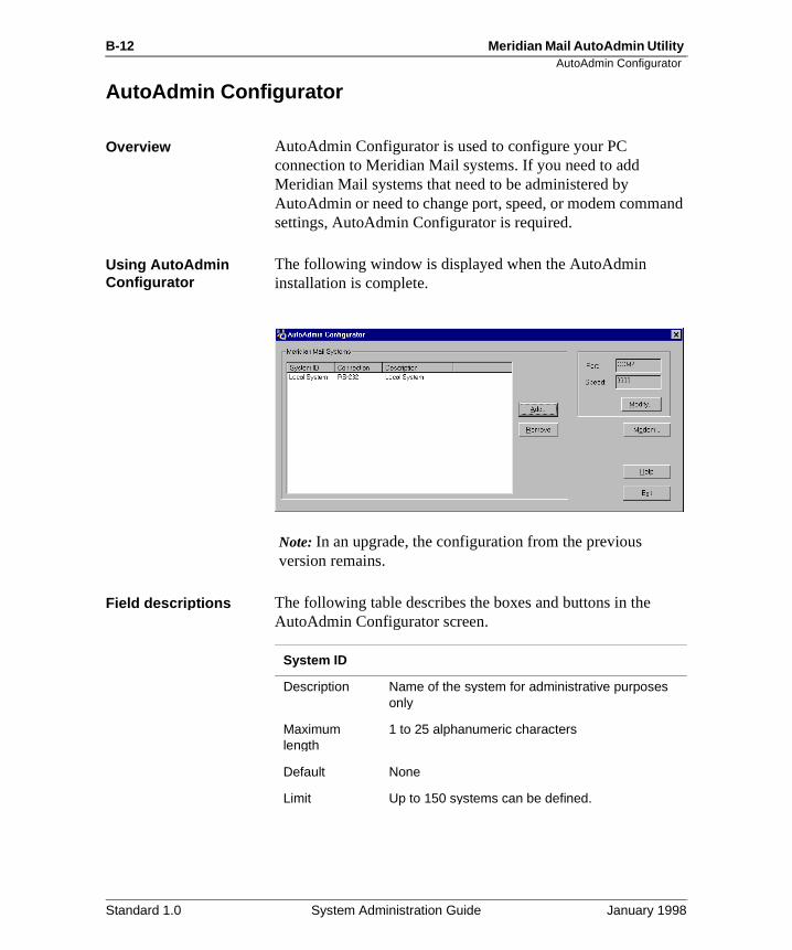
B-12 Meridian Mail AutoAdmin Utility AutoAdmin Configurator
nd
AutoAdmin Confi gurator
Overview AutoAdmin Configurator is used to configure your PC connection to Meridian Mail systems. If you need to add Meridian Mail systems that need to be administered by AutoAdmin or need to change port, speed, or modem commasettings, AutoAdmin Configurator is required.
Usin g AutoAdmin Confi gurator
The following window is displayed when the AutoAdmin installation is complete.
Note: In an upgrade, the configuration from the previous version remains.
Field descri ptions The following table describes the boxes and buttons in the AutoAdmin Configurator screen.
System ID
Description Name of the system for administrative purposes only
Maximumlength
1 to 25 alphanumeric characters
Default None
Limit Up to 150 systems can be defined.
Standard 1.0 System Administration Guide January 1998
Meridian Mail AutoAdmin Utility B-13AutoAdmin Configurator
Connection
Description The type of connection, which may be a serial (RS-232) connection or the dialing number of a modem
Values RS-232, dialing number
Description
Description Optional field to describe Meridian Mail system
Maximumlength
0 to 50 alphanumeric characters
Default None
Add
Description Select this button when you want to add a Meridian Mail site. Type the site information in the System Settings dialog box that is displayed.
Remove
Description Select this button when you wish to remove a Meridian Mail site from your site ID list. You must click on the site ID you wish to remove before clicking the Remove button.
Port
Description Displays the active serial port on the PC that links AutoAdmin to a Meridian Mail system or to a modem. Although these ports are supported, your PC may or may not have them.
This field is read-only. To modify the setting, select the Modify button, and change the setting in the dialog box it presents.
Default COM 1
Range COM 1, COM 2, COM 3, COM 4
Standard 1.0 System Administration Guide January 1998
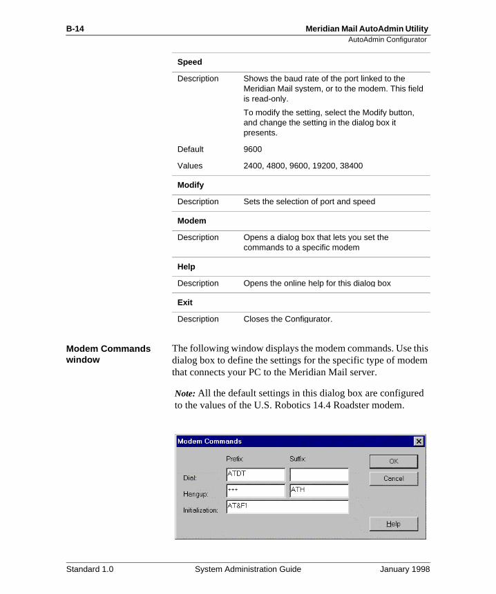
B-14 Meridian Mail AutoAdmin Utility AutoAdmin Configurator
is m
Modem Commands window
The following window displays the modem commands. Use thdialog box to define the settings for the specific type of modethat connects your PC to the Meridian Mail server.
Note: All the default settings in this dialog box are configuredto the values of the U.S. Robotics 14.4 Roadster modem.
Speed
Description Shows the baud rate of the port linked to the Meridian Mail system, or to the modem. This field is read-only.
To modify the setting, select the Modify button, and change the setting in the dialog box it presents.
Default 9600
Values 2400, 4800, 9600, 19200, 38400
Modify
Description Sets the selection of port and speed
Modem
Description Opens a dialog box that lets you set the commands to a specific modem
Help
Description Opens the online help for this dialog box
Exit
Description Closes the Configurator.
Standard 1.0 System Administration Guide January 1998
Meridian Mail AutoAdmin Utility B-15AutoAdmin Configurator
Field descri ptions The following table describes the boxes and buttons of the Modem Commands window.
Dial Prefix
Description Shows the prefix string for dialing the modem’s phone number.
Default ATDT
Hangup Prefix
Description Shows the prefix string for terminating the call.
Default +++
Dial Suffix
Description Shows the suffix string for dialing the modem’s phone number.
Default Blank
Hangup Suffix
Description Shows the suffix string for terminating the call.
Default ATH
Initialization
Description Shows the modem initialization string that identifies the specific modem for the PC.
Maximumlength
50 alphanumeric characters
Default AT&F1
OK
Description Closes the dialog box and saves the changes.
Cancel
Description Closes the dialog box without saving the changes.
Help
Description Opens the online help for this dialog box.
Standard 1.0 System Administration Guide January 1998
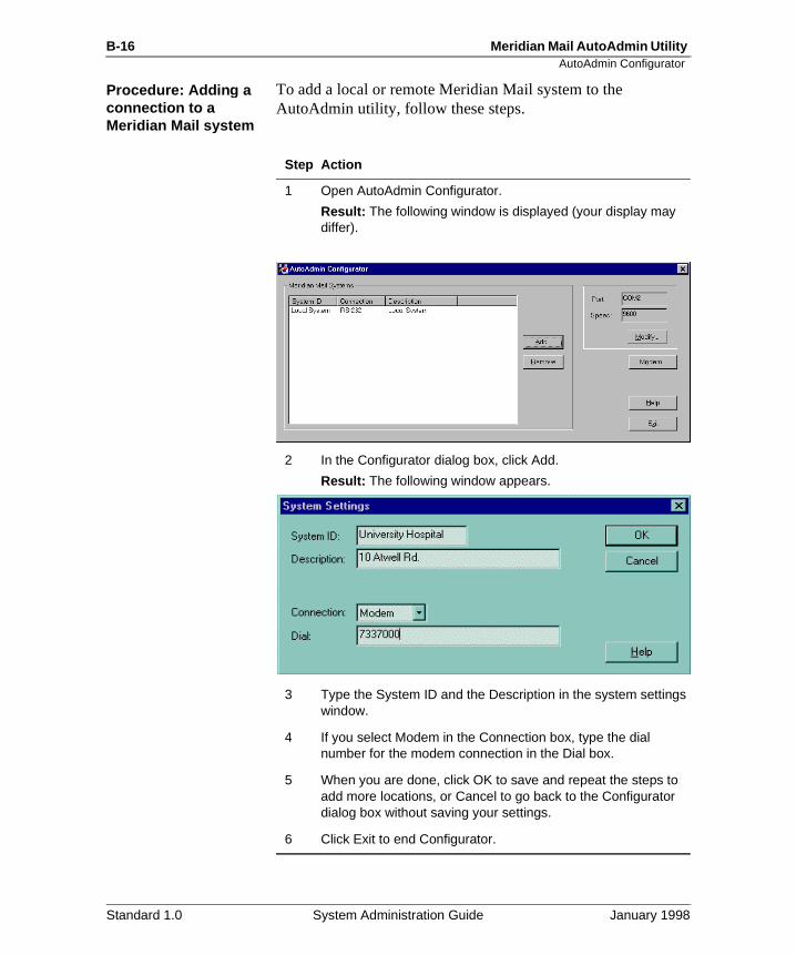
B-16 Meridian Mail AutoAdmin Utility AutoAdmin Configurator
Procedure: Addin g a connection to a Meridian Mail s ystem
To add a local or remote Meridian Mail system to the AutoAdmin utility, follow these steps.
Step Action
1 Open AutoAdmin Configurator.
Result: The following window is displayed (your display may differ).
2 In the Configurator dialog box, click Add.
Result: The following window appears.
3 Type the System ID and the Description in the system settings window.
4 If you select Modem in the Connection box, type the dial number for the modem connection in the Dial box.
5 When you are done, click OK to save and repeat the steps to add more locations, or Cancel to go back to the Configurator dialog box without saving your settings.
6 Click Exit to end Configurator.
Standard 1.0 System Administration Guide January 1998
Meridian Mail AutoAdmin Utility B-17AutoAdmin Configurator
Procedure: Chan ging settin gs in Confi gurator
To change your PC to Meridian Mail (or modem) communication settings, follow these steps.
Step Action
1 Open AutoAdmin Configurator.
Result: The following window is displayed (your display may differ).
2 In the Configurator dialog box, click Modify, or double-click the System ID you wish to modify.
Result: The Communications Settings dialog box appears.
3 Select the port setting from the Port list.
Result: The following screen is displayed:
4 To select the baud rate of the connection, select from the Speed list.
5 Click OK to save the settings and return to the Configurator dialog box , or cancel to bring up the Configurator dialog box without saving your newly entered settings.
Standard 1.0 System Administration Guide January 1998
B-18 Meridian Mail AutoAdmin Utility AutoAdmin Configurator
t ual.
Procedure: Chan ging the modem settin gs
To change your modem settings, follow these steps.
Note: Change the settings for the modem connection if you have changed the modem or if you are not using the defaulU.S. Robotics modem. Refer to the modem's technical man
Step Action
1 Open AutoAdmin Configurator.
Result: The following window is displayed (your display may differ).
2 In the Configurator dialog box, click Modem.
Result: The following screen is displayed (your screen may differ).
3 In the Modem Commands dialog box, enter the Dial Prefix.
4 To define the suffix string to dial the modem, enter the Dial Suffix.
5 Repeat steps 3 and 4 for the Hangup Prefix and Suffix.
Standard 1.0 System Administration Guide January 1998
Meridian Mail AutoAdmin Utility B-19AutoAdmin Configurator
6 To define the initialization string that identifies the particular modem you are using, enter the initialization string.
7 When you have completed your entries, click OK to save the settings or click cancel if you don’t want to save.
Result: In either case, you are returned to the Configurator dialog box.
8 Click Exit to end configurator.
Step Action
Standard 1.0 System Administration Guide January 1998
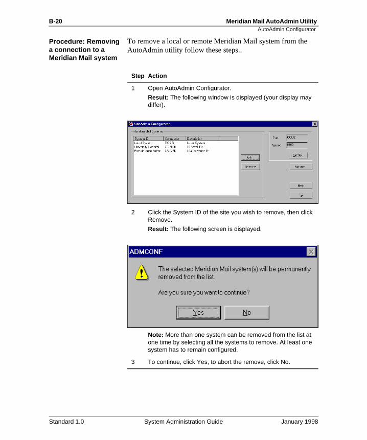
B-20 Meridian Mail AutoAdmin Utility AutoAdmin Configurator
Procedure: Removin g a connection to a Meridian Mail s ystem
To remove a local or remote Meridian Mail system from the AutoAdmin utility follow these steps..
Step Action
1 Open AutoAdmin Configurator.
Result: The following window is displayed (your display may differ).
2 Click the System ID of the site you wish to remove, then click Remove.
Result: The following screen is displayed.
Note: More than one system can be removed from the list at one time by selecting all the systems to remove. At least one system has to remain configured.
3 To continue, click Yes, to abort the remove, click No.
Standard 1.0 System Administration Guide January 1998
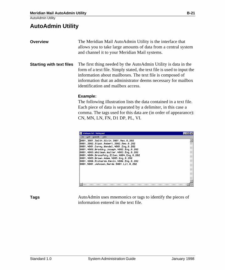
Meridian Mail AutoAdmin Utility B-21AutoAdmin Utility
m
e
ox
. ce):
AutoAdmin Utilit y
Overview The Meridian Mail AutoAdmin Utility is the interface that allows you to take large amounts of data from a central systeand channel it to your Meridian Mail systems.
Startin g with text files The first thing needed by the AutoAdmin Utility is data in theform of a text file. Simply stated, the text file is used to input thinformation about mailboxes. The text file is composed of information that an administrator deems necessary for mailbidentification and mailbox access.
Example:The following illustration lists the data contained in a text fileEach piece of data is separated by a delimiter, in this case acomma. The tags used for this data are (in order of appearanCN, MN, LN, FN, D1 DP, PL, VI.
Tags AutoAdmin uses mnemonics or tags to identify the pieces ofinformation entered in the text file.
Standard 1.0 System Administration Guide January 1998
B-22 Meridian Mail AutoAdmin Utility AutoAdmin Utility
g
The following table lists the tags with their descriptions, strinlength, and values/types.Local voice user fields Tags Length Valid values/types
Mailbox number MN 18 Numeric only
Last name LN 41 Alphanumeric string
Customer number CD 4 1 to 2000
Mailbox password MP 16 Numeric only
Location prefix LP 10 Numeric only
Volume ID VI 3 1, 2, 202, 203 to 210
First name FN 21 Letters, numbers, blanks (must be greater than one character, if entered)
Initials IN 5 Letters and numbers
Department DP 31 Any string
Class of service CS 3 1 to 15
Primary DN PD 30 Numeric only
Extension DN 1 D1 30 Numeric only
Extension DN 2 D2 30 Numeric only
Extension DN 3 D3 30 Numeric only
Extension DN 4 D4 30 Numeric only
Extension DN 5 D5 30 Numeric only
Extension DN 6 D6 30 Numeric only
Extension DN 7 D7 30 Numeric only
Revert DN RD 30 Numeric only
MWI DN MD 30 Numeric only
MWI Link ML 2 0 (for first MWI link); 1 (for second) and so on ...
Standard 1.0 System Administration Guide January 1998
Meridian Mail AutoAdmin Utility B-23AutoAdmin Utility
sts:
e
all
Definitions of the applied commands
The following commands are used to perform bulk file reque
• Add mailbox
• Add/replace mailbox
• Remove mailbox
• Update mailbox
Add mailboxThe Add mailbox command allows the user to perform bulk additions to a local or remote Meridian Mail system. Only onsystem can be added to at a time.
Add/re place mailboxThe Add/replace mailbox command allows the user to deletemailboxes if they exist, and information associated with the mailboxes such as greetings, saved messages, personal verifications, and cabinet profiles. The mailbox will then havenew information from the text file added to it.
Name dialable by external callers ND 1 1 for true
0 for false
Logon status LS 1 1 for true
0 for false
Monitor mailbox during monitoring period
MO 1 1 for true
0 for false
Volume level VL 1 1 for true
0 for false
Preferred language PL 1 0 (for first language); 1 (for second) and so on ...
Hospitality user class HC 1 1 for guest
0 for staff
New mailbox number NM 18 Numeric only
New location prefix NP 10 Numeric only
Local voice user fields Tags Length Valid values/types
Standard 1.0 System Administration Guide January 1998
B-24 Meridian Mail AutoAdmin Utility AutoAdmin Utility
that
n te
Remove mailboxThe Remove mailbox command is used to delete mailboxes are listed in the text file.
Update mailboxThe Update mailbox command is used to add new informatioto each mailbox in the text file. This command does not delethe user profile.
Standard 1.0 System Administration Guide January 1998
Meridian Mail AutoAdmin Utility B-25The AutoAdmin window
The AutoAdmin window
Overview The AutoAdmin window is made up of three tabs
• Bulk file request (default window)
• Request status
• Options
Bulk file re quest window
The following illustrates the Bulk File Request window.
.
Field descri ptions This table describes the boxes and buttons in the Bulk File Request window.
Text File
Description Displays the path and the text file being used
Maximumlength
None
Default None
Moreinformation
See “Starting with text files” on page B-21.
Standard 1.0 System Administration Guide January 1998
B-26 Meridian Mail AutoAdmin Utility The AutoAdmin window
Validate file
Description This button checks the syntax of the text file. The results of a validation are displayed in the request status window.
Moreinformation
See “Request status window” on page B-28.
Data delimiter
Description Uses a one-character delimiter that divides the data in the text file
Example 1,555,Smith,Executive
Types , (comma), tab, /, \, space
Default , (comma)
Site ID
Description This box allows the user to select the site ID of the Meridian Mail system used in the bulk file request. The sites are presented in alphabetical order.
Default Local System
Moreinformation
See “AutoAdmin Configurator” on page B-12.
Applied command
Description This box allows the user to select the appropriate operation on the selected text file. The operations are
• Add Mailbox
• Add/Replace Mailbox• Remove Mailbox• Update Mailbox
Default Add mailbox
Moreinformation
See “Definitions of the applied commands” on page B-23
Standard 1.0 System Administration Guide January 1998
Meridian Mail AutoAdmin Utility B-27The AutoAdmin window
Password
Description When clicked on, this box allows the user to enter a password. The password is indicated by asterisks when typing.
Maximumlength
16 characters
Minimum length
The default minimum is 6, but this can be changed with procedures described in **Password Chapter**.
Text File Data Context - Valid tags
Description This box lists all the tags that can be used to do a bulk file request.
Default None
Selected Tags
Description This box lists all the tags that will be used to define the mailbox during the bulk file request.
Default None
Add>
Description This button allows the user to add tags to the Selected box. Simply highlight the required tag(s) and click the Add button.
<Remove
Description This button allows the user to remove tags from the Selected box. Simply highlight the required tag(s) and click the Remove button.
Move Up
Description This button allows the user to position the tags by moving them up in the Selected listing. Simply highlight the required tag and click the Move up button.
Move Down
Description This button allows the user to position the tags by moving them down in the Selected listing. Simply highlight the required tag and click the Move down button.
Standard 1.0 System Administration Guide January 1998
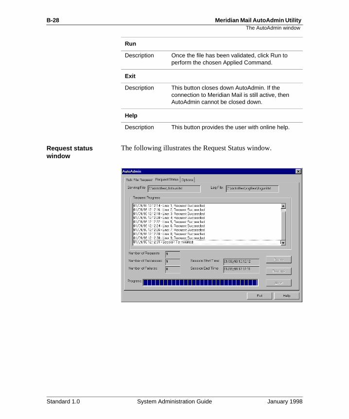
B-28 Meridian Mail AutoAdmin Utility The AutoAdmin window
Request status window
The following illustrates the Request Status window.
Run
Description Once the file has been validated, click Run to perform the chosen Applied Command.
Exit
Description This button closes down AutoAdmin. If the connection to Meridian Mail is still active, then AutoAdmin cannot be closed down.
Help
Description This button provides the user with online help.
Standard 1.0 System Administration Guide January 1998
Meridian Mail AutoAdmin Utility B-29The AutoAdmin window
the
Field descri ptions This table describes the boxes and buttons associated with request status window.Serving File
Description This box provides the user with the path and name of the file that is presently being run by Bulk File Request and the applied command. If no file is being run, “No file specified” appears in the box.
Default None
Log File
Description This box provides the user with the log file that is used to store verification, errors, and run data. If no file is being used to log the events, “No file specified” appears in the box.
Default None
Request Progress
Description This box provides the user with a view of the text file being processed. For each line of data, a report is issued. If errors occur, a return code (RC) is issued for that line. The window can display only 30 lines of requests at one time.
Default None
Number of Requests
Description Lists the total number of lines in the text file
Default 0
Number of Successes
Description Lists the lines that were processed without error
Default 0
Number of failures
Description Lists the number of lines not processed because of error
Default 0
Standard 1.0 System Administration Guide January 1998
B-30 Meridian Mail AutoAdmin Utility The AutoAdmin window
Session Start Time
Description Displays the time that the connection to Meridian Mail was established
Default Blank
Session End Time
Description Displays the time that the connection to Meridian Mail was terminated
Default Blank
Pause
Description This button is used if the administrator needs to stop but not end the processing of data.
Example: A large bulk add that is being processed can be paused if an error occurs that the operator wants to note.
Resume
Description This button is used to start processing that has been paused.
Abort
Description This button causes AutoAdmin to finish the request currently being processed, then shuts down the connection to Meridian Mail.
Progress
Description This box shows the user roughly where the process is at in terms of completing the entire text file.
Standard 1.0 System Administration Guide January 1998
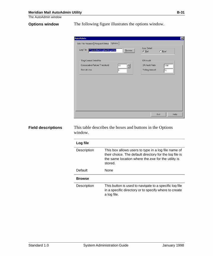
Meridian Mail AutoAdmin Utility B-31The AutoAdmin window
Options window The following figure illustrates the options window.
Field descri ptions This table describes the boxes and buttons in the Options window.
Log file
Description This box allows users to type in a log file name of their choice. The default directory for the log file is the same location where the.exe for the utility is stored.
Default None
Browse
Description This button is used to navigate to a specific log file in a specific directory or to specify where to create a log file.
Standard 1.0 System Administration Guide January 1998
B-32 Meridian Mail AutoAdmin Utility The AutoAdmin window
Log Detail - Full
Description When selected, this button provides a full description of errors that may occur during validation and processing.
Example: The following is a full error message:
Line 1;Tag:MN Data: RC: 20306 INF: Invalid length
Default Full
Log Detail - Brief
Description When selected, this button provides a brief description of information or errors that may occur during validation and processing.
Example: The following is a brief error message:
Line 13;Tag:D1 Data:5024 RC: 9528
Default Full
Tag Context Data File - Consecutive Failure Threshold
Description This box allows the user to provide a number that will stop the processing of a text file after a number of consecutive failures have occurred.
Example: If 10 is the threshold number, then the processing has to encounter 10 errors in a row, not failures adding up to 10.
Default 10
Range Use the cursor buttons to increase or decrease the number within a range of 1-100, or use the keyboard to type in a number between 1 and 10,000.
Tag Context Data File - Start at Line
Description Shows the line in the text file from which processing will commence.
Default 1
Range 1 to 32,767
Standard 1.0 System Administration Guide January 1998
Meridian Mail AutoAdmin Utility B-33The AutoAdmin window
DR Audit - DR Audit Rate
Description Displays the number of individual requests that have been processed by AutoAdmin before Meridian Mail undergoes a directory audit (DR audit). A directory audit is necessary to maintain optimum processing rates. Processing of the text file is deferred until the audit is complete.
The Meridian Mail directory will not be audited if there are 10 or fewer lines in the text file.
Default 1000
Range 500 to 2000
DR Audit - Polling Interval
Description Shows the time interval which AutoAdmin waits before checking on Meridian Mail to determine whether the directory audit is processing. The interval applies only after a DR Audit has begun. Once the audit is complete, AutoAdmin continues to process requests.
Note: The log file will be available once the directory audit is complete.
Default 10 minutes
Range 5 to 30 minutes
Standard 1.0 System Administration Guide January 1998
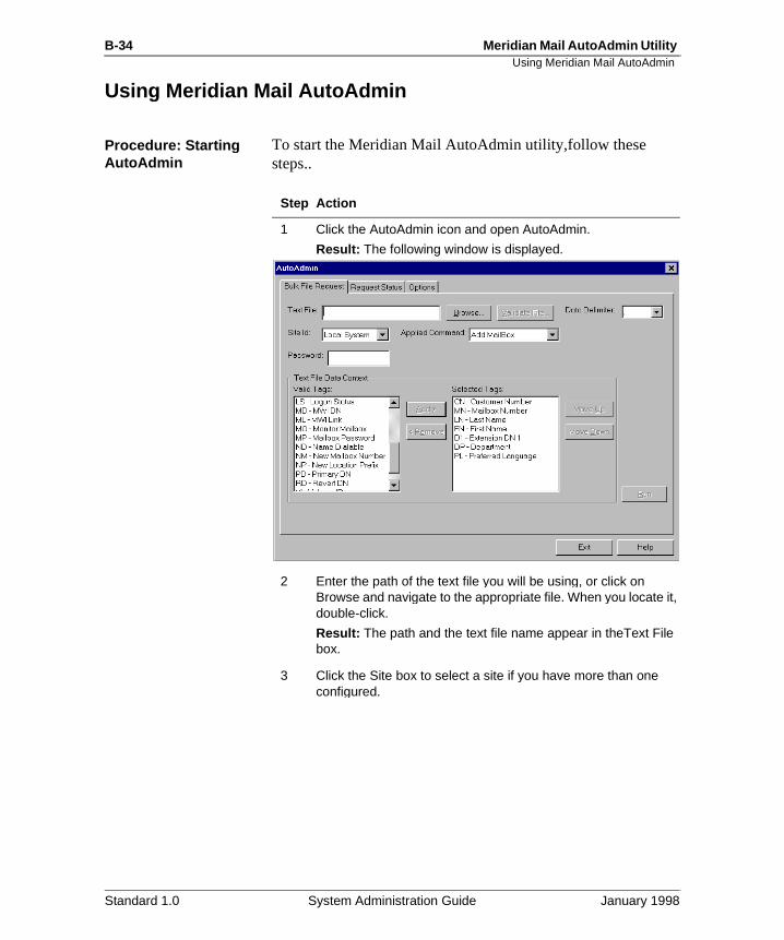
B-34 Meridian Mail AutoAdmin Utility Using Meridian Mail AutoAdmin
Usin g Meridian Mail AutoAdmin
Procedure: Startin g AutoAdmin
To start the Meridian Mail AutoAdmin utility,follow these steps..
Step Action
1 Click the AutoAdmin icon and open AutoAdmin.
Result: The following window is displayed.
2 Enter the path of the text file you will be using, or click on Browse and navigate to the appropriate file. When you locate it, double-click.
Result: The path and the text file name appear in theText File box.
3 Click the Site box to select a site if you have more than one configured.
Standard 1.0 System Administration Guide January 1998
Meridian Mail AutoAdmin Utility B-35Using Meridian Mail AutoAdmin
4 Click the Password box, and type in your Meridian Mail Customer Administrator password.
Note: A new password will be required every time the site ID is changed.
5 If you wish to keep a log file of all processing, click the Options tab and enter a log file name in the Log File box, then return to the Bulk File Request window.
6 Select the operation you want to perform in the Applied Command box. Use the decision table below to find the procedure you require.
Step Action
IF you want to ... THEN go to ...
Add mailboxes Adding mailboxes, page B-36
Add/replace mailboxes Adding and replacing mailboxes, page B-40
Remove mailboxes Removing mailboxes, page B-44
Update mailboxes Updating mailboxes, page B-48
Standard 1.0 System Administration Guide January 1998

B-36 Meridian Mail AutoAdmin Utility Using Meridian Mail AutoAdmin
in,
d nd
Procedure: Adding mailboxes
To add mailboxes through a bulk file request using AutoAdmfollow these steps.
Note: The following procedure assumes you have created anselected an appropriate text file that can be used to processmailbox information, that you have typed in your password, athat you have a logfile to record your events. Refer to the procedure “Starting AutoAdmin” on page B-34 before proceeding with the following instructions
Starting Point: Applied Command window.
Step Action
1 Select Add Mailbox.
2 Select the tags you require by first clicking on a desired tag in the Valid Tag box, then clicking the Add button.
Note: Mandatory tags for adding a mailbox are MN and LN. LN is not mandatory for adding guest mailboxes on an HVS system. For an NMS system, LP is required.
Result: Each tag is added to the Selected Tag box.
Standard 1.0 System Administration Guide January 1998
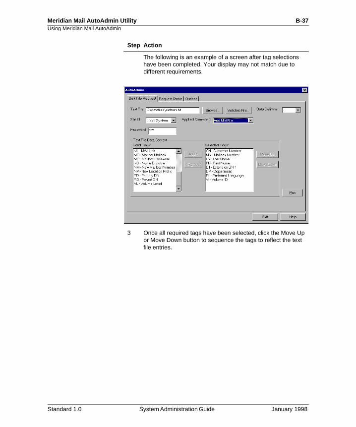
Meridian Mail AutoAdmin Utility B-37Using Meridian Mail AutoAdmin
The following is an example of a screen after tag selections have been completed. Your display may not match due to different requirements.
3 Once all required tags have been selected, click the Move Up or Move Down button to sequence the tags to reflect the text file entries.
Step Action
Standard 1.0 System Administration Guide January 1998
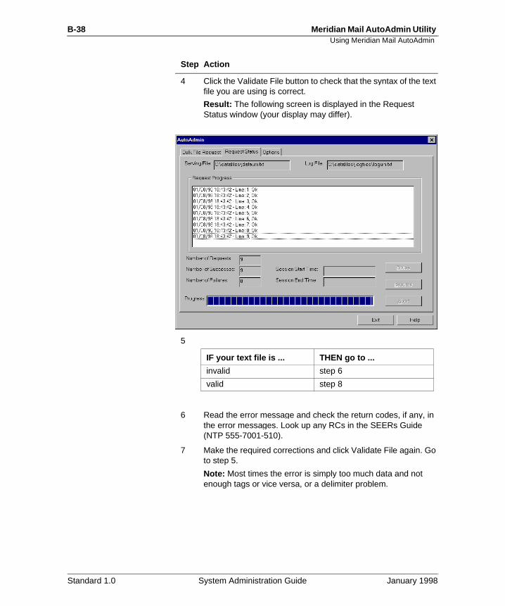
B-38 Meridian Mail AutoAdmin Utility Using Meridian Mail AutoAdmin
4 Click the Validate File button to check that the syntax of the text file you are using is correct.
Result: The following screen is displayed in the Request Status window (your display may differ).
5
6 Read the error message and check the return codes, if any, in the error messages. Look up any RCs in the SEERs Guide (NTP 555-7001-510).
7 Make the required corrections and click Validate File again. Go to step 5.
Note: Most times the error is simply too much data and not enough tags or vice versa, or a delimiter problem.
Step Action
IF your text file is ... THEN go to ...
invalid step 6
valid step 8
Standard 1.0 System Administration Guide January 1998
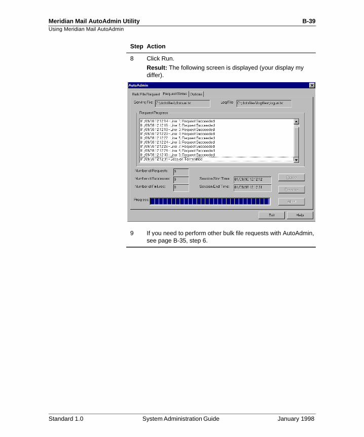
Meridian Mail AutoAdmin Utility B-39Using Meridian Mail AutoAdmin
8 Click Run.
Result: The following screen is displayed (your display my differ).
9 If you need to perform other bulk file requests with AutoAdmin, see page B-35, step 6.
Step Action
Standard 1.0 System Administration Guide January 1998
B-40 Meridian Mail AutoAdmin Utility Using Meridian Mail AutoAdmin
d
Procedure: Add/replace mailboxes
To add/replace mailboxes through a bulk file request using AutoAdmin, follow these steps.
Note: The following procedure assumes you have created anselected an appropriate text file that can be used to processmailbox information. Refer to the “Procedure: Starting AutoAdmin” on page B-34 before proceeding with the following instructions.
Starting Point: Applied Command window
CAUTION
Risk of data lossReplaced mailboxes cannot be recovered! Use this procedure with care.
Step Action
1 Select Add/Replace Mailbox.
2 Select the tags you require by first clicking on a desired tag in the Valid Tag box, then clicking the Add button.
Note: Mandatory tags for adding/replacing a mailbox are MN and LN. LN is not mandatory for adding guest mailboxes on an HVS system. For an NMS system, LP is required as well.
Result: The tag is added to the Selected Tag box.
Standard 1.0 System Administration Guide January 1998
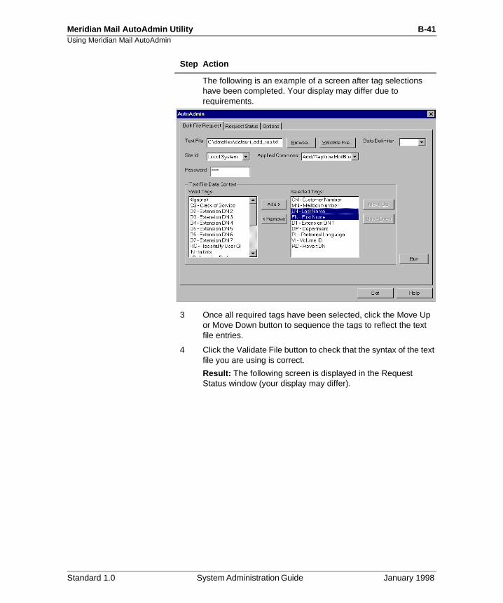
Meridian Mail AutoAdmin Utility B-41Using Meridian Mail AutoAdmin
The following is an example of a screen after tag selections have been completed. Your display may differ due to requirements.
3 Once all required tags have been selected, click the Move Up or Move Down button to sequence the tags to reflect the text file entries.
4 Click the Validate File button to check that the syntax of the text file you are using is correct.
Result: The following screen is displayed in the Request Status window (your display may differ).
Step Action
Standard 1.0 System Administration Guide January 1998
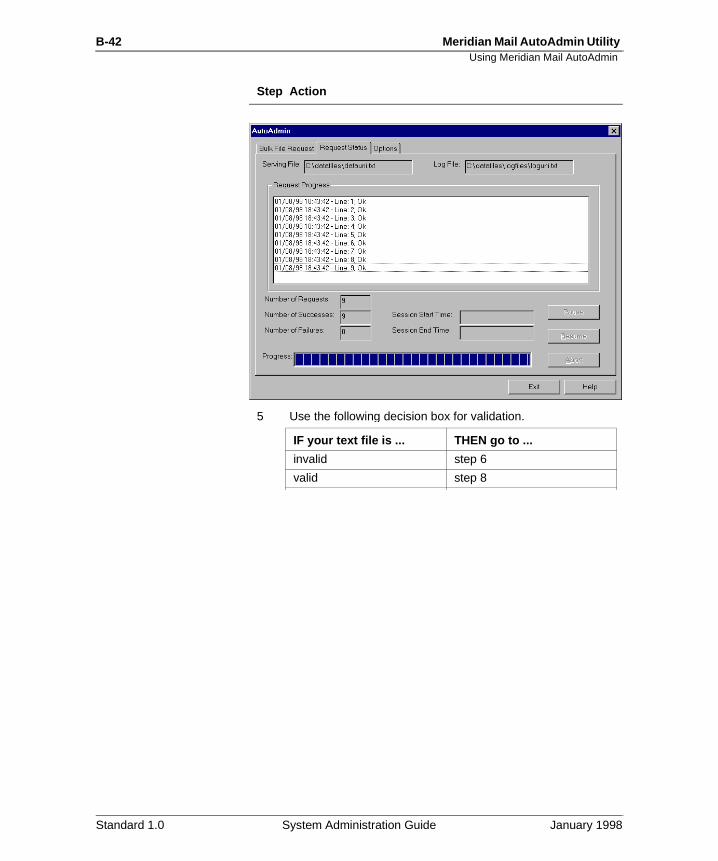
B-42 Meridian Mail AutoAdmin Utility Using Meridian Mail AutoAdmin
5 Use the following decision box for validation.
Step Action
IF your text file is ... THEN go to ...
invalid step 6
valid step 8
Standard 1.0 System Administration Guide January 1998
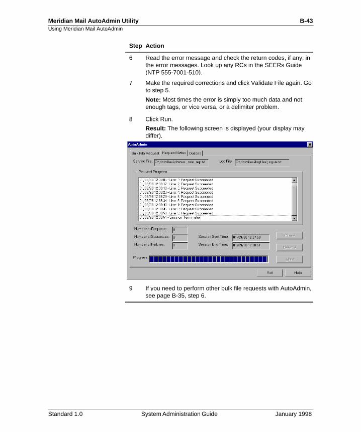
Meridian Mail AutoAdmin Utility B-43Using Meridian Mail AutoAdmin
6 Read the error message and check the return codes, if any, in the error messages. Look up any RCs in the SEERs Guide (NTP 555-7001-510).
7 Make the required corrections and click Validate File again. Go to step 5.
Note: Most times the error is simply too much data and not enough tags, or vice versa, or a delimiter problem.
8 Click Run.
Result: The following screen is displayed (your display may differ).
9 If you need to perform other bulk file requests with AutoAdmin, see page B-35, step 6.
Step Action
Standard 1.0 System Administration Guide January 1998
B-44 Meridian Mail AutoAdmin Utility Using Meridian Mail AutoAdmin
d
Procedure: Removin g Mailboxes
To remove mailboxes through a bulk file request using AutoAdmin, follow these steps.
Note: The following procedure assumes you have created anselected an appropriate text file that can be used to processmailbox information. Refer to the “Procedure: Starting AutoAdmin” on page B-34 before proceeding with the following instructions.
Starting Point: Applied Command window
CAUTION
Risk of data lossRemoved mailboxes cannot be recovered! Use this procedure with care.
Step Action
1 Select Remove Mailbox.
2 Select the MN tag. For an NMS system, select LP as well.
Note: If information other that the MN is entered in the text file, you can use the <Ignore> tag for each delimited piece of data in the text file.
Select <Ignore> tags as necessary.
Result: The tags are added to the Selected Tag box.
Standard 1.0 System Administration Guide January 1998
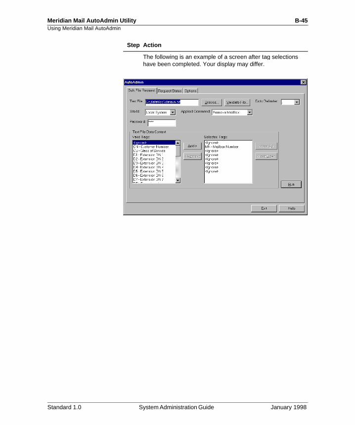
Meridian Mail AutoAdmin Utility B-45Using Meridian Mail AutoAdmin
The following is an example of a screen after tag selections have been completed. Your display may differ.
Step Action
Standard 1.0 System Administration Guide January 1998
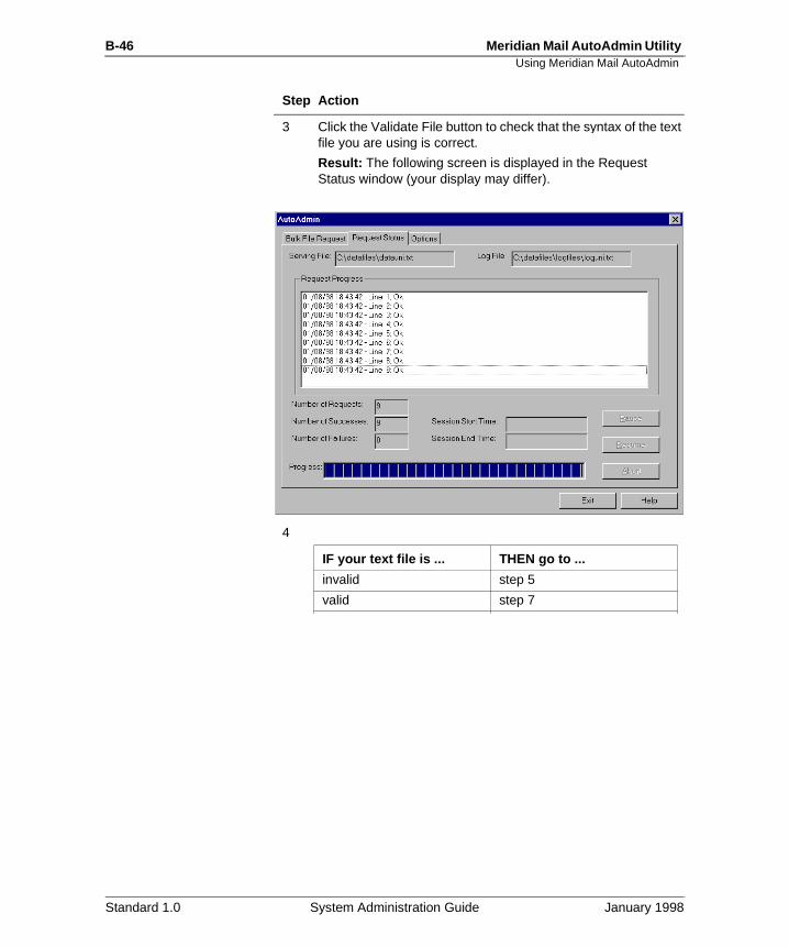
B-46 Meridian Mail AutoAdmin Utility Using Meridian Mail AutoAdmin
3 Click the Validate File button to check that the syntax of the text file you are using is correct.
Result: The following screen is displayed in the Request Status window (your display may differ).
4
Step Action
IF your text file is ... THEN go to ...
invalid step 5
valid step 7
Standard 1.0 System Administration Guide January 1998

Meridian Mail AutoAdmin Utility B-47Using Meridian Mail AutoAdmin
5 Read the error message and check the return codes, if any, in the error messages. Look up any RCs in the SEERs Guide (NTP 555-7001-510).
6 Make the required corrections and click Validate File again. Go to step 4.
Note: Most times the error is simply too much data and not enough tags or vice versa, or a delimiter problem.
7 Click Run.
Result: The following screen is displayed (your display may differ).
8 If you need to perform other bulk file requests with AutoAdmin, see page B-35, step 6.
Step Action
Standard 1.0 System Administration Guide January 1998
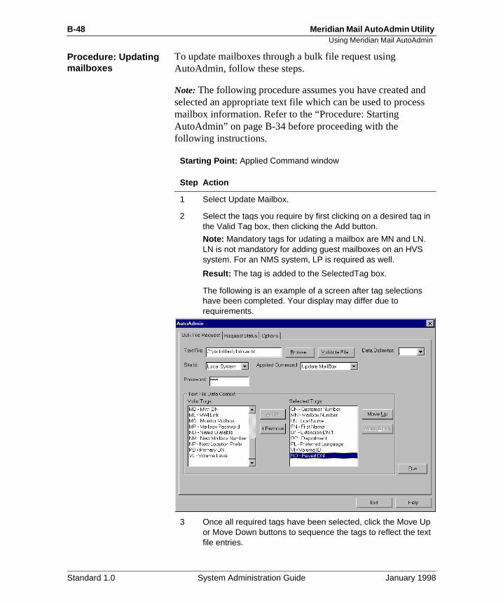
B-48 Meridian Mail AutoAdmin Utility Using Meridian Mail AutoAdmin
d s
Procedure: U pdatin g mailboxes
To update mailboxes through a bulk file request using AutoAdmin, follow these steps.
Note: The following procedure assumes you have created anselected an appropriate text file which can be used to procesmailbox information. Refer to the “Procedure: Starting AutoAdmin” on page B-34 before proceeding with the following instructions.
Starting Point: Applied Command window
Step Action
1 Select Update Mailbox.
2 Select the tags you require by first clicking on a desired tag in the Valid Tag box, then clicking the Add button.
Note: Mandatory tags for udating a mailbox are MN and LN. LN is not mandatory for adding guest mailboxes on an HVS system. For an NMS system, LP is required as well.
Result: The tag is added to the SelectedTag box.
The following is an example of a screen after tag selections have been completed. Your display may differ due to requirements.
3 Once all required tags have been selected, click the Move Up or Move Down buttons to sequence the tags to reflect the text file entries.
Standard 1.0 System Administration Guide January 1998
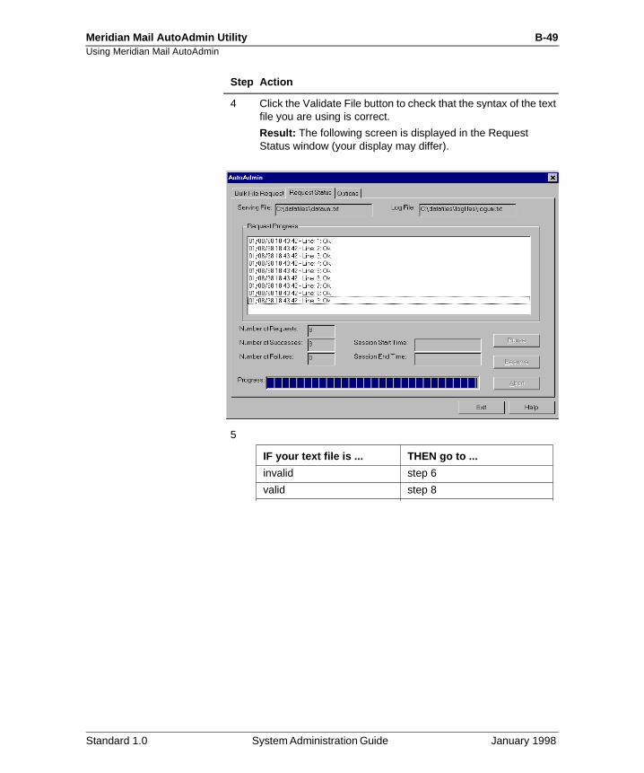
Meridian Mail AutoAdmin Utility B-49Using Meridian Mail AutoAdmin
4 Click the Validate File button to check that the syntax of the text file you are using is correct.
Result: The following screen is displayed in the Request Status window (your display may differ).
5
Step Action
IF your text file is ... THEN go to ...
invalid step 6
valid step 8
Standard 1.0 System Administration Guide January 1998
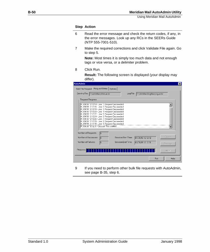
B-50 Meridian Mail AutoAdmin Utility Using Meridian Mail AutoAdmin
6 Read the error message and check the return codes, if any, in the error messages. Look up any RCs in the SEERs Guide (NTP 555-7001-510).
7 Make the required corrections and click Validate File again. Go to step 5.
Note: Most times it is simply too much data and not enough tags or vice versa, or a delimiter problem.
8 Click Run.
Result: The following screen is displayed (your display may differ).
9 If you need to perform other bulk file requests with AutoAdmin, see page B-35, step 6.
Step Action
Standard 1.0 System Administration Guide January 1998
Meridian Mail AutoAdmin Utility B-51Troubleshooting
Rs
t-
Troubleshootin g
Overview In general, if any problems with processing the text files, theuser is provided with return codes that are located in the SEEGuide (NTP 555-7001-510).
Start-up problems The following information provides possible solutions to starup problems in AutoAdmin.
AutoAdmin does not start u p properlyCheck the AutoAdmin folder on your PC, and open it. The following files should be in it:
• cmadf.txt
• cma.dll
• datafile.dll
• Gcl52fw.dll
• pctc.dll
• poweradm.exe
If any of these files are missing from the AutoAdmin folder, reinstall AutoAdmin.
Troubleshooting The following table provides remedies to problems with AutoAdmin start-up.
Symptom Error indication Remedy
AutoAdmin does not start up properly
During start-up, an error box with “data file failure” message appears.
Reinstall AutoAdmin.
Program starts with error box message: “A required .DLL file, xxx.DLL not found”.
Reinstall AutoAdmin.
Cannot start AutoAdmin or application with no content
Close other Windows applications.
Standard 1.0 System Administration Guide January 1998
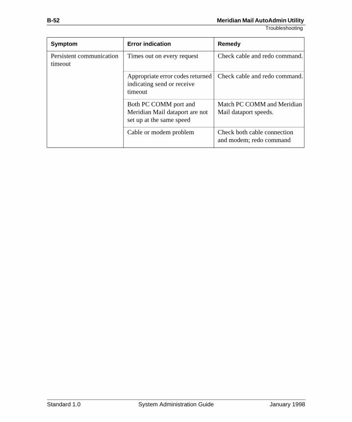
B-52 Meridian Mail AutoAdmin Utility Troubleshooting
nd.
.
Persistent communication timeout
Times out on every request Check cable and redo comma
Appropriate error codes returned indicating send or receive timeout
Check cable and redo command
Both PC COMM port and Meridian Mail dataport are not set up at the same speed
Match PC COMM and Meridian Mail dataport speeds.
Cable or modem problem Check both cable connection and modem; redo command
Symptom Error indication Remedy
Standard 1.0 System Administration Guide January 1998
Index
AACCESS
adding a VSDN, 24-36class for VSDN, 24-36
accesses to services, 31-13numbers of, 31-27
ACD DNin CAT, 28-52
Add Local Voice User screenaccessing, 8-11
adding, 24-16addressing by name, 20-40administration context
setting default for NMS, 8-9administration menus
choosing items from, 2-30administration screens
layout of, 2-31moving around in, 2-33selecting an entire line, 2-37
administrator capabilityenabling for mailboxes, 26-19locate users with, 8-60
AdminPlus passwordchanging, 16-8
agent queuesadding agents to a queue, 23-58configuring (high-level procedure), 23-36creating, 23-53modifying the CAT after moving agents, 23-64modifying the MAXP value, 23-57moving agents, 23-62removing agents, 23-63
alarmsdescription of types, 29-9
silencing, 29-13status of, 28-12, 29-10
allocated portsnumber of, 28-51
AMISact on AMIS initiator tone, 25-9adding a VSDN, 24-29applying restriction/permission lists, 6-121connect time, 31-39messages
failed attempts, 31-39number of messages delivered, 31-38number of messages received, 31-38open network messages
allowing users to receive, 26-28, 26-46allowing users to send, 26-28, 26-47restriction/permission lists, 26-29, 26-47
statistics, 31-38AMIS networking detail report
analyzing, 31-40announcements
adding a VSDN, 24-41finding, 22-11maximum prompt sizes, 25-8recording, 5-44
announcing callers, 26-40area/city code
for local system, 17-35translation tables, 17-63
assigning, 6-15classes of service to users, 26-64
assigning classes of service to the system, 13-14, 26-49
attendant DNmodifying, 13-17
audit trail dataenabling collection of, 31-23, 33-7
Standard 1.0 System Administration Guide January 1998
Index-2
number of days stored, 31-23number of days to store, 33-6stopping collection of, 33-6when to stop collection, 31-23
audit trail reportsfax on demand
analyzing, 33-37, 33-43generating, 33-33printing, 33-34
authorization code conditionally laston the M1
implementing, 6-63authorization codes
on the M1implementing, 6-24
AutoAdmin, 4-36, 13-11Bulk file request window, B-25Connecting Meridian Mail and the PC, B-3Installation procedure, B-5Modem Commands window, B-14Options window, B-31PC minimum hardware requirements, B-4Procedure
Add/replace mailboxes, B-40Adding a connection to a Meridian Mail
system procedure, B-16Changing settings in Configurator, B-17Changing the modem settings, B-18Removing a connection to a Meridian Mail
system, B-20Starting AutoAdmin, B-34Updating mailboxes, B-48
Request status window, B-28Supported platforms, B-3System configuration, B-4Upgrade procedure, B-10
AutoAdmin Configurator, B-12autologon
for hospitality voice messaging, 24-19automatic logon to mailboxes, 26-18, 26-36automatic play of user messages, 26-20
Bbackups
checking status of, 15-51deleting a scheduled backup, 15-45scheduling, 15-44
selectiveof all multimedia services, 15-35of all users, 15-25of all users in a department, 15-33of all users in a particular COS, 15-31of all users on a volume, 15-29of individual multimedia services, 15-37of individual users, 15-27restoring from, 15-56
to diskpartial, 15-40
to tapefull, 15-19partial, 15-21
basic service channelsfeatures support by, 23-15
basic service session profile, 24-81billing DN
defining, 20-52how used, 20-51
broadcast mailboxdescription, 20-47personal verification
description, 5-5recording, 5-37, 20-49
setting up, 20-49broadcast messages
allow users to compose and send, 26-19, 26-37locate mailboxes with broadcast capability, 8-59location-specific broadcast messages, 5-40, 5-41network broadcast messages, 5-39, 5-41, 26-19
locate mailboxes with capability, 8-60recording and sending, 5-41
bulk provisioningdata sets
assembling, 34-11copying to tape, 34-31creating, 34-17deleting, 34-25modifying, 34-19printing, 34-23printing a list of, 34-24viewing, 34-22
data sets from tape, 34-41printing data conflicts, 34-46viewing data conflicts, 34-45
Standard 1.0 System Administration Guide January 1998
Index-3
business hours default, 25-9busy
notifying callers of, 26-21, 26-37
Ccalculating centi-call seconds, 30-27calculating required OM disk space, 31-16call answering, 23-18, 24-17
allowing login from, 26-36applying restriction/permission lists, 6-111call transferred to mailbox, 5-8disabling messages from, 26-38greetings played during, 5-7language prompts are played in, 20-17, 20-23messages
maximum length of, 26-22, 26-39no answer, 5-8user busy, 5-9
call answering greetingdescription, 5-4, 20-29recording, 20-30recording from a telset, 5-20
call backusing call sender, 20-60
enabling/disabling, 20-61call back dialing restrictions
for fax callback services, 24-104for fax item maintenance, 24-111
call back extension promptfor callback fax services, 24-102
call back fax delivery, 24-100call back number treatment
dial as entered, 24-76ESN, 24-77for callback fax services, 24-103for fax item maintenance, 24-111international, 24-75national, 24-75
call back optionsspecifying for fax services, 24-105
call forward all callson the M1
implementing, 6-41call forward external deny
on the M1implementing, 6-42
call forward to trunk access code
on the M1implementing, 6-43
call senderenabling, 26-41external
applying restriction/permission lists, 6-120description, 20-60enabling/disabling, 20-61restriction/permission lists, 26-24, 26-42
caller choice fax delivery, 24-100callers
announcing, 26-40capturing external CLIDs, 17-36cards
enabling/disabling, 28-27location, 28-24number, 28-24running diagnostics, 28-28status of, 28-21, 28-26
centi-call secondscalculating, 30-27
changing the display options, 21-9Channel Allocation Table
accessing, 28-48modifying, 28-59
channel allocation tablededicated channels
overview, 28-56channel capability
fax item maintenance, 24-110for session profiles, 24-93
channel usagestatistics, 31-23
channel usage detail reportanalyzing, 31-25
channelsdedicating because of mixed port types, 23-24dedicating to services, 23-26identifying installed channels, 23-20
checking the installed channels, 23-20choosing the default language, 20-17city code. See area/city codeclasses of service
adding, 26-10assigning to the system, 13-14, 26-49assigning to users, 8-21, 26-64backing up all users in a COS, 15-31conversion utility, 26-66
Standard 1.0 System Administration Guide January 1998
Index-4
converting from user models, 7-23creating a personal COS for a user, 8-22, 26-65deleting, 26-59finding, listing, printing, 26-51for dial pulse users, 26-12modifying, 26-54on the M1, 6-15personal, 8-22reassigning users, 8-73
CLIDsdefault translation, 17-36external
capturing, 17-36format of CLIDs to monitor, 6-130monitoring, 6-130, 6-159
code restrictionon the M1
implementing, 6-35collecting
audit trail data, 31-23, 33-7session trace data, 31-22traffic data, 31-21user usage data, 31-22
compose capabilityenabling, 26-44
composed messagesallowing users to receive, 26-23, 26-39maximum length, 26-16, 26-34
configuring the switchadding agents to a queue, 23-58configuring agent queues (high-level procedure), 23-36configuring dummy queues (high-level procedure), 23-37creating a dummy queue, 23-60creating an agent queue, 23-53high-level procedure, 23-33modifying the CAT after moving agents, 23-64modifying the MAXP value in the queue, 23-57moving agents (high-level procedure), 23-62removing agents, 23-63
controlled class of serviceon the M1
implementing, 6-31conversion utility
converting from user models to COS, 26-66
country codefor local system, 17-35
courtesy disableports, 28-18
courtesy down of system, 28-15courtesy enable
ports, 28-18cover sheet
customizingfor fax services, 24-108
for fax items, 24-103custom revert
applying restriction/permission lists, 6-107description, 8-26restriction/permission lists, 26-29, 26-48
custom session profile, 24-109customizing session profiles, 24-91
fax item maintenance, 24-112for fax items, time-of-day controllers, voice
menus, 24-95
Ddata conflicts
printing, 34-46viewing, 34-45
Data Port Configuration screenaccessing, 27-23
data portsprinting data port information, 27-47viewing, 27-25
data setsassembling, 34-11bulk provisioning from tape, 34-41copying to tape, 34-31creating, 34-17deleting, 34-25modifying, 34-19printing, 34-23printing a list of, 34-24viewing, 34-22
data storagepercent used, 14-11
dedicated portsblocking inbound calls, 23-40blocking outbound calls, 23-43creating fully dedicated ports, 23-49
Standard 1.0 System Administration Guide January 1998
Index-5
dedicating channelsbecause of mixed port types, 23-24to services, 23-26
dedicating ports. See dedicating channelsdefault administration context
setting, 8-9default dialing prefixes
configuring, 17-37default language
choosing, 20-17multilingual systems, 20-13secondary, 20-19
DefinitionAdd mailbox, B-23Add/replace mailbox, B-23Remove mailbox, B-24Update mailbox, B-24
Definitions of the applied commands, B-23delaying delivery of voice messages, 20-40deleting read messages, 20-57delivery of network messages
delivery priorities, 20-53delivery option
for fax services, 24-100delivery to non-user
applying restriction/permission lists, 6-118enabling in COS, 26-27, 26-45
detail outcalling audit trail reportanalyzing, 33-28
diagnosticsanalyzing results of, 28-82changing the schedule, 28-81for a disk or disk pair, 28-72for cards, 28-28start time, 28-79
dial as entered call back number treatment, 24-76, 24-103dial pulse
support for, 26-35dialing by name, 20-40dialing prefixes
configuring defaults, 17-37dialing restrictions
for fax callback services, 24-104for fax item maintenance, 24-111on the M1
assigning, 6-15
dialing translationstroubleshooting, 17-77
dialing translations. See also translation tablesdirectory entry users
adding, 10-7deleting, 10-18description, 7-9finding, 10-12modifying, 10-16printing, 10-15recording a personal verification, 10-8viewing, 10-16viewing a list of, 10-14
DISAon the M1
implementing, 6-84disabing
remote terminal access (non-EC), 3-17disabling
cards, 28-27disk shadowing, 28-68dsp ports
in range mode, 28-43in single mode, 28-41
external call sender, 20-61mailboxes, 6-144name dialing and name addressing, 20-44nodes, 28-17ports
with courtesy enable, 28-18remote terminal access (EC), 3-22the system, 28-15unused mailboxes, 6-148
disk, 28-66diagnostics, 28-72status of prime disk, 28-66
disk backups, 15-40disk capacity
checking, 14-12disk number
for unshadowed systems, 28-66disk pair
diagnostics, 28-72status of, 28-67synching, 28-70
disk pair numberfor shadowed systems, 28-66
Standard 1.0 System Administration Guide January 1998
Index-6
disk shadowingdisabling, 28-68disk pair number, 28-66pair status, 28-67re-enabling, 28-70status of shadow disk, 28-67
disk spacecalculating requirements for OMs, 31-16
disk statuschecking, 28-63
disk usagechecking, 14-12statistics, 31-53
disk usage detail reportanalyzing, 31-54
display optionschanging, 21-9
distributionof volumes across nodes, 14-7
distribution listsadding, 11-14deleting, 11-27description, 7-10finding, 11-19listing, 11-19modifying, 11-23personal vs. system, 7-10prefix for personal lists, 20-46printing, 11-25recording a title, 11-15
DSP Port Status screenaccessing, 28-31
dsp portsdetailed view of status, 28-38disabling/enabling in range mode, 28-43disabling/enabling in single mode, 28-41location of, 28-36status, 28-14status field, 28-36viewing status of, 28-31
dual language promptingconfiguring for call answering, 20-23description, 20-19enabling in COS, 26-17secondary default language, 20-19
dummy queuesconfiguring (high-level procedure), 23-37creating, 23-60
duration of mailbox lockout, 26-37
Eeconomy delivery of networked messages, 20-53enabling
call sender, 26-41cards, 28-27compose capability, 26-44delivery to non-user, 26-27, 26-45disabled mailboxes, 8-92dsp ports
in range mode, 28-43in single mode, 28-41
external call sender, 20-61mailboxes (MMUI), 6-144mailboxes (VMUIF), 6-145name dialing and name addressing, 20-44nodes, 28-17ports
with courtesy disable, 28-18remote notification, 26-28, 26-45traffic data collection, 31-21update logging, 25-9
end timefor traffic period, 31-21
enhanced controlled class of serviceon the M1
implementing, 6-32entering information in fields, 2-36Enterprise networking
act on Enterprise initiator tone, 25-9adding a VSDN, 24-34sharing a DN with a voice service, 24-35sharing a DN with AMIS, 24-34
error messagesdescription, 2-41
escalating SEERs, 29-25ESN call back number treatment, 24-77, 24-103ESN dialing
default prefix, 17-35exchange codes
in translation tables, 17-63expiry date
for temporary absence greetings, 8-90
Standard 1.0 System Administration Guide January 1998
Index-7
expiry warningfor mailbox passwords, 6-127
express messagingadding the VSDN, 24-16applying restriction/permission lists, 6-111language prompts are played in, 20-17, 20-20mailbox ID, 24-15
extension dialingapplying restriction/permission lists, 6-113restriction/permission lists, 26-29
extension DNs, 8-24defining, 8-33
external call senderapplying restriction/permission lists, 6-120description, 20-60enabling/disabling, 20-61restriction/permission lists, 26-24, 26-42
external CLIDscapturing, 17-36
external greetingshow used in call answering, 5-7
external logondisabling, 6-128
external usersallowing users to send messages to, 26-25, 26-44
Ffailed disk
replacing, 28-69fax audit trail report
generating, 33-33printing, 33-34
fax delivery detail reportanalyzing, 31-50
fax item maintenanceadding a VSDN, 24-64call back number treatment, 24-111choosing a session profile, 24-64customizing the session profile, 24-112dialing restrictions, 24-111language of service, 24-65transmission error handling, 24-110
fax itemsadding a VSDN, 24-62choosing a session profile, 24-61customizing a session profile, 24-95
maximum number of selections, 24-97page limit for fax selections, 24-97
fax on demandapplying restriction/permission lists, 6-115audit trail report
analyzing, 33-37, 33-43automatic cover sheet, 24-103call back dialing restrictions, 24-104, 24-111call back extension prompt, 24-102customizing a cover sheet, 24-108customizing the session profile for fax item
maintenance, 24-112fax activity revert DN, 24-98fax delivery option, 24-100generating an audit trail report, 33-33maximum number of fax selections, 24-97page limit for fax selections, 24-97page transmission error handling, 24-99, 24-110printing an audit trail report, 33-34sender fax number, 24-98, 24-110sender name display, 24-104specifying call back options in the session
profile, 24-105specifying fax service options in the session
profile, 24-100sponsor fax item ID, 24-98statistics, 31-48treat call back number as, 24-103, 24-111
fax selectionsmaximum number, 24-97
fax servicesfinding, 22-11
feature availabilityMeridian Mail platforms, 2-46MMUI and VMUIF, 2-49
featuressupported by basic service channels, 23-15supported by full-service multimedia channels, 23-17supported by full-service voice channels, 23-16verifying which are installed, 13-11
fieldsentering information in, 2-36selecting an option, 2-35
Standard 1.0 System Administration Guide January 1998
Index-8
,
filtering SEERs, 29-34by severity level, 29-31by type, 29-32by type and severity, 29-32
Find Local Voice Users screenaccessing, 8-49
Find Remote Voice Users screenaccessing, 9-28
findingservice definitions, 22-11VSDNs, 22-9
flexible feature codeson the M1
implementing, 6-33, 6-45forced charge account
on the M1implementing, 6-28
forcing regular password changes, 6-141full backups to tape, 15-19full mailboxes
calls rejected, 8-89warning threshold
defining, 20-56description, 20-55
full service portsmaximum number of, 28-51
full volumestopping collection of audit trail data, 33-6
full-service multimedia channelsfeatures supported by, 23-17
full-service multimedia session profile, 24-86, 24-89
full-service voice channelsfeatures supported by, 23-16
full-service voice session profile, 24-83function keys, 2-27
GGeneral Options screen
accessing, 13-3generating
user usage reports, 32-7getting help, 2-40greetings
call answering, 20-29recording from a telset, 5-20
externalfinding users with greeting recorded, 8-60
for remote sitesrecorded verification, 5-5
for VMUIF logindescription, 20-33recordin, 5-52recording, 20-34
internalfinding users with greeting recorded, 8-60
personaldescription, 5-4maximum length, 26-16, 26-34recording, 5-25
personal verificationdescription, 5-4recording for a local voice user, 8-34recording for a remote site, 5-35recording for distribution lists, 5-31recording for the broadcast mailbox, 5-37recording from a telset, 5-28recording from the administration terminal
5-29temporary absence
expiry date, 8-90finding users with greeting recorded, 8-61
greetings serviceadding a VSDN, 24-24
guest consolestatistics, 31-60
guest console statistics reportanalyzing, 31-61
HHacker Monitor, 6-151hardware
monitoring, 18-6hardware administration menu
accessing, 27-4hardware location, 28-66
of disk, 28-66header
replay with message, 26-40help (online), 2-40history file
on the M1implementing, 6-82
Standard 1.0 System Administration Guide January 1998
Index-9
holidays, 25-10hospitality
selecting user class, 8-43statistics, 31-57user class, 8-41
hospitality voice messagingadding the VSDN, 24-21adding the VSDN for the post checkout mailbox service, 24-22autologon, 24-19
Iincoming trunk group exclusion
on the M1implementing, 6-72
initial password changeenforcing, 6-134
installating a systemusing VMBA, A-17
installed featuresverifying, 13-11
integrated mailbox administration, A-5data translation tables, A-7
interface typevoice messaging, 26-31
interfacesfor the telset
description, 2-48internal call forward
on the M1implementing, 6-44
internal greetingshow used in call answering, 5-7
international call back number treatment, 24-75, 24-103
international dialingdefault prefix, 17-34
invalid logon attemptsmaximum number per mailbox, 6-127maximum number per session, 6-126, 6-127
invalid selectionsmaximum number for voice services, 24-93
Kkeeping copies of sent messages, 26-26keypad functions, 2-27
Llanguage of service
for fax item maintenance, 24-65for voice prompt maintenace, 24-52
languagessecondary default language, 20-19
defining, 20-24setting up, 20-17, 20-24user’s preferred, 8-42, 20-13
overriding, 20-17length of messages
maximum, 26-16, 26-34limited access password
on the M1implementing, 6-78
limited access to overlayson the M1
implementing, 6-77link
status of, 28-12listing
classes of service, 26-51local area/city code, 17-35local country code, 17-35local dialing
default prefix, 17-34local system defaults
configuring, 17-37local voice users
adding, 8-6setting NMS administration context, 8-9
adding large numbers ofguidelines, 7-22
assigning to defined COSs, 8-21checking status, 8-86creating a personal COS, 8-22creating a remote notification schedule
from the administration terminal, 8-37deleting, 8-97description, 7-7distributing evenly over volumes, 7-19entering user information, 8-18
Standard 1.0 System Administration Guide January 1998
Index-10
finding, 8-70hospitality user class, 8-41listing, 8-70modifying, 8-84moving from a volume, 7-20name dialing by external callers
allowing, 8-43number of, 14-12printing a list of, 8-70reassigning to another COS, 8-74recording a personal verification
from the administration terminal, 8-34selecting preferred language, 8-43shadowed systems
guidelines for adding, 7-21volume level, changing, 8-43without phones
creating a mailbox, 8-25Location Name, 8-16Location Prefix, 8-16location-specific broadcast messages, 5-40, 5-41locked out mailboxes
checking time of lockout, 8-88duration of lockout, 26-37
logging onfrom a MAT, 3-14from a remote terminal (EC), 3-21from a remote terminal (non-EC), 3-17from the main administration terminal, 3-11single terminal access
to M1 and Meridian Mail, 3-23login
allowing from call answering, 26-36login greeting
for VMUIFrecording/disabling, 5-52
logonto mailboxes
automatic, 26-18logon sessions
maximum invalid logon attempts, 6-126, 6-127Logon/Status screen
redrawing, 3-5logons
from external phonesdisallowing, 6-128
to mailboxesautomatic, 26-36
checking last logon time, 8-88invalid attempts, 8-56minimum days since, 8-56monitoring, 6-153
long distance dialingdefault prefix, 17-34
Mmailbox
calls rejected if full, 8-58mailbox ID
for express messaging, 24-15mailbox logons
language prompts are played in, 20-16, 20-22maximum invalid attempts per mailbox, 6-127maximum invalid attempts per session, 6-126,
6-127mailbox prompts
enabling delayed prompts, 26-16, 26-34mailbox thru-dialing
applying restriction/permission lists, 6-113restriction/permission lists, 26-29
mailboxesautomatic logon to, 26-18, 26-36broadcast
description, 20-47recording personal verification, 20-49setting up, 20-49
calls rejected if full, 8-89disabled
reenabling, 8-92disabling, 6-144enabling administrator capability, 26-19enabling broadcast capability for, 26-19, 26-37for users without phones, 8-25lockout duration, 26-37mailbox to monitor, 6-152maximum invalid logon attempts, 6-127modifying security settings, 6-146monitoring for logons, 6-153, 8-94number of, 14-12passwords, 6-128
changing from administration terminal, 8-93defining a prefix, 6-137defining minimum length, 6-138expiry warning, 6-127
Standard 1.0 System Administration Guide January 1998
Index-11
forcing change on first logon, 6-129, 6-134forcing regular changes, 6-141maximum days between passwords, 6-127minimum length, 6-128suppress telset display, 6-129suppressing telset display, 6-135time of last change, 8-90
reassigning to another user, 8-96reenabling (MMUI), 6-144reenabling (VMUIF), 6-145restricting offsite access, 6-147SEER trigger mailbox, 29-36time of last lockout, 8-88unused
disabling, 6-148volume level
changing, 8-43warning threshold for full mailboxes
defining, 20-56description, 20-55
main menu, 2-6maximum length
of call answering messages, 26-22, 26-39maximum read message retention
defining, 20-58description, 20-57
MAXPmodifying its value in the queue, 23-57
menu itemsnumber of accesses, 31-27
menuschoosing items from, 2-30layout of, 2-28
Meridian Mail AutoAdmin, 4-36, 13-11Meridian Mail AutoAdmin installation, B-5Meridian Mail database
synchronizing with Meridian 1, A-9Meridian Mail Hacker Monitor, 6-151Meridian Mail hardware
monitoring, 18-6Meridian Mail menus
choosing items from, 2-30layout of, 2-28
Meridian Mail platformsfeature availability, 2-46
Meridian Mail screenslayout of, 2-31moving around in, 2-33
selecting an entire line, 2-37Meridian Mail telset interfaces
description, 2-48Meridian networking
adding a VSDN, 24-31Meridian networking. See also networkingmessage addressing by name, 20-40message delivery priority
defining, 20-54description, 20-53
message headerplaying back, 26-40
message lengthmaximum, 26-16, 26-34
message waiting indicationDN
defining, 8-33description, 8-29
setting options, 26-23, 26-39messages
allowing users to compose and send, 26-44allowing users to send to external users, 26-25,
26-44AMIS
failed attempts, 31-39number delivered, 31-38number received, 31-38
AMIS open networkallowing users to receive, 26-28, 26-46allowing users to send, 26-28, 26-47restriction/permission lists, 26-29, 26-47
broadcastrecording and sending, 5-41
call answeringmaximum length, 26-22, 26-39
composedallowing users to receive, 26-23, 26-39
enabling automatic playback, 26-20from call answering
disabling, 26-38how long to keep once listened to, 26-25, 26-43networking
failed attempts, 31-34number delivered, 31-32number received, 31-32
playbackskip to first new message, 26-40
playing header, 26-40
Standard 1.0 System Administration Guide January 1998
Index-12
retain copy of sent ones, 26-26setting message waiting indication option, 26-23, 26-39that have been listened to
when to delete, 20-57unsent
treatment of, 26-44MMUI
description, 2-48feature availability, 2-49
modifying the CAT after moving agents, 23-64monitoring
CLIDs, 6-130, 6-159specifying format, 6-130
mailbox logons, 6-153, 8-94Meridian Mail hardware, 18-6Meridian Mail operation, 18-4thru-dials, 6-130, 6-156
monitoring periodfor system accesses, 6-129, 6-152
moving agents (high-level procedure), 23-62multilingual systems
default language, 20-13overriding user’s preferred language, 20-17user’s preferred language, 20-13
multimedia channelsfeatures supported by, 23-17
multimedia portsminimum number of, 28-51
multiple administration terminals, 2-44logging on from, 3-14password
changing, 16-6multiple appearance DNs
support for, 7-12multi-user login
on the M1implementing, 6-80
MWI DN. See message waiting indication DN
Nname dialing
by external callers, 8-41allowing, 8-43
name dialing and name addressingdescription, 20-40enabling/disabling, 20-44prefix, 20-41
name displayof sender
for fax services, 24-104national call back number treatment, 24-75, 24-103navigating through screens, 2-33NCOS facility restriction level
on the M1implementing, 6-57
network broadcast messages, 5-6, 5-39, 5-41locate mailboxes with capability, 8-60network broadcast capability, 26-19
network speed callon the M1
implementing, 6-59network usage, 31-33networking
economy delivery, 20-53failures to send messages, 31-34message delivery priority
defining, 20-54description, 20-53
network usage, 31-33number of messages delivered, 31-32number of messages received, 31-32remote sites
recorded verification, 5-5recording a personal verification for, 5-35
standard delivery, 20-53statistics, 31-32
networking detail reportanalyzing, 31-35
new flexible code restrictionon the M1
implementing, 6-37new messages
skip to first, 26-40NMS
location name, 8-16location prefix, 8-16location-specific broadcast messages, 5-40, 5-41setting default administration context, 8-9
nodestatus, 28-13
Standard 1.0 System Administration Guide January 1998
Index-13
,
,
Node Configuration screenaccessing, 27-7
nodesdisabling/enabling, 28-17printing node information, 27-47type, 28-13viewing the node configurations, 27-10
notification of specific SEERs, 29-37notifying callers of busy line, 26-21, 26-37
Ooffsite access
to mailboxesrestricting, 6-147
online help, 2-40operational measurements
calculating disk space requirements, 31-16setting options, 31-24
Operational Measurements menuusing, 31-14
outcallingstatistics, 31-42
outcalling audit trail reportdetail
analyzing, 33-28generating, 33-13summary
analyzing, 33-18outcalling detail report
analyzing, 31-45out-of-service diagnostics
running, 28-28
Ppage limit
for fax selections, 24-97page transmission error handling
for fax item maintenance, 24-110paging through screens, 2-33partial backups to disk, 15-40partial backups to tape, 15-21password control
on the M1implementing, 6-75
password prefix, 6-126
passwordsAdminPlus
changing, 16-8for mailboxes
changing from administration terminal, 8-93defining a prefix, 6-137defining minimum length, 6-138expiry warning, 6-127forcing change on first logon, 6-129forcing regular changes, 6-141forcing users to change, 6-134maximum days between changes, 6-127minimum length, 6-128minimum number changes before repeats
6-128suppress telset display, 6-129suppressing display, 6-135time of last change, 8-56, 8-90
for MATschanging, 16-6
for remote activation, 24-54system administration
changing, 3-9, 16-3minimum length, 16-7recovering, 3-10setting for first time, 3-7
personal classes of service, 8-22creating, 26-65
personal distribution listsauto delete of invalid addresses, 26-20defining a prefix, 20-46
personal greetingsdescription, 5-4how used in call answering, 5-7locate mailboxes without greetings recorded
8-59maximum length, 26-16, 26-34recording, 5-25
personal verificationsallowing users to change their own, 8-61, 26-15, 26-33description, 5-4for broadcast mailbox
description, 5-5recording, 5-37, 20-49
for directory entry users, 10-8
Standard 1.0 System Administration Guide January 1998
Index-14
for distribution listsdescription, 5-5recording, 5-31
for local voice usersrecording, 8-34
for remote voice usersrecording, 9-19
how used in call answering, 5-7recording
from a telset, 5-28from the administration terminal, 5-29
playback of messagesautomatic, 26-20playing message header, 26-40
playback speed, 20-62port names
for printersmodifying, 13-21
portscourtesy disable/enable, 28-18full service
maximum number of, 28-51maximum number of, 28-50number currently allocated, 28-51viewing capability in CAT, 28-54viewing types in CAT, 28-53
ports, dedicating. See channelspost checkout mailbox service
adding the VSDN, 24-22preferred language
for local voice usersselecting, 8-43
preferred language of useroverriding, 20-17
prefixesdefault dialing prefixes
configuring, 17-37for ESN dialing, 17-35for exchange codes in translation table, 17-63for exchange codes not in translation table,
17-63for international dialing, 17-34for local dialing, 17-34for long distance dialing, 17-34for mailbox passwords, 6-126
defining, 6-137for personal distribution lists
defining, 20-46
name dialing and name addressing, 20-41NMS location, 8-16personal distribution list
description, 20-46primary DN, 8-24, 8-31prime disk
status of, 28-66printer port names
modifying, 13-21printers
changing SEER printer port name, 29-41Procedure
Removing Mailboxes, B-44prompt played during call answering, 5-8, 5-9prompts
enabling delayed mailbox prompts, 26-16, 26-34playing in two languages, 26-17
Qqueues
adding agents to a queue, 23-58configuring agent queues (high-level procedure), 23-36configuring dummy queues (high-level procedure), 23-37creating a dummy queue, 23-60creating an agent queue, 23-53modifying the CAT after moving agents, 23-64modifying the MAXP value, 23-57moving agents, 23-62removing agents, 23-63
Rread messages
how long to keep on system, 20-57retention period, 26-25, 26-43
redrawingLogon/Status screen, 3-5
reenablingdisabled mailboxes, 8-92mailboxes (MMUI), 6-144mailboxes (VMUIF), 6-145
Standard 1.0 System Administration Guide January 1998
Index-15
rejected callsfor full mailboxes, 8-89
remapping SEERs, 29-19remote activation
adding a VSDN, 24-54password, 24-54
remote notificationapplying restriction/permission lists, 6-116enabling in COS, 26-28, 26-45finding users with capability, 8-63schedules
creating from the administration terminal, 8-37
remote sitesrecorded verification, 5-5recording a personal verification for, 5-35
remote terminal (EC)logging on from, 3-21
remote terminal (non-EC)logging on from, 3-17
remote terminal accessdisabling (EC), 3-22disabling (non-EC), 3-17
remote voice usersadding
using bulk provisioning, 9-24using Enterprise Networking, 9-21using User Administration, 9-17
description, 7-8finding, 9-35finding and deleting, 9-46listing, 9-35manually deleting, 9-45modifying, 9-40, 9-44permanent, 9-8printing, 9-35recording a personal verification, 9-19temporary, 9-9viewing, 9-40, 9-44
removing agents, 23-63reports printer port
naming, 13-21restoring
from selective backup, 15-56restriction/permission lists
AMIS networking, 6-121AMIS open network messages, 26-29, 26-47applying to features, 6-101
call answering, 6-111custom revert, 6-107, 26-48custom revert DN, 26-29defining, 6-99delivery to non-user, 6-118express messaging
applying to, 6-111extension dialing, 6-113, 26-29external call sender, 6-120, 26-24, 26-42fax call back, 24-104fax item maintenance call back, 24-111fax on demand, 6-115mailbox thru-dialing, 6-113remote notification, 6-116thru-dial on the M1
applying to, 6-114thru-dial services, 6-109
restrictionson the M1
assigning, 6-15retention period
for read messages, 20-57, 26-25, 26-43revert
user’s custom DNrestriction/permission lists, 26-29
revert DNallowing users to define, 8-27defining, 8-33description, 8-26for ACCESS VSDNs, 24-36for fax services, 24-98prohibiting users from defining, 8-28user’s custom DN
restriction/permission lists, 26-48VMUIF mailbox lockout
defining, 20-46description, 20-45
revert to operatorapplying restriction/permission lists, 6-107
rotary phonessupport for, 26-35
routing controlon the M1
implementing, 6-69
Standard 1.0 System Administration Guide January 1998
Index-16
Ssame call fax delivery, 24-100scheduled backups
deleting, 15-45scheduling
disk diagnostics, 28-81scheduling a backup, 15-44screens
layout of, 2-31moving around in, 2-33selecting an entire line, 2-37
scrolling through screens, 2-33secondary default language
defining, 20-24secured messaging, 6-128security
for mailboxesmodifying settings, 6-146
on the M1assigning classes of service, 6-15authorization code conditionally last, 6-63authorization codes, 6-24call forward all calls, 6-41call forward external deny, 6-42call forward to trunk access code, 6-43code restriction, 6-35controlled class of service, 6-31DISA, 6-84enhanced controlled class of service, 6-32flexible feature codes, 6-33, 6-45forced charge account, 6-28history file, 6-82incoming trunk group exclusion, 6-72internal call forward, 6-44limited access password, 6-78limited access to overlays, 6-77multi-user login, 6-80NCOS facility restriction level, 6-57network speed call, 6-59new flexible code restriction, 6-37password control, 6-75routing control, 6-69single terminal access, 6-79station specific authorization codes, 6-26supplemental digit recognition, 6-51supplemental digit restriction, 6-54system speed call, 6-23
TGAR/TARG, 6-12time-of-day routing, 6-66user selectable call redirection, 6-46
SEER escalationsetting, 29-25
SEER printer portchanging the port name, 29-41naming, 13-21
SEER throttlingsetting, 29-22
SEERsbeing notified of specific SEERs, 29-37escalating severity level, 29-25filtering, 29-34filtering by severity level, 29-31filtering by type, 29-32filtering by type and severity, 29-32printing, 29-39remapping, 29-19retrieving from history file, 29-8setting SEER triggering, 29-37
selecting a line in a screen, 2-37selecting an option in a field, 2-35selective backup
of all multimedia services, 15-35of all users, 15-25of all users in a department, 15-33of all users in a particular COS, 15-31of all users on a volume, 15-29of individual multimedia services, 15-37of individual users, 15-27restoring from, 15-56
sender name displayfor fax services, 24-104
sender numberfor fax services, 24-98
sent messagesretain copy, 26-26
service accesses, 31-13number of, 31-27
servicesdedicating channels to, 23-26
services detail reportanalyzing, 31-29
services summary reportanalyzing, 31-15
session profilesbasic service, 24-81
Standard 1.0 System Administration Guide January 1998
Index-17
choosingfor fax item maintenance, 24-64for fax items, 24-61for time-of-day controllers, 24-48for voice menus, 24-45
creating a custom session profile, 24-91custom, 24-109customizing
for voice menus, fax items, time-of-day controllers, 24-95
customizing the session profile for fax item maintenance, 24-112
full-service multimedia, 24-86, 24-89full-service voice, 24-83maximum number of invalid selections, 24-93session time limit, 24-93specifying call back options, 24-105specifying fax service options, 24-100
session time limitfor voice services, 24-93
session trace dataenabling collection of, 31-22
shadow diskstatus of, 28-67
silencing alarms, 29-13single terminal access
on the M1implementing, 6-79
to M1 and Meridian Mail, 3-23skipping to first new message, 26-40softkeys, 2-39sort order for Choice of Services, 21-11sort order for Service Definition data menus, 21-11sort order for VSDN table, 21-10speed control, 20-62spoken name. See personal verificationssponsor fax item ID
for fax services, 24-98standard delivery of networked messages, 20-53start time
for traffic period, 31-21Start-up problems, B-51station specific authorization codes
on the M1implementing, 6-26
statusof backups
checking, 15-51of local voice users
checking, 8-86storage
amount used, 28-14of traffic data, 31-22
storage limitfor voice recordings, 26-15, 26-33
submailboxesmaximum number, 26-32
summary fax audit trail reportanalyzing, 33-37, 33-43
summary outcalling audit trail reportanalyzing, 33-18
supervised transfer delaymodifying, 13-10
supplemental digit recognitionon the M1
implementing, 6-51supplemental digit restriction
on the M1implementing, 6-54
suppressing display of telset passwords, 6-135suppressing telset display of passwords, 6-129SW7007, 6-147synching
disk pair, 28-70synchronizing
Meridian 1 and Meridian Mail databases, A-9system
disabling/activating, 28-15system accesses
monitoring period, 6-152monitoring period for, 6-129
system addressing lengthmodifying, 13-10
system administration passwordchanging, 3-9, 16-3recovering, 3-10setting for first time, 3-7
system distribution lists. See distribution listssystem name
changing, 13-7system number
changing, 13-7
Standard 1.0 System Administration Guide January 1998
Index-18
system speed callon the M1
implementing, 6-23system status, 28-11System Status screen
accessing, 28-8system time
changing, 16-10system volumes, 14-5
Ttape backups
full, 15-19partial, 15-21
tape drivescleaning, 18-9cleaning and maintaining, 15-52
TARGimplementing, 6-12
telset display of passwordssuppressing, 6-129
telset interfacesdescription, 2-48
temporary absence greetingsexpiry date, 8-90finding users with greeting recorded, 8-61how used in call answering, 5-7
terminal number, 28-52TGAR
implementing, 6-12The AutoAdmin window, B-25threshold
for full mailbox warning messagedefining, 20-56description, 20-55
throttling SEERs, 29-22thru-dial greetings
recording, 5-44thru-dial on the M1
applying restriction/permission lists, 6-114thru-dial services
adding a VSDN, 24-43applying restriction/permission lists, 6-109
thru-dialsmonitoring, 6-130, 6-156
timed deliverydescription, 20-40
time-of-day controllersadding a VSDN, 24-50customizing a session profile, 24-95
time-of-day routingon the M1
implementing, 6-66timeouts for voice services, 25-7toggling a user’s COS assignment, 8-73toggling between M1 and Meridian Mail, 3-23traffic data
enabling collection of, 31-21how long to store, 31-22how often to write to disk, 31-21
traffic periodend time, 31-21start time, 31-21
traffic reportsdescriptions, 31-5generating, 31-7
traffic statisticsCCS, 31-14, 31-15
transcription serviceadding a VSDN, 24-59defining a voice form ID, 24-58
translationCLIDs with unkown format, 17-36
translation tablesarea/city code, 17-63configuring, 17-64deleting, 17-67exchange codes, 17-63identifying requirements, 17-45prefix for exchange codes in table, 17-63prefix for exchange codes not in table, 17-63table number, 17-62troubleshooting, 17-77
transmission error handlingfax item maintenance, 24-110
Troubleshooting, B-51tutorials
for VMUIFdescription, 20-32recording, 5-50, 20-34
Standard 1.0 System Administration Guide January 1998
Index-19
,
UUCD groups
determining how many are needed, 23-28unsent messages
treatment of, 26-44unused mailboxes
disabling, 6-148uploading data
from Meridian Mail to M1, A-9user class
for hospitalityselecting, 8-43
hospitality, 8-41user flexible call redirection
on the M1implementing, 6-46
user modelsconverting from, 26-66converting to classes of service, 7-23
user usage dataenabling collection of, 31-22number of days to store, 31-23
user usage reportsanalyzing, 32-14generating, 32-7report analysis, 32-14selection criteria, 32-4selection screen, 32-2
user volumes, 14-6user’s preferred language, 20-13
overriding with default language, 20-17users. See local voice users, remote voice users,
or directory entry usersUsing Meridian Mail AutoAdmin, B-34
Vverifying location of voice services, 15-12View/Modify Local Voice User screen
accessing, 8-80, 8-81VMBA
installing a system with, A-17VMUIF
description, 2-48feature availability, 2-49
VMUIF introductory tutorialdescription, 20-32recording, 20-34recording/disabling, 5-50
VMUIF login greetingdescription, 20-33recording, 20-34recording/disabling, 5-52
voice channelsfeatures supported by, 23-16
voice formsadding a VSDN, 24-56adding a VSDN for the transcription service
24-59finding, 22-11making recordings, 5-44transcription service
definining a voice form ID, 24-58voice menus
adding a VSDN, 24-46customizing a session profile, 24-95finding, 22-11making recordings, 5-44number of menu item accesses, 31-27
voice messagingadding the VSDN, 24-13statistics, 31-19
voice messaging detail reportanalyzing, 31-21
voice messaging optionsconfiguring, 20-9defining for MMUI, 20-38defining for VMUIF, 20-39
Voice Messaging Options screenaccessing, 20-5
voice path diagnostics, 28-77maximum duration of, 28-80maximum number idle channels, 28-80
voice portsmaximum number of, 28-50
voice prompt maintenancelanguage of service, 24-52
voice prompt maintenance serviceadding a VSDN, 24-52
voice servicesbusiness hours default, 25-9enabling update logging, 25-9holidays, 25-10
Standard 1.0 System Administration Guide January 1998
Index-20
making recordings for, 5-44maximum number of invalid selections, 24-93maximum prompt sizes for announcements,
25-8maximum sizes for other recordings, 25-8modifying the voice services profile, 25-6session time limit, 24-93timeouts, 25-7verifying location of, 15-12
voice storagepercent used, 14-12
Volume and Select Backup screenaccessing, 14-10
volume levelfor mailboxes
changing, 8-43volumes
contents of, 14-5full
stopping audit trail data collection, 33-6how they are distributed across nodes, 14-7how they are named, 14-3size, 14-11system, 14-5user, 14-6
VSDN tableaccessing, 24-7sort order, 21-10
VSDNsACCESS, adding, 24-36AMIS networking, adding, 24-29announcements, adding, 24-41calculating how many you need, 23-29deleting, 24-120determining how many you need, 24-78Enterprise networking
adding, 24-34express messaging, 24-16fax item maintenance, adding, 24-64fax items, adding, 24-62finding, 22-9greetings service, adding, 24-24hospitality, adding, 24-21Meridian networking, adding, 24-31post checkout mailbox, adding, 24-22remote activation, adding, 24-54thru-dial services, adding, 24-43time-of-day controllers, adding, 24-50
transcription service, adding, 24-59viewing or modifying, 24-117voice forms, adding, 24-56voice menus, 24-46voice messaging, adding, 24-13voice prompt maintenance, adding, 24-52
Wwaiting messages
setting indication option for, 26-23, 26-39warning threshold for full mailboxes
defining, 20-56description, 20-55
Standard 1.0 System Administration Guide January 1998
List of Fields
Symbols, B-27#, 31-57#Expired Unread Messages, 31-57#Guests Checked In, 31-57#Guests Checked Out, 31-57#Messages (Unread, Read), 31-57#New Unread Messages, 31-57
AAbort, B-30ACCESS class, 24-36ACD DN, 28-52Act on AMIS/Enterprise Initiator Tone, 25-9Add, B-13Add>, B-27Administrator Capability, 8-60, 26-19Alarm Status, 28-12All Entries, 34-44Allocated, 28-51AMIS Open Network Restriction/Permission List, 26-29, 26-47Announce Caller, 26-40Announcement ID, 24-41Applied command, B-26Area/City Code, 17-63Attendant DN, 13-15Attributes (for ports with type = Data), 27-15Attributes (for ports with type = Device), 27-15Attributes (for ports with type = Voice or Multi), 27-16Auto Deletion of Invalid PDL Addresses, 8-61, 26-20Auto Logon, 8-59, 26-18, 26-36Auto Play, 26-20Autologon, 24-19
Standard 1.0 System Administration Guide January 1998
Fields-2
Automatic Cover Sheet, 24-103Average Length (in seconds), 31-14
BBackup Completed, 15-50Backup frequency, 15-43Backup Selected, 15-50Backup start time, 15-43Backup Started, 15-50Backup Volumes, 15-50Baud Rate, 27-29, 27-31, 27-33, 27-37, 27-39, 27-41, 27-43Billing DN, 20-51, 24-99, 24-110, 33-36Broadcast Capability, 8-59, 26-19, 26-37Broadcast Mailbox Number, 20-49Broadcast Mailbox Personal Verification (Voice), 20-49Browse, B-31Business Hours Default, 25-9
CCall Answering Greeting (Voice), 20-29Call Answering/Express Messaging Thru-Dial Restriction/Permission List Number, 6-129Call Back Dialing Restrictions, 24-104, 24-111Call Back Extension Prompt, 24-102Call Sender, 26-41Call Status, 33-16, 33-22, 33-36, 33-40Called DN, 33-36, 33-39Callers Notified of Busy Line, 26-21, 26-37Calls Rejected after Mailbox Full, 8-89Calls were Rejected after Mailbox Full, 8-58Cancel, B-15Capture External CLID with Unknown Format, 17-36Card, 27-8Card #, 28-24Card_Type, 27-13C-D-P, 27-13, 28-52C-D-P (location), 28-36Channel, 31-23Channel Capability Required, 24-93, 24-110Channel DN, 33-20, 33-39Check In, 31-60Check Out, 31-60Class of Service Name, 26-14, 26-31Class of Service Number, 26-13, 26-31Class of Service Selections, 13-13
Standard 1.0 System Administration Guide January 1998
Fields-3
l
CLID Format—External—CLIDs to Monitor, 6-130CLID Format—Internal—CLIDs to Monitor, 6-130CLIDs to Monitor, 6-158Collect Audit Trail Data, 31-23, 33-6Collect Traffic Data, 31-21Collect User Usage/Session Trace Data, 31-22Comment, 24-10Comments, 25-10Compose Capability, 8-59, 26-44Compose/Send AMIS Open Network Messages, 8-64, 26-28, 26-47Connect Time (mm:ss), 31-39, 32-12Connection, B-13Copy Mbox, 31-60COS, 8-54Created On, 34-38Creation Date, 34-30Custom Revert Restriction/Permission List, 26-29, 26-48Customer Number, 29-36
DData Conflicts, 34-44Data delimiter, B-26Data from tape, 34-44Data overwritten on destination, 34-44Data Port Location, 27-28Data Set Name, 34-15, 34-30, 34-38Date Format for Administration and Maintenance Reports, 13-18,
13-19Day of Month, 15-43Default Language, 20-13Default Language Overrides User’s Preferred Language for Cal
Answering, 20-14Default Message Delivery Priority, 20-53Default sort order for Service Definition data menus, 21-11Default sort order for VSDN Table data menus, 21-10Default Translation for CLID with Unknown Format, 17-36Delayed Prompts, 26-16, 26-34Delivery to Non-User Capability, 8-62, 26-27, 26-45Department, 8-18, 9-14, 10-5, 10-11Description, 27-24, B-13Device Name, 27-28Device Type, 27-24, 27-28Device/Target Phone Number, 33-20Dial Prefix, B-15Dial Pulse Support, 26-35Dial Suffix, B-15Disk (appears only on Unshadowed systems), 28-66
Standard 1.0 System Administration Guide January 1998
Fields-4
Disk Pair (appears only on Shadowed systems), 28-66Disk Used (mm:ss), 32-12Display Choice of Services/Menu Actions in, 21-11Display the List in MWI Status Format, 8-66DN, 24-10DR Audit - DR Audit Rate, B-33DR Audit - Polling Interval, B-33DSP Port Status, 28-14, 28-36Dual Language Prompting, 26-17
EEnable Update Logging, 25-9End Date, 25-10ESN Dialing, 17-35Exit, B-14, B-28Extension Dialing Restriction/Permission List, 26-29Extension DNs, 8-32, 9-15, 10-6, 10-11Extension Number (DN), 9-30External Call Sender Restriction/Permission List, 26-24, 26-42External Call-Sender Allowed, 20-60External Logon, 6-128External Personal Greeting Recorded, 8-60, 8-90
FFailures, 31-34, 31-39Fax Activity Revert DN, 24-98Fax Delivery Option, 24-100Fax Item ID, 24-62First Name, 8-17, 10-5, 10-10, 33-12For each menu item, the number of accesses are, 31-27Force Password Change on Initial Logon, 6-129
HHangup Prefix, B-15Hangup Suffix, B-15Help, B-14, B-15, B-28Holidays, 25-10hospitality statistics report
analyzing, 31-58Hospitality User Class, 8-41HWLOC, 28-66
Standard 1.0 System Administration Guide January 1998
Fields-5
IID, 31-27Include AMIS Network Usage, 32-5Include Local Usage, 32-5Include Meridian Network Usage, 32-5Incoming Avg Length (in seconds), 31-23Information to backup, 15-44Initialization, B-15Initials, 8-17Internal Greeting Recorded, 8-89Internal Personal Greeting Recorded, 8-60International Dialing, 17-34Invalid Logon Attempts, 8-87
JJ4, 27-14J5, 27-14
LLanguage of Service, 24-52, 24-65Last Access Time, 9-16Last Event, 28-12Last Name, 8-17, 9-14, 10-4, 10-10, 33-12Limit , 28-50Link Status, 28-12List Number, 11-12List Title, 11-13List Title Recorded (Voice), 11-13Local Area/City Code, 17-35Local Country Code, 17-35Local Dialing, 17-34Local Users, 34-16Location Name, 11-11Location Prefix, 11-11Lockout Duration, 26-37Lockout Revert DN, 20-45Log Detail - Brief, B-32Log Detail - Full, B-32Log File, B-29Log file, B-31Login from Call Answering, 8-58, 26-36Login Greeting (Voice), 20-33Long Distance Dialing, 17-34
Standard 1.0 System Administration Guide January 1998
Fields-6
MMailbox Full Warning Threshold (percentage), 20-55Mailbox ID, 24-15Mailbox Number, 8-16, 8-53, 9-13Mailbox Numbers, 11-13Mark Channel Faulty if Voice Path Diagnostics Fail, 28-79MaxFull, 28-51Maximum CA Message Length (mm:ss), 8-57Maximum Call Answering Message Length, 26-22, 26-39Maximum Days Permitted Between Password Changes, 6-127Maximum Delay for Timed Delivery (days), 20-42Maximum Duration of Voice Path Diagnostics (hh:mm), 28-80Maximum Invalid Logon Attempts Permitted per Mailbox, 6-127Maximum Invalid Logon Attempts Permitted per Session, 6-126Maximum Message Length, 26-16, 26-34Maximum Message Length (mm:ss), 8-57Maximum Number of Fax Selections, 24-97Maximum Number of Invalid Selections, 24-93Maximum Number of SubMailboxes, 8-57, 26-32Maximum Personal Greeting Length, 26-34Maximum Personal Greeting Length (mm:ss), 8-57Maximum Prompt Sizes for Announcements (mm:ss), 25-8Maximum Prompt Sizes for other voice recordings (mm:ss), 25-8Maximum Read Message Retention (days), 20-57MaxVoice, 28-50Message Length (Avg and Max), 31-20Message Length (mm:ss), 32-12Message Remote Notification Option, 8-63Message Trigger, 29-18Message Trigger Mailboxes, 29-36Message Waiting Indication DN, 8-32, 8-55Message Waiting Indication Options, 8-65, 26-23, 26-39Messages Created (EM/Ans and Log), 31-20Messages Delivered, 31-32, 31-38Messages Received, 31-32, 31-38Minimum Admin Password Length, 16-7Minimum Number of Days since Last Logon, 8-56Minimum Number of Days since Pswd Changed, 8-56Minimum Number of Idle Channels for Voice Path Diagnostics, 28-80Minimum Number of Invalid Logon Attempts, 8-56Minimum Number of Password Changes Before Repeats, 6-128Minimum Password Length, 6-128MinMulti , 28-51Modem, B-14Modified Date, 34-30Modify, B-14
Standard 1.0 System Administration Guide January 1998
Fields-7
Monitor All Thru-Dials during Monitoring Period, 6-130, 6-155Monitor CLIDs during Monitoring Period, 6-130, 6-158Monitor Mailbox during Monitoring Period, 6-152, 8-40Monitor this Service during Monitoring Period, 6-155Move down, B-27Move up, B-27
NName Dialable by External Callers, 8-41, 8-61, 9-15, 10-6Name Dialing and Name Addressing, 20-42Network Broadcast Capability, 8-60, 26-19Network Modem DN, 27-35Network Usage, 31-33Node, 27-8, 28-13Node Type, 28-66Number of Accesses, 31-13Number of Attempts, 31-42Number of Calls (Int and Ext), 31-19Number of Days of Audit Data stored, 31-23Number of days of Audit Data stored, 33-6Number of days of Traffic Data stored, 31-22Number of days of User Usage Data stored, 31-23Number of Economy Messages, 32-12Number of failures, B-29Number of Incoming Calls, 31-23Number of Mailboxes, 14-12Number of Messages, 32-12Number of New Attempts, 31-48Number of New Requests, 31-42, 31-48Number of Outgoing Calls, 31-23Number of requests, B-29Number of Retries, 31-48Number of Sessions, 32-11Number of Sessions (EM/Ans and Log), 31-19Number of Standard Messages, 32-13Number of Successes, 31-43, 31-48Number of successes, B-29Number of Urgent Messages, 32-13Number of Windows, 27-29
Standard 1.0 System Administration Guide January 1998
Fields-8
OOK, B-15OM Collection ACCESS Class, 31-23Outbound, 28-55Outcall Action, 33-24, 33-41Outcall Process, 33-21, 33-39Outgoing Avg Length (in seconds), 31-23
PPage Limit for Fax Selections, 24-97Page Transmission Error Handling, 24-99, 24-110Pair Status, 28-67Parity, 27-29Password, 24-54, B-27Password Expiry Warning (days), 6-127Password Last Changed, 8-90Password Prefix, 6-126Pause, B-30Personal Distribution List Prefix, 20-46Personal Greeting Recorded, 8-59, 8-89Personal Verific. Recorded, 10-14Personal Verification Changeable by User, 8-61, 26-14Personal Verification Recorded (Voice), 9-15, 10-6, 10-11Personal Verification Status, 8-65, 9-30Port, B-13Port Location, 27-24Port_Type, 27-14Preferred Language, 8-42, 8-64Prefix for exchange codes in the table, 17-63Prefix for Name Dialing and Name Addressing, 20-43Prefixes for exchange codes NOT in the table, 17-63Primary DN, 8-31Primary DN differs from MWI DN, 8-62Prime Status, 28-66Progress, B-30Prompt played During Call Answering, 26-21Provision remote users as, 34-38
RRead Message Retention (days), 26-25, 26-43Receive AMIS Open Network Messages, 8-64, 26-28, 26-46Receive Composed Messages, 8-59, 26-23, 26-39Receive Messages for Call Answering, 8-58, 26-38Re-Check In, 31-60
Standard 1.0 System Administration Guide January 1998
Fields-9
Remote Notification Capability, 8-62, 26-28, 26-45Remote Notification Keypad Interface, 8-64Remote Users, 34-39Remove, B-13Replay Header with Message, 26-40Report, 33-12Report End (mm/dd/yy), 32-6Report Start (mm/dd/yy), 32-6Report Start/End, 29-7, 33-13, 33-32Report Type, 33-32Reports Printer Port Name, 13-21Request #, 33-39Request Progress, B-29Resume, B-30Retain Copy of Sent Messages, 26-26Retry, 33-21, 33-39Revert DN, 8-32, 8-55, 24-36Run, B-28
SSchedule Diagnostics on the Following Days, 28-79SCN, 28-53Secondary Default Language, 20-19SEER Class, 29-7SEER Escalation Interval, 29-24SEER Escalation Threshold Count, 29-24SEER Filters, 29-33SEER Printer Output, 29-38SEER Printer Port Name, 13-20, 29-40SEER Severity Threshold, 29-33, 29-34SEER Throttle Interval, 29-22SEER Throttle Threshold Count, 29-21SEER Type, 29-7Selected Tags, B-27Selection Criteria, 32-4, 33-12Send Message via DNU if Mailbox Not Found, 8-62Send Messages to External Users, 26-25, 26-44Sender Fax Number, 24-98, 24-110Sender Name Display, 24-104Service, 24-10Service Accesses, 31-27Service Name, 31-13Services, 34-16Serving File, B-29Session end time, B-30Session Length (Avg and Max), 31-20Session Profile, 24-45, 24-48, 24-61, 24-64
Standard 1.0 System Administration Guide January 1998
Fields-10
Session start time, B-30Session Time Limit (minutes), 24-93Severity Level, 29-7Shadow Status, 28-67Shutdown Audit Trail at Volume Full (%), 31-23, 33-6Site, 31-32Site ID, B-26Skip to First New Message, 26-40Sort Choice of Services/Menu Actions by, 21-11Sorted, 32-5Speed, B-14Sponsor Fax Item ID, 24-98Start Date, 25-10Start Time, 25-10Status, 27-24, 34-31Storage Used, 28-14Storage used, 8-17Supervised Transfer Delay, 13-8Suppress Display of Telset Password, 6-129System Access Monitoring Period, 6-152System Access Monitoring Period from (hh:mm), 6-129System Addressing Length, 13-8System ID, B-12System Level Conflicts, 34-43System Name, 13-6System Number, 13-6System Status, 28-11
TTable ID, 17-62Tag Context Data File - Consecutive Failure Threshold, B-32Tag Context Data File - Start at Line, B-32Tape Label, 15-50Tape label, 15-44Target Phone Number, 33-13, 33-16Temporary Absence Greeting Expiry Date, 8-90Temporary Absence Greeting Recorded, 8-61, 8-90Text File, B-25Text File Data Context - Valid tags, B-27Text Space Used (%), 31-53The following exchange codes are defined:, 17-63Thru-Dial ID, 24-43Time of Last Logon, 8-88Time of Last Mailbox Lockout, 8-88Time Remaining, 15-50Time-of-Day Control ID, 24-50Timeouts, 25-7
Standard 1.0 System Administration Guide January 1998
Fields-11
TN, 28-52Total Length (mm:ss), 32-12, 32-13Total number of mailboxes on the system, 14-12Total Unread Msg Length (in minutes), 31-57Traffic Commit Interval (hh:mm), 31-21Traffic Period End (hh:mm), 31-21Traffic Period Start (hh:mm), 31-21Transaction (hh:mm), 33-39Transaction Request #, 33-21Treat Call Back Number As, 24-103, 24-111Treatment for Unsent Messages if the User Disconnects During
Compose, 26-44
UUpdt Mbox, 31-60Updt Status, 31-60Usage (% Full) Data, 14-11Usage (% Full) Voice, 14-12Use, 14-11User Type, 9-16, 9-31
VValidate file, B-26View Mbox, 31-60View PCO Mboxes, 31-60View Status, 31-60VMUIF Introductory Tutorial (Voice), 20-32VMUIF Introductory Tutorial for Dial Pulse (Voice), 20-33Voice Form ID, 24-56, 24-58Voice Mail Usage (in CCS), 31-14, 31-23Voice Menu ID, 24-46Voice Message Playback Speed, 20-63Voice Messaging Interface Type, 26-31Voice Path Diagnostics, 28-79Voice Services Volume, 25-7Voice Space Used (%), 31-53Voice Storage Limit, 26-15, 26-33Voice Storage Limit (minutes), 8-55, 8-56, 8-58, 8-62, 8-63Voice Storage Limit Exceeded, 8-62Voice Volume Size (hh:mm), 31-53Volume ID, 8-16, 8-53Volume Level, 8-41Volume Name, 14-11, 31-53
Standard 1.0 System Administration Guide January 1998
Fields-12
Volume Size Data (Kbytes), 14-11Volume Size Voice (hh:mm), 14-11Volume Size Voice (Kbytes), 14-11VSDNs, 34-16
WWait Time, 31-44, 31-48Weekly, 15-43Window Height, 27-29Window Width, 27-29
Standard 1.0 System Administration Guide January 1998
____
____
____
____
____
____
____
____
____
Reader Response Form
Meridian Mail 12System Administration Guide555-7001-301
Tell us about yourself:
Name:
Company:
Address:
Occupation: Phone:
1. What is your level of experience with this product?
New User Intermediate Experienced Programmer
2. How do you use this book?
Learning Procedural Reference Problem solving
3. Did this book meet your needs?
Yes No
If you answered No to this question, please answer the following questions.
4. What chapters, sections, or procedures did you find hard to understand?
____________________________________________________________________________
____________________________________________________________________________
____________________________________________________________________________
5. What information (if any) was missing from this book?
____________________________________________________________________________
____________________________________________________________________________
____________________________________________________________________________
6. How could we improve this book?
____________________________________________________________________________
____________________________________________________________________________
____________________________________________________________________________
Please return your comments by fax to (416) 597-7104, or mail your comments to: Toronto Information Products, Nortel, 522 University Avenue, 14th Floor, Toronto, ON,Canada M5G 1W7.
Reader Response Form
Reader Response Form

Meridian 1
Meridian MailSystem Administration Guide
Toronto Information ProductsNortel522 University Avenue, 14th FloorToronto, Ontario CanadaM5G 1W6
1993, 1994, 1995, 1996, 1997, 1998 Northern TelecomAll rights reserved
Information is subject to change without notice. Northern Telecom reserves the right to make changes in design or components as progress in engineering and manufacturing may warrant.
Meridian 1, Meridian, and Nortel are trademarks of Northern Telecom.
Publication number: 555-7001-301Product release: 12Document release: Standard 1.0Date: January 1998
Printed in the United States of America