Embed Size (px)
Citation preview
Meridian 1
Property Management System Interface Description
Document Number: 553-2801-101Document Release: Standard 9.00Date: April 2000
Year Publish FCC TM
Copyright ©1989–2000 Nortel NettworksAll Rights Reserved
Printed in Canada
Information is subject to change without notice. Nortel Networks reserves the right to make changes in design or components as progress in engineering and manufacturing may warrant. This equipment has been tested and found to comply with the limits for a Class A digital device pursuant to Part 15 of the FCC rules, and the radio interference regulations of Industry Canada. These limits are designed to provide reasonable protection against harmful interference when the equipment is operated in a commercial environment. This equipment generates, uses and can radiate radio frequency energy, and if not installed and used in accordance with the instruction manual, may cause harmful interference to radio communications. Operation of this equipment in a residential area is likely to cause harmful interference in which case the user will be required to correct the interference at their own expense.
SL-1 and Meridian 1 are trademarks of Nortel Networks.
Property Management System Interface Description

Page 3 of 28
se
rect
nd
es for
for
es for
Revision historyApril 2000
Standard 9.00. This is a global document and is up-issued for X11 Relea25.0x.
June 1999Standard 8.00. This document is reissued for X11 Release 24.2x. This document includes the Flexible Direct Inward Dialing (FDID) feature.
August 1998Draft, Release 7.01. This document is reissued to include the Flexible DiInward Dialing (FDID) feature.
August 1996Standard 7.00. This document is reissued for X11 Release 22.0x.
December 1994Standard 6.00. This document is reissued to include editorial changes aindexing.
August 1993Standard 5.00. This document is reissued to include updates and changX11 Release 19.
December 1991Standard 4.00. This document is issued to include changes and updatesX11 Release 17.
December 1990Standard 3.00. This document is reissued to include updates and changX11 Release 16.
Property Management System Interface Description
Page 4 of 28
es for
for
June 1990Standard 2.00. This document is reissued to include updates and changX11 Release 15. Updates are indicated by revision bars in the margins.
December 1989Standard 1.00. This document is issued to include updates and changesX11 Release 14.
553-2801-101 Standard 9.00 April 2000
Page 5 of 28
78
8
9
9
1111
11131415161718
20
222223
Contents
Feature description . . . . . . . . . . . . . . . . . . . . . . . . . 7Reference list . . . . . . . . . . . . . . . . . . . . . . . . . . . . . . . . . . . . . . . . . . . .
Background Terminal . . . . . . . . . . . . . . . . . . . . . . . . . . . . . . . . . . . Meridian Hospitality Voice Services . . . . . . . . . . . . . . . . . . . . . . . .
PMSI and Meridian 1 messages . . . . . . . . . . . . . . . 9Reference list . . . . . . . . . . . . . . . . . . . . . . . . . . . . . . . . . . . . . . . . . . . .
Types of messages . . . . . . . . . . . . . . . . . . . . . . . . . . . . . . . . . . . . . . . .
PMS messages sent to the Meridian 1 . . . . . . . . . . . . . . . . . . . . . . . . . Flexible Direct Inward Dialing messages . . . . . . . . . . . . . . . . . . . . Room Status messages . . . . . . . . . . . . . . . . . . . . . . . . . . . . . . . . . . Message Waiting and Do Not Disturb status . . . . . . . . . . . . . . . . . Automatic control . . . . . . . . . . . . . . . . . . . . . . . . . . . . . . . . . . . . . . Off Hook Detection . . . . . . . . . . . . . . . . . . . . . . . . . . . . . . . . . . . . . Dial Access . . . . . . . . . . . . . . . . . . . . . . . . . . . . . . . . . . . . . . . . . . . Call Party Name Display name change . . . . . . . . . . . . . . . . . . . . . . Call Number Information messages . . . . . . . . . . . . . . . . . . . . . . . .
Meridian 1 messages sent to the PMS . . . . . . . . . . . . . . . . . . . . . . . . .
Message control and protocols . . . . . . . . . . . . . . . 21Message protocols . . . . . . . . . . . . . . . . . . . . . . . . . . . . . . . . . . . . . . . .
Meridian 1 protocol . . . . . . . . . . . . . . . . . . . . . . . . . . . . . . . . . . . . . PMS protocol . . . . . . . . . . . . . . . . . . . . . . . . . . . . . . . . . . . . . . . . . .
Property Management System Interface Description
Page 6 of 28
553-2801-101 Standard 9.00 April 2000
Page 7 of 28
8
kage
l n
re
ase; rmed
ase ered the
Feature descriptionReference list
The following are the references in this section:
• X11 Features and Services (553-3001-306)
This document provides feature, message control, and installation and configuration information for the Property Management System Interface(PMSI).
The Property Management System Interface is an optional software pac(package 103) that allows the Meridian 1 to interface directly with a customer-provided Property Management System (PMS) through a seriadata interface (SDI) port. This provides an effective means of informatiobetween the PMS and the Meridian 1.
Note: A PMS typically consists of a computer, terminal(s), and softwato perform billing and property management functions within the hotel/motel environment.
Both the PMS and the Meridian 1 have independent copies of the databso, whenever the Meridian 1 updates its database, the PMS must be infoin order to keep both databases current.
Commands may be entered from a PMS associated with a terminal, a background terminal, or a telephone. If you issue a command from a telephone or a background terminal, the Meridian 1 will update its databand the new status will be sent to the PMS. However, if a command is entfrom the PMS terminal, this command will be sent to the Meridian 1 and Meridian 1 will update its database accordingly.
Property Management System Interface Description
Page 8 of 28 Feature description
the
try
s fly
ian 1 I the nters sage r
1 he up
ple, est’s
e is irst, the
To ensure that all your commands are received correctly, issue only single-room DN commands at one time. Room cleaning status changes initiated by the cleaning staff from guest room telephones are provided toPMS from the Meridian 1. These changes are initiated by Off Hook Detection, Dial Access, using a Room Status key (RMK), or by direct enfrom the Background Terminal (BGD).
The Background Terminal (BGD) and Meridian Hospitality Voice Service(MHVS) interact closely with the PMSI. These features are described briein the following sections.
Background TerminalThe Background Terminal (BGD) facilities allow the hotel administrationstaff to enter, retrieve, and modify data that is associated with AutomaticWake Up Service, Message Registration, and Room Status on the Meridsystem. As with PMS, the BGD is connected to the Meridian 1 via an SDport, and, in many cases, both the BGD and PMSI link are configured intoMeridian 1 system. This means that, for example, when a craftsperson ea Check In command from a BGD terminal, an updated Room Status meswill be displayed on the BGD and will also be transmitted to the PMS. Fomore information on the BGD, refer to Background Terminal Facility description.
Meridian Hospitality Voice ServicesThe Meridian Hospitality Voice Services (MHVS) consists of the Meridianand the Meridian Mail Server (MMS). It uses the PMSI link (link between tPMS system and the Meridian 1) to automate processes, such as settingmailboxes for hotel guests and creating group distribution lists. For exama Check In message sent from the PMS will be used to set up a hotel guvoice mailbox with a default greeting and new password.
The MMS is located between the Meridian 1 and the PMS in an MHVS system, and any command that is transmitted by the PMS is always intercepted and filtered by the MMS. Similarly, whenever a status messagsent by the Meridian 1, this message will always pass through the MMS fbefore it is passed to the PMS. For more information on MHVS, refer to module “Meridian Hospitality Voice Services” in X11 Features and Services(553-3001-306).
553-2801-101 Standard 9.00 April 2000
Page 9 of 28
20
from
PMSI and Meridian 1 messagesReference list
The following are the references in this section:
• X11 Features and Services (553-3001-306)
• X11 Administration (553-3001-311)
The types of messages that are sent from the PMS to the Meridian 1 andthe Meridian 1 to the PMS are described below.
Types of messagesThe types of messages that are sent from the PMS to the Meridian 1 are
— Temporary DID Assignment commands
— Temporary DID Cancellation commands
— Temporary Multiple DID Assignment commands
— Temporary Multiple DID Cancellation commands
— Check In/Check Out commands
— Activating/Deactivating Telephone Restriction commands
— Activating/Deactivating Message Waiting lamp commands
— Activating/Deactivating Do Not Disturb feature commands
— Call Party Name Display commands
— Multiple Language Wake Up commands
The types of messages that are sent from the Meridian 1 to the PMS are
— Cleaning-status changes as dialed by maids from hotel guest rooms
Property Management System Interface Description
Page 10 of 28 PMSI and Meridian 1 messages
cial
ands
— Cleaning-status changes as entered on background terminals or spetelephones (maid-inspector update)
— Cleaning-status changes that are caused by automatic update commthat could be programmed on the Meridian 1
— Call Number Information Messages
— Error messages that are caused by invalid PMS commands
— Polling messages (with X11 Release 19 and later)
553-2801-101 Standard 9.00 April 2000
PMSI and Meridian 1 messages Page 11 of 28
a rty
N.
e
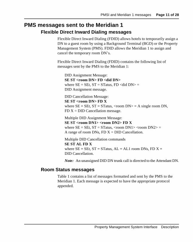
PMS messages sent to the Meridian 1Flexible Direct Inward Dialing messages
Flexible Direct Inward Dialing (FDID) allows hotels to temporarily assignDN to a guest room by using a Background Terminal (BGD) or the PropeManagement System (PMS). FDID allows the Meridian 1 to assign and cancel the temporary room DN’s.
Flexible Direct Inward Dialing (FDID) contains the following list of messages sent by the PMS to the Meridian 1:
DID Assignment Message:SE ST <room DN> FD <did DN>where SE = SEt, ST = STatus, FD <did DN> = DID Assignment message.
DID Cancellation Message:SE ST <room DN> FD X where SE = SEt, ST = STatus, <room DN> = A single room DN,FD X = DID Cancellation message.
Multiple DID Assignment Message:SE ST <room DN1> <room DN2> FD Xwhere SE = SEt, ST = STatus, <room DN1> <room DN2> = A range of room DNs, FD X = DID Cancellation.
Multiple DID Cancellation commandsSE ST AL FD Xwhere SE = SEt, ST = STatus, AL = AL1 room DNs, FD X = DID Cancellation.
Note: An unassigned DID DN trunk call is directed to the Attendant D
Room Status messagesTable 1 contains a list of messages formatted and sent by the PMS to thMeridian 1. Each message is expected to have the appropriate protocol appended.
Property Management System Interface Description
Page 12 of 28 PMSI and Meridian 1 messages
dds
, aid
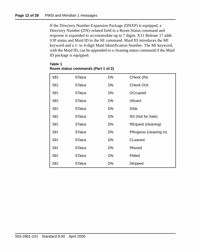
If the Directory Number Expansion Package (DNXP) is equipped, a Directory Number (DN)–related field in a Room Status command and response is expanded to accommodate up to 7 digits. X11 Release 17 aVIP status and Maid ID to the SE command. Maid ID introduces the MI keyword and a 1- to 4-digit Maid Identification Number. The MI keywordwith the Maid ID, can be appended to a cleaning status command if the MID package is equipped.
Table 1Room status commands (Part 1 of 2)
SEt STatus DN CHeck (IN)
SEt STatus DN CHeck OUt
SEt STatus DN OCcupied
SEt STatus DN VAcant
SEt STatus DN SAle
SEt STatus DN NS (Not for Sale)
SEt STatus DN REquest (cleaning)
SEt STatus DN PRogress (cleaning in)
SEt STatus DN CLeaned
SEt STatus DN PAssed
SEt STatus DN FAiled
SEt STatus DN SKipped
553-2801-101 Standard 9.00 April 2000
PMSI and Meridian 1 messages Page 13 of 28
port. as if
and e eses
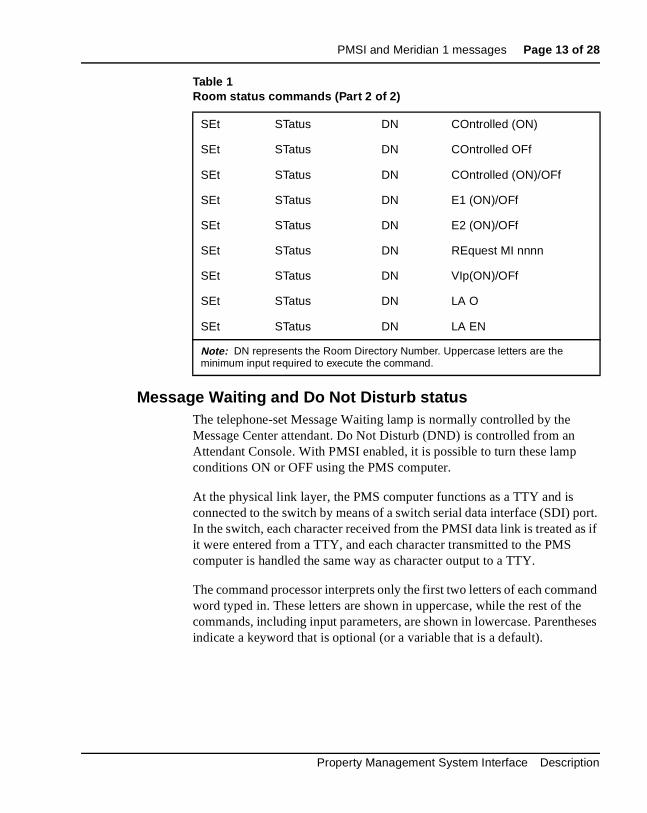
Message Waiting and Do Not Disturb statusThe telephone-set Message Waiting lamp is normally controlled by the Message Center attendant. Do Not Disturb (DND) is controlled from an Attendant Console. With PMSI enabled, it is possible to turn these lampconditions ON or OFF using the PMS computer.
At the physical link layer, the PMS computer functions as a TTY and is connected to the switch by means of a switch serial data interface (SDI) In the switch, each character received from the PMSI data link is treated it were entered from a TTY, and each character transmitted to the PMS computer is handled the same way as character output to a TTY.
The command processor interprets only the first two letters of each commword typed in. These letters are shown in uppercase, while the rest of thcommands, including input parameters, are shown in lowercase. Parenthindicate a keyword that is optional (or a variable that is a default).
SEt STatus DN COntrolled (ON)
SEt STatus DN COntrolled OFf
SEt STatus DN COntrolled (ON)/OFf
SEt STatus DN E1 (ON)/OFf
SEt STatus DN E2 (ON)/OFf
SEt STatus DN REquest MI nnnn
SEt STatus DN VIp(ON)/OFf
SEt STatus DN LA O
SEt STatus DN LA EN
Note: DN represents the Room Directory Number. Uppercase letters are the minimum input required to execute the command.
Table 1Room status commands (Part 2 of 2)
Property Management System Interface Description

Page 14 of 28 PMSI and Meridian 1 messages
tocol
MS
us of ng
The exact commands listed here are expected to have the appropriate proappended.
Message Waiting:SEt STatus DN MW (ON)SEt STatus DN MW OFf
Do Not Disturb:SEt STatus DN DNd (ON)SEt STatus DN DNd OFf
For PMSI, all new and existing commands are supported as of X11 Release 17. In addition, the new parameter (X11 Release 16 software), LAnguage, added to the OPtion, STatus, and CPnd commands, are alsorecognized by the PMSI.
Note: Only single Room Status commands should be sent from the Pto the Meridian 1.
Automatic controlThe PMS can request the system to automatically change the room statall occupied rooms to “REquested” every day at a specific time by sendithe following message where “hour1” is the time in 24-hour format:
SEt OPtion TIme REquested hour1
To cancel the automatic status change, the following message is sent:
SEt OPtion TIme REquest OFf
553-2801-101 Standard 9.00 April 2000
PMSI and Meridian 1 messages Page 15 of 28
one d and ed,
the
e
d
Off Hook DetectionThe PMS can specify a time when the cleaning staff can use the room phto signal that the room has been cleaned. The room phone handset is lifteleft off hook to signal “cleaning in PRogress.” When the handset is replaccleaning status is updated to “CLeaned.”
X11 Release 17 introduces Maid Identification. Off Hook Detection sendsdefault Maid ID number of zero (o) to the PMS if the Maid ID package isequipped. See X11 Features and Services (553-3001-306).
The option is set using the following command, where “t1” is the start timfor the Off Hook Detection plan, and “t2” is the end time for the Off HookDetection plan:
SEt OPtion TIme DEtect t1 t2
Note: End time (t2) must be greater than the start time (t1). If the entime is not entered, t2 defaults to midnight, 2400.
Property Management System Interface Description
Page 16 of 28 PMSI and Meridian 1 messages
hod . To
e PRE
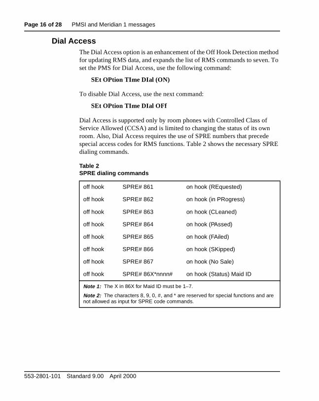
Dial AccessThe Dial Access option is an enhancement of the Off Hook Detection metfor updating RMS data, and expands the list of RMS commands to sevenset the PMS for Dial Access, use the following command:
SEt OPtion TIme DIal (ON)
To disable Dial Access, use the next command:
SEt OPtion TIme DIal OFf
Dial Access is supported only by room phones with Controlled Class of Service Allowed (CCSA) and is limited to changing the status of its own room. Also, Dial Access requires the use of SPRE numbers that precedspecial access codes for RMS functions. Table 2 shows the necessary Sdialing commands.
Table 2SPRE dialing commands
off hook SPRE# 861 on hook (REquested)
off hook SPRE# 862 on hook (in PRogress)
off hook SPRE# 863 on hook (CLeaned)
off hook SPRE# 864 on hook (PAssed)
off hook SPRE# 865 on hook (FAiled)
off hook SPRE# 866 on hook (SKipped)
off hook SPRE# 867 on hook (No Sale)
off hook SPRE# 86X*nnnn# on hook (Status) Maid ID
Note 1: The X in 86X for Maid ID must be 1–7.
Note 2: The characters 8, 9, 0, #, and * are reserved for special functions and are not allowed as input for SPRE code commands.
553-2801-101 Standard 9.00 April 2000
PMSI and Meridian 1 messages Page 17 of 28
e”
D
d of is
Call Party Name Display name changeThe PMS computer can change a Call Party Name Display (CPND) “namassociated with a given DN. To execute the change, use the following commands:
SEt CPnd dn "guest name" xpln LAnguage # room status
The CPND name must be enclosed in double quotes and cannot contain an asterisk (*), colon (:), or carriage return (<CR>). You must define the CPNdata block in LD 95 before implementing the SEt CPnd command.
The first SEt CPND command defines the CPND name and the expectelength. If the XPLN field is not specified, then it defaults to the actual sizethe name string or the default length (DFLN) defined in LD 95, whicheverlarger.
Refer to X11 Features and Services (553-3001-306) to configure and enable CPND.
Legenddn = station set DN
"guest name" = CPND name for the DN
xpln = Expected Name Length
# = language assignment for the room
room status = RMS coded indicator (checked in or out)
Property Management System Interface Description
Page 18 of 28 PMSI and Meridian 1 messages
ber ll a
nd
e
,
th
e
et
Call Number Information messagesWith X11 Release 12 and later, if the terminating telephone has Call NumInformation Allowed (CNIA) class of service (CLS), the system sends CaInitiation and Call Disconnection messages for calling and called DNs onreal-time basis to the Background Terminal (BGD) and PMSI ports.
Class of service for CNIA is limited to 60 sets and is assigned in LD 10 aLD 11. Refer to Nortel Networks technical publication X11 Features and Services (553-3001-306) and X11 Administration (553-3001-311).
Note: A set that is assigned Virtual ACD Agent (VMA) class of serviccannot be assigned CNIA class of service.
Message formats sent to the BGD port and PMSI ports are shown belowwhere “XXXX” is the calling DN, and “YYYY” is the called DN:
ST-CI XXXX YYYY
ST-CT XXXX YYYY
Note: The calling or called DN can have up to 7 digits if equipped withe DNXP package.
When equipped with the DNXP package, the Originating DN and Terminating DN fields in Call Initiated and Call Terminated messages arexpanded from 6 bytes to 7 bytes.
Call Initiated (CI) A Call Initiated message is sent when the terminating shas Call Number Information Allowed (CNIA) class of service (CLS) andone of the following conditions occurs:
— The telephone set goes off hook and a number is dialed.
— The call is reestablished from On-Hold status.
— The telephone set is the third party in a Call Transfer.
— The set terminates a Forwarded Call.
— The call is picked up by a station.
— The Call Waiting key on a CNIA set is pressed.
— The call is extended by an attendant.
553-2801-101 Standard 9.00 April 2000
PMSI and Meridian 1 messages Page 19 of 28
Call Terminated (CT) A Call Terminated message is sent when the terminating set has Call Number Information Allowed (CNIA) class of service (CLS) and one of the following conditions occurs:
— Call termination to a non-CNIA set
— Call Forward No Answer (CFNA)
— Call Park
— Call Transfer from originating or terminating sets
— Call Pickup received by the set
— Conference call
— Call On Hold
No messages are sent for the following call types:
— Dial Intercom calls
— overridden calls
— attendant calls
— CNIA-originated calls
— Automatic Wake Up calls
— trunk calls
Property Management System Interface Description
Page 20 of 28 PMSI and Meridian 1 messages
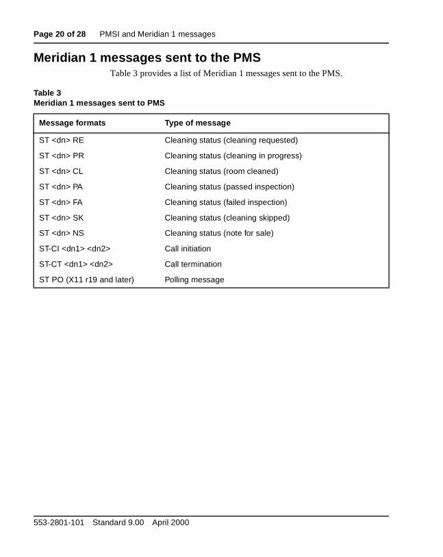
Meridian 1 messages sent to the PMSTable 3 provides a list of Meridian 1 messages sent to the PMS.
Table 3Meridian 1 messages sent to PMS
Message formats Type of message
ST <dn> RE Cleaning status (cleaning requested)
ST <dn> PR Cleaning status (cleaning in progress)
ST <dn> CL Cleaning status (room cleaned)
ST <dn> PA Cleaning status (passed inspection)
ST <dn> FA Cleaning status (failed inspection)
ST <dn> SK Cleaning status (cleaning skipped)
ST <dn> NS Cleaning status (note for sale)
ST-CI <dn1> <dn2> Call initiation
ST-CT <dn1> <dn2> Call termination
ST PO (X11 r19 and later) Polling message
553-2801-101 Standard 9.00 April 2000
Page 21 of 28
26
is
a d is
iver
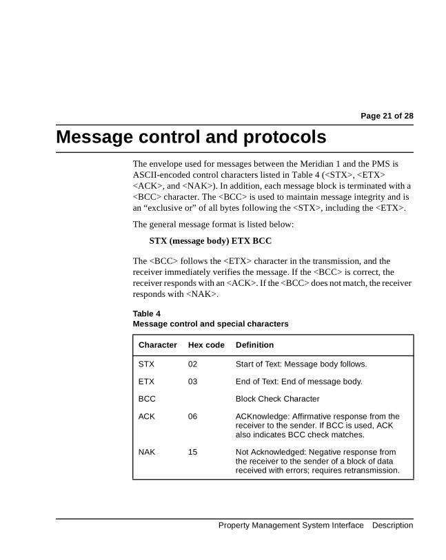
Message control and protocolsThe envelope used for messages between the Meridian 1 and the PMS ASCII-encoded control characters listed in Table 4 (<STX>, <ETX> <ACK>, and <NAK>). In addition, each message block is terminated with<BCC> character. The <BCC> is used to maintain message integrity anan “exclusive or” of all bytes following the <STX>, including the <ETX>.
The general message format is listed below:
STX (message body) ETX BCC
The <BCC> follows the <ETX> character in the transmission, and the receiver immediately verifies the message. If the <BCC> is correct, the receiver responds with an <ACK>. If the <BCC> does not match, the receresponds with <NAK>.
Table 4Message control and special characters
Character Hex code Definition
STX 02 Start of Text: Message body follows.
ETX 03 End of Text: End of message body.
BCC Block Check Character
ACK 06 ACKnowledge: Affirmative response from the receiver to the sender. If BCC is used, ACK also indicates BCC check matches.
NAK 15 Not Acknowledged: Negative response from the receiver to the sender of a block of data received with errors; requires retransmission.
Property Management System Interface Description
Page 22 of 28 Message control and protocols
the
smit
e to S ian
he
age e
the
the ill
e
Message protocolsSoftware protocols have been implemented to supply a method of flow control across the data link. The PMS computer is given priority, and theresponsibilities of the system and the PMS have been defined.
Meridian 1 protocolThe following sections list the transmitting and receiving requirements for Meridian 1 protocol:
Transmitting requirements
— The Meridian 1 must calculate a <BCC> for each message, and tranit as a terminating character.
— Prior to X11 Release 19, when the Meridian 1 transmitted a messagthe PMS, it would ignore any <ACK> or <NAK> received from the PMand would not attempt to retransmit the message. Instead, the Merid1 could transmit a new message to the PMS immediately following tprevious message, without any gap in transmission.
With X11 Release 19 and later, when the Meridian 1 transmits a messto the PMS, it no longer ignores an <ACK> or <NAK> received from thPMS, but waits for a specified interval (defined on a system basis) forPMS to respond before sending the next message.
Receiving requirements
— When the Meridian 1 receives a message from the PMS, a <BCC> forreceived characters following the <STX> and including the <ETX> wbe calculated and compared with the received <BCC>. If the BCCs match, an <ACK> is sent to the PMS. If the BCCs do not match, a <NAK> is sent to the PMS.
The <ACK> or <NAK>, sent back to the PMS, will follow any messagthat is currently being transmitted by the Meridian 1, such as a roomcleaning status message.
553-2801-101 Standard 9.00 April 2000
Message control and protocols Page 23 of 28
as a
if
to me.
imer
age
e.
e age.
PMS protocolThe PMS can operate using three slightly different protocols:
— PMS1The first PMS protocol is the standard interface and default value.
— Format 2 (Format B)The second protocol allowed requires a carriage return (<CR>) to recognize the input message.
— Format 3 (Format C)The third protocol allows for any updated RMS message sent to be followed by the old room status whenever a room DN checks in or checks out.
Within all three types, it is recommended that the PMS adhere to the following protocol requirements:
Transmitting requirements
— The PMS must calculate a <BCC> for each message and transmit itterminating character.
All messages transmitted by the PMS should be “single room” commands. The PMS may run into timing and flow-control problemsyou use “multiple” room commands.
— After transmitting a message, the PMS must wait for the Meridian 1 acknowledge receipt of the message within a predefined period of ti
The recommended period of time for the message acknowledgment tis 2 seconds.
If the PMS receives an <ACK> from the Meridian 1 before the acknowledgment timer expires, the PMS can transmit the next messimmediately. That is, the PMS does not have to wait for the acknowledgment timer to expire before transmitting the next messag
If the PMS receives a <NAK> from the Meridian 1 before the acknowledgment timer expires, the PMS can retransmit the same message immediately. That is, the PMS does not have to wait for thacknowledgment timer to expire before retransmitting the next mess
Property Management System Interface Description
Page 24 of 28 Message control and protocols
the
he em,
age.
ld
until
MS uired hould
ich
ate
ge
ers in mit a the
MS as
After three retransmission attempts, however, the PMS should take following actions:
• Flag the problem to hotel personnel so that the usual corrective action can be taken.
Note: The usual corrective action for most problems would involve tdetermination of the exact cause of failure, the correction of the probland a database swap to resynchronize the system.
• Store the message in an error file, and then send the next mess
— If the PMS does not receive an <ACK> or <NAK> from the Meridian 1 before the acknowledgment timer expires, the PMS shouassume that the message was lost and should retransmit the same message. The PMS should continue to retransmit the same messagethe Meridian 1 acknowledges receipt of that message.
The PMS should queue all other messages for the Meridian 1. If the Pqueue fills up, messages may be lost and a database swap will be reqto recover the lost messages. If PMSI messages are lost, the PMS sflag the problem for the hotel personnel.
Note: Some vendors using the PMS protocol may want to follow anearlier strategy of allowing only three transmission attempts, after whthe message is stored in a PMS error file and the next message is transmitted. The new strategy described above is designed to facilitrecovery from short-link outages.
— The PMS should send an <ACK> or <NAK> upon receiving a messafrom the Meridian 1.
Prior to X11 Release 19, it was not necessary to send these charactresponse to PMSI messages, because the Meridian 1 did not retrans<NAK> message and did not wait for a response before transmittingnext message.
With X11 Release 19 and later, it is strongly recommended that the Psend <ACK> and <NAK> responses, because the Meridian 1 now hthe capability to retransmit messages.
553-2801-101 Standard 9.00 April 2000
Message control and protocols Page 25 of 28
he
ding sage
d
or”.
In addition to message retransmission, X11 Release 19 introduces apolling functionality to test the status of the PMSI link. The polling message may not be recognized by the PMS. However, it is stronglyrecommended that the PMS treat the polling message as a standardMeridian 1 message by responding with an <ACK> upon receiving tmessage in its correct form.
Note: It is required that <ACK> and <NAK> characters be sent onlybetween message packets. That is, if the PMS is in the middle of sena message to the Meridian 1, it must finish sending the complete mesbefore sending an <ACK> or <NAK> back to the Meridian 1.
Receiving requirements
— When the PMS receives a message from the Meridian 1, it is recommended that the <BCC> of the messages received be checkeinternally by the PMS and an <ACK> or <NAK> be sent back to the Meridian 1.
— It is recommended that any error detected be stored in an error file.
Note: The PMS must not send any error response to the Meridian 1about a received message, such as “Invalid command” or “Syntax err
Property Management System Interface Description
Page 26 of 28 Message control and protocols
553-2801-101 Standard 9.00 April 2000
Page 27 of 28
28
Index
Aautomatic room status changes, 14BBGD (Background Terminal)
described, 8
CCall Initiated messages, 18Call Number Information Messages (CNIM), 18Call Party Name Display (CPND), 17Call Terminated messages (CT), 19CCSA (Controlled Class of Service Allowed), 16CI (Call Initiated) messages, 18cleaning status, 15commands
issuing database updates, 7MMS filtering, 8Room Status, 12single room vs. multiple room, 23SPRE, 16syntax, 13
Controlled Class of Service Allowed (CCSA), 16CPND (Call Party Name Display), 17CT (Call Terminated) messages, 19
DDial Access option
described, 16DN name changes, 17DND (Do Not Disturb) status message, 13
DNXP (Directory Number Expansion Package)Call Initiated/Call Terminated messages, 18Room Status DN command, 12
Do Not Disturb (DND) status message, 13Do Not Disturb command, 14
Eerror responses, 25
MMaid ID, 12Meridian 1
BGD connection, 8retransmitting messages, 24
Meridian 1 database, 7Meridian 1 message protocol, 22Meridian 1 messages, 9, 20Meridian Hospitality Voice Services (MHVS), 8Meridian Mail Server (MMS), 8message retransmission
after <NAK> response from Meridian 1, 23no <ACK>/<NAK> response from Meridian 1,
24Message Waiting command, 14Message Waiting lamp, 13messages
control characters, 21protocols, 22types of, 9
MHVS (Meridian Hospitality Voice Services), 8MI keyword, 12MMS (Meridian Mail Server), 8
Property Management System Interface Description
Page 28 of 28
OOff Hook Detection, 15
PPMS (Property Management System), 7PMS database, 7PMS message protocols, 23PMS messages, 9, 11PMSI (Property Management System Interface)
feature description, 7MHVS use of, 8TTY emulation, 13
polling, 25Property Management System, 7protocols, message, 22
Rreceiving requirements
Meridian 1 message protocol, 22PMS message protocol, 25
retransmitting messages, 23, 24RMS (Room Status) messages
automatic changes to, 14described, 11
SSDI (serial data interface) port
BGD to Meridian 1 connection, 8SPRE numbers/commands, 16
Ttransmitting requirements
Meridian 1 message protocol, 22PMS protocol, 23
Uupdating databases, 7
VVIP status, 12VMA (Virtual ACD Agent), 18
XX11 release 12, 18X11 release 17
SE command additions, 12X11 release 19
<ACK>/<NAK> Meridian 1 message responses, 24
Meridian 1 protocols, 22polling, 25
553-2801-101 Standard 9.00 April 2000

Family Product Manual Contacts Copyright FCC notice Trademarks Document number Product release Document release Date Publish
Meridian 1
Property Management System InterfaceDescription
Copyright ©1989–2000 Nortel NettworksAll Rights ReservedInformation is subject to change without notice. Nortel Networks reserves the right to make changes in design or components as progress in engineering and manufacturing may warrant. This equipment has been tested and found to comply with the limits for a Class A digital device pursuant to Part 15 of the FCC rules, and the radio interference regulations of Industry Canada. These limits are designed to provide reasonable protection against harmful interference when the equipment is operated in a commercial environment. This equipment generates, uses and can radiate radio frequency energy, and if not installed and used in accordance with the instruction manual, may cause harmful interference to radio communications. Operation of this equipment in a residential area is likely to cause harmful interference in which case the user will be required to correct the interference at their own expense.SL-1 and Meridian 1 are trademarks of Nortel Networks.Publication number: 553-2801-101Document release: Standard 9.00Date: April 2000Printed in Canada


![[MS-WOPI]: Web Application Open Platform Interface Protocol... · [MS-WOPI]: Web Application Open Platform Interface Protocol Intellectual Property Rights Notice for Open Specifications](https://img.pdfslide.us/doc/110x75/603bbb52dcc63828e230e64a/ms-wopi-web-application-open-platform-interface-protocol-ms-wopi-web.jpg)