Embed Size (px)
Citation preview
Meridian 1
Option 11C1.5 Mb DTI/PRI
Document Number: 553-3011-310Document Release: Standard 13.00Date: January 2002
Year Publish FCC TM
Copyright © 1992–2002 Nortel NetworksAll Rights Reserved
Printed in Canada
Information is subject to change without notice. Nortel Networks reserves the right to make changes in designor components as progress in engineering and manufacturing may warrant. This equipment has been testedand found to comply with the limits for a Class A digital device pursuant to Part 15 of the FCC rules, and theradio interference regulations of Industry Canada. These limits are designed to provide reasonable protectionagainst harmful interference when the equipment is operated in a commercial environment. This equipmentgenerates, uses and can radiate radio frequency energy, and if not installed and used in accordance with theinstruction manual, may cause harmful interference to radio communications. Operation of this equipment in aresidential area is likely to cause harmful interference in which case the user will be required to correct theinterference at their own expense.
SL-1 and Meridian 1 are trademarks of Nortel Networks.

Page 3 of 100
Revision historyJanuary 2002
Standard 13.00. This global document is up-issued for Release 25.40.
December 2000 Standard 12.00. This global document is up-issued to include updates andchanges required for Option 11C IP Expansion field trials with Release 25.3xsoftware.
April 2000Standard 11.00. This is a global document and is up-issued for X11 Release25.0x. Document changes include removal of: redundant content; referencesto equipment types except Options 11C, 51C, 61C, and 81C; and referencesto previous software releases.
May 1999Issue 10.00, Standard, published for Generic X11 Release 24.0x.
October 1997Issue 9.00, Standard, published for Generic X11 Release 23.0x.
September 1996Issue 8.00, Standard, published for Generic X11 Release 22.0x.
November 1995Issue 7.00, Standard, published for Generic X11 Release 21.1x
July 1995Issue 6.00, Standard, published for Generic X11 Release 21.0x
December 1994Issue 5.00, Standard, published for Generic X11 Release 20.0x.
Option 11C 1.5 Mb DTI/PRI
Page 4 of 100 Revision History
July 1994Issue 4.00, Standard, published for Generic X11 Release 19.0x.
February 1994Issue 3.00, Standard, published for Generic X11 Release 18.0x.
January 1993Issue 2.00, Standard, published for Generic X11 Release 17.0x.
April 1992Issue 1.00, Standard, published for Generic X11 Release 16.0x.
553-3011-310 Standard 13.00 January 2002
Page 5 of 100
6
Contents
About this guide . . . . . . . . . . . . . . . . . . . . . . . . . . . 7
PRI Implementation . . . . . . . . . . . . . . . . . . . . . . . . . 9
DTI Implementation . . . . . . . . . . . . . . . . . . . . . . . . . 37
DTI/PRI Maintenance . . . . . . . . . . . . . . . . . . . . . . . . 47
ISL Implementation . . . . . . . . . . . . . . . . . . . . . . . . . 79
ISL Maintenance . . . . . . . . . . . . . . . . . . . . . . . . . . . 93
Option 11C 1.5 Mb DTI/PRI

Page 6 of 100 Contents
553-3011-310 Standard 13.00 January 2002
Page 7 of 100
8
About this guideThis document contains specific information on how to configure ISDN DTI/PRI on Meridian 1 Option 11C systems. For general information, and for information on software features, refer to Networking Features and Services (553-2901-301).
This document is a global document. Contact your system supplier or your Nortel Networks representative to verify that the hardware and software described is supported in your area.
Option 11C 1.5 Mb DTI/PRI
Page 8 of 100 About this guide
553-3011-310 Standard 13.00 January 2002
Page 9 of 100
36
PRI ImplementationContents
This section contains information on the following topics:
Reference list . . . . . . . . . . . . . . . . . . . . . . . . . . . . . . . . . . . . . . . . . . . . . 10
Overview . . . . . . . . . . . . . . . . . . . . . . . . . . . . . . . . . . . . . . . . . . . . . . . . 10
Hardware Requirements . . . . . . . . . . . . . . . . . . . . . . . . . . . . . . . . . . . . . 11
Circuit cards . . . . . . . . . . . . . . . . . . . . . . . . . . . . . . . . . . . . . . . . . . . . . . 11
Cables . . . . . . . . . . . . . . . . . . . . . . . . . . . . . . . . . . . . . . . . . . . . . . . . . . . 11
Channel Service Units . . . . . . . . . . . . . . . . . . . . . . . . . . . . . . . . . . . . . . 11
Hardware description . . . . . . . . . . . . . . . . . . . . . . . . . . . . . . . . . . . . . . . 12
NTRB21 TMDI card . . . . . . . . . . . . . . . . . . . . . . . . . . . . . . . . . . . . . . . 12
NTAK09 DTI/PRI circuit card . .. . . . . . . . . . . . . . . . . . . . . . . . . . . . . . 14
NTAK20 Clock Controller (CC) daughterboard . . . . . . . . . . . . . . . . . . 15
Shelf slot assignment . . . . . . . . . . . . . . . . . . . . . . . . . . . . . . . . . . . . . . . 15
Clocking modes . . . . . . . . . . . . . . . . . . . . . . . . . . . . . . . . . . . . . . . . . . . 15
Clock controller LED states . . . . . . . . . . . . . . . . . . . . . . . . . . . . . . . . . . 17
NTAK93 D-channel Handler Interface (DCHI) daughterboard . . . . . . 17
NTBK51BA Downloadable D-channel daughterboard . . . . . . . . . . . . . 18
Install PRI hardware . .. . . . . . . . . . . . . . . . . . . . . . . . . . . . . . . . . . . . . . 18
Insert/remove the NTRB21 TMDI card . . . . . . . . . . . . . . . . . . . . . . . . . 18
Mount the NTAK20 daughterboard on the NTRB21 . .. . . . . . . . . . . . . 20
Mount the NTAK93 or NTBK51 daughterboard on the NTAK09 . . . . 21
Remove the daughterboards from the NTAK09 . . . . . . . . . . . . . . . . . . 24
Option 11C 1.5 Mb DTI/PRI
Page 10 of 100 PRI Implementation
Set the switches . . . . . . . . . . . . . . . . . . . . . . . . . . . . . . . . . . . . . . . . . . . . 24
Insert the NTAK09 into the main cabinet . . . . . . . . . . . . . . . . . . . . . . . . 25
Connect the cables . . . . . . . . . . . . . . . . . . . . . . . . . . . . . . . . . . . . . . . . . . 25
Install IP daughterboards . . . . . . . . . . . . . . . . . . . . . . . . . . . . . . . . . . . . . 26
Software enable the DTI/PRI cards . . . . . . . . . . . . . . . . . . . . . . . . . . . . . 26
Software enable the NTRB21 TMDI card . . . . . . . . . . . . . . . . . . . . . . . . 26
Software enable the NTAK09 card . . . . . . . . . . . . . . . . . . . . . . . . . . . . . 26
Program Basic PRI . .. . . . . . . . . . . . . . . . . . . . . . . . . . . . . . . . . . . . . . . . 27
Prerequisites . . . . . . . . . . . . . . . . . . . . . . . . . . . . . . . . . . . . . . . . . . . . . . . 27
Program procedure . .. . . . . . . . . . . . . . . . . . . . . . . . . . . . . . . . . . . . . . . . 28
Reference listThe following are the references in this section:
• Networking Features and Services (553-2901-301)
• Administration (553-3001-311)
• Option 11C and 11C Mini Technical Reference Guide (553-3011-100)
• Option 11C Planning and Installation (553-3021-210)
OverviewDigital trunks are now supported in both Main Option 11C cabinets and IP Expansion cabinets. This increased capability is possible with the introduction of IP daughterboards in expansion cabinets and 100baseT or F connectivity with the Main cabinet.
This chapter provides the information required to install PRI on a Meridian 1 Option 11C system:
• hardware and software installation
• programming procedures for basic call service.
While either the hardware or software may be installed first, the PRI cannot be enabled and tested until both are completed.
553-3011-310 Standard 13.00 January 2002
PRI Implementation Page 11 of 100
Hardware RequirementsCircuit cards
To implement PRI on the Meridian 1 Option 11C, the hardware shown in Table 1 on page 11 is required.
CablesThe following cables are required for PRI connections:
• PRI to external T1 cable
• NTBK04 carrier cable
• NT8D97 50 foot extension (if needed)
Channel Service UnitsWhen connecting the DTI/PRI to the public network, CSUs are required by most operating companies. One CSU is required per PRI. Suitable CSUs which support 64 Kbps clear and Bipolar 8 Zero Substitution (B8ZS) are available from vendors such as Verilink, Digitalink, Kentrox and Tellabs.
Table 1Required Circuit Cards
Circuit card Description
NTRB21 DTI/PRI TMDI card.
NTAK09 DTI/PRI circuit card.
NTAK20 Clock-controller daughterboard. Option 11C supports only one active clock controller per system or IP Expansion cabinet.
Note: Every cabinet that contains a digital trunk must contain a clock controller.
NTAK93 D-channel-handler interface (DCH) daughterboard.
NTBK51BA Downloadable D-channel daughterboard (DDCH). Connects to the NTAK09 DTI/PRI card.
Option 11C 1.5 Mb DTI/PRI
Page 12 of 100 PRI Implementation
Note: Contact your Nortel Networks Sales representative for specific local CSU requirements.
Hardware descriptionNTRB21 TMDI card
The NTRB21 TMDI card provides 1.5 MBit/s Digital Trunk Interface or Primary Rate Interface functionality on the Option 11C. The NTRB21 has a built-in downloadable D-channel which may occupy any single card slot (1-9), in the Option 11C main cabinet. In IP Expansion cabinets, the card may be placed in slots 11-19, 21-29, 31-39 or 41-49 of the first, second, third and fourth expansion cabinets, respectively.
Note 1: For CISPR B group cabinets, the active Clock Controller (NTAK20) can only occupy slots 1-3, 11-13, 21-23, 31-33, or 41-43 in an Option 11C cabinet. For FCC and/or CISPR A group cabinets, this limitation does not exist.
Note 2: The NTRB21can be equipped together with the NTAK09 DTI/PRI card (with the NTBK51 downloadable D-channel daughterboard), and the NTAK93 DCHI daughterboard.
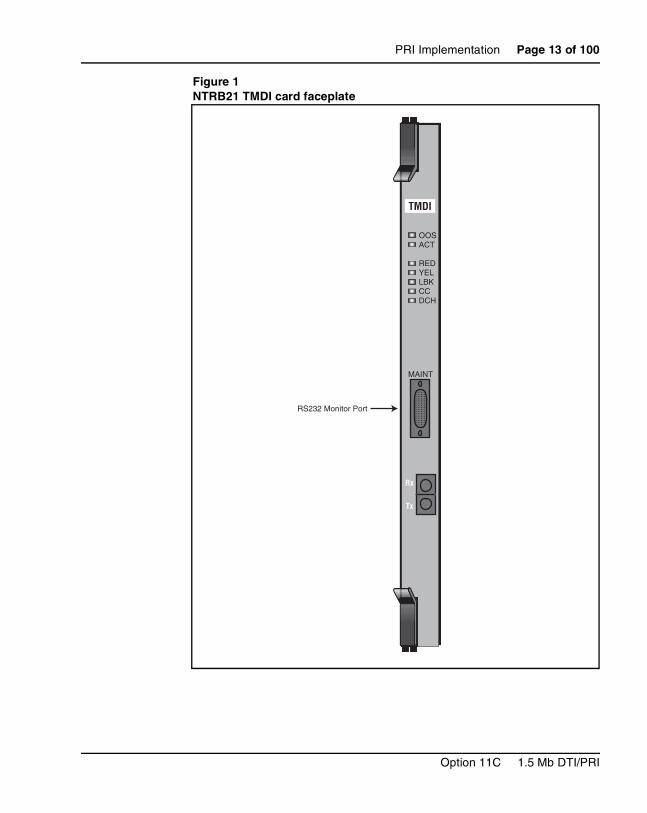
Figure 1 on page 13 shows a faceplate of the NTRB21 TMDI card.
553-3011-310 Standard 13.00 January 2002
PRI Implementation Page 13 of 100
Figure 1NTRB21 TMDI card faceplate
TMDI
Rx
Tx
OOSACT
REDYELLBKCCDCH
................................................................
MAINT
RS232 Monitor Port
Option 11C 1.5 Mb DTI/PRI
Page 14 of 100 PRI Implementation
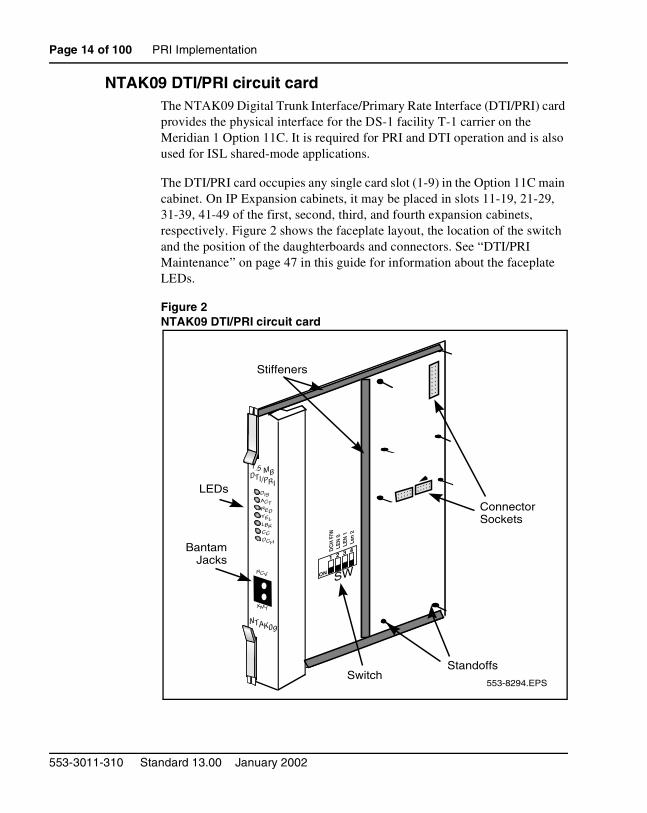
NTAK09 DTI/PRI circuit card The NTAK09 Digital Trunk Interface/Primary Rate Interface (DTI/PRI) card provides the physical interface for the DS-1 facility T-1 carrier on the Meridian 1 Option 11C. It is required for PRI and DTI operation and is also used for ISL shared-mode applications.
The DTI/PRI card occupies any single card slot (1-9) in the Option 11C main cabinet. On IP Expansion cabinets, it may be placed in slots 11-19, 21-29, 31-39, 41-49 of the first, second, third, and fourth expansion cabinets, respectively. Figure 2 shows the faceplate layout, the location of the switch and the position of the daughterboards and connectors. See “DTI/PRI Maintenance” on page 47 in this guide for information about the faceplate LEDs.
Figure 2NTAK09 DTI/PRI circuit card
DISACTREDYELLBKCCDCH
RCV
XMT
NTAK09
1.5 MBDTI/PRI
ON
1 2 3 4DC
H F
/WLE
N 0
LEN
1Le
n 2
SWON
1 2 3 4
DC
H F
/WLE
N 0
LEN
1Le
n 2
553-8294.EPS
SW
Stiffeners
ConnectorSockets
LEDs
BantamJacks
StandoffsSwitch
553-3011-310 Standard 13.00 January 2002
PRI Implementation Page 15 of 100
NTAK20 Clock Controller (CC) daughterboard Digital Trunking requires synchronized clocking so that a shift in one clock source will result in an equivalent shift of the same size and direction in all parts of the network. On Option 11C systems, synchronization is accomplished with the NTAK20 clock controller circuit card in each Main and IP Expansion cabinet.
The Clock Controller circuitry synchronizes the Option 11C to an external reference clock, and generates and distributes the clock to the system. Option 11C can function either as a slave to an external clock or as a clocking master. The NTAK20AA version of the clock controller meets AT&T Stratum 3 and Bell Canada Node Category D specifications. The NTAK20BA version meets CCITT stratum 4 specifications.
Shelf slot assignmentOn non-CISPR B system cabinets, the NTAK20 may be placed in slots 1-9 of the Main cabinet. On cabinets NTAK11Dx and NTAK11Fx, the active NTAK20 must be placed in slots 1-3 (slots 4-10 may not be used.)
On non-CISPR B IP Expansion cabinets, the NTAK20 may be placed in slots 11-19, 21-29, 31-39, 41-49 of the first, second, third, and fourth expansion cabinets, respectively.
Clocking modesThe Option 11C system supports a single clock controller that can operate in one of two modes: tracking or non-tracking (also known as free-run).
IMPORTANT
Every cabinet that contains a digital trunk must contain a clock controller. If a system is equipped with digital trunks, it is recommended that at least one digital trunk be placed in the main cabinet. If there is a mixture of TMDI and non-TMDI in the same cabinet, place the clock controller on the non-TMDI card.
Option 11C 1.5 Mb DTI/PRI

Page 16 of 100 PRI Implementation
Tracking modeIn tracking mode, one or possibly two DTI/PRI cards supply a clock reference to a clock controller daughterboard. When operating in tracking mode, one DTI/PRI is defined as the primary reference source for clock synchronization, while the other is defined as the secondary reference source (PREF and SREF in LD 73).
There are two stages to clock controller tracking:
• tracking a reference, and
• locked onto a reference.
When tracking a reference, the clock controller uses an algorithm to match its frequency to the frequency of the incoming clock. When the frequencies are very near to being matched, the clock controller is locked onto the reference. The clock controller will make small adjustments to its own frequency until both the incoming and system frequencies correspond.
If the incoming clock reference is stable, the internal clock controller will track it, lock onto it, and match frequencies exactly. Occasionally, however, environmental circumstances will cause the external or internal clocks to drift. When this happens, the internal clock controller will briefly enter the tracking stage. The green LED will flash momentarily until the clock controller is locked onto the reference once again.
If the incoming reference is unstable, the internal clock controller will continuously be in the tracking stage, with the LED flashing green all the time. This condition does not present a problem, rather, it shows that the clock controller is continually attempting to lock onto the signal. If slips are occurring, however, it means that there is a problem with the clock controller or the incoming line.
Free-run (non-tracking)In free-run mode, the clock controller does not synchronize on any source, it provides its own internal clock to the system. This mode can be used when the Meridian 1 is used as a master clock source for other systems in the network. Free-run mode is undesirable if the Meridian 1 is intended to be a slave. It can occur, however, when both the primary and secondary clock sources are lost due to hardware faults or when invoked by using software commands.
553-3011-310 Standard 13.00 January 2002
PRI Implementation Page 17 of 100
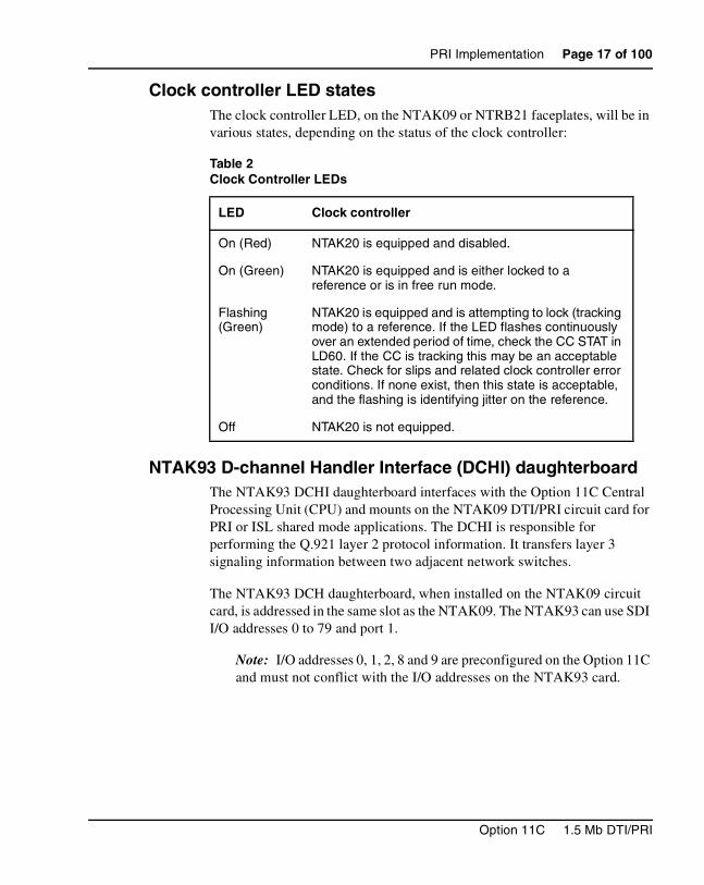
Clock controller LED statesThe clock controller LED, on the NTAK09 or NTRB21 faceplates, will be in various states, depending on the status of the clock controller:
NTAK93 D-channel Handler Interface (DCHI) daughterboard The NTAK93 DCHI daughterboard interfaces with the Option 11C Central Processing Unit (CPU) and mounts on the NTAK09 DTI/PRI circuit card for PRI or ISL shared mode applications. The DCHI is responsible for performing the Q.921 layer 2 protocol information. It transfers layer 3 signaling information between two adjacent network switches.
The NTAK93 DCH daughterboard, when installed on the NTAK09 circuit card, is addressed in the same slot as the NTAK09. The NTAK93 can use SDI I/O addresses 0 to 79 and port 1.
Note: I/O addresses 0, 1, 2, 8 and 9 are preconfigured on the Option 11C and must not conflict with the I/O addresses on the NTAK93 card.
Table 2Clock Controller LEDs
LED Clock controller
On (Red) NTAK20 is equipped and disabled.
On (Green) NTAK20 is equipped and is either locked to a reference or is in free run mode.
Flashing (Green)
NTAK20 is equipped and is attempting to lock (tracking mode) to a reference. If the LED flashes continuously over an extended period of time, check the CC STAT in LD60. If the CC is tracking this may be an acceptable state. Check for slips and related clock controller error conditions. If none exist, then this state is acceptable, and the flashing is identifying jitter on the reference.
Off NTAK20 is not equipped.
Option 11C 1.5 Mb DTI/PRI
Page 18 of 100 PRI Implementation
A minimum of one NTAK93 is required for each PRI link. If more than one PRI link is connected to the same end location, a single DCHI circuit card can support up to a maximum of eight PRI connections for the Option 11C system. This allows a total of 190 B-channels or PRI trunks to be supported if a backup D-channel is also used. A total of 191 B-channels or PRI trunks are supported if a backup channel is not used.
NTBK51BA Downloadable D-channel daughterboardThe NTBK51BA DDCH daughterboard interfaces with the Option 11C Central Processing Unit (CPU) and mounts on the NTAK09 DTI/PRI circuit card for PRI D-channel applications. The DDCH is equivalent to the MSDL card used on the larger Meridian 1 systems, but it only supports D-channel applications (no SDI or ESDI).
The NTBK51BA DDCH daughterboard, when installed on the NTAK09 circuit card, is addressed in the same slot as the NTAK09.
A minimum of one NTBK51BA is required for each PRI link. If more than one PRI link is connected to the same end location, a single DDCH circuit card can support up to a maximum of eight PRI connections for the Option 11C system. This allows a total of 190 B-channels or PRI trunks to be supported if a backup D-channel is also used. A total of 191 B-channels or PRI trunks are supported if a backup channel is not used.
For more information on expansion daughterboards, refer to Option 11C and 11C Mini Technical Reference Guide (553-3011-100).
Install PRI hardwareInsert/remove the NTRB21 TMDI card
Insert the NTRB21Insert the NTRB21 TMDI circuit card into card slot 1-9 in the Main cabinet, or in slots 11-19, 21-29, 31-39, 41-49 of the first, second, third, and fourth Expansion cabinets, respectively. Check for available card slots in the base cabinet and print the configuration record to determine which slots may be used. To do this, use PRT CFN in LD 22. Then, use the following steps:
553-3011-310 Standard 13.00 January 2002
PRI Implementation Page 19 of 100
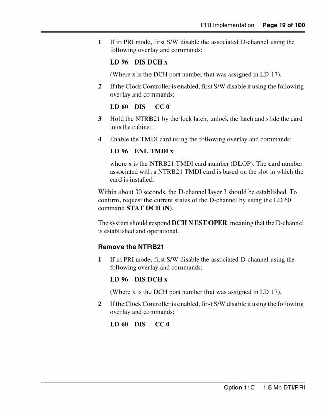
1 If in PRI mode, first S/W disable the associated D-channel using the following overlay and commands:
LD 96 DIS DCH x
(Where x is the DCH port number that was assigned in LD 17).
2 If the Clock Controller is enabled, first S/W disable it using the following overlay and commands:
LD 60 DIS CC 0
3 Hold the NTRB21 by the lock latch, unlock the latch and slide the card into the cabinet.
4 Enable the TMDI card using the following overlay and commands:
LD 96 ENL TMDI x
where x is the NTRB21 TMDI card number (DLOP). The card number associated with a NTRB21 TMDI card is based on the slot in which the card is installed.
Within about 30 seconds, the D-channel layer 3 should be established. To confirm, request the current status of the D-channel by using the LD 60 command STAT DCH (N).
The system should respond DCH N EST OPER, meaning that the D-channel is established and operational.
Remove the NTRB21
1 If in PRI mode, first S/W disable the associated D-channel using the following overlay and commands:
LD 96 DIS DCH x
(Where x is the DCH port number that was assigned in LD 17).
2 If the Clock Controller is enabled, first S/W disable it using the following overlay and commands:
LD 60 DIS CC 0
Option 11C 1.5 Mb DTI/PRI
Page 20 of 100 PRI Implementation
3 Disable the NTRB21 TMDI card using the following overlay and commands:
LD 96 DIS TMDI x
where x is the NTRB21 TMDI card number (DLOP). The card number associated with a NTRB21 TMDI card is based on the slot in which the card is installed.
4 Hold the NTRB21 by the lock latch, unlock the latch and slide the card out from the cabinet.
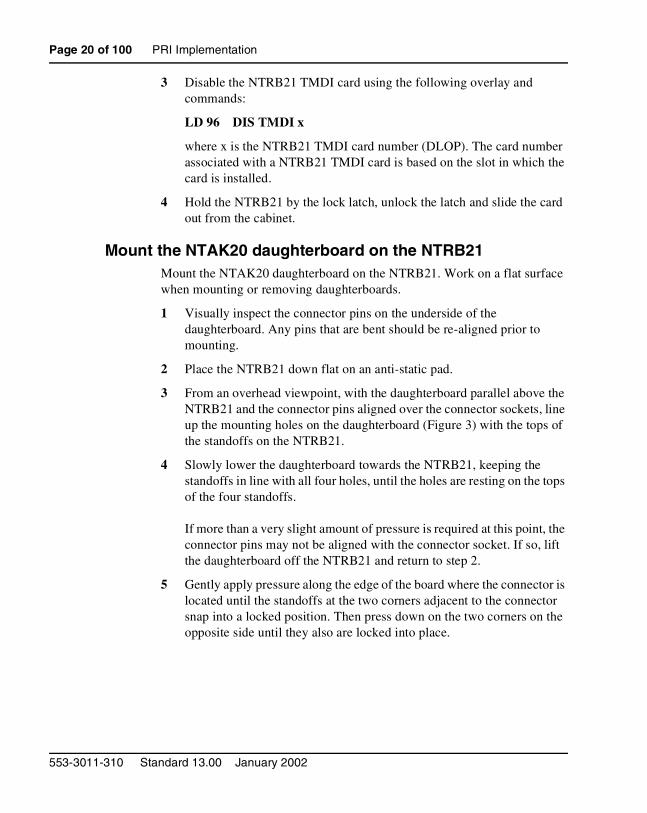
Mount the NTAK20 daughterboard on the NTRB21Mount the NTAK20 daughterboard on the NTRB21. Work on a flat surface when mounting or removing daughterboards.
1 Visually inspect the connector pins on the underside of the daughterboard. Any pins that are bent should be re-aligned prior to mounting.
2 Place the NTRB21 down flat on an anti-static pad.
3 From an overhead viewpoint, with the daughterboard parallel above the NTRB21 and the connector pins aligned over the connector sockets, line up the mounting holes on the daughterboard (Figure 3) with the tops of the standoffs on the NTRB21.
4 Slowly lower the daughterboard towards the NTRB21, keeping the standoffs in line with all four holes, until the holes are resting on the tops of the four standoffs.
If more than a very slight amount of pressure is required at this point, the connector pins may not be aligned with the connector socket. If so, lift the daughterboard off the NTRB21 and return to step 2.
5 Gently apply pressure along the edge of the board where the connector is located until the standoffs at the two corners adjacent to the connector snap into a locked position. Then press down on the two corners on the opposite side until they also are locked into place.
553-3011-310 Standard 13.00 January 2002
PRI Implementation Page 21 of 100
Figure 3NTAK20 Daughterboard installation
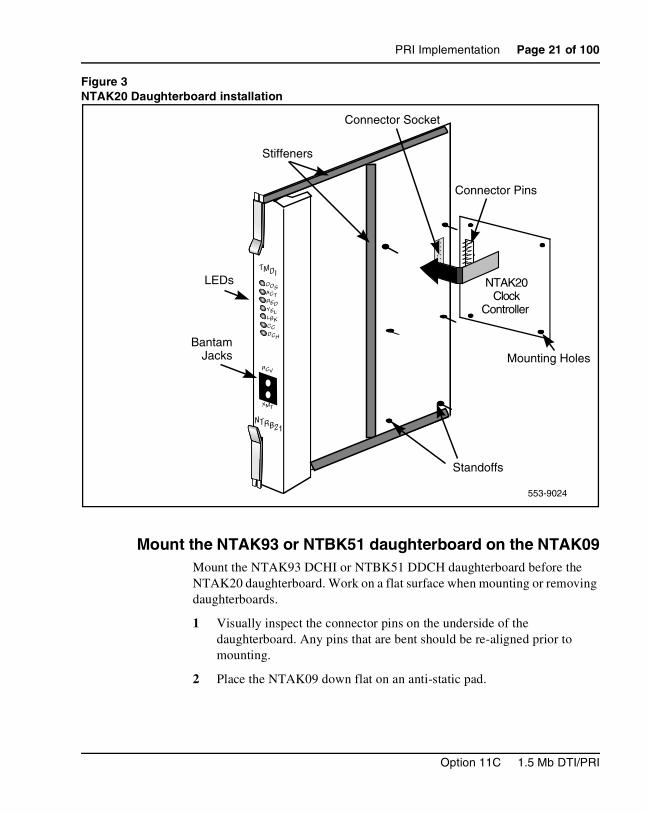
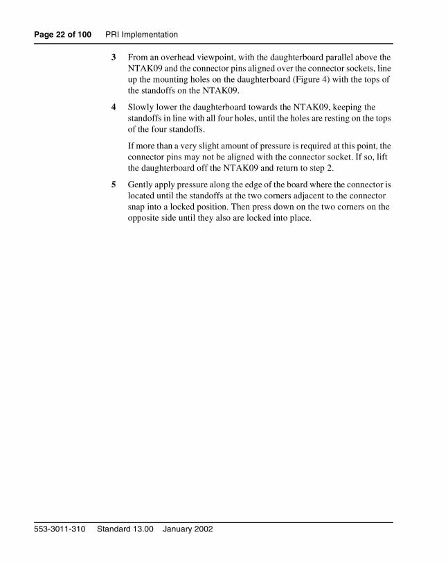
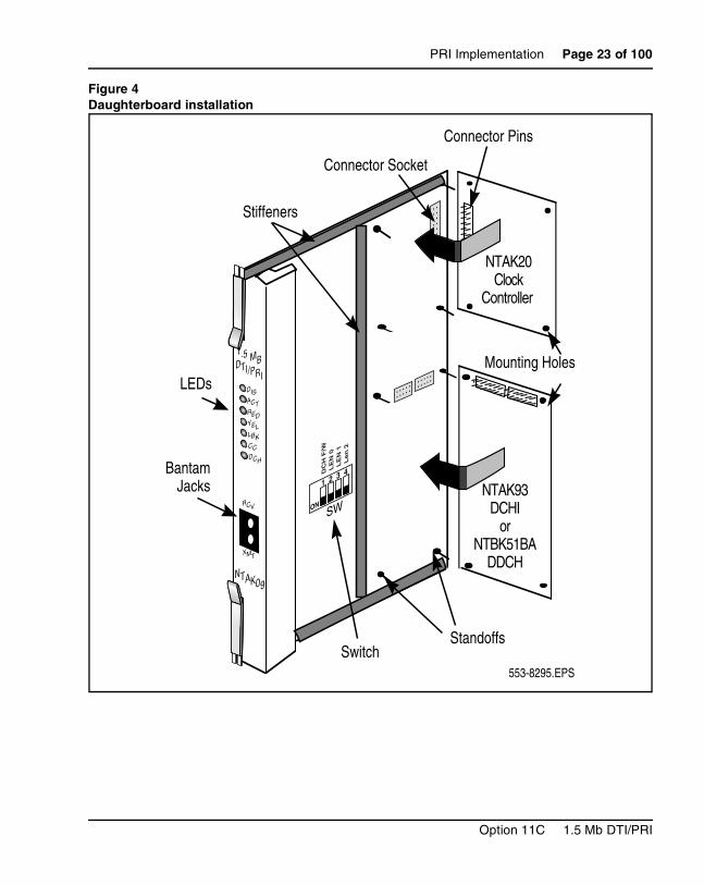
Mount the NTAK93 or NTBK51 daughterboard on the NTAK09Mount the NTAK93 DCHI or NTBK51 DDCH daughterboard before the NTAK20 daughterboard. Work on a flat surface when mounting or removing daughterboards.
1 Visually inspect the connector pins on the underside of the daughterboard. Any pins that are bent should be re-aligned prior to mounting.
2 Place the NTAK09 down flat on an anti-static pad.
OOSACTREDYELLBKCCDCH
RCV
XMT
NTRB21
TMDI
SWON
1 2 3 4
DC
H F
/WL
EN
0L
EN
1L
en 2
553-9024
Stiffeners
NTAK20Clock
Controller
Mounting Holes
Connector Socket
Connector Pins
LEDs
BantamJacks
Standoffs
Option 11C 1.5 Mb DTI/PRI
Page 22 of 100 PRI Implementation
3 From an overhead viewpoint, with the daughterboard parallel above the NTAK09 and the connector pins aligned over the connector sockets, line up the mounting holes on the daughterboard (Figure 4) with the tops of the standoffs on the NTAK09.
4 Slowly lower the daughterboard towards the NTAK09, keeping the standoffs in line with all four holes, until the holes are resting on the tops of the four standoffs.
If more than a very slight amount of pressure is required at this point, the connector pins may not be aligned with the connector socket. If so, lift the daughterboard off the NTAK09 and return to step 2.
5 Gently apply pressure along the edge of the board where the connector is located until the standoffs at the two corners adjacent to the connector snap into a locked position. Then press down on the two corners on the opposite side until they also are locked into place.
553-3011-310 Standard 13.00 January 2002
PRI Implementation Page 23 of 100
Figure 4Daughterboard installation
NTAK20Clock
Controller
NTAK93DCHI
orNTBK51BA
DDCH
DISACTREDYELLBKCCDCH
RCV
XMT
NTAK09
1.5 MBDTI/PRI
ON
1 2 3 4DC
H F
/WL
EN
0L
EN
1L
en
2
SWON
1 2 3 4
DC
H F
/WL
EN
0L
EN
1L
en
2
553-8295.EPS
SW
Stiffeners
Mounting Holes
Connector Socket
Connector Pins
LEDs
BantamJacks
StandoffsSwitch
Option 11C 1.5 Mb DTI/PRI
Page 24 of 100 PRI Implementation
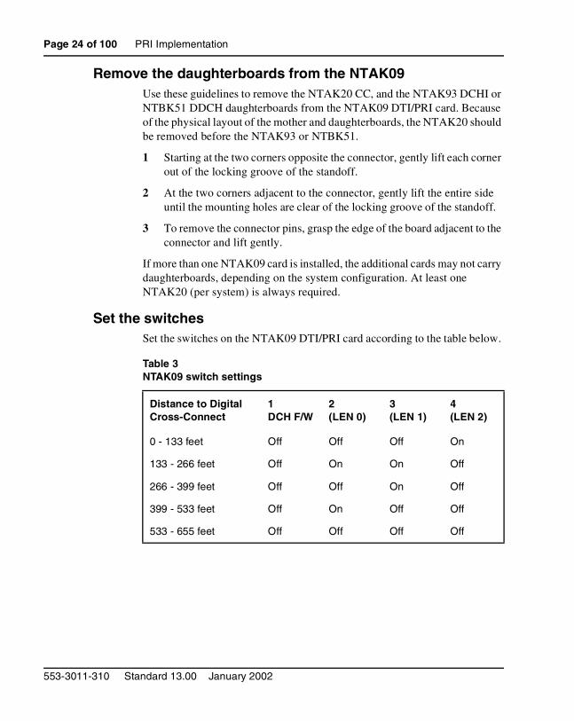
Remove the daughterboards from the NTAK09Use these guidelines to remove the NTAK20 CC, and the NTAK93 DCHI or NTBK51 DDCH daughterboards from the NTAK09 DTI/PRI card. Because of the physical layout of the mother and daughterboards, the NTAK20 should be removed before the NTAK93 or NTBK51.
1 Starting at the two corners opposite the connector, gently lift each corner out of the locking groove of the standoff.
2 At the two corners adjacent to the connector, gently lift the entire side until the mounting holes are clear of the locking groove of the standoff.
3 To remove the connector pins, grasp the edge of the board adjacent to the connector and lift gently.
If more than one NTAK09 card is installed, the additional cards may not carry daughterboards, depending on the system configuration. At least one NTAK20 (per system) is always required.
Set the switchesSet the switches on the NTAK09 DTI/PRI card according to the table below.
Table 3NTAK09 switch settings
Distance to Digital Cross-Connect
1DCH F/W
2(LEN 0)
3(LEN 1)
4(LEN 2)
0 - 133 feet Off Off Off On
133 - 266 feet Off On On Off
266 - 399 feet Off Off On Off
399 - 533 feet Off On Off Off
533 - 655 feet Off Off Off Off
553-3011-310 Standard 13.00 January 2002
PRI Implementation Page 25 of 100
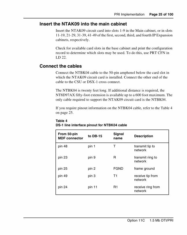
Insert the NTAK09 into the main cabinetInsert the NTAK09 circuit card into slots 1-9 in the Main cabinet, or in slots 11-19, 21-29, 31-39, 41-49 of the first, second, third, and fourth IP Expansion cabinets, respectively.
Check for available card slots in the base cabinet and print the configuration record to determine which slots may be used. To do this, use PRT CFN in LD 22.
Connect the cablesConnect the NTBK04 cable to the 50-pin amphenol below the card slot in which the NTAK09 circuit card is installed. Connect the other end of the cable to the CSU or DSX-1 cross connect.
The NTBK04 is twenty feet long. If additional distance is required, the NT8D97AX fifty-foot extension is available up to a 600 foot maximum. The only cable required to support the NTAK09 circuit card is the NTBK04.
If you require pinout information on the NTBK04 cable, refer to the Table 4 on page 25.
Table 4DS-1 line interface pinout for NTBK04 cable
From 50-pin MDF connector
to DB-15Signal name
Description
pin 48 pin 1 T transmit tip to network
pin 23 pin 9 R transmit ring to network
pin 25 pin 2 FGND frame ground
pin 49 pin 3 T1 receive tip from network
pin 24 pin 11 R1 receive ring from network
Option 11C 1.5 Mb DTI/PRI
Page 26 of 100 PRI Implementation
Install IP daughterboardsRefer to Option 11C Planning and Installation (553-3021-210).
Software enable the DTI/PRI cardsSoftware enable the NTRB21 TMDI card
1 Enable the NTRB21 TMDI card using the following overlay and command:
LD 96 ENL TMDI x
where x is the NTRB21 TMDI card number (DLOP). The card number associated with a NTRB21 TMDI card is based on the slot in which the card is installed (1-49).
2 If in PRI mode, S/W enable the associated D-channel using the following overlay and commands:
LD 96 ENL DCH y
Where y is the DCH port number that was assigned in LD 17.
Within about 30 seconds, the D-channel layer 3 should be established. To confirm, request the current status of the D-channel by using the LD 60 command STAT DCH (N).
The system should respond DCH N EST OPER, meaning that the D-channel is established and operational.
Software enable the NTAK09 cardUse step 1 to enable NTAK09 DTI/PRI card. If the clock controller and D-channel interface are not enabled in step 1, go to step 2.
Step 1
• Software enable all NTAK09 DTI/PRI cards using LD 60:ENLL C
Where C is the DTI/PRI card number (DLOP). The card number associated with a DTI/PRI card is based on the slot in which the card is installed.
553-3011-310 Standard 13.00 January 2002
PRI Implementation Page 27 of 100
Note: The DCHI and PRI cards must be programmed prior to software enabling the NTAK09. Refer to the section “Program Basic PRI” on page 27 for further information.
• Under normal conditions, this step enables the clock controller and D-channel interface. If enable fails, go to step 2.
Step 2: (if required):
Software enable the clock controller using LD 60. Enable clock tracking on primary digital card by issuing the following command:
ENL CC 0
• Software enable the NTAK93 (DCHI) daughterboard using LD 96 command
ENL DCHI N
(where N is the DCHI I/O address).
• Within about 30 seconds, the D-channel layer 3 should be established. To confirm, request the current status of the D-channel by issuing the command
• The system should respond DCH N EST OPER, meaning that the D-channel is established and operational.
Program Basic PRIUse this procedure to configure the PRI cards, DCHI interface, DCH link and ISDN trunk route and trunks (B-channels) that are required to implement PRI between Meridian 1 systems. No feature applications other than Basic Call Service are included in the programming.
PrerequisitesPRI cards must be configured before defining the DCH links or PRI applications.
Prompts which do not show a response can be left at default. For more information on any of these prompts, refer to Administration (553-3001-311).
Option 11C 1.5 Mb DTI/PRI
Page 28 of 100 PRI Implementation
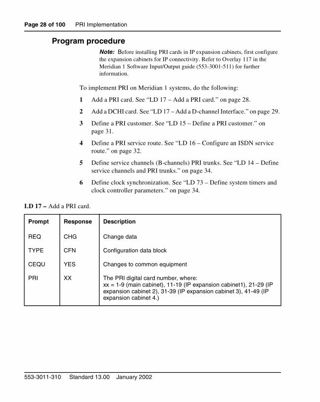
Program procedureNote: Before installing PRI cards in IP expansion cabinets, first configure the expansion cabinets for IP connectivity. Refer to Overlay 117 in the Meridian 1 Software Input/Output guide (553-3001-511) for further information.
To implement PRI on Meridian 1 systems, do the following:
1 Add a PRI card. See “LD 17 – Add a PRI card.” on page 28.
2 Add a DCHI card. See “LD 17 – Add a D-channel Interface.” on page 29.
3 Define a PRI customer. See “LD 15 – Define a PRI customer.” on page 31.
4 Define a PRI service route. See “LD 16 – Configure an ISDN service route.” on page 32.
5 Define service channels (B-channels) PRI trunks. See “LD 14 – Define service channels and PRI trunks.” on page 34.
6 Define clock synchronization. See “LD 73 – Define system timers and clock controller parameters.” on page 34.
LD 17 – Add a PRI card.
Prompt Response Description
REQ CHG Change data
TYPE CFN Configuration data block
CEQU YES Changes to common equipment
PRI XX The PRI digital card number, where:xx = 1-9 (main cabinet), 11-19 (IP expansion cabinet1), 21-29 (IP expansion cabinet 2), 31-39 (IP expansion cabinet 3), 41-49 (IP expansion cabinet 4.)
553-3011-310 Standard 13.00 January 2002
PRI Implementation Page 29 of 100
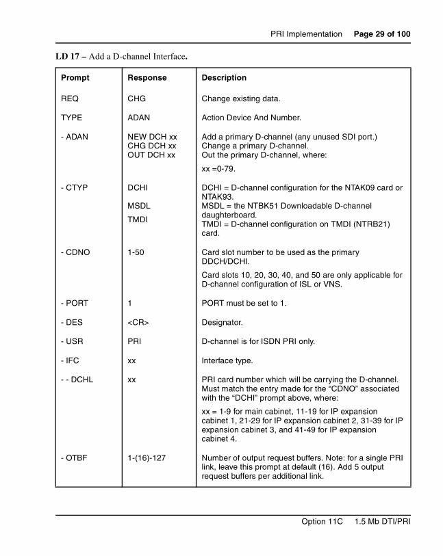
LD 17 – Add a D-channel Interface.
Prompt Response Description
REQ CHG Change existing data.
TYPE ADAN Action Device And Number.
- ADAN NEW DCH xxCHG DCH xxOUT DCH xx
Add a primary D-channel (any unused SDI port.)Change a primary D-channel.Out the primary D-channel, where:
xx =0-79.
- CTYP DCHI
MSDL
TMDI
DCHI = D-channel configuration for the NTAK09 card or NTAK93.MSDL = the NTBK51 Downloadable D-channel daughterboard.TMDI = D-channel configuration on TMDI (NTRB21) card.
- CDNO 1-50 Card slot number to be used as the primary DDCH/DCHI.
Card slots 10, 20, 30, 40, and 50 are only applicable for D-channel configuration of ISL or VNS.
- PORT 1 PORT must be set to 1.
- DES <CR> Designator.
- USR PRI D-channel is for ISDN PRI only.
- IFC xx Interface type.
- - DCHL xx PRI card number which will be carrying the D-channel. Must match the entry made for the “CDNO” associated with the “DCHI” prompt above, where:
xx = 1-9 for main cabinet, 11-19 for IP expansion cabinet 1, 21-29 for IP expansion cabinet 2, 31-39 for IP expansion cabinet 3, and 41-49 for IP expansion cabinet 4.
- OTBF 1-(16)-127 Number of output request buffers. Note: for a single PRI link, leave this prompt at default (16). Add 5 output request buffers per additional link.
Option 11C 1.5 Mb DTI/PRI
Page 30 of 100 PRI Implementation
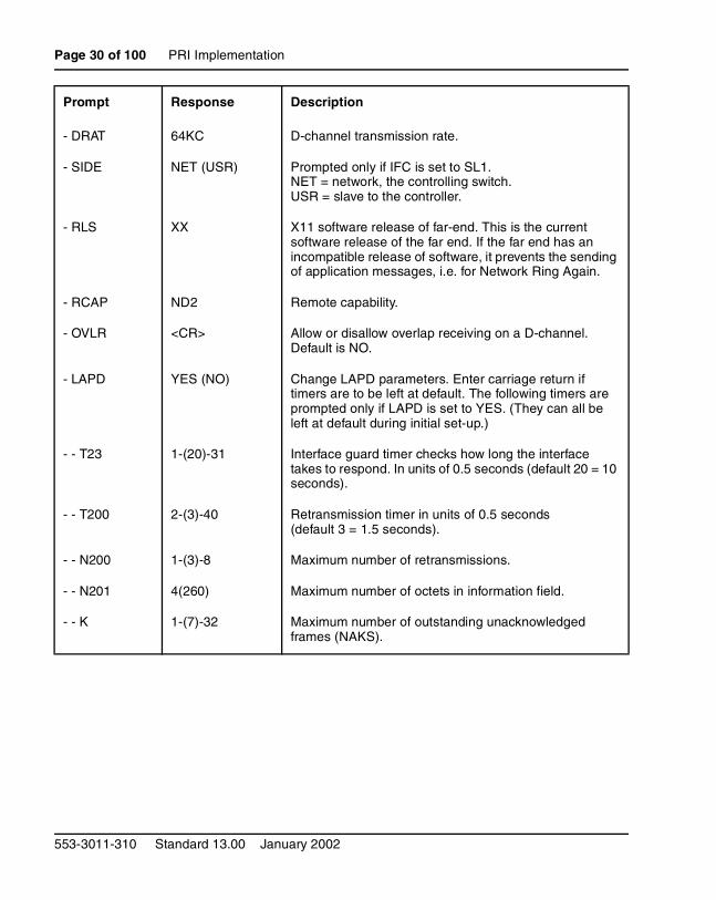
- DRAT 64KC D-channel transmission rate.
- SIDE NET (USR) Prompted only if IFC is set to SL1.NET = network, the controlling switch.USR = slave to the controller.
- RLS XX X11 software release of far-end. This is the current software release of the far end. If the far end has an incompatible release of software, it prevents the sending of application messages, i.e. for Network Ring Again.
- RCAP ND2 Remote capability.
- OVLR <CR> Allow or disallow overlap receiving on a D-channel. Default is NO.
- LAPD YES (NO) Change LAPD parameters. Enter carriage return if timers are to be left at default. The following timers are prompted only if LAPD is set to YES. (They can all be left at default during initial set-up.)
- - T23 1-(20)-31 Interface guard timer checks how long the interface takes to respond. In units of 0.5 seconds (default 20 = 10 seconds).
- - T200 2-(3)-40 Retransmission timer in units of 0.5 seconds (default 3 = 1.5 seconds).
- - N200 1-(3)-8 Maximum number of retransmissions.
- - N201 4(260) Maximum number of octets in information field.
- - K 1-(7)-32 Maximum number of outstanding unacknowledged frames (NAKS).
Prompt Response Description
553-3011-310 Standard 13.00 January 2002
PRI Implementation Page 31 of 100
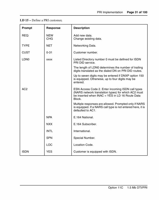
LD 15 – Define a PRI customer.
Prompt Response Description
REQ: NEWCHG
Add new data.Change existing data.
TYPE NET Networking Data.
CUST 0-31 Customer number.
LDN0 xxxx Listed Directory number 0 must be defined for ISDN PRI DID service.
The length of LDN0 determines the number of trailing digits translated as the dialed DN on PRI DID routes.
Up to seven digits may be entered if DNXP option 150 is equipped. Otherwise, up to four digits may be entered.
AC2 ESN Access Code 2. Enter incoming ISDN call types (NARS network translation types) for which AC2 must be inserted when INAC = YES in LD 16 Route Data Block.
Multiple responses are allowed. Prompted only if NARS is equipped. If a NARS call type is not entered here, it is defaulted to AC1.
NPA E.164 National.
NXX E.164 Subscriber.
INTL International.
SPN Special Number.
LOC Location Code.
ISDN YES Customer is equipped with ISDN.
Option 11C 1.5 Mb DTI/PRI

Page 32 of 100 PRI Implementation
LD 16 – Configure an ISDN service route.
- PNI (0) 1-32700 Private Network Identifier. Each customer data block must have a unique PNI when multi-customer option is equipped. PNI = 1 is typical for CUST = 0. It must be matched by the PNI in the far-end RDB.
Note: using the default value of PNI = 0, prevents operation of features like NRAG, NACD and NMS.
- HNPA NPA Telephone area code for this Meridian 1. Sent as part of setup message as calling line identification.
- HNXX NXX Telephone local exchange code for this Meridian 1. Sent as part of setup message as calling line identification.
- - HLOC XXX Home location code (NARS), prompted when PRA = YES
- - LSC 1-9999 One to four digit Local Steering Code, if required in the Coordinated Dialing Plan (CDP). LSCs are required only if the CDP DNs are longer than the local PDNs.
The CLID sent for a CDP call is composed of the LSC defined in LD 15 plus the PDN of the calling set. Various ISDN network features depend on the CLID as the “return address” for sending feature control messages.
Multiple LSCs can be defined in LD 87 for CDP, but only one LSC can be defined here for CLID.
Prompt Response Description
REQ NEWCHG
Add new datachange existing data
TYPE RDB Route data block
TKTP xxx Trunk type.
Prompt Response Description
553-3011-310 Standard 13.00 January 2002
PRI Implementation Page 33 of 100
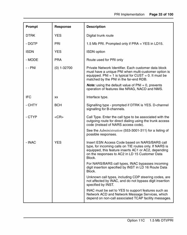
DTRK YES Digital trunk route
- DGTP PRI 1.5 Mb PRI. Prompted only if PRA = YES in LD15.
ISDN YES ISDN option
- MODE PRA Route used for PRI only
- - PNI (0) 1-32700 Private Network Identifier. Each customer data block must have a unique PNI when multi-customer option is equipped. PNI = 1 is typical for CUST = 0. It must be matched by the PNI in the far-end RDB.
Note: using the default value of PNI = 0, prevents operation of features like NRAG, NACD and NMS.
IFC xx Interface type.
- CHTY BCH Signalling type - prompted if DTRK is YES. D-channel signalling for B-channels.
- CTYP <CR> Call Type. Enter the call type to be associated with the outgoing route for direct dialing using the trunk access code (instead of NARS access code).
See the Administration (553-3001-311) for a listing of possible responses.
- INAC YES Insert ESN Access Code based on NARS/BARS call type, for incoming calls on TIE routes only. If NARS is equipped, this feature inserts AC1 or AC2, depending on the responses to AC2 in LD 15 Customer Data Block.
For NARS/BARS call types, INAC bypasses incoming digit insertion specified by INST in LD 16 Route Data Block.
Unknown call types, including CDP steering codes, are not affected by INAC, and do not bypass digit insertion specified by INST.
INAC must be set to YES to support features such as Network ACD and Network Message Services, which depend on non-call associated TCAP facility messages.
Prompt Response Description
Option 11C 1.5 Mb DTI/PRI
Page 34 of 100 PRI Implementation
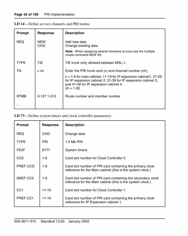
LD 14 – Define service channels and PRI trunks.
LD 73 – Define system timers and clock controller parameters.
Prompt Response Description
REQ NEWCHG
Add new dataChange existing data
Note: When assigning several members at once use the multiple create command NEW XX.
TYPE TIE TIE trunk only, allowed between MSL-1.
TN c ch Enter the PRI trunk card (c) and channel number (ch).
c = 1-9 for main cabinet, 11-19 for IP expansion cabinet1, 21-29 for IP expansion cabinet 2, 31-39 for IP expansion cabinet 3, and 41-49 for IP expansion cabinet 4.ch = 1-30
RTMB 0-127 1-510 Route number and member number
...
Prompt Response Description
REQ CHG Change data
TYPE PRI 1.5 Mb PRI
FEAT SYTI System timers
CC0 1-9 Card slot number for Clock Controller 0.
PREF CCO 1-9 Card slot number of PRI card containing the prImary clock reference for the Main cabinet (this is the system clock.)
SREF CC0 1-9 Card slot number of PRI card containing the secondary clock reference for the Main cabinet (this is the system clock.)
CC1 11-19 Card slot number for Clock Controller 1.
PREF CC1 11-19 Card slot number of PRI card containing the prImary clock reference for IP Expansion cabinet 1.
553-3011-310 Standard 13.00 January 2002
PRI Implementation Page 35 of 100
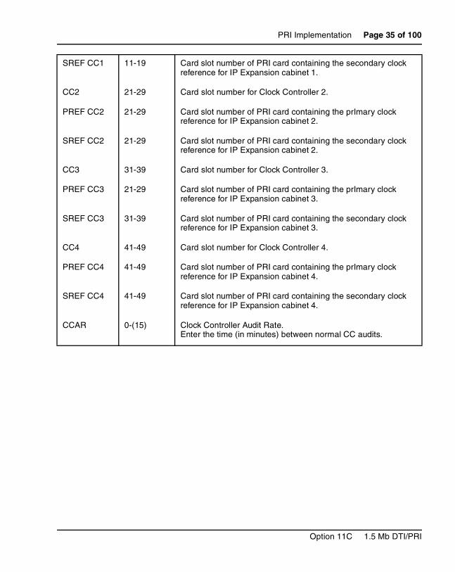
SREF CC1 11-19 Card slot number of PRI card containing the secondary clock reference for IP Expansion cabinet 1.
CC2 21-29 Card slot number for Clock Controller 2.
PREF CC2 21-29 Card slot number of PRI card containing the prImary clock reference for IP Expansion cabinet 2.
SREF CC2 21-29 Card slot number of PRI card containing the secondary clock reference for IP Expansion cabinet 2.
CC3 31-39 Card slot number for Clock Controller 3.
PREF CC3 21-29 Card slot number of PRI card containing the prImary clock reference for IP Expansion cabinet 3.
SREF CC3 31-39 Card slot number of PRI card containing the secondary clock reference for IP Expansion cabinet 3.
CC4 41-49 Card slot number for Clock Controller 4.
PREF CC4 41-49 Card slot number of PRI card containing the prImary clock reference for IP Expansion cabinet 4.
SREF CC4 41-49 Card slot number of PRI card containing the secondary clock reference for IP Expansion cabinet 4.
CCAR 0-(15) Clock Controller Audit Rate. Enter the time (in minutes) between normal CC audits.
Option 11C 1.5 Mb DTI/PRI
Page 36 of 100 PRI Implementation
553-3011-310 Standard 13.00 January 2002
Page 37 of 100
46
DTI ImplementationContents
This section contains information on the following topics:
Overview . . . . . . . . . . . . . . . . . . . . . . . . . . . . . . . . . . . . . . . . . . . . . . . . 37
Hardware Requirements . . . . . . . . . . . . . . . . . . . . . . . . . . . . . . . . . . . . . 38
Cables . . . . . . . . . . . . . . . . . . . . . . . . . . . . . . . . . . . . . . . . . . . . . . . . . . . 38
Channel Service Units . . . . . . . . . . . . . . . . . . . . . . . . . . . . . . . . . . . . . . 38
Hardware description . . . . . . . . . . . . . . . . . . . . . . . . . . . . . . . . . . . . . . . 39
Install DTI hardware . . . . . . . . . . . . . . . . . . . . . . . . . . . . . . . . . . . . . . . 39
Set the switches . . . . . . . . . . . . . . . . . . . . . . . . . . . . . . . . . . . . . . . . . . . 39
Connect the cables . . . . . . . . . . . . . . . . . . . . . . . . . . . . . . . . . . . . . . . . . 39
Software enable the DTI/DTI cards . . . . . . . . . . . . . . . . . . . . . . . . . . . . 40
Software enable the NTRB21 TMDI card . . . . . . . . . . . . . . . . . . . . . . . 40
Software enable the NTAK09 card . . . . . . . . . . . . . . . . . . . . . . . . . . . . 41
Program the DTI . .. . . . . . . . . . . . . . . . . . . . . . . . . . . . . . . . . . . . . . . . . 42
Programming procedure . . . . . . . . . . . . . . . . . . . . . . . . . . . . . . . . . . . . . 42
OverviewThis chapter provides the information required to install DTI on a Meridian 1 Option 11C system, including:
• hardware and software installation
• programming procedures for basic call service
Option 11C 1.5 Mb DTI/PRI
Page 38 of 100 DTI Implementation
This chapter covers the most common type of Nortel Networks DTI installation, a 24-channel Digital Trunk Interface (DTI) installation between two Meridian 1 systems, or a Meridian 1 and a central office.
Since Release 25.30 software, digital trunks are supported in Option 11C IP expansion cabinets.
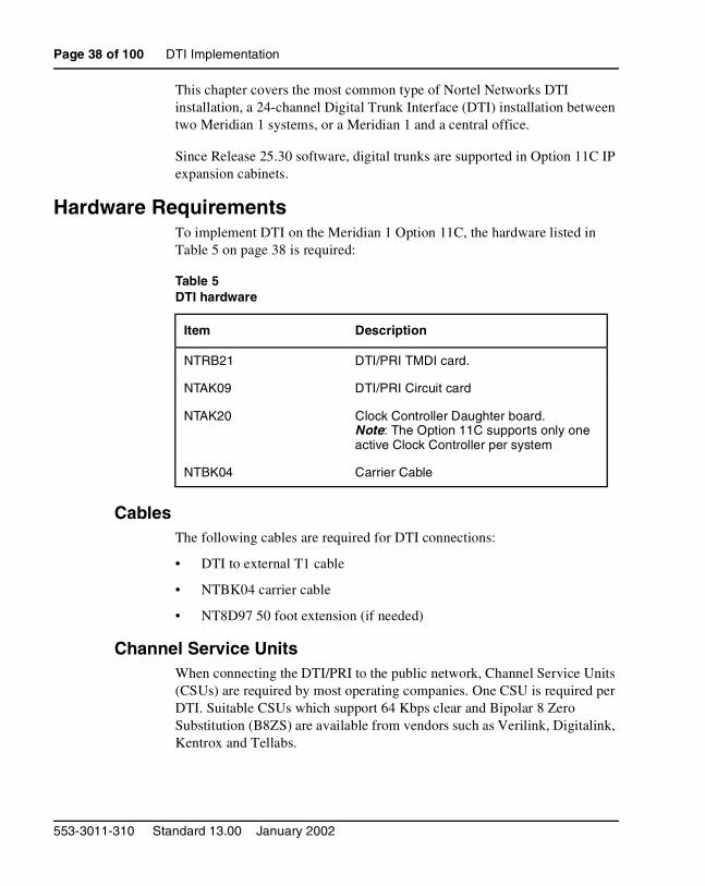
Hardware RequirementsTo implement DTI on the Meridian 1 Option 11C, the hardware listed in Table 5 on page 38 is required:
CablesThe following cables are required for DTI connections:
• DTI to external T1 cable
• NTBK04 carrier cable
• NT8D97 50 foot extension (if needed)
Channel Service UnitsWhen connecting the DTI/PRI to the public network, Channel Service Units (CSUs) are required by most operating companies. One CSU is required per DTI. Suitable CSUs which support 64 Kbps clear and Bipolar 8 Zero Substitution (B8ZS) are available from vendors such as Verilink, Digitalink, Kentrox and Tellabs.
Table 5DTI hardware
Item Description
NTRB21 DTI/PRI TMDI card.
NTAK09 DTI/PRI Circuit card
NTAK20 Clock Controller Daughter board. Note: The Option 11C supports only one active Clock Controller per system
NTBK04 Carrier Cable
553-3011-310 Standard 13.00 January 2002
DTI Implementation Page 39 of 100
Note: Contact your Nortel Networks Sales representative for specific local CSU requirements.
Hardware descriptionRefer to “Hardware description” on page 12.
Install DTI hardwareFor information on how to install the NTRB21 DTI/DTI card, refer to “Insert/remove the NTRB21 TMDI card” on page 18 of the “Install PRI hardware” chapter. For information on how to install the NTAK09 DTI/DTI card, refer to “Insert the NTAK09 into the main cabinet” on page 25.
For information on how to install the NTAK20 Clock Controller, refer to “Mount the NTAK20 daughterboard on the NTRB21” on page 20.
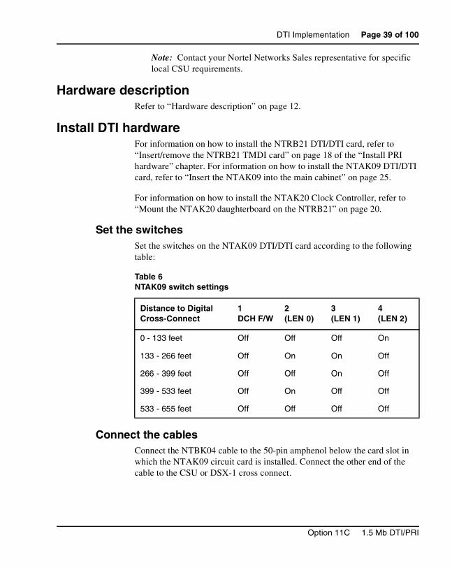
Set the switchesSet the switches on the NTAK09 DTI/DTI card according to the following table:
Connect the cablesConnect the NTBK04 cable to the 50-pin amphenol below the card slot in which the NTAK09 circuit card is installed. Connect the other end of the cable to the CSU or DSX-1 cross connect.
Table 6NTAK09 switch settings
Distance to Digital Cross-Connect
1DCH F/W
2(LEN 0)
3(LEN 1)
4(LEN 2)
0 - 133 feet Off Off Off On
133 - 266 feet Off On On Off
266 - 399 feet Off Off On Off
399 - 533 feet Off On Off Off
533 - 655 feet Off Off Off Off
Option 11C 1.5 Mb DTI/PRI
Page 40 of 100 DTI Implementation
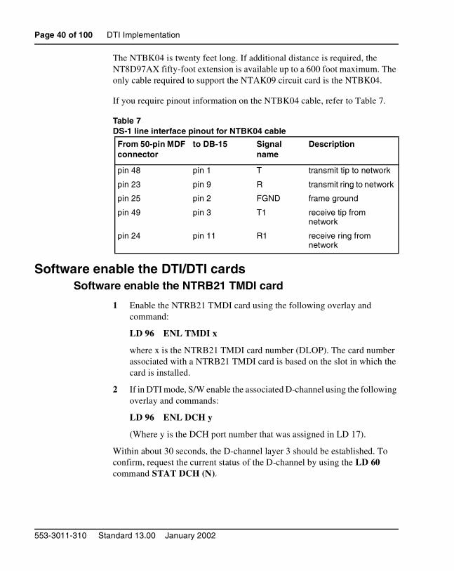
The NTBK04 is twenty feet long. If additional distance is required, the NT8D97AX fifty-foot extension is available up to a 600 foot maximum. The only cable required to support the NTAK09 circuit card is the NTBK04.
If you require pinout information on the NTBK04 cable, refer to Table 7.
Table 7DS-1 line interface pinout for NTBK04 cable
Software enable the DTI/DTI cardsSoftware enable the NTRB21 TMDI card
1 Enable the NTRB21 TMDI card using the following overlay and command:
LD 96 ENL TMDI x
where x is the NTRB21 TMDI card number (DLOP). The card number associated with a NTRB21 TMDI card is based on the slot in which the card is installed.
2 If in DTI mode, S/W enable the associated D-channel using the following overlay and commands:
LD 96 ENL DCH y
(Where y is the DCH port number that was assigned in LD 17).
Within about 30 seconds, the D-channel layer 3 should be established. To confirm, request the current status of the D-channel by using the LD 60 command STAT DCH (N).
From 50-pin MDF connector
to DB-15 Signal name
Description
pin 48 pin 1 T transmit tip to network
pin 23 pin 9 R transmit ring to network
pin 25 pin 2 FGND frame ground
pin 49 pin 3 T1 receive tip from network
pin 24 pin 11 R1 receive ring from network
553-3011-310 Standard 13.00 January 2002
DTI Implementation Page 41 of 100
The system should respond DCH N EST OPER, meaning that the D-channel is established and operational.
Software enable the NTAK09 cardUse step 1 to enable NTAK09 DTI/DTI card. If the clock controller and D-channel interface are not enabled in step 1, go to step 2.
Step 1:
• Software enable all NTAK09 DTI/DTI cards using LD 60:ENLL C
Where C is the DTI/DTI card number (DLOP). The card number associated with a DTI/DTI card is based on the slot in which the card is installed.
Note: The DCHI and DTI cards must be programmed prior to software enabling the NTAK09. Refer to the section “Program Basic PRI” on page 27 for further information.
• Under normal conditions, this step enables the clock controller and D-channel interface. If enable fails, go to step 2.
Step 2: (if required):
Software enable the clock controller using LD 60. Enable clock tracking on primary digital card by issuing the following command:
ENL CC 0
• Software enable the NTAK93 (DCHI) daughterboard using LD 96 command
ENL DCHI N
(where N is the DCHI I/O address).
Option 11C 1.5 Mb DTI/PRI
Page 42 of 100 DTI Implementation
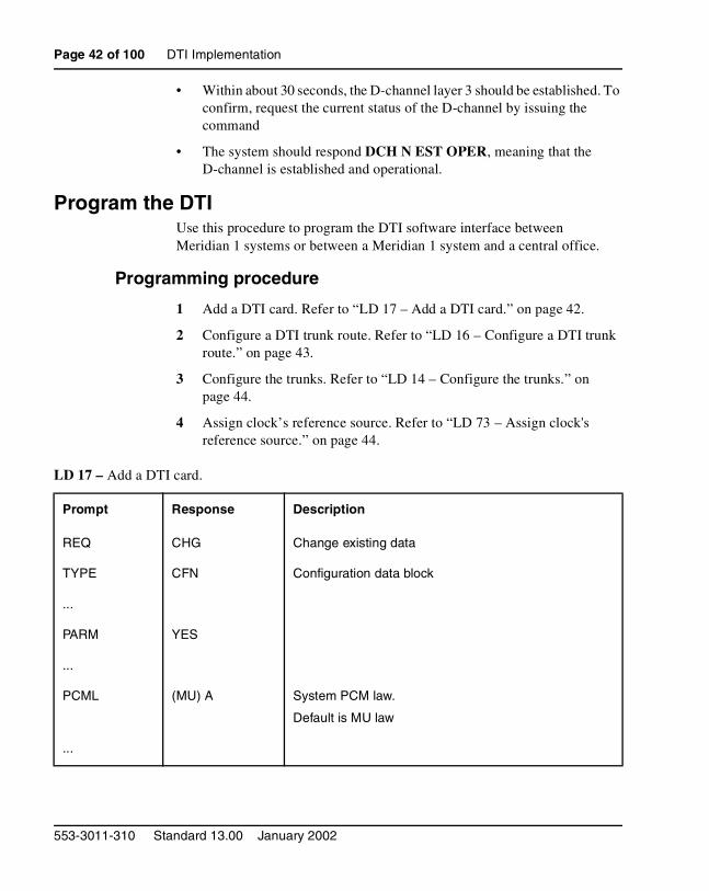
• Within about 30 seconds, the D-channel layer 3 should be established. To confirm, request the current status of the D-channel by issuing the command
• The system should respond DCH N EST OPER, meaning that the D-channel is established and operational.
Program the DTIUse this procedure to program the DTI software interface between Meridian 1 systems or between a Meridian 1 system and a central office.
Programming procedure
1 Add a DTI card. Refer to “LD 17 – Add a DTI card.” on page 42.
2 Configure a DTI trunk route. Refer to “LD 16 – Configure a DTI trunk route.” on page 43.
3 Configure the trunks. Refer to “LD 14 – Configure the trunks.” on page 44.
4 Assign clock’s reference source. Refer to “LD 73 – Assign clock's reference source.” on page 44.
LD 17 – Add a DTI card.
Prompt Response Description
REQ CHG Change existing data
TYPE CFN Configuration data block
...
PARM YES
...
PCML (MU) A System PCM law.
Default is MU law
...
553-3011-310 Standard 13.00 January 2002
DTI Implementation Page 43 of 100
LD 16 – Configure a DTI trunk route.
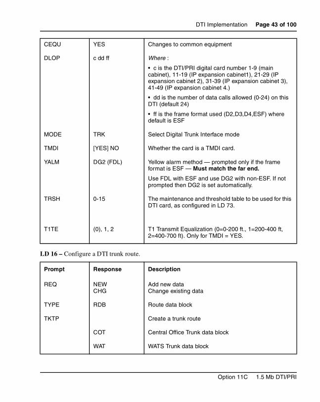
CEQU YES Changes to common equipment
DLOP c dd ff Where :
• c is the DTI/PRI digital card number 1-9 (main cabinet), 11-19 (IP expansion cabinet1), 21-29 (IP expansion cabinet 2), 31-39 (IP expansion cabinet 3), 41-49 (IP expansion cabinet 4.)
• dd is the number of data calls allowed (0-24) on this DTI (default 24)
• ff is the frame format used (D2,D3,D4,ESF) where default is ESF
MODE TRK Select Digital Trunk Interface mode
TMDI [YES] NO Whether the card is a TMDI card.
YALM DG2 (FDL) Yellow alarm method — prompted only if the frame format is ESF — Must match the far end.
Use FDL with ESF and use DG2 with non-ESF. If not prompted then DG2 is set automatically.
TRSH 0-15 The maintenance and threshold table to be used for this DTI card, as configured in LD 73.
T1TE (0), 1, 2 T1 Transmit Equalization (0=0-200 ft., 1=200-400 ft, 2=400-700 ft). Only for TMDI = YES.
Prompt Response Description
REQ NEWCHG
Add new dataChange existing data
TYPE RDB Route data block
TKTP Create a trunk route
COT Central Office Trunk data block
WAT WATS Trunk data block
Option 11C 1.5 Mb DTI/PRI
Page 44 of 100 DTI Implementation
LD 14 – Configure the trunks.
LD 73 – Assign clock's reference source.
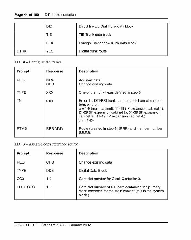
DID Direct Inward Dial Trunk data block
TIE TIE Trunk data block
FEX Foreign Exchange= Trunk data block
DTRK YES Digital trunk route
Prompt Response Description
REQ NEWCHG
Add new dataChange existing data
TYPE XXX One of the trunk types defined in step 3.
TN c ch Enter the DTI/PRI trunk card (c) and channel number (ch), where:c = 1-9 (main cabinet), 11-19 (IP expansion cabinet 1), 21-29 (IP expansion cabinet 2), 31-39 (IP expansion cabinet 3), 41-49 (IP expansion cabinet 4.)ch = 1-24
RTMB RRR MMM Route (created in step 3) (RRR) and member number (MMM).
Prompt Response Description
REQ CHG Change existing data
TYPE DDB Digital Data Block
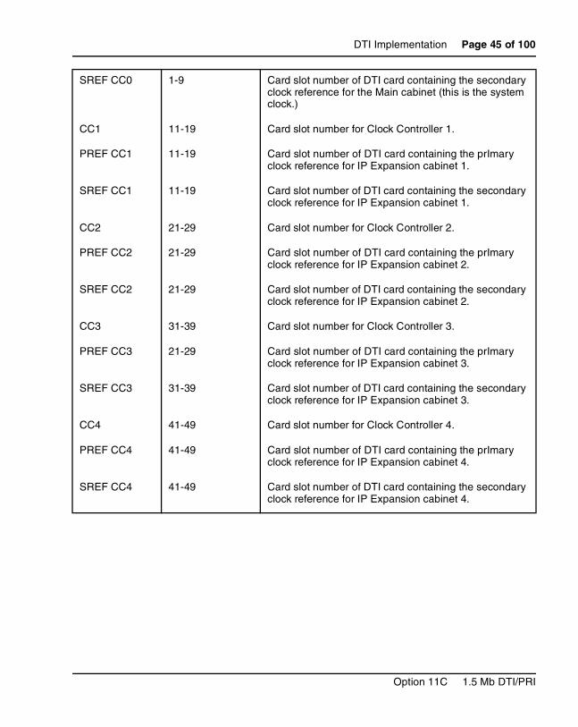
CC0 1-9 Card slot number for Clock Controller 0.
PREF CCO 1-9 Card slot number of DTI card containing the prImary clock reference for the Main cabinet (this is the system clock.)
553-3011-310 Standard 13.00 January 2002
DTI Implementation Page 45 of 100
SREF CC0 1-9 Card slot number of DTI card containing the secondary clock reference for the Main cabinet (this is the system clock.)
CC1 11-19 Card slot number for Clock Controller 1.
PREF CC1 11-19 Card slot number of DTI card containing the prImary clock reference for IP Expansion cabinet 1.
SREF CC1 11-19 Card slot number of DTI card containing the secondary clock reference for IP Expansion cabinet 1.
CC2 21-29 Card slot number for Clock Controller 2.
PREF CC2 21-29 Card slot number of DTI card containing the prImary clock reference for IP Expansion cabinet 2.
SREF CC2 21-29 Card slot number of DTI card containing the secondary clock reference for IP Expansion cabinet 2.
CC3 31-39 Card slot number for Clock Controller 3.
PREF CC3 21-29 Card slot number of DTI card containing the prImary clock reference for IP Expansion cabinet 3.
SREF CC3 31-39 Card slot number of DTI card containing the secondary clock reference for IP Expansion cabinet 3.
CC4 41-49 Card slot number for Clock Controller 4.
PREF CC4 41-49 Card slot number of DTI card containing the prImary clock reference for IP Expansion cabinet 4.
SREF CC4 41-49 Card slot number of DTI card containing the secondary clock reference for IP Expansion cabinet 4.
Option 11C 1.5 Mb DTI/PRI

Page 46 of 100 DTI Implementation
553-3011-310 Standard 13.00 January 2002
Page 47 of 100
78
DTI/PRI MaintenanceContents
This section contains information on the following topics:
Reference list . . . . . . . . . . . . . . . . . . . . . . . . . . . . . . . . . . . . . . . . . . . . . 48
Maintenance overview . . . . . . . . . . . . . . . . . . . . . . . . . . . . . . . . . . . . . . 48
Monitor the Option 11C DTI/PRI operation . . . . . . . . . . . . . . . . . . . . . 48
Maintenance messages . . . . . . . . . . . . . . . . . . . . . . . . . . . . . . . . . . . . . . 48
Alarms . . . . . . . . . . . . . . . . . . . . . . . . . . . . . . . . . . . . . . . . . . . . . . . . . . 51
Option 11C DTI/PRI maintenance tools . . . . . . . . . . . . . . . . . . . . . . . . 52
Maintenance commands . . . . . . . . . . . . . . . . . . . . . . . . . . . . . . . . . . . . . 52
TMDI maintenance commands . . . . . . . . . . . . . . . . . . . . . . . . . . . . . . . 56
D-channel monitoring on the TMDI card . . . . . . . . . . . . . . . . . . . . . . . 56
NTAK09 DTI/PRI power on self-test . . . . . . . . . . . . . . . . . . . . . . . . . . 57
NTAK20 power on self-test . . . . . . . . . . . . . . . . . . . . . . . . . . . . . . . . . . 58
NTAK93 self-test . . . . . . . . . . . . . . . . . . . . . . . . . . . . . . . . . . . . . . . . . . 58
DTI/PRI local self-test . . . . . . . . . . . . . . . . . . . . . . . . . . . . . . . . . . . . . . 59
DTI/PRI automatic local loopback test . . . . . . . . . . . . . . . . . . . . . . . . . 59
DTI/PRI error detection . . . . . . . . . . . . . . . . . . . . . . . . . . . . . . . . . . . . . 63
Frame slip . . . . . . . . . . . . . . . . . . . . . . . . . . . . . . . . . . . . . . . . . . . . . . . . 66
Frame slippage improvement timers . . . . . . . . . . . . . . . . . . . . . . . . . . . 70
Frame alignment . .. . . . . . . . . . . . . . . . . . . . . . . . . . . . . . . . . . . . . . . . . 71
Automatic clock recovery . . . . . . . . . . . . . . . . . . . . . . . . . . . . . . . . . . . 75
Replace equipment . . . . . . . . . . . . . . . . . . . . . . . . . . . . . . . . . . . . . . . . . 76
Option 11C 1.5 Mb DTI/PRI
Page 48 of 100 DTI/PRI Maintenance
Reference listThe following are the references in this section:
• X11 System Messages Guide (553-3001-411)
Maintenance overviewFrom a maintenance perspective, Option 11C DTI/PRI operation consists of these major aspects:
• hardware and software states
• near-end and far-end status
• link and/or span integrity
• clocking status
• frame alignment
Option 11C PRI operation is monitored and reported on through maintenance messages, out-of-service alarms, and circuit card faceplate LEDs. Bantam monitor jacks are located on the faceplate of the NTAK09.
Option 11C maintenance provides several tools, either manual or automatic, for maintaining effective PRI operation. These tools are service change and maintenance commands that are accessible through the software overlays and resident diagnostic routines.
Monitor the Option 11C DTI/PRI operationMaintenance messages
The following sections describe the maintenance messages that may appear on the Option 11C maintenance TTY as a result of DTI or PRI operation.
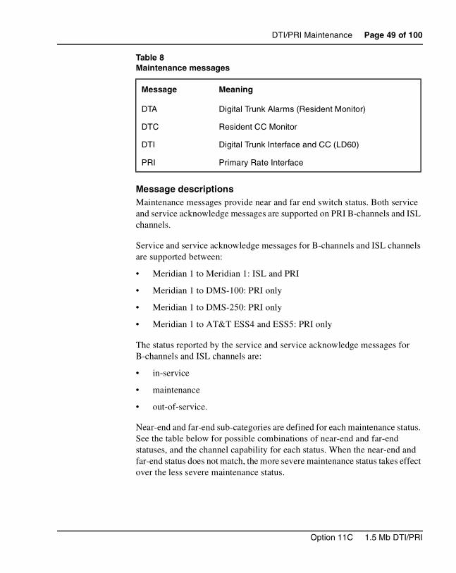
D-channel status and error conditions are reported as DCH messages. PRI status and error conditions are shown in Table 8. (Additional information on PRI and DCH messages can be found in the X11 System Messages Guide (553-3001-411).
553-3011-310 Standard 13.00 January 2002
DTI/PRI Maintenance Page 49 of 100
Message descriptionsMaintenance messages provide near and far end switch status. Both service and service acknowledge messages are supported on PRI B-channels and ISL channels.
Service and service acknowledge messages for B-channels and ISL channels are supported between:
• Meridian 1 to Meridian 1: ISL and PRI
• Meridian 1 to DMS-100: PRI only
• Meridian 1 to DMS-250: PRI only
• Meridian 1 to AT&T ESS4 and ESS5: PRI only
The status reported by the service and service acknowledge messages for B-channels and ISL channels are:
• in-service
• maintenance
• out-of-service.
Near-end and far-end sub-categories are defined for each maintenance status. See the table below for possible combinations of near-end and far-end statuses, and the channel capability for each status. When the near-end and far-end status does not match, the more severe maintenance status takes effect over the less severe maintenance status.
Table 8Maintenance messages
Message Meaning
DTA Digital Trunk Alarms (Resident Monitor)
DTC Resident CC Monitor
DTI Digital Trunk Interface and CC (LD60)
PRI Primary Rate Interface
Option 11C 1.5 Mb DTI/PRI
Page 50 of 100 DTI/PRI Maintenance
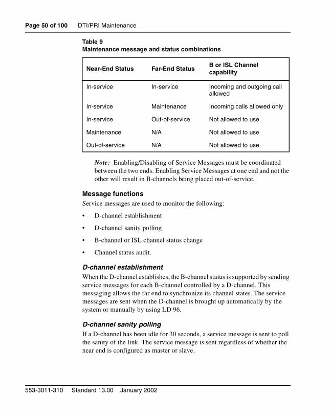
Note: Enabling/Disabling of Service Messages must be coordinated between the two ends. Enabling Service Messages at one end and not the other will result in B-channels being placed out-of-service.
Message functionsService messages are used to monitor the following:
• D-channel establishment
• D-channel sanity polling
• B-channel or ISL channel status change
• Channel status audit.
D-channel establishmentWhen the D-channel establishes, the B-channel status is supported by sending service messages for each B-channel controlled by a D-channel. This messaging allows the far end to synchronize its channel states. The service messages are sent when the D-channel is brought up automatically by the system or manually by using LD 96.
D-channel sanity pollingIf a D-channel has been idle for 30 seconds, a service message is sent to poll the sanity of the link. The service message is sent regardless of whether the near end is configured as master or slave.
Table 9Maintenance message and status combinations
Near-End Status Far-End StatusB or ISL Channel capability
In-service In-service Incoming and outgoing call allowed
In-service Maintenance Incoming calls allowed only
In-service Out-of-service Not allowed to use
Maintenance N/A Not allowed to use
Out-of-service N/A Not allowed to use
553-3011-310 Standard 13.00 January 2002
DTI/PRI Maintenance Page 51 of 100
B-channel or ISL channel status changeWhenever there is a status change for a B-channel or an ISL channel, the new status is reported to the far end via a service message. Status change can occur through service change or maintenance operations, such as the addition or deletion of a channel in LD 14, or disabling of the associated loop, shelf, card or unit in LD 30, LD 32, LD 36, LD 41, or LD 60.
Channel status auditLD 30 is enhanced to allow channel status audit to be initiated. The channels associated with each D-channel are examined and their status is reported to the far end via service messages.
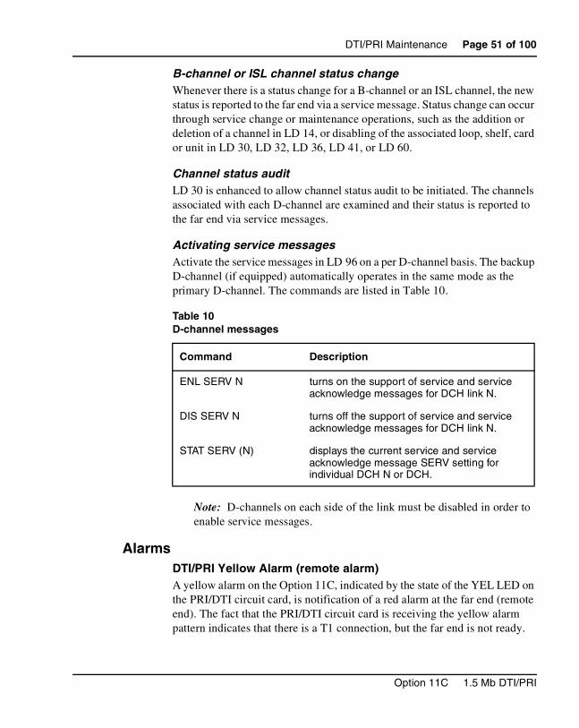
Activating service messagesActivate the service messages in LD 96 on a per D-channel basis. The backup D-channel (if equipped) automatically operates in the same mode as the primary D-channel. The commands are listed in Table 10.
Note: D-channels on each side of the link must be disabled in order to enable service messages.
AlarmsDTI/PRI Yellow Alarm (remote alarm)A yellow alarm on the Option 11C, indicated by the state of the YEL LED on the PRI/DTI circuit card, is notification of a red alarm at the far end (remote end). The fact that the PRI/DTI circuit card is receiving the yellow alarm pattern indicates that there is a T1 connection, but the far end is not ready.
Table 10D-channel messages
Command Description
ENL SERV N turns on the support of service and service acknowledge messages for DCH link N.
DIS SERV N turns off the support of service and service acknowledge messages for DCH link N.
STAT SERV (N) displays the current service and service acknowledge message SERV setting for individual DCH N or DCH.
Option 11C 1.5 Mb DTI/PRI
Page 52 of 100 DTI/PRI Maintenance
It is possible, however, that the T1 connection is one-way only — that is, receiving only, since this end is receiving the alarm. The yellow alarm is transported in one of two ways: using digit-2 or the facility data link (DG2 or FDL).
When the PRI/DTI circuit card receives a yellow alarm, the channels are placed into the maintenance busy state.
Each time a yellow alarm is generated, a counter is incriminated. When the yellow alarm 24-hour threshold (prompt RALM in LD 73) is reached, the PRI/DTI circuit card must be restored to service manually.
DTI/PRI Red Alarm (local alarm)A red alarm (local alarm) indicates that the digital trunks or B-channels have been taken out of service (OOS) due to a loss of frame alignment lasting more than three seconds, or due to some facility performance OOS threshold being exceeded.
Maintenance and OOS messages are discussed later in this chapter.
Option 11C DTI/PRI maintenance toolsMaintenance commands
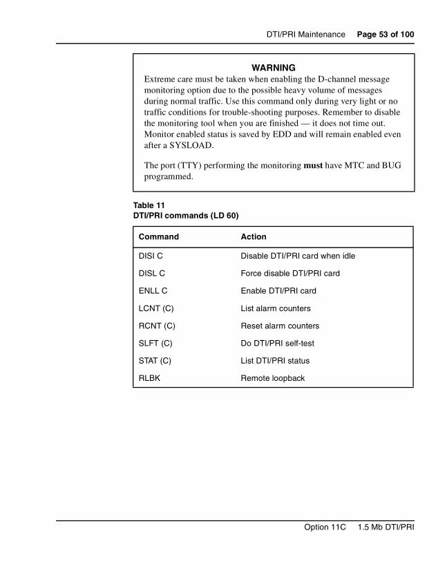
Tables 11on page 53 through Table 13 on page 55 provide quick reference lists of important DTI/PRI commands. Table 14 on page 56 and Table 15 on page 56 pertain to the NTRB51 TMDI card.
WARNINGYou must disable the D-channel and clock-controller daughterboards before unseating circuit cards, otherwise the system will INIT and momentarily interrupt call processing.
553-3011-310 Standard 13.00 January 2002
DTI/PRI Maintenance Page 53 of 100
WARNINGExtreme care must be taken when enabling the D-channel message monitoring option due to the possible heavy volume of messages during normal traffic. Use this command only during very light or no traffic conditions for trouble-shooting purposes. Remember to disable the monitoring tool when you are finished — it does not time out. Monitor enabled status is saved by EDD and will remain enabled even after a SYSLOAD.
The port (TTY) performing the monitoring must have MTC and BUG programmed.
Table 11DTI/PRI commands (LD 60)
Command Action
DISI C Disable DTI/PRI card when idle
DISL C Force disable DTI/PRI card
ENLL C Enable DTI/PRI card
LCNT (C) List alarm counters
RCNT (C) Reset alarm counters
SLFT (C) Do DTI/PRI self-test
STAT (C) List DTI/PRI status
RLBK Remote loopback
Option 11C 1.5 Mb DTI/PRI
Page 54 of 100 DTI/PRI Maintenance
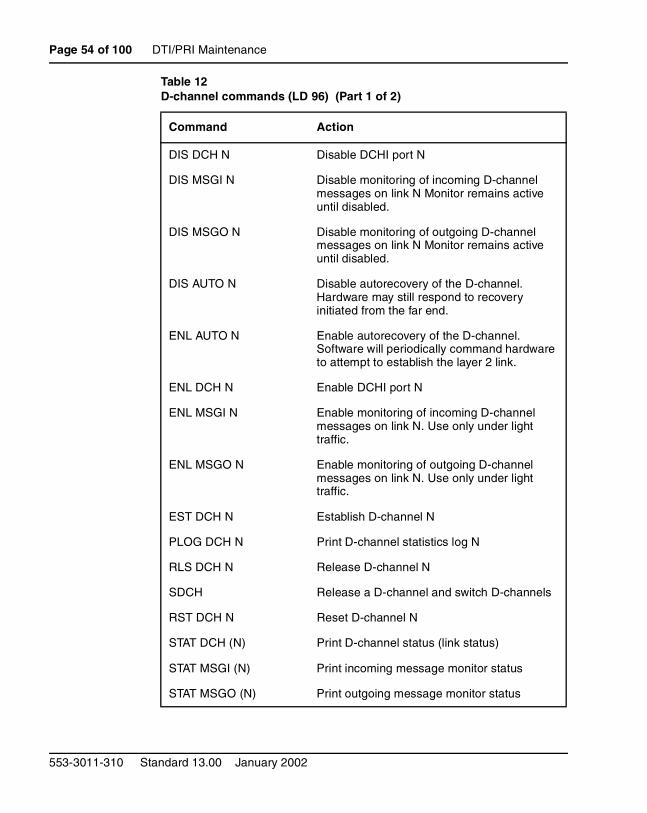
Table 12D-channel commands (LD 96) (Part 1 of 2)
Command Action
DIS DCH N Disable DCHI port N
DIS MSGI N Disable monitoring of incoming D-channel messages on link N Monitor remains active until disabled.
DIS MSGO N Disable monitoring of outgoing D-channel messages on link N Monitor remains active until disabled.
DIS AUTO N Disable autorecovery of the D-channel. Hardware may still respond to recovery initiated from the far end.
ENL AUTO N Enable autorecovery of the D-channel. Software will periodically command hardware to attempt to establish the layer 2 link.
ENL DCH N Enable DCHI port N
ENL MSGI N Enable monitoring of incoming D-channel messages on link N. Use only under light traffic.
ENL MSGO N Enable monitoring of outgoing D-channel messages on link N. Use only under light traffic.
EST DCH N Establish D-channel N
PLOG DCH N Print D-channel statistics log N
RLS DCH N Release D-channel N
SDCH Release a D-channel and switch D-channels
RST DCH N Reset D-channel N
STAT DCH (N) Print D-channel status (link status)
STAT MSGI (N) Print incoming message monitor status
STAT MSGO (N) Print outgoing message monitor status
553-3011-310 Standard 13.00 January 2002
DTI/PRI Maintenance Page 55 of 100
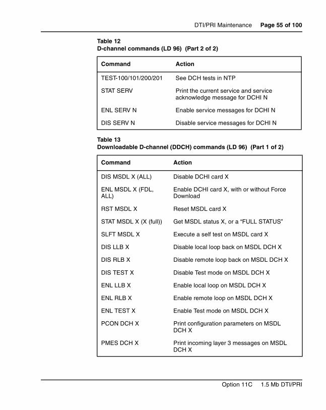
TEST-100/101/200/201 See DCH tests in NTP
STAT SERV Print the current service and service acknowledge message for DCHI N
ENL SERV N Enable service messages for DCHI N
DIS SERV N Disable service messages for DCHI N
Table 13Downloadable D-channel (DDCH) commands (LD 96) (Part 1 of 2)
Command Action
DIS MSDL X (ALL) Disable DCHI card X
ENL MSDL X (FDL, ALL)
Enable DCHI card X, with or without Force Download
RST MSDL X Reset MSDL card X
STAT MSDL X (X (full)) Get MSDL status X, or a “FULL STATUS”
SLFT MSDL X Execute a self test on MSDL card X
DIS LLB X Disable local loop back on MSDL DCH X
DIS RLB X Disable remote loop back on MSDL DCH X
DIS TEST X Disable Test mode on MSDL DCH X
ENL LLB X Enable local loop on MSDL DCH X
ENL RLB X Enable remote loop on MSDL DCH X
ENL TEST X Enable Test mode on MSDL DCH X
PCON DCH X Print configuration parameters on MSDL DCH X
PMES DCH X Print incoming layer 3 messages on MSDL DCH X
Table 12D-channel commands (LD 96) (Part 2 of 2)
Command Action
Option 11C 1.5 Mb DTI/PRI
Page 56 of 100 DTI/PRI Maintenance
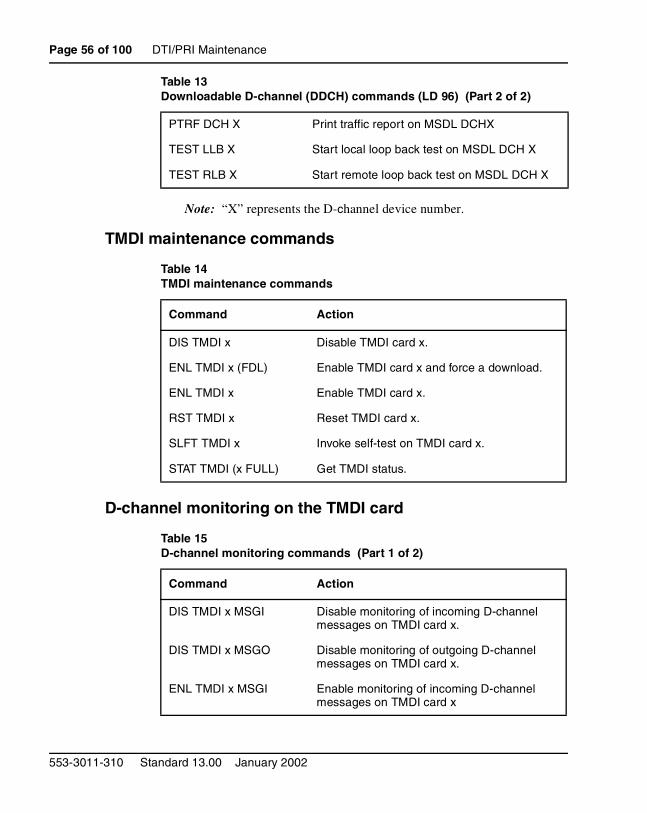
Note: “X” represents the D-channel device number.
TMDI maintenance commands
D-channel monitoring on the TMDI card
PTRF DCH X Print traffic report on MSDL DCHX
TEST LLB X Start local loop back test on MSDL DCH X
TEST RLB X Start remote loop back test on MSDL DCH X
Table 14TMDI maintenance commands
Command Action
DIS TMDI x Disable TMDI card x.
ENL TMDI x (FDL) Enable TMDI card x and force a download.
ENL TMDI x Enable TMDI card x.
RST TMDI x Reset TMDI card x.
SLFT TMDI x Invoke self-test on TMDI card x.
STAT TMDI (x FULL) Get TMDI status.
Table 15D-channel monitoring commands (Part 1 of 2)
Command Action
DIS TMDI x MSGI Disable monitoring of incoming D-channel messages on TMDI card x.
DIS TMDI x MSGO Disable monitoring of outgoing D-channel messages on TMDI card x.
ENL TMDI x MSGI Enable monitoring of incoming D-channel messages on TMDI card x
Table 13Downloadable D-channel (DDCH) commands (LD 96) (Part 2 of 2)
553-3011-310 Standard 13.00 January 2002
DTI/PRI Maintenance Page 57 of 100
D-channel status and error conditions are reported as DCH messages. These messages can be found in the X11 System Messages Guide (553-3001-411).
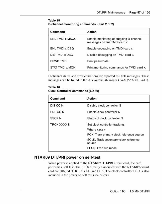
NTAK09 DTI/PRI power on self-testWhen power is applied to the NTAK09 DTI/PRI circuit card, the card performs a self test. The LEDs directly associated with the NTAK09 circuit card are DIS, ACT, RED, YEL, and LBK. The clock controller LED is also included in the power on self test (see below).
ENL TMDI x MSGO Enable monitoring of outgoing D-channel messages on link TMDI card x.
ENL TMDI x DBG Enable debugging on TMDI card x.
DIS TMDI x DBG Disable debugging on TMDI card x.
PSWD TMDI Print passwords.
STAT TMDI x MON Print monitoring commands for TMDI card x.
Table 16Clock Controller commands (LD 60)
Command Action
DIS CC N Disable clock controller N
ENL CC N Enable clock controller N
SSCK N Status of clock controller N
TRCK XXXX N Set clock controller tracking.
Where xxxx =
PCK, Track primary clock reference source
SCLK, Track secondary clock reference source
FRUN, Free run mode
Table 15D-channel monitoring commands (Part 2 of 2)
Command Action
Option 11C 1.5 Mb DTI/PRI
Page 58 of 100 DTI/PRI Maintenance
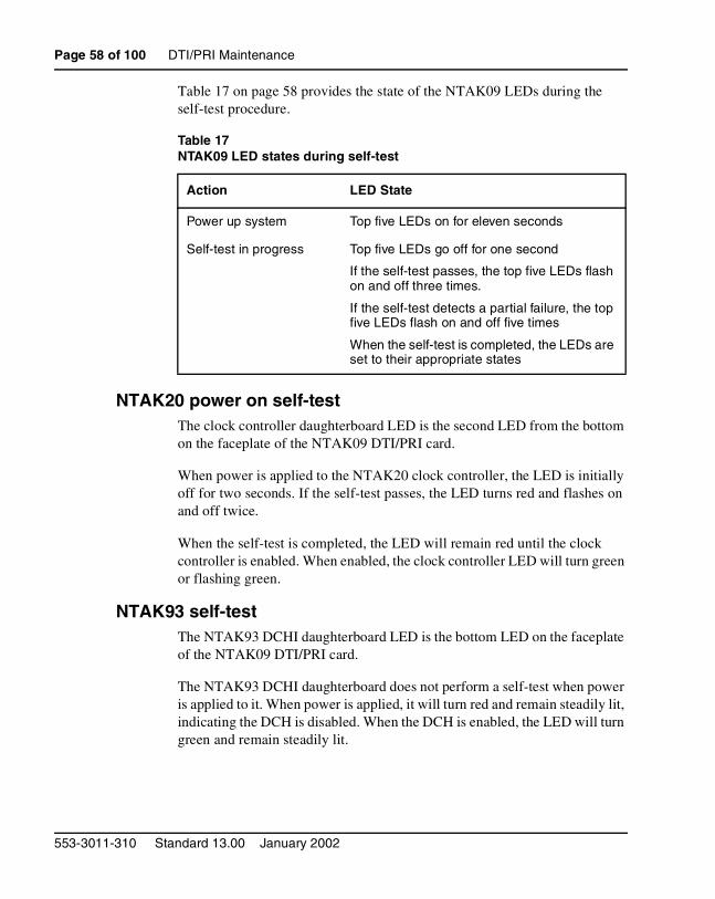
Table 17 on page 58 provides the state of the NTAK09 LEDs during the self-test procedure.
NTAK20 power on self-testThe clock controller daughterboard LED is the second LED from the bottom on the faceplate of the NTAK09 DTI/PRI card.
When power is applied to the NTAK20 clock controller, the LED is initially off for two seconds. If the self-test passes, the LED turns red and flashes on and off twice.
When the self-test is completed, the LED will remain red until the clock controller is enabled. When enabled, the clock controller LED will turn green or flashing green.
NTAK93 self-testThe NTAK93 DCHI daughterboard LED is the bottom LED on the faceplate of the NTAK09 DTI/PRI card.
The NTAK93 DCHI daughterboard does not perform a self-test when power is applied to it. When power is applied, it will turn red and remain steadily lit, indicating the DCH is disabled. When the DCH is enabled, the LED will turn green and remain steadily lit.
Table 17NTAK09 LED states during self-test
Action LED State
Power up system Top five LEDs on for eleven seconds
Self-test in progress Top five LEDs go off for one second
If the self-test passes, the top five LEDs flash on and off three times.
If the self-test detects a partial failure, the top five LEDs flash on and off five times
When the self-test is completed, the LEDs are set to their appropriate states
553-3011-310 Standard 13.00 January 2002
DTI/PRI Maintenance Page 59 of 100
Self-tests of the NTAK93 daughterboard are invoked manually by commands in LD 96.
DTI/PRI local self-test The local self-test, also called a local loopback test, checks speech path continuity, zero code suppression, remote alarm detection, and A and B bit signalling. This test is performed manually on a per-loop (or link- 24 channels) or per-channel basis. The local loopback test performs a local logical loopback and does not require any external loopback of the T-1 signal.
Restrictions and limitationsThe DCHI and DTI/PRI must be disabled before performing the self-test on the entire DTI/PRI card. Individual channels must be disabled before performing a self test on a particular channel.
Self testing the DTI/PRI cardTo perform a self test on the entire DTI/PRI card, do the following:
1 Disable the DCHI using LD 96:
LD 96
DIS DCH N
2 Disable the DTI/PRI card and run the self-test using LD 60:
LD 60
DISL C
SLFT C (entire card)
Self testing individual channelsFollow the same procedure as above, but use the following commands:
DSCH C CH
SLFT C CH (specific channel)
DTI/PRI automatic local loopback testThere are two types of automatic local loopback tests:
• ATLP 0 (disable auto loop test in daily routine — LD 60)
• ATLP 1 (enable auto loop test in daily routine — LD 60)
Option 11C 1.5 Mb DTI/PRI
Page 60 of 100 DTI/PRI Maintenance
The automatic loop test checks the same functions as the manual self test, but runs automatically as part of the midnight routines.
ATLP 0 disables one idle channel at random and performs a single channel self test. This channel cannot be specified — it is selected by software.
ATLP 1 attempts to test the whole DTI/PRI loop. If ATLP 1 finds all channels in the target link idle, it takes the whole link down and tests it. The node where the self test is being performed sends out a Yellow Alarm while the link is down.
Ensure that LD 73 TRSH RALM will not be exceeded at the far end due to automatic running of the loop test. If TRSH RALM (default=3) is exceeded at the far end, trunks will remain out of service.
Remote Loopback and remote self test The remote loopback and the remote self test are performed manually per loop (or per card in Option 11C).
Remote LoopbackThe RLBK C command puts the DTI/PRI into loopback towards the far end so a remote self test can be performed on equipment at the far end.
Note: The DTI/PRI loop (card) being tested must be disabled.
Remote loopback testThe remote self test, also called the external loopback test, checks the integrity of the DTI/PRI through an external T-1 loopback. If the Remote Loopback command (RLBK) is executed at the far end Meridian 1/SL-1 prior to executing the Remote Self test command (RMST) at the near end, the integrity of the DS-1 facility is tested from end to end.
Note: The DTI/PRI channel or loop (card) being tested must be disabled.
ATLP 0 AUTO SELF TEST LOOP DISABLE
ATLP 1 AUTO SELF TEST LOOP ENABLE
553-3011-310 Standard 13.00 January 2002
DTI/PRI Maintenance Page 61 of 100
Coordinate the tests
1 When a technician at the far end requests a remote loopback on the local Meridian 1:
• Disable the DCHI (for PRI DCHL or BCHL) using LD 96:
LD 96
DIS DCH N
• Disable the DTI/PRI card and activate remote loopback mode using LD 60.
LD 60
DISL C
RLBK C
2 To run the remote self test (external loopback test) through a loopback on the far end Meridian 1:
• Call a technician at the far end. Ask for remote loopback mode on the facility that is to be tested.
• When loopback mode at the far end is confirmed, disable the DCHI (for PRI DCHL or BCHL) using LD 96:
LD 96
DIS DCH N
• Disable the DTI/PRI card and run loopback test using LD 60:
LD 60
DISL C
RMST C
Note: The Remote Self test (external loopback test) can be run through any loopback that is external to the DTI/PRI card. The loopback can range from a loopback connector plugged into the NTBK04 cable to a Remote Loopback on the far end DTI/PRI, or at any point in between on the DS-1 facility.
Figure 5 on page 62 shows the relationship between the remote loopback test and the link diagnostic test.
Option 11C 1.5 Mb DTI/PRI
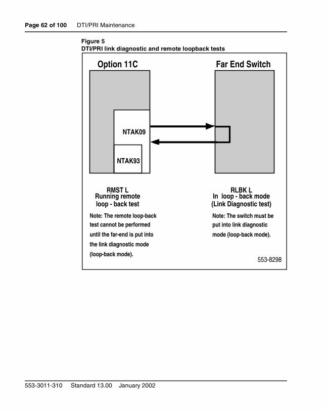
Page 62 of 100 DTI/PRI Maintenance
Figure 5DTI/PRI link diagnostic and remote loopback tests
Option 11C Far End Switch
NTAK93
NTAK09
RMST LRunning remoteloop - back test
RLBK LIn loop - back mode(Link Diagnostic test)
Note: The remote loop-backtest cannot be performed
until the far-end is put into
the link diagnostic mode
(loop-back mode).
Note: The switch must beput into link diagnostic
mode (loop-back mode).
553-8298
553-3011-310 Standard 13.00 January 2002
DTI/PRI Maintenance Page 63 of 100
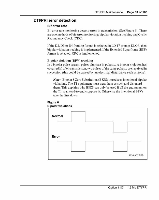
DTI/PRI error detectionBit error rateBit error rate monitoring detects errors in transmission. (See Figure 6). There are two methods of bit error monitoring: bipolar violation tracking and Cyclic Redundancy Check (CRC).
If the D2, D3 or D4 framing format is selected in LD 17 prompt DLOP, then bipolar violation tracking is implemented. If the Extended Superframe (ESF) format is selected, CRC is implemented.
Bipolar violation (BPV) trackingIn a bipolar pulse stream, pulses alternate in polarity. A bipolar violation has occurred if, after transmission, two pulses of the same polarity are received in succession (this could be caused by an electrical disturbance such as noise).
Note: Bipolar 8 Zero Substitution (B8ZS) introduces intentional bipolar violations. The T1 equipment must treat them as such and disregard them. This explains why B8ZS can only be used if all the equipment on the T1 span (end-to-end) supports it. Otherwise the intentional BPVs take the link down.
Figure 6Bipolar violations
553-8300.EPS
Normal
Error
Option 11C 1.5 Mb DTI/PRI
Page 64 of 100 DTI/PRI Maintenance
Cyclic Redundancy CheckThe Extended Superframe Format (ESF) contains a checksum of all data in the frame. The receiving side uses the checksum to verify the data.
The primary difference between BPV and CRC is that bipolar violation tracking indicates errors in the local span, while CRC indicates errors on an end to end span. For example, on a satellite link, BPV only detects errors in the span between the Meridian 1 and the satellite connection. Since CRC traverses the entire span, it indicates an end-to-end bit error rate.
DTI/PRI hardware detects BPV or CRC errors. It sends an overflow (OVFL) message to the Meridian 1 CPU each time 1024 BPV or CRC errors are detected. Running the midnight routines prints the number of overflows and clears the counter.
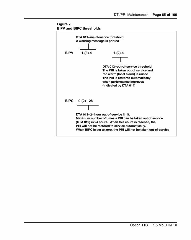
Bit error rate threshold messagesThere are three bit error rate thresholds set in LD 73, using one of two prompts: BIPV or BIPC. When a threshold is reached, a DTA message is produced. (See Figure 7.)
Message Explanation
DTA011 Bit error rate maintenance threshold has been reached.
DTA012 Bit error rate out of service limit has been reached.
DTA013 Too many bit error rate out of service occurrences in the last 24 hours.
553-3011-310 Standard 13.00 January 2002
DTI/PRI Maintenance Page 65 of 100
Figure 7BIPV and BIPC thresholds
BIPV 1-(3)-4 1-(2)-4
BIPC 0-(2)-128
DTA 011--maintenance threshold A warning message is printed
DTA 012--out-of-service threshold The PRI is taken out of service and red alarm (local alarm) is raised. The PRI is restored automatically when performance improves (indicated by DTA 014)
DTA 013--24 hour out-of-service limit. Maximum number of times a PRI can be taken out of service (DTA 012) in 24 hours. When this count is reached, the PRI will not be restored to service automatically. When BIPC is set to zero, the PRI will not be taken out-of-service
Option 11C 1.5 Mb DTI/PRI
Page 66 of 100 DTI/PRI Maintenance
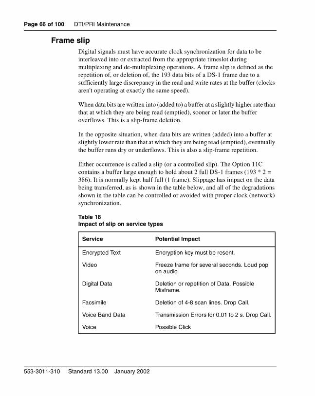
Frame slipDigital signals must have accurate clock synchronization for data to be interleaved into or extracted from the appropriate timeslot during multiplexing and de-multiplexing operations. A frame slip is defined as the repetition of, or deletion of, the 193 data bits of a DS-1 frame due to a sufficiently large discrepancy in the read and write rates at the buffer (clocks aren't operating at exactly the same speed).
When data bits are written into (added to) a buffer at a slightly higher rate than that at which they are being read (emptied), sooner or later the buffer overflows. This is a slip-frame deletion.
In the opposite situation, when data bits are written (added) into a buffer at slightly lower rate than that at which they are being read (emptied), eventually the buffer runs dry or underflows. This is also a slip-frame repetition.
Either occurrence is called a slip (or a controlled slip). The Option 11C contains a buffer large enough to hold about 2 full DS-1 frames (193 * 2 = 386). It is normally kept half full (1 frame). Slippage has impact on the data being transferred, as is shown in the table below, and all of the degradations shown in the table can be controlled or avoided with proper clock (network) synchronization.
Table 18Impact of slip on service types
Service Potential Impact
Encrypted Text Encryption key must be resent.
Video Freeze frame for several seconds. Loud pop on audio.
Digital Data Deletion or repetition of Data. Possible Misframe.
Facsimile Deletion of 4-8 scan lines. Drop Call.
Voice Band Data Transmission Errors for 0.01 to 2 s. Drop Call.
Voice Possible Click
553-3011-310 Standard 13.00 January 2002
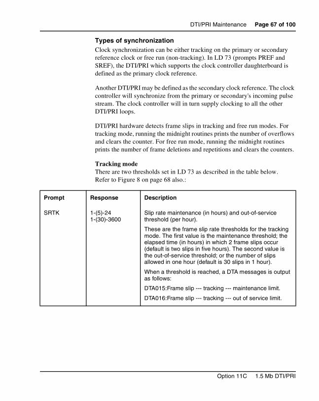
DTI/PRI Maintenance Page 67 of 100
Types of synchronizationClock synchronization can be either tracking on the primary or secondary reference clock or free run (non-tracking). In LD 73 (prompts PREF and SREF), the DTI/PRI which supports the clock controller daughterboard is defined as the primary clock reference.
Another DTI/PRI may be defined as the secondary clock reference. The clock controller will synchronize from the primary or secondary's incoming pulse stream. The clock controller will in turn supply clocking to all the other DTI/PRI loops.
DTI/PRI hardware detects frame slips in tracking and free run modes. For tracking mode, running the midnight routines prints the number of overflows and clears the counter. For free run mode, running the midnight routines prints the number of frame deletions and repetitions and clears the counters.
Tracking modeThere are two thresholds set in LD 73 as described in the table below. Refer to Figure 8 on page 68 also.:
Prompt Response Description
SRTK 1-(5)-24 1-(30)-3600
Slip rate maintenance (in hours) and out-of-service threshold (per hour).
These are the frame slip rate thresholds for the tracking mode. The first value is the maintenance threshold; the elapsed time (in hours) in which 2 frame slips occur (default is two slips in five hours). The second value is the out-of-service threshold; or the number of slips allowed in one hour (default is 30 slips in 1 hour).
When a threshold is reached, a DTA messages is output as follows:
DTA015:Frame slip --- tracking --- maintenance limit.
DTA016:Frame slip --- tracking --- out of service limit.
Option 11C 1.5 Mb DTI/PRI
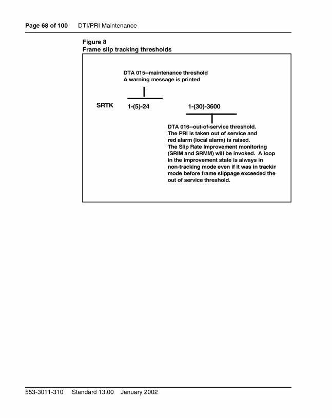
Page 68 of 100 DTI/PRI Maintenance
Figure 8Frame slip tracking thresholds
SRTK 1-(5)-24 1-(30)-3600
DTA 015--maintenance threshold A warning message is printed
DTA 016--out-of-service threshold. The PRI is taken out of service and red alarm (local alarm) is raised. The Slip Rate Improvement monitoring (SRIM and SRMM) will be invoked. A loop in the improvement state is always in non-tracking mode even if it was in trackinmode before frame slippage exceeded the out of service threshold.
553-3011-310 Standard 13.00 January 2002
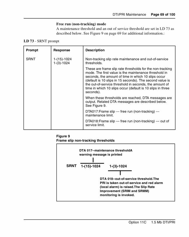
DTI/PRI Maintenance Page 69 of 100
Free run (non-tracking) modeA maintenance threshold and an out of service threshold are set in LD 73 as described below. See Figure 9 on page 69 for additional information.:
Figure 9Frame slip non-tracking thresholds
LD 73 - SRNT prompt
Prompt Response Description
SRNT 1-(15)-1024 1-(3)-1024
Non-tracking slip rate maintenance and out-of-service thresholds.
These are frame slip rate thresholds for the non-tracking mode. The first value is the maintenance threshold in seconds, the amount of time in which 10 slips occur (default is 10 slips in 15 seconds). The second value is the out-of-service threshold in seconds, the amount of time in which 10 slips occur (default is 10 slips in three seconds).
When these thresholds are reached, DTA messages are output. Related DTA messages are described below. See Figure 9.
DTA017:Frame slip --- free run (non-tracking) --- maintenance limit.
DTA018:Frame slip --- free run (non-tracking) --- out of service limit.
SRNT 1-(15)-1024 1-(3)-1024
DTA 017--maintenance thresholdA warning message is printed
DTA 018--out-of-service threshold.The PRI is taken out-of-service and red alarm (local alarm) is raised.The Slip Rate Improvement (SRIM and SRMM) monitoring is invoked.
Option 11C 1.5 Mb DTI/PRI
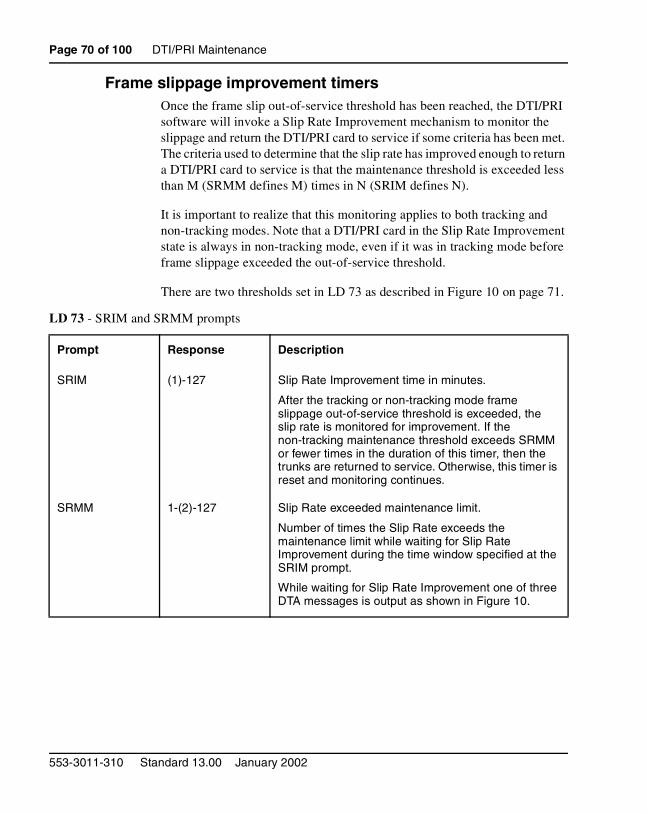
Page 70 of 100 DTI/PRI Maintenance
Frame slippage improvement timersOnce the frame slip out-of-service threshold has been reached, the DTI/PRI software will invoke a Slip Rate Improvement mechanism to monitor the slippage and return the DTI/PRI card to service if some criteria has been met. The criteria used to determine that the slip rate has improved enough to return a DTI/PRI card to service is that the maintenance threshold is exceeded less than M (SRMM defines M) times in N (SRIM defines N).
It is important to realize that this monitoring applies to both tracking and non-tracking modes. Note that a DTI/PRI card in the Slip Rate Improvement state is always in non-tracking mode, even if it was in tracking mode before frame slippage exceeded the out-of-service threshold.
There are two thresholds set in LD 73 as described in Figure 10 on page 71.
LD 73 - SRIM and SRMM prompts
Prompt Response Description
SRIM (1)-127 Slip Rate Improvement time in minutes.
After the tracking or non-tracking mode frame slippage out-of-service threshold is exceeded, the slip rate is monitored for improvement. If the non-tracking maintenance threshold exceeds SRMM or fewer times in the duration of this timer, then the trunks are returned to service. Otherwise, this timer is reset and monitoring continues.
SRMM 1-(2)-127 Slip Rate exceeded maintenance limit.
Number of times the Slip Rate exceeds the maintenance limit while waiting for Slip Rate Improvement during the time window specified at the SRIM prompt.
While waiting for Slip Rate Improvement one of three DTA messages is output as shown in Figure 10.
553-3011-310 Standard 13.00 January 2002
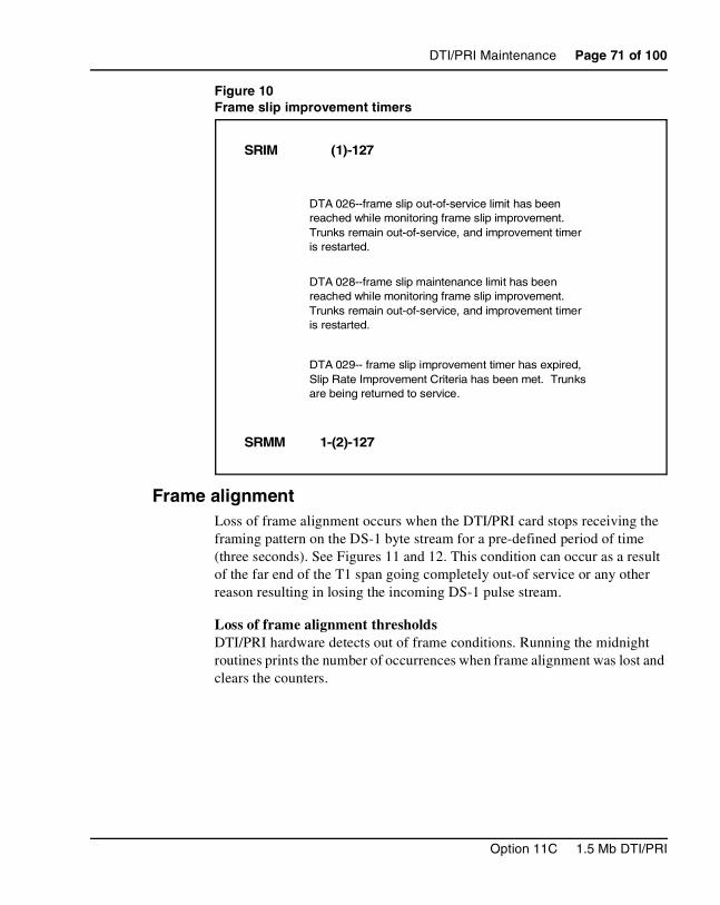
DTI/PRI Maintenance Page 71 of 100
Figure 10Frame slip improvement timers
Frame alignmentLoss of frame alignment occurs when the DTI/PRI card stops receiving the framing pattern on the DS-1 byte stream for a pre-defined period of time (three seconds). See Figures 11 and 12. This condition can occur as a result of the far end of the T1 span going completely out-of service or any other reason resulting in losing the incoming DS-1 pulse stream.
Loss of frame alignment thresholds DTI/PRI hardware detects out of frame conditions. Running the midnight routines prints the number of occurrences when frame alignment was lost and clears the counters.
DTA 029-- frame slip improvement timer has expired, Slip Rate Improvement Criteria has been met. Trunks are being returned to service.
(1)-127 SRIM
SRMM 1-(2)-127
DTA 026--frame slip out-of-service limit has been reached while monitoring frame slip improvement. Trunks remain out-of-service, and improvement timer is restarted.
DTA 028--frame slip maintenance limit has been reached while monitoring frame slip improvement. Trunks remain out-of-service, and improvement timer is restarted.
Option 11C 1.5 Mb DTI/PRI
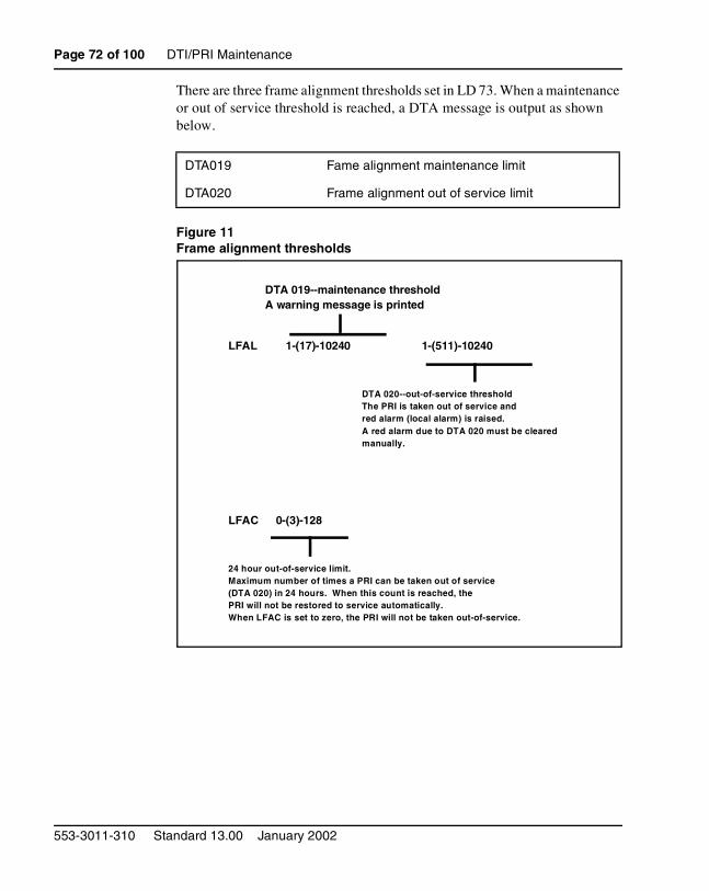
Page 72 of 100 DTI/PRI Maintenance
There are three frame alignment thresholds set in LD 73. When a maintenance or out of service threshold is reached, a DTA message is output as shown below.
Figure 11Frame alignment thresholds
DTA019 Fame alignment maintenance limit
DTA020 Frame alignment out of service limit
LFAL 1-(17)-10240 1-(511)-10240
LFAC 0-(3)-128
DTA 019--maintenance threshold A warning message is printed
DTA 020--out-of-service threshold The PRI is taken out of service and red alarm (local alarm) is raised. A red alarm due to DTA 020 must be cleared manually.
24 hour out-of-service limit. Maximum number of times a PRI can be taken out of service (DTA 020) in 24 hours. When this count is reached, the PRI will not be restored to service automatically. When LFAC is set to zero, the PRI will not be taken out-of-service.
553-3011-310 Standard 13.00 January 2002
DTI/PRI Maintenance Page 73 of 100
If a loss of frame alignment condition persists for three seconds, the affected DTI/PRI card is taken out of service and a red alarm (local alarm) is raised. See Figure 12.
If the loss of frame alignment condition clears at least 15 seconds, the DTI/PRI is automatically restored to service. The following DTA message is generated:
Figure 12Loss of frame alignment
Alarm threshold recommendations for digital trunksIf a digital trunk is present in an IP Expansion cabinet, link outages due to data network performance degradation between main cabinet and expansion cabinet will cause alarms on the far end of the digital trunk. If link outages are frequent, alarm thresholds on the far end may need to be increased to prevent the trunk from being placed in a state requiring manual intervention to recover.
Clock operationThe Option 11C system supports a single clock controller that can operate in one of two modes: tracking or non-tracking (also known as free-run).
DTA021 Loss of frame alignment has persisted for 3 seconds.
DTA 021--loss of frame alignment.
DTA 022--loss of frame alignment cleared
3 seconds
15 seconds
Option 11C 1.5 Mb DTI/PRI
Page 74 of 100 DTI/PRI Maintenance
Tracking modeIn tracking mode, one or possibly two DTI/PRI cards supply a clock reference to a clock controller daughterboard. When operating in tracking mode, one DTI/PRI is defined as the primary reference source for clock synchronization, while the other is defined as the secondary reference source (PREF and SREF in LD 73).
There are two stages to clock controller tracking:
• tracking a reference, and
• locked onto a reference.
When tracking a reference, the clock controller uses an algorithm to match its frequency to the frequency of the incoming clock. When the frequencies are very near to being matched, the clock controller is locked onto the reference. The clock controller will make small adjustments to its own frequency until both the incoming and system frequencies correspond.
If the incoming clock reference is stable, the internal clock controller will track it, lock onto it, and match frequencies exactly. Occasionally, however, environmental circumstances will cause the external or internal clocks to drift. When this happens, the internal clock controller will briefly enter the tracking stage. The green LED will flash momentarily until the clock controller is locked onto the reference once again.
If the incoming reference is unstable, the internal clock controller will continuously be in the tracking stage, with the LED flashing green all the time. This condition does not present a problem, rather, it shows that the clock controller is continually attempting to lock onto the signal. If slips are occurring, however, it means that there is a problem with the clock controller or the incoming line.
Free-run (non-tracking)In free-run mode, the clock controller does not synchronize on any source, it provides its own internal clock to the system. This mode can be used when the Meridian 1 is used as a master clock source for other systems in the network. Free-run mode is undesirable if the Meridian 1 is intended to be a slave. It can occur, however, when both the primary and secondary clock sources are lost due to hardware faults or when invoked by using software commands.
553-3011-310 Standard 13.00 January 2002
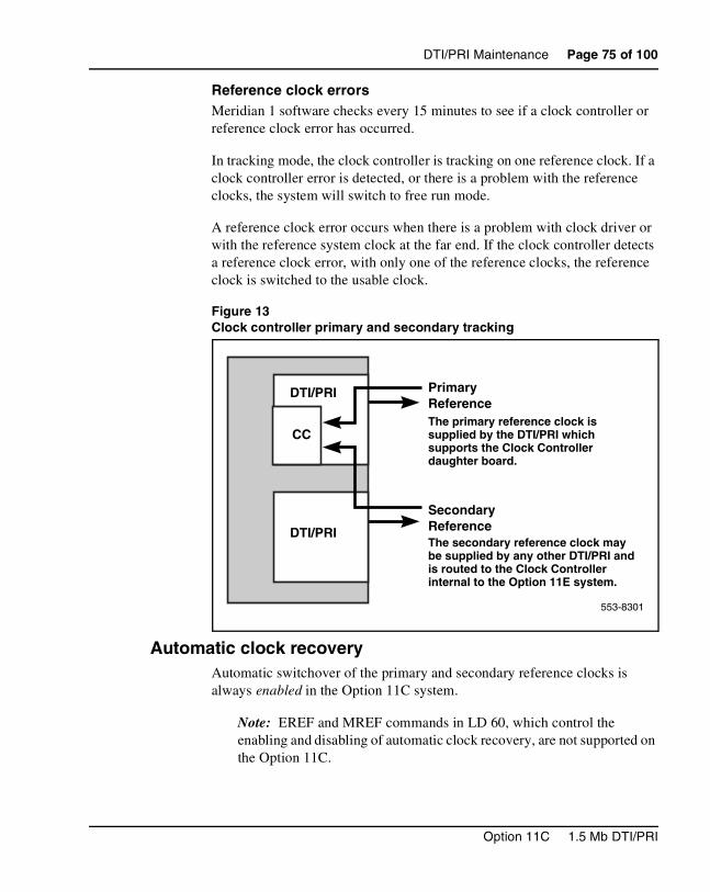
DTI/PRI Maintenance Page 75 of 100
Reference clock errorsMeridian 1 software checks every 15 minutes to see if a clock controller or reference clock error has occurred.
In tracking mode, the clock controller is tracking on one reference clock. If a clock controller error is detected, or there is a problem with the reference clocks, the system will switch to free run mode.
A reference clock error occurs when there is a problem with clock driver or with the reference system clock at the far end. If the clock controller detects a reference clock error, with only one of the reference clocks, the reference clock is switched to the usable clock.
Figure 13Clock controller primary and secondary tracking
Automatic clock recoveryAutomatic switchover of the primary and secondary reference clocks is always enabled in the Option 11C system.
Note: EREF and MREF commands in LD 60, which control the enabling and disabling of automatic clock recovery, are not supported on the Option 11C.
553-8301
DTI/PRI
DTI/PRI
CC
PrimaryReferenceThe primary reference clock is supplied by the DTI/PRI which supports the Clock Controller daughter board.
SecondaryReferenceThe secondary reference clock may be supplied by any other DTI/PRI and is routed to the Clock Controller internal to the Option 11E system.
Option 11C 1.5 Mb DTI/PRI
Page 76 of 100 DTI/PRI Maintenance
Replace equipmentUse the following procedure before you reseat the NTAK09, the NTAK20 and/or the NTAK93:
1 If the NTAK93 DCHI daughterboard is installed, first S/W disable the associated D-channel (DCHI) using the following overlay and commands:
LD 96 DIS DCH
Where X is the DCHI port number that was assigned in LD17.
2 If the NTAK20 Clock Controller daughterboard is installed, first S/W disable it using the following overlay and commands:
LD 60 DIS CC 0
(Where CC is the card slot number of the NTAK09 that was supporting the NTAK20 Clock Controller).
3 S/W disable the DTI/PRI card as follows:
LD 60 DISL X
(Where X is the card slot number of the NTAK09 DTI/PRI).
4 To replace the NTAK09 by the lock latches, unlock the latches and slide the card out of the cabinet. Once out of the slot you may remove any of the daughterboards.
Note: To avoid damage to the circuit cards from electrostatic discharge, wear the wrist strap connected to the inside of your Option 11C cabinet whenever handling the circuit cards. Figure 14 shows the connection point for the wrist strap.
553-3011-310 Standard 13.00 January 2002
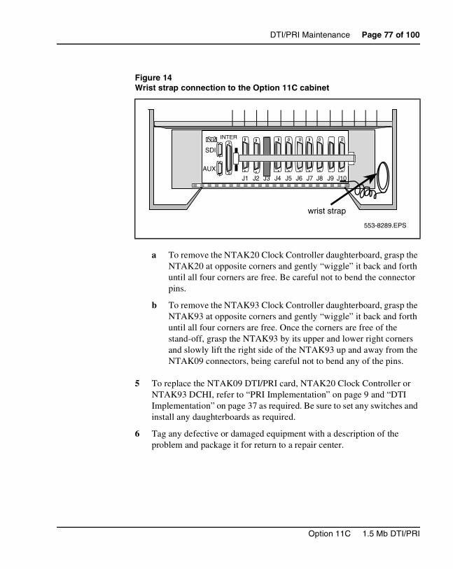
DTI/PRI Maintenance Page 77 of 100
a To remove the NTAK20 Clock Controller daughterboard, grasp the NTAK20 at opposite corners and gently “wiggle” it back and forth until all four corners are free. Be careful not to bend the connector pins.
b To remove the NTAK93 Clock Controller daughterboard, grasp the NTAK93 at opposite corners and gently “wiggle” it back and forth until all four corners are free. Once the corners are free of the stand-off, grasp the NTAK93 by its upper and lower right corners and slowly lift the right side of the NTAK93 up and away from the NTAK09 connectors, being careful not to bend any of the pins.
5 To replace the NTAK09 DTI/PRI card, NTAK20 Clock Controller or NTAK93 DCHI, refer to “PRI Implementation” on page 9 and “DTI Implementation” on page 37 as required. Be sure to set any switches and install any daughterboards as required.
6 Tag any defective or damaged equipment with a description of the problem and package it for return to a repair center.
Figure 14Wrist strap connection to the Option 11C cabinet
wrist strap
J3
INTER
J1 J2 J4 J5 J6 J7 J8 J9 J10
SDI
AUX
553-8289.EPS
Option 11C 1.5 Mb DTI/PRI
Page 78 of 100 DTI/PRI Maintenance
553-3011-310 Standard 13.00 January 2002
Page 79 of 100
92
ISL ImplementationContents
This section contains information on the following topics:
Reference list . . . . . . . . . . . . . . . . . . . . . . . . . . . . . . . . . . . . . . . . . . . . . 79
Overview . . . . . . . . . . . . . . . . . . . . . . . . . . . . . . . . . . . . . . . . . . . . . . . . 80
Hardware Requirements . . . . . . . . . . . . . . . . . . . . . . . . . . . . . . . . . . . . . 80
Shared Mode . . . . . . . . . . . . . . . . . . . . . . . . . . . . . . . . . . . . . . . . . . . . . 80
Dedicated Mode . . . . . . . . . . . . . . . . . . . . . . . . . . . . . . . . . . . . . . . . . . . 80
Restrictions and limitations . . . . . . . . . . . . . . . . . . . . . . . . . . . . . . . . . . 83
Installation procedure . . . . . . . . . . . . . . . . . . . . . . . . . . . . . . . . . . . . . . . 83
Software Programming . . . . . . . . . . . . . . . . . . . . . . . . . . . . . . . . . . . . . 85
Program Dedicated mode . . . . . . . . . . . . . . . . . . . . . . . . . . . . . . . . . . . . 85
Program Shared mode . . . . . . . . . . . . . . . . . . . . . . . . . . . . . . . . . . . . . . 91
Reference listThe following are the references in this section:
• X11 System Messages Guide (553-3001-411)
Option 11C 1.5 Mb DTI/PRI
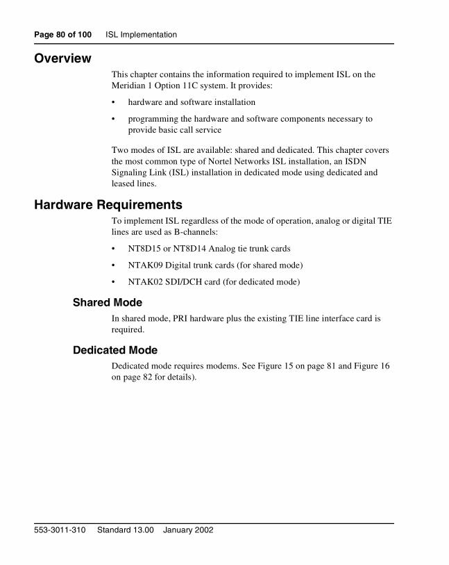
Page 80 of 100 ISL Implementation
OverviewThis chapter contains the information required to implement ISL on the Meridian 1 Option 11C system. It provides:
• hardware and software installation
• programming the hardware and software components necessary to provide basic call service
Two modes of ISL are available: shared and dedicated. This chapter covers the most common type of Nortel Networks ISL installation, an ISDN Signaling Link (ISL) installation in dedicated mode using dedicated and leased lines.
Hardware RequirementsTo implement ISL regardless of the mode of operation, analog or digital TIE lines are used as B-channels:
• NT8D15 or NT8D14 Analog tie trunk cards
• NTAK09 Digital trunk cards (for shared mode)
• NTAK02 SDI/DCH card (for dedicated mode)
Shared ModeIn shared mode, PRI hardware plus the existing TIE line interface card is required.
Dedicated ModeDedicated mode requires modems. See Figure 15 on page 81 and Figure 16 on page 82 for details).
553-3011-310 Standard 13.00 January 2002
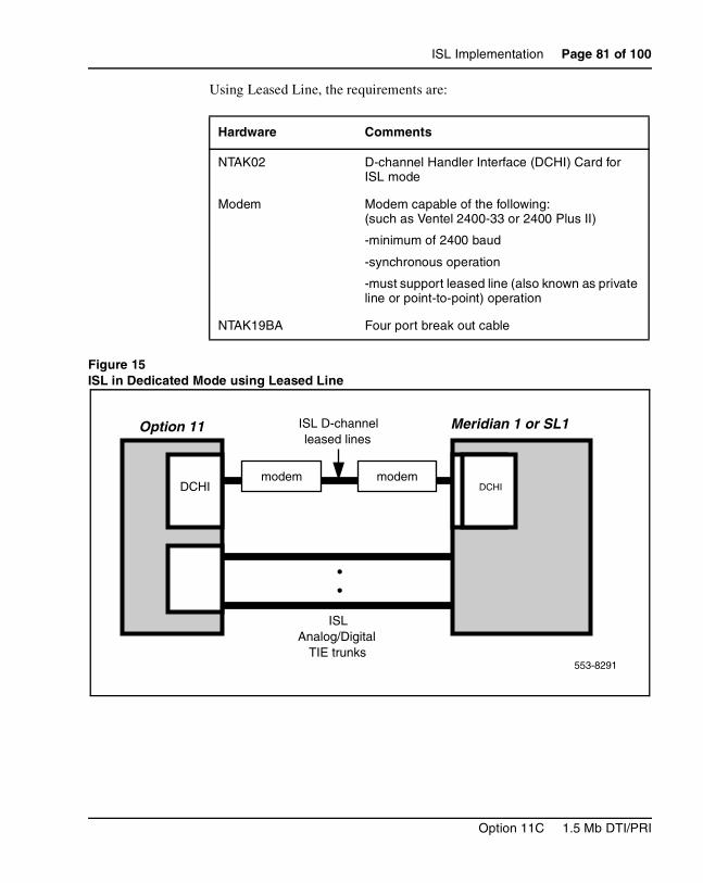
ISL Implementation Page 81 of 100
Using Leased Line, the requirements are:
Figure 15ISL in Dedicated Mode using Leased Line
Hardware Comments
NTAK02 D-channel Handler Interface (DCHI) Card for ISL mode
Modem Modem capable of the following: (such as Ventel 2400-33 or 2400 Plus II)
-minimum of 2400 baud
-synchronous operation
-must support leased line (also known as private line or point-to-point) operation
NTAK19BA Four port break out cable
Option 11 Meridian 1 or SL1ISL D-channel leased lines
ISL Analog/Digital
TIE trunks
••
DCHI DCHIDCHImodem modem
553-8291
Option 11C 1.5 Mb DTI/PRI
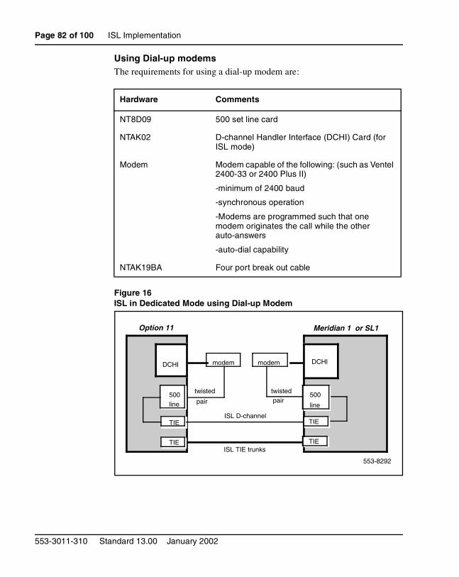
Page 82 of 100 ISL Implementation
Using Dial-up modemsThe requirements for using a dial-up modem are:
Figure 16ISL in Dedicated Mode using Dial-up Modem
Hardware Comments
NT8D09 500 set line card
NTAK02 D-channel Handler Interface (DCHI) Card (for ISL mode)
Modem Modem capable of the following: (such as Ventel 2400-33 or 2400 Plus II)
-minimum of 2400 baud
-synchronous operation
-Modems are programmed such that one modem originates the call while the other auto-answers
-auto-dial capability
NTAK19BA Four port break out cable
Option 11
DCHI
Meridian 1 or SL1
DCHI
ISL D-channel
modem
ISL TIE trunksTIE
twisted
pair
TIE
TIE
modem
twisted pair
500
line
TIE
500 line
553-8292
553-3011-310 Standard 13.00 January 2002
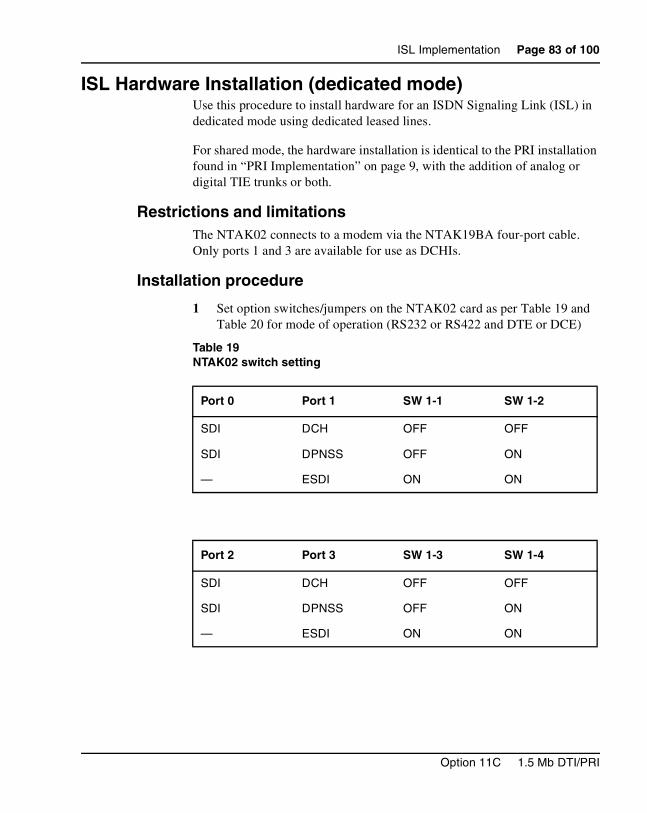
ISL Implementation Page 83 of 100
ISL Hardware Installation (dedicated mode)Use this procedure to install hardware for an ISDN Signaling Link (ISL) in dedicated mode using dedicated leased lines.
For shared mode, the hardware installation is identical to the PRI installation found in “PRI Implementation” on page 9, with the addition of analog or digital TIE trunks or both.
Restrictions and limitationsThe NTAK02 connects to a modem via the NTAK19BA four-port cable. Only ports 1 and 3 are available for use as DCHIs.
Installation procedure
1 Set option switches/jumpers on the NTAK02 card as per Table 19 and Table 20 for mode of operation (RS232 or RS422 and DTE or DCE)
Table 19NTAK02 switch setting
Port 0 Port 1 SW 1-1 SW 1-2
SDI DCH OFF OFF
SDI DPNSS OFF ON
— ESDI ON ON
Port 2 Port 3 SW 1-3 SW 1-4
SDI DCH OFF OFF
SDI DPNSS OFF ON
— ESDI ON ON
Option 11C 1.5 Mb DTI/PRI
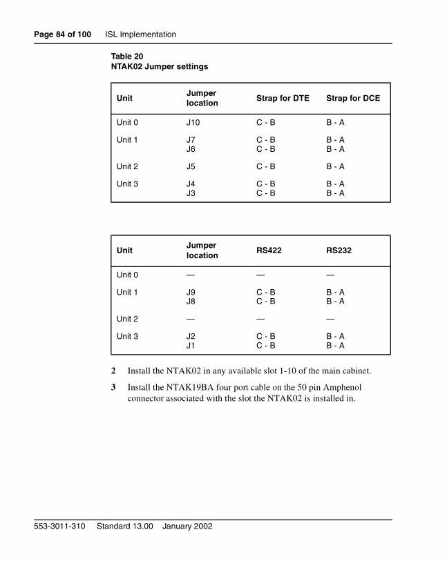
Page 84 of 100 ISL Implementation
Table 20NTAK02 Jumper settings
2 Install the NTAK02 in any available slot 1-10 of the main cabinet.
3 Install the NTAK19BA four port cable on the 50 pin Amphenol connector associated with the slot the NTAK02 is installed in.
UnitJumper location Strap for DTE Strap for DCE
Unit 0 J10 C - B B - A
Unit 1 J7J6
C - BC - B
B - AB - A
Unit 2 J5 C - B B - A
Unit 3 J4J3
C - BC - B
B - AB - A
UnitJumperlocation
RS422 RS232
Unit 0 — — —
Unit 1 J9J8
C - BC - B
B - AB - A
Unit 2 — — —
Unit 3 J2J1
C - BC - B
B - AB - A
553-3011-310 Standard 13.00 January 2002
ISL Implementation Page 85 of 100
4 If the installation is a dedicated mode using leased line modem configuration, the D-channel connects the DCHI with the far-end modem over a dedicated leased line. The modems must have a minimum transmission rate of 2400 baud and must support leased line capability and synchronous mode, 2-wire or 4-wire operation.
Modems such as Ventel 2400 Plus II may be used. You must specify 4-wire operation when ordering, otherwise the modem is factory shipped for 2-wire operation.
Note: The Hayes Smart modem 2400 cannot be used on leased lines.
5 If the installation is a dedicated mode using dial-up modem (such as Hayes 2400, Ventel 2400 or Gandalf 2400) configuration, the DCHI is connected to a modem that is connected to a 500 set line card. The call is connected to the far-end via the 500 set-to-TIE trunk path.
Note: Dedicated mode using leased line modems is the preferred method.
6 Set up the D-channel. Program the modem at one end in the auto-dial mode, so it will automatically initiate a call to the other end at power up. The auto-dial number must be coordinated with the far end switch. The originating modem will have this auto-dial number stored internally as part of the modem configuration routine. The far-end modem needs only to be set-up for auto-answer.
Software Programming
Program Dedicated modeUse this procedure to configure basic ISL capability.
The following programming applies to analog TIE trunks being used as B-channels. When DTI/PRI trunks are also used, LD17 digital loop (DLOP) and LD73 (digital data block-DDB) must also be configured with the appropriate clocking and threshold settings.
Option 11C 1.5 Mb DTI/PRI

Page 86 of 100 ISL Implementation
Restrictions and limitationsThe DCHI in this case uses the NTAK02 circuit card and does not support ISDN PRI signaling. The DCHI is reserved for ISL use only. The D-channel can communicate with the far end by means of a dedicated leased line modem or dial-up modem.
For ISL dedicated mode using a dial-up modem, a 500 set, TIE trunk route and member will have to be programmed (used for D-channel).
Programming procedureProgramming dedicated mode involves four major steps:
1 Configure the D-channel for ISL — use LD 17
2 Enable ISDN option — use LD 15.
3 Enable the ISL option on a per route basis, assigning a D-channel for each route — use LD 16.
4 Assign a channel identification to each trunk with the ISL option — use LD 14.
LD 17 – Configure the D-channel for ISL.
Prompt Response Description
REQ NEWCHG
Add new dataChange existing data
TYPE CFN Configuration data block
ADAN NEW DCH 0-79
Add primary D-channel
CTYP DCHI D-channel card type
CDNO 1-9, 11-19, 21-29, 31-39, 41-49
Card slot in which the card supporting the DCHI resides
PORT 1 Must be set to 1
USR PRI D-channel for ISDN PRI only
IFC SL1 Interface type
553-3011-310 Standard 13.00 January 2002
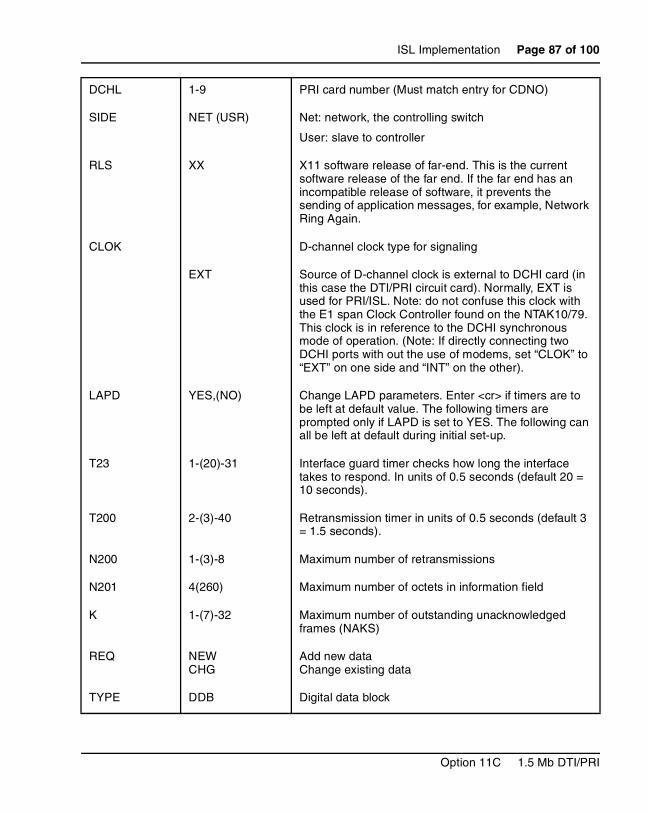
ISL Implementation Page 87 of 100
DCHL 1-9 PRI card number (Must match entry for CDNO)
SIDE NET (USR) Net: network, the controlling switch
User: slave to controller
RLS XX X11 software release of far-end. This is the current software release of the far end. If the far end has an incompatible release of software, it prevents the sending of application messages, for example, Network Ring Again.
CLOK D-channel clock type for signaling
EXT Source of D-channel clock is external to DCHI card (in this case the DTI/PRI circuit card). Normally, EXT is used for PRI/ISL. Note: do not confuse this clock with the E1 span Clock Controller found on the NTAK10/79. This clock is in reference to the DCHI synchronous mode of operation. (Note: If directly connecting two DCHI ports with out the use of modems, set “CLOK” to “EXT” on one side and “INT” on the other).
LAPD YES,(NO) Change LAPD parameters. Enter <cr> if timers are to be left at default value. The following timers are prompted only if LAPD is set to YES. The following can all be left at default during initial set-up.
T23 1-(20)-31 Interface guard timer checks how long the interface takes to respond. In units of 0.5 seconds (default 20 = 10 seconds).
T200 2-(3)-40 Retransmission timer in units of 0.5 seconds (default 3 = 1.5 seconds).
N200 1-(3)-8 Maximum number of retransmissions
N201 4(260) Maximum number of octets in information field
K 1-(7)-32 Maximum number of outstanding unacknowledged frames (NAKS)
REQ NEWCHG
Add new dataChange existing data
TYPE DDB Digital data block
Option 11C 1.5 Mb DTI/PRI
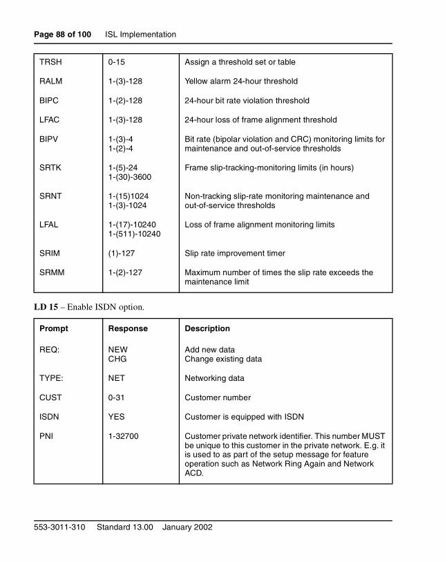
Page 88 of 100 ISL Implementation
LD 15 – Enable ISDN option.
TRSH 0-15 Assign a threshold set or table
RALM 1-(3)-128 Yellow alarm 24-hour threshold
BIPC 1-(2)-128 24-hour bit rate violation threshold
LFAC 1-(3)-128 24-hour loss of frame alignment threshold
BIPV 1-(3)-4 1-(2)-4
Bit rate (bipolar violation and CRC) monitoring limits for maintenance and out-of-service thresholds
SRTK 1-(5)-24 1-(30)-3600
Frame slip-tracking-monitoring limits (in hours)
SRNT 1-(15)10241-(3)-1024
Non-tracking slip-rate monitoring maintenance and out-of-service thresholds
LFAL 1-(17)-102401-(511)-10240
Loss of frame alignment monitoring limits
SRIM (1)-127 Slip rate improvement timer
SRMM 1-(2)-127 Maximum number of times the slip rate exceeds the maintenance limit
Prompt Response Description
REQ: NEWCHG
Add new dataChange existing data
TYPE: NET Networking data
CUST 0-31 Customer number
ISDN YES Customer is equipped with ISDN
PNI 1-32700 Customer private network identifier. This number MUST be unique to this customer in the private network. E.g. it is used to as part of the setup message for feature operation such as Network Ring Again and Network ACD.
553-3011-310 Standard 13.00 January 2002
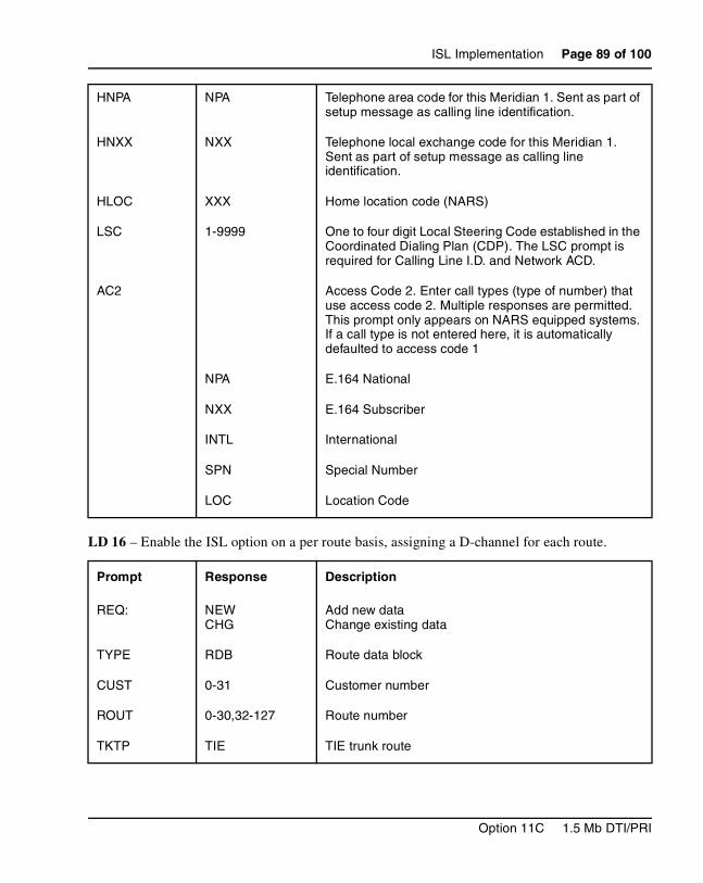
ISL Implementation Page 89 of 100
LD 16 – Enable the ISL option on a per route basis, assigning a D-channel for each route.
HNPA NPA Telephone area code for this Meridian 1. Sent as part of setup message as calling line identification.
HNXX NXX Telephone local exchange code for this Meridian 1. Sent as part of setup message as calling line identification.
HLOC XXX Home location code (NARS)
LSC 1-9999 One to four digit Local Steering Code established in the Coordinated Dialing Plan (CDP). The LSC prompt is required for Calling Line I.D. and Network ACD.
AC2 Access Code 2. Enter call types (type of number) that use access code 2. Multiple responses are permitted. This prompt only appears on NARS equipped systems. If a call type is not entered here, it is automatically defaulted to access code 1
NPA E.164 National
NXX E.164 Subscriber
INTL International
SPN Special Number
LOC Location Code
Prompt Response Description
REQ: NEWCHG
Add new dataChange existing data
TYPE RDB Route data block
CUST 0-31 Customer number
ROUT 0-30,32-127 Route number
TKTP TIE TIE trunk route
Option 11C 1.5 Mb DTI/PRI
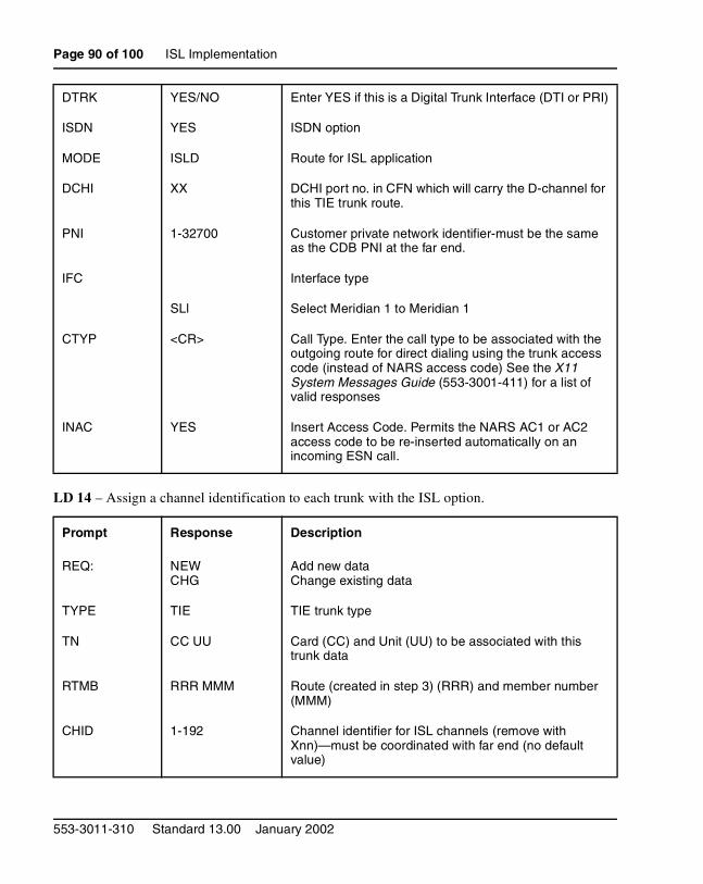
Page 90 of 100 ISL Implementation
LD 14 – Assign a channel identification to each trunk with the ISL option.
DTRK YES/NO Enter YES if this is a Digital Trunk Interface (DTI or PRI)
ISDN YES ISDN option
MODE ISLD Route for ISL application
DCHI XX DCHI port no. in CFN which will carry the D-channel for this TIE trunk route.
PNI 1-32700 Customer private network identifier-must be the same as the CDB PNI at the far end.
IFC Interface type
SLl Select Meridian 1 to Meridian 1
CTYP <CR> Call Type. Enter the call type to be associated with the outgoing route for direct dialing using the trunk access code (instead of NARS access code) See the X11 System Messages Guide (553-3001-411) for a list of valid responses
INAC YES Insert Access Code. Permits the NARS AC1 or AC2 access code to be re-inserted automatically on an incoming ESN call.
Prompt Response Description
REQ: NEWCHG
Add new dataChange existing data
TYPE TIE TIE trunk type
TN CC UU Card (CC) and Unit (UU) to be associated with this trunk data
RTMB RRR MMM Route (created in step 3) (RRR) and member number (MMM)
CHID 1-192 Channel identifier for ISL channels (remove with Xnn)—must be coordinated with far end (no default value)
553-3011-310 Standard 13.00 January 2002
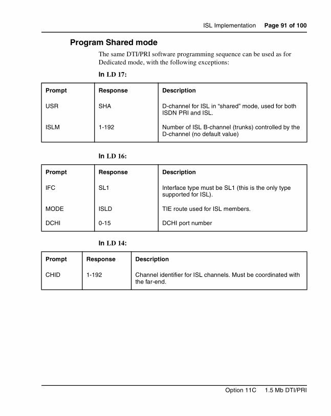
ISL Implementation Page 91 of 100
Program Shared modeThe same DTI/PRI software programming sequence can be used as for Dedicated mode, with the following exceptions:
In LD 17:
In LD 16:
In LD 14:
Prompt Response Description
USR SHA D-channel for ISL in “shared” mode, used for both ISDN PRI and ISL.
ISLM 1-192 Number of ISL B-channel (trunks) controlled by the D-channel (no default value)
Prompt Response Description
IFC SL1 Interface type must be SL1 (this is the only type supported for ISL).
MODE ISLD TIE route used for ISL members.
DCHI 0-15 DCHI port number
Prompt Response Description
CHID 1-192 Channel identifier for ISL channels. Must be coordinated with the far-end.
Option 11C 1.5 Mb DTI/PRI

Page 92 of 100 ISL Implementation
553-3011-310 Standard 13.00 January 2002
Page 93 of 100
100
ISL MaintenanceContents
This section contains information on the following topics:
Reference list . . . . . . . . . . . . . . . . . . . . . . . . . . . . . . . . . . . . . . . . . . . . . 93
Maintenance overview . . . . . . . . . . . . . . . . . . . . . . . . . . . . . . . . . . . . . . 93
Maintenance messages . . . . . . . . . . . . . . . . . . . . . . . . . . . . . . . . . . . . . . 94
Option 11C ISL maintenance tools . . . . . . . . . . . . . . . . . . . . . . . . . . . . 98
Maintenance commands . . . . . . . . . . . . . . . . . . . . . . . . . . . . . . . . . . . . . 98
Maintenance messages . . . . . . . . . . . . . . . . . . . . . . . . . . . . . . . . . . . . . . 99
Maintenance testing . . . . . . . . . . . . . . . . . . . . . . . . . . . . . . . . . . . . . . . . 99
Reference listThe following are the references in this section:
• X11 System Messages Guide (553-3001-411)
Maintenance overviewFrom a maintenance perspective, Option 11C ISL operation consists of these major aspects:
• hardware and software states
• near-end and far-end status
• link and/or span integrity
Option 11C ISL operation is monitored and reported on through service messages.
Option 11C 1.5 Mb DTI/PRI
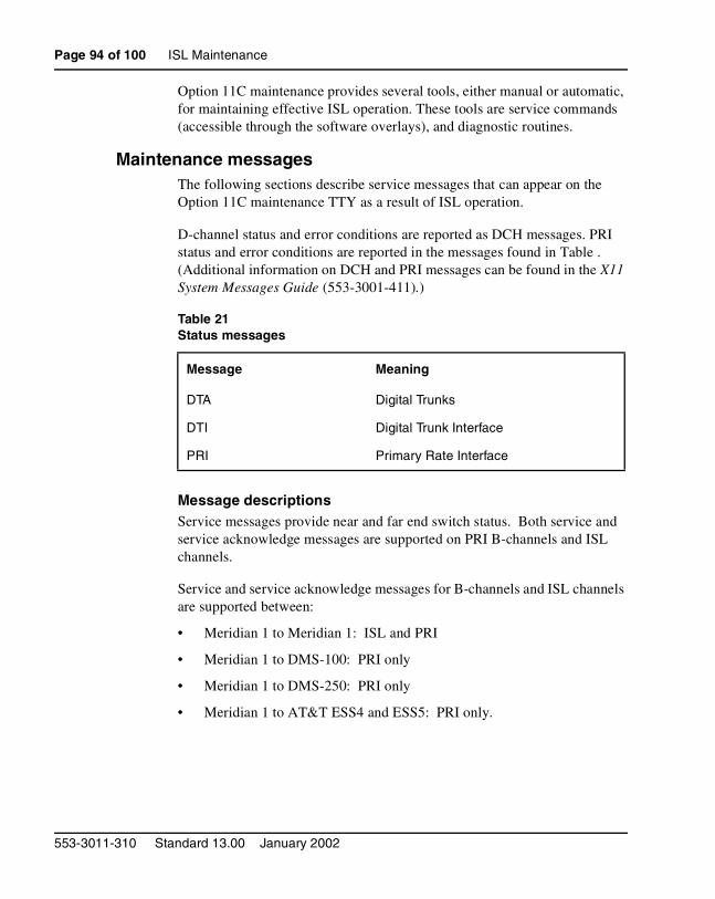
Page 94 of 100 ISL Maintenance
Option 11C maintenance provides several tools, either manual or automatic, for maintaining effective ISL operation. These tools are service commands (accessible through the software overlays), and diagnostic routines.
Maintenance messagesThe following sections describe service messages that can appear on the Option 11C maintenance TTY as a result of ISL operation.
D-channel status and error conditions are reported as DCH messages. PRI status and error conditions are reported in the messages found in Table . (Additional information on DCH and PRI messages can be found in the X11 System Messages Guide (553-3001-411).)
Message descriptionsService messages provide near and far end switch status. Both service and service acknowledge messages are supported on PRI B-channels and ISL channels.
Service and service acknowledge messages for B-channels and ISL channels are supported between:
• Meridian 1 to Meridian 1: ISL and PRI
• Meridian 1 to DMS-100: PRI only
• Meridian 1 to DMS-250: PRI only
• Meridian 1 to AT&T ESS4 and ESS5: PRI only.
Table 21Status messages
Message Meaning
DTA Digital Trunks
DTI Digital Trunk Interface
PRI Primary Rate Interface
553-3011-310 Standard 13.00 January 2002
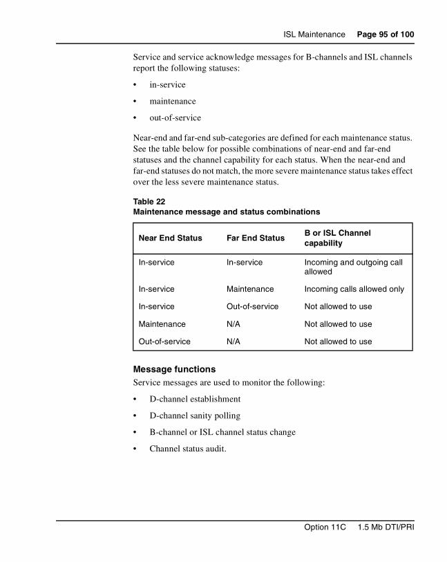
ISL Maintenance Page 95 of 100
Service and service acknowledge messages for B-channels and ISL channels report the following statuses:
• in-service
• maintenance
• out-of-service
Near-end and far-end sub-categories are defined for each maintenance status. See the table below for possible combinations of near-end and far-end statuses and the channel capability for each status. When the near-end and far-end statuses do not match, the more severe maintenance status takes effect over the less severe maintenance status.
Message functionsService messages are used to monitor the following:
• D-channel establishment
• D-channel sanity polling
• B-channel or ISL channel status change
• Channel status audit.
Table 22Maintenance message and status combinations
Near End Status Far End StatusB or ISL Channel capability
In-service In-service Incoming and outgoing call allowed
In-service Maintenance Incoming calls allowed only
In-service Out-of-service Not allowed to use
Maintenance N/A Not allowed to use
Out-of-service N/A Not allowed to use
Option 11C 1.5 Mb DTI/PRI
Page 96 of 100 ISL Maintenance
D-channel establishmentWhen the D-channel establishes, the B-channel status is supported by sending service messages for each B-channel controlled by a D-channel. This allows the far end to synchronize its channel states. These services messages are sent when the D-channel is brought up automatically by the system or manually by using LD 96.
D-channel sanity pollingIf a D-channel has been idle for 30 seconds, a service message is sent to poll the sanity of the link. The service message is sent regardless of whether the near end is configured as master or slave.
B-channel or ISL channel status changeWhenever there is a status change for a B-channel or an ISL channel, the new status is reported to the far end via a service message. Status change can occur through service change or maintenance operations, such as the addition or deletion of a channel in LD 14, or disabling of the associated loop, shelf, card or unit in LD 30, LD 32, LD 36, LD 41 or LD 60.
Channel status auditLD 30 is enhanced to allow channel status audit to be initiated. The channels associated with each D-channel are examined and their status is reported to the far end via service messages.
553-3011-310 Standard 13.00 January 2002
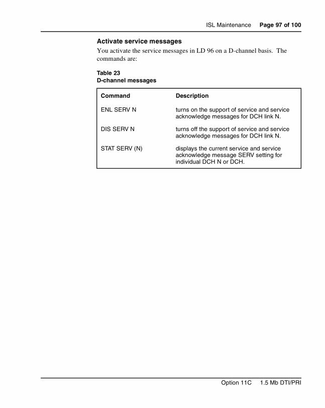
ISL Maintenance Page 97 of 100
Activate service messagesYou activate the service messages in LD 96 on a D-channel basis. The commands are:
Table 23D-channel messages
Command Description
ENL SERV N turns on the support of service and service acknowledge messages for DCH link N.
DIS SERV N turns off the support of service and service acknowledge messages for DCH link N.
STAT SERV (N) displays the current service and service acknowledge message SERV setting for individual DCH N or DCH.
Option 11C 1.5 Mb DTI/PRI
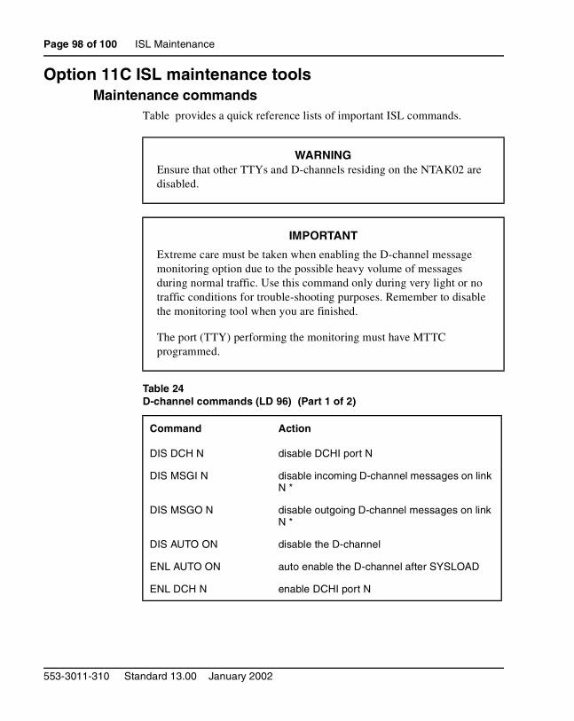
Page 98 of 100 ISL Maintenance
Option 11C ISL maintenance toolsMaintenance commands
Table provides a quick reference lists of important ISL commands.
WARNINGEnsure that other TTYs and D-channels residing on the NTAK02 are disabled.
IMPORTANT
Extreme care must be taken when enabling the D-channel message monitoring option due to the possible heavy volume of messages during normal traffic. Use this command only during very light or no traffic conditions for trouble-shooting purposes. Remember to disable the monitoring tool when you are finished.
The port (TTY) performing the monitoring must have MTTC programmed.
Table 24D-channel commands (LD 96) (Part 1 of 2)
Command Action
DIS DCH N disable DCHI port N
DIS MSGI N disable incoming D-channel messages on link N *
DIS MSGO N disable outgoing D-channel messages on link N *
DIS AUTO ON disable the D-channel
ENL AUTO ON auto enable the D-channel after SYSLOAD
ENL DCH N enable DCHI port N
553-3011-310 Standard 13.00 January 2002
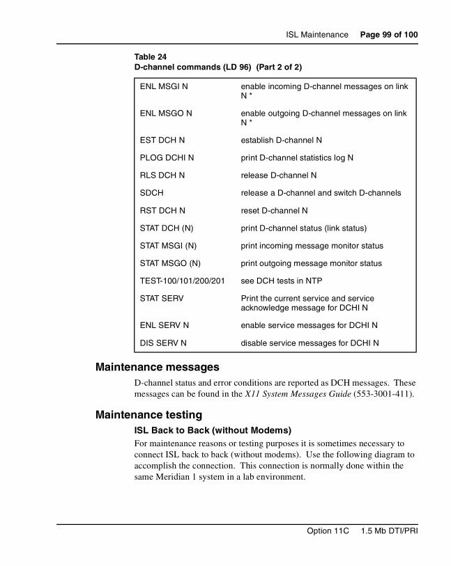
ISL Maintenance Page 99 of 100
Maintenance messagesD-channel status and error conditions are reported as DCH messages. These messages can be found in the X11 System Messages Guide (553-3001-411).
Maintenance testingISL Back to Back (without Modems)For maintenance reasons or testing purposes it is sometimes necessary to connect ISL back to back (without modems). Use the following diagram to accomplish the connection. This connection is normally done within the same Meridian 1 system in a lab environment.
ENL MSGI N enable incoming D-channel messages on link N *
ENL MSGO N enable outgoing D-channel messages on link N *
EST DCH N establish D-channel N
PLOG DCHI N print D-channel statistics log N
RLS DCH N release D-channel N
SDCH release a D-channel and switch D-channels
RST DCH N reset D-channel N
STAT DCH (N) print D-channel status (link status)
STAT MSGI (N) print incoming message monitor status
STAT MSGO (N) print outgoing message monitor status
TEST-100/101/200/201 see DCH tests in NTP
STAT SERV Print the current service and service acknowledge message for DCHI N
ENL SERV N enable service messages for DCHI N
DIS SERV N disable service messages for DCHI N
Table 24D-channel commands (LD 96) (Part 2 of 2)
Option 11C 1.5 Mb DTI/PRI
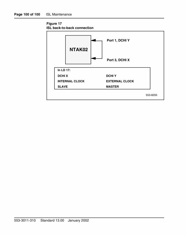
Page 100 of 100 ISL Maintenance
Figure 17ISL back-to-back connection
NTAK02
Port 1, DCHI Y
Port 3, DCHI X
In LD 17:
DCHI X DCHI Y
INTERNAL CLOCK EXTERNAL CLOCK
SLAVE MASTER
553-8293
553-3011-310 Standard 13.00 January 2002

1
Family Product Manual Contacts Copyright FCC notice TrademarksDocument number Product release Document release Date Publish
Meridian 1
Option 11C1.5 Mb DTI/PRI
Copyright © 1992–2002 Nortel NetworksAll Rights ReservedInformation is subject to change without notice. NortelNetworks reserves the right to make changes indesign or components as progress in engineering andmanufacturing may warrant. This equipment has beentested and found to comply with the limits for a Class Adigital device pursuant to Part 15 of the FCC rules,and the radio interference regulations of IndustryCanada. These limits are designed to providereasonable protection against harmful interferencewhen the equipment is operated in a commercialenvironment. This equipment generates, uses and canradiate radio frequency energy, and if not installed andused in accordance with the instruction manual, maycause harmful interference to radio communications.Operation of this equipment in a residential area islikely to cause harmful interference in which case theuser will be required to correct the interference at theirown expense.SL-1 and Meridian 1 are trademarks of NortelNetworks.Publication number: 553-3011-310Document release: Standard 13.00Date: January 2002Printed in Canada
TM