Embed Size (px)
Citation preview

Meridian 1
Network ACDDescription and operation
Document Number: 553-3671-120Document Release: Standard 10.00Date: April 2000
Year Publish FCC TM
Copyright © 1989–2000 Nortel NetworksAll Rights Reserved
Printed in Canada
Information is subject to change without notice. Nortel Networks reserves the right to make changes in design or components as progress in engineering and manufacturing may warrant. This equipment has been tested and found to comply with the limits for a Class A digital device pursuant to Part 15 of the FCC rules, and the radio interference regulations of Industry Canada. These limits are designed to provide reasonable protection against harmful interference when the equipment is operated in a commercial environment. This equipment generates, uses and can radiate radio frequency energy, and if not installed and used in accordance with the instruction manual, may cause harmful interference to radio communications. Operation of this equipment in a residential area is likely to cause harmful interference in which case the user will be required to correct the interference at their own expense.
SL-1 and Meridian 1 are trademarks of Nortel Networks.
Network ACD Description and operation

Page 3 of 140
4
ase nces nces
this
s
21
ing.
n.
.
Revision historyApril 2000
Standard 10.00. This is a global document and is up-issued for X11 Rele25.0x. Document changes include removal of: redundant content; refereto equipment types except Options 11C, 51C, 61C, and 81C; and refereto previous software releases. .
June 1999Standard, issue 9.00. This is the X11 Release 24.2x standard version ofdocument.
October 1997Standard, issue 8.00. This is the X11 Release 23 standard version of thidocument.
December 1995Standard, release 7.00. Reissued to include editorial changes.
July 1995Standard, release 6.00. This document is issued to include X11 Releasechanges.
December 1994Standard, release 5.00. Reissued to include editorial changes and index
August 1993Standard, release 4.00. Reissued to include updates and new informatio
December 1992Standard, release 3.00. Reissued to include updates for X11 Release 18
Network ACD Description and operation

Page 4 of 140 Revision History
ervice this
December 1991Standard, release 2.00. Reissued to include technical content updates. Schange and system error message information has been removed from document. Refer to the X11 Administration (553-3001-311) for this information.
December 1989Standard, release 1.00. Reissued for compliance with Nortel Networks standard 164.0 and to include updates for X11Release 15.
553-3671-120 Standard 10.00 April 2000
Page 5 of 140
8
9
10
11
14
15151515161617
17
18
20
22
2323
2728
28
30
31
31
Contents
General information . . . . . . . . . . . . . . . . . . . . . . . . 9Content list . . . . . . . . . . . . . . . . . . . . . . . . . . . . . . . . . . . . . . . . . . . . . .
Reference list . . . . . . . . . . . . . . . . . . . . . . . . . . . . . . . . . . . . . . . . . . . .
Overview . . . . . . . . . . . . . . . . . . . . . . . . . . . . . . . . . . . . . . . . . . . . . . .
Enhanced Overflow . . . . . . . . . . . . . . . . . . . . . . . . . . . . . . . . . . . . . . .
Network ACD overview . . . . . . . . . . . . . . . . . . . . . . . . . . . . . . . . . . . . Environment . . . . . . . . . . . . . . . . . . . . . . . . . . . . . . . . . . . . . . . . . . NACD on a 911 application . . . . . . . . . . . . . . . . . . . . . . . . . . . . . . Call Processing . . . . . . . . . . . . . . . . . . . . . . . . . . . . . . . . . . . . . . . . Call Request queue . . . . . . . . . . . . . . . . . . . . . . . . . . . . . . . . . . . . . Engineering . . . . . . . . . . . . . . . . . . . . . . . . . . . . . . . . . . . . . . . . . . . Management reports . . . . . . . . . . . . . . . . . . . . . . . . . . . . . . . . . . . . Collect Call Blocking (Brazil) . . . . . . . . . . . . . . . . . . . . . . . . . . . . .
Operating parameters . . . . . . . . . . . . . . . . . . . . . . . . . . . . . . . . . . . . . .
Feature interactions . . . . . . . . . . . . . . . . . . . . . . . . . . . . . . . . . . . . . . .
Feature packaging . . . . . . . . . . . . . . . . . . . . . . . . . . . . . . . . . . . . . . . .
Feature implementation . . . . . . . . . . . . . . . . . . . . . . . . . . . . . . . . . . . . Task summary list . . . . . . . . . . . . . . . . . . . . . . . . . . . . . . . . . . . . . .
Feature operation . . . . . . . . . . . . . . . . . . . . . . . . . . . . . . . . . . . . . . . . . Meridian Link Predictive Dialing Support . . . . . . . . . . . . . . . . . . .
Operating parameters . . . . . . . . . . . . . . . . . . . . . . . . . . . . . . . . . . . . . .
Feature interactions . . . . . . . . . . . . . . . . . . . . . . . . . . . . . . . . . . . . . . .
Feature packaging . . . . . . . . . . . . . . . . . . . . . . . . . . . . . . . . . . . . . . . .
Feature implementation . . . . . . . . . . . . . . . . . . . . . . . . . . . . . . . . . . . .
Network ACD Description and operation
Page 6 of 140 Contents
31
4545
49
51
55
58
5959
69
707071
71
71717272
73
74
7475788183
8484858687
8888
Task summary list . . . . . . . . . . . . . . . . . . . . . . . . . . . . . . . . . . . . . .
Feature operation . . . . . . . . . . . . . . . . . . . . . . . . . . . . . . . . . . . . . . . . . Meridian 911 . . . . . . . . . . . . . . . . . . . . . . . . . . . . . . . . . . . . . . . . . .
Operating parameters . . . . . . . . . . . . . . . . . . . . . . . . . . . . . . . . . . . . . .
Feature interactions (Meridian 911) . . . . . . . . . . . . . . . . . . . . . . . . . .
Feature interaction (Meridian 911 Call Abandon) . . . . . . . . . . . . . . . .
Feature packaging . . . . . . . . . . . . . . . . . . . . . . . . . . . . . . . . . . . . . . . .
Feature implementation . . . . . . . . . . . . . . . . . . . . . . . . . . . . . . . . . . . . Task summary list . . . . . . . . . . . . . . . . . . . . . . . . . . . . . . . . . . . . . .
Feature operation . . . . . . . . . . . . . . . . . . . . . . . . . . . . . . . . . . . . . . . . .
ISDN overview . . . . . . . . . . . . . . . . . . . . . . . . . . . . . . . . . . . . . . . . . . Primary Rate Interface (PRI) . . . . . . . . . . . . . . . . . . . . . . . . . . . . . D-channel . . . . . . . . . . . . . . . . . . . . . . . . . . . . . . . . . . . . . . . . . . . . ISDN Signaling Link (ISL) . . . . . . . . . . . . . . . . . . . . . . . . . . . . . . .
Supporting documents . . . . . . . . . . . . . . . . . . . . . . . . . . . . . . . . . . . . . ACD . . . . . . . . . . . . . . . . . . . . . . . . . . . . . . . . . . . . . . . . . . . . . . . . ISDN . . . . . . . . . . . . . . . . . . . . . . . . . . . . . . . . . . . . . . . . . . . . . . . . System support documents . . . . . . . . . . . . . . . . . . . . . . . . . . . . . . .
NACD Functional description . . . . . . . . . . . . . . . . 73Content list . . . . . . . . . . . . . . . . . . . . . . . . . . . . . . . . . . . . . . . . . . . . . .
Reference list . . . . . . . . . . . . . . . . . . . . . . . . . . . . . . . . . . . . . . . . . . . .
Network environment . . . . . . . . . . . . . . . . . . . . . . . . . . . . . . . . . . . . . Routing Tables . . . . . . . . . . . . . . . . . . . . . . . . . . . . . . . . . . . . . . . . Source Table Viewer . . . . . . . . . . . . . . . . . . . . . . . . . . . . . . . . . . . . Cascade routing . . . . . . . . . . . . . . . . . . . . . . . . . . . . . . . . . . . . . . . . Dynamic status change . . . . . . . . . . . . . . . . . . . . . . . . . . . . . . . . . .
Incoming calls . . . . . . . . . . . . . . . . . . . . . . . . . . . . . . . . . . . . . . . . . . . Call Requests . . . . . . . . . . . . . . . . . . . . . . . . . . . . . . . . . . . . . . . . . . Canceling Call Requests . . . . . . . . . . . . . . . . . . . . . . . . . . . . . . . . . Queue priorities . . . . . . . . . . . . . . . . . . . . . . . . . . . . . . . . . . . . . . . . Call presentation . . . . . . . . . . . . . . . . . . . . . . . . . . . . . . . . . . . . . . .
Feature interactions . . . . . . . . . . . . . . . . . . . . . . . . . . . . . . . . . . . . . . . ACD interactions . . . . . . . . . . . . . . . . . . . . . . . . . . . . . . . . . . . . . . .
553-3671-120 Standard 10.00 April 2000
Contents Page 7 of 140
96
97
99
9999
101
101102
104104
105
106106106107
107107
108081081090909110110
11
11111112112113
115
Feature interactions . . . . . . . . . . . . . . . . . . . . . . . . . . . . . . . . . . . . .
NACD Engineering . . . . . . . . . . . . . . . . . . . . . . . . . 97Content list . . . . . . . . . . . . . . . . . . . . . . . . . . . . . . . . . . . . . . . . . . . . . .
Reference list . . . . . . . . . . . . . . . . . . . . . . . . . . . . . . . . . . . . . . . . . . . .
Dependencies . . . . . . . . . . . . . . . . . . . . . . . . . . . . . . . . . . . . . . . . . . . . Package dependencies . . . . . . . . . . . . . . . . . . . . . . . . . . . . . . . . . . .
Feature limitations . . . . . . . . . . . . . . . . . . . . . . . . . . . . . . . . . . . . . . . .
Feature requirements . . . . . . . . . . . . . . . . . . . . . . . . . . . . . . . . . . . . . . ESN requirements . . . . . . . . . . . . . . . . . . . . . . . . . . . . . . . . . . . . . .
Recommendations . . . . . . . . . . . . . . . . . . . . . . . . . . . . . . . . . . . . . . . . Customer configurations . . . . . . . . . . . . . . . . . . . . . . . . . . . . . . . . .
NACD engineering guidelines . . . . . . . . . . . . . . . . . . . . . . . . . . . . . . .
Target table definition . . . . . . . . . . . . . . . . . . . . . . . . . . . . . . . . . . . . . Real-time impact . . . . . . . . . . . . . . . . . . . . . . . . . . . . . . . . . . . . . . . Noncoincidence busy hour (time zone difference) . . . . . . . . . . . . . ACD DN load at each node (spare capacity) . . . . . . . . . . . . . . . . . . Agent group size in an ACD DN . . . . . . . . . . . . . . . . . . . . . . . . . . . Number of hops . . . . . . . . . . . . . . . . . . . . . . . . . . . . . . . . . . . . . . . .
Parameter definition . . . . . . . . . . . . . . . . . . . . . . . . . . . . . . . . . . . . . . . Flow Control (Overlay 23: FCTH) . . . . . . . . . . . . . . . . . . . . . . . . . 1Call Request Queue Size (Overlay 23: CRQS) . . . . . . . . . . . . . . . . Resend Timer (Overlay 23: RSND) . . . . . . . . . . . . . . . . . . . . . . . . Reserve Agent Timer (Overlay 23: RAGT) . . . . . . . . . . . . . . . . . . 1Oldest Call in Network (Overlay 23: OCN) . . . . . . . . . . . . . . . . . . 1ACD agents requirement at each node . . . . . . . . . . . . . . . . . . . . . . Trunking requirements at the Source and Target nodes . . . . . . . . . Duration Timer (Overlay 23: DURT) . . . . . . . . . . . . . . . . . . . . . . . 1
Network requirements . . . . . . . . . . . . . . . . . . . . . . . . . . . . . . . . . . . . . Signaling link requirements between Source and Target nodes . . . Overflow traffic estimation . . . . . . . . . . . . . . . . . . . . . . . . . . . . . . . 1Average CCS loading per agent at each ACD DN . . . . . . . . . . . . . Call register requirements . . . . . . . . . . . . . . . . . . . . . . . . . . . . . . . .
Designing the NACD Routing Table . . . . . . . . . . . . . . . . . . . . . . . . . .
Network ACD Description and operation

Page 8 of 140 Contents
1161161171171819
1221222323
123124124125
129
129
129
130
130130
130130133
ACD agent group size (P1) . . . . . . . . . . . . . . . . . . . . . . . . . . . . . . . Average agent load at each target ACD DN (P2) . . . . . . . . . . . . . . Number of hops (P3) . . . . . . . . . . . . . . . . . . . . . . . . . . . . . . . . . . . . Noncoincidence busy hour and time zone difference (P4) . . . . . . . Ranking of Target nodes on NACD Routing Table . . . . . . . . . . . . 1Timer value in NACD Routing Table . . . . . . . . . . . . . . . . . . . . . . . 1
Incremental impact engineering . . . . . . . . . . . . . . . . . . . . . . . . . . . . . . Trunking requirement . . . . . . . . . . . . . . . . . . . . . . . . . . . . . . . . . . . Trunk traffic to source ACD DN . . . . . . . . . . . . . . . . . . . . . . . . . . 1Overflow traffic from source ACD DN . . . . . . . . . . . . . . . . . . . . . 1Calls handled by the Source node agents . . . . . . . . . . . . . . . . . . . . Incremental traffic to each Target node . . . . . . . . . . . . . . . . . . . . . Real-time requirement . . . . . . . . . . . . . . . . . . . . . . . . . . . . . . . . . . . Call register requirement . . . . . . . . . . . . . . . . . . . . . . . . . . . . . . . . .
Implementation . . . . . . . . . . . . . . . . . . . . . . . . . . . . 127
Operations . . . . . . . . . . . . . . . . . . . . . . . . . . . . . . . . 129Content list . . . . . . . . . . . . . . . . . . . . . . . . . . . . . . . . . . . . . . . . . . . . . .
Reference list . . . . . . . . . . . . . . . . . . . . . . . . . . . . . . . . . . . . . . . . . . . .
Agent telephone displays . . . . . . . . . . . . . . . . . . . . . . . . . . . . . . . . . . .
Management reports . . . . . . . . . . . . . . . . . . . . . . . . . . . . . . . . . . . . . .
Administration and operational measurements . . . . . . . . . . . . . . . . . . Service change . . . . . . . . . . . . . . . . . . . . . . . . . . . . . . . . . . . . . . . .
Feature implementation . . . . . . . . . . . . . . . . . . . . . . . . . . . . . . . . . . . . Task summary list . . . . . . . . . . . . . . . . . . . . . . . . . . . . . . . . . . . . . . Traffic measurements . . . . . . . . . . . . . . . . . . . . . . . . . . . . . . . . . . .
Index . . . . . . . . . . . . . . . . . . . . . . . . . . . . . . . . . . . . 135
553-3671-120 Standard 10.00 April 2000
Page 9 of 140
72
General informationContent list
The following are the topics in this section:
• Reference list 10
• Overview 11
• Enhanced Overflow 14
• Network ACD overview 15
• Environment 15
• NACD on a 911 application 15
• Call Processing 15
• Call Request queue 16
• Engineering 16
• Management reports 17
• Collect Call Blocking (Brazil) 17
• Operating parameters 18
• Feature interactions 20
• Feature packaging 22
• Feature implementation 23
• Task summary list 23
• Feature operation 27
• Meridian Link Predictive Dialing Support 28
Network ACD Description and operation

Page 10 of 140 General information
• Operating parameters 28
• Feature interactions 30
• Feature packaging 31
• Feature implementation 31
• Task summary list 31
• Feature operation 45
• Meridian 911 45
• Operating parameters 49
• Feature interactions (Meridian 911) 51
• Feature interaction (Meridian 911 Call Abandon) 55
• Feature packaging 58
• Feature implementation 59
• Task summary list 59
• Feature operation 69
• ISDN overview 70
• Primary Rate Interface (PRI) 70
• D-channel 71
• ISDN Signaling Link (ISL) 71
• Supporting documents 71
• ACD 71
• ISDN 72
• System support documents 72
Reference listThe following are the references in this section:
• Electronic Switched Network Signaling Guidelines (309-3001-180)
• Electronic Switched Network Transmission Guidelines (309-3001-181)
553-3671-120 Standard 10.00 April 2000
General information Page 11 of 140
ur
ting
l
5 or
• Automatic Call Distribution: Feature Description (553-2671-110)
• Automatic Call Distribution: Management Commands and Reports (553-2671-112)
• Basic and Network Alternate Route Selection: Description (553-2751-100)
• Coordinated Dialing Plan: Description (553-2751-102)
• X11 Networking Features and Services (553-2901-301)
• X11 Features and Services (553-3001-306)
OverviewThis document is a global document. Contact your system supplier or yoNortel Networks representative to verify that the hardware and softwaredescribed is supported in your area.
Enhanced Overflow (EOVF) vastly expands the operations for overflow queues and Target queues within an existing Automatic Call Distribution(ACD) switch. The Enhanced Overflow package can operate in any exisACD application.
Network ACD supports ACD functions over an Integrated Service DigitaNetwork (ISDN). All the requirements for ISDN are required for Network ACD.
This is a descriptive and administrative publication for the Enhanced Overflow feature and Network ACD. This feature requires X11 Release 2higher and is supported on the following machine types:
• System Options 11C, 51C, 61C, and 81 C.
The following features are available also:
• Collect Call Blocking (Brazil) provides a mechanism for special treatment of incoming DID and CO collect calls on 2 Mbit/sec digitaltrunks and analog trunks. This feature is provided on a route and individual user basis.
• Meridian Link Predictive Dialing Support
Network ACD Description and operation
Page 12 of 140 General information
d
e
ish
h
r
ory
tal
can
CD stem o
be
• M911 Enhancements include Call Abandon and MADN Display Coordination. Call Abandon provides the ability to treat an abandonecall as though the calling party remained online. MADN Display Coordination adds the Application Module Link, Meridian Link, and Application Module Base Application Program Interface (API) messages that enable Meridian 911 and ML applications to provide display coordination for a call taker that holds/receives multiple activcalls across a MADN.
• Multiple Queue Assignments allows ACD agents to service calls frommultiple ACD queues simultaneously, and choose the queues they wto service at login.
Before using this document, you must have a working knowledge of botACD and Integrated Service Digital Networks. Refer to the publications listed on page 71 for related background information.
This section is an introduction to the Network ACD application. Details fothe administration and operation of the features are covered later in thisdocument.
Enhanced Overflow (EOVF) increases the number of Target ACD DirectNumbers (DNs) from 6 to 100 within the existing Time Overflow (TOF) feature application. As a stand-alone feature, it works only in local applications. EOVF alone does not provide network services, but is prerequisite for Network Automatic Call Distribution (NACD).
Network ACD provides ACD capabilities over an Integrated Service DigiNetwork (ISDN). An NACD system distributes ACD activities between several sites. Connected by ISDN voice and data services, different sitesbe physically or geographically separated within the network.
System operations and call overflows are transparent to the caller. The Aagents notice some display changes; however, ACD supervisors and sytechnicians must be aware of the configuration and operation of NACD tproperly support the application for a customer.
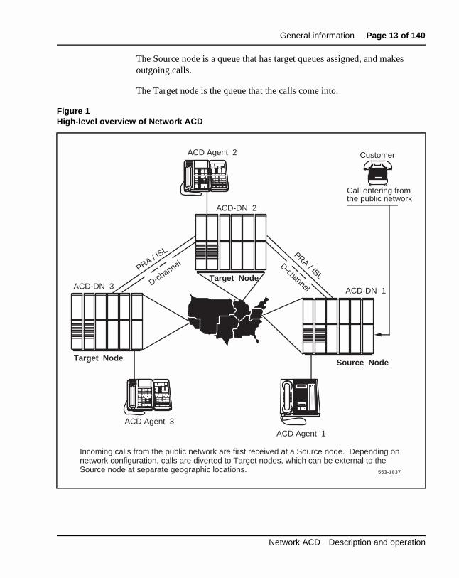
With EOVF and NACD enabled and supported in the network, calls can serviced as shown in Figure 1.
553-3671-120 Standard 10.00 April 2000
General information Page 13 of 140
s
The Source node is a queue that has target queues assigned, and makeoutgoing calls.The Target node is the queue that the calls come into.
Figure 1High-level overview of Network ACD
ACD-DN 2
ACD-DN 1ACD-DN 3
Customer
Call entering from the public network
ACD Agent 2
ACD Agent 1
ACD Agent 3
Source Node
Target Node
Target Node
Incoming calls from the public network are first received at a Source node. Depending on network configuration, calls are diverted to Target nodes, which can be external to the Source node at separate geographic locations.
PRA / ISL PRA / ISL
D-channel D-channel
553-1837
Network ACD Description and operation
Page 14 of 140 General information
ach
N.
se the pt
N d ter in
r of
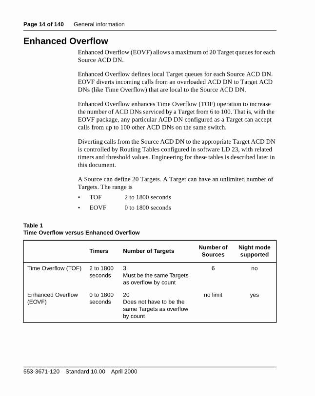
Enhanced Overflow Enhanced Overflow (EOVF) allows a maximum of 20 Target queues for eSource ACD DN.
Enhanced Overflow defines local Target queues for each Source ACD DEOVF diverts incoming calls from an overloaded ACD DN to Target ACDDNs (like Time Overflow) that are local to the Source ACD DN.
Enhanced Overflow enhances Time Overflow (TOF) operation to increathe number of ACD DNs serviced by a Target from 6 to 100. That is, with EOVF package, any particular ACD DN configured as a Target can accecalls from up to 100 other ACD DNs on the same switch.
Diverting calls from the Source ACD DN to the appropriate Target ACD Dis controlled by Routing Tables configured in software LD 23, with relatetimers and threshold values. Engineering for these tables is described lathis document.
A Source can define 20 Targets. A Target can have an unlimited numbeTargets. The range is
• TOF 2 to 1800 seconds
• EOVF 0 to 1800 seconds
Table 1Time Overflow versus Enhanced Overflow
Timers Number of TargetsNumber of Sources
Night mode supported
Time Overflow (TOF) 2 to 1800 seconds
3Must be the same Targets as overflow by count
6 no
Enhanced Overflow (EOVF)
0 to 1800 seconds
20Does not have to be the same Targets as overflow by count
no limit yes
553-3671-120 Standard 10.00 April 2000
General information Page 15 of 140
ian to call
g to
ct n
e
e nd
s f up all
rted o
Network ACD overviewEnvironment
The Enhanced Overflow (EOVF) (package 178) is required to support Network ACD (NACD). Network ACD (package 207) allows ACD functionality between physically separated locations in a multinode Merid1 network. This allows ACD agent groups at different locations (nodes) service calls over the network at remote targets, independent of where thefirst entered the network. Network ACD uses ISDN D-channel messaginexchange information between nodes.
NACD on a 911 applicationIf the incoming route is set up with CPDC = YES and it uses CDP to direthe call to queue 2 without using NACD, the call will go to queue 2. For aNACD application, CPDC must be set to NO.
Call ProcessingLike EOVF, Network ACD allows Target queues to be defined for SourcACD DNs. Network ACD can define Source and Target queues for eachACD DN. NACD diverts incoming calls from an overloaded ACD DN to Target ACD DNs (like EOVF), which can be local or remote to the SourcACD DN. Local Targets are on the same node as the Source ACD DN, aremote Targets are at a different node.
Diverting calls in NACD is controlled by Routing Tables with timers. Calldiverted by NACD can be answered by the Source ACD DN or any one oto 20 Target ACD DNs. By using ISDN D-channel messaging to queue CRequests at remote Target ACD DNs, voice calls are not physically diveuntil an idle agent is reserved for that call at the remote Target node. If ntrunks are available, a call doesn’t go across the network. If trunks are available, the agent is reserved until the timer expires.
Refer to “Designing the NACD Routing Table” on page 115.
Network ACD Description and operation
Page 16 of 140 General information
the nnel
he tion.
ent call ive
ent
ot nt
cancel
l an
r tain tions
the
When the Target timer expires and there are no idle agents available at Source node, NACD software sends a Call Request over the ISDN D-chato a defined Target ACD DN. An idle Target agent is matched with an individual Call Request. That Target agent is reserved for that call, and tTarget node responds through the D-channel with an Agent Free notificaWhen the Agent Free notification is sent, the agent is reserved and a customer-defined Reserve Agent Timer starts. Only after receiving the AgFree notification does the NACD Source node physically divert the voice to the Target ACD DN. When reserved, an agent is not available to receACD calls from any other queue.
The Reserve Agent Timer (RAGT), as configured in LD 23, prevents an agfrom being reserved indefinitely and unavailable for calls. A timer countdown is shown on the agent’s Digit Display if desired. If the call is npresented before the timer expires, the agent is returned to the Idle Agequeue and the call remains in place in the Source node.
There are some situations that can change an agent’s reserved status or a Call Request; these situations are described later in this document.
Call Request queueTarget ACD DNs have an additional queue created to handle incoming NACD traffic—the Call Request queue. Logical Call Requests (not physical calls) are queued in the Call Request queue for the Target ACD DN untiagent is available.
EngineeringOperating parameters for NACD must be carefully engineered for propefunctioning. To interact with supporting systems, this feature requires cerconfigurations. In order to protect other feature operations, some precauare suggested in “NACD Engineering” on page 97.
The NACD engineering section also contains a list of all hardware and software requirements for Networking ACD applications. Be sure to readentire section before starting to implement NACD.
553-3671-120 Standard 10.00 April 2000
General information Page 17 of 140
bled ss
he es
nt sented f
splay
n
)
ute
ed
The NACD feature requires ISDN to be active between the sites and enafor NACD. Take special note of the sections in this document that addrepackage requirements, feature engineering, and feature interactions.
Network ACD is a separate package from the ACD packages. Refer to t“Engineering” on page 16 for a complete list of the package dependenciinvolved.
Dialing plan configuration is critical to NACD operation. See “NACD engineering guidelines” on page 105.
Management reportsPackage C for ACD provides reports to assist ACD supervisors with ageand traffic statistics. Although no new fields are introduced in the outputreports, the reports are changed by circumstance because calls are preor received at potentially diverse locations. Supervisors must be aware onetwork operations, because the values presented in the supervisor’s diare affected by NACD.
Details for changes to Management reports are covered in the section ooperations in this document. See “Management reports” on page 130.
Collect Call Blocking (Brazil)In Brazil an automatic long distance collect call service called DDC is available. The collect Call Blocking feature enables a Meridian 1 administrator to block DDC calls on incoming Direct Inward dialing (DIDand Public Exchange/Control Office trunks (analog or DT12). Under thefollowing conditions, the Meridian 1 sends a special answer signal to theCentral Office that collect calls that cannot be accepted:
• The Collect Call Blocking (CCB) package 290 is enabled
• The incoming route has CCB enabled via the CCB prompt in the RoData Block, and
• The call is answered by a CCB user (i.e., Collect Call Blocking AllowClass of Service or option).
Network ACD Description and operation

Page 18 of 140 General information
cific
.
mer
t.
l for
ct
and
nd
e ng.
ere
o
New Classes of Service and prompts have been introduced to inhibit speusers for receiving collect DID and Central Office calls. These can be configured for the following:
• Analog (500/2500 type) and Meridian 1 proprietary sets, through theCollect Call Blocking Allowed/Denied (CCBA/CCBD) Class of Service
• Attendant and Network Alternate Route Selection calls on a per custobasis through CCBA/CCBD option.
• Automatic Call Distribution (ACD) queues through the CCBA promp
• Direct Inward system Access (DISA) through the CCBA prompt.
• Tandem calls dialed with Coordinated Dialing Plan (CDP) (Trunk Steering Code, Distant Steering Code) through the CCBA prompt.
• Tandem non-CDP calls through the CCBA prompt in the Route DataBlock from the outgoing trunk route.
The Meridian 1 sends the CCB answer signal in place of the regular signaincoming DID/CO calls from routes with CCB enabled, when a call is answered by a CCB user. If the call is a collect call, the CO will disconnethe call.
Operating parametersThe Collect Call Blocking feature supports both analog and DT12 trunks, the following Intelligent Peripheral Equipment (IPE) cards:
• The NTCK 16BB Extended Flexible COT Trunk Card (XFCOT) with firmware flash timing
• The NT8D14BA Enhanced Extended Universal Trunk Card (EXUT) containing the Centrex Switchhook Flash function in the firmware, a
• The NT8K14AK Extended Universal Trunk Card (XUT) which may bused if the Centrex Switchhook Flash is configured with software timi
• The Collect Call Blocking answer signal can only be sent in cases whanswer supervision is provided by the Meridian 1.
Once the modified answer signal is sent to the CO, the Meridian 1 has ncontrol over how the call will be handled by the CO.
553-3671-120 Standard 10.00 April 2000
General information Page 19 of 140
g nd nd
swer
se nt.
it
that er any
he for the B2
CB ling
are ard imer
If a CCB user answers a call from a CO/DID route with Collect Call Blockinactivated, the CCB answer signal is sent to the CO for all incoming DID aCO calls. For analog trunks, the user will experience clicking on the line aa temporary break is speechpath (0.5 to 2.5 seconds) while the CCB ansignal is being sent.
If the XFCOT and EXUT cards do not have flexible firmware timing, the CCB flash portion of the CCB answer signal will be returned to the CO. However, software controlled signaling can be done with EXUT cards.
In a standalone environment, all input from a set (except from the Releakey) is ignored while the Collect Call Blocking answer signal is being se
Collect Call Blocking is applied to attendants on a customer basis only; cannot be applied on a tenant basis.
The answer signal returned for a call from a route with CCB enabled andis Network Attendant Service (NAS) routed is determined by the customoption on the source node. Thus, NAS routing can be configured acrossMeridian Customer Defined Network environment, but the source node determines the answer supervision sent to the CO.
Call Detail Recording (CDR) record timing begins on the first answer of tCCB answer sequence. For this reason, CDR records will be generatedincoming calls to CCB users across routes on which CCB is enabled. If call is collect, and is dropped, a CDR record of approximately CCB1 + CClength will be generated.
For data calls all calls will be answered with the CCB answer signal, if Cis enabled. This may have an effect on data protocols, while CCB signais taking place.
If firmware timing is used (FWTM = YES in LD 14) for sending the CCB flash, the CCB2 timer is downloaded to the card before sending the firmwflash. If the CCB2 timer is changed in the Route Data Block, either the chas to be enabled or the switch has to be initialized to get the new CCB2 tdownloaded to the card.
Network ACD Description and operation
Page 20 of 140 General information
1 an ed, lass
an
f the me
, al r
e D eue
e
CB
a l is
Feature interactionsAutomatic AnswerbackThe Automatic Answerback (AAB) feature, when assigned to a Meridianproprietary set, allows any incoming N) to be answered automatically. Ifincoming DID or CO call terminates on a set with the AAB feature enablthe call is automatically answered after one ring. If the set has a CCBA Cof Service, the CCB answer signal is provided in the place of the regularanswer signal.
Automatic Call Distribution Collect Call Blocking can be enabled on an ACD queue basis. Hence, ifincoming CO or DID call is answered by an ACD agent, the answer supervision signal that is returned to the CO is determined by the value oCCBA prompt in LD 23. While the CCB answer signal is being sent, the salimitations apply to ACD as apply to sets with CCBA Class of Service.
Automatic Call Distribution InterflowIf an ACD call from a route with CCB enabled is diverted to an interflow DNand answer supervision has not already been provided, the answer signreturned to the CO depends on the source ACD queue. The CCB answesignal is returned to the CO if the source ACD queue has CCB enabled.
Automatic Call Distribution Night Call ForwardIf an ACD call from a route with CCB enabled is diverted to a Night Call Forward DN, and answer supervision has not already been provided, thanswer supervision signal returned to the CO depends on the source ACqueue. The CCB answer signal is returned to the CO if the source ACD quhas CCB enabled.
Automatic Call Distribution Night RAN Route AnnouncementIf an ACD call from a route with CCB enabled is diverted to a Night RANroute (defined by NRRT in the ACD block), the CCB signal returned to thCO depends on the source ACD queue. If the source ACD queue has Cenabled, the CCB answer signal is sent to the CO.
AutoterminateIf an incoming DID or CO call from an autoterminate trunk terminates onset or ACD queue with a CCBA Class of Service, the CCB answer signaprovided in place of the regular answer signal.
553-3671-120 Standard 10.00 April 2000
General information Page 21 of 140
ect
ntral n .
the
ase
CD ian
e a ian e.e, .e,
Basic Rate Interface (BRI) SetsFor BRI sets CCBA/CCBD Class of Service cannot be programmed. Therefore, it is not possible to prevent BRI sets from accepting DDC collcalls.
Central Answering Position (CAP)The answer signal returned to the CO for calls that get answered by a CeAnswering Position (CAP) is determined by the source ACD configuratioand not the customer option (CCBA/CCBD in LD 15) on the source node
Centralized Attendant ServiceThe answer signal returned to the CO for calls that get answered by a Centralized Attendant Service is determined by the customer option (CCBA/CCDB in LD 15) on the source node.
Centrex Switchhook FlashA Centrex Switchhook Flash cannot be invoked by another feature whileCCB answer signal is being sent.
Enhanced Malicious Call TraceIf a station activates Malicious Call Trace (MCT) while the CCB answer signal is being sent, MCT activation is ignored. This also applies to the cwhen MCT is activated from a remote node.
Meridian MailBecause Meridian Mail is configured using ACD queues, the same interactions exist as in the ACD case. When Meridian Mail sends a call answer message to the Meridian 1, the CCB configuration in the source Aqueue is used to determine if a CCB answer signal should be sent to theCentral Office. All mail boxes using the same ACD queue to access MeridMail will get the same CCB treatment.
If some of the mail boxes are allowed to receive collect calls, this may bproblem. A possible solution is to configure two ACD queues on the Merid1 to access Meridian Mail. One queue would have collect calls allowed (i.CCBA = NO) and the second queue would have collect calls denied (i.eCCBA = YES).
Network ACD Description and operation
Page 22 of 140 General information
te e of
N, tion
et e of
the he the
it dem sent
F
e
Network Automatic Call DistributionThe answer signal returned to the CO for a network ACD call from a rouwith CCB enabled is determined by the source ACD queue. If the sourceACD queue has CCB enabled, the CCB answer signal is returned in placthe regular answer signal.
Pilot DNIf an incoming DID or CO call has CCB enabled and is routed to a pilot Dthe answer signal returned to the CO is determined by the CCB configuraof the terminating station.
Private Line ServiceIf an incoming DID or CO call from a private line trunk terminates on a swith a CCBA Class of Service, the CCB answer signal is provided in placthe regular answer signal.
Recorded Announcement (RAN)A RAN route is defined as having CCBA YES or NO, which is used if Coordinated Dialing Plan (CDP) or ACD queues were not used to get toRAN route. If the call is routed through ACD/CDP to terminate on RAN, tCCB treatment will depend upon the CCB data of the ACD/CDP, and notRAN route.
Tandem to Unsupervised TrunkIf an incoming DID or CO call tandems to an unsupervised trunk before terminates, the answer signal is sent by time-out. Therefore, any CCB tancalls made to unsupervised trunks will not have the CCB answer signal until the time-out occurs.
Trunk Hook Flash (THF)If a station activates THF while the CCB answer signal is being sent, THactivation is ignored.
Feature packagingCollect Call Blocking (CCB) package 290 must be provisioned to activatthis feature.
553-3671-120 Standard 10.00 April 2000
General information Page 23 of 140
s.
e)
y
Feature implementationTask summary list
The following is a summary of the tasks in this section:
1 LD 16 – Enable Collect Call Blocking on a route and configure timer
2 LD 14 – Set up the firmware timing for XFCOT and EXUT cards.
3 LD 15 – Add or change Collect Call Blocking for attendants.
4 LD 10 – Add or change Collect Call Blocking for analog (500/2500 typsets.
5 LD 11 – Add or change Collect Call Blocking for Meridian 1 proprietarsets.
6 LD 23 – Enable Collect Call Blocking on ACD queues.
7 LD 24 – Enable Collect Call Blocking on DISA blocks.
8 LD 87 – Enable Collect Call Blocking on CDP Steering codes.
LD 16 – Enable Collect Call Blocking on a route and configure timers.
Prompt Response Description
REQ NEWCHG
Add new data.Change existing data.
TYPE RDB Route Data Block.
CUST xx Customer number.
ROUT 0-511 Route Number.
TKTP aaa Trunk type. Must be COT,DID,FEX, or WAT for CCB.
...
M911_ANI NO M911 route. Must be set to NO to enable CCB.
ISDN NO ISDN route. Must be set to NO to enable CCB.
...
Network ACD Description and operation
Page 24 of 140 General information
LD 14 – Set up the firmware timing for XFCOT and EXUT cards.
ICOD IAO,ICT,OGT Incoming and outgoing, incoming, or outgoing. Must be either IAO or ICT to enable CCB.
Must be either IAO or OGT to get the CCBA prompt for outgoing calls.
...
CNTL (NO), YES Collect Call Blocking enabled or disabled on incoming route. CCB package 290 is required. Enter YES to obtain CCB timer prompts.
CCB1 512-(1536)-4992 Collect Call Blocking delay timer 1 in milliseconds. Input rounded to the next multiple of 128 milliseconds.
CCB2 500-(1520)-2550 Collect Call Blocking delay timer 2 in milliseconds. Input rounded to the next multiple of 10 milliseconds. If any CCB route members (trunks) are using firmware timing (FWTM = YES in LD 14), changes to the CCB2 timer value will not take effect until the new timer value is downloaded to the card. This can be done by enabling the card or initializing the switch.
CCBA (NO), YES Collect Call Blocking allowed or denied for outgoing route.
Prompt Response Description
REQ NEWCHG
Add new data.Change existing data.
TYPE DID,COT,FEX,WAT Trunk Type.
TN I s c uc u
Terminal Number.For Option 11.
XTRK EXUT,XCOT Type of card.
FWTM (NO), YES Firmware timing for flash. Enter YES to enable firmware timing.
553-3671-120 Standard 10.00 April 2000
General information Page 25 of 140
LD 15 – Add or change Collect Call Blocking for attendants.
LD 10 – Add or change Collect Call Blocking for analog (500/2500 type) sets.
CUST xx Customer number.
RTMB xxx xxx Trunk route and member number.
SUPN YES Answer supervision required.
Prompt Response Description
REQ NEWCHG
Add new data.Change existing data.
TYPE CAS_DATA Centralized Attendant Service.
CUST xx Customer number.
...
OPT (CCBD), CCBA (Deny) allow Collect Call Blocking.
Prompt Response Description
REQ NEWCHG
Add new data.Change existing data.
TYPE 500 Telephone type.
TN I s c uc u
Terminal Number.For Option 11C.
...
CLS (CCBD), CCBA (Deny) allow Collect Call Blocking.
Network ACD Description and operation
Page 26 of 140 General information
LD 11 – Add or change Collect Call Blocking for Meridian 1 proprietary sets.
LD 23 – Enable Collect Call Blocking on ACD queues.
Prompt Response Description
REQ NEWCHG
Add new data.Change existing data.
TYPE aaaa Telephone type, where:
aaaa = SL1, 2006, 2008, 2009, 2016, 2018, 2112, 2216. 2317, 2616, or 3000.
TN I s c uc u
Terminal Number.For Option 11C.
...
CLS (CCBD), CCBA (Deny) allow Collect Call Blocking.
Prompt Response Description
REQ NEWCHG
Add new data.Change existing data.
TYPE ACD ACD data block.
CUST xx Customer number.
ACDN xxxx ACD Directory Number.
...
CCBA (NO), YES (Deny) allow Collect Call Blocking.
553-3671-120 Standard 10.00 April 2000

General information Page 27 of 140
LD 24 – Enable Collect Call Blocking on DISA blocks.
LD 87 – Enable Collect Call Blocking on CDP Steering codes.
Feature operationNo specific operating procedures are required to use this feature.
Prompt Response Description
REQ NEWCHG
Add new data.Change existing data.
TYPE DIS DISA data block.
CUST xx Customer number.
...
DN xxxxxxx DISA Director Number.
...
CCBA (NO), YES (Deny) allow CCB answer signal to be sent.
Prompt Response Description
REQ NEWCHG
Add new data.Change existing data.
CUST xx Customer number.
FEAT CDP Coordinated Dialing Plan
TYPE TSC, DSC Steering code type.
...
CCBA (NO), YES (Deny) allow CCB answer signal to be sent.
Network ACD Description and operation
Page 28 of 140 General information
s is ns Ns.
o or
as ate he the
fer, alls e ictive n
r ehalf
all the n
s, e
Meridian Link Predictive Dialing SupportWith Predictive Dialing, the process of making outgoing calls to customerautomated for Automatic Call Distribution (ACD) agents. Host applicatiocan request the Meridian 1 to make calls using autodialers or phantom TWhen a call is answered, the application sends a request to the switch ttransfer the call to a live agent. The call needs to be transferred before, while, the customer starts speaking in order to prevent customers from abandoning the call if they think no one has called them. This transfer wpreviously performed by Meridian Link in two steps by sending two separApplication Module Link (AML) messages to initiate and then complete ttransfer. This operation takes a minimum of 400 to 500 milliseconds for Meridian 1 to process.
The Fast Transfer feature allows applications residing on the applicationModule (AM) or host computers to transfer a call in one step, a blind transby sending only on AML message (Fast Transfer) to the switch, therebysaving approximately 200 to 250 milliseconds of transfer time. This FastTransfer feature is useful for predictive applications to make outbound cand then quickly transfer them once the customer has answered (i.e., livvoice has been detected). Fast Transfer can also be used in a non-preddialing environment. Applications that want to perform a blind transfer canow execute it more quickly.
The Predictive Dialing feature enables applications residing on the AM ohost computers to send a combined Make Call and Transfer request on bof an autodialer or Phantom TN. As soon as live voice is detected by third-party equipment, or notification is sent to the switch indicating the chas been answered (e.g., answer supervision), the application can sendFast Transfer request to the switch immediately transferring the call to aACD agent.
Operating parametersThe Predictive Dialing operation is not supported on Option 11C systemwhen Phantom TNs/DNs are used to originate calls as part of a predictivdialing operation.
Attendant Consoles, and Basic Rate Interface sets cannot initiate Fast Transfer or predictive calls.
553-3671-120 Standard 10.00 April 2000
General information Page 29 of 140
ent.
Fast e set
e sion
the
t
d by D
has
f rd
re.
The Meridian 1 does not support live voice answer detection. Live voiceanswer detection is currently achieved through third-party vendor equipm
If phantom TNs/DNs are used, this development only supports calls and Transfers originated by phantom TNs/DNs which are defined as Associat(AST) Meridian 1 proprietary sets on a phantom loop.
Data calls are not supported.
For outbound trunk calls, if no third-party equipment is used to detect livvoice answer, the switch will have to depend on receiving answer supervibefore transferring the call to the target DN.
If voice detection is used, the application will not be able to Fast Transfercall before the call is established (i.e., answer notification is received).
The application will not be able to complete the transfer when Fast Transferring over a trunk.
Not all analog trunks support answer supervision. All digital trunks do noprovide answer supervision. For trunks that do not support answer supervision, the End-of-Dialing (EOD) timer will be used to trigger the transfer.
Receiving answer supervision depends on the accuracy of signals returnethe external network. Answer supervision may be received before an EOtimeout, fake answer supervision may also be received due to an EOD timeout, and a pseudo answer supervision may be received if the far-endan EOD timeout even though the local switch has answer supervision configured.
The AML requires an Enhanced Serial Data Interface (EDSI) card or Multi-purpose Serial Data Link (MSDL) card (NT6D80AA) on the switch. Ian Option 11C is used, a Serial Data Interface/D-Channel (SDI/DCH) ca(NTAK02AA) is required to configure the EDSI port.
The AML connection requires an RS232 cable.
Meridian Link software is required for host application to utilize this featu
Network ACD Description and operation
Page 30 of 140 General information
1
a n to hen
he
r in
all ave
)
ich and
the call
Feature interactionsCall Transfer by Meridian 1 proprietary SetThe application sends the Fast Transfer request on behalf of a Meridianproprietary set, and then the switch initiates and completes the transfer immediately which is similar to a normal call transfer from a Meridian 1 proprietary set.
In a Predictive Dialing scenario where the autodialer (origination DN) is Meridian 1 proprietary set, the Make Call message sent by the applicatiothe switch to make a call on behalf of the Meridian 1 proprietary set, and tthe call transfer call, will interact with the Meridian 1 proprietary Call Transfer feature. The autodialer is configured with the TRN key so that tswitch can transfer the call to the target destination.
Call Transfer by analog (500/2500 type) SetThe application sends the Fast Transfer request on behalf of an analog (500/2500 type) set. The switch will then initiate and complete the transfeone step.
• In a predictive dialing scenario, the application will send the Make Crequest on behalf of the autodialer (analog (500/2500 type) set) to hthe switch make the call, and then transfer the call when the switch receives the Fast Transfer message. The autodialer needs to be configured with Classes of Service Dial Pulse (DIP) and Transfer Allowed (XFA) for 500 sets, or with Classes of Service Digitone (DTNand XFA for 2500 sets.
Command and Status LinkThe Command and Status Link also known as the AML, is the link on whthe messages for the Predictive Dialing feature flow between the switchan Application Module. The CON/Fast Transfer is an AML message.
TrunksOnly certain trunks will support answer supervision. The End-of-Dialing timer will be used for trunks that do not support answer supervision.
Call HoldIf an established call is put on hold by the set initiating the Fast Transfer,switch will not be able to transfer the call. The switch can only transfer a if it is in the established state.
553-3671-120 Standard 10.00 April 2000
General information Page 31 of 140
re:
all
Feature packagingThere are no new software packages required for the Predictive Dialing feature. However, the following packages are required to utilize the featu
• ISDN AP for 3rd party (IAP3P) package 153, and
• Meridian Link Module (MLM) package 209 if the Meridian Link Module is involved.
Feature implementationTask summary list
The following is a summary of the tasks in this section:
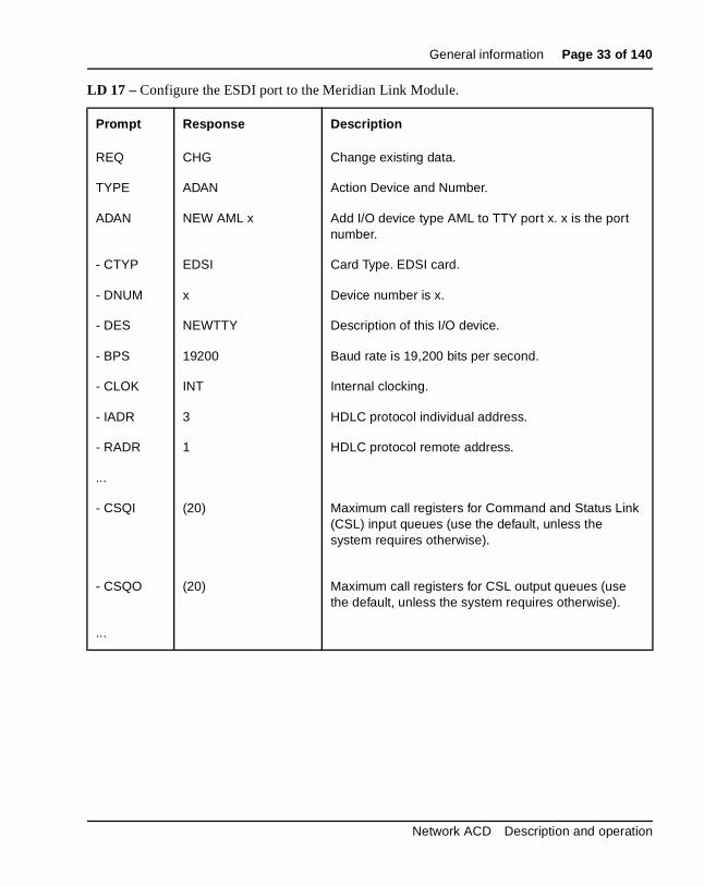
1 LD 17 – Configure the ESDI port to the Meridian Link Module.
2 LD 17 – Value added server ID.
3 LD 17 – Configure the MSDL port to the Meridian Link Module.
4 LD 17 – Value added server ID.
5 LD 10 – Configure non-ACD analog (500/2500 type) telephones as autodialers.
6 LD 11 – Configure non-ACD Meridian 1 proprietary telephones as autodialers.
7 LD 23 – Configure ACD groups.
8 LD 10 – Configure ACD analog (2500/500 type) telephones as autodialers.
9 LD 11 – Configure ACD Meridian 1 proprietary telephones as autodialers.
10 LD 23 – Configure a Control DN (CDN - default mode). If the application wants to transfer a call to a target CDN, a CDN must be configured. CDNs can be in default or controlled mode.
11 LD 23 – Configure a Control DN (CDN - controlled mode). When a CDN is in controlled mode, the application can have control of the conce it enters the CDN.
Network ACD Description and operation
Page 32 of 140 General information
ts
ed, o
r k.
m as
s
n be
is
ese
12 LD 14 – Define answer supervision for trunks. If the application wanto transfer outgoing calls based on answer supervision, answer supervision must be configured. If answer supervision is not configurthe End-of-Dialing timer will be used as a trigger for the Meridian 1 ttransfer the call.
13 LD 16 – If the application is using the End-of-Dialing timer to transfeoutbound calls, the timer must be configured in the Route Data Bloc
14 LD 17 – In order to originate calls from phantom TNs/DNs, a phantoloop must first be configured. A Phantom DN can then be configuredpart of a specific device group.
15 LD 97 – If a superloop is used, the phantom look is configured in thioverlay.
16 LD 11 – After configuring the phantom loop, an AST Meridian 1 proprietary set can be designated to a specific device group which cacontrolled by applications. Therefore, when an application wants to originate a call on behalf of an idle TN, it can use a phantom TN. Thidle TN is an AST Meridian 1 proprietary set which is defined on a phantom loop. The ITNA and DGRP prompts must be configured asfollows.
This feature does not require any changes to the overlays. The followingillustrates the configuration requirements to set up this feature. Most of threquirements are used by existing Meridian Link and Application Moduleapplication.
553-3671-120 Standard 10.00 April 2000
General information Page 33 of 140
LD 17 – Configure the ESDI port to the Meridian Link Module.
Prompt Response Description
REQ CHG Change existing data.
TYPE ADAN Action Device and Number.
ADAN NEW AML x Add I/O device type AML to TTY port x. x is the port number.
- CTYP EDSI Card Type. EDSI card.
- DNUM x Device number is x.
- DES NEWTTY Description of this I/O device.
- BPS 19200 Baud rate is 19,200 bits per second.
- CLOK INT Internal clocking.
- IADR 3 HDLC protocol individual address.
- RADR 1 HDLC protocol remote address.
...
- CSQI (20) Maximum call registers for Command and Status Link (CSL) input queues (use the default, unless the system requires otherwise).
- CSQO (20) Maximum call registers for CSL output queues (use the default, unless the system requires otherwise).
...
Network ACD Description and operation

Page 34 of 140 General information
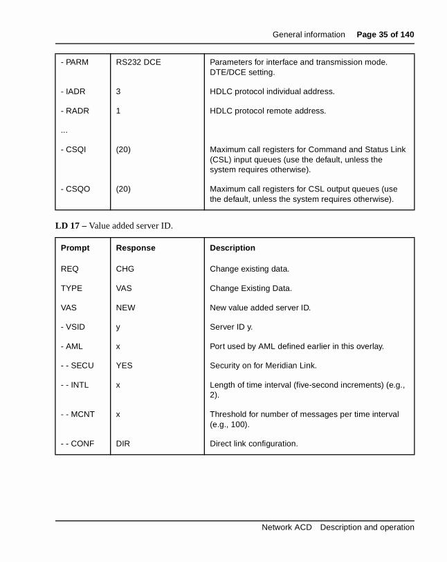
LD 17 – Value added server ID.
LD 17 – Configure the MSDL port to the Meridian Link Module.
Prompt Response Description
REQ CHG Change existing data.
TYPE VAS Change Existing Data.
VAS NEW New value added server ID.
- VSID y Server ID y.
- AML x Port used by AML defined earlier in this overlay.
- - SECU YES Security on for Meridian Link.
- - INTL x Length of time interval (five-second increments) (e.g., 2).
- - MCNT x Threshold for number of messages per time interval (e.g., 100).
- - CONF DIR Direct link configuration.
Prompt Response Description
REQ CHG Change existing data.
TYPE ADAN Action Device and Number.
ADAN NEW AML x Add I/O device type AML to TTY port x. x is the port number.
- CTYP MSDL Card Type. MSDL card.
- DNUM y Device number is y. Refers to the device number on the MSDL card.
- DES MERIDIAN_LINK Description of this I/O device.
- BPS 19200 Baud rate is 19,200 bits per second.
553-3671-120 Standard 10.00 April 2000
General information Page 35 of 140
LD 17 – Value added server ID.
- PARM RS232 DCE Parameters for interface and transmission mode. DTE/DCE setting.
- IADR 3 HDLC protocol individual address.
- RADR 1 HDLC protocol remote address.
...
- CSQI (20) Maximum call registers for Command and Status Link (CSL) input queues (use the default, unless the system requires otherwise).
- CSQO (20) Maximum call registers for CSL output queues (use the default, unless the system requires otherwise).
Prompt Response Description
REQ CHG Change existing data.
TYPE VAS Change Existing Data.
VAS NEW New value added server ID.
- VSID y Server ID y.
- AML x Port used by AML defined earlier in this overlay.
- - SECU YES Security on for Meridian Link.
- - INTL x Length of time interval (five-second increments) (e.g., 2).
- - MCNT x Threshold for number of messages per time interval (e.g., 100).
- - CONF DIR Direct link configuration.
Network ACD Description and operation
Page 36 of 140 General information
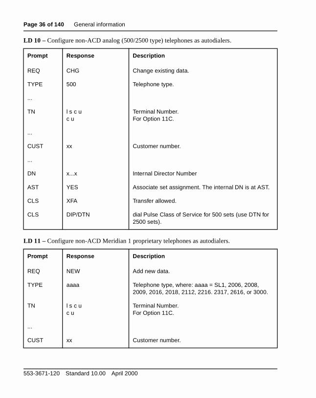
LD 10 – Configure non-ACD analog (500/2500 type) telephones as autodialers.
LD 11 – Configure non-ACD Meridian 1 proprietary telephones as autodialers.
Prompt Response Description
REQ CHG Change existing data.
TYPE 500 Telephone type.
...
TN l s c uc u
Terminal Number.For Option 11C.
...
CUST xx Customer number.
...
DN x...x Internal Director Number
AST YES Associate set assignment. The internal DN is at AST.
CLS XFA Transfer allowed.
CLS DIP/DTN dial Pulse Class of Service for 500 sets (use DTN for 2500 sets).
Prompt Response Description
REQ NEW Add new data.
TYPE aaaa Telephone type, where: aaaa = SL1, 2006, 2008, 2009, 2016, 2018, 2112, 2216. 2317, 2616, or 3000.
TN l s c u c u
Terminal Number.For Option 11C.
...
CUST xx Customer number.
553-3671-120 Standard 10.00 April 2000

General information Page 37 of 140
LD 23 – Configure ACD groups.
LD 10 – Configure ACD analog (2500/500 type) telephones as autodialers.
...
AST xx yy Key number for Associate set DN assignment.
...
KEY xx SCR yyyy Key number, Single Call Ringing, DN.
KEY xx TRN Key number, Call Transfer.
KEY xxx AO6 Key number, six-party conference.
KEY xxx SCR yyyy Key number, Single Call Ringing, second DN.
Prompt Response Description
REQ NEW Add new data.
TYPE ACD Automatic Call Distribution data block.
CUST xx Customer number.
ACDN xxxx ACD Directory Number.
xxx
ISAP YES Integrated Services Application Protocol. ACD DN uses Meridian Link (ISDN/AP) messaging.
- VSID 0-15 Value Added Server ID. This Server ID used for Meridian Link messaging must match the VSID defined in LD 17.
Prompt Response Description
REQ NEW Add new data.
TYPE 500 Telephone type.
Network ACD Description and operation
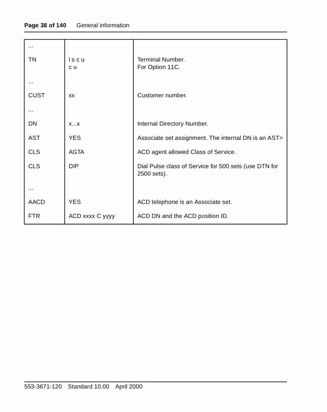
Page 38 of 140 General information
...
TN l s c u c u
Terminal Number.For Option 11C.
...
CUST xx Customer number.
...
DN x...x Internal Directory Number.
AST YES Associate set assignment. The internal DN is an AST>
CLS AGTA ACD agent allowed Class of Service.
CLS DIP Dial Pulse class of Service for 500 sets (use DTN for 2500 sets).
...
AACD YES ACD telephone is an Associate set.
FTR ACD xxxx C yyyy ACD DN and the ACD position ID.
553-3671-120 Standard 10.00 April 2000
General information Page 39 of 140
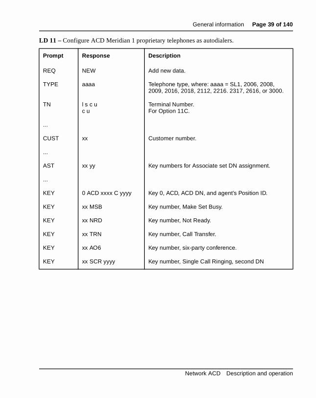
LD 11 – Configure ACD Meridian 1 proprietary telephones as autodialers.
Prompt Response Description
REQ NEW Add new data.
TYPE aaaa Telephone type, where: aaaa = SL1, 2006, 2008, 2009, 2016, 2018, 2112, 2216. 2317, 2616, or 3000.
TN l s c uc u
Terminal Number.For Option 11C.
...
CUST xx Customer number.
...
AST xx yy Key numbers for Associate set DN assignment.
...
KEY 0 ACD xxxx C yyyy Key 0, ACD, ACD DN, and agent’s Position ID.
KEY xx MSB Key number, Make Set Busy.
KEY xx NRD Key number, Not Ready.
KEY xx TRN Key number, Call Transfer.
KEY xx AO6 Key number, six-party conference.
KEY xx SCR yyyy Key number, Single Call Ringing, second DN
Network ACD Description and operation
Page 40 of 140 General information
call
LD 23 – Configure a Control DN (CDN - default mode). If the application wants to transfer a to a target CDN, a CDN must be configured. CDNs can be in default or controlled mode.Prompt Response Description
REQ NEW Add new data.
TYPE CDN Control Directory Number data block.
CUST xx Customer number.
CDN xxxx DN of the Control DN (counts as an ACD DN).
...
DFDN xxx...x Default destination ACD DN.
CEIL 0-(2047) CDN ceiling value. CEIL limits the number of unanswered calls a CDN can have as its default ACD DN at a time. Enter a maximum value (the default).
...
RPRT YES Report Control.
CNTL NO NO sends CDN calls to the Default ACD DN.
553-3671-120 Standard 10.00 April 2000
General information Page 41 of 140
e,
LD 23 – Configure a Control DN (CDN - controlled mode). When a CDN is in controlled modthe application can have control of the call once it enters the CDN.Prompt Response Description
REQ NEW Add new data.
TYPE CDN Control Director Number data block.
CUST xx Customer number.
CDN xxxx DN of the Control DN (counts as an ACD DN).
...
DFDN xxx...x Default destination ACD DN.
CEIL 0-(2047) CDN ceiling value. CEIL limits the number of unanswered calls a CDN can have as its default ACD DN at a time. Enter the maximum value (the default).
...
RPRT YES Report Control.
CNTL YES Control DN is in control (the default).
VSID 0-15 Value Added Server ID. Server ID used for Meridian Link messaging (defined in LD 17).
HSID 0-15 Host Line ID used when Customer Controlled Routing and Meridian Link applications are both running.
Network ACD Description and operation

Page 42 of 140 General information
alls is not call.
er
LD 14 – Define answer supervision for trunks. If the application wants to transfer outgoing cbased on answer supervision, answer supervision must be configured. If answer supervisionconfigured, the End-of-Dialing timer will be used as a trigger for the Meridian 1 to transfer the
LD 16 – If the application is using the End-of-Dialing timer to transfer outbound calls, the timmust be configured in the Route Data Block.
Prompt Response Description
REQ CHG Change existing data.
TYPE aaa Trunk type where: aaa = CAA, CAM, COT, CSA, DID, FEX, FGDT, IDA, TIE or WAT.
TN l s c u c u
Terminal Number.For Option 11C.
...
SUPN YES Answer and disconnect supervision are required.
Prompt Response Description
REQ CHG Change existing data.
TYPE RDB Route Data Block.
...
CNTL YES Change controls or timers.
- TIMR EOD 1281-(13952)-32640
End-of-Dialing timer in milliseconds. The default is 13952 milliseconds.
553-3671-120 Standard 10.00 April 2000
General information Page 43 of 140
LD 17 – In order to originate calls from phantom TNs/DNs, a phantom loop must first be configured. A Phantom DN can then be configured as part of a specific device group.
LD 97 – If a superloop is used, the phantom look is configured in this overlay.
Prompt Response Description
REQ CHG Change existing data.
TYPE CEQU Change to Common Equipment parameters.
...
- TERM 0-159 Single density local terminal loops.
(X) 0-159 Precede loop number with X to remove.
(N) 0-159 Precede loop number with N to create a phantom loop.
- TERD 0-159 Double density local terminal loops.
(X) 0-159 Precede loop number with X to remove.
(N) 0-159 Precede loop number with N to create a phantom loop.
- TERQ 0-159 Quad density local terminal loops.
(X) 0-159 Precede loop number with X to remove.
(N) 0-159 Precede loop number with N to create a phantom loop.
Prompt Response Description
REQ CHG Change existing data.
TYPE SUPL Superloop parameters.
SUPL 0-156 Superloop number in multiples of four.
(X) 0-156 Precede superloop number with X to remove.
(N) 0-156 Precede superloop number with N to create a phantom superloop.
Network ACD Description and operation
Page 44 of 140 General information
ated ation
AST ts
LD 11 – After configuring the phantom loop, an AST Meridian 1 proprietary set can be designto a specific device group which can be controlled by applications. Therefore, when an applicwants to originate a call on behalf of an idle TN, it can use a phantom TN. This idle TN is anMeridian 1 proprietary set which is defined on a phantom loop. The ITNA and DGRP prompmust be configured as follows.
Prompt Response Description
REQ NEW Add new data.
TYPE aaaa Telephone type, where: aaaa = 2006, 2008, 2009, 2016, 2018, 2112, 2216, 2317, 2616, or 3000.
TN l s c u c u
Terminal Number.For Option 11C.
...
CDEN Card density.
SD Single density.
DD Double density.
4D Quad density.
DES phanDN One-to-six character Office Data Administration system (ODAS) Station Designator.
CUST 0-99 Customer number.
...
CLS NDD No digit display is recommended if configuring phantom devices.
CLS (DNDD) Dialed Name Display denied is recommended if configuring phantom devices.
...
AST 00 Key 0 is AST.
553-3671-120 Standard 10.00 April 2000

General information Page 45 of 140
a
ncies
of the ty
Feature operationApplications invoke the Fast Transfer feature by sending the applicationFast Transfer request message to the switch. No specific operating instructions are required to use this feature.
Note: This section from “Meridian 911” on page 45 up to page 70 is only for North America.
Meridian 911The number 911 has been adopted for the purpose of reporting emergeand requesting emergency services. For localities with 911 systems, thenumber:
• is the same in all communities
• is easily remembered, even under adverse conditions, and
• provides direct telephone access to emergency services regardless time of day, or the caller’s familiarity with an area, or the caller’s abilito identify the type of emergency.
IAPG (0)-15 Meridian Link Unsolicited Status Message (USM) group. These groups determine which status messages are sent for an AST set. The default 0 sends no messages, whereas Group 1 sends all messages.
ITNA (NO), YES Idle TN for third-party application.
DGRP (1)-5 Device Group with which phantom TNs are associated.
...
KEY xx SCR yyyy Key number, Single Call Ringing, DN.
xx TRN Key number, Transfer.
xx RLS Key number, Release.
Network ACD Description and operation
Page 46 of 140 General information
s of fire, are st calls nce.
r to
s lice, to a . In cy for
911
g aling
of r
n the . ce and e
es.
A 911 system is planned, implemented, and operated under the auspicelocal governments. In most communities, 911 provides access to police, and emergency medical services. In some locations additional services accessible (e.g., dialing 911 in certain locations provides access to CoaGuard search and rescue services). Approximately 80 percent of all 911 are intended for the police, with the balance split between fire and ambula
Because the overwhelming majority of 911 calls require police attention,local police departments generally maintain, manage, and staff the centewhich emergency calls are first directed. These centers are referred to aprimary answering centers. A secondary answering center could be a pofire, or ambulance station (e.g., fire-related 911 calls may be transferredsecondary answering center that handles incoming calls regarding fires)many instances, the fire department also determines the degree of urgenemergency medical services.
If the primary or secondary answering center is busy or out of service, thecall is directed to a backup answering center, referred to as an alternateanswering center.
The public network routes a 911 call to the appropriate primary answerincenter based on the caller’s telephone number. for this reason, callers di911 give up their right to privacy regarding:
• the telephone number of the station from which they are calling, and
• the billing address associated with that telephone number.
To protect a caller’s right to privacy, some communities still allow the useseven-digit emergency numbers, routed either to an answering center odirectly to the responding agency.
Basic 911 serviceBasic 911 service routes emergency calls to an answering center based olocation of the Public Exchange/Central Office serving the calling stationThe jurisdiction of an answering center is determined by the Central Offiboundaries. The most basic 911 system involves only one Central Officeone exchange service area, and may be a single answering center. ForcDisconnect, and Idle Tone Application are examples of basic 911 featur
553-3671-120 Standard 10.00 April 2000

General information Page 47 of 140
tch cy
Office
g in
than
es cy
are
t of be
e d 911 te
Enhanced 911 serviceIn areas where telephone company Central Office boundaries do not majurisdictional boundaries, there is a problem in identifying which emergenagency should receive the emergency call. There may be an even morecomplicated situation if the 911 network includes two or more primary answering centers, and each serves areas that do not match the Central serving areas.
Enhanced 911 (E911) service ensures that an emergency call originatinany particular jurisdiction covered by the 911 system is recognized and forwarded to the appropriate responding agency in the same political jurisdiction as the originating call.
Enhanced 911 service uses more sophisticated equipment and featuresbasic 911 service. Specialized features include:
• Automatic Number Identification (ANI)
• Automatic Location Identifier (ALI), and
• Selective Routing (SR).
Display of the ANI associated with the originating call sometimes replacthe need for the following basic 911 options: Called Party Hold; EmergenRingback; and Switchhook Status. Therefore, sometimes these featuresnot provided with enhanced 911 service.
The Automatic Number Identification (ANI) of a 911 call consists of eighdigits (a Numbering Plan or Information digit followed by the seven digitsthe calling party number). Whether the first digit of the ANI string should interpreted as a Numbering Plan Digit (NPD) or an Information Digit (ID)depends on the trunk interface and Meridian 1 configuration.
The Automatic Location Identifier (ALI) host computer uses the ANI to locate the ALI record for the calling party number. This includes the namand address, and whether the line is business or residence. An enhancesystem creates ALI information from the ALI record and automatically routhe ALI information to an optional data terminal display at the answeringcenter.
Network ACD Description and operation
Page 48 of 140 General information
e s to
ns
re er
tes , but n
An enhanced 911 system routes all emergency calls from the originatingCentral Offices through an E911 Tandem, sometimes call a 911 control office, to the primary answering center. There, using Selective Routing features, a call taken can transfer the call through the public network by signaling the E911 Tandem. The Autodial Tandem transfer feature can bused for this. For example, if the primary answering center transfers callseveral fire departments, it uses one fire department button. The option automatically:
• identifies the fire department associated with caller’s location, and
• transfers the call to that department.
Meridian 911 systemThe Meridian 911 system:
• gives priority to emergency calls
• routes priority calls, without interrupting service, to answering positiothat can identify and dispatch the assistance required with minimumdelay
• displays the calling party’s number, and
• provides an external notification that an emergency call is queued.
When a call arrives at the Meridian 1 via an M911 trunk, the trunk softwain the Meridian 1 communicates with the serving Central Office (CO) (eiththe local Central Office or the M911 tandem office) to receive the ANI information via multifrequency (MF) signaling. When all ANI digits are received, the Meridian 1 software starts to process the call.
Meridian 911 Call AbandonA 911 call is considered abandoned by the Meridian 1 if the call terminaon a 911 trunk route, and the calling party disconnects after trunk seizurebefore the call is answered. This can occur while the call is waiting in anAutomatic Call Distribution (ACD) or Controlled DN (CDN) queue, or whethe call is presented to the ACD agent but is not yet answered.
553-3671-120 Standard 10.00 April 2000
General information Page 49 of 140
ll as the agent n on
c
n re
om
be , calls
ring ype)
The Call Abandon feature allows the Meridian 1 to treat an abandoned cathough the calling party is still connected. The call maintains its place in ACD queue, and is presented to an agent. When the agent answers, thereceives a continuous, cadenced six-second tone, as well as an indicatiothe set’s display, to indicate that the call is an abandoned call. AutomatiNumber Identification (ANI) information is also displayed. The agent canthen call back the originator of the call.
Once the call is abandoned, the trunk is released for other 911 calls. Information on abandoned calls can be included in Call Detail Recording(CDR) records if New Format CDR (FCDR) package 234 is equipped.
Operating parametersMeridian 911Meridian 911 routes are restricted to incoming traffic only.
Incoming M911 Trunks use MF signaling only. Dial Pulse (DP) and Dual-Tone Multifrequency (DTMF) are not supported for M911 routes.
911 Calls on Integrated Services Digital Network (ISDN) trunks are not supported.
A call is considered a 911 call by X11 software if it arrived on a trunk belonging to an M911 route. Calls dialing 911 internally can, through configuration of the Electronic Switched Network (ESN) digit manipulatiotables, be terminated locally (e.g., to a Controlled DN), but these calls ainternal calls to the software, not 911 calls.
ANI is expected for every call. Meridian 911 does not support 911 calls fran E911 Tandem which does not support sending ANI.
The priority of incoming trunk calls internally transferred to an AutomaticCall Distribution (ACD) DN queue (a secondary answering center) may preserved via blind transfer only. All other types of call modification (e.g.consultation transfer, or conference) are treated as internal calls and theare linked to the low priority queue of the ACD DN.
The No Hold Conference feature, the recommended feature for transfercalls between answering positions, is not available on analog (500/2500 tsets.
Network ACD Description and operation

Page 50 of 140 General information
, res d on
sed nnot DN, ged
nts ng re
e
is
lls. een ral
calls do
The Call Prioritization (911 calls being presented with higher priority, i.e.superceding business or non-911 calls) and Call Waiting Notification featuare applicable to ACD answering center only. These cannot be supporteMultiple Appearance Directory Number (MADN) answering centers.
The first answering center must be an ACD DN.
M911 trunk calls must terminate on a CDN. If an autoterminate DN is specified that is not a CDN, an SCH error message is printed. If a CDN is uas the autoterminate destination of at least one M911 trunk, the CDN cabe removed via LD 23 (an SCH message will be given). To remove the Call M911 trunks terminating to it must be removed, or they must be chanto terminate to a different CDN.
CDNs as well as ACD DNs are normal dialable numbers. Nothing prevenon-911 calls from arriving at either the CDN, or any of the ACD DNs actias answering centers via direct dialing. Non-911 calls arriving at CDNs adefaulted to the CDNs default ACD DN; non-911 calls arriving at an ACDDN are treated as normal calls.
The Call Waiting Notification (CWNT) package 225 is a separate packagand an M911 system can be installed without it. If the package is not equipped, no external alert can be given for 911 calls arriving at an ACDqueue.
The CWNT software is available for 911 calls in ACD queues only. Thereno provision for alerting MADN call takers of arriving 911 calls.
911 calls in an ACD queue are not treated any different from other ACD caTherefore, if Recorded Announcement (RAN) is configured for the ACDqueue, 911 calls will be given RAN treatment. The same interactions betwRAN and Central Office loopstart trunks exist for M911 as they do for geneACD operation.
Meridian 911 Call AbandonCalls released by the originator after the call has been answered are notabandoned by the definition used for the M911 Call Abandon feature andnot receive abandon treatment.
Abandoned calls waiting in the ACD queue activate the Call Waiting Notification Terminal Number.
553-3671-120 Standard 10.00 April 2000

General information Page 51 of 140
ince if
is
ible
the ith
AP)
11
oute
N
”
If ANI is not received, the abandoned call is not presented to the agent sit is no longer useful; however, a Call Detail Recording (CDR) N record, configured, can be printed to indicate that the call has abandoned.
Only external 911 calls abandoned before answer are supported.
When the call is abandoned, the speech path is dropped, and the trunk released.
If Flexible Tone and Cadences (FTC) package 125 is equipped, it is possto configure a tone other than the one provided by default.
Call Abandon is configured on a per route basis.
Call Abandon is supported on 911 trunks only.
No B record is generated by CDR for an M911 abandoned call, becauseB record is package dependent and only applies to an established call wInternal CDR.
Wireless sets are not supported at the Public Safety Answering Point (PSor Secondary Safety Answering Point (SSAP) for Call Abandon.
An MF tone receiver (QPC916 or NTAG20AA) is required.
Feature interactions (Meridian 911)Automatic Call Distribution InteractionsACD-C Reports—The Meridian 911 product does not change the ACD-Creports. M911 will use the ACD-C reports for CDNs as introduced for Customer Controlled Routing CCR in Release 17.
Only three of the fields in the report will have any meaning. Because M9uses the Route-to AML message instead of the Queue-to message, only“Route To”, “Default DN”, “Abandoned”, and “Calls Accepted” are meaningful. Those calls that are successfully routed count towards the “RTo” category. Those calls that get default treatment count towards the “Default DN” category. Those calls that abandon while they are in the CDqueue count towards the “Abandoned” category. The “Calls Accepted” category will be the sum of the “Route To”, “Default DN”, and “Abandonedcategories.
Network ACD Description and operation
Page 52 of 140 General information
tting
e
al
ile ue,
is ill,
ing
ll.
DN the s to the
The “# of Calls in the Queue” category represents those calls that are siin the CDN queue. This should always be zero, since calls waiting for a Route-to request from the Application Module are sitting in a timing queuas opposed to the CDN queue.
M911 calls routed to an ACD answering center will show up in the normACD Queue and agent reports for that queue. Calls routed to MADN answering centers will show up only in the CDN report.
ACD-D Auxiliary MessageNo changes to the ACD-D reports are needed for Meridian 911.
Controlled Director Number (CDN) CeilingThe CDN ceiling feature returns busy tone to calls arriving at the CDN whit is in default mode. Should a 911 call arrive while these conditions are trthe 911 call will not hear busy tone, but will be linked into the default destination ACD DN’s queue. Therefore, the setting of the ceiling value irrelevant if only 911 calls are expected at the CDN. The ceiling value whowever, still be applied to non-911 calls arriving at the CDN.
Controlled Director Number (CDN) Ringback – 911 Calls get ringback immediately upon arrival at a CDN, whereas CCR calls do not.
Custom Call Routing (CCR) Call Abandoned Message (ICAB)This message is sent for controlled calls that were abandoned before beanswered.
Custom Call Routing (CCR) Call Enters Queue Message (ICEQ)This message is sent to ACD-CCR each time a default call is placed in thedefault ACD DN (default mode).
Custom Call Routing (CCR) Call Modification Message (ICCM)This message is sent to ACD-CCR when a call modification request (route to, disconnect, busy) is successfully executed upon a CDN controlled ca
Note that since the Rout To, Disconnect and Busy treatments remove Ccontrol from the call, ICCM messages will be sent for the call for each of queues from where it must be removed. The ICCM message also applieEnhanced ACD Routing calls or CDN default calls which were busied by call ceiling value while trying to route to the default ACD-DN.
553-3671-120 Standard 10.00 April 2000
General information Page 53 of 140
the s
14
e,
re ot a
. If t
ith D g
ls.
Custom Call Routing (CCR) “Route To” CommandThe Route to destination for 911 calls are restricted to ACD DNs only. If routing destination is not an ACD DN, the call will be routed to the CDN’default destination ACD DN. CCR calls can be routed to any dialable number.
Enhanced ACD Routing/Customer Controlled RoutingThe Enhanced ACD Routing/Customer Controlled Routing (EAR/CCR) features introduce CDNs. The Enhanced ACD routing (EAR) package 2allows CDNs to be configured and is a prerequisite of the Meridian 911 (M911) package 224.
Interflow911 Calls interflow just like any other ACD calls. If the interflow feature isconfigured so that a call gets busy tone, the 911 call will not get busy tonbut will instead be linked back into the source ACD queue.
If the interflow destination is a number outside the Meridian 1, the softwahas no control over the treatment the call gets, so this configuration is nrecommended operation for 911 sites.
Load Management CommandsNo changes are made to Load Management for Meridian 911.
Night ServiceNight Call ForwardIt is recommended that the primary ACD DN not be put in Night Servicethe primary ACD DN is put in Night Service, calls will be sent to the NighCall Forward (NCFW) destination. Even if a 911 call arrived on a trunk wCPDC defined, the call will still be allowed to NCFW, unlike non-911 ACcalls. This restriction is lifted for 911 calls only. The CWNT set will not rinfor calls entering the queue while in Night Service when the queue has aNCFW destination specified.
Overflow911 Calls will overflow (by count and by time) just like any other ACD cal
Network ACD Description and operation
Page 54 of 140 General information
s.
k ture
d
play
(the by
e
Supervisor Control of Queue SizeThis feature causes calls to get busy tone once the overflow threshold (OVTH) of the ACD queue is exceeded. This feature is bypassed for 911calls.
Call Detail Recording (CDR) RecordsANI for 911 calls is included as the Calling Line Identification (CLID) in CDR Records pertaining to 911-trunk calls. CDR Records affected are: Normal Records, Start/End Records, Authorization Code Records, Connection Records (Q, R, and F records), and Charge Account Record
Called Party Disconnect ControlThe Called Party Disconnect (CPDC) feature is used to retain a 911 trunwhen a 911 call is disconnected by the caller. No modification to the feais required for Meridian 911, except lifting the CPDC and ACD NCFW limitation. 911 Calls, arriving via trunks with CPDC defined, will be alloweto NCFW, unlike non-911 ACD calls.
Calling Party Name DisplayThe Calling Party Name Display feature can be used to configure and disthe incoming 911 route name.
ConferenceWhen a call is answered, and then conferenced, the trunk priority is lost conference consultation call is an internal call and treated as low prioritythe software). This operation is the same for normal calls and 911 calls.
Dialed Number Identification Service (DNIS)DNIS is not supported on 911 trunks.
Integrated Services Digital Network (ISDN) Basic Rate Interface (BRI)Answering Positions are not supported on BRI sets.
Integrated Services Digital Network (ISDN) Primary Rate Interface911 Trunks are not supported On ISDN PRI Trunks or Integrated ServicLink (ISL) trunks.
553-3671-120 Standard 10.00 April 2000

General information Page 55 of 140
D C a
the
ingle ime. t DN
ker re e new
nd
eak-In
Japan Direct Inward Dialing (DID) TrunksJapan DID trunks are not supported.
Malicious Call TraceThe Malicious Call Trace (MCT) feature is modified to be supported on ACsets. ACD sets are allowed to have the MCTA Class of Service and a TRkey defined. The feature is activated via pressing the MCT key or dialingMCT access code.
No Hold ConferenceNo Hold Conference calls are treated as internal calls and are linked to low priority queue of the ACD DN.
Single and Multiple Call Ringing for MADNsThe DN keys for multiple appearance sets can be defined as an SCR (scall ringing) key or as an MCR (multiple call ringing) key. For those DNs(keys on MADN sets) that are SCR, only one call may be answered at a tThat is to say that once a call taker has answered a call, future calls to thawill receive busy tone until the call taken on that DN has disconnected.
For DNs that are MCR, calls will only be given bust tone once every call tais busy answering a call. If one call taker is answering a call and there aother call takers available, a new call to that DN will cause the sets of thavailable call takers to ring. Any available call taker can then answer the call.
TransferTrunk priority associated with an incoming 911 call is only preserved if blitransfer is used.
Feature interaction (Meridian 911 Call Abandon)Attendant Break-InSince an abandoned call does not have a speech path established, the Brdeny treatment is given to the attendant so that Break-In cannot occur.
Automatic Call Distribution (ACD)When a call is abandoned, the call remains in its current state (i.e., ACDqueue, CDN queue, or ringing on an ACD agent set).
Network ACD Description and operation

Page 56 of 140 General information
ned n the
s; ,
er al ent
. The the
ls g up call
ay. ver, e is
ect
Automatic Call Distribution ReportsACD-C and ACD-D packages are not modified for M911 Call Abandon. However, a new interpretation for the report fields are needed for abandocalls. The incoming call is pegged as an abandoned call when the callerabandons. However, it is not repeatedly pegged as an answered call whecall taker answers the abandoned call.
For ACD-C package, the CALLS ANSWD field only accounts for real callthe ABANDONED field accounts for abandoned calls that are answeredassuming all abandoned calls are eventually answered by an agent. Consequently, the CALLS ACCPTD field is equal to the CALLS ANSWDfield plus the ABANDONED field (number of calls entering queue = numbof real calls + number of abandoned ones). This way the Average or TotCall Processing (DCP) Time accurately reflects the amount of time an agspent on real calls, since answering an abandoned call requires little timework an agent does for an abandoned call is more accurately reflected inDN OUT and OUT TIME fields, which mean total number of outgoing caland total time of all outgoing calls respectively. Since the agent must hanthe abandoned call and call back to see what the condition is, the outgoingthat is made is more valuable for reporting the agent’s work.
For the ACD-D package, the reports also need to be interpreted in this wWhen the caller abandons, CAB message is sent to Meridian MAX; howelater when an abandoned call is answered by an agent no CAA messagsent to Meridian MAX.
Call ForceM911 abandoned calls cannot be call forced.
Called Party Disconnect ControlThere is no interaction with M911 Call Abandon and Called Party DisconnControl.
ConferenceM911 abandoned calls cannot be conferenced.
553-3671-120 Standard 10.00 April 2000

General information Page 57 of 140
ht t
calls
t
the Not on
Display Calls Waiting KeyACD Calls Waiting KeyOngoing Status DisplayReal-time DisplayIn all of these situations, abandoned calls contribute to the queue count.
HoldM911 abandoned calls cannot be put on hold.
InitializationUnanswered abandoned calls are lost if the system initializes.
InterflowAbandoned calls contribute to the queue count. An abandoned call can interflow only the ACD DNs.
Network ACDNetwork ACD is not supported.
Night Call Forward (NCFW)Abandoned calls can be forwarded to the Night Call Forward DN if the NigForward DN is an ACD DN. If a primary answering center goes into NighService while there are abandoned calls in the queue, those abandonedare dropped. A CDR N record is printed if CDR is configured.
Night Service KeyAbandoned calls are part of the transition mode when agents go to NighService and the supervisor selects transition mode.
No Hold ConferenceM911 abandoned calls cannot be No Hold conferenced.
Not Ready KeyWhen an abandoned call is presented to an agent and the agent presses Ready Key, the call is put back into the queue. If an agent is establishedan abandoned call and presses the Not Ready Key, the call is dropped.
Network ACD Description and operation
Page 58 of 140 General information
e the ear
d:
ll
ed
Overflow by CountAbandoned calls contribute to the queue count. An abandoned call can overflow.
Supervisor ObserveSince there is no speech path between the ACD agent and the caller, thsupervisor observe feature will be blocked. The supervisor can still pressobserve key to observe an agent active on an abandoned call, but will hsilence.
TransferM911 abandoned calls cannot be transferred.
Feature packagingThe following packages are required:
• Digits Automatic Call Distribution (DDSP) package 19
• Basic Automatic Call Distribution (BACD) package 40
• Automatic Call Distribution Package B (ACDB) package 41
• Automatic Call Distribution Package A (ACDA) package 45
• Enhanced Automatic Call Distribution Routing (EAR) package 214
• Meridian 911 (M911) package 224, and
• Call Waiting Notification (CWNT) package 225.
The following additional packages are not required, but are recommende
• At least one of either Call Detail Recording (CDR) package 4, or CaDetail Recording on Teletype Machine (CTY) package 5
• Automatic Call Distribution Package C (ACDC) package 42 (not needif packages 51 and 52 are enabled)
• Automatic Call Distribution Load Management Reports (LMAN) package 43
• Automatic Call distribution Package D (ACDD) package 50
• Automatic Call Distribution Package D, Auxiliary Link Processor (LNK) package 51
553-3671-120 Standard 10.00 April 2000
General information Page 59 of 140
ge
he 11
set .
o lls
en ne.
if
• Call Party Name Display (CPND) package 95
• Malicious Call Trace (MCT) package 107, and
• Calling Line Identification in Call Detail Recording (CCDR) package 118.
The M911 Call Abandon feature is included in Meridian 911 (M911) packa224, and required Call Identification (CALL ID) package 247.
If an application also involves Meridian Link, Meridian Link Module (MLM)package 209 is required.
Feature implementationTask summary list
This section provides an example of how to configure Meridian 911. Theorder in which all items must be configured, in order for M911 to run on tMeridian 1, is outlined. In addition, the implementation procedures for M9Call Abandon are shown.
1 LD 10 – Configure a Terminal Number for an analog (500/2500 type) with a Class of Service of Call Waiting Notification Allowed (CWNA)
2 LD 23 – Configure ACD DNs. The CWNC control is recommended tbe set as YES for the primary answering centers (rings for priority caonly) and NO for secondary answering centers (rings for all calls).
3 LD 23 – Configure CDNs. The ceiling value is irrelevant for 911 callsterminating at the CDN, but will be applied to non-911 type calls. Whthe ceiling value is exceeded, new non-911 calls will receive busy to
4 LD 16 – Configure NPID tables.
5 LD 16 – Configure an M911 route.
6 LD 14 – Configure M911 trunks.
7 LD 16 – Configure Call Detail Recording (CDR).
8 LD 17 – Configure the insertion of ANI digits into the CDR record.
9 LD 16 – Enable M911 Call Abandon (optional).
10 LD 56 – Configure the new flexible tone for M911 abandoned calls, desired.
Network ACD Description and operation
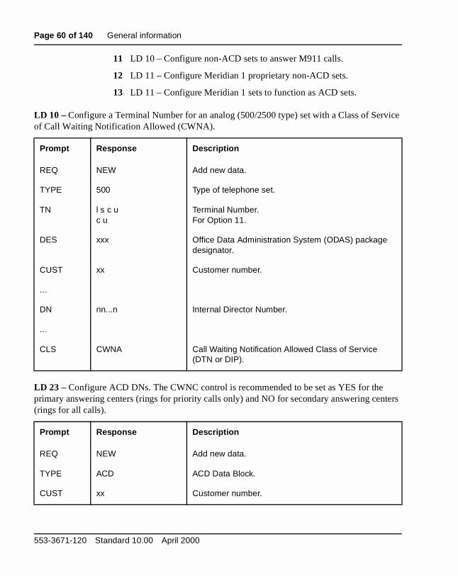
Page 60 of 140 General information
rvice
nters
11 LD 10 – Configure non-ACD sets to answer M911 calls.
12 LD 11 – Configure Meridian 1 proprietary non-ACD sets.
13 LD 11 – Configure Meridian 1 sets to function as ACD sets.
LD 10 – Configure a Terminal Number for an analog (500/2500 type) set with a Class of Seof Call Waiting Notification Allowed (CWNA).
LD 23 – Configure ACD DNs. The CWNC control is recommended to be set as YES for theprimary answering centers (rings for priority calls only) and NO for secondary answering ce(rings for all calls).
Prompt Response Description
REQ NEW Add new data.
TYPE 500 Type of telephone set.
TN l s c uc u
Terminal Number.For Option 11.
DES xxx Office Data Administration System (ODAS) package designator.
CUST xx Customer number.
...
DN nn...n Internal Director Number.
...
CLS CWNA Call Waiting Notification Allowed Class of Service (DTN or DIP).
Prompt Response Description
REQ NEW Add new data.
TYPE ACD ACD Data Block.
CUST xx Customer number.
553-3671-120 Standard 10.00 April 2000
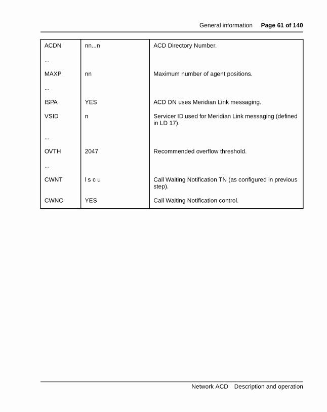
General information Page 61 of 140
ACDN nn...n ACD Directory Number.
...
MAXP nn Maximum number of agent positions.
...
ISPA YES ACD DN uses Meridian Link messaging.
VSID n Servicer ID used for Meridian Link messaging (defined in LD 17).
...
OVTH 2047 Recommended overflow threshold.
...
CWNT l s c u Call Waiting Notification TN (as configured in previous step).
CWNC YES Call Waiting Notification control.
Network ACD Description and operation
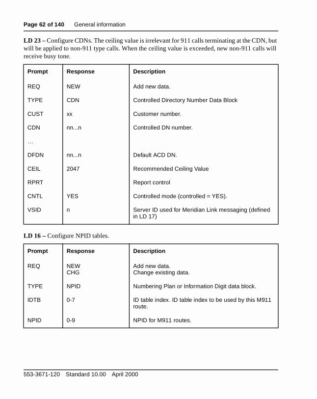
Page 62 of 140 General information
but s will
LD 23 – Configure CDNs. The ceiling value is irrelevant for 911 calls terminating at the CDN,will be applied to non-911 type calls. When the ceiling value is exceeded, new non-911 callreceive busy tone.
LD 16 – Configure NPID tables.
Prompt Response Description
REQ NEW Add new data.
TYPE CDN Controlled Directory Number Data Block
CUST xx Customer number.
CDN nn...n Controlled DN number.
…
DFDN nn...n Default ACD DN.
CEIL 2047 Recommended Ceiling Value
RPRT Report control
CNTL YES Controlled mode (controlled = YES).
VSID n Server ID used for Meridian Link messaging (defined in LD 17)
Prompt Response Description
REQ NEWCHG
Add new data.Change existing data.
TYPE NPID Numbering Plan or Information Digit data block.
IDTB 0-7 ID table index. ID table index to be used by this M911 route.
NPID 0-9 NPID for M911 routes.
553-3671-120 Standard 10.00 April 2000
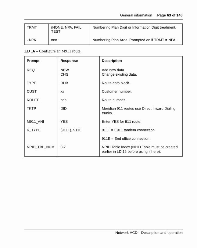
General information Page 63 of 140
LD 16 – Configure an M911 route.
TRMT (NONE, NPA, FAIL, TEST
Numbering Plan Digit or Information Digit treatment.
- NPA nnn Numbering Plan Area. Prompted on if TRMT = NPA.
Prompt Response Description
REQ NEWCHG
Add new data.Change existing data.
TYPE RDB Route data block.
CUST xx Customer number.
ROUTE nnn Route number.
TKTP DID Meridian 911 routes use Direct Inward Dialing trunks.
M911_ANI YES Enter YES for 911 route.
K_TYPE (911T), 911E 911T = E911 tandem connection
911E = End office connection.
NPID_TBL_NUM 0-7 NPID Table Index (NPID Table must be created earlier in LD 16 before using it here).
Network ACD Description and operation
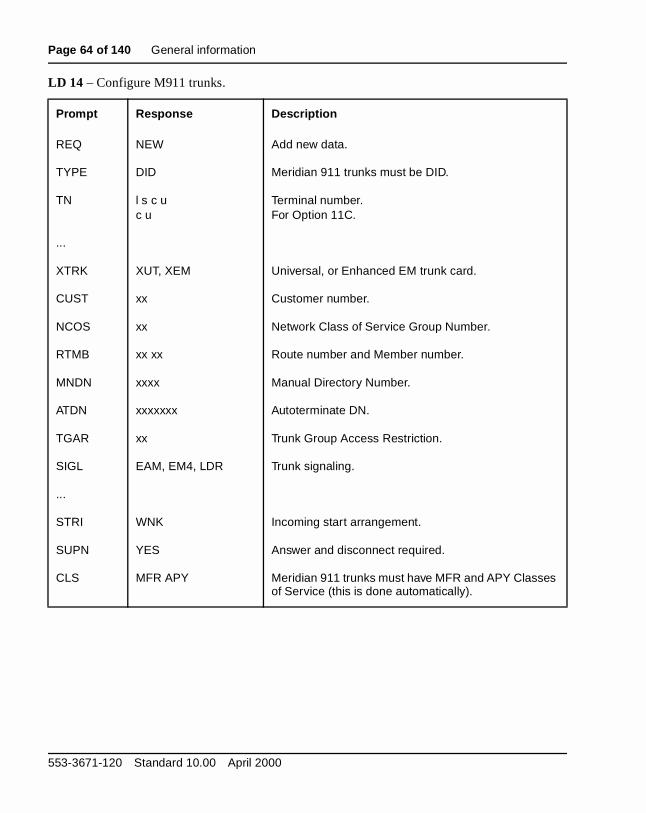
Page 64 of 140 General information
LD 14 – Configure M911 trunks.
Prompt Response Description
REQ NEW Add new data.
TYPE DID Meridian 911 trunks must be DID.
TN l s c u c u
Terminal number.For Option 11C.
...
XTRK XUT, XEM Universal, or Enhanced EM trunk card.
CUST xx Customer number.
NCOS xx Network Class of Service Group Number.
RTMB xx xx Route number and Member number.
MNDN xxxx Manual Directory Number.
ATDN xxxxxxx Autoterminate DN.
TGAR xx Trunk Group Access Restriction.
SIGL EAM, EM4, LDR Trunk signaling.
...
STRI WNK Incoming start arrangement.
SUPN YES Answer and disconnect required.
CLS MFR APY Meridian 911 trunks must have MFR and APY Classes of Service (this is done automatically).
553-3671-120 Standard 10.00 April 2000
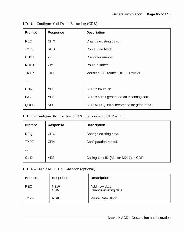
General information Page 65 of 140
LD 16 – Configure Call Detail Recording (CDR).
LD 17 – Configure the insertion of ANI digits into the CDR record.
LD 16 – Enable M911 Call Abandon (optional).
Prompt Response Description
REQ CHG Change existing data.
TYPE RDB Route data block.
CUST xx Customer number.
ROUTE xxx Route number.
TKTP DID Meridian 911 routes use DID trunks.
...
CDR YES CDR trunk route.
INC YES CDR records generated on incoming calls.
QREC NO CDR ACD Q initial records to be generated.
Prompt Response Description
REQ CHG Change existing data.
TYPE CFN Configuration record.
...
CLID YES Calling Line ID (ANI for M911) in CDR.
Prompt Response Description
REQ NEWCHG
Add new data.Change existing data.
TYPE RDB Route Data Block.
Network ACD Description and operation
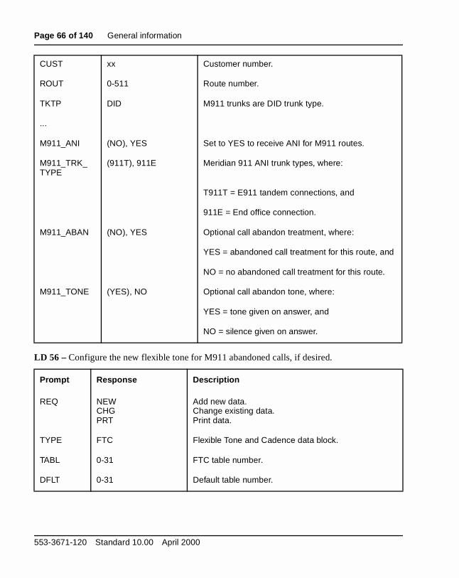
Page 66 of 140 General information
LD 56 – Configure the new flexible tone for M911 abandoned calls, if desired.
CUST xx Customer number.
ROUT 0-511 Route number.
TKTP DID M911 trunks are DID trunk type.
...
M911_ANI (NO), YES Set to YES to receive ANI for M911 routes.
M911_TRK_TYPE
(911T), 911E Meridian 911 ANI trunk types, where:
T911T = E911 tandem connections, and
911E = End office connection.
M911_ABAN (NO), YES Optional call abandon treatment, where:
YES = abandoned call treatment for this route, and
NO = no abandoned call treatment for this route.
M911_TONE (YES), NO Optional call abandon tone, where:
YES = tone given on answer, and
NO = silence given on answer.
Prompt Response Description
REQ NEWCHGPRT
Add new data.Change existing data.Print data.
TYPE FTC Flexible Tone and Cadence data block.
TABL 0-31 FTC table number.
DFLT 0-31 Default table number.
553-3671-120 Standard 10.00 April 2000
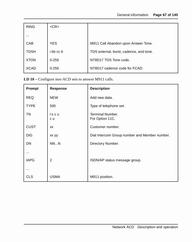
General information Page 67 of 140
LD 10 – Configure non-ACD sets to answer M911 calls.
RING <CR>
...
CAB YES M911 Call Abandon upon Answer Tone.
TDSH i bb cc tt TDS external, burst, cadence, and tone.
XTON 0-255 NT8D17 TDS Tone code.
XCAD 0-255 NT8D17 cadence code for FCAD.
Prompt Response Description
REQ NEW Add new data.
TYPE 500 Type of telephone set.
TN l s c u c u
Terminal Number.For Option 11C.
CUST xx Customer number.
DIG xx yy Dial Intercom Group number and Member number.
DN NN...N Directory Number.
...
IAPG 2 ISDN/AP status message group.
...
CLS USMA M911 position.
Network ACD Description and operation

Page 68 of 140 General information
LD 11 – Configure Meridian 1 proprietary non-ACD sets.
LD 11 – Configure Meridian 1 sets to function as ACD sets.
Prompt Response Description
REQ NEW Add new data.
TYPE aaaa Telephone type, where: aaaa = SL1, 2006, 2008, 2009, 2018, 2112, 2216, 2317. 2616, and 3000.
TN l s c u c u
Terminal Number.For Option 11C.
DES x...x ODAS set designator.
CUST xx Customer number.
...
CLS USMA MCTA M911 position; Malicious Call Trace allowed.
...
IAPG 2 ISDN/AP status message group.
...
KEY xx SCR yyyy This defines a Single Call Ringing DN key.
KEY xx TRC Malicious Call Trace key.
Prompt Response Description
REQ NEW Add new data.
TYPE aaaa Telephone type, where: aaaa = SL1, 2006, 2008, 2009, 2018, 2112, 2216, 2317. 2616, and 3000.
TN l s c u c u
Terminal Number.For Option 11C.
DES x...x ODAS set designator.
553-3671-120 Standard 10.00 April 2000

General information Page 69 of 140
hat is ey.
CD
call y if
r’s ed.
Feature operationMeridian 911 operationTo answer a call at a primary, secondary, or alternate answering center tconfigured with ACD positions, the 911 call taker presses the ACD DN kThe DN of the incoming call is displayed on the call taker’s set.
Meridian 911 Call abandon operationWhen the call is abandoned it remains in its current state (i.e., in CDN or Aqueue or ringing a call taker). Once the call taker answers, a continuouscadenced tone is heard for six seconds, followed by silence. This tone isprogrammable with the FTC package; otherwise, a default is given. Thetaker must hang up and dial the ANI that is shown on the terminal displacall back is required.
Upon answer, the telephone set display is updated with the 911 call takeANI and the trunk group name if the Call Party Name Display feature is usSince the call has been abandoned, the telephone set display flags the abandoned call by appending “ABAND” to the ANI.
CUST xx Customer number.
...
CLS ADD AGN USMA MCTA
AGN is for agent; SPV is for supervisor. USMA = 911 position, and MCTA = Malicious Call Trace allowed.
...
IAPG 2 ISDN/AP status message group.
...
KEY 0 ACD yyyy C zzzz The ACD DN key where yyyy is the ACD DN and zzzz is the position ID.
KEY xx TRC Malicious Call Trace key. The xx is the key number.
Network ACD Description and operation
Page 70 of 140 General information
a ty first
the
.
tion allow and odes ected
tion. hese plits e
The following example shows what is displayed on a telephone set with Numbering Plan Digit (NPD) call with an NPD of 2 and with the Call ParName Display feature enabled. The trunk group name is displayed on theline of the set display; the ANI appears on the second line.
911 CALL2 493-6002 ABAND
DP of 1 that was translated to 415 and has the Call Party Name Displayfeature enabled. The trunk group name (e.g., Palo Alto) is displayed on first line of the set display. The ANI appears on the second line.
Palo Alto415 493-6002 ABAND
ISDN overviewIntegrated Service Digital Networks (ISDN) use a standard protocol to transport both call-related and non-call-related messages to other nodes
Network ACD uses ISDN D-channel messages to transport call informabetween the Source node and the remote Target queues. ISDN servicesthe messaging between nodes required for Call Requests, cancellation,set-up messaging described later in this document. Source and Target ncan be connected through tandem switches; they do not need to be connpoint-to-point.
Primary Rate Interface (PRI)The ISDN PRI architecture is composed of protocol layers providing different services. There are three supporting layers:
These layers provide a standard interface for voice and data communicaEach layer uses the services provided by the layer below, and builds on tservices to perform functions for the layer above. This layered approach scomplex protocols into easily managed blocks. Each layer or block can bmodified without affecting the protocols in another layer.
Layer 1 Physical layer
Layer 2 Link layer
Layer 3 Network layer
553-3671-120 Standard 10.00 April 2000
General information Page 71 of 140
he
n.
d
1
red s,
ns
ls ent
D-channelWithin an ISDN environment, call control is supported out-of-band over tD-channel. The D-channel transports call control information.
Each D-channel can support up to 383 B-channels for voice transmissioEach system can support up to eight D-channels. For installation and engineering details, be sure to review “ISDN” on page 72.
ISDN Signaling Link (ISL)ISDN Signaling Link (ISL) provides the capability to replace both digital ananalog conventional trunk signaling with out-of-band ISDN D-channel signaling. ISL supports tie and ISA trunk types with Meridian 1 to Meridianconnectivity.
There are two modes of ISL operation:
• Shared mode This configuration is basically the same as the PRI D-channel also supporting ISL trunks.
• Dedicated mode The D-channel interface is reserved for ISL use.
An ISA route must be established and identified with the dedicated or shaISL interface. For a complete description of the ISL operating parameterrefer to the X11 Networking Features and Services (553-2901-301).
Supporting documentsNetwork ACD (NACD) uses more than one special feature from the X11software packages. You should have all of the ISDN and ACD publicatiorelative to your application environment.
ACD Automatic Call Distribution (ACD) allows a large number of incoming calto the same directory number (called the ACD DN) to be answered at agpositions that share the influx of calls equally. The Automatic Call Distribution system is fully described in these documents:
• Automatic Call Distribution: Feature Description (553-2671-110)
• Automatic Call Distribution: Management Commands and Reports (553-2671-112)
Network ACD Description and operation
Page 72 of 140 General information
ed
ents .
ISDNNetwork ACD is dependent on the network services and transport providby ISDN. The ISDN network should already be up and running before loading the NACD package. Therefore, you should already have the following publications on hand:
• ISDN Primary Rate Interface Feature description and administration
• ISDN Primary Rate Interface Installation
• ISDN Primary Rate Interface Maintenance
System support documentsNACD requires that the system have a specific configuration. The documlisted here provide background information supporting that configuration
Dialing Plans
• Automatic Number Identification feature module in X11 Features and Services (553-3001-306)
• Basic and Network Alternate Route Selection: Description (553-2751-100)
• Coordinated Dialing Plan: Description (553-2751-102)
Electronic Switched Networks (ESN)
• Electronic Switched Network Signaling Guidelines (309-3001-180)
• Electronic Switched Network Transmission Guidelines (309-3001-181)
553-3671-120 Standard 10.00 April 2000
Page 73 of 140
96
NACD Functional descriptionContent list
The following are the topics in this section:
• Reference list 74
• Network environment 74
• Routing Tables 75
• Source Table Viewer 78
• Cascade routing 81
• Dynamic status change 83
• Incoming calls 84
• Call Requests 84
• Canceling Call Requests 85
• Queue priorities 86
• Call presentation 87
• Feature interactions 88
• ACD interactions 88
• Feature interactions 96
Network ACD Description and operation
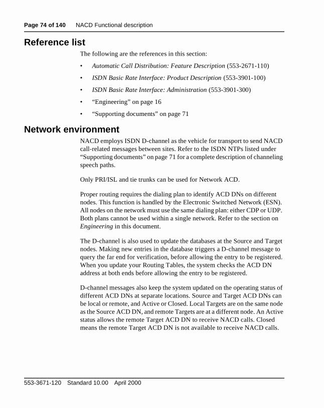
Page 74 of 140 NACD Functional description
D er ling
N). DP. on
arget e to
ed.
tus of an
node ctive s.
Reference listThe following are the references in this section:
• Automatic Call Distribution: Feature Description (553-2671-110)
• ISDN Basic Rate Interface: Product Description (553-3901-100)
• ISDN Basic Rate Interface: Administration (553-3901-300)
• “Engineering” on page 16
• “Supporting documents” on page 71
Network environmentNACD employs ISDN D-channel as the vehicle for transport to send NACcall-related messages between sites. Refer to the ISDN NTPs listed und“Supporting documents” on page 71 for a complete description of channespeech paths.
Only PRI/ISL and tie trunks can be used for Network ACD.
Proper routing requires the dialing plan to identify ACD DNs on differentnodes. This function is handled by the Electronic Switched Network (ESAll nodes on the network must use the same dialing plan: either CDP or UBoth plans cannot be used within a single network. Refer to the section Engineering in this document.
The D-channel is also used to update the databases at the Source and Tnodes. Making new entries in the database triggers a D-channel messagquery the far end for verification, before allowing the entry to be registerWhen you update your Routing Tables, the system checks the ACD DNaddress at both ends before allowing the entry to be registered.
D-channel messages also keep the system updated on the operating stadifferent ACD DNs at separate locations. Source and Target ACD DNs cbe local or remote, and Active or Closed. Local Targets are on the same as the Source ACD DN, and remote Targets are at a different node. An Astatus allows the remote Target ACD DN to receive NACD calls. Closedmeans the remote Target ACD DN is not available to receive NACD call
553-3671-120 Standard 10.00 April 2000
NACD Functional description Page 75 of 140
e .
rget ated rget. ally ame,
to ach 0 CD ets
are es hen
ts in ) e s as
Routing TablesThe ACD DN at a Source node is called the Source ACD DN. The SourcACD DN is always used for routing ISDN messages over the D-channel
Targets in each table are put in order by the system according to the Tatimer value, from the lowest value to the highest value. The timer associwith each Target is used to decide when to issue a Call Request to that TaThe table entries can be entered in any order, and the table is automaticreordered when timer values are changed. If all the timer values are the sthe entries are listed in the order they are entered.
Network ACD uses Routing Tables for the Source ACD DN to direct callspotential Target ACD DNs. Up to 20 different Targets can be defined for eSource ACD DN. Each Target can have an individual timer defined, fromto 1800 seconds. Each entry in the Routing Tables includes the Target ADN, an associated timer, and status information for the Target. The Targin each routing table can be either local or remote.
The Routing Table information is used to determine when and where callsdiverted from the Source ACD DN to Target ACD DNs. There are two typof Routing Tables: Day Tables and Night Tables. The Day Table is used wthe Source ACD DN is in Day mode. The Night Table is used when the Source ACD DN is in Night mode.
Calls not allowed to be diverted by NACD are listed here:
• calls with ACD Ring Again activated
• Call Park Recall calls
• calls active in Teleset Messaging
• calls without Disconnect Supervision
Day TablesThe Day Table is used when the Source ACD DN is in Day mode. Targethe Day Table are used independent of the Overflow by Number (OVDNtargets. They can be the same Targets, but they must be redefined in thRouting Table. If no Day Table is defined, then TOF (if enabled) operateusual.
Network ACD Description and operation

Page 76 of 140 NACD Functional description
call TOF rget
ee
the de.
able t
oad t
When a call exceeds the defined timer for a Target in the Day Table, theremains in the originating queue, and a Call Request is sent to the Targetqueue. If the call has overflowed by number to a Target node, and the Tatimer expires, the call is returned to the Source TOF queue.
These calls are not allowed to access the Day Table:
• Call Park Recalls
• ACD Ring Again calls
• virtual calls (CCR, IVR)
While the ACD DN with a call is in Day Service, the call is monitored to sif it exceeds any other related timers.
Night TableThe Night Table provides another night treatment that can be defined forsystem. The Night Table is only accessed when an ACD DN is in Night mo
When the Source ACD DN is in Night mode, the call accesses the Night Tfor that ACD DN queue. If there is no Night Table defined, then the NighCall Forward (NCFW) DN is used, if it is enabled.
These calls cannot access the Night Table:
• calls with outstanding Call Requests in the Day Table
• Call Park Recalls
• ACD Ring Again calls
• callers active in Teleset Messaging
If the Night Table is defined, then Night Call Forward (NCFW) does not apply. An error message is output if anyone uses the NITE command in LManagement. Also, the NCFW prompt will not appear in LD 23 if a NighTable is defined.
553-3671-120 Standard 10.00 April 2000

NACD Functional description Page 77 of 140
call t is ted
the
ore
is ) that ll is
When a call exceeds the defined timer for a Target in the Night Table, theremains in the Source ACD DN queue, and a Call Request is sent to thaTarget. While the Source ACD DN with this call is in Night mode, the callmonitored to see if it exceeds any other Target timers. The call is not routo its TOF queue, but remains in the incoming call queue.
Target IDThis number shows the actual digits dialed. For remote Target ACD DNs,dialing plans allowed are as follows:
UDP = <AC> <LOC> <ACD DN>
CDP = <DSC> <ACD DN>
where:
AC = Access Code
LOC = Location Code
DSC = Distant Steering Code
Refer to the section on “Engineering” on page 16 in this document for mdetails on dialing plans.
Timer valueThis is the timer value associated with each Target ACD DN. This valuerounded off to an even number, and gives the amount of time (in secondsa call is queued by the Source ACD DN before a Call Request for this casent to the Target associated with this timer.
Table 2Example routing table (UDP)
Target ID Timer value Registered Status
66552152 0 OK Active
2108 250 Local Active
64342998 1800 <blank> Closed
Network ACD Description and operation
Page 78 of 140 NACD Functional description
ode
eried
ed rom is
er
lls.
est
ge node, the to the eives Table.
ve
RegisteredWhen a Target ACD DN is entered into the Routing Table, the Source nattempts to register itself with the Target ACD DN. Receiving a positive response from the Target node indicates that the Target ACD DN is registered. A source is registered when the Target ACD DN has been quand responds to the request.
OK indicates that the source is registered with this Target.
Local indicates that the Target defined is local to the Source node. Registration is not required.
<blank> indicates that if this field is blank, the Target has not acceptthe Table entry. There has been either no reply or a negative reply fthe Target node: the system is down, the network is down, or the DNnot valid.
StatusThis field describes whether the Target ACD DN is currently able to answcalls or not able to take NACD calls from the Source.
Active indicates that the Target is active or available to accept NACD ca
Closed indicates that the Target is closed to incoming NACD calls. This occurs for different reasons:
• current number of Call Requests at the Target exceeds its Call RequQueue size (heavy traffic)
• currently in Night mode
Source Table ViewerWhen an entry in a Routing Table is configured, an NACD facility messais sent to the Target node. When this message is received at the Target an ACD Source Table entry is created at the Target ACD queue. When Target ACD queue changes state, the Target node can send a messageSource node to inform it of the state change. Once the Source node recthis message, it changes the state of the entry in the associated Routing
The customer can use the Source Table Viewer to determine which ACDqueues are targeting a particular ACD queue at a particular node. Also, printing the Source Table can help determine if NACD Source tables habecome corrupted, or out-of-sync with their associated Routing Tables.
553-3671-120 Standard 10.00 April 2000

NACD Functional description Page 79 of 140
The Source Table can be printed in overlay 23 as shown in Table 3, an example appears in Table 4 on page 80.
Note: The NACD source table cannot be edited using this feature.
Table 3Print Source Table
Prompt Response Description
REQ: PRT Print.
TYPE: NACD Network ACD.
CUST xx Customer number.
ACDN x...x ACD Directory Number.
TABL S Source Table.
Network ACD Description and operation
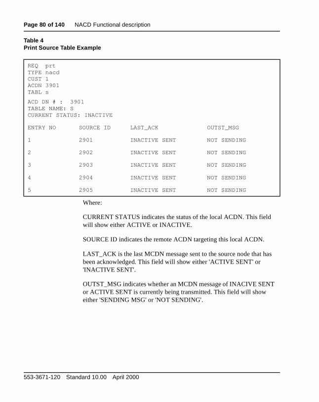
Page 80 of 140 NACD Functional description
s
Table 4Print Source Table Example
REQ prtTYPE nacdCUST 1ACDN 3901TABL s
ACD DN # : 3901 TABLE NAME: SCURRENT STATUS: INACTIVE
ENTRY NO SOURCE ID LAST_ACK OUTST_MSG
1 2901 INACTIVE SENT NOT SENDING
2 2902 INACTIVE SENT NOT SENDING
3 2903 INACTIVE SENT NOT SENDING
4 2904 INACTIVE SENT NOT SENDING
5 2905 INACTIVE SENT NOT SENDING
Where:
CURRENT STATUS indicates the status of the local ACDN. This field will show either ACTIVE or INACTIVE.
SOURCE ID indicates the remote ACDN targeting this local ACDN.
LAST_ACK is the last MCDN message sent to the source node that habeen acknowledged. This field will show either 'ACTIVE SENT' or 'INACTIVE SENT'.
OUTST_MSG indicates whether an MCDN message of INACIVE SENTor ACTIVE SENT is currently being transmitted. This field will show either 'SENDING MSG' or 'NOT SENDING'.
553-3671-120 Standard 10.00 April 2000

NACD Functional description Page 81 of 140
rget s at ic,
ithin inues
ame time.
l is m urs as the
The ll nt. If
in the
ts are uest,
l.
Cascade routingA Call Request from the Source ACD DN is the first message sent to a Tanode to queue the call waiting for the next available agent. The call staythe Source node receiving the treatments defined for that ACD DN (MusRAN, etc.).
Network ACD sends out Call Requests to search for an available agent wthe system. Only one Call Request is sent at a time, but the system contto search until an agent is found. That is, while the first Call Request is pending at a Target, the system can send another Call Request for the scall to another Target. Up to 20 Call Requests can be pending at any one
If the duration timer (DURT) for a particular Target expires before the calanswered, there may be only 19 Call Requests pending. Then, the systeresends the Call Requests to maintain the 20 pending. The Cascade occthe Call Requests are issued individually, and the system works throughRouting Table issuing Call Requests to Targets with successively longertimers as illustrated in Figure 2.
Targets are arranged automatically according to increasing timer values.longer a call waits, the farther down the routing table it goes. That is, CaRequests cascade through the listed Targets looking for an available agethe timers for each Target are the same value, then the Targets are listedorder they are entered into the database.
As soon as the call is answered, or abandoned, all pending Call Requescanceled. That is, the system must follow through the process—Call ReqFree Agent notification, Agent Reserve, and Call Presentation (or abandoned)—and then cancel all outstanding Call Requests for that cal
Network ACD Description and operation
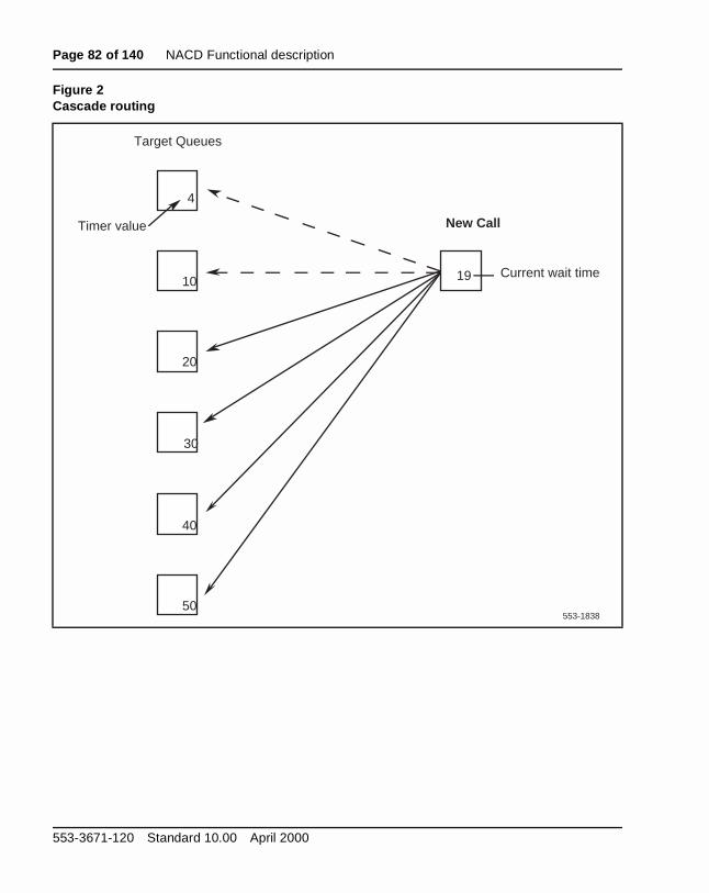
Page 82 of 140 NACD Functional description
Figure 2Cascade routing
553-1838
19
Target Queues
50
30
20
10
4
40
Timer value
Current wait time
New Call
553-3671-120 Standard 10.00 April 2000

NACD Functional description Page 83 of 140
as nd
ue CD the
e eue.
o a e at is
om
Dynamic status changeCertain events and conditions within the system allow the status for a particular queue to change automatically—a dynamic status change. Conditions that cause the status of a Target ACD DN to change are as follows:
• Night Service (NSVC):
When the Target ACD DN goes into Night Service, the status automatically changes to Closed at all its Source ACD DNs. As soonone agent or supervisor logs in, the ACD DN is taken out of NSVC, athe status is automatically changed to Active.
• Traffic volume:
When calls in the Call Request queue exceed the Call Request QueSize (CRQS) threshold, the status changes to Closed. The Target ADN remains Closed to further network call requests until the calls in queue fall by the Flow Control Threshold (FCTH) difference.
CRQS – FCTH = difference
Example:
Set these parameters in service change:
CRQS = 80
FCTH = 20
When the queue = 80, the Target is Closed (CRQS = 80)When the queue = 60, the Target is Active (CRQS – FCTH = 60)
• Manual Close:
CRQS = 0
CRQS can never be lower than the flow control threshold. Setting thCRQS to zero in service change or Load Management closes the quThe Call Request queue shuts down. When the CRQS is changed tpositive value again, the Target becomes active. The CRQS must bleast the FCTH + 1 or 20, whichever is greater. The maximum value255 with a default of 100.
You can also remove or close the queue by removing that ACD DN frthe Routing Table for that time frame (Day or Night).
Network ACD Description and operation
Page 84 of 140 NACD Functional description
D st
le, be the r the
rved h an nt to
n or rved
d
the r rget
Incoming callsIncoming calls to a Network ACD site are initially handled as any other ACapplication. That is, incoming calls are queued for presentation to the firavailable agent.
Call RequestsWhen calls have waited longer than the timer values in the Routing Tabcalls can be diverted to Target agents for call presentation. Targets can local or remote. Calls that are to be diverted to a remote Target remain inqueue of the Source ACD DN, and the software sends a Call Request oveISDN D-channel to queue Call Requests at the Target node.
When an agent becomes available at the Target node, that agent is resefor that particular call. The Target node responds to the Source node witAgent Free notification over the D-channel. Only after receiving the AgeFree notification is the voice call physically diverted from the Source nodethe Target node and presented to the reserved agent.
Reserve Agent Timer (RAGT)The Reserve Agent Timer keeps the agent reserved until call presentatiotimeout. The timer also prevents a situation where an agent may be reseindefinitely.
The Reserve Agent Timer is customer defined in service change LD 23 (2 – (4) – 30) and Load Management (RAGT). When an agent is reservewith Countdown Allowed (CNTA) CLS defined in LD 11, the RAGT countdown is shown on the agent’s Digit Display.
The agent being reserved has a Reserve Agent Timer with countdown display. The countdown display starts when the Reserve Agent Timer (RAGT) starts, and counts down by increments of 2 seconds, to zero. If call is not presented to the Target agent before the Reserve Agent Time(RAGT) expires, that call remains at the originating Source queue. The Taagent is returned to the idle agent queue.
553-3671-120 Standard 10.00 April 2000
NACD Functional description Page 85 of 140
d ns
t Free the imer the fer to
cancel the
e
l
When a call is presented or answered (depending on the display CLS allowed), the Digit Display shows the appropriate call information—dialeDN, DNIS number, CLID, and so on. Diverting the call and system functioshow the agent’s display to the caller.
When a Target agent becomes available, the Target node sends an Agennotification message to the Source ACD DN. The agent is removed fromidle agent queue and reserved until the network call is presented. If the texpires before the call is presented, the agent is returned to the front of idle agent queue, and the call remains at the Source ACD DN queue. Re“Priority Agents (PRI)” on page 94.
Canceling Call RequestsThere are some situations that can change an agent’s reserved status or a Call Request, affecting the timer. Agent set key operations can changestatus of a station to unreserved. Cancellations for other reasons may binitiated by the Source or Target ACD DNs also.
Source nodeThe Source node cancels Call Requests on the following events:
• call is answered by any agent or supervisor
• call is abandoned
Cancellation messages are sent to all remote Target ACD DNs with CalRequests pending for that ACD call.
Target nodeA Target ACD DN cancels Call Requests on the following events:
• Duration Timer (DURT) expires
• Reserve Agent Timer (RAGT) expires
CAUTIONCall modification information may be lost.
If the call is transported over a node that does not support the same release or features, certain call information is lost and will not be displayed on the terminating telephone.
Network ACD Description and operation

Page 86 of 140 NACD Functional description
g
r that ned
res ue
hest
ith rity
s at If y are
in
• Key Operation: An agent activates keys or logs out before the Call Set-up message is received (as in using the NRD/MSB keys)
• Night Service: If a Target ACD DN goes into Night Service, all pendincalls in its Call Request queue are cancelled
Queue priorities Each agent answers incoming calls based on the priorities established foACD DN. There are three different queue configurations that can be defifor Network ACD.
Oldest Call in Network (OCN)This option takes the oldest call in the network overall. This option requithe Oldest Call in Network (OCN) be enabled, and the High-Priority Que(HPQ) be disabled in LD 23:
OCN = YES
HPQ = NO
The system compares calls from queues for that target ACD DN. The higpriority call that has waited the longest is the call presented to the next available agent.
Own TOF Queue FirstThis option selects the oldest call from the ACD DN’s own TOF queue. Wthis preference, both the Oldest Call in Network option and the High-PrioQueue option should be disabled in LD 23:
OCN = NO
HPQ = NO
If there are no calls in the Source Timed Overflow queue, the system lookcalls in the Call Request queue and Source Timed Local Flow-in queue.there are no calls in either of those queues, then calls in the High-Prioritqueue and nonpriority queues are routed next. Calls for a Target ACD DNbest answered by the agents for that ACD DN. With this configuration, calls are selected in the following order:
1 the oldest call in the agent’s own TOF
2 the oldest High-Priority call in the Call Request queue or Local Flow-queue
553-3671-120 Standard 10.00 April 2000
NACD Functional description Page 87 of 140
rity est
d
to d in call.
or the ing
Free
the
s
3 High-Priority calls
4 nonpriority calls
Own TOF and High-Priority Queue over the networkThis option presents calls from the agent’s own TOF queue and High-Prioqueues before presenting calls from Source TOF queues and Call Reququeues.
With this preference, the Oldest Call in Network option should be disableand the High-Priority Queue option should be enabled in LD 23:
OCN = NO
HPQ = YES
With this configuration, calls are selected in the following priority:
1 the oldest call in the agent’s own TOF queue
2 the oldest call in the agent’s High-Priority queue
3 the oldest call from the Call Request queue or Local Flow-in queue
4 the oldest call in the agent’s nonpriority queue
Call presentationThe customer must first define call processing priorities for the system, asdescribed in the previous section. Then, the system follows this procedurepresent a call to the next available agent. Calls diverted by NACD are placethe queue for the Source ACD DN, until an agent becomes available for the
When an agent becomes available, that agent is reserved by the system fNACD call. The Reserve Agent Timer starts, to prevent the agent from bereserved indefinitely. During the countdown, the system sends an Agent notification over the D-channel to the Source ACD DN.
Receiving the Agent Free notification, the Source ACD DN then diverts physical voice call to the Target agent reserved for that call. On call presentation the display shows the appropriate information—dialed DN,DNIS number, CLID, for example. Diverting the call and system functionare completely transparent to the caller.
Network ACD Description and operation
Page 88 of 140 NACD Functional description
call
tions
sult
e
D
1.
e
If the Reserve Agent Timer expires before the call can be presented, theremains at the Source ACD DN.
Feature interactionsFeatures and services listed here are described in detail in other publicaas ACD features or as software features compatible with Generic X11 software. Refer to the list of supporting documents in the front of this document. If a needed reference cannot be found in that list, please conwith your Nortel Networks representative.
Only calls eligible for TOF treatment are eligible for NACD treatment. Thfollowing calls are not eligible:
• ACD Ring Again If RGA is applied to a call, it is not eligible for NACD.
• Call Park Recall Parked calls that time out and recall back to the ACagent are not eligible for NACD.
• Non-ACD Interact Digit translation is not supported on Target IDs within any Routing Table.
• Teleset Messaging Calls actively in Teleset Messaging are not supported by NACD.
Network ACD interacts with ACD and basic X11 features of the MeridianThese interactions are described in the following section.
ACD interactionsAgent (AGT) LampsAn AGT lamp shows the ACD supervisor the status for every agent in thgroup. The lamp states, explained in Automatic Call Distribution: Feature Description (553-2671-110), are updated every time an agent’s status changes.
When an agent is reserved for network calls, the AGT key/lamp on the supervisor’s station is in the slow flash state.
553-3671-120 Standard 10.00 April 2000
NACD Functional description Page 89 of 140
e d
ls in the
ble t of
ues:
r
r
ACD Calls Waiting (AWC)The ACD Calls Waiting key uses lamp states to show the agent when thnumber of calls waiting in the queue has exceeded the customer-definethreshold values. The lamp states work in conjunction with the normal Overflow by Number and Interflow features. However, by an optional command in LD 23, the AWC lamp states are enhanced in the NACD environment.
With the new lamp state option (NCWL) enabled, the Busy Threshold (BYTH) and Overflow Threshold (OVTH) apply only to Overflow by Number and Interflow conditions, but do not change the lamp states. Calthe Call Request and Local Flow-in queues are included when adding upcalls in queue for lamp state updates.
The new lamp state settings separated from BYTH and OVTH are availato all ACD Package B users with X11 Release 24 and later. IndependenNACD, thresholds that now update lamps are defined by the customer inservice change LD 23 and Load Management.
These lamp states are based on the sum of all calls in the following que
• the agent’s TOF queue
• the agent’s High-Priority queue
• the agent’s nonpriority queue
• the Local Flow-in queue
• the Call Request queue
The Calls Waiting lamp states are as follows:
Dark The sum of all calls in these queues is less than the Call Waiting Threshold (CWTH).
Steadily Lit The sum of all calls in these queues is equal to or greaterthan the CWTH, but less than the Call Waiting Lamp Flash(CWLF) threshold.
Slow Flash The sum of all calls in these queues is equal to or greatethan the CWLF threshold, but less than the Call Waiting Lamp Fast Flash (CWLW) threshold.
Fast Flash The sum of all calls in these queues is equal to or greatethan the CWLW threshold.
Network ACD Description and operation
Page 90 of 140 NACD Functional description
D on.
e e
r on
Dialed Number Identification Service (DNIS)The DNIS information is propagated to remote Target nodes. On call presentation, it is displayed on the Digit Display.
If the call is incoming on a non-ISDN trunk, the displayed information includes only the trunk access code, to show that it is an ACD call.
Display Queue (DWC) keyThe lamp states for the Display Queue (DWC) key are updated for NACenhancements, as explained above in the Calls Waiting (AWC) descriptiThe DWC display shows queue status in the following format:
a a a – b b b – c c c – d d d d
where:
a a a = sum of calls waiting in queue: Source TOF, High-Priority, nonpriority
b b b = agent positions available
c c c = waiting time for the oldest call in these queues: Source TOF, High-Priority, nonpriority
d d d d = sum of all calls in the following queues: nodal CCR, Flow-in, and Call Request queues
The supervisor can monitor the nodal Flow-in queue separately using thDisplay (DSP) key. Push the DSP key and dial the Source ACD DN. Thdisplay then shows the sum of calls in the Source TOF queue and Call Request queue.
Headset or MSB Logout (HOML)The HOML option allows an agent to log out by removing the headset ogoing on hook without using the Make Set Busy (MSB) key. Logout while Agent Reserve causes a cancellation message.
553-3671-120 Standard 10.00 April 2000

NACD Functional description Page 91 of 140
with gent. f the
an
n
e
Individual DN (IDN) keyThe IDN key can be any one of the following key types:
When an agent or supervisor activates any IDN key while reserved, a cancellation message is sent to the Source node.
If any IDN key is used by a remote Target agent when being presented a call from the Call Request queue, the call is terminated to another idle aIf there are no idle Target agents available, the call remains at the front oTarget TOF queue and will be the first one to be answered.
Call Interflow (IFDN)Call Interflow takes precedence over Network ACD routing. That is, callsdiverted to the IFDN are not routed by NACD. Network calls diverted to IFDN lose all the network information, so that information cannot be displayed on the terminating telephone.
If the Target ACD DN is a local ACD DN, Interflow and recall to Source cabe used. If the Target ACD DN is a remote ACD DN or a non-ACD DN, Interflow is not supported.
Disabling Interflow is recommended. Set the timer value to zero (0) in throuting table for those ACD DNs that need calls immediately diverted.
DIG Dial Intercom Group
HOT Hot Line
MCN Multiple Call, Nonringing
MCR Multiple Call, Ringing
PLN Private Line, Nonringing
PLR Private Line, Ringing
SCN Single Call, Nonringing
SCR Single Call, Ringing
VCC Voice Call
Network ACD Description and operation
Page 92 of 140 NACD Functional description
with a ent.
f the
D
Key featuresWhen an agent is reserved, activation of the following keys removes theposition from reserved status:
If these keys are used by a remote Target agent when being presented call from the Call Request queue, the call is terminated to another idle agIf there are no idle Target agents available, the call remains in the front oTarget TOF queue.
Night Call Forward (NCFW)Night Call Forward is used only if there is no Night Table defined for an ACDN.
AAG Answer Agent key
ACNT Activity Code key
AMG Answer Emergency key
ASP Answer Supervisor key
ADL Auto Dial key
CFN Call Forward key
MSB Make Set Busy key
NRD Not Ready key
OBV Observe Agent key
RAG Ring Agent key
SCC and SSC Speed Call key
553-3671-120 Standard 10.00 April 2000
NACD Functional description Page 93 of 140
d:
d
f the
the ars
ew al
ing less
Night Service (NSVC)With NACD, there are three Night Service treatments that can be define
• Night RAN Route with Night Tables
Callers receive Night RAN, while the call is monitored for the timers defined for Targets nodes.
• Night Tables only
No Night RAN is given, while the call is monitored for the timers definefor Targets.
• Night Tables with Delay Night RAN Treatment (DNRT)
With active entries in Night Tables (DNRT) on, callers will get Day treatment. The FRT must be 4 seconds greater than the timer value olast entry in the Night Table for this to work. When all entries in the Night Table are inactive, then a Night RAN is returned to inform the caller that the network is closed.
Note: When a caller accesses the queue in Night Service and uses NACD Night Table (the Night Table has open Targets), the caller hefirst and second RAN.
Transition mode: When the Source ACD DN goes into Night Service via the NSVC key (dialing T [8]), calls already in queue still access the Day Table, but all ncalls access the Night Table. If there is no Night Table defined, traditionNight Treatment is given.
Night mode:The Source ACD DN goes into the Night mode using the NSVC key (dialN [6]), when all agents log out. Then all calls access the Night Table, unthey have outstanding Call Requests from the Day Table.
• Source node in Night Service
— Transition mode:
– new calls access the Night Table
– existing calls access the Day Table
— Night mode:
Network ACD Description and operation
Page 94 of 140 NACD Functional description
l Day
D. to
tial
ent ith
– new calls access the Night Table
– existing calls that have pending Call Requests from the DayTable are honored, but there is no more searching of the DayTable
• Target goes into Night Service
— Transition and Night mode:
– new Call Requests are denied
– existing Call Requests are canceled
When the Source ACD DN comes out of Night Service, only current CalRequests accessing the Night Table still apply. All new calls access the Table. Only calls without outstanding Call Requests can access the DayTable.
Overflow by Number (OVDN)Overflow DNs defined at the OVDN prompt in LD 23 are not used by NACThey are used by Overflow by Number only. The same ACD DNs can bedefined in the NACD Routing Tables as local Targets. OVDN then recallsSource when the call waits longer than the timer.
Priority Agents (PRI)PRI allows certain agents or groups to have priorities defined for preferencall presentation. Agents or groups with higher priorities are linked morereadily to the front of the idle agents queue. Lower priority agents are presented with calls only when all higher priority agents are busy.
If a priority agent is reserved but is not presented with a call, the priority agwill be put after those agents with higher priority and in front of agents wequal priority.
553-3671-120 Standard 10.00 April 2000
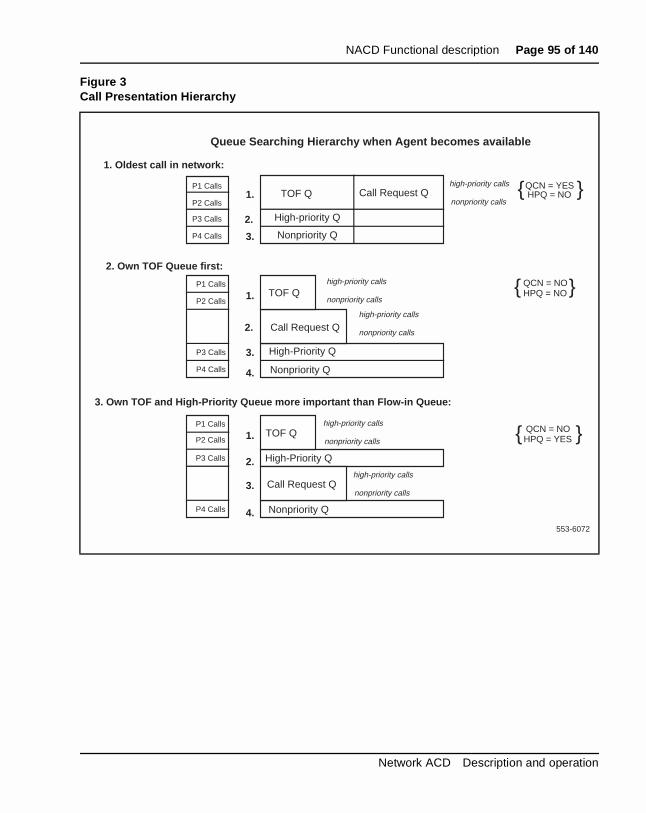
NACD Functional description Page 95 of 140
Figure 3Call Presentation Hierarchy
Queue Searching Hierarchy when Agent becomes available
TOF Q
High-priority Q
Nonpriority Q
Call Request Qhigh-priority calls
nonpriority calls
QCN = YESHPQ = NO1.
2.
3.
1. Oldest call in network:
2. Own TOF Queue first:
3. Own TOF and High-Priority Queue more important than Flow-in Queue:
{ }
TOF Q
High-Priority Q
Nonpriority Q
Call Request Q
high-priority calls
nonpriority calls
QCN = NOHPQ = NO1.
2.
3.
{ }
4.
high-priority calls
nonpriority calls
TOF Q
High-Priority Q
Nonpriority Q
Call Request Q
high-priority calls
nonpriority calls1.
2.
3.
4.
high-priority calls
nonpriority calls
QCN = NOHPQ = YES{ }
P1 Calls
P2 Calls
P3 Calls
P4 Calls
P1 Calls
P2 Calls
P3 Calls
P4 Calls
P1 Calls
P2 Calls
P3 Calls
P4 Calls
553-6072
Network ACD Description and operation

Page 96 of 140 NACD Functional description
at
the
ents. k
nly
ted ute.
lay eue, call
Secondary DN call blocking (SDNB)Secondary DN call blocking prohibits call presentation to an agent’s secondary DN while that agent is active on an ACD call.
Secondary DN calls are blocked when an agent is reserved.
If the agent is no longer reserved, and IDN is MADN SCR, the light for thDN flashes.
Time Overflow (TOF)If Routing Tables are not defined, then TOF operates as usual. Refer topublications listed in “Supporting documents” on page 71 for a completedescription of TOF.
Feature interactionsCalling Line Identification (CLID)CLID numbers are sent across the link on call presentation to Target agWith CLID enabled, the originator’s name is sent across the network anddisplayed on the Target agent’s telephone only if each route has NetworCPND allowed. Refer to the ISDN Basic Rate Interface: Product Description (553-3901-100) and ISDN Basic Rate Interface: Administration (553-3901-300) for more details on Network CPND.
Call Party Name Display (CPND)CPND displays preprogrammed names associated with incoming calls oon M2317, M3000, and Meridian Modular telephones (M2216ACD-1 andM2216ACD-2). Names associated with this feature are only sent acrossnodes with the CPND package (95) equipped. More complete details onNetwork CPND are in the ISDN Basic Rate Interface: Product Description (553-3901-100) and ISDN Basic Rate Interface: Administration (553-3901-300).
Without CLID, a call from outside the network displays the name associawith the incoming route, if the Source node has a name defined for that ro
Call Forcing (FORC)After an ACD call is disconnected (by either party), there is a 2-second debefore the next call is accepted. If the next call is from the Call Request quthere is an additional delay from 0 to the Reserve Agent Time before theis presented to the agent.
553-3671-120 Standard 10.00 April 2000
Page 97 of 140
126
NACD EngineeringContent list
The following are the topics in this section:
• Reference list 99
• Dependencies 99
• Package dependencies 99
• Feature limitations 101
• Feature requirements 101
• ESN requirements 102
• Recommendations 104
• Customer configurations 104
• NACD engineering guidelines 105
• Target table definition 106
• Real-time impact 106
• Noncoincidence busy hour (time zone difference) 106
• ACD DN load at each node (spare capacity) 107
• Agent group size in an ACD DN 107
• Number of hops 107
• Parameter definition 108
• Flow Control (Overlay 23: FCTH) 108
• Call Request Queue Size (Overlay 23: CRQS) 108
Network ACD Description and operation
Page 98 of 140 NACD Engineering
• Resend Timer (Overlay 23: RSND) 109
• Reserve Agent Timer (Overlay 23: RAGT) 109
• Oldest Call in Network (Overlay 23: OCN) 109
• ACD agents requirement at each node 110
• Trunking requirements at the Source and Target nodes 110
• Duration Timer (Overlay 23: DURT) 111
• Network requirements 111
• Signaling link requirements between Source and Target nodes 111
• Overflow traffic estimation 112
• Average CCS loading per agent at each ACD DN 112
• Call register requirements 113
• Designing the NACD Routing Table 115
• ACD agent group size (P1) 116
• Average agent load at each target ACD DN (P2) 116
• Number of hops (P3) 117
• Noncoincidence busy hour and time zone difference (P4) 117
• Ranking of Target nodes on NACD Routing Table 118
• Timer value in NACD Routing Table 119
• Incremental impact engineering 122
• Trunking requirement 122
• Trunk traffic to source ACD DN 123
• Overflow traffic from source ACD DN 123
• Calls handled by the Source node agents 123
• Incremental traffic to each Target node 124
• Real-time requirement 124
• Call register requirement 125
553-3671-120 Standard 10.00 April 2000

NACD Engineering Page 99 of 140
ame
orks
nnel
rget
Reference listThe following are the references in this section:
• Capacity Engineering (553-3001-149)
• X11 Features and Services (553-3001-306)
• X11 Administration (553-3001-311)
DependenciesA Network ACD system requires that all nodes in the system have the sconfiguration. Networking parameters for ISDN and ESN must be consistent throughout all nodes or switches in the system with respect to NACD. Significant feature interactions may result unless all switches have the appropriate feature packages and classes of service enabled for NACD.
For the proper supporting generic and release, consult your Nortel Netwrepresentative.
MSDL Engineering GuidelinesWhen configurations include a tandem Meridian 1, ensure that the D-chalink speeds are engineered to meet required response and performanceobjectives. Please refer to the MSDL Engineering Guidelines in the Capacity Engineering (553-3001-149).
Package dependencies NACD requires X11 Release 25 or later issues of software. Expanded Tacapabilities are introduced with the Enhanced Overflow (EOVF) package(178), which is also a prerequisite for the Network ACD package (207).
Network ACD Description and operation
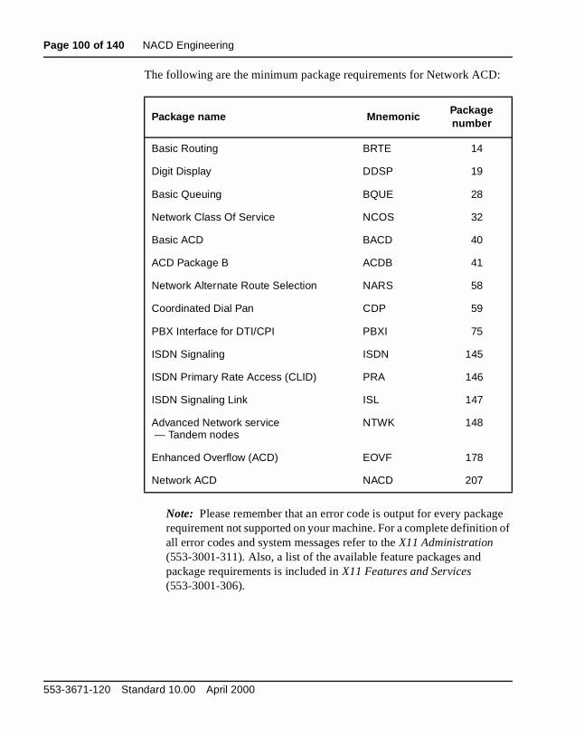
Page 100 of 140 NACD Engineering
:
ge n of
The following are the minimum package requirements for Network ACD
Note: Please remember that an error code is output for every packarequirement not supported on your machine. For a complete definitioall error codes and system messages refer to the X11 Administration (553-3001-311). Also, a list of the available feature packages and package requirements is included in X11 Features and Services (553-3001-306).
Package name MnemonicPackage number
Basic Routing BRTE 14
Digit Display DDSP 19
Basic Queuing BQUE 28
Network Class Of Service NCOS 32
Basic ACD BACD 40
ACD Package B ACDB 41
Network Alternate Route Selection NARS 58
Coordinated Dial Pan CDP 59
PBX Interface for DTI/CPI PBXI 75
ISDN Signaling ISDN 145
ISDN Primary Rate Access (CLID) PRA 146
ISDN Signaling Link ISL 147
Advanced Network service — Tandem nodes
NTWK 148
Enhanced Overflow (ACD) EOVF 178
Network ACD NACD 207
553-3671-120 Standard 10.00 April 2000

NACD Engineering Page 101 of 140
k.
CD
Q)
ata r
is
Feature limitationsCalls from trunks without Disconnect Supervision are not able to initiate Call Requests.
Automatic Trunk Maintenance (ATM) is not supported on ISDN PRA or ISL trunks.
Network CPND is only supported on Meridian 1 nodes within the networ
The NACD feature allows ACD agents at different locations (nodes) to service call over the network at remote targets. When an unanswered Acall is routed via NACD to a remote ACD DN node and the call is not answered by an ACD agent, the call is placed in a time overflow queue (TOof the remote ACD node, the call is not returned to the original ACD DNtarget node queue.
Tandem Tie Trunk Networks (TTTNs) are not supported by NACD.
Only one location per NACD node can be used with HLOC in LD 15.
Pretranslation is not supported on Target IDs in the Routing Tables.
Calls ineligible for NACD treatment are:
• ACD Ring Again calls
• Call Park Recall calls
• An active Teleset Messaging call
There should be one home location code per node.
There can be no more than 20 Call Requests pending for any one call.
Feature requirementsPrivate Network Identifier (PNI)A Private Network Identifier (PNI) relates to the customer number. It is required for interworking between switches. Within one network, use thesame PNI value in both the Customer Data Block (LD 15) and the Route DBlock (LD 16). When operating between different networks, the CustomeData Block PNI is the PNI for your switch and the Route Data Block PNIthe PNI for the remote switch where the route terminates.
Network ACD Description and operation
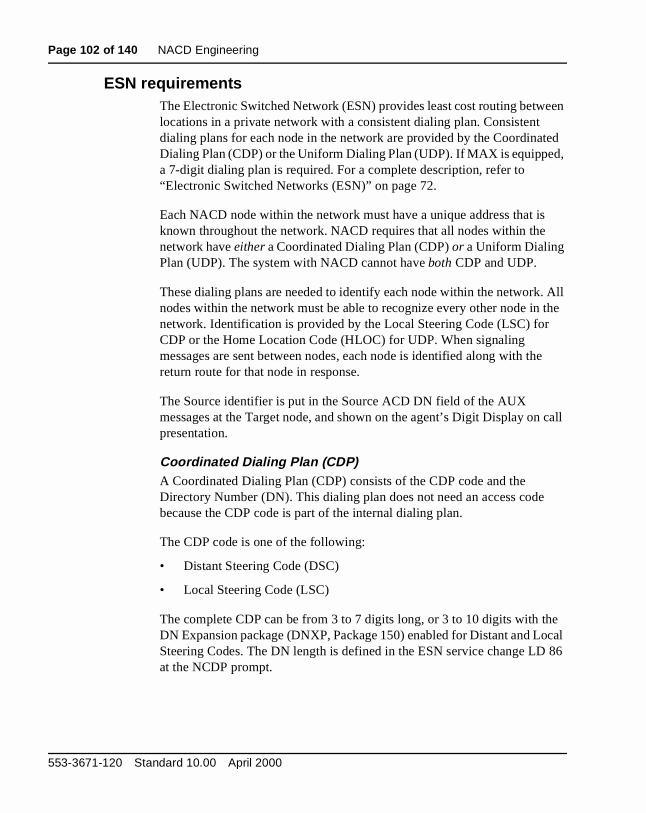
Page 102 of 140 NACD Engineering
een
ted ,
. All the
e
call
e ocal
86
ESN requirementsThe Electronic Switched Network (ESN) provides least cost routing betwlocations in a private network with a consistent dialing plan. Consistent dialing plans for each node in the network are provided by the CoordinaDialing Plan (CDP) or the Uniform Dialing Plan (UDP). If MAX is equippeda 7-digit dialing plan is required. For a complete description, refer to “Electronic Switched Networks (ESN)” on page 72.
Each NACD node within the network must have a unique address that isknown throughout the network. NACD requires that all nodes within the network have either a Coordinated Dialing Plan (CDP) or a Uniform Dialing Plan (UDP). The system with NACD cannot have both CDP and UDP.
These dialing plans are needed to identify each node within the networknodes within the network must be able to recognize every other node in network. Identification is provided by the Local Steering Code (LSC) for CDP or the Home Location Code (HLOC) for UDP. When signaling messages are sent between nodes, each node is identified along with threturn route for that node in response.
The Source identifier is put in the Source ACD DN field of the AUX messages at the Target node, and shown on the agent’s Digit Display onpresentation.
Coordinated Dialing Plan (CDP)A Coordinated Dialing Plan (CDP) consists of the CDP code and the Directory Number (DN). This dialing plan does not need an access codebecause the CDP code is part of the internal dialing plan.
The CDP code is one of the following:
• Distant Steering Code (DSC)
• Local Steering Code (LSC)
The complete CDP can be from 3 to 7 digits long, or 3 to 10 digits with thDN Expansion package (DNXP, Package 150) enabled for Distant and LSteering Codes. The DN length is defined in the ESN service change LDat the NCDP prompt.
553-3671-120 Standard 10.00 April 2000
NACD Engineering Page 103 of 140
g
C) ize runk ot
an
SC on the t all
ns:
in
f the are With use DP
The Target ACD DN identifier is the remote ACD DN defined in the RoutinTable, and can only use the Distant Steering Code (DSC).
Source ACD DN identifiers are composed of the Local Steering Code (LSfollowed by the Source ACD DN. Every node in the network must recognthe LSC used for Source identifiers as a Distant Steering Code (DSC). TSteering Codes (TSCs) are not supported by ISDN; and therefore, are nsupported by NACD.
Define 7-Digit CDPIf no CDP is defined or if the existing CDP is 7 digits long, then the CDP cbe used for the NACD application.
Overlay 86 ESN data block must have the number of digits in the CDP (NCDP) code prompt equal 7. Overlay 87 defines the 3-digit LSC. The Lmust have a DMI that deletes 3. A 3-digit DSC is required for each nodethe network. Overlay 15, Customer Data Block, must also define LSC asalready defined LSC from Overlay 87. This programming must be done athe nodes in the network.
Note: In Overlay 86, when defining Route List Entries that are associated with either DSCs or LOCs used with the NACD applicatio
— The routes (ROUT) must be only ISDN routes. Also, the ISDN routes cannot step to non-ISDN routes.
— The PNI defined for the routes must be equal to the PNI definedOverlay 15, Customer Data Block, of the node that it is directly connected to.
— No digit manipulation (DMI) can be defined; in other words, DMI = 0.
Uniform Dialing Plan (UDP)The Uniform Dialing Plan has an access code, a UDP code, and a DN. INetwork Alternate Route Selection (NARS, package 58) is enabled, theretwo access codes that can be used, AC1 or AC2, and the location code. the Basic Alternate Route Selection (BARS, package 57), you can only AC1. Access codes for either AC1 or AC2 can be 1 or 2 digits long. The Umust be 7 digits without the AC.
Network ACD Description and operation

Page 104 of 140 NACD Engineering
its all, call
2 de are
f
D,
y.
t the e,
enly
The UDP code can be any one of the following:
• Location Code (LOC)
• Home Location Code (HLOC)
If the Target node has a 5- to 7-digit ACD DN defined, only the last 4 digare used as an identifier. When the terminating telephone answers the conly the last 4 digits are shown as the CLID. The CLID can be used as aback number.
Source ACD DN identifications are built from the Home Location Code (HLOC) and the Source ACD DN. The HLOC must be included in the ACtranslation table. Every node on the network must define the location coused for Target DNs as part of the AC2 translation table. Target identifiersdefined in the routing tables.
RecommendationsCustomer configurations
Network ACD can function in three basic configurations: similar service,special service, and a hybrid of the two. There can exist a combination othese NACD configurations within the same network.
Similar Service NetworkThis configuration is used when there is only one service handled by NACand all ACD agents are equally capable of handling any incoming call.
Every ACD DN within the network must be defined in all the other ACD DN’s Routing Tables. Only the Oldest Call in Network (OCN) option is enabled, and all incoming trunks should be defined with the same priorit
OCN = YES
HPQ = NO
Special service networkHere, there may be different services being offered by agents throughounetwork. Each agent is specially trained for a particular product or servicbut is still able to answer any incoming call. The ACD user can define specialized services among groups of agents and still allow calls to be evdispersed among all available agents during peak traffic times.
553-3671-120 Standard 10.00 April 2000

NACD Engineering Page 105 of 140
r
ted.
lls eir
d
y e,
e
ith
Only the ACD DNs with similar functions should be defined as Targets foeach other. Every ACD DN should have OCN disabled (NO) and HPQ enabled (YES). All incoming trunks should be defined as High-Priority trunks.
OCN = NO
HPQ = YES
Hybrid networkA hybrid network is a union of the two configurations mentioned above. Different services or products are being offered, but they are closely relaA TOF call for one ACD DN should have precedence over other calls overflowing to the same ACD DN. Still, it is best to answer the oldest cafirst. After answering all TOF calls, agents return to answering calls in thown High-Priority queue.
Every ACD DN within the network must have all the other ACD DNs definein the Routing Tables. Then, both OCN and HPQ are disabled (OFF).
OCN = NO
HPQ = NO
NACD engineering guidelinesWhen independent Automatic Call Distribution (ACD) nodes are properlnetworked using the Network Automatic Call Distribution (NACD) packagthe overall performance of the network can improve in three areas:
• Reducing Average Speed of Answer (ASA)
• Increasing total ACD calls handled by the network
• Reducing ACD agents required to maintain the same service level
NACD is designed to allow the call distribution centers to function as onvirtual queue based on the length of time calls have waited for availableagents and on the work loads at each location.
Note 1: Do not forward calls to centers that are overloaded or understaffed. Use care when provisioning trunks between locations.Underprovisioning can result in agents being reserved for calls, but wno facility available for presenting the overflowed network call.
Network ACD Description and operation
Page 106 of 140 NACD Engineering
ot ront to
ing
e
PU y
ead by nt can ork. ring
Note 2: If a call is presented to a remote target ACD agent, and is nanswered by the remote target ACD agent, the call is returned to the fof the TOF queue of the remote target ACD DN. It is not routed backthe original ACD target node.
It is necessary to look at the call registers and the real-time effect of addNACD to new or existing Meridian switches.
The following are guidelines for establishing NACD, including:
• Target table definition
• Parameter definition
• Network requirements
• Design of the NACD Routing Table
• Incremental impact engineering
Target table definitionNACD automatically routes calls to available agents. For maximum efficiency, define the order of remote Targets in the NACD Routing Tablaccording to the guidelines below.
Real-time impactCPU real-time engineering is always required at the Source node. The Cof a tandem or remote Target node needs engineering only when its bushours coincide with those of the Source node.
Noncoincidence busy hour (time zone difference)Busy hours in branch offices are often similar for large organizations sprover a wide geographical area. NACD improves the utilization of facilitiesoverflowing calls arriving at the Source node to Target nodes in a differetime zone so that idle resources at Target nodes with different busy hoursbe fully utilized. This allows for a better balance of agents across the netwIt may also reduce the need to provide extra staff at the Source location dupeak times as the traffic is now distributed across the network.
553-3671-120 Standard 10.00 April 2000
NACD Engineering Page 107 of 140
one e N ed
re
ives
y
two DN
s a hest
ACD DN load at each node (spare capacity)The relative ACD DN load between the Source node and a Target node isof the most important considerations in determining where to overflow thwaiting call. If the average loading per ACD DN is known, then the ACD Dwith the lowest loading receives the highest priority for receiving networkoverflow calls.
To calculate the ACD DN with the lowest loading (or the highest spare capacity), use the following formula:
S = (33–A) × N
where:
S = spare capacity
A = agents load in CCS (Calls Accepted × Avg. Work Sec.) / 100
N = number of agents in the queue
Once the network is installed, it may be necessary to recalculate the spacapacity to provide better balance on the network.
The spare capacity is calculated only for the Target location since it recethe extra traffic.
If S is negative, the Target ACD DN is overloaded and cannot accept anoverflow traffic.
Agent group size in an ACD DNDue to the higher traffic carrying capacity of a larger service group, when ACD DNs have the same average agent loading per ACD DN, the ACD with the most agents receives a higher priority in the routing table.
Number of hopsIn general, a call with a number of switches involved in the call set-up requires more resources than a network call involving only two switches. Ageneral rule, the ACD DNs co-located in the Source node receive the higpriority in the routing table.
Network ACD Description and operation

Page 108 of 140 NACD Engineering
t eive
e 38
ster e
est
ns.
. call n
ws calls ing in
,
0% er er hen
The next consideration is for locations with only one hop or point-to-poinconnections. If possible, nodes requiring tandem connections should reca lower priority depending on how many tandem points are involved.
Note: The real-time impact of each NACD call is 56 ms at the Sourclocation, while tandem calls require 215 ms of real time. Each NACDcall requires 194 ms to set up, while a nonnetwork ACD call requires 1ms. Each time a Call Request is sent over the network, one call regiis required at the Source node and one call register is required at thTarget nodes. These call registers are required in addition to those necessary to establish the call. They are required only with Call Requmessaging for NACD calls.
Parameter definitionThe parameters used to control NACD are defined in the following sectio
Flow Control (Overlay 23: FCTH)The Flow Control option opens and closes the ACD DN for network callsOnce the number of Call Requests received over the network meets therequest queue size CRQS defined in Overlay 23, the queue is shut dow(INACTIVE) for network calls. The pending queue request size must be decreased by a value at least equal to the flow calls control threshold.
For example, a call request queue size of 50 with a flow control of 10 allothe queue to become inactive after 50 call requests are pending. After 10or 10 Call Requests have been answered or removed, leaving 40 remainqueue, the queue will reopen.
Call Request Queue Size (Overlay 23: CRQS)The Call Request Queue Size option (CRQS) determines the maximumnumber of Call Requests accepted by a Target Queue over the networkbefore the queue is declared closed for network calls.
It is recommended that the Call Request Queue Size be approximately 2higher than the number of trunks available for networking. If the customselects the Oldest Call in Network option (OCN), set this value at 5% ovtrunking capacity. This avoids reserving agents for calls on the network wtrunking facilities are unavailable. Flow Control (FCTH) is typically set at25% of the call request queue size.
553-3671-120 Standard 10.00 April 2000
NACD Engineering Page 109 of 140
rget pires, ithout send ork
en fic ls to
odes.
nt is et at
for fore d nly
d of s are
The CRQS must be defined for each ACD DN in the network.
Resend Timer (Overlay 23: RSND)This is the length of time the Source node waits for a response from the Tanode after sending a Call Request message. When the Resend Timer exanother message is sent. If the second Call Request message expires wa response, the Call Request is removed from the network queue. The ReTimer is set to a 4-second default and should be changed only if the netwuses multiple hops and ISL with lower baud rates.
A single hop typically requires 100 ms of real time to set up the call. Whthe Resend Timer is too large, the control function of the timer to limit trafto busy nodes is lost. If the Resend Timer is too small, the access of calnodes may be limited unnecessarily.
The Resend Timer must be defined for the Source node and the Target n
Reserve Agent Timer (Overlay 23: RAGT)The Reserve Agent Timer indicates the maximum amount of time an agereserved for a network call. The range is 2–30 seconds with the default s16 seconds. The Reserve Agent Timer can be changed using 2-secondincrements.
If the Reserve Agent Timer is set too high, the agent is reserved waitingcalls. If the Reserve Agent Timer is set too low, the agent may be freed bethe network facility can set up the call. Different timer settings can be triethrough Load Management. Subsequent calls are presented to agents oafter the Reserve Agent Timer has expired.
The RAGT must be defined only for Target queues.
Oldest Call in Network (Overlay 23: OCN)This feature determines if the oldest call in the network is answered aheacalls to the Source location. Use caution with this feature. Because agentreserved for network calls, agents may remain idle while calls wait in thelocal queue.
Network ACD Description and operation
Page 110 of 140 NACD Engineering
to equal ws
to res lly, to
ity is
ither king
gent ls not
er n
dy
g
To avoid reserving all the agents for network calls, split the ACD group intwo areas: one area for all calls and the second area for a group of agentsto the number of tie lines between the network locations. This solution allolocal calls to overflow by time into the area for all calls.
The OCN option must be defined only for Target queues.
ACD agents requirement at each nodeThe current method of calculating ACD agents inflates ACD calls by 30%allow for peak traffic during busy hours. The provisioning of agents requi30% spare capacity to cover traffic peaks. When NACD is applied normathis 30% spare capacity is not necessary since queued calls are offeredother nodes in the network after the designation overflow timer expires. However, if all nodes peak at the same busy hour, the 30% spare capacstill required.
Trunking requirements at the Source and Target nodesEach node on the network must have a connection to the Source node, edirectly or through one or more tandem nodes. It is assumed that the trunrequirements have been satisfied to handle existing traffic. For NACD, estimate the incremental requirement for carrying overflow calls to eachTarget node.
In the current engineering procedure, there is an adjustment similar to atraffic on the trunking requirement for traffic peaking of 30%. Waiting calare eventually handled by other nodes with less average waiting and dooccupy the trunks.
Keep the peak load adjustment, but reduce the Average Speed of Answ(ASA) by half in the trunk calculation to allow for the potential reduction iwaiting time. Modify trunk traffic calculations to the Source node by multiplying Average Busy Season Busy Hour (ABSBH) traffic by 1.3 to account for trunk traffic peak load. If the level of given traffic in calls alreareflects the peaking factor, then replace 1.3 with 1.0 in the following calculation.
Trunk Traffic = (Offered Calls × 1.3 × DCP/100) + (Offered Calls × 1.3 × 0.5 × ASA/100) CCS
Direct Call Processing (DCP) is the time in seconds that is spent handlinincoming ACD calls.
553-3671-120 Standard 10.00 April 2000
NACD Engineering Page 111 of 140
he me ulate
est all
he st ers
e
s so L, le
Where the objective of networking is to reduce the number of agents in tSource node while maintaining the same level of service, perform the sacalculation but reduce the number of agents at the Source node and calctrunk traffic without the 50% reduction of ASA in the above formula.
Duration Timer (Overlay 23: DURT)The Duration Timer indicates how long a Target node honors a call requfrom the Source node. If the timer expires, the call is removed from the crequest queue. The range of the Duration Timer is 15–45 minutes with tdefault set at 30 minutes. If this timer is too large, the network call requequeues may become overcrowded. If the timer is too small, waiting custommay be cut off from receiving services.
This timer must be defined only for Target queues.
Network requirementsThe requirements for establishing NACD on a network are outlined in thsections that follow.
Signaling link requirements between Source and Target nodes
If the signaling message for NACD applications is carried by a PRA D-channel between two nodes, the PRA D-channel’s signaling capacity ilarge that engineering of the link is not required. If the signaling link is ISthe data rate of the signaling link must be determined. Use care in multiphops to ensure recalculation of all the traffic on the ISL link. For multiplehops, engineer all links to the same baud rate. Avoid using ISL links at different speeds since this can block messages at the tandem location.
The formula to calculate the ISL/PRA rate is:
Number of NACD calls × .63 = BPS
or Numbering NACD calls = BPS/0.63
where BPS = bytes per second Baud rate
Network ACD Description and operation
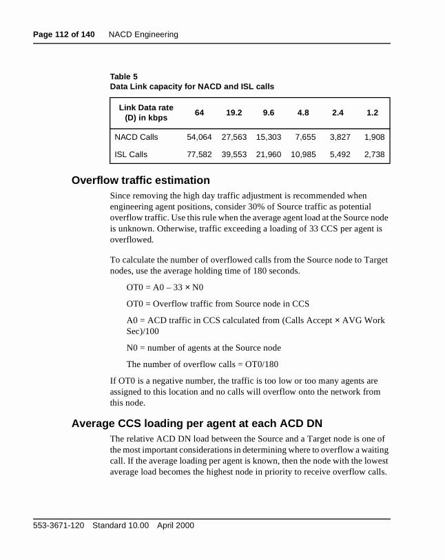
Page 112 of 140 NACD Engineering
ode is
rget
of ing est lls.
Overflow traffic estimationSince removing the high day traffic adjustment is recommended when engineering agent positions, consider 30% of Source traffic as potential overflow traffic. Use this rule when the average agent load at the Source nis unknown. Otherwise, traffic exceeding a loading of 33 CCS per agentoverflowed.
To calculate the number of overflowed calls from the Source node to Tanodes, use the average holding time of 180 seconds.
OT0 = A0 – 33 × N0
OT0 = Overflow traffic from Source node in CCS
A0 = ACD traffic in CCS calculated from (Calls Accept × AVG Work Sec)/100
N0 = number of agents at the Source node
The number of overflow calls = OT0/180
If OT0 is a negative number, the traffic is too low or too many agents areassigned to this location and no calls will overflow onto the network fromthis node.
Average CCS loading per agent at each ACD DNThe relative ACD DN load between the Source and a Target node is onethe most important considerations in determining where to overflow a waitcall. If the average loading per agent is known, then the node with the lowaverage load becomes the highest node in priority to receive overflow ca
Table 5Data Link capacity for NACD and ISL calls
Link Data rate (D) in kbps
64 19.2 9.6 4.8 2.4 1.2
NACD Calls 54,064 27,563 15,303 7,655 3,827 1,908
ISL Calls 77,582 39,553 21,960 10,985 5,492 2,738
553-3671-120 Standard 10.00 April 2000

NACD Engineering Page 113 of 140
t is e
are ting
s
node
)
red
e
Average Agent Loading in CCS can be calculated from the ACD DN performance report. The equation is as follows:
Avg. Agent Loading in CCS = Average Work/Manned % × 36/100
The value of Work/Manned % from a Target ACD DN performance reporthe average traffic level of the Target ACD DN during the busy hour of thSource ACD DN.
Call register requirementsThe incremental requirements for call registers between ACD and NACDthe additional call registers required at the Source node to hold calls waito be overflowed to Target nodes. The recommended procedure is:
X = Calls/hours overflowed to all Target ACD DNs
This is OT0 ×100 /HT
Y = Calls/hours overflowed to the local Target ACD DNs
This is (OT1+...+OTk) × 100/HT, where k is the number of Target ACD DNco-located in the Source node.
ASA = Average Speed of Answer in seconds required at the Source
HT = Average holding time of an NACD call (default is 180 seconds
Q = Average number of NACD timers expired before the call is answe
(Default is 1.5 queues)
W = Number of calls overflowed from other nodes to the Source nodduring the busy hour (should be 0 for an efficient network)
t = The first timer value in the NACD table
CRQ = Call Request Queue size
Incremental CR Traffic at Source nodeSnacd = (X+W) × ASA × Q/100 + (X–Y) × HT/100 ccs
Incremental CR Traffic at Target nodeTnacd = CRQ × (ASA–t)/100 ccs
Incremental CR traffic at a combined Source and Target nodeSnacd + Tnacd
Network ACD Description and operation
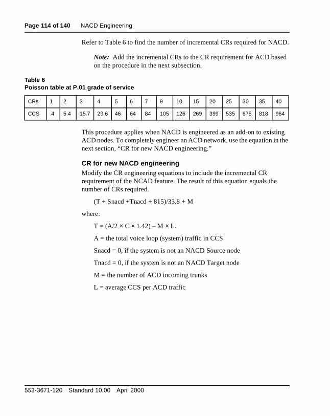
Page 114 of 140 NACD Engineering
D.
ed
ing the
Refer to Table 6 to find the number of incremental CRs required for NAC
Note: Add the incremental CRs to the CR requirement for ACD bason the procedure in the next subsection.
This procedure applies when NACD is engineered as an add-on to existACD nodes. To completely engineer an ACD network, use the equation innext section, “CR for new NACD engineering.”
CR for new NACD engineeringModify the CR engineering equations to include the incremental CR requirement of the NCAD feature. The result of this equation equals the number of CRs required.
(T + Snacd +Tnacd + 815)/33.8 + M
where:
T = (A/2 × C × 1.42) – M × L.
A = the total voice loop (system) traffic in CCS
Snacd = 0, if the system is not an NACD Source node
Tnacd = 0, if the system is not an NACD Target node
M = the number of ACD incoming trunks
L = average CCS per ACD traffic
Table 6Poisson table at P.01 grade of service
CRs 1 2 3 4 5 6 7 9 10 15 20 25 30 35 40
CCS .4 5.4 15.7 29.6 46 64 84 105 126 269 399 535 675 818 964
553-3671-120 Standard 10.00 April 2000
NACD Engineering Page 115 of 140
s, for
R
l
at he ndle the
qual ame.
C = the call register traffic factor
= 1 + 0.037 if CDR Charge Account is equipped
+ 0.074 if Authorization Code
+ 0.037 if Parallel CDR ports per customer
+ 0.150 if NARS/BARS/CDP
+ 0.150 if FCBQ and OHQ
+ 0.033 if ACD RAN
+ 0.019 if Teleset Messaging
+ 0.140 if Integrated Messaging System
+ 0.083 if Ring Again
+ 0.033 if Music Trunk
+ 0.067 if Call Park
+ 0.003 if New Flexible Code Restriction
+ 0.039 if ESN Signaling
The accuracy of the above CR equation proves accurate for larger groupexample, 100 CRs or more. It is not recommended for incremental estimations, which are usually smaller compared with the original ACD Ccalculation.
Designing the NACD Routing TableThe objective of designing an overflow Routing Table is to minimize the waiting time of calls in the network without creating excessive internodatraffic.
A point system is used to rank the potential of success if the waiting callthe Source node is put into the Call Request Queue of a Target node. TTarget ACD DN with the highest points indicates the best candidate to hathe overflow calls. The point system provides an objective way to evaluatespare capacity of a potential Target node.
Whenever the same numbers are assigned to multiple ACD DNs due to evalue, the next number will continue, but the total in the set remains the s
Network ACD Description and operation
Page 116 of 140 NACD Engineering
CD o on. P1, ups. s e. No
ent sed
r
ACD agent group size (P1)All Target ACD DNs are ranked according to the agent group size. The ADN with the largest agent group is assigned P1 = 5, the next one 4, and sIf there are more than five Target ACD DNs, the rest are assigned zero which means that no more preference is given to agent size after five groThis variable should not be greater than five in weight. If any two ACD DNhave the same number of agents, they should be assigned the same valumore than five ACD DNs will be assigned points in this category. In summary:
P1 = 5 for the ACD DN with the largest agent group
P1 = 4 for the next size group
P1 = 3 for the next
P1 = 2 for the next
P1 = 1 for the next
P1 = 0 for the 6th largest or less
Average agent load at each target ACD DN (P2)Assign the highest priority to the Target node with the lowest average agload during the Source node busy hour. If any two nodes have the sameaverage DN loading, assign the same points to each of them. The propopoint assignment is as follows:
P2 = 5 for the Target node with the lowest average agent loading peACD DN
P2 = 4 for the next lowest agent loading per ACD DN
P2 = 3 for the third lowest agent loading per ACD DN
P2 = 2 for the fourth lowest agent loading per ACD DN
P2 = 1 for the fifth lowest agent loading per ACD DN
P2 = 0 for agent loading higher than above
553-3671-120 Standard 10.00 April 2000
NACD Engineering Page 117 of 140
e the may ll. set
ove.
ng e
he call
m our.
r is in ree
nts,
Number of hops (P3)Multihop routes may require longer message delay, more CPUs to handlsame call, and more tandem trunks, may experience higher blocking, andcost more because of the charges associated with the distance of the caMultiple hops require a longer Reserve Agent Timer to wait for the call to up. Therefore, multihop routes are not encouraged.
The weight of this variable is more than for the other categories listed ab
P3 = 5 if Target is co-located with Source node
P3 = 0 if Target ACD DN is the next node
P3 = –5 if one hop in the route (one tandem connection)
P3 = –7 if two hops in the route
P3 = –9 if three hops in the route
If sufficient trunking is available in an existing tandem route so that blockiand cost penalties are of little concern, the user may change the negativweighting factor assigned to this parameter. One example may be:
P3 = –1 for one hop; P3 = –2 for two hops; P3 = –3 for three hops.
No limitation exists (except for a satellite, which allows only one hop) on tnumber of hops permitted in an NACD. In a private network, any tandem requiring more than three hops is unusual.
Noncoincidence busy hour and time zone difference (P4)P4 is the point allocated to the Target node with a different busy hour frothe Source node. Assign four points for each hour’s difference in busy hFor example, if the Source node experiences a busy hour at 9 a.m., andthe Target node has a busy hour at 11 a.m., then assign P4 = 8 points (= 4 × [11–9]) to the Target node.
This allocation of points is based on the absolute difference of busy houbetween the Source and Target node. For example, if the Source node Toronto and the Target node is Vancouver, the time zone difference of thhours brings 8 a.m. in Vancouver and 11 a.m. in Toronto into the same real-time hour. Since only an absolute difference in hours is allocated poino points for nodes are allocated in the example involving Toronto and Vancouver.
Network ACD Description and operation

Page 118 of 140 NACD Engineering
nnot
rs
and
odes
for in the
five
their
If the busy hour of the Source node and a Target node are not known or cabe located (inconsistency), let P4 = 0. In summary:
P4 = The points allocated to the Target node with different busy houfrom the Source node. Each hour difference is assigned 4 points.
P4 = 4 × the number of absolute hours difference between the SourceTarget node busy hours
P4 = 0 if there is no consistent busy hour at the Source and Target n
Ranking of Target nodes on NACD Routing TableEvery Target node is assigned points according to its relationship to theSource node based on the above four categories. All points are summedeach node. The node with the highest point total receives the top prioritythe routing tables. Nodes are ranked from Q1 to Q20, from the highest tolowest point total. The Routing Table allows a maximum of 20 DNs.
Q = P1 + P2 + P3 + P4
Negative values are ranked behind nodes with zero points.
Q1 > Q2 > Q3 > … Q20
If Qi equals Q (i + 1), choose the node closer to the Source node.
When an NACD has more than five nodes, several nodes after the first have zero Qi values. This is expected since they are far down the NACDtable. The preference of one node over the other is negligible, because chances of being offered overflow calls are diminishing.
553-3671-120 Standard 10.00 April 2000

NACD Engineering Page 119 of 140
s all is mer flow
e
the ond hen
not
and
he
ed otal ds.
Timer value in NACD Routing TableThe timer value should allow calls to queue on as many virtual queues apossible, but not congest call request queues. The length of a wait for a cclosely associated with the Average Speed of Answer (ASA) that a custospecifies and which the system is configured to meet. Therefore, the overtimer (Ti) should be a function of ASA. If the customer does not have anobjective ASA, then use the default time interval of 10 seconds. Recommended settings are as follows:
T1 = 10 seconds or ASA/n, whichever is smaller. The value of n is thnumber of Target DNs.
T2 = 20 seconds or 2 × ASA/n, whichever is smaller.
T3 = 30 seconds or 3 × ASA/n, whichever is smaller.
T4 = 40 seconds or 4 × ASA/n, whichever is smaller.
.
.
T20 = 200 seconds or 20 × ASA/n, whichever is smaller.
Whenever the timer value calculation results in an odd number, round it tosmaller even number, since the timer interval in NACD operates in 2-secincrements. Also, timer values for several DNs can be the same so that wthe NACD table contains many entries, a large timer for lower entries maybe necessary.
Engineering example: A 5 ACD DN and 4-Node NACDThe network consists of five ACD DNs and four nodes across three timezones with different busy hours. ACD DN1 is co-located with the Sourcenode ACD DN0. ACD DN3 is a tandem node between the Source node ACD DN4.
Figure 4 shows a simplified block diagram of the NACD. All DNs denote tACD DN.
• 1200 calls Average Busy Season Busy Hour (ABSBH) traffic are offerto the Source node (ACD DN0). The average agent service time, a tof direct call processing and post call processing time, is 180 seconThe ASA is 60 seconds.
Network ACD Description and operation

Page 120 of 140 NACD Engineering
.
S ts y
• The number of agents (Ni) is shown under each ACD DN.
• ACD DN0, ACD DN1, and ACD DN2 are within the same time zone
• ACD DN3 is one hour ahead of ACD DN0.
• ACD DN4 is one hour ahead of ACD DN3 and two hours ahead of ACD DN0.
• CCS per agent was estimated at 33 CCS/agent for ACD DN0, 30 CCfor ACD DN1, 28 CCS for ACD DN2, 25 CCS for ACD DN3, and 25CCS for ACD DN4 at the busy hour of ACD DN0. The number of agenat ACD DN0 was engineered to handle ABSBH calls. When High DaBusy Hour (HDBH) traffic is offered to ACD DN0, approximately 30%of calls overflow.
Use the following formula to calculate CCS per agent from the ACDreport:
— CCS per agent = 36 CCS × Total Work/Total Manned Time
Figure 4A 5-ACD DN and 4-node NACD network
DN0 DN160 30
DN220
DN340
DN480
553-5541
553-3671-120 Standard 10.00 April 2000
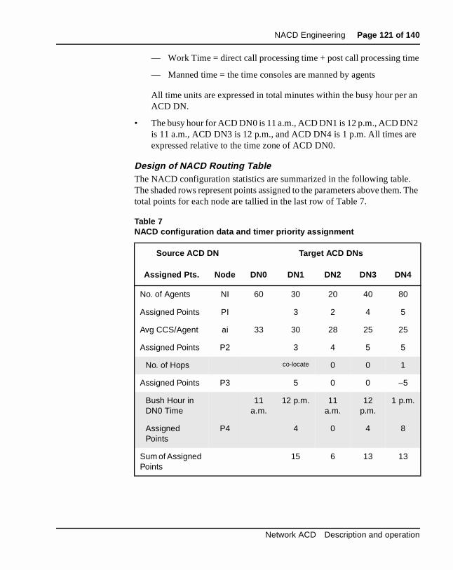
NACD Engineering Page 121 of 140
e
an
2 e
. . The
— Work Time = direct call processing time + post call processing tim
— Manned time = the time consoles are manned by agents
All time units are expressed in total minutes within the busy hour perACD DN.
• The busy hour for ACD DN0 is 11 a.m., ACD DN1 is 12 p.m., ACD DNis 11 a.m., ACD DN3 is 12 p.m., and ACD DN4 is 1 p.m. All times arexpressed relative to the time zone of ACD DN0.
Design of NACD Routing TableThe NACD configuration statistics are summarized in the following tableThe shaded rows represent points assigned to the parameters above themtotal points for each node are tallied in the last row of Table 7.
Table 7NACD configuration data and timer priority assignment
Source ACD DN Target ACD DNs
Assigned Pts. Node DN0 DN1 DN2 DN3 DN4
No. of Agents NI 60 30 20 40 80
Assigned Points PI 3 2 4 5
Avg CCS/Agent ai 33 30 28 25 25
Assigned Points P2 3 4 5 5
No. of Hops co-locate 0 0 1
Assigned Points P3 5 0 0 –5
Bush Hour in DN0 Time
11 a.m.
12 p.m. 11 a.m.
12 p.m.
1 p.m.
Assigned Points
P4 4 0 4 8
Sum of Assigned Points
15 6 13 13
Network ACD Description and operation
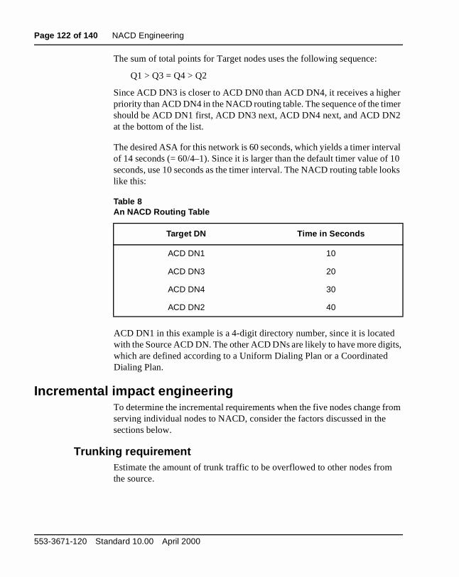
Page 122 of 140 NACD Engineering
er er
val f 10 oks
d its,
from
The sum of total points for Target nodes uses the following sequence:
Q1 > Q3 = Q4 > Q2
Since ACD DN3 is closer to ACD DN0 than ACD DN4, it receives a highpriority than ACD DN4 in the NACD routing table. The sequence of the timshould be ACD DN1 first, ACD DN3 next, ACD DN4 next, and ACD DN2at the bottom of the list.
The desired ASA for this network is 60 seconds, which yields a timer interof 14 seconds (= 60/4–1). Since it is larger than the default timer value oseconds, use 10 seconds as the timer interval. The NACD routing table lolike this:
ACD DN1 in this example is a 4-digit directory number, since it is locatewith the Source ACD DN. The other ACD DNs are likely to have more digwhich are defined according to a Uniform Dialing Plan or a Coordinated Dialing Plan.
Incremental impact engineeringTo determine the incremental requirements when the five nodes change serving individual nodes to NACD, consider the factors discussed in thesections below.
Trunking requirementEstimate the amount of trunk traffic to be overflowed to other nodes fromthe source.
Table 8An NACD Routing Table
Target DN Time in Seconds
ACD DN1 10
ACD DN3 20
ACD DN4 30
ACD DN2 40
553-3671-120 Standard 10.00 April 2000

NACD Engineering Page 123 of 140
ason y
n
k
for 8
rmal
um ls by
onds.
Trunk traffic to source ACD DNTrunk CCS = (1200 × 1.3 × 180/100) + (1.3 × [0.5 × 60] / 100) = 2808 + 468 = 3276
Where the 1200 offered calls to the Source node is the Average Busy SeBusy Hour (ABSBH) traffic, an additional 30% of traffic reflecting High DaBusy Hour (HDBH) peak level is added as recommended in Capacity Engineering (553-3001-149). If the customer defines the input traffic as aHDBH value, then the 30% adjustment is not required.
The ASA is reduced by half to reflect the effect on queuing time and trunloading. This incoming traffic (3276 CCS) requires 115 trunks to carry it (based on Poisson P.01).
The incoming trunk requirement is estimated from 3276 CCS. However,calculating actual overflow traffic, the portion associated with waiting (46CCS) should be discounted, since it is an overhead in addition to the nocall service time (180 seconds per call), which should not be used for estimating overflow calls.
Overflow traffic from source ACD DNOT0 = 2808 – (33 × 60) = 828 CCS or 460 calls (with 180 seconds HT)
Where 2808 CCS is the offered traffic to the ACD DN0 agents, the maximloading per agent is set at 33 CCS or 92%. The CCS is converted to calmultiplying 100/180 (= 828 × 100/180 = 460).
Calls handled by the Source node agents33 × 60 × 100/180 = 1100 calls handled by ACD DN0.
Agent loading is set at 33 CCS and the average holding time is 180 sec
Network ACD Description and operation

Page 124 of 140 NACD Engineering
her
her
) s to
ode e and
Incremental traffic to each Target node
1 The first ACD DN to accept overflow traffic: ACD DN1
The spare capacity at ACD DN1: S1, 1 = (33 – 30) × 30 = 90 CCS
OT1 = the smaller of OT0 (828 CCS) or S1,1 = 90 CCS or 50 calls
Since ACD DN1 is co-located with the Source ACD DN, no trunk is required to handle the overflow traffic.
2 The second DN to accept overflow traffic: DN3
The spare capacity at DN3: S3,2 = (33 – 25) × 80 = 640 CCS
OTC = the smaller of (828 – 90 – 320) or 640 = 418 CCS
At Poisson P.01 (a customer-designated value; blocking could be higfor a private network), the incremental trunks are 33. This traffic corresponds to 410 (= 178 + 232) overflowed calls.
3 The third DN to accept overflow traffic: DN4
The spare capacity at DN4: S4,3 = (33 – 25) × 80 = 640 CCS
OT3 = the smaller of (828 – 90 – 320) or 640 = 418 CCS
At Poisson P.01 (a customer-designated value; blocking could be higfor a private network), the incremental number of trunks required to handle 418 CCS is 21. The number of calls on this route is 232.
The traffic between the Source node and node 3 is 738 (= 320 + 418CCS. The required incremental trunks are 33. This traffic correspond410 (= 178 + 232) overflowed calls.
4 The fourth DN to accept overflow traffic: DN2
ACD – DN4: 232 × 0.63 = 147 bps. This is the data rate for the link between ACD DNs and ACD DN4.
Real-time requirementIncremental real time is the extra processing time required of the Source nCPU to handle NACD overflow calls to all Target nodes. The Target nodCPU does not require special engineering, since it is not in its busy hourhandles calls only when it has spare capacity.
553-3671-120 Standard 10.00 April 2000
NACD Engineering Page 125 of 140
er
BC
ed
est of odes
s one
0
ed.
me or to
H
Calls to all target ACD DNsIncremental real time of NACD overflow calls: 460 × 1.38 = 635 EBC.
where:
460 is the total number of overflow calls from the Source ACD DN.
Incremental real time of NACD/ACD calls handled at the Source node ovthe basic incoming trunk to SL-1 set calls = 1100 × 0.60 EBC, where 1100 is the total number of calls handled by the Source ACD DN agents. This Eshould be taken care of if the NACD configuration is evolved from an existing ACD node. If the Source ACD DN is a new NACD node convertfrom a non-ACD switch, then the real-time impact is 1295 EBC (= 635 + 660).
When a Target node becomes a Source node during its busy hour, the rthe nodes in the network are treated as Target nodes. When two or more nare Source nodes in the same busy hour, design the NACD routes tableat a time and treat the rest of the nodes as Target nodes.
Call register requirementFrom the “Overflow traffic from source ACD DN” on page 123 and “Incremental traffic to each Target node” on page 124, calls from ACD DNand to ACD DN1 can be calculated:
X = 460 calls (total overflow calls from ACD DN0)
Y = 50 calls (calls overflowed to ACD DN1)
Incremental Source node CR traffic: Snacd = (460 × 30 × 1.5/100) + (460 – 50) × (180/100) = 945 CCS, where an ASA of 30 seconds is assumReferring to a Poisson table with P.01 Grade of Service, the additional number of CRs required for the NACD application is 40.
Since none of the Target ACD DNs accepting overflow traffic has the sabusy hour as the Source node, assume that all Tnacd traffic (CR traffic feach Target ACD DN) can be absorbed by the spare CRs available duenon-busy-hour traffic overflowing to that Target ACD DN.
Note: Although the number of calls offered to the NACD is 1200, thenetwork is engineered for 1560 calls due to the ABSBH versus HDBconsiderations.
Network ACD Description and operation

Page 126 of 140 NACD Engineering
553-3671-120 Standard 10.00 April 2000

Page 127 of 140
128
e
ImplementationFor information concerning the configuration of Network ACD, refer to thX11 Administration (553-3001-311).
For information concerning Load Management commands related to Enhanced Overflow and other ACD features, refer to Automatic Call Distribution: Management Commands and Reports (553-2671-112).
Network ACD Description and operation

Page 128 of 140 Implementation
553-3671-120 Standard 10.00 April 2000
Page 129 of 140
134
r
l
ent
OperationsContent list
The following are the topics in this section:
• Reference list 129
• Agent telephone displays 129
• Management reports 130
• Administration and operational measurements 130
• Service change 130
• Feature implementation 130
• Task summary list 130
• Traffic measurements 133
Reference listThe following are the references in this section:
• Meridian Digital Telephones: M2006, M2008/M2008HF, M2616 UseGuide
Agent telephone displaysAgent telephones equipped with display show information relating to calpresentation and certain key functions. These displays are supported byNACD.
Network ACD functions also add information to the displays that is pertinto the network functions involved with a particular call. The display is dependent on the conditions for each call presented.
Network ACD Description and operation

Page 130 of 140 Operations
sult
ic by
ged
ver y rts do D ent
ers
e list
er
Set displays for different telephones are significantly different. Please conthe appropriate user guide for your telephones.
Specific telephone displays are addressed in the Meridian Digital Telephones: M2006, M2008/M2008HF, M2616 User Guide. Please refer to the supporting documents listed in the front of this document.
Management reportsPackage C for ACD provides traffic reports on a regular basis to assist supervisors. There are ongoing status displays, and four types of periodreports and daily totals reports. These reports are essentially unchangedNACD operation; but, the values generated in the output fields are chanaccording to the NACD traffic for your application.
Calls are diverted for different reasons, and Network ACD diverts calls owidely separated locations. Some calls overflowed by Network ACD maend up in queues that are reported under Management. Package C reponot differentiate between Network calls and regular ACD calls (local). ACsupervisors can use the following calculations to interpret their Managemreports. Network ACD impacts Report 2 (REPT 2), the Queue report, in Package C.
Administration and operational measurementsThere are certain administrative works that must be performed before uscan benefit from this feature.
Service changeSeveral service change programs need to be modified for this feature. Thincludes overlays 11, 12, and 95.
Feature implementationTask summary list
The following is a summary of the tasks in this section:
1 LD 11 – Configure telephone for CPND.
2 LD 12 – Configure Attendant console for CPND.
3 LD 95 – Configure system for Call Party Name Display (CPND) on a pcustomer basis.
553-3671-120 Standard 10.00 April 2000
Operations Page 131 of 140
LD 11 – Configure telephone for CPND.
Prompt Response Description
REQ: a...a Request
TYPE: a...a Type of data block (TYPE responses begin on page 188).
...
KEY 29 LNG M2317 Language Toggle key (no language).
TKTP aaa Trunk type. Must be COT,DID,FEX, or WAT for CCB.
Where:
• xx = key 29
• LNG = Language Toggle enable
• NUL = Remove Language option
This feature allows set operator to set and reset language display, toggling between French and English versions on the alphanumeric display.
Network ACD Description and operation

Page 132 of 140 Operations
LD 12 – Configure Attendant console for CPND.
Prompt Response Description
REQ aaa Request (aaa = CHG, END, MOV)
TYPE a...a Type of data block (a...a = 1250, 2250, ATT, or PWR)
TN Iscu Terminal number (Iscu ranges are defined on page 201).
...
LANG (00)-15 Language to download to M2250 on SysloadLanguage choices:
• (00) - English
• 01 - French
• 02 - Spanish
• 03 - German
• 04 - Italian
• 05 - Norwegian
• 06 - Gaelic
• 07 - Turkish
• 08 - Katakana
• 09 - People’s Republic of China
• 10 - Taiwan
• 11 - Korean
• 12 - Polish
• 13 - Czech/Slovak
• 14 - Hungarian
• 15 - No language assigned
553-3671-120 Standard 10.00 April 2000

Operations Page 133 of 140
t it glish
LD 95 – Configure system for Call Party Name Display (CPND) on a per customer basis.
Traffic measurementsWhenever the English CPND is generated from the Roman CPND, the resulting English CPND string may be longer than the Roman CPND thais generated from (some Roman language characters translate to two Encharacters) and results in a slight increase in traffic.
Prompt Response Description
REQ NEW Req = NEW
TYPE NAME Type = NAME (CPND Name)
CUST xx Customer number associated with this function.
CPND_LANG aaa CPND Language (aaa = (ROM) or KAT)
DIG 0-253 0-99 Dial Intercom Group/Member
-LANG aaa Language (aaa = (ROM), KAT or ALL)
-NAME a...a CPND Name in ASCII characters
-XPLN xx Expected Length
DISPLAY_FMT aaaa Display Format (aaaa = (LAST) or FIRST)
DN x...x Directory Number
-LANG aaa Language (aaa = (ROM), KAT or ALL)
-NAME a...a CPND Name in ASCII characters
-XPLN xx Expected Length
DCNO 0-254 Digit Conversion Table Number
-IDC 0-254 Incoming DID Digit Conversion Number
-NAME a...a CPND Name in ASCII characters
Network ACD Description and operation

Page 134 of 140 Operations
553-3671-120 Standard 10.00 April 2000
Page 135 of 140
140
Index
Numerics911 applications, 15AABSBH (Average Busy Season Busy Hour), 110,
123access codes, 103ACD (Automatic Call Distribution)
documents, 71interactions, 88performance improvements, 105
ACD DN, 12active, 74agent group size, 107in CDP dialing plan, 102, 103in Routing Tables, 75
Active ACD DN, 74administration measurements, 130Agent Free notification, 16Agent Reserve, 81agents
groups, 15, 107, 116in network requirements, 112in node requirements, 110in Routing Table design, 116statistics, 17
AGT (agent) lamps, 88ASA (Average Speed of Answer)
in incremental impact engineering, 123in Routing Table design, 119, 121in trunking requirements, 110reducing, 105
ATM (Automatic Trunk Maintenance), 101
Average Agent Loadin CCS, 112in Routing Table design, 116
AWC (ACD Calls Waiting) key, 89
BBARS (Basic Alternate Route Selection), 103BYTH (Busy Threshold), 89
CCall Presentation
in cascade routing, 81in incoming calls, 87
call register requirements, 113, 125Call Requests and Call Request queues, 16
canceling, 85Disconnect Supervision for, 101for Night Tables, 77hops in, 108in cascade routing, 81ISDN D-channel messaging with, 15, 70RAGT for, 84to targets, 75
callsin incremental impact engineering, 123processing, 15queue priorities, 86
canceling Call Requests, 85cascade routing, 81, 82CDP (Coordinated Dialing Plan), 102, 103CLID (Calling Line Identification), 96, 104Closed ACD DN, 74configurations, 16, 104
Network ACD Description and operation

Page 136 of 140 Index
8
CPND (Call Party Name Display), 96, 101CPU Real-Time engineering, 106CR traffic, incremental, 113CRQS (Call Request Queue Size) parameter, 83,
108customer configurations, 104CWLF (Call Waiting Lamp Flash) threshold, 89CWTH (Call Waiting Threshold), 89
DDay Routing Tables, 75D-channels, 70, 71
function, 74PRA, 111speeds, 99
DCP (Direct Call Processing), 110dedicated ISL mode, 71dependencies, 99dialing plans, 72, 102Digit Displays, 16, 102Disconnect Supervision calls, 101displays, agent telephone, 129DMI (digit manipulation), 103DN (Directory Number). See ACD DNDNIS (Dialed Number Identification Service), 90DNRT (Delay Night RAN Route), 93documents, 71DSC (Distant Steering Code), 102DSP (Display) key, 90DURT (duration timer) parameter, 111
in Call Request canceling, 85in cascade routing, 81
DWC (Display Queue) key, 90dynamic status changes, 83
Eengineering, 16, 97EOVF (Enhanced Overflow), 11, 14, 99ESN (Electronic Switched Network)
documents, 72function, 74requirements, 102
FFCTH (Flow Control Threshold) parameter, 83, 10features
interactions, 96limitations, 101requirements, 101
FORC (Call Forcing), 96Free Agent notification, 81
HHDBH (High Day Busy Hour), 123HLOC (Home Location Code), 101, 102, 104HOML (Headset or MSB Logout) option, 90hops, 107, 117HPQ (High-Priority Queue), 86, 87Hybrid Network, 105
IIDN (Individual DN) key, 91IFDN (Call Interflow), 91incoming calls
call presentation, 87Call Requests, 84Call Requests canceling, 85queue priorities, 86
incremental CR traffic, 113incremental impact engineering, 122interactions, 88
ACD, 88feature, 96
Interflow, 91ISA routes, 71ISDN (Integrated Service Digital Network), 12, 70,
71documents, 72function, 74PRA, 111speeds, 99
ISL (ISDN Signaling Link), 71, 101, 111
Llamp states, 88layered ISDN approach, 70
553-3671-120 Standard 10.00 April 2000

Index Page 137 of 140
LD 11 program, 84LD 15 program, 101LD 16 program, 101LD 23 program
AWC key, 89lamp states, 89Night Tables, 76OVDN, 94queue priorities, 86, 87RAGT, 84Routing Tables, 14
LD 86 program, 102limitations, feature, 101Link layer, ISDN, 70LOC (Location Code), 104Logical Call Requests, 16LSC (Local Steering Code), 102
Mmanagement reports, 17, 130Manual Close condition for dynamic status changes,
83measurements
administration and operational, 130traffic, 133
NNACD (Network Automatic Call Distribution), 12NACD nodes, 101NARS (Network Alternate Route Selection), 103NCFW (Night Call Forward), 76, 92NCWL (new lamp state option), 89Network CPND, 101network environment, 74
cascade routing, 81, 82dynamic status changes, 83Routing Tables, 74
Network layer, ISDN, 70networks, requirements, 111Night mode in NSVC, 93Night Routing Tables, 76, 93noncoincidence busy hours, 106, 117
NSVC (Night Service)for dynamic status changes, 83in Call Request canceling, 86interactions, 93
OOCN (Oldest Call in Network) parameter, 109
in queue priorities, 86with similar service networks, 104with special service network, 105
operating parameters, 16operational measurements, 130OVDN (Overflow by Number), 75, 94overflow traffic, 112, 123Overlay 15, 103Overlay 23, 108, 109, 111Overlay 86, 103overview, 13OVTH (Overflow Threshold), 89Own TOF and High-Priority Queue priority option,
87Own TOF Queue First priority option, 86
PPackage C for ACD reports, 17, 130package dependencies, 99parameters, 16, 108physical layer, ISDN, 70PNI (Private Network Identifier), 101point-to-point connections, 108PRA D-channels, 111pretranslation, 101PRI (Primary Rate Interface), 70, 94
Qqueues, 13, 14, 15
Call Request, 16priorities, 86searching hierarchy, 95
Network ACD Description and operation
Page 138 of 140 Index
RRAGT (Reserve Agent Timer), 109
after Agent Free notifications, 16for call presentation, 87for Call Requests, 84
RAN, Night, 93ranking Target nodes, 118real-time engineering, 106, 124registered field in Night Tables, 78reports, 17, 130requirements, features, 101Routing Tables, 14, 15
Day Tables, 75designing, 115function, 75Night Tables, 76pretranslation, 101updating, 74
RSND (Resend Timer) parameter, 109
SSDNB (secondary DN call blocking), 96service changes, 130shared ISL mode, 71signaling link requirements, 111similar service network, 104Source ACD DN, 75, 102Source identifiers, 102Source nodes, 13
in Call Request canceling, 85in incremental CR traffic, 113in incremental impact engineering, 123in ISDN D-channel messaging, 70in NSVC, 93signaling link requirements, 111trunking requirements, 110updating, 74
Source Queues, 15Source Timed Local Flow-in queue, 86Source Timed Overflow queue, 86special service network, 104status field in Night Tables, 78Supervisor reports, 17
supporting documents, 71system documents, 72
Ttandem calls
D-channel link speeds, 99hops in, 108
Target ACD DN, 12, 103Target agents, queue searching hierarchy, 95Target IDs for Night Tables, 77Target nodes, 13
in Call Request canceling, 85in cascade routing, 81in incremental CR traffic, 113in incremental impact engineering, 124in Routing Tables, 75, 118signaling link requirements, 111trunking requirements, 110updating, 74
Target queues, 14, 15, 70Target table definition, 106tie trunks, 71, 74, 101time zone differences, 106, 117timers
after Agent Free notifications, 16for call presentation, 87for Call Requests, 84for diverting calls, 15for Night Tables, 77for targets, 75in cascade routing, 81in Routing Table design, 119priority assignment, 121RAGT, 16, 84, 87, 109
TOF (Time Overflow), 12and Day Routing Tables, 76enhancements to, 14interactions, 96with hybrid networks, 105
553-3671-120 Standard 10.00 April 2000
Index Page 139 of 140
trafficfor dynamic status changes, 83measurements, 133reports, 130statistics, 17
Transition mode in NSVC, 93trunks
in incremental impact engineering, 122, 123requirements, 110
TSC (Trunk Steering Code), 103TTTN (Tandem Tie Trunk Network), 101
UUDP (Uniform Dialing Plan), 102, 103
XX11 release 15 and later, 11, 89, 99
Network ACD Description and operation

Page 140 of 140 Index
553-3671-120 Standard 10.00 April 2000

Family Product Manual Contacts Copyright FCC notice Trademarks Document number Product release Document release Date Publish
Meridian 1
Network ACDDescription and operation
Copyright © 1989–2000 Nortel NetworksAll Rights ReservedInformation is subject to change without notice. Nortel Networks reserves the right to make changes in design or components as progress in engineering and manufacturing may warrant. This equipment has been tested and found to comply with the limits for a Class A digital device pursuant to Part 15 of the FCC rules, and the radio interference regulations of Industry Canada. These limits are designed to provide reasonable protection against harmful interference when the equipment is operated in a commercial environment. This equipment generates, uses and can radiate radio frequency energy, and if not installed and used in accordance with the instruction manual, may cause harmful interference to radio communications. Operation of this equipment in a residential area is likely to cause harmful interference in which case the user will be required to correct the interference at their own expense.SL-1 and Meridian 1 are trademarks of Nortel Networks.Publication number: 553-3671-120Document release: Standard 10.00Date: April 2000Printed in Canada