Embed Size (px)
Citation preview

Modelling Shear-Flexure Interaction in
Equivalent Frame Models of Slender RC Walls
Mergos PE, Beyer K
City University London
Research Centre for Civil Engineering Structures
Importance of RC walls
• Reinforced concrete (RC) walls are widely used to provide lateral stiffness and
strength in medium to tall buildings
Advantages
•Inherently stiff limit inter-storey drifts and damage to non-structural
components
•Prevent soft-storey mechanisms protect against collapse
Capacity design of slender RC walls
1. Designed to form a (ductile) flexural mechanism at the base when loaded
beyond the elastic limit
2. They are provided with adequate shear resistance to prevent brittle shear
failures
Introduction
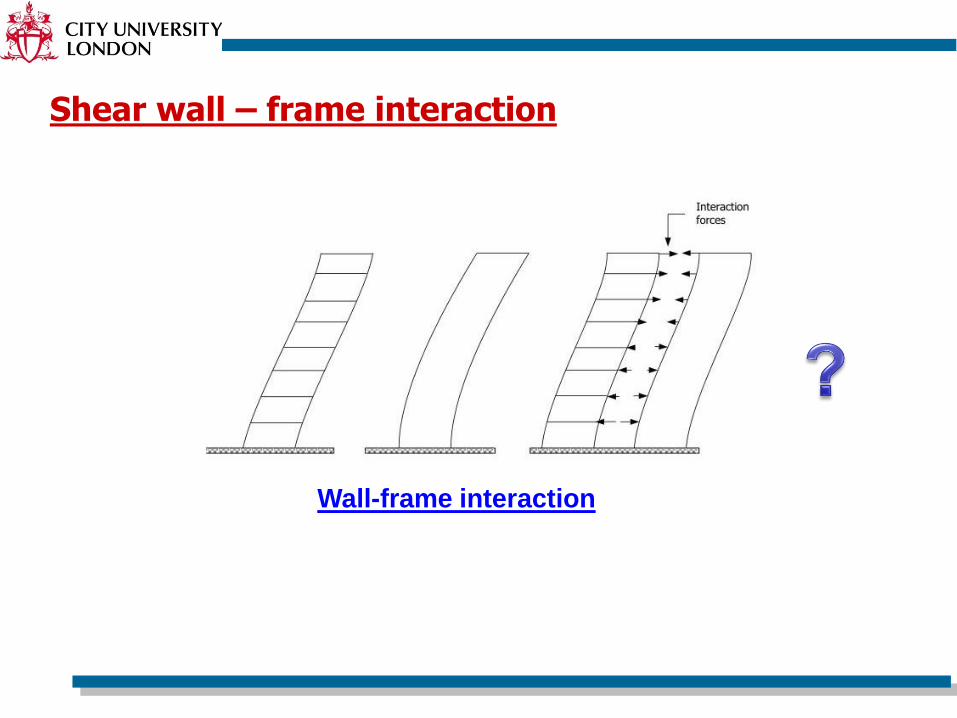
Shear wall – frame interaction
Wall-frame interaction
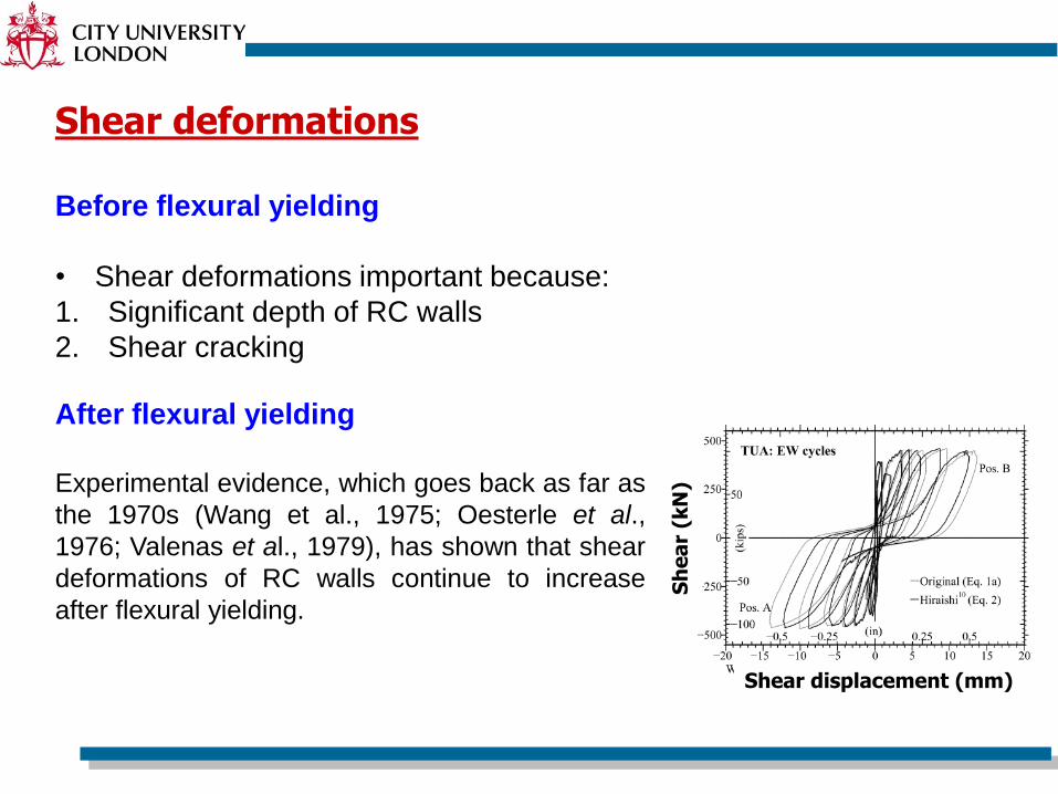
Before flexural yielding
• Shear deformations important because:
1. Significant depth of RC walls
2. Shear cracking
After flexural yielding
Experimental evidence, which goes back as far as
the 1970s (Wang et al., 1975; Oesterle et al.,
1976; Valenas et al., 1979), has shown that shear
deformations of RC walls continue to increase
after flexural yielding.
Shear deformations
Shear displacement (mm)S
he
ar
(kN
)
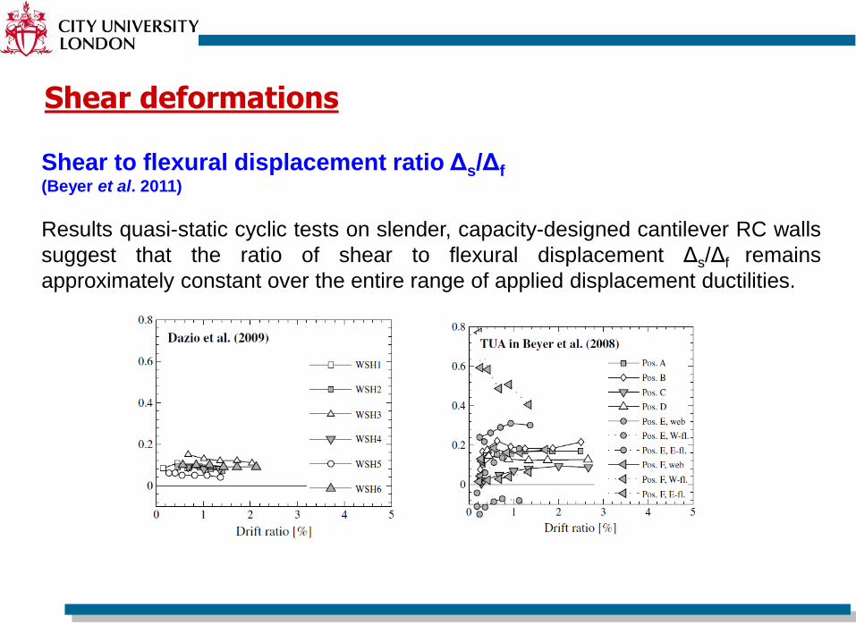
Shear to flexural displacement ratio Δs/Δf(Beyer et al. 2011)
Results quasi-static cyclic tests on slender, capacity-designed cantilever RC walls
suggest that the ratio of shear to flexural displacement Δs/Δf remains
approximately constant over the entire range of applied displacement ductilities.
Shear deformations
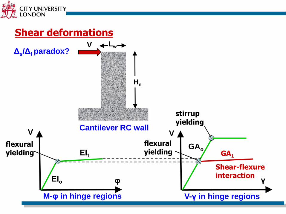
Δs/Δf paradox?
Shear deformations
Hn
LwV
V
γ
GAoGA1
flexural yielding
V-γ in hinge regions
V
φ
ΕΙ1
flexural yielding
M-φ in hinge regions
ΕΙο
stirrup yielding
Shear-flexure interaction
Cantilever RC wall
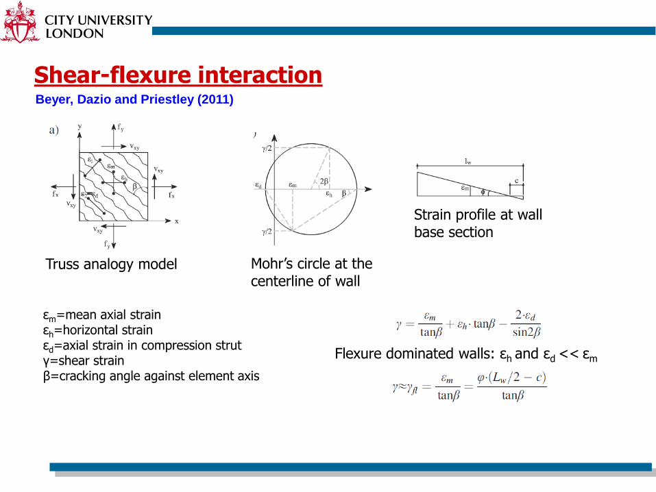
Shear-flexure interaction
Truss analogy model Mohr’s circle at the centerline of wall
Strain profile at wall base section
εm=mean axial strainεh=horizontal strainεd=axial strain in compression strutγ=shear strainβ=cracking angle against element axis
Flexure dominated walls: εh and εd << εm
Beyer, Dazio and Priestley (2011)
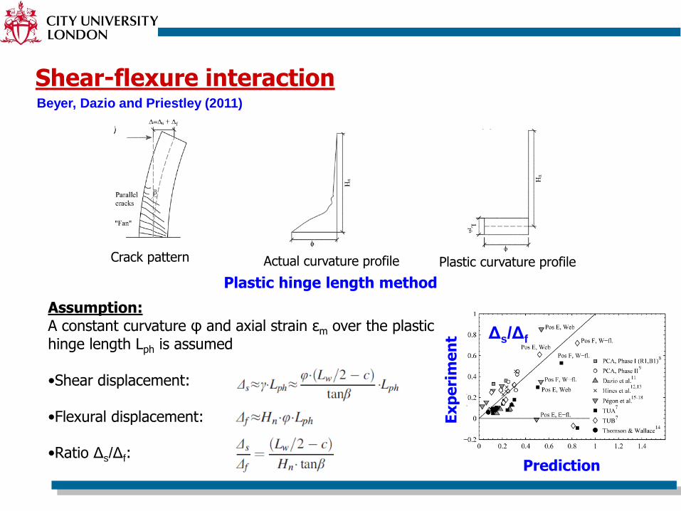
Shear-flexure interaction
Crack pattern Actual curvature profile
Plastic hinge length method
Assumption:A constant curvature φ and axial strain εm over the plastic hinge length Lph is assumed
•Shear displacement:
•Flexural displacement:
•Ratio Δs/Δf:
Plastic curvature profile
Prediction
Δs/Δf
Ex
pe
rim
en
t
Beyer, Dazio and Priestley (2011)
RC walls finite element models
• Inelastic response can be well captured by shell elements with advanced analytical methodologies accounting for the biaxial in-plane stress state in RC elements (e.g. MCFT by Vecchio and Collins 1986).
• Other models (e.g Wallace et al.) use macro-elements in which different elements are assigned a specific load-carrying mechanism (i.e. axial forces, moments and shears).
• In engineering practice, however, beam-column elements are typically employed.
– The vast majority of beam-column elements model only flexural and axial response.
– Beam-column models with shear-flexure interaction are very limited.
– Typically, a constant shear rigidity GA is assigned. This follows the misconception that GA is not influenced by flexural deformations.
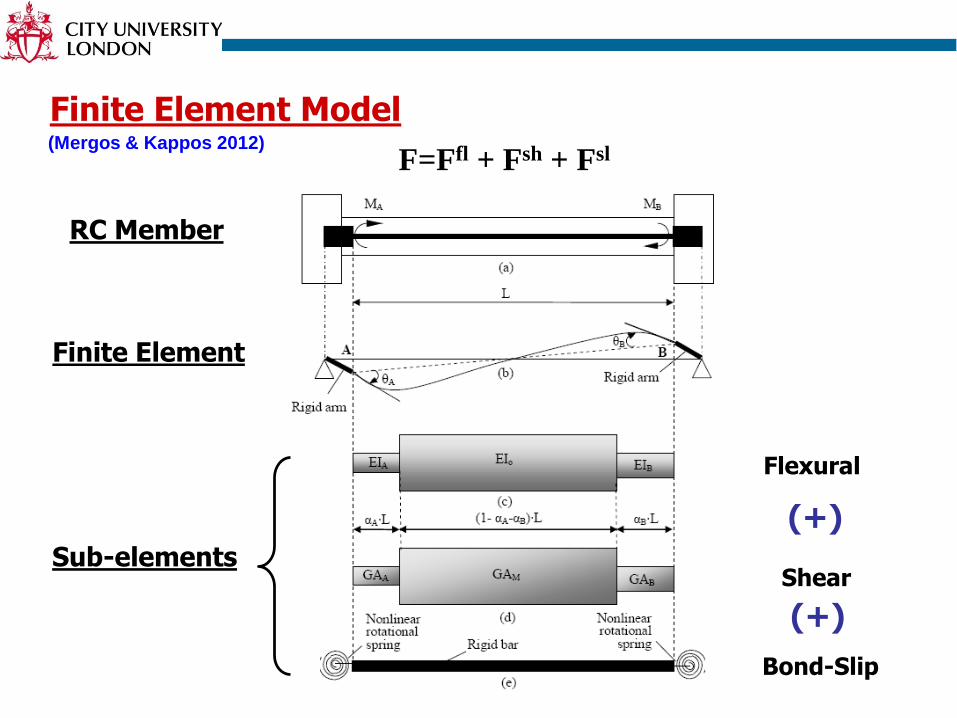
Finite Element Model
RC Member
Finite Element
Sub-elements
Bond-Slip
(+)
(+)
F=Ffl + Fsh + Fsl
Shear
Flexural
(Mergos & Kappos 2012)
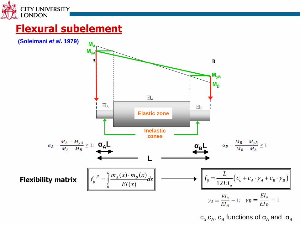
Flexural subelement
ΕΙΑ
ΕΙο
ΕΙΒ
A Β
MΑ
MB
MyB
MyA
L
αΑL αΒL (1- αΑ-αΒ)L
Elastic zone
Inelastic zones
ΜΑ
ΜyΑ
ΜB
ΜyB
dxxEI
xmxmf
L
BAfl
ij
0
)(
)()( 12
ij o A A B B
o
Lf c c c
EI Flexibility matrix
(Soleimani et al. 1979)
αAL
L
αBL
co,cA, cB functions of αA and αB
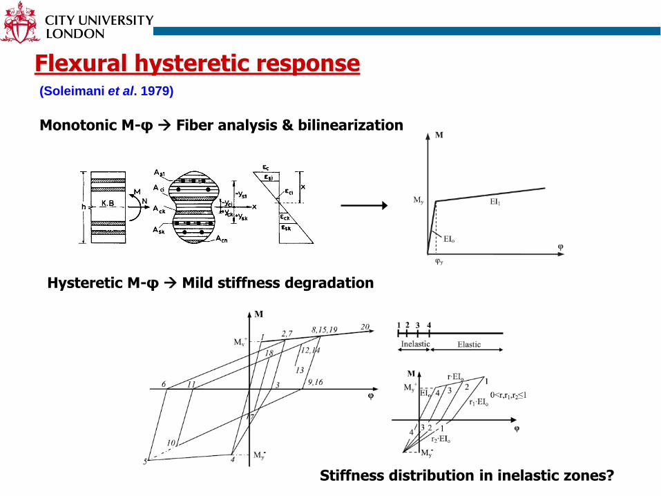
Flexural hysteretic response
Monotonic M-φ Fiber analysis & bilinearization
(Soleimani et al. 1979)
Hysteretic M-φ Mild stiffness degradation
Stiffness distribution in inelastic zones?
Shear subelement
(Mergos & Kappos 2012)
ΕΙΑ
ΕΙο
ΕΙΒ
A Β
MΑ
MB
MyB
MyA
L
αΑL αΒL (1- αΑ-αΒ)L
Elastic zone
Inelastic zones
ΜΑ
ΜyΑ
ΜB
ΜyB
•Flexibility matrix dxxGA
xvxvf
L
BAsh
ij
0
)(
)()(
V-γ without
interaction
V-γ with
interaction
•Moment diagram
•Flexural sub-element
•Shear sub-element
αAsL αBsL
L
GAA
GAM
GAB
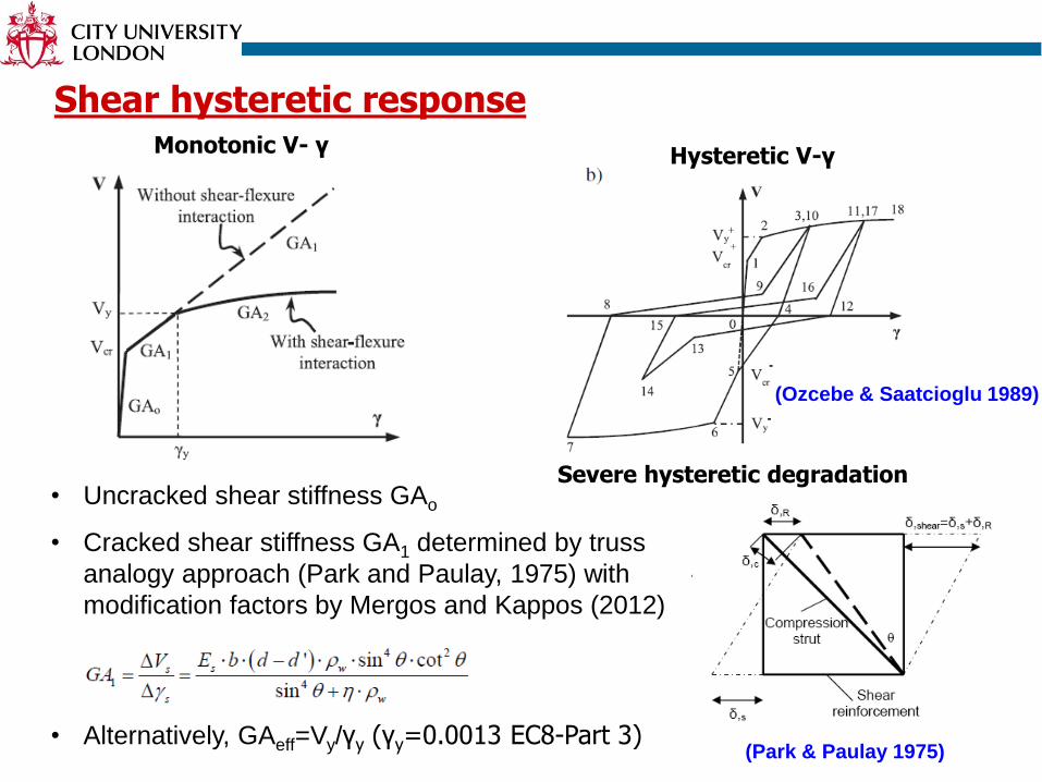
Shear hysteretic response
Severe hysteretic degradation
Monotonic V- γ Hysteretic V-γ
• Uncracked shear stiffness GAo
• Cracked shear stiffness GA1 determined by truss
analogy approach (Park and Paulay, 1975) with
modification factors by Mergos and Kappos (2012)
• Alternatively, GAeff=Vy/γy (γy=0.0013 EC8-Part 3)(Park & Paulay 1975)
(Ozcebe & Saatcioglu 1989)
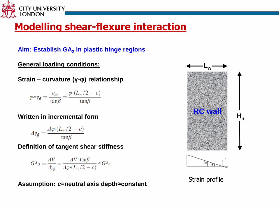
Modelling shear-flexure interaction
Aim: Establish GA2 in plastic hinge regions
General loading conditions:
Strain – curvature (γ-φ) relationship
Written in incremental form
Definition of tangent shear stiffness
Assumption: c=neutral axis depth≈constantStrain profile
Lw
RC wallHn
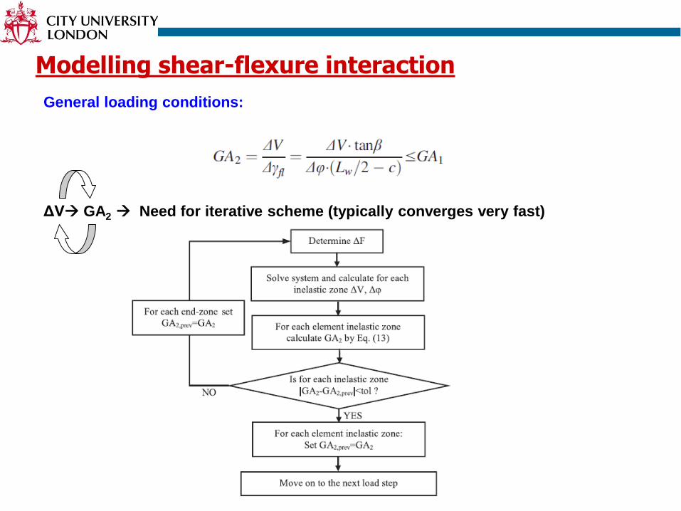
Modelling shear-flexure interaction
General loading conditions:
ΔV GA2 Need for iterative scheme (typically converges very fast)
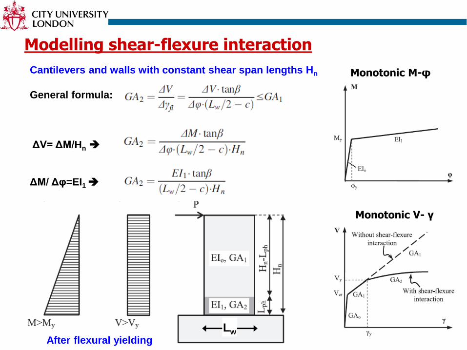
Modelling shear-flexure interaction
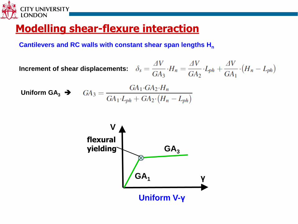
Cantilevers and walls with constant shear span lengths Hn
General formula:
ΔV= ΔM/Hn
ΔM/ Δφ=EI1
Lw
Monotonic V- γ
Monotonic M-φ
After flexural yielding
Modelling shear-flexure interaction
Cantilevers and RC walls with constant shear span lengths Hn
Increment of shear displacements:
Uniform GA3
V
γ
GA3
flexural yielding
Uniform V-γ
GA1
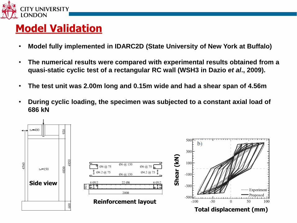
Model Validation
• Model fully implemented in IDARC2D (State University of New York at Buffalo)
• The numerical results were compared with experimental results obtained from a
quasi-static cyclic test of a rectangular RC wall (WSH3 in Dazio et al., 2009).
• The test unit was 2.00m long and 0.15m wide and had a shear span of 4.56m
• During cyclic loading, the specimen was subjected to a constant axial load of
686 kN
Side view
Total displacement (mm)
Sh
ea
r (k
N)
Reinforcement layout
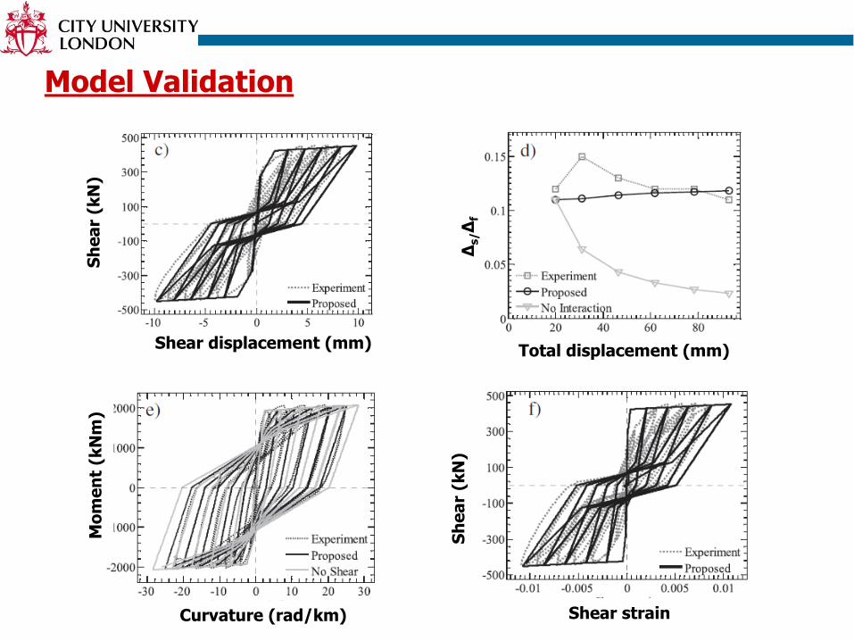
Model Validation
Shear displacement (mm)
Δs/Δ
f
Sh
ea
r (k
N)
Sh
ea
r (k
N)
Total displacement (mm)
Curvature (rad/km) Shear strain
Mo
me
nt
(kN
m)
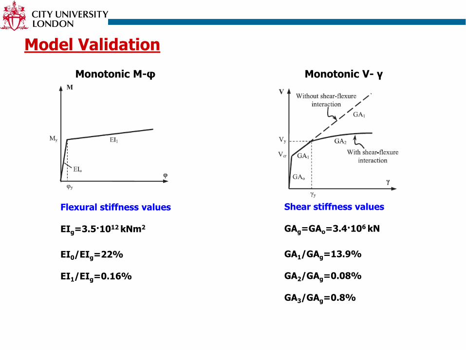
Model Validation
Flexural stiffness values
EIg=3.5·1012 kNm2
EI0/EIg=22%
EI1/EIg=0.16%
Monotonic M-φ
Shear stiffness values
GAg=GAo=3.4·106 kN
GA1/GAg=13.9%
GA2/GAg=0.08%
GA3/GAg=0.8%
Monotonic V- γ
Model Validation
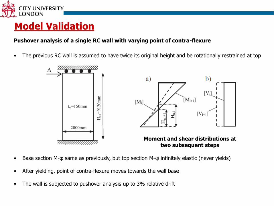
Pushover analysis of a single RC wall with varying point of contra-flexure
• The previous RC wall is assumed to have twice its original height and be rotationally restrained at top
• Base section M-φ same as previously, but top section M-φ infinitely elastic (never yields)
• After yielding, point of contra-flexure moves towards the wall base
• The wall is subjected to pushover analysis up to 3% relative drift
Moment and shear distributions at two subsequent steps
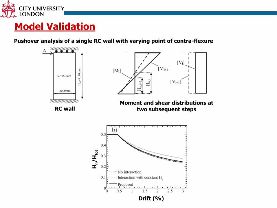
Model Validation
Pushover analysis of a single RC wall with varying point of contra-flexure
Moment and shear distributions at two subsequent steps
Drift (%)
Hn/H
tot
RC wall
Model Validation
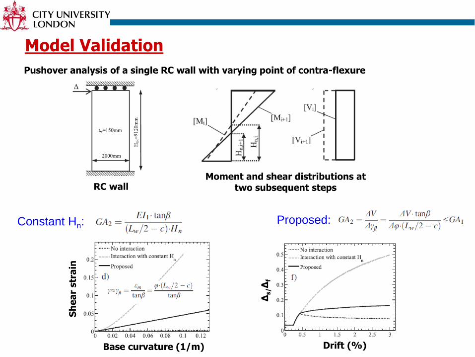
Pushover analysis of a single RC wall with varying point of contra-flexure
Moment and shear distributions at two subsequent stepsRC wall
Drift (%)Base curvature (1/m)
Sh
ea
r str
ain
Δs/Δ
f
Constant Hn: Proposed:
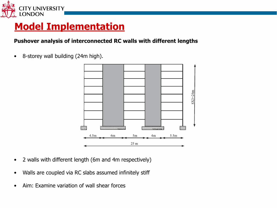
Model Implementation
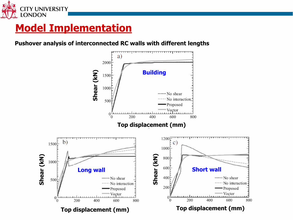
Pushover analysis of interconnected RC walls with different lengths
• 8-storey wall building (24m high).
• 2 walls with different length (6m and 4m respectively)
• Walls are coupled via RC slabs assumed infinitely stiff
• Aim: Examine variation of wall shear forces
Model Implementation
Pushover analysis of interconnected RC walls with different lengths
Top displacement (mm) Top displacement (mm)
Top displacement (mm)
Sh
ea
r (k
N)
Sh
ea
r (k
N)
Sh
ea
r (k
N)
Building
Long wall Short wall
Model Implementation
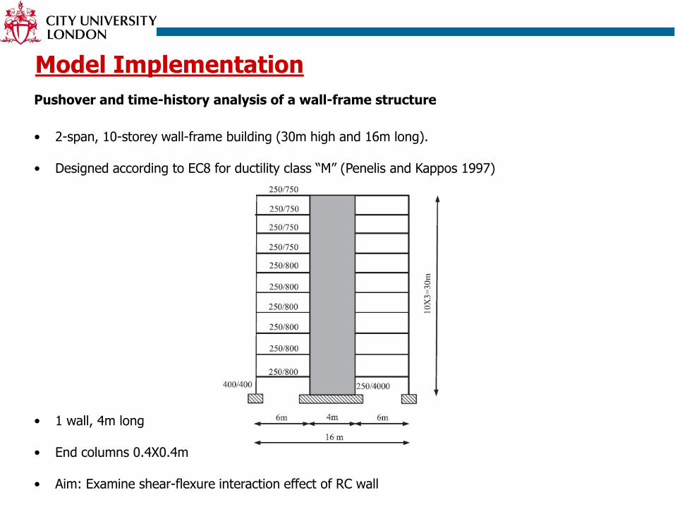
Pushover and time-history analysis of a wall-frame structure
• 2-span, 10-storey wall-frame building (30m high and 16m long).
• Designed according to EC8 for ductility class “M” (Penelis and Kappos 1997)
• 1 wall, 4m long
• End columns 0.4X0.4m
• Aim: Examine shear-flexure interaction effect of RC wall
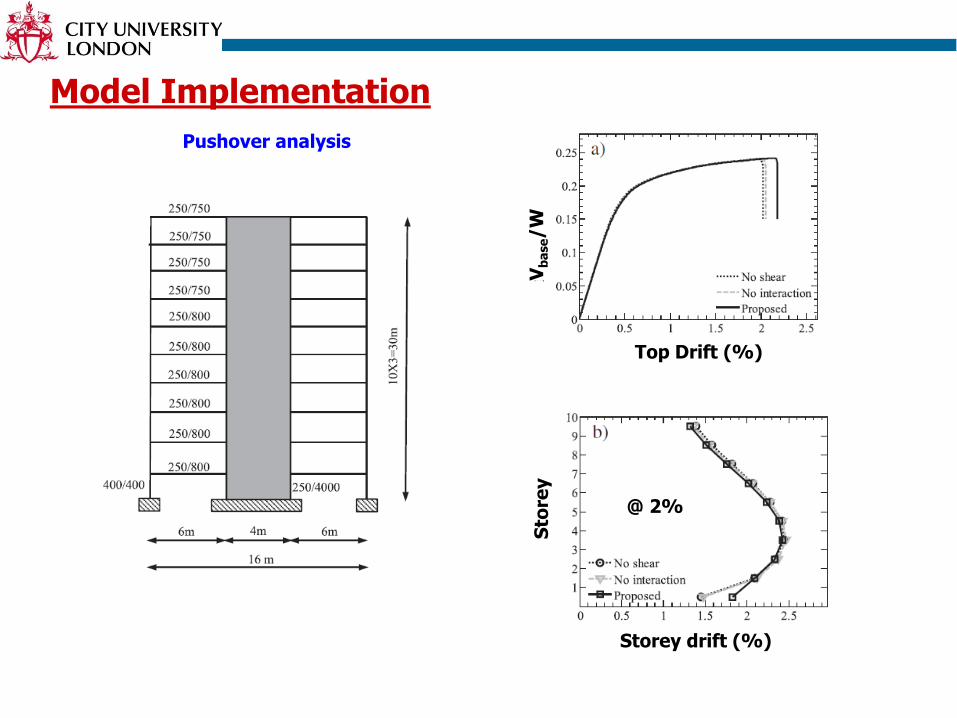
Model Implementation
Pushover analysis
Top Drift (%)
Vb
ase/W
@ 2%
Storey drift (%)
Sto
rey
Pushover analysis
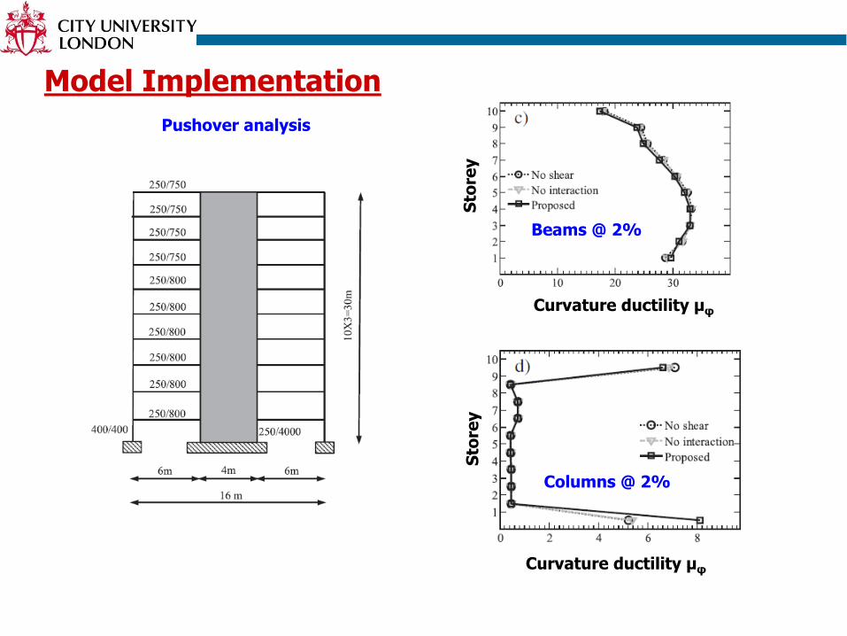
Model Implementation
Columns @ 2%
Curvature ductility μφ
Sto
rey
Curvature ductility μφ
Sto
rey
Beams @ 2%
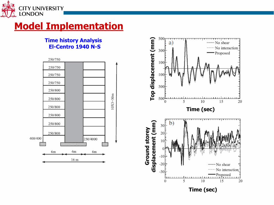
Time history AnalysisEl-Centro 1940 N-S
Model Implementation
Time (sec)
To
p d
isp
lace
me
nt
(mm
)
Time (sec)
Gro
un
d s
tore
y
dis
pla
ce
me
nt
(mm
)
Time history AnalysisEl-Centro 1940 N-S
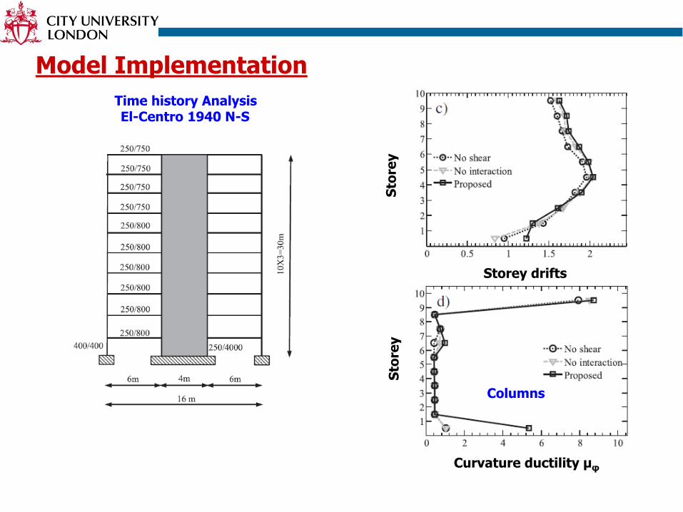
Model Implementation
Columns
Curvature ductility μφ
Sto
rey
Storey drifts
Sto
rey

Time history AnalysisEl-Centro 1940 N-S
Model Implementation
Columns
Curvature ductility μφ
Sto
rey
Storey drifts
Sto
rey
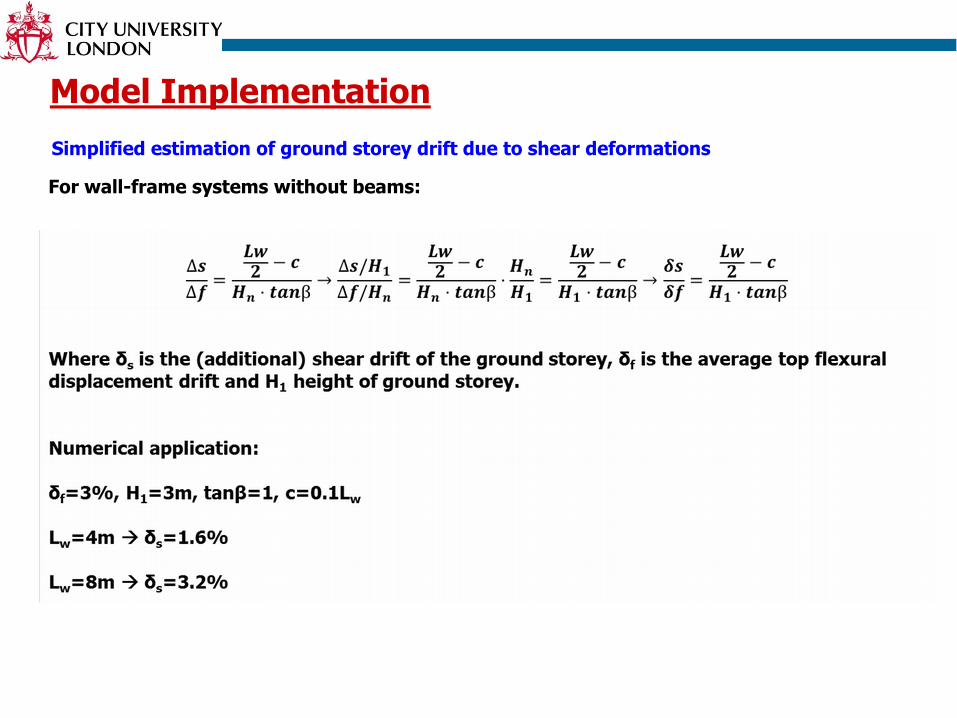
Model Implementation
Simplified estimation of ground storey drift due to shear deformations
For wall-frame systems without beams:
Conclusions
•Experimental evidence has shown that shear deformations of RC walls
continue to increase after flexural yielding. This is caused by shear-flexure
interaction effect.
•Beam-column elements used in practice to model RC walls ignore shear-
flexure interaction by assuming GA remains constant after flexural yielding
•A new beam-column element that accounts for shear-flexure interaction has
been developed and implemented in IDARC
•Validation studies have proven the accuracy of the proposed model
•Shear-flexure interaction is particularly important for predicting column
demands at the ground storey of tall wall-frame buildings
References
•Dazio, A., Beyer, K. and Bachmann, H. (2009). Quasi-static cyclic tests
and plastic hinge analysis of RC structural walls. Engineering
Structures 31, 1556-1571.
•Beyer, K., Dazio, A. and Priestley, M.J.N. (2011). Shear deformations of
slender RC walls under seismic loading. ACI Structural Journal 108:2,
167-177.
•Mergos, P.E. and Kappos, A.J. (2012). A gradual spread inelasticity
model for R/C beam-columns accounting for flexure, shear and
anchorage slip. Engineering Structures 44:1, 94-106.
•Mergos, P.E. and Beyer, K. (2014). Modelling shear-flexure interaction in
equivalent frame models of slender RC walls. Structural Design of Tall
and Special Buildings 23:15, 1171-1189.
Thank you for your kind attention…


![Beyer Escola Preparatoria Piano[1]](https://img.pdfslide.us/doc/110x75/54e9660a4a795922038b49dc/beyer-escola-preparatoria-piano1.jpg)