Embed Size (px)
Citation preview
P/N 20-07665-00 Rev K. © Hydro Systems Company, Inc. 2014 HydroSystemsCo.com Toll Free: 1.800.543.7184 1
Reference Manual LM-700 Series
Preface
This manual has been written and illustrated to present the basic installation, operation, and servicing instructions of the LM-700 Laundry Dispensing System. Guidelines will be suggested in reference to the preferred method of installation, however, the variety of equipment and the surrounding environment will dictate the actual installation of the LM-700.
MERCURY TL Laundry Dispensing System
Online and downloadable Product Manuals and Quick Start Guides are available at www.HydroSystemsCo.com Please check online for the latest version of this Reference Manual.
!WARNING:The LM-700 dispensing system is intended to be installed by experienced installers, in accordance with all applicable electrical and plumbing codes.
NOTE: Always use proper lockout tagout procedures when installing and servicing dispensing systems. Please disconnect all washer and dispenser power sources any time the dispenser cabinet is open.
All machine and dispenser power must be disconnected during installation and/or any time the dispenser cabinet is opened.
P/N 20-07665-00 Rev K. © Hydro Systems Company, Inc. 2014 HydroSystemsCo.com Toll Free: 1.800.543.7184 2
Table of Contents
1 Theory of Operation Overview ..........................................................................................................................................3 Automatic Mode...............................................................................................................................3 Push Button Mode ...........................................................................................................................3 Relay Mode ......................................................................................................................................4 2 Mechanical Installation Wall Mounting Unit ...........................................................................................................................4 Supply and Discharge Hoses ...........................................................................................................4 3 Electrical Installation Main Power ......................................................................................................................................5 Trigger Signal Wiring ........................................................................................................................5 Auto Formula Select Wiring .............................................................................................................5 4 User Mode Operation User Mode Screens .........................................................................................................................6 Formula Selection ............................................................................................................................6 Start Formula (Push Button Mode Only) ..........................................................................................6 View Load Counter...........................................................................................................................6 ID/Mode ...........................................................................................................................................6 Prime Pumps (when enabled) ..........................................................................................................7 Password Access to Program Mode ...............................................................................................7 5 Programming Introduction ......................................................................................................................................8 Key Descriptions ..............................................................................................................................8 Password Access to Program Mode ...............................................................................................8 Prime Pump “P-1”............................................................................................................................9 Clear Load Counter “CLr” ................................................................................................................9 Operating Parameters “oP’ ..............................................................................................................9 Lockout Period “LP” ........................................................................................................................9 Formula Program “F-1” ....................................................................................................................9 Pump Amount “P1A” .......................................................................................................................9 Delay Time “D1A” ............................................................................................................................9 Assign Pump “A1A” (only in Occurrence Mode) ..............................................................................9 Finish Program “Fin” ........................................................................................................................9 Filter Duration “Fd” ........................................................................................................................10 User Prime “uPr” ............................................................................................................................10 Password Edit “Pin” .......................................................................................................................10 Exit Program Mode “End” ..............................................................................................................10 6 Troubleshooting Dead Unit (No Display) Troubleshooting ........................................................................................11 7 Maintenance and Repair Spare Parts Listing .........................................................................................................................12 8 Maintenance and Specifications Dimensions ....................................................................................................................................13 Power Requirements ......................................................................................................................13 General Specifications ...................................................................................................................13 Limited Warranty ............................................................................................................................13 Limitation of Liability ......................................................................................................................13 Index

P/N 20-07665-00 Rev K. © Hydro Systems Company, Inc. 2014 HydroSystemsCo.com Toll Free: 1.800.543.7184 3
Theory of Operation
OverviewThe Mercury offers four operating modes for maximum flexibility in small OPL and Top Load washer laundry applications. Automatic Formula Selection may be used in all modes whenever a spare washer supply signal output is available that may be programmed to the second. The following sections describe each mode’s unique operation specifications in detail.
Automatic ModeAutomatic Mode is a basic mode of operation similar to Timer Mode in our Eclipse and Orion dispensers.Each trigger signal input number matches the corresponding pump number (i.e. trigger 1 = pump 1, trigger 2 = pump 2, etc.). Pumps can be delayed after trigger signals for occasions where pump delays are required to prevent dosing on dry linen, etc. Pump delay times are programmable in seconds. Pumps 1 and 2 have two product levels, A and B. The A level dispenses on the first occurrence of the trigger signal in a formula. The B level dispenses on the second occurrence of the same trigger signal within the same formula. Pump 3 only has one product level. The Pump Lockout feature, when turned on, prevents any unwanted pump activations due to false signals from washers that send noisy or multiple output supply signals. Loads are counted each time the highest pump number with an amount programmed (unique to each formula) is run. The Pump Lockout timer and (pumps 1 and 2) A/B levels will be reset 5 minutes after the count pump runs or the Lockout period ends, whichever comes first. If the load needs to be restarted for any reason, the dispenser wash formula may be terminated early by pressing the Enter key for two seconds.
Push Button ModePush Button Mode is intended for manual operation where the machine operator selects a formula andpresses the Enter key to start and run the dispenser wash formula. A dispenser wash formula consists ofup to 5 programmed pump amounts (1a, 1b, 2a, 2b, and 3 are the five programmable pump amounts fromthree physical pumps). Pump Delay times (programmed in minutes) stagger the programmed pump doses throughout the wash load. The Pump Lockout feature (programmed in minutes) prevents the machine operator from starting multiple doses in the same wash load. If the load needs to be restarted, the dispenser wash formula may be terminated early by pressing the Enter key for two seconds. Loads are counted each time the highest pump number with a programmed amount is run.
Occurrence ModeOccurrence Mode paces the dosing of products off the washer fill valves by counting each time the machine fills to identify the occurrence-sequence of machine steps. This mode of operation is ideally suited for machines with no chemical supply signal outputs, such as domestic style top load washers. While all three of the trigger signal inputs are active and may be used, typically only two will be used. Typical trigger signal wiring would be one of the available trigger signal inputs wired to one fill valve, and another trigger signal input to the other fill valve (typically the hot and cold fill valves). Since the dispenser responds to any of the trigger inputs, it does not matter which input goes to which fill valve. The dispenser counts the machine fill occurrences and runs pumps based on an assignment of the pumps to the machine step sequence.
NOTE: Careful attention must be paid when programming the signal Filter Duration time to account for anyspurious fills resulting from level and/or temperature controls in the washer. For more information, pleasesee section 4.8, Filter Duration.
A dispenser wash formula consists of up to 5 programmed pump amounts (1a, 1b, 2a, 2b, and 3 are the five programmable pump amounts from three physical pumps). Any of these available amounts may be programmed to any (up to 9) machine step. The Lockout feature is available to be sure that each programmed pump amount only runs one time per dispenser wash formula. The dispenser wash formula is terminated 5 minutes after the last pump programmed in a sequence runs, or the Lockout period (when on) ends, whichever comes first. If the load needs to be restarted for any reason, the dispenser wash formula may be terminated early by pressing the Enter key for two seconds.
P/N 20-07665-00 Rev K. © Hydro Systems Company, Inc. 2014 HydroSystemsCo.com Toll Free: 1.800.543.7184 4
Theory of Operation
Mechanical Installation
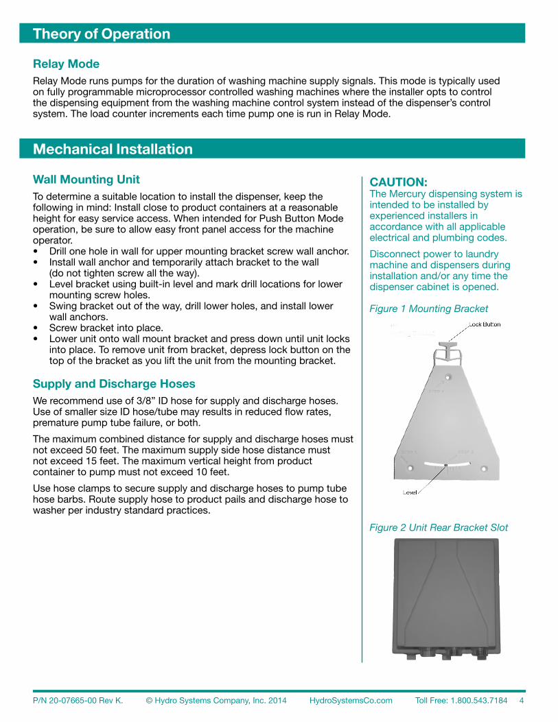
Relay ModeRelay Mode runs pumps for the duration of washing machine supply signals. This mode is typically usedon fully programmable microprocessor controlled washing machines where the installer opts to controlthe dispensing equipment from the washing machine control system instead of the dispenser’s controlsystem. The load counter increments each time pump one is run in Relay Mode.
Wall Mounting UnitTo determine a suitable location to install the dispenser, keep the following in mind: Install close to product containers at a reasonableheight for easy service access. When intended for Push Button Mode operation, be sure to allow easy front panel access for the machineoperator.• Drill one hole in wall for upper mounting bracket screw wall anchor.• Install wall anchor and temporarily attach bracket to the wall (do not tighten screw all the way).• Level bracket using built-in level and mark drill locations for lower mounting screw holes.• Swing bracket out of the way, drill lower holes, and install lower wall anchors.• Screw bracket into place.• Lower unit onto wall mount bracket and press down until unit locks into place. To remove unit from bracket, depress lock button on the top of the bracket as you lift the unit from the mounting bracket.
Supply and Discharge HosesWe recommend use of 3/8” ID hose for supply and discharge hoses. Use of smaller size ID hose/tube may results in reduced flow rates, premature pump tube failure, or both.
The maximum combined distance for supply and discharge hoses must not exceed 50 feet. The maximum supply side hose distance must not exceed 15 feet. The maximum vertical height from productcontainer to pump must not exceed 10 feet.
Use hose clamps to secure supply and discharge hoses to pump tube hose barbs. Route supply hose to product pails and discharge hose to washer per industry standard practices.
CAUTION:The Mercury dispensing system isintended to be installed by experienced installers in accordance with all applicable electrical and plumbing codes.
Disconnect power to laundrymachine and dispensers duringinstallation and/or any time thedispenser cabinet is opened.
Figure 1 Mounting Bracket
Figure 2 Unit Rear Bracket Slot
P/N 20-07665-00 Rev K. © Hydro Systems Company, Inc. 2014 HydroSystemsCo.com Toll Free: 1.800.543.7184 5
Electrical Installation
The Mercury is available in two different wiring versions: terminal block,or wiring cable. The following instructions apply to cable versions.Terminal Block versions include an additional wiring information labeladjacent to the terminal blocks inside the unit enclosure.
The Mercury includes two separate wiring cables for Main Power and Input Trigger Signal connections. These cables may route through either one or two conduit fittings, as required.
Main PowerMain Power is a universal power input that accepts any AC voltage from 90-249 VAC, 50/60 Hz. Typical sources include a wall outlet, or washing machine incoming power terminals. For wall outlet connections use a wall plug, sourced locally, that fits outlets in your region. Main Power Cable color coding is as follows: Blue + Brown 90-249 VAC, 50/60 Hz.
NOTE: In cases where a Neutral wire exists, connect Neutral tothe Blue wire.
Green with yellow stripe is Earth Ground.
Trigger Signal WiringAll trigger signal inputs are optically isolated high impedance input circuits. Washer supply signal voltages may range from 24-249 VAC, 50/60 Hz (20 mA maximum draw) or 12-24 VDC (5 mA maximum draw) that accommodate the range typically found in most washing machines. Each signal input connects to a pair of signal input wires (solid color and white with colored stripe). In cases where the washing machine has a singlecommon for supply signals, connect all the signal input common wires (white with colored stripes) to the machine’s signal common wiring location. In Automatic or Relay Mode trigger inputs match pump numbers (i.e. trigger 1 = pump 1, etc.). In Occurrence Mode connect wire pairs from each machine fill valve to two trigger inputs (it does not matter which two of the three available trigger inputs are used for Occurrence Mode). Signal Input wire colors are as follows:Trigger Signal 1 = BlackSignal Common 1 = White w/Black StripeTrigger Signal 2 = BrownSignal Common 2 = White w/Brown StripeTrigger Signal 3 = RedSignal Common 3 = White w/Red Stripe
Auto Formula Select WiringInput specifications are the same as trigger inputs. The Auto Formula Select signal must be programmable to the second on the washing machine control system. Program the washer to send this signal at the start of the wash load (prior to any chemical supply signals) for a duration of 2 seconds times the desired formula number (i.e. for formula 2 program for 2s * F2 = 4 seconds signal time).Auto Formula Select input wire colors are as follows:Auto Formula Select Signal = OrangeAuto Formula Select Signal Common = White w/Orange
CAUTION:The Mercury dispensing system is intended to be installed by experienced installers in accordance with all applicable electrical and plumbing codes. All laundry machine and dispenser power is to be disconnectedduring installation and/or any timethe dispenser cabinet is opened.
CAUTION:Always verify all voltage sources with a meter.
NOTE:Failure to use watertight conduit for electrical cables will impair water resistance of the unit enclosure.
P/N 20-07665-00 Rev K. © Hydro Systems Company, Inc. 2014 HydroSystemsCo.com Toll Free: 1.800.543.7184 6
User Mode Operation
The Mercury dispensers four modes of operation are described in this section.
Automatic Mode runs each pump program (program = delay time + run time) upon qualified input to therespective signal input. When on (not set to 000), the Lockout Timer begins at start of first pump program(beginning of delay time). During this lockout period, no pump amount may run more than once regardless of the number of times the signal input occurs. Display indicates signal status, pumps running, and lockout status. Machine operator selects desired formula number with the Scroll key. Auto Formula Select is always active, but may be overridden by machine operator input.
Push Button Mode relies on a user push button press to start the wash formula program. Auto Formula Select is always active, but may be overridden by machine operator input. The machine operator selects the formula number with the Scroll key, and then starts the wash formula program by pressing and releasing the Enter key for less than 2 seconds. Pumps run as programmed via programmed delay and run times. During the lockout time, all button presses to start the formula program are ignored except, Password input. The display indicatespumps running and lockout status.
Occurrence Mode is an alternate automatic logic where signals from input numbers 1, 2 and 3 act as asingle logic input signal. Signal occurrences are counted (simultaneous input signals count as one signal occurrence) to determine when each pump runs, based on pump-assignments in the Assign Pump “A1A” screen in the programming menu. Pumps 1 and 2 have two programmable amounts, A and B, which are treated in Occurrence Mode as separate pump programs. Display indicates signal status, pumps running, and lockout status. Auto Formula Select is always active, but may be overridden by machine operator input.
Relay Mode requires no machine operator interaction since all dispensing system control is turned over to the washing machine control system.
NOTE: Password input and/or power failure resets the lockout timer and ends the wash load in all modes.
User Mode Menu ScreensUse the Next key to step through all available User Mode menu screens. The display will revert to the User ModeHome Screen after 30 seconds of inactivity.
Formula SelectionFrom the Home Screen, press the Scroll key to select programmed formulas (1-4).
NOTE: Formulas with no amounts programmed may not be selected.
Start Formula (Push Button Mode Only)From the Home Screen press and release the Enter key for less than 2 seconds to trigger manual dispensing.
NOTE: To terminate wash formula before end of lockout period press and hold the Enter key longer than 2 seconds, release, and wait 30 seconds for screen to revert to idle screen.
View Load CounterFrom the Home Screen press the Next key once to display “L”. Load counter (all formulas) will toggle between “L” and load count since last clear.
ID/ModeFrom the Home Screen press the Next key twice to display the operating firmware ID number and currently selected operating mode. The first two digits indicate a firmware ID number we may ask you when troubleshooting. The right digit indicates the current Operating Parameter (oP) selection (1= Automatic, 2 = Push Button, 3 = Occurrence, and 4 = Relay).
P/N 20-07665-00 Rev K. © Hydro Systems Company, Inc. 2014 HydroSystemsCo.com Toll Free: 1.800.543.7184 7
User Mode Operation
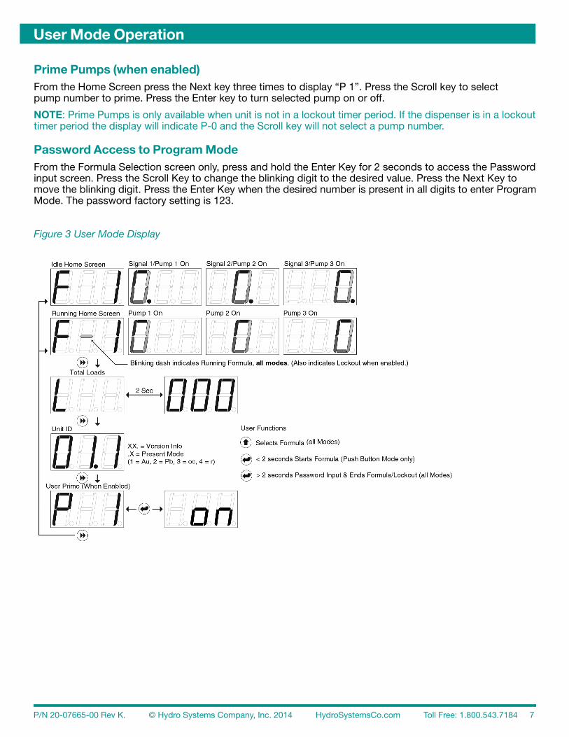
Prime Pumps (when enabled)From the Home Screen press the Next key three times to display “P 1”. Press the Scroll key to selectpump number to prime. Press the Enter key to turn selected pump on or off.
NOTE: Prime Pumps is only available when unit is not in a lockout timer period. If the dispenser is in a lockout timer period the display will indicate P-0 and the Scroll key will not select a pump number.
Password Access to Program ModeFrom the Formula Selection screen only, press and hold the Enter Key for 2 seconds to access the Password input screen. Press the Scroll Key to change the blinking digit to the desired value. Press the Next Key to move the blinking digit. Press the Enter Key when the desired number is present in all digits to enter Program Mode. The password factory setting is 123.
Figure 3 User Mode Display
P/N 20-07665-00 Rev K. © Hydro Systems Company, Inc. 2014 HydroSystemsCo.com Toll Free: 1.800.543.7184 8
Programming
IntroductionUse the menu screen illustrations as a guide when learning to program the Mercury. We suggest that you power up a unit and become familiar with the programming steps in a quiet environment, with the manual, prior to the first installation. Use the Next key to move to all available main menu screens in Program Mode.
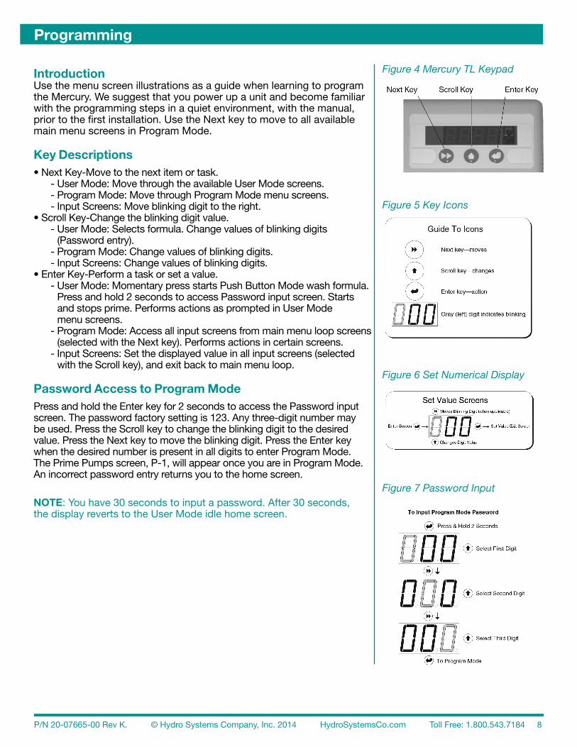
Key Descriptions• Next Key-Move to the next item or task. - User Mode: Move through the available User Mode screens. - Program Mode: Move through Program Mode menu screens. - Input Screens: Move blinking digit to the right.• Scroll Key-Change the blinking digit value. - User Mode: Selects formula. Change values of blinking digits
(Password entry). - Program Mode: Change values of blinking digits. - Input Screens: Change values of blinking digits.• Enter Key-Perform a task or set a value. - User Mode: Momentary press starts Push Button Mode wash formula.
Press and hold 2 seconds to access Password input screen. Starts and stops prime. Performs actions as prompted in User Mode menu screens.
- Program Mode: Access all input screens from main menu loop screens (selected with the Next key). Performs actions in certain screens.
- Input Screens: Set the displayed value in all input screens (selected with the Scroll key), and exit back to main menu loop.
Password Access to Program ModePress and hold the Enter key for 2 seconds to access the Password input screen. The password factory setting is 123. Any three-digit number may be used. Press the Scroll key to change the blinking digit to the desired value. Press the Next key to move the blinking digit. Press the Enter key when the desired number is present in all digits to enter Program Mode. The Prime Pumps screen, P-1, will appear once you are in Program Mode. An incorrect password entry returns you to the home screen.
NOTE: You have 30 seconds to input a password. After 30 seconds, the display reverts to the User Mode idle home screen.
Figure 4 Mercury TL Keypad
Figure 5 Key Icons
Figure 6 Set Numerical Display
Figure 7 Password Input

P/N 20-07665-00 Rev K. © Hydro Systems Company, Inc. 2014 HydroSystemsCo.com Toll Free: 1.800.543.7184 9
Programming
Prime Pump “P-1”Press the Scroll Key to select pump number. Press the Enter Key to turn pump on. Press the Enter Keyagain to turn the pump off. Pump prime automatically ends after 5 minutes, if pump is left on.
Clear Load Counter “CLr”Every two seconds, the screen alternates between CLr and load count (all formulas). Press and hold theEnter key for two seconds to reset the Load Counter.
Operating Parameters “oP”Every two seconds, the screen alternates between oP and the current selection. Press the Enter key toselect the desired mode of operation: Au (Automatic), Pb (Push Button), oc (Occurrence), or r (Relay).
NOTE: The four operating modes, Lockout Period, and other related operational details are described in more detail under Theory Of Operation.
Lockout Period “LP”Press the Enter key to display/edit Lockout Period value in minutes. Input method is the same as Password input. 00.0 = Lockout off. The range of adjustment is 00.0-99.9 minutes.
NOTE: In Occurrence and Push Button Modes, the programmed Lockout Period must be longer than the totaltime of all programmed pump run times and delay times. The Lockout Period should approximate the washer cycle time for a complete load.
Formula Program “F-1”Press Scroll key to select the formula number (1-4) you wish to program. Press the Enter Key to move to the Program Formulas menu loop for the selected formula number. This menu loop is not available in Relay Mode. If data is input in this loop and Relay Mode is later selected, all values will be retained for later use if Relay Mode is cancelled. Use the Next key to step through all available menu screens in this loop.
Pump Amount “P1A”Every two seconds, the screen alternates between the stored run time (in seconds) for the selected pumpnumber and Pxx. Press the Scroll key to select the desired pump number (P1A, P1B, P2A, P2B, and P3 are the available pump numbers). To set a pump run time, press and hold the Enter key for two seconds to start the pump (display will increment seconds and pump will run). When desired time/volume is reached, press the Enter key again to stop the pump and set the value. Repeat for all desired pumps. The adjustment range is 000-240 seconds.
Delay Time “D1A”Press the Scroll key to select the pump number (P1A, P1B, P2A, P2B, and P3) to be delayed. Press theEnter key and input delay time in the same manner as Password input. In Push Button Mode, programDelay Times in minutes (display will read 00.0). In all other modes, Delay Times are seconds (displaywill read 000).
Assign Pump “A1A” (only in Occurrence Mode)Assigns pump numbers to signal sequence occurrences. At the A1A screen, press the Scroll key to select the pump number (P1A, P1B, P2A, P2B, and P3) you wish to assign to a machine step occurrence. Press the Enter key to access occurrence input screen (oc). Press the Scroll key to assign the previously selected pump number to the machine step occurrence (1-9) in which you desire that pump to run. Press the Enter key to set this assignment and return to the formula programming sub-menu loop. Repeat for all pumps/occurrences.
Finish Program “Fin”Press the Enter key at this screen to return to the F-1 formula number selection screen in the main menu loop.

P/N 20-07665-00 Rev K. © Hydro Systems Company, Inc. 2014 HydroSystemsCo.com Toll Free: 1.800.543.7184 10
Programming
Filter Duration “Fd”Press the Enter key to view/set Signal Filter Duration (same input method as Password input). The availablerange is 0-19 seconds; the default is 3 seconds).
NOTE: In Occurrence Mode, set the Filter Duration time long enough to filter out excess fill valve signals that may occur as the washer level control calls for more water, etc. Automatic and Relay modes typically use the default setting.
User Prime “uPr”Every 2 seconds, the screen alternates between UPr and current User Prime setting (on or off). Press theEnter Key to change this setting.
Password Edit “Pin”Any three-digit number may be input. Press the Scroll Key to change the blinking digit to the desired value. Press the Next Key to move the blinking digit. Repeat for all digits and press the Enter Key when the desired password is present.
NOTE: Note any password changes! Access to Program Mode is not available if the password is lost!
Exit Program Mode “End”Press the Enter key to exit Program Mode and return to User Mode.
NOTE: To clear all values and restore factory settings, press and hold the Scroll key for two seconds, then press the Enter key (while still pressing the Scroll key). “FAC” will appear to indicate that you have restored factory settings and cleared the dispenser’s memory (including counter reset to zero). Press the Enter key again to return to User Mode.
Figure 8 Program Mode Screens Figure 9 Key Icons
Figure 10 Set Numerical Display

P/N 20-07665-00 Rev K. © Hydro Systems Company, Inc. 2014 HydroSystemsCo.com Toll Free: 1.800.543.7184 11
Dead Unit (No Display) Troubleshooting1. Verify Main Power (between 90 VAC and 249 VAC, 50/60 Hz) is present on Main Power Cable (or Terminals) and Power Switch (located behind cover in upper left corner) is On. Yes? Go to step 2. No? Restore Main Power source.
2. With a volt meter capable of reading AC voltages between 90VAC and 249 VAC, and DC voltages around 20 VDC to 30 VDC, perform the following measurements on the Power Supply PCB:
2a. Recheck Main Power source, if Main Power present, replace Logic PCB.
Troubleshooting
Problem Possible Cause Solution
No voltage to main power terminals
1. Tripped breakers or blown fuses at power source
1. Reset breakers or replace fuse at power source
2. Main power wires 2. Check connections at plug or washer power terminals
Voltage at main power terminals, but LED displayis not lit (see additional troubleshooting info above)
1. Power supply failure 1. Replace power supply
2. Damaged logic circuit board 2. Replace logic circuit board
Pumps run slowly or not at all1. Pumps not plugged in properly 1. Verify pump electrical connectors are
plugged in properly
2. Pump failure 2. Replace failed pump
Password will not access program mode 1. Password has been changed 1. Call Hydro Systems Customer Service for new Logic PCB
Pump runs but will not deliver product
1. Squeeze tube failure 1. Replace squeeze tube
2. Product tubing plugged 2. Replace product tubing
3. Pump roller failure 3. Replace pump roller
Poor results
1. Squeeze tube failure 1. Replace squeeze tube
2. Product tubing plugged 2. Replace product tubing
3. Pump roller failure 3. Replace pump roller
Dispenser not dispensing upon request from washer
1. Incorrect Operating Mode (Op) selected from programming menu
1. Select appropriate Operating Mode under (Op) in the programming menu
2. Signal wires are loose or wired incorrectly 2. Check signal wiring to washer
P/N 20-07665-00 Rev K. © Hydro Systems Company, Inc. 2014 HydroSystemsCo.com Toll Free: 1.800.543.7184 12
Maintenance and Repair
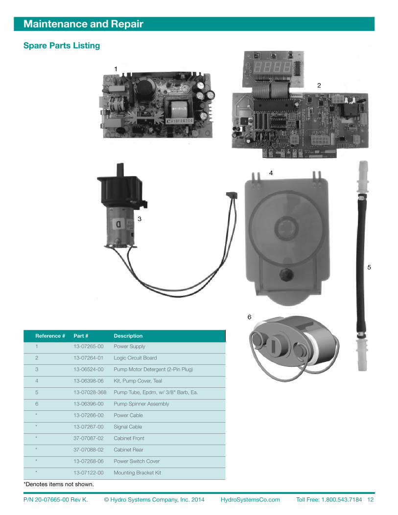
Spare Parts Listing
Reference # Part # Description
1 13-07265-00 Power Supply
2 13-07264-01 Logic Circuit Board
3 13-06524-00 Pump Motor Detergent (2-Pin Plug)
4 13-06398-06 Kit, Pump Cover, Teal
5 13-07028-368 Pump Tube, Epdm, w/ 3/8" Barb, Ea.
6 13-06396-00 Pump Spinner Assembly
* 13-07266-00 Power Cable
* 13-07267-00 Signal Cable
* 37-07087-02 Cabinet Front
* 37-07088-02 Cabinet Rear
* 13-07268-06 Power Switch Cover
* 13-07122-00 Mounting Bracket Kit
*Denotes items not shown.

P/N 20-07665-00 Rev K. © Hydro Systems Company, Inc. 2014 HydroSystemsCo.com Toll Free: 1.800.543.7184 13
Routine maintenance includes keeping the dispenser wiped clean with a damp cloth and periodic Pump Tube replacement.
NOTE: In the event of pump tube failure, always clean all pump part surfaces with a damp cloth to prevent possible damage from chemical attack.
DimensionsSize: 8" (20.3 cm) wide X 9" (22.2 cm) high X 6" (150.4 cm) deepWeight: 5.5 lbs. (2.47 kilos)Temperature: 120° F Maximum
Power RequirementsTotal amperage draw during operation is: 90 to 249 VAC, 50/60 Hz. 1.0 amps (max).
General SpecificationsPump Flow Rate 6.0 oz/minute (177 mls/minute)
NOTE: All specifications subject to change without notice.
Limited WarrantySELLER warrants solely to BUYER the Products will be free from defects in material and workmanshipunder normal use and service for a period of one year from the date of completion of manufacture. Thislimited warranty does not apply to (a) hoses; (b) and products that have a normal life shorter than one year; or(c) failure in performance or damage caused by chemicals, abrasive materials, corrosion, lightening, impropervoltage supply, physical abuse, mishandling or misapplication. In the event the Products are altered orrepaired by BUYER without SELLER’S prior written approval, all warranties will be void.
NO OTHER WARRANTY, ORAL, EXPRESS OR IMPLIED, INCLUDING ANY WARRANTY OF MERCHANTABILITY OR FITNESS FOR ANY PARTICULAR PURPOSE, IS MADE FOR THESE PRODUCTS,AND ALL OTHER WARRANTIES ARE HEREBY EXPRESSLY EXCLUDED.
SELLER’S sole obligation under this warranty will be, at SELLER’S option, to repair or replace F.O.B.SELLER’S facility in Cincinnati, Ohio any Products found to be other than as warranted.
Limitation of LiabilitySELLER’S WARRANTY OBLIGATIONS AND BUYERS REMEDIES ARE SOLELY AND EXCLUSIVELY AS STATED HEREIN. SELLER SHALL HAVE NO OTHER LIABILITY, DIRECT OR INDIRECT, OF ANY KIND, INCLUDING LIABILITY FOR SPECIAL, INCIDENTAL, OR CONSEQUENTIAL DAMAGES OR FOR ANY OTHER CLAIMS FOR DAMAGE OR LOSS RESULTING FROM ANY CAUSE WHATSOEVER, WHETHER BASED ON NEGLIGENCE, STRICT LIABILITY, BREACH OF CONTRACT OR BREACH OF WARRANTY.
Maintenance and Specifications
P/N 20-07665-00 Rev K. © Hydro Systems Company, Inc. 2014 HydroSystemsCo.com Toll Free: 1.800.543.7184 14
Index
AAuto Formula Select Wiring ...................... 5Automatic Mode ................................... 3, 6 CClear Load Counter “CLr” ...................... 10Counting Loads ........................................ 3DDelay Time “D1A” ..................................... 9EElectrical Installation ................................. 5Exit Program Mode “End” ...................... 10FFilter Duration ........................................... 3Filter Duration “Fd” ................................. 10Finish Program “Fin” ................................ 9Formula Program “F-1” ............................ 9HHoses ....................................................... 4KKeypad ..................................................... 8LLoads counting .............................................. 3Lockout functions .............................................. 3 operation ..........................................6-7 programming ....................................... 9Lockout Timer resetting .............................................. 3MMain Power ........................................ 5, 11Mechanical Installation ............................. 4Mounting Bracket ..................................... 4NNumerical Displays Explained. See alsoProgramming; User Mode OperationOOccurrence Mode .................... 3, 5-6, 9-10Operating Modes .................................. 3, 9Operating Parameters “oP” ...................... 9PPassword access to program mode ...........7-8, 10 edit “Pin” ........................................... 10Password Edit “Pin” ............................... 10Power Failure ............................................ 6Prevent false activation of pumps ............ 3Prime Pump “P-1” .................................... 9Product levels ........................................... 3Program Mode Screens ......................... 10Programming .......................................8-10Pump delays .................................................. 3 numbers .......................................... 5, 9 product levels A & B ............................ 3 run time, setting .............................. 6, 9Pump Amount “P1A ................................. 9Push Button Mode .................... 3-4, 6, 8-9RRelay Mode ................................. 4-6, 9-10 formula programming not available .... 9Restart Loads ........................................... 3SSignal Wiring instructions .......................................... 5Supply and Discharge Hoses ................... 4TTrigger Signal Input Number..................... 3Trigger Signal Wiring ................................ 5
UUser Mode Operation ............................6-7User Prime “uPr” .................................... 10WWall Mounting Unit ................................... 4Wash Formula early termination .............................. 3, 6 programming ................................... 3, 6Wiring instructions .......................................... 5