Embed Size (px)
Citation preview

www.resourcedm.com
PR0150-XXX
Mercury Coldroom Panel
Installation & User Guide
UK OFFICE
Resource Data Management Ltd
80 Johnstone Avenue,
Hillington Industrial Estate,
Glasgow, Scotland, G52 4NZ, UK
+44(0)141 810 2828
US OFFICE
Resource Data Management Inc
100 North Sixth Street,
Suite 820C,
Minneapolis, MN 55403, USA
Tel +1 612 354 2923
Fax +1 612 208 0922
Resource Data Management
Revision 7.1b Page 2 of 31
Mercury Coldroom Panel Installation Guide
www.resourcedm.com
Warning
Please Note The specifications of the product detailed on this Set-Up Guide may change without notice. RDM Ltd. shall not be liable for errors or for incidental or consequential damages, directly and indirectly, in connection with the furnishing, performance or misuse of this product or document.
Ensure that all power is switched off before installing or maintaining this product
Table of Contents:
THE MERCURY RANGE ....................................................................................................................................4
Networks .............................................................................................................................................................4 Configuration .....................................................................................................................................................4 Front Panel Features .........................................................................................................................................5 Connections .......................................................................................................................................................6
Mains Input and Outputs ..................................................................................................................................6 Probe and Alarm inputs....................................................................................................................................7 Internal Cable Diagram for LLV type ................................................................................................................8 Internal Cable Diagram for EEV type ...............................................................................................................8 RS485 Network Connection. ............................................................................................................................8 Input/Output Allocation Tables .........................................................................................................................9 Inputs and Outputs ...........................................................................................................................................9
Digital Inputs ......................................................................................................................................................9 Setting up the Panel ....................................................................................................................................... 10
Setup through the keypad ............................................................................................................................. 10 Setup Function Menu .................................................................................................................................... 10 Pin Menu Access .......................................................................................................................................... 10
Recommended set-up method ...................................................................................................................... 11 rtc. Real time clock (This will automatically synchronise on network systems) ............................................ 11 type. Set/view controller type ........................................................................................................................ 11 Unit. Set/view temperature unit and Probe type ........................................................................................... 11 Probe Types .................................................................................................................................................. 11 Display........................................................................................................................................................... 11 PArA. Set/view parameters (This can be achieved at the network front end) .............................................. 12
Parameter Table for Compressor/LLV type: ................................................................................................ 12 Parameter table for EEV Type ....................................................................................................................... 13 Parameters Description ................................................................................................................................. 15 Load Shedding ................................................................................................................................................ 18 EEV Control Using Pressure ......................................................................................................................... 18
Mercury Switch (PR0018-PHI) ...................................................................................................................... 18 Remote pressure Direct from a Plant Pack Controller .................................................................................. 18 Maximum Operating Pressure ...................................................................................................................... 18
Network Configuration ................................................................................................................................... 19 485 Legacy module ....................................................................................................................................... 19 IP Futura module ........................................................................................................................................... 20
Viewing ............................................................................................................................................................ 21 Input/Output table for Coldroom Panel with Compressor/LLV option ........................................................... 21 Input/Output table for Coldroom Panel with EEV option ............................................................................... 22 Switched Resistor Values ............................................................................................................................. 23
Alarm Messages ............................................................................................................................................. 23 Network Alarms .............................................................................................................................................. 23
Fans Only “FAnS” ......................................................................................................................................... 24 Case Off “CASE” ........................................................................................................................................... 24 Lights Only “Ligt” ........................................................................................................................................... 24 Probe Offset .................................................................................................................................................. 24
Remote Commands: ....................................................................................................................................... 24 Installation ....................................................................................................................................................... 26
Fixing ............................................................................................................................................................. 26 Display Remote Mounting ............................................................................................................................. 27 Display dimensions and fixing ....................................................................................................................... 27
Part Numbers .................................................................................................................................................. 28 Disclaimer: ...................................................................................................................................................... 28
APPENDIX 1 .................................................................................................................................................... 29
Instructions – MCB Variants ......................................................................................................................... 29 Instructions – Fuse Variants ......................................................................................................................... 30

Revision 7.1b Page 3 of 31
Mercury Coldroom Panel Installation Guide
www.resourcedm.com
Warning
Please Note The specifications of the product detailed on this Set-Up Guide may change without notice. RDM Ltd. shall not be liable for errors or for incidental or consequential damages, directly and indirectly, in connection with the furnishing, performance or misuse of this product or document.
Ensure that all power is switched off before installing or maintaining this product
REVISION HISTORY ........................................................................................................................................ 31
Revision 7.1b Page 4 of 31
Mercury Coldroom Panel Installation Guide
www.resourcedm.com
Warning
Please Note The specifications of the product detailed on this Set-Up Guide may change without notice. RDM Ltd. shall not be liable for errors or for incidental or consequential damages, directly and indirectly, in connection with the furnishing, performance or misuse of this product or document.
Ensure that all power is switched off before installing or maintaining this product
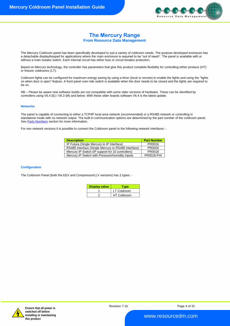
The Mercury Range From Resource Data Management
The Mercury Coldroom panel has been specifically developed to suit a variety of coldroom needs. The purpose developed enclosure has a detachable display/keypad for applications where the main enclosure is required to be “out of reach”. The panel is available with or without a main isolator switch. Each internal circuit has either fuse or circuit breaker protection. Based on Mercury technology, the controller has parameters that give this product complete flexibility for controlling either produce (HT) or freezer coldrooms (LT). Coldroom lights can be configured for maximum energy saving by using a timer (local or remote) to enable the lights and using the “lights on when door is open” feature. A front panel over-ride switch is available when the door needs to be closed and the lights are required to be on. NB – Please be aware new software builds are not compatible with some older versions of hardware. These can be identified by controllers using V6.4 (E) / V6.3 (M) and below. With these older boards software V6.4 is the latest update. Networks
The panel is capable of connecting to either a TCP/IP local area network (recommended) or a RS485 network or controlling in standalone mode with no network output. The built-in communication options are determined by the part number of the coldroom panel. See Parts Numbers section for more information. For non network versions it is possible to connect the Coldroom panel to the following network interfaces: -
Description Part Number
IP Futura (Single Mercury to IP Interface) PR0016
RS485 Interface (Single Mercury to RS485 Interface) PR0026
Mercury IP Switch (IP support for 10 controllers) PR0018
Mercury IP Switch with Pressure/Humidity Inputs PR0018-PHI
Configuration
The Coldroom Panel (both the EEV and Compressor/LLV versions) has 2 types: -
Display value Type
1 LT Coldroom
2 HT Coldroom
Revision 7.1b Page 5 of 31
Mercury Coldroom Panel Installation Guide
www.resourcedm.com
Warning
Please Note The specifications of the product detailed on this Set-Up Guide may change without notice. RDM Ltd. shall not be liable for errors or for incidental or consequential damages, directly and indirectly, in connection with the furnishing, performance or misuse of this product or document.
Ensure that all power is switched off before installing or maintaining this product
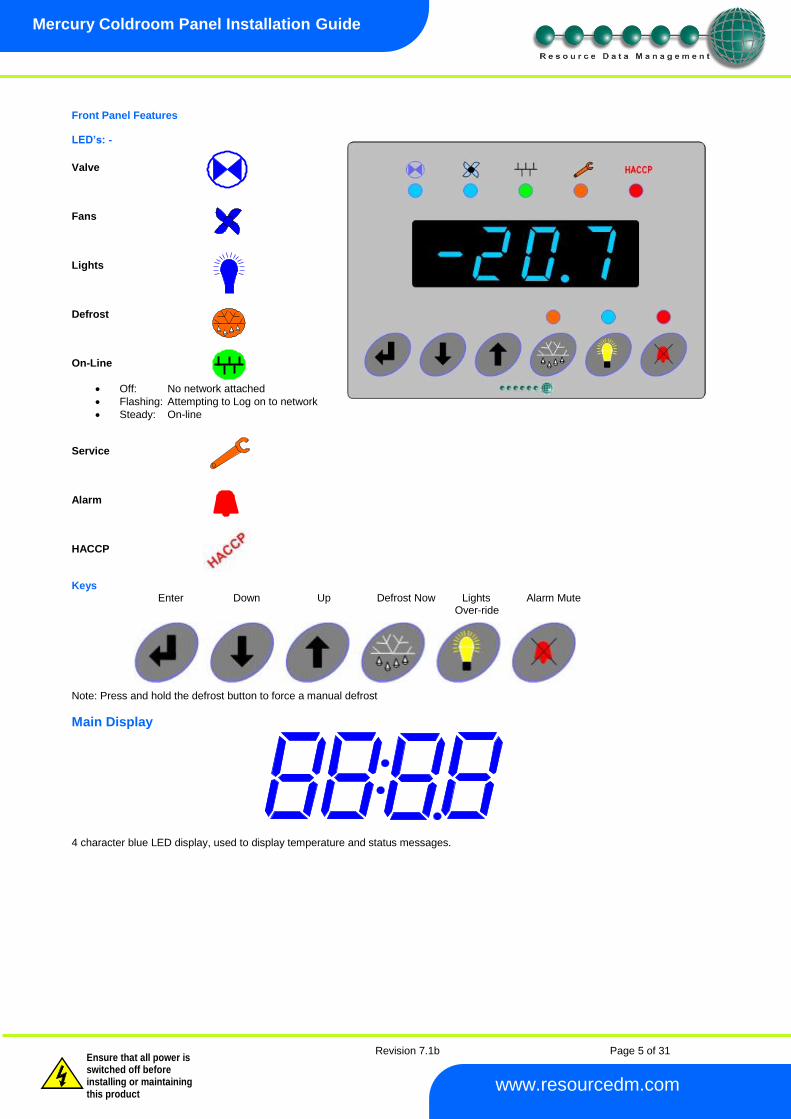
Front Panel Features LED’s: -
Valve Fans Lights Defrost On-Line
Off: No network attached
Flashing: Attempting to Log on to network
Steady: On-line Service Alarm HACCP Keys Enter Down Up Defrost Now Lights Alarm Mute Over-ride Note: Press and hold the defrost button to force a manual defrost
Main Display 4 character blue LED display, used to display temperature and status messages.
Revision 7.1b Page 6 of 31
Mercury Coldroom Panel Installation Guide
www.resourcedm.com
Warning
Please Note The specifications of the product detailed on this Set-Up Guide may change without notice. RDM Ltd. shall not be liable for errors or for incidental or consequential damages, directly and indirectly, in connection with the furnishing, performance or misuse of this product or document.
Ensure that all power is switched off before installing or maintaining this product
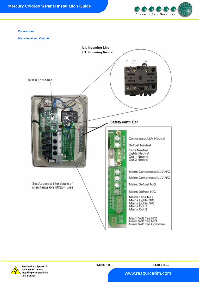
Connections
Mains Input and Outputs
Revision 7.1b Page 7 of 31
Mercury Coldroom Panel Installation Guide
www.resourcedm.com
Warning
Please Note The specifications of the product detailed on this Set-Up Guide may change without notice. RDM Ltd. shall not be liable for errors or for incidental or consequential damages, directly and indirectly, in connection with the furnishing, performance or misuse of this product or document.
Ensure that all power is switched off before installing or maintaining this product
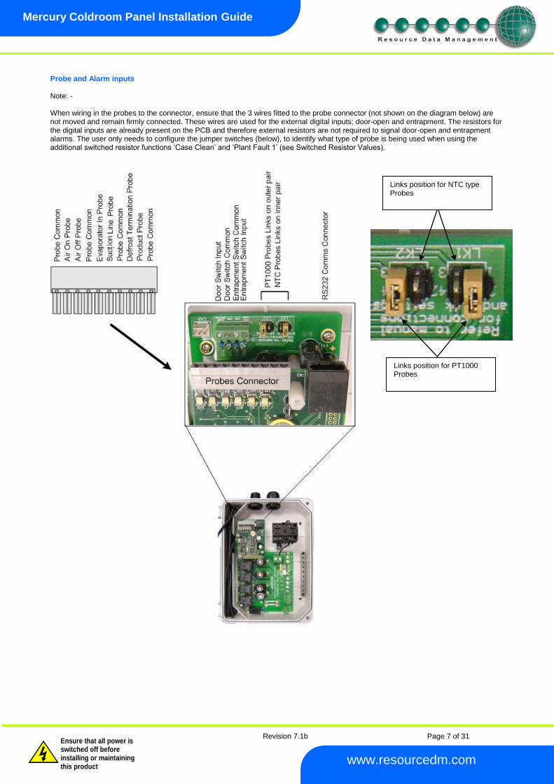
Probe and Alarm inputs Note: - When wiring in the probes to the connector, ensure that the 3 wires fitted to the probe connector (not shown on the diagram below) are not moved and remain firmly connected. These wires are used for the external digital inputs; door-open and entrapment. The resistors for the digital inputs are already present on the PCB and therefore external resistors are not required to signal door-open and entrapment alarms. The user only needs to configure the jumper switches (below), to identify what type of probe is being used when using the additional switched resistor functions ‘Case Clean’ and ‘Plant Fault 1’ (see Switched Resistor Values).
Links position for PT1000 Probes
Links position for NTC type Probes
Revision 7.1b Page 8 of 31
Mercury Coldroom Panel Installation Guide
www.resourcedm.com
Warning
Please Note The specifications of the product detailed on this Set-Up Guide may change without notice. RDM Ltd. shall not be liable for errors or for incidental or consequential damages, directly and indirectly, in connection with the furnishing, performance or misuse of this product or document.
Ensure that all power is switched off before installing or maintaining this product
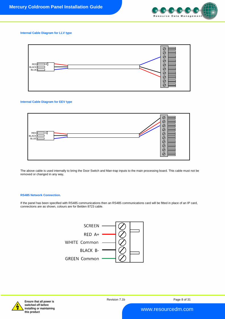
Internal Cable Diagram for LLV type
Internal Cable Diagram for EEV type
The above cable is used internally to bring the Door Switch and Man-trap inputs to the main processing board. This cable must not be removed or changed in any way, RS485 Network Connection.
If the panel has been specified with RS485 communications then an RS485 communications card will be fitted in place of an IP card, connections are as shown, colours are for Belden 8723 cable.
RED
BLACK
BLUE
RED
BLACK
BLUE
Revision 7.1b Page 9 of 31
Mercury Coldroom Panel Installation Guide
www.resourcedm.com
Warning
Please Note The specifications of the product detailed on this Set-Up Guide may change without notice. RDM Ltd. shall not be liable for errors or for incidental or consequential damages, directly and indirectly, in connection with the furnishing, performance or misuse of this product or document.
Ensure that all power is switched off before installing or maintaining this product
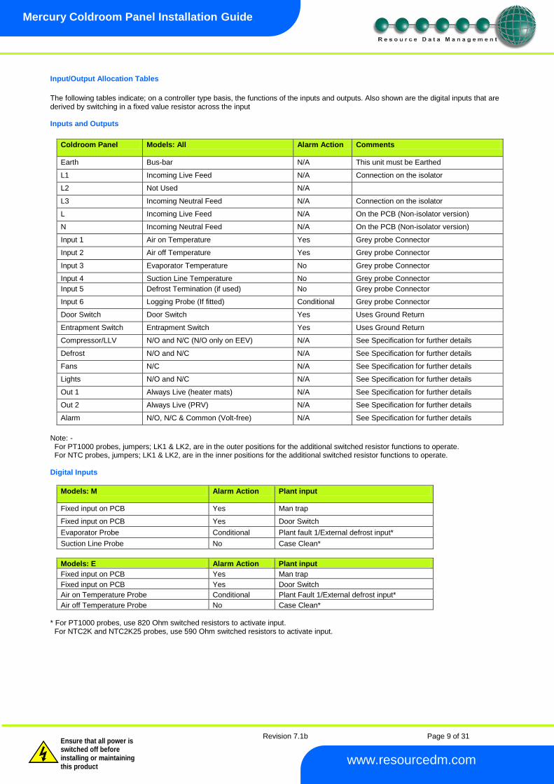
Input/Output Allocation Tables
The following tables indicate; on a controller type basis, the functions of the inputs and outputs. Also shown are the digital inputs that are derived by switching in a fixed value resistor across the input Inputs and Outputs
Coldroom Panel Models: All Alarm Action Comments
Earth Bus-bar N/A This unit must be Earthed
L1 Incoming Live Feed N/A Connection on the isolator
L2 Not Used N/A
L3 Incoming Neutral Feed N/A Connection on the isolator
L Incoming Live Feed N/A On the PCB (Non-isolator version)
N Incoming Neutral Feed N/A On the PCB (Non-isolator version)
Input 1 Air on Temperature Yes Grey probe Connector
Input 2 Air off Temperature Yes Grey probe Connector
Input 3 Evaporator Temperature No Grey probe Connector
Input 4 Suction Line Temperature No Grey probe Connector
Input 5 Defrost Termination (if used) No Grey probe Connector
Input 6 Logging Probe (If fitted) Conditional Grey probe Connector
Door Switch Door Switch Yes Uses Ground Return
Entrapment Switch Entrapment Switch Yes Uses Ground Return
Compressor/LLV N/O and N/C (N/O only on EEV) N/A See Specification for further details
Defrost N/O and N/C N/A See Specification for further details
Fans N/C N/A See Specification for further details
Lights N/O and N/C N/A See Specification for further details
Out 1 Always Live (heater mats) N/A See Specification for further details
Out 2 Always Live (PRV) N/A See Specification for further details
Alarm N/O, N/C & Common (Volt-free) N/A See Specification for further details
Note: - For PT1000 probes, jumpers; LK1 & LK2, are in the outer positions for the additional switched resistor functions to operate. For NTC probes, jumpers; LK1 & LK2, are in the inner positions for the additional switched resistor functions to operate. Digital Inputs
Models: M Alarm Action Plant input
Fixed input on PCB Yes Man trap
Fixed input on PCB Yes Door Switch
Evaporator Probe Conditional Plant fault 1/External defrost input*
Suction Line Probe No Case Clean*
Models: E Alarm Action Plant input
Fixed input on PCB Yes Man trap
Fixed input on PCB Yes Door Switch
Air on Temperature Probe Conditional Plant Fault 1/External defrost input*
Air off Temperature Probe No Case Clean*
* For PT1000 probes, use 820 Ohm switched resistors to activate input. For NTC2K and NTC2K25 probes, use 590 Ohm switched resistors to activate input.
Revision 7.1b Page 10 of 31
Mercury Coldroom Panel Installation Guide
www.resourcedm.com
Warning
Please Note The specifications of the product detailed on this Set-Up Guide may change without notice. RDM Ltd. shall not be liable for errors or for incidental or consequential damages, directly and indirectly, in connection with the furnishing, performance or misuse of this product or document.
Ensure that all power is switched off before installing or maintaining this product
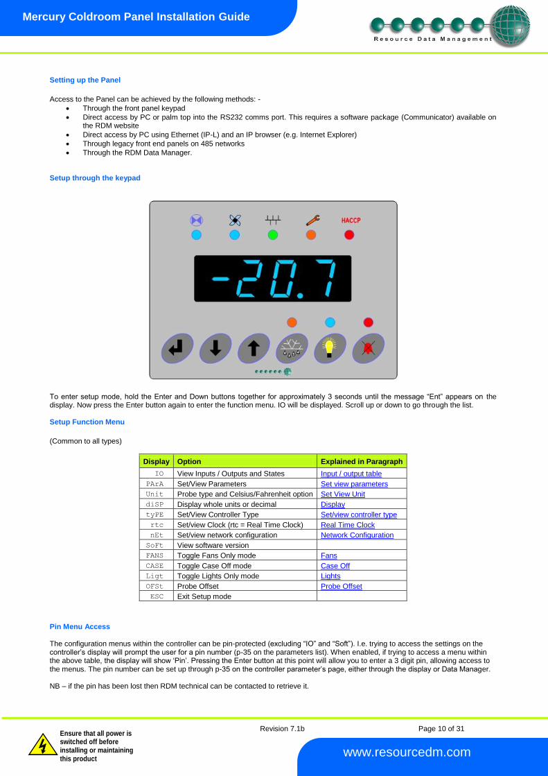
Setting up the Panel
Access to the Panel can be achieved by the following methods: -
Through the front panel keypad
Direct access by PC or palm top into the RS232 comms port. This requires a software package (Communicator) available on the RDM website
Direct access by PC using Ethernet (IP-L) and an IP browser (e.g. Internet Explorer)
Through legacy front end panels on 485 networks
Through the RDM Data Manager. Setup through the keypad
To enter setup mode, hold the Enter and Down buttons together for approximately 3 seconds until the message “Ent” appears on the display. Now press the Enter button again to enter the function menu. IO will be displayed. Scroll up or down to go through the list. Setup Function Menu
(Common to all types)
Display Option Explained in Paragraph
IO View Inputs / Outputs and States Input / output table
PArA Set/View Parameters Set view parameters
Unit Probe type and Celsius/Fahrenheit option Set View Unit
diSP Display whole units or decimal Display
tyPE Set/View Controller Type Set/view controller type
rtc Set/view Clock (rtc = Real Time Clock) Real Time Clock
nEt Set/view network configuration Network Configuration
SoFt View software version
FANS Toggle Fans Only mode Fans
CASE Toggle Case Off mode Case Off
Ligt Toggle Lights Only mode Lights
OFSt Probe Offset Probe Offset
ESC Exit Setup mode
Pin Menu Access The configuration menus within the controller can be pin-protected (excluding “IO” and “Soft”). I.e. trying to access the settings on the controller’s display will prompt the user for a pin number (p-35 on the parameters list). When enabled, if trying to access a menu within the above table, the display will show ‘Pin’. Pressing the Enter button at this point will allow you to enter a 3 digit pin, allowing access to the menus. The pin number can be set up through p-35 on the controller parameter’s page, either through the display or Data Manager. NB – if the pin has been lost then RDM technical can be contacted to retrieve it.

Revision 7.1b Page 11 of 31
Mercury Coldroom Panel Installation Guide
www.resourcedm.com
Warning
Please Note The specifications of the product detailed on this Set-Up Guide may change without notice. RDM Ltd. shall not be liable for errors or for incidental or consequential damages, directly and indirectly, in connection with the furnishing, performance or misuse of this product or document.
Ensure that all power is switched off before installing or maintaining this product
Recommended set-up method If you are not connecting to a network and want to set up the controller through the buttons we recommend you use the following order from the function menu.
rtc. Real time clock (This will automatically synchronise on network systems)
a. Use the up or down buttons to scroll through the display until the display reads “rtc” b. Press enter. The display will show “t-1”. press enter again c. Scroll hours up or down (0 – 23) press enter d. Use up button to select “t-2”, press enter e. Scroll minutes up or down (0 – 59) press enter f. Repeat for t-3 (seconds 0 – 59) g. Repeat for t -4 (Days up to 31) h. Repeat for t -5 (months up to 12) i. Repeat for t -6 (Year up to 99) j. Use up button to display “ESC”, press enter to display “rtc”
Time clock is now set
type. Set/view controller type
a. From the function menu scroll to select type, press enter b. Use the up/down buttons to scroll through case/coldroom configuration types. (see configuration table on page 3) c. Press enter. d. Scroll to select “ESC” e. Press enter
Controller type configuration is now set
Unit. Set/view temperature unit and Probe type From the function menu scroll to select Unit Press enter and the value will be displayed: -
Probe Types
0 for PT1000 Celsius
1 for PT1000 Fahrenheit 2 for NTC2K Celsius 3 for NTC2K Fahrenheit
4 for 470R Celsius 5 for 470R Fahrenheit 6 for 700R Celsius 7 for 700R Fahrenheit 8 for 3K Celsius 9 for 3K Fahrenheit
Range of probes -49.0 degrees to +60.0 Degrees (PT1000 - 60.0 to 128.0 Degrees C) Note: If probe is used with switched resistor range at low end is only -42.0 degrees Note: Temperature range for NTC2K25 is restricted to -42
oC to +60
oC
for probe inputs with a secondary function (switched
resistors) and -49 o
C to +60 o
C for inputs that have no secondary function.
Use the up or down keys to select the units and press enter. This function is now complete Display
From the function menu scroll to and select diSP. Press enter and one of the following values will be shown: - 0. Controller display will show the whole number and tenths value of a temperature reading. (Default) 1. Controller display will show temperatures as a whole number.
10 for NTC2K25 Celsius 11 for NTC2K25 Fahrenheit 12 for 5K Celsius 13 for 5K Fahrenheit 14 for 6K Celsius 15 for 6K Fahrenheit 16 for NTC10K Celsius 17 for NTC10K Fahrenheit 18 for NTC10K(2) Celsius (USA NTC10K) 19 for NTC10K(2) Fahrenheit (USA NTC10K)
Revision 7.1b Page 12 of 31
Mercury Coldroom Panel Installation Guide
www.resourcedm.com
Warning
Please Note The specifications of the product detailed on this Set-Up Guide may change without notice. RDM Ltd. shall not be liable for errors or for incidental or consequential damages, directly and indirectly, in connection with the furnishing, performance or misuse of this product or document.
Ensure that all power is switched off before installing or maintaining this product
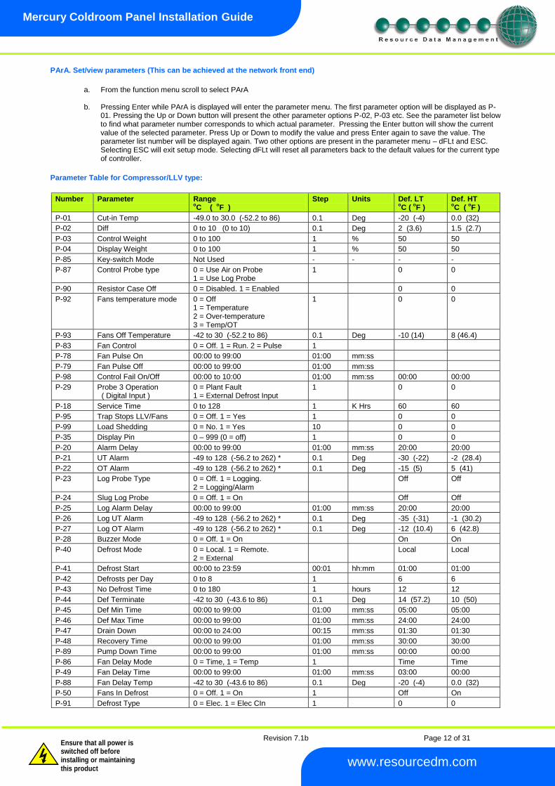
PArA. Set/view parameters (This can be achieved at the network front end)
a. From the function menu scroll to select PArA
b. Pressing Enter while PArA is displayed will enter the parameter menu. The first parameter option will be displayed as P-
01. Pressing the Up or Down button will present the other parameter options P-02, P-03 etc. See the parameter list below to find what parameter number corresponds to which actual parameter. Pressing the Enter button will show the current value of the selected parameter. Press Up or Down to modify the value and press Enter again to save the value. The parameter list number will be displayed again. Two other options are present in the parameter menu – dFLt and ESC. Selecting ESC will exit setup mode. Selecting dFLt will reset all parameters back to the default values for the current type of controller.
Parameter Table for Compressor/LLV type:
Number Parameter Range
oC (
oF )
Step Units Def. LT oC (
oF )
Def. HT oC (
oF )
P-01 Cut-in Temp -49.0 to 30.0 (-52.2 to 86) 0.1 Deg -20 (-4) 0.0 (32)
P-02 Diff 0 to 10 (0 to 10) 0.1 Deg 2 (3.6) 1.5 (2.7)
P-03 Control Weight 0 to 100 1 % 50 50
P-04 Display Weight 0 to 100 1 % 50 50
P-85 Key-switch Mode Not Used - - - -
P-87 Control Probe type 0 = Use Air on Probe 1 = Use Log Probe
1 0 0
P-90 Resistor Case Off 0 = Disabled. 1 = Enabled 0 0
P-92 Fans temperature mode 0 = Off 1 = Temperature 2 = Over-temperature 3 = Temp/OT
1 0 0
P-93 Fans Off Temperature -42 to 30 (-52.2 to 86) 0.1 Deg -10 (14) 8 (46.4)
P-83 Fan Control 0 = Off. 1 = Run. 2 = Pulse 1
P-78 Fan Pulse On 00:00 to 99:00 01:00 mm:ss
P-79 Fan Pulse Off 00:00 to 99:00 01:00 mm:ss
P-98 Control Fail On/Off 00:00 to 10:00 01:00 mm:ss 00:00 00:00
P-29 Probe 3 Operation ( Digital Input )
0 = Plant Fault 1 = External Defrost Input
1 0 0
P-18 Service Time 0 to 128 1 K Hrs 60 60
P-95 Trap Stops LLV/Fans 0 = Off. 1 = Yes 1 0 0
P-99 Load Shedding 0 = No. 1 = Yes 10 0 0
P-35 Display Pin 0 – 999 (0 = off) 1 0 0
P-20 Alarm Delay 00:00 to 99:00 01:00 mm:ss 20:00 20:00
P-21 UT Alarm -49 to 128 (-56.2 to 262) * 0.1 Deg -30 (-22) -2 (28.4)
P-22 OT Alarm -49 to 128 (-56.2 to 262) * 0.1 Deg -15 (5) 5 (41)
P-23 Log Probe Type 0 = Off. 1 = Logging. 2 = Logging/Alarm
Off Off
P-24 Slug Log Probe 0 = Off. 1 = On Off Off
P-25 Log Alarm Delay 00:00 to 99:00 01:00 mm:ss 20:00 20:00
P-26 Log UT Alarm -49 to 128 (-56.2 to 262) * 0.1 Deg -35 (-31) -1 (30.2)
P-27 Log OT Alarm -49 to 128 (-56.2 to 262) * 0.1 Deg -12 (10.4) 6 (42.8)
P-28 Buzzer Mode 0 = Off. 1 = On On On
P-40 Defrost Mode 0 = Local. 1 = Remote. 2 = External
Local Local
P-41 Defrost Start 00:00 to 23:59 00:01 hh:mm 01:00 01:00
P-42 Defrosts per Day 0 to 8 1 6 6
P-43 No Defrost Time 0 to 180 1 hours 12 12
P-44 Def Terminate -42 to 30 (-43.6 to 86) 0.1 Deg 14 (57.2) 10 (50)
P-45 Def Min Time 00:00 to 99:00 01:00 mm:ss 05:00 05:00
P-46 Def Max Time 00:00 to 99:00 01:00 mm:ss 24:00 24:00
P-47 Drain Down 00:00 to 24:00 00:15 mm:ss 01:30 01:30
P-48 Recovery Time 00:00 to 99:00 01:00 mm:ss 30:00 30:00
P-89 Pump Down Time 00:00 to 99:00 01:00 mm:ss 00:00 00:00
P-86 Fan Delay Mode 0 = Time, 1 = Temp 1 Time Time
P-49 Fan Delay Time 00:00 to 99:00 01:00 mm:ss 03:00 00:00
P-88 Fan Delay Temp -42 to 30 (-43.6 to 86) 0.1 Deg -20 (-4) 0.0 (32)
P-50 Fans In Defrost 0 = Off. 1 = On 1 Off On
P-91 Defrost Type 0 = Elec. 1 = Elec CIn 1 0 0
Revision 7.1b Page 13 of 31
Mercury Coldroom Panel Installation Guide
www.resourcedm.com
Warning
Please Note The specifications of the product detailed on this Set-Up Guide may change without notice. RDM Ltd. shall not be liable for errors or for incidental or consequential damages, directly and indirectly, in connection with the furnishing, performance or misuse of this product or document.
Ensure that all power is switched off before installing or maintaining this product
P-94 Defrost Hold 0 = Off. 1 = On 1 0 0
P-96 Defrost Skip 0 = Off. 1 = On 1 0 0
P-97 Defrost Skip Time 00:00 to 99:00 01:00 mm:ss 12:00 12:00
P-80 Door alarm dly 00:00 to 99:00 01:00 mm:ss 20:00 20:00
P-81 Door Closes LL 0 = No. 1 = Yes 1 No No
P-82 Door Stops Fan 0 = No. 1 = Yes 1 No No
P-60 Lights Mode 0 = Local. 1 = Remote 1 Local Local
P-61 Sun Lights On 00:00 to 23:59 00:01 hh:mm 08:00 08:00
P-62 Sun Lights Off 00:00 to 23:59 00:01 hh:mm 20:00 20:00
P-63 Mon Lights On 00:00 to 23:59 00:01 hh:mm 08:00 08:00
P-64 Mon Lights Off 00:00 to 23:59 00:01 hh:mm 20:00 20:00
P-65 Tue Lights On 00:00 to 23:59 00:01 hh:mm 08:00 08:00
P-66 Tue Lights Off 00:00 to 23:59 00:01 hh:mm 20:00 20:00
P-67 Wed Lights On 00:00 to 23:59 00:01 hh:mm 08:00 08:00
P-68 Wed Lights Off 00:00 to 23:59 00:01 hh:mm 20:00 20:00
P-69 Thu Lights On 00:00 to 23:59 00:01 hh:mm 08:00 08:00
P-70 Thu Lights Off 00:00 to 23:59 00:01 hh:mm 20:00 20:00
P-71 Fri Lights On 00:00 to 23:59 00:01 hh:mm 08:00 08:00
P-72 Fri Lights Off 00:00 to 23:59 00:01 hh:mm 20:00 20:00
P-73 Sat Lights On 00:00 to 23:59 00:01 hh:mm 08:00 08:00
P-74 Sat Lights Off 00:00 to 23:59 00:01 hh:mm 20:00 20:00
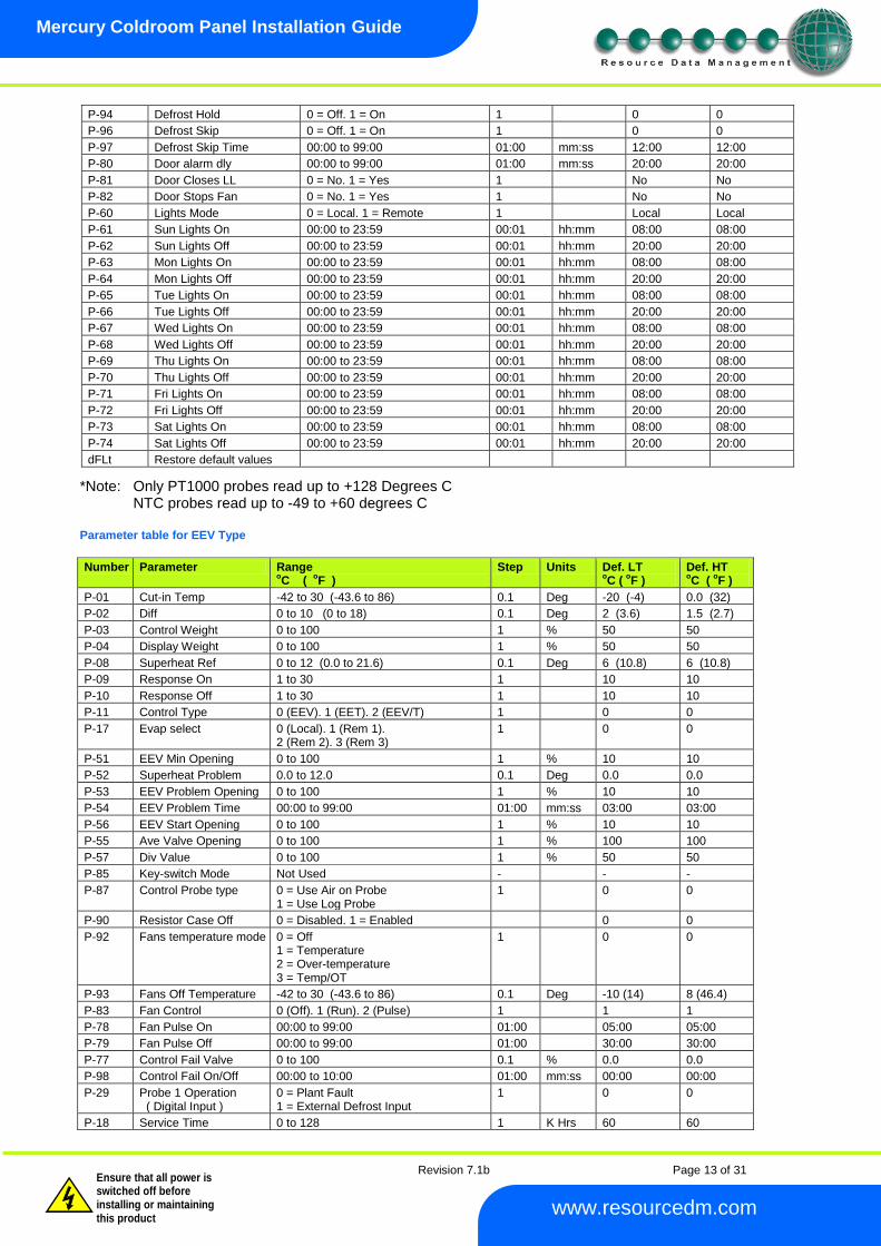
dFLt Restore default values
*Note: Only PT1000 probes read up to +128 Degrees C NTC probes read up to -49 to +60 degrees C
Parameter table for EEV Type
Number Parameter Range oC (
oF )
Step Units Def. LT oC (
oF )
Def. HT oC (
oF )
P-01 Cut-in Temp -42 to 30 (-43.6 to 86) 0.1 Deg -20 (-4) 0.0 (32)
P-02 Diff 0 to 10 (0 to 18) 0.1 Deg 2 (3.6) 1.5 (2.7)
P-03 Control Weight 0 to 100 1 % 50 50
P-04 Display Weight 0 to 100 1 % 50 50
P-08 Superheat Ref 0 to 12 (0.0 to 21.6) 0.1 Deg 6 (10.8) 6 (10.8)
P-09 Response On 1 to 30 1 10 10
P-10 Response Off 1 to 30 1 10 10
P-11 Control Type 0 (EEV). 1 (EET). 2 (EEV/T) 1 0 0
P-17 Evap select 0 (Local). 1 (Rem 1). 2 (Rem 2). 3 (Rem 3)
1 0 0
P-51 EEV Min Opening 0 to 100 1 % 10 10
P-52 Superheat Problem 0.0 to 12.0 0.1 Deg 0.0 0.0
P-53 EEV Problem Opening 0 to 100 1 % 10 10
P-54 EEV Problem Time 00:00 to 99:00 01:00 mm:ss 03:00 03:00
P-56 EEV Start Opening 0 to 100 1 % 10 10
P-55 Ave Valve Opening 0 to 100 1 % 100 100
P-57 Div Value 0 to 100 1 % 50 50
P-85 Key-switch Mode Not Used - - -
P-87 Control Probe type 0 = Use Air on Probe 1 = Use Log Probe
1 0 0
P-90 Resistor Case Off 0 = Disabled. 1 = Enabled 0 0
P-92 Fans temperature mode 0 = Off 1 = Temperature 2 = Over-temperature 3 = Temp/OT
1 0 0
P-93 Fans Off Temperature -42 to 30 (-43.6 to 86) 0.1 Deg -10 (14) 8 (46.4)
P-83 Fan Control 0 (Off). 1 (Run). 2 (Pulse) 1 1 1
P-78 Fan Pulse On 00:00 to 99:00 01:00 05:00 05:00
P-79 Fan Pulse Off 00:00 to 99:00 01:00 30:00 30:00
P-77 Control Fail Valve 0 to 100 0.1 % 0.0 0.0
P-98 Control Fail On/Off 00:00 to 10:00 01:00 mm:ss 00:00 00:00
P-29 Probe 1 Operation ( Digital Input )
0 = Plant Fault 1 = External Defrost Input
1 0 0
P-18 Service Time 0 to 128 1 K Hrs 60 60
Revision 7.1b Page 14 of 31
Mercury Coldroom Panel Installation Guide
www.resourcedm.com
Warning
Please Note The specifications of the product detailed on this Set-Up Guide may change without notice. RDM Ltd. shall not be liable for errors or for incidental or consequential damages, directly and indirectly, in connection with the furnishing, performance or misuse of this product or document.
Ensure that all power is switched off before installing or maintaining this product
P-95 Trap Stops LLV/Fans 0 (No). 1 (Yes0 1 0 0
P-99 Load Shedding 0 (Off). 1 (Mode 10. 2 (Mode 2) 1 0 0
P-35 Display Pin 0 – 999 (0 = off) 1 0 0
P-20 Alarm Delay 00:00 to 99:00 01:00 mm:ss 20:00 20:00
P-21 UT Alarm -49 to 60 (-56.2 to 140) 0.1 Deg -30 (-22) -2 (28.4)
P-22 OT Alarm -49 to 60 (-56.2 to 140) 0.1 Deg -15 (5) 5 (41)
P-23 Log Probe Type 0 = Off. (Logging with no alarms) 1 = Logging (Probe Fault alarm only) 2 = Logging/Alarm (Prb Flt and OT/UT)
Off Off
P-24 Slug Log Probe 0 = Off. 1 = On Off Off
P-25 Log Alarm Delay 00:00 to 99:00 01:00 mm:ss 20:00 20:00
P-26 Log UT Alarm -49 to 60 (-56.2 to 140) 0.1 Deg -35 (-31) -1 (30.2)
P-27 Log OT Alarm -49 to 60 (-56.2 to 140) 0.1 Deg -12 (10.4) 6 (42.8)
P-28 Buzzer Mode 0 = Off. 1 = On On On
P-40 Defrost Mode 0 (Local), 1 (Remote), 2 (External)
Local Local
P-41 Defrost Start 00:00 to 23:59 00:01 hh:mm 01:00 01:00
P-42 Defrosts per Day 0 to 8 1 6 6
P-43 No Defrost Time 0 to 25 1 hours 12 12
P-44 Def Terminate -42 to 30 (-43.6 to 86) 0.1 Deg 14 (57.2) 10 (50)
P-45 Def Min Time 00:00 to 99:00 01:00 mm:ss 05:00 05:00
P-46 Def Max Time 00:00 to 99:00 01:00 mm:ss 24:00 24:00
P-47 Drain Down 00:00 to 24:00 00:15 mm:ss 01:30 01:30
P-48 Recovery Time 00:00 to 99:00 01:00 mm:ss 30:00 30:00
P-89 Pump Down Time 00:00 to 99:00 01:00 mm:ss 00:00 00:00
P-86 Fan Delay mode 0 = Time 1 = Temp
1 0 0
P-49 Fan delay 00:00 to 99:00 01:00 mm:ss 03:00 03:00
P-88 Fan Delay Temp -42 to 30 (-43.6 to 86) 0.1 Deg -20 (-4) 0.0 (32)
P-50 Fans In Defrost 0 = Off. 1 = On On On
P-91 Defrost Type 0 (Elec). 1 (Elec/Cin) 1 0 0
P-94 Defrost Hold 0 = Off. 1 = On Off Off
P-86 Defrost Skip 0 (Off). 1(On) 1 0 0
P-97 Defrost Skip Time 00:00 to 99:00 01:00 mm:ss 12:00 12:00
P-80 Door alarm delay 00:00 to 99:00 01:00 mm:ss 20:00 20:00
P-81 Door Closes EEV 0 = No. 1 = Yes No No
P-82 Door Stops Fan 0 = No. 1 = Yes No No
P-60 Lights Mode 0 (Local), 1 (Remote) Local Local
P-61 Sun Lights On 00:00 to 23:59 00:01 hh:mm 08:00 08:00
P-62 Sun Lights Off 00:00 to 23:59 00:01 hh:mm 20:00 20:00
P-63 Mon Lights On 00:00 to 23:59 00:01 hh:mm 08:00 08:00
P-64 Mon Lights Off 00:00 to 23:59 00:01 hh:mm 20:00 20:00
P-65 Tue Lights On 00:00 to 23:59 00:01 hh:mm 08:00 08:00
P-66 Tue Lights Off 00:00 to 23:59 00:01 hh:mm 20:00 20:00
P-67 Wed Lights On 00:00 to 23:59 00:01 hh:mm 08:00 08:00
P-68 Wed Lights Off 00:00 to 23:59 00:01 hh:mm 20:00 20:00
P-69 Thu Lights On 00:00 to 23:59 00:01 hh:mm 08:00 08:00
P-70 Thu Lights Off 00:00 to 23:59 00:01 hh:mm 20:00 20:00
P-71 Fri Lights On 00:00 to 23:59 00:01 hh:mm 08:00 08:00
P-72 Fri Lights Off 00:00 to 23:59 00:01 hh:mm 20:00 20:00
P-73 Sat Lights On 00:00 to 23:59 00:01 hh:mm 08:00 08:00
P-74 Sat Lights Off 00:00 to 23:59 00:01 hh:mm 20:00 20:00
P-30 Broadcast ID 0 to 999 1 0 0
P-31 Refrigerant See Refrigerant Table Below 1 0 0
P-32 Pressure Units 0 (Absolute). 1 (Gauge) 1 1 1
P-33 Evap Offset 0.0 to 1,0 0.1 0.0 0.0
P-34 Glide 0.0 to 5.0 0.1 0.0 0.0
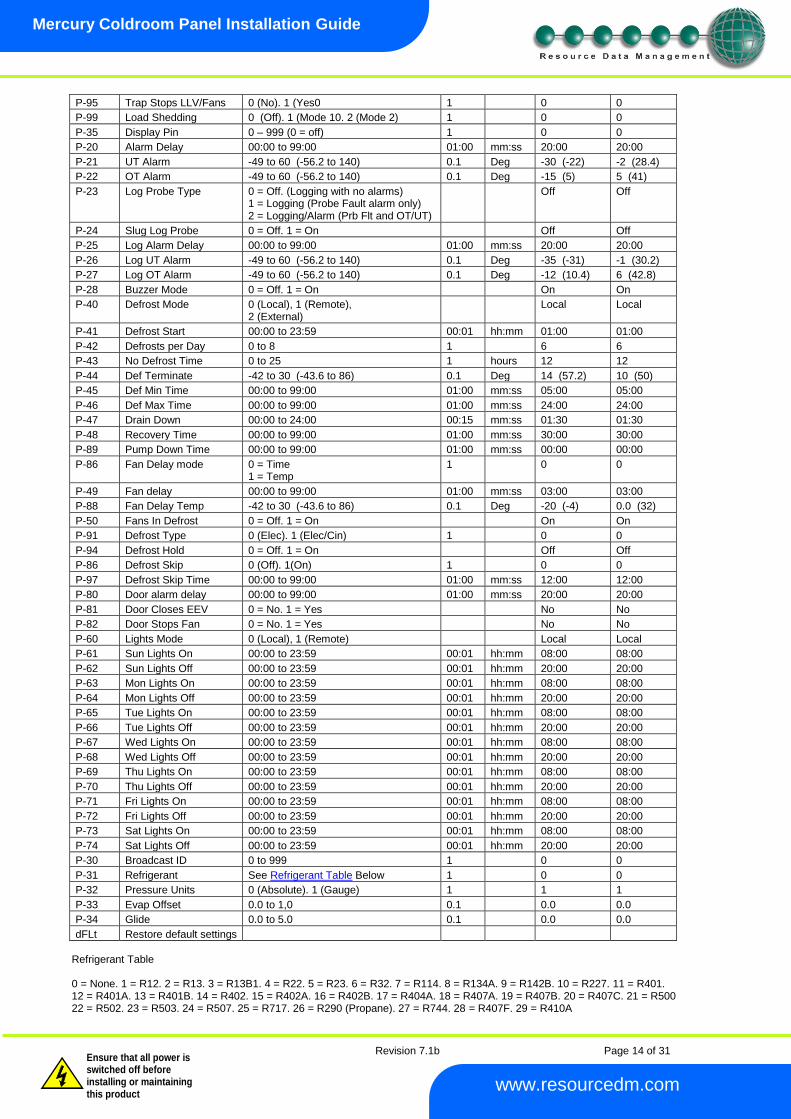
dFLt Restore default settings
Refrigerant Table 0 = None. 1 = R12. 2 = R13. 3 = R13B1. 4 = R22. 5 = R23. 6 = R32. 7 = R114. 8 = R134A. 9 = R142B. 10 = R227. 11 = R401. 12 = R401A. 13 = R401B. 14 = R402. 15 = R402A. 16 = R402B. 17 = R404A. 18 = R407A. 19 = R407B. 20 = R407C. 21 = R500 22 = R502. 23 = R503. 24 = R507. 25 = R717. 26 = R290 (Propane). 27 = R744. 28 = R407F. 29 = R410A
Revision 7.1b Page 15 of 31
Mercury Coldroom Panel Installation Guide
www.resourcedm.com
Warning
Please Note The specifications of the product detailed on this Set-Up Guide may change without notice. RDM Ltd. shall not be liable for errors or for incidental or consequential damages, directly and indirectly, in connection with the furnishing, performance or misuse of this product or document.
Ensure that all power is switched off before installing or maintaining this product
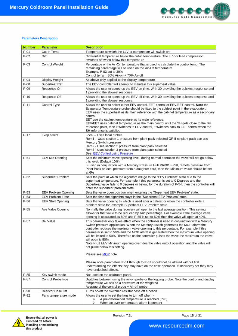
Parameters Description
Number Parameter Description
P-01 Cut-in Temp Temperature at which the LLV or compressor will switch on
P-02 Diff Differential temperature below the cut-in temperature. The LLV or lead compressor switches off when below this temperature
P-03 Control Weight Percentage of the Air-On temperature that is used to calculate the control temp. The remaining percentage will be used on the Air-Off temperature Example, P-03 set to 30% Control temp = 30% Air-on + 70% Air-off
P-04 Display Weight As above only applied to the display temperature
P-08 Superheat Ref The EEV controller will attempt to maintain this superheat value
P-09 Response On Allows the user to speed up the EEV on time. With 30 providing the quickest response and 1 providing the slowest response.
P-10 Response Off Allows the user to speed up the EEV off time. With 30 providing the quickest response and 1 providing the slowest response.
P-11 Control Type Allows the user to select either EEV control, EET control or EEV/EET control. Note the Evaporator Temperature probe should be fitted to the coldest point in the evaporator. EEV uses the superheat as its main reference with the cabinet temperature as a secondary control. EET use the cabinet temperature as its main reference. EEV/EET uses cabinet temperature as the main control until the SH gets close to the SH reference point, then it switches to EEV control, it switches back to EET control when the SH reference is satisfied.
P-17 Evap select Local – Uses local probes Rem1 – Uses section 1 pressure from plant pack selected OR If no plant pack can use Mercury Switch pressure Rem2 - Uses section 2 pressure from plant pack selected Rem3 - Uses section 3 pressure from plant pack selected See: EEV Control using Pressure
P-51 EEV Min Opening Sets the minimum valve opening level, during normal operation the valve will not go below this level. (Default 10%) IF used in conjunction with a Mercury Pressure Hub PR0018-PHI, remote pressure from Plant Pack or local pressure from a daughter card, then the Minimum value should be set at 0%
P-52 Superheat Problem Sets the point at which the algorithm will go to the “EEV Problem” state due to the superheat temperature. For example if this parameter is set to 0 Degrees and the Superheat value falls to 0 degrees or below, for the duration of P-54, then the controller will enter the superheat problem state.
P-53 EEV Problem Opening Sets the valve open position when entering the “Superheat EEV Problem” state.
P-54 EEV Problem Time Sets the time the algorithm stays in the “Superheat EEV Problem” state.
P-56 EEV Start Opening Sets the valve opening % which is used after a defrost or when the controller exits a problem state for, example Superheat EEV Problem state
P-55 Ave Valve Opening Normally the valve during recovery will open to the last average position. This setting allows for that value to be reduced by said percentage. For example if the average valve opening is calculated as 80% and P-55 is set to 50% then the valve will open at 40%.
P-57 Div Value This parameter only takes effect when the controller is used in conjunction with a Mercury Switch pressure application. When the Mercury Switch generates the MOP alarm the controller reduces the maximum valve opening to this percentage. For example if this parameter is set to 50% and the MOP alarm is generated then the maximum valve opening will be limited to 50%. Therefore as the controller pulses the valve the maximum the valve will open is 50%. Note P-51 EEV Minimum opening overrides the valve output operation and the valve will not pulse below this setting. Please see MOP note.
Please note parameters P-51 through to P-57 should not be altered without first understanding the effects they may have on the case operation. If incorrectly set they may have undesired affects.
P-85 Key switch mode Not used on the coldroom panel.
P-87 Control Probe type Switches between using the air-on probe or the logging probe. Note the control and display temperature will still be a derivative of the weighted Average of the control probe + Air-off probe
P-90 Resistor Case Off Turns on/off the switched resistor case off function
P-92 Fans temperature mode Allows the user to set the fans to turn off when: - A pre-determined temperature is reached (P93) When an over-temperature alarm is present
Revision 7.1b Page 16 of 31
Mercury Coldroom Panel Installation Guide
www.resourcedm.com
Warning
Please Note The specifications of the product detailed on this Set-Up Guide may change without notice. RDM Ltd. shall not be liable for errors or for incidental or consequential damages, directly and indirectly, in connection with the furnishing, performance or misuse of this product or document.
Ensure that all power is switched off before installing or maintaining this product
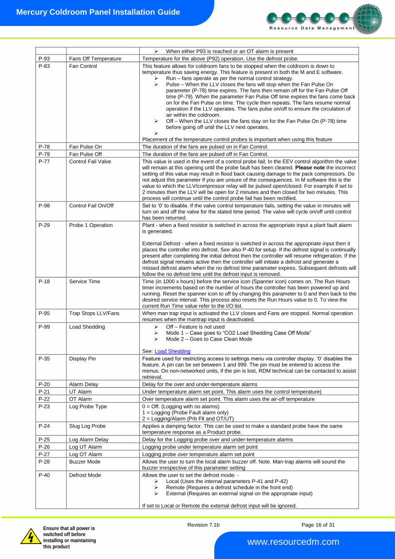
When either P93 is reached or an OT alarm is present
P-93 Fans Off Temperature Temperature for the above (P92) operation. Use the defrost probe.
P-83 Fan Control This feature allows for coldroom fans to be stopped when the coldroom is down to temperature thus saving energy. This feature is present in both the M and E software.
Run – fans operate as per the normal control strategy. Pulse – When the LLV closes the fans will stop when the Fan Pulse On
parameter (P-78) time expires. The fans then remain off for the Fan Pulse Off time (P-79). When the parameter Fan Pulse Off time expires the fans come back on for the Fan Pulse on time. The cycle then repeats. The fans resume normal operation if the LLV operates. The fans pulse on/off to ensure the circulation of air within the coldroom.
Off – When the LLV closes the fans stay on for the Fan Pulse On (P-78) time before going off until the LLV next operates.
Placement of the temperature control probes is important when using this feature
P-78 Fan Pulse On The duration of the fans are pulsed on in Fan Control.
P-79 Fan Pulse Off The duration of the fans are pulsed off in Fan Control.
P-77 Control Fail Valve This value is used in the event of a control probe fail; In the EEV control algorithm the valve will remain at this opening until the probe fault has been cleared. Please note the incorrect setting of this value may result in flood back causing damage to the pack compressors. Do not adjust this parameter if you are unsure of the consequences. In M software this is the value to which the LLV/compressor relay will be pulsed open/closed. For example if set to 2 minutes then the LLV will be open for 2 minutes and then closed for two minutes. This process will continue until the control probe fail has been rectified.
P-98 Control Fail On/Off Set to ‘0’ to disable. If the valve control temperature fails, setting the value in minutes will turn on and off the valve for the stated time period. The valve will cycle on/off until control has been returned.
P-29 Probe 1 Operation Plant - when a fixed resistor is switched in across the appropriate input a plant fault alarm is generated. External Defrost - when a fixed resistor is switched in across the appropriate input then it places the controller into defrost. See also P-40 for setup. If the defrost signal is continually present after completing the initial defrost then the controller will resume refrigeration. If the defrost signal remains active then the controller will initiate a defrost and generate a missed defrost alarm when the no defrost time parameter expires. Subsequent defrosts will follow the no defrost time until the defrost input is removed.
P-18 Service Time Time (in 1000 x hours) before the service icon (Spanner icon) comes on. The Run Hours timer increments based on the number of hours the controller has been powered up and running. Reset the spanner icon to off by changing this parameter to 0 and then back to the desired service interval. This process also resets the Run Hours value to 0. To view the current Run Time value refer to the I/O list.
P-95 Trap Stops LLV/Fans When man trap input is activated the LLV closes and Fans are stopped. Normal operation resumes when the mantrap input is deactivated.
P-99 Load Shedding Off – Feature is not used Mode 1 – Case goes to “CO2 Load Shedding Case Off Mode” Mode 2 – Goes to Case Clean Mode
See: Load Shedding
P-35 Display Pin Feature used for restricting access to settings menu via controller display. ‘0’ disables the feature. A pin can be set between 1 and 999. The pin must be entered to access the menus. On non-networked units, if the pin is lost, RDM technical can be contacted to assist retrieval.
P-20 Alarm Delay Delay for the over and under-temperature alarms
P-21 UT Alarm Under temperature alarm set point. This alarm uses the control temperature)
P-22 OT Alarm Over temperature alarm set point. This alarm uses the air-off temperature
P-23 Log Probe Type 0 = Off. (Logging with no alarms) 1 = Logging (Probe Fault alarm only) 2 = Logging/Alarm (Prb Flt and OT/UT)
P-24 Slug Log Probe Applies a damping factor. This can be used to make a standard probe have the same temperature response as a Product probe.
P-25 Log Alarm Delay Delay for the Logging probe over and under-temperature alarms
P-26 Log UT Alarm Logging probe under temperature alarm set point
P-27 Log OT Alarm Logging probe over temperature alarm set point
P-28 Buzzer Mode Allows the user to turn the local alarm buzzer off. Note. Man-trap alarms will sound the buzzer irrespective of this parameter setting
P-40 Defrost Mode Allows the user to set the defrost mode: - Local (Uses the internal parameters P-41 and P-42) Remote (Requires a defrost schedule in the front end) External (Requires an external signal on the appropriate input)
If set to Local or Remote the external defrost input will be ignored.
Revision 7.1b Page 17 of 31
Mercury Coldroom Panel Installation Guide
www.resourcedm.com
Warning
Please Note The specifications of the product detailed on this Set-Up Guide may change without notice. RDM Ltd. shall not be liable for errors or for incidental or consequential damages, directly and indirectly, in connection with the furnishing, performance or misuse of this product or document.
Ensure that all power is switched off before installing or maintaining this product
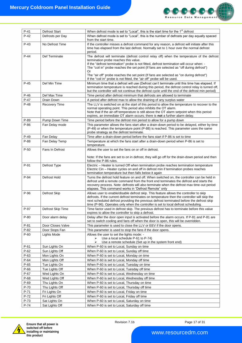
P-41 Defrost Start When defrost mode is set to “Local”, this is the start time for the 1st defrost
P-42 Defrosts per Day When defrost mode is set to “Local”, this is the number of defrosts per day equally spaced from the start time.
P-43 No Defrost Time If the controller misses a defrost command for any reason, a defrost will initiate after this time has elapsed from the last defrost. Normally set to 1 hour over the normal defrost period.
P-44 Def Terminate The defrost will terminate (defrost control relay off) when the temperature of the defrost termination probe reaches this value. If the "defrost termination" probe is not fitted, defrost termination will occur when: - The "coil in" probe reaches the set point (If fans are selected as "off during defrost") Or The "air off" probe reaches the set point (If fans are selected as "on during defrost") If the "coil in" probe is not fitted, the "air off" probe will be used.
P-45 Def Min Time Minimum time that a defrost will use (Defrost can’t terminate until this time has elapsed. If termination temperature is reached during this period, the defrost control relay is turned off, but the controller will not continue the defrost cycle until the end of the defrost min period)
P-46 Def Max Time Time period after defrost minimum that defrosts are allowed to terminate
P-47 Drain Down A period after defrost max to allow the draining of any surplus water
P-48 Recovery Time The LLV is switched on at the start of this period to allow the temperature to recover to the normal operating point. This period also inhibits the OT alarm. Note that if the air-off temperature is still above the OT alarm setpoint when this period expires, an immediate OT alarm occurs; there is not a further alarm delay.
P-89 Pump Down Time Time period before the defrost min period to allow for a pump down
P-86 Fan Delay mode This parameter allows the fans start after a drain-down period to be delayed, either by time (P-49) or when the temperature point (P-88) is reached. This parameter uses the same probe strategy as the defrost terminate.
P-49 Fan Delay Time after a drain-down period before the fans start if P-86 is set to time
P-88 Fan Delay Temp Temperature at which the fans start after a drain-down period when P-86 is set to temperature.
P-50 Fans In Defrost Allows the user to set the fans on or off in defrost. Note: If the fans are set to on in defrost, they will go off for the drain-down period and then follow the P-86 rules.
P-91 Defrost Type Electric – Heater is turned Off when termination probe reaches termination temperature Electric Cin – Heater cycles on and off in defrost min if termination probes reaches termination temperature but then falls below it again
P-94 Defrost Hold Turns the defrost hold feature on and off. When switched on, the controller can be held in defrost until a remote command from the front end terminates the defrost and starts the recovery process. Note: defrosts will also terminate when the defrost max time-out period elapses. This command works in “Defrost Remote” only
P-96 Defrost Skip Allows user to enable/disable defrost skip. This feature allows the controller to skip defrosts. If the current defrost terminates on temperature then the controller will skip the next scheduled defrost providing the previous defrost terminated before the defrost skip time (P-96). Operates only when the controller is set to local defrost scheduling.
P-97 Defrost Skip Time Time factor used in defrost skip. The previous defrost has to terminate before this value expires to allow the controller to skip a defrost.
P-80 Door alarm delay Delay after the door open input is activated before the alarm occurs. If P-81 and P-81 are set to switch cooling and fans off when the door is open, this will be overridden.
P-81 Door Closes Valve This parameter is used to close the LLV or EEV if the door opens.
P-82 Door Stops Fan This parameter is used to stop the fans if the door opens.
P-60 Lights Mode Allows the user to set the lights mode: - Use a local schedule P-61 to P-74) Use a remote schedule (Set up in the system front end)
P-61 Sun Lights On When P-60 is set to Local, Sunday on time
P-62 Sun Lights Off When P-60 is set to Local, Sunday off time
P-63 Mon Lights On When P-60 is set to Local, Monday on time
P-64 Mon Lights Off When P-60 is set to Local, Monday off time
P-65 Tue Lights On When P-60 is set to Local, Tuesday on time
P-66 Tue Lights Off When P-60 is set to Local, Tuesday off time
P-67 Wed Lights On When P-60 is set to Local, Wednesday on time
P-68 Wed Lights Off When P-60 is set to Local, Wednesday off time
P-69 Thu Lights On When P-60 is set to Local, Thursday on time
P-70 Thu Lights Off When P-60 is set to Local, Thursday off time
P-71 Fri Lights On When P-60 is set to Local, Friday on time
P-72 Fri Lights Off When P-60 is set to Local, Friday off time
P-73 Sat Lights On When P-60 is set to Local, Saturday on time
P-74 Sat Lights Off When P-60 is set to Local, Saturday off time
Revision 7.1b Page 18 of 31
Mercury Coldroom Panel Installation Guide
www.resourcedm.com
Warning
Please Note The specifications of the product detailed on this Set-Up Guide may change without notice. RDM Ltd. shall not be liable for errors or for incidental or consequential damages, directly and indirectly, in connection with the furnishing, performance or misuse of this product or document.
Ensure that all power is switched off before installing or maintaining this product
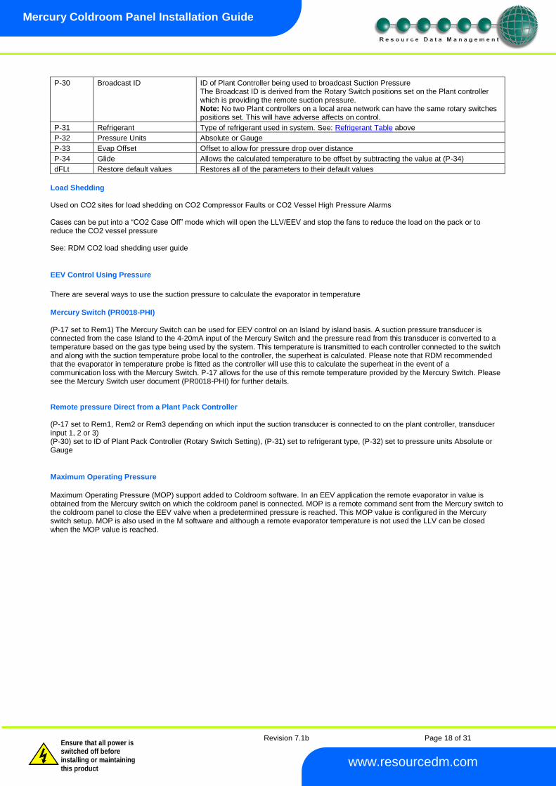
P-30 Broadcast ID ID of Plant Controller being used to broadcast Suction Pressure
The Broadcast ID is derived from the Rotary Switch positions set on the Plant controller which is providing the remote suction pressure. Note: No two Plant controllers on a local area network can have the same rotary switches positions set. This will have adverse affects on control.
P-31 Refrigerant Type of refrigerant used in system. See: Refrigerant Table above
P-32 Pressure Units Absolute or Gauge
P-33 Evap Offset Offset to allow for pressure drop over distance
P-34 Glide Allows the calculated temperature to be offset by subtracting the value at (P-34)
dFLt Restore default values Restores all of the parameters to their default values
Load Shedding Used on CO2 sites for load shedding on CO2 Compressor Faults or CO2 Vessel High Pressure Alarms Cases can be put into a “CO2 Case Off” mode which will open the LLV/EEV and stop the fans to reduce the load on the pack or to reduce the CO2 vessel pressure See: RDM CO2 load shedding user guide
EEV Control Using Pressure
There are several ways to use the suction pressure to calculate the evaporator in temperature
Mercury Switch (PR0018-PHI) (P-17 set to Rem1) The Mercury Switch can be used for EEV control on an Island by island basis. A suction pressure transducer is connected from the case Island to the 4-20mA input of the Mercury Switch and the pressure read from this transducer is converted to a temperature based on the gas type being used by the system. This temperature is transmitted to each controller connected to the switch and along with the suction temperature probe local to the controller, the superheat is calculated. Please note that RDM recommended that the evaporator in temperature probe is fitted as the controller will use this to calculate the superheat in the event of a communication loss with the Mercury Switch. P-17 allows for the use of this remote temperature provided by the Mercury Switch. Please see the Mercury Switch user document (PR0018-PHI) for further details. Remote pressure Direct from a Plant Pack Controller (P-17 set to Rem1, Rem2 or Rem3 depending on which input the suction transducer is connected to on the plant controller, transducer input 1, 2 or 3) (P-30) set to ID of Plant Pack Controller (Rotary Switch Setting), (P-31) set to refrigerant type, (P-32) set to pressure units Absolute or Gauge
Maximum Operating Pressure
Maximum Operating Pressure (MOP) support added to Coldroom software. In an EEV application the remote evaporator in value is obtained from the Mercury switch on which the coldroom panel is connected. MOP is a remote command sent from the Mercury switch to the coldroom panel to close the EEV valve when a predetermined pressure is reached. This MOP value is configured in the Mercury switch setup. MOP is also used in the M software and although a remote evaporator temperature is not used the LLV can be closed when the MOP value is reached.
Revision 7.1b Page 19 of 31
Mercury Coldroom Panel Installation Guide
www.resourcedm.com
Warning
Please Note The specifications of the product detailed on this Set-Up Guide may change without notice. RDM Ltd. shall not be liable for errors or for incidental or consequential damages, directly and indirectly, in connection with the furnishing, performance or misuse of this product or document.
Ensure that all power is switched off before installing or maintaining this product
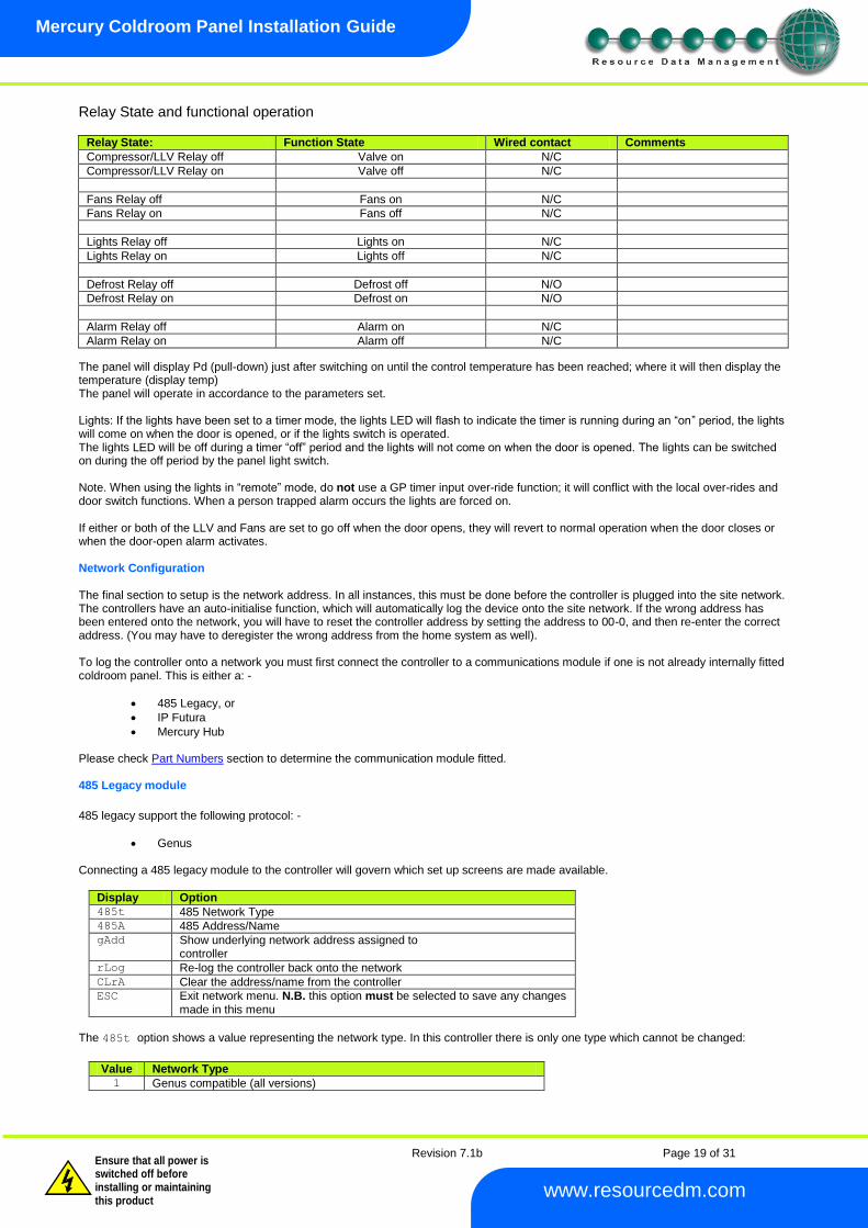
Relay State and functional operation
Relay State: Function State Wired contact Comments
Compressor/LLV Relay off Valve on N/C
Compressor/LLV Relay on Valve off N/C
Fans Relay off Fans on N/C
Fans Relay on Fans off N/C
Lights Relay off Lights on N/C
Lights Relay on Lights off N/C
Defrost Relay off Defrost off N/O
Defrost Relay on Defrost on N/O
Alarm Relay off Alarm on N/C
Alarm Relay on Alarm off N/C
The panel will display Pd (pull-down) just after switching on until the control temperature has been reached; where it will then display the temperature (display temp) The panel will operate in accordance to the parameters set. Lights: If the lights have been set to a timer mode, the lights LED will flash to indicate the timer is running during an “on” period, the lights will come on when the door is opened, or if the lights switch is operated. The lights LED will be off during a timer “off” period and the lights will not come on when the door is opened. The lights can be switched on during the off period by the panel light switch. Note. When using the lights in “remote” mode, do not use a GP timer input over-ride function; it will conflict with the local over-rides and door switch functions. When a person trapped alarm occurs the lights are forced on. If either or both of the LLV and Fans are set to go off when the door opens, they will revert to normal operation when the door closes or when the door-open alarm activates. Network Configuration The final section to setup is the network address. In all instances, this must be done before the controller is plugged into the site network. The controllers have an auto-initialise function, which will automatically log the device onto the site network. If the wrong address has been entered onto the network, you will have to reset the controller address by setting the address to 00-0, and then re-enter the correct address. (You may have to deregister the wrong address from the home system as well). To log the controller onto a network you must first connect the controller to a communications module if one is not already internally fitted coldroom panel. This is either a: -
485 Legacy, or
IP Futura
Mercury Hub Please check Part Numbers section to determine the communication module fitted. 485 Legacy module
485 legacy support the following protocol: -
Genus Connecting a 485 legacy module to the controller will govern which set up screens are made available.
Display Option 485t 485 Network Type 485A 485 Address/Name gAdd Show underlying network address assigned to
controller rLog Re-log the controller back onto the network CLrA Clear the address/name from the controller ESC Exit network menu. N.B. this option must be selected to save any changes
made in this menu
The 485t option shows a value representing the network type. In this controller there is only one type which cannot be changed:
Value Network Type 1 Genus compatible (all versions)
Revision 7.1b Page 20 of 31
Mercury Coldroom Panel Installation Guide
www.resourcedm.com
Warning
Please Note The specifications of the product detailed on this Set-Up Guide may change without notice. RDM Ltd. shall not be liable for errors or for incidental or consequential damages, directly and indirectly, in connection with the furnishing, performance or misuse of this product or document.
Ensure that all power is switched off before installing or maintaining this product
The 485A option shows a value representing either the name of the controller in a Genus compatible network.
The value shown is of the form 05-6. This means the controller would try to log onto a Genus compatible network using the name
‘RC05-6’. The following options are also available when the network type is set to Genus compatible.
The gAdd option displays (in hexadecimal format) the underlying network address assigned to the controller when it was logged onto the
network.
The rLog option allows the controller to be logged back onto the network with its current name. The ‘rLog’ message will flash for
confirmation. Press the Enter button to execute the command, Up or Down buttons to cancel. Fast Network Address Reset
The CLrA option will clear out the network address and name in the controller. The ‘ClrA’ message will flash for confirmation. Press the
Enter button to execute the command, Up or Down buttons to cancel.
To enter this mode, hold the Enter, Up and Down buttons together for approximately 3 seconds until the message CLrA appears on the
display. CLrA is the first option in the menu consisting of the following options:
Display Option
CLrA Clear the address/name from the controller
ESC Exit Setup mode
Pressing the Enter button to select the CLrA option will cause the ‘CLrA’ message to flash for confirmation, if the network type is set to
Genus compatible. Press the Enter button to execute the command, Up or Down buttons to cancel. If the network type is not set to
Genus compatible then the ClrA message will not flash and the ESC option can be used to exit the menu.
IP Futura module
In an IP system there are two options
IP-L
IP-r IP-L allows you to fix an IP address into the controller, which you would use when you are connecting the controllers onto a customer’s local area network. This would allow the customer to view each controller using Internet Explorer IP-r allows you to give each controller on the system a unique number. This number is then allocated a dynamic IP address by the system DHCP server (such as the RDM Data Director)
IP-L To configure the communication module for IP-L, set all three rotary switches to zero. The module should then be connected to the controller.
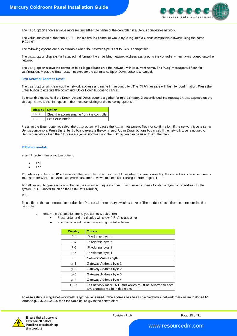
1. nEt. From the function menu you can now select nEt
Press enter and the display will show “IP-L”, press enter
You can now set the address using the table below
Display Option
IP-1 IP Address byte 1
IP-2 IP Address byte 2
IP-3 IP Address byte 3
IP-4 IP Address byte 4
nL Network Mask Length
gt-1 Gateway Address byte 1
gt-2 Gateway Address byte 2
gt-3 Gateway Address byte 3
gt-4 Gateway Address byte 4
ESC Exit network menu. N.B. this option must be selected to save any changes made in this menu
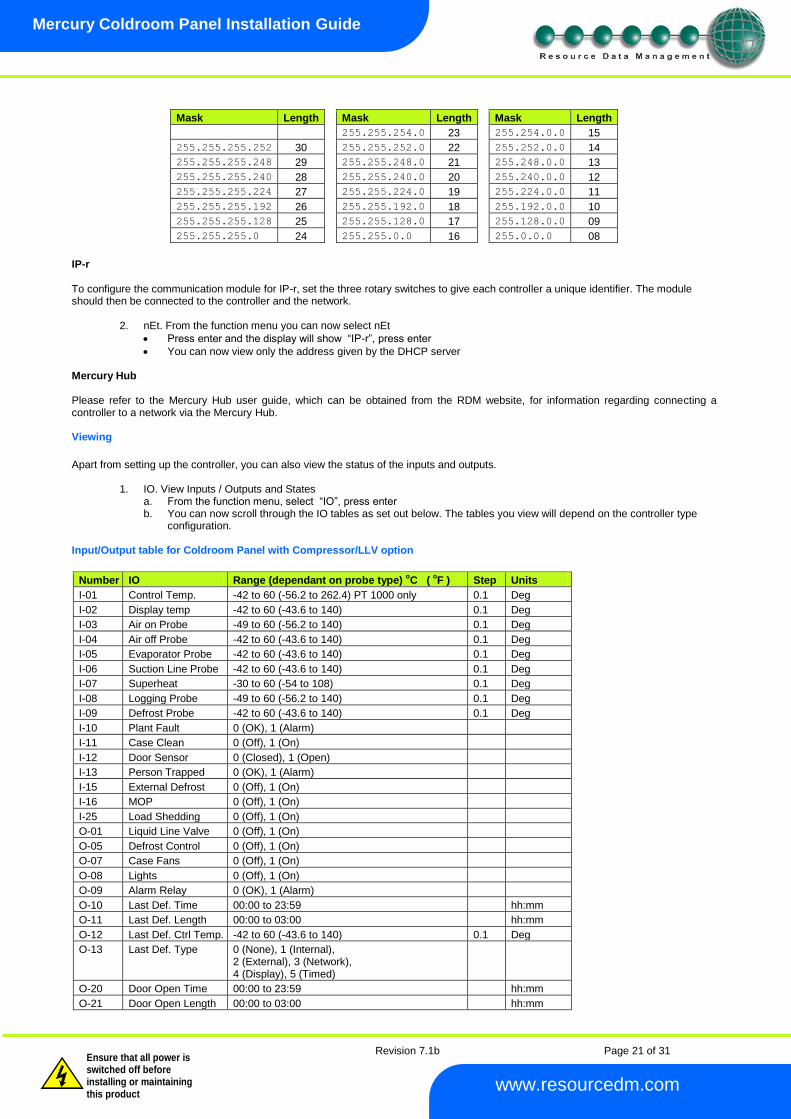
To ease setup, a single network mask length value is used. If the address has been specified with a network mask value in dotted IP format e.g. 255.255.255.0 then the table below gives the conversion:
Revision 7.1b Page 21 of 31
Mercury Coldroom Panel Installation Guide
www.resourcedm.com
Warning
Please Note The specifications of the product detailed on this Set-Up Guide may change without notice. RDM Ltd. shall not be liable for errors or for incidental or consequential damages, directly and indirectly, in connection with the furnishing, performance or misuse of this product or document.
Ensure that all power is switched off before installing or maintaining this product
Mask Length Mask Length Mask Length
255.255.254.0 23 255.254.0.0 15
255.255.255.252 30 255.255.252.0 22 255.252.0.0 14
255.255.255.248 29 255.255.248.0 21 255.248.0.0 13
255.255.255.240 28 255.255.240.0 20 255.240.0.0 12
255.255.255.224 27 255.255.224.0 19 255.224.0.0 11
255.255.255.192 26 255.255.192.0 18 255.192.0.0 10
255.255.255.128 25 255.255.128.0 17 255.128.0.0 09
255.255.255.0 24 255.255.0.0 16 255.0.0.0 08
IP-r To configure the communication module for IP-r, set the three rotary switches to give each controller a unique identifier. The module should then be connected to the controller and the network.
2. nEt. From the function menu you can now select nEt
Press enter and the display will show “IP-r”, press enter
You can now view only the address given by the DHCP server Mercury Hub Please refer to the Mercury Hub user guide, which can be obtained from the RDM website, for information regarding connecting a controller to a network via the Mercury Hub. Viewing
Apart from setting up the controller, you can also view the status of the inputs and outputs.
1. IO. View Inputs / Outputs and States a. From the function menu, select “IO”, press enter b. You can now scroll through the IO tables as set out below. The tables you view will depend on the controller type
configuration. Input/Output table for Coldroom Panel with Compressor/LLV option
Number IO Range (dependant on probe type)
oC (
oF ) Step Units
I-01 Control Temp. -42 to 60 (-56.2 to 262.4) PT 1000 only 0.1 Deg
I-02 Display temp -42 to 60 (-43.6 to 140) 0.1 Deg
I-03 Air on Probe -49 to 60 (-56.2 to 140) 0.1 Deg
I-04 Air off Probe -42 to 60 (-43.6 to 140) 0.1 Deg
I-05 Evaporator Probe -42 to 60 (-43.6 to 140) 0.1 Deg
I-06 Suction Line Probe -42 to 60 (-43.6 to 140) 0.1 Deg
I-07 Superheat -30 to 60 (-54 to 108) 0.1 Deg
I-08 Logging Probe -49 to 60 (-56.2 to 140) 0.1 Deg
I-09 Defrost Probe -42 to 60 (-43.6 to 140) 0.1 Deg
I-10 Plant Fault 0 (OK), 1 (Alarm)
I-11 Case Clean 0 (Off), 1 (On)
I-12 Door Sensor 0 (Closed), 1 (Open)
I-13 Person Trapped 0 (OK), 1 (Alarm)
I-15 External Defrost 0 (Off), 1 (On)
I-16 MOP 0 (Off), 1 (On)
I-25 Load Shedding 0 (Off), 1 (On)
O-01 Liquid Line Valve 0 (Off), 1 (On)
O-05 Defrost Control 0 (Off), 1 (On)
O-07 Case Fans 0 (Off), 1 (On)
O-08 Lights 0 (Off), 1 (On)
O-09 Alarm Relay 0 (OK), 1 (Alarm)
O-10 Last Def. Time 00:00 to 23:59 hh:mm
O-11 Last Def. Length 00:00 to 03:00 hh:mm
O-12 Last Def. Ctrl Temp. -42 to 60 (-43.6 to 140) 0.1 Deg
O-13 Last Def. Type 0 (None), 1 (Internal), 2 (External), 3 (Network), 4 (Display), 5 (Timed)
O-20 Door Open Time 00:00 to 23:59 hh:mm
O-21 Door Open Length 00:00 to 03:00 hh:mm
Revision 7.1b Page 22 of 31
Mercury Coldroom Panel Installation Guide
www.resourcedm.com
Warning
Please Note The specifications of the product detailed on this Set-Up Guide may change without notice. RDM Ltd. shall not be liable for errors or for incidental or consequential damages, directly and indirectly, in connection with the furnishing, performance or misuse of this product or document.
Ensure that all power is switched off before installing or maintaining this product
O-30 Set Point Offset -49 to 60 (-56.2 to 140) 0.1 Deg
O-32 Timer 0 (Off), 1 (On)
O-18 Run Time 0 to 128 1 K Hrs
S-01 Control State 0 (Stabilise), 1 (Normal), 2 (Defrost Min), 3 (Defrost Max), 4 (Drain Down), 5 Fan Delay 6 (Recovery), 7 (OT Alarm), 8 (UT Alarm), 9 (Fans Only), 10 (Lights Only), 11 (Case Off), 12 (Pump_Down), 13 (Df Hold), 14 (Load Shedding)
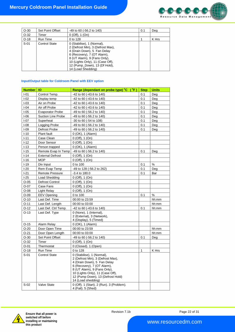
Input/Output table for Coldroom Panel with EEV option
Number IO Range (dependant on probe type)
oC (
oF ) Step Units
I-01 Control Temp. -42 to 60 (-43.6 to 140) 0.1 Deg
I-02 Display temp -42 to 60 (-43.6 to 140) 0.1 Deg
I-03 Air on Probe -42 to 60 (-43.6 to 140) 0.1 Deg
I-04 Air off Probe -42 to 60 (-43.6 to 140) 0.1 Deg
I-05 Evaporator Probe -49 to 60 (-56.2 to 140) 0.1 Deg
I-06 Suction Line Probe -49 to 60 (-56.2 to 140) 0.1 Deg
I-07 Superheat -30 to 60 (-54 to 108) 0.1 Deg
I-08 Logging Probe -49 to 60 (-56.2 to 140) 0.1 Deg
I-09 Defrost Probe -49 to 60 (-56.2 to 140) 0.1 Deg
I-10 Plant fault 0 (OK), 1 (Alarm)
I-11 Case Clean 0 (Off), 1 (On)
I-12 Door Sensor 0 (Off), 1 (On)
I-13 Person trapped 0 (OK), 1 (Alarm)
I-15 Remote Evap In Temp -49 to 60 (-56.2 to 140) 0.1 Deg
I-14 External Defrost 0 (Off), 1 (On)
I-16 MOP 0 (Off), 1 (On)
I-19 Div Input 0 to 100 0.1 %
I-20 Rem Evap Temp -49 to 128 (-56.2 to 262) 0.1 Deg
I-21 Remote Pressure -3.4 to 180.0 0.1 Bar
I-25 Load Shedding 0 (Off), 1 (On)
O-05 Defrost Control 0 (Off), 1 (On)
O-07 Case Fans 0 (Off), 1 (On)
O-08 Light Relay 0 (Off), 1 (On)
O-09 EEV Opening 0 to 100 0.1 %
O-10 Last Def. Time 00:00 to 23:59 hh:mm
O-11 Last Def. Length 00:00 to 03:00 hh:mm
O-12 Last Def. Ctrl Temp. -42 to 60 (-43.6 to 140) 0.1 hh:mm
O-13 Last Def. Type 0 (None), 1 (Internal), 2 (External), 3 (Network), 4 (Display), 5 (Timed)
O-15 Alarm Relay 0 (OK), 1 (Alarm)
O-20 Door Open Time 00:00 to 23:59 hh:mm
O-21 Door Open Length 00:00 to 03:00 hh:mm
O-30 Set Point Offset -49 to 60 (-56.2 to 140) 0.1 Deg
O-32 Timer 0 (Off), 1 (On)
O-01 Thermostat 0 (Closed). 1 (Open)
O-18 Run Time 0 to 128 1 K Hrs
S-01 Control State 0 (Stabilise), 1 (Normal), 2 (Defrost Min), 3 (Defrost Max), 4 (Drain Down), 5 Fan Delay 6 (Recovery), 7 (OT Alarm), 8 (UT Alarm), 9 (Fans Only), 10 (Lights Only), 11 (Case Off), 12 (Pump Down), 13 (Defrost Hold) 14 (Load shedding)
S-02 Valve State 0 (Off). 1 (Start). 2 (Run). 3 (Problem). 4 (Fail). 5 (Shed)
Revision 7.1b Page 23 of 31
Mercury Coldroom Panel Installation Guide
www.resourcedm.com
Warning
Please Note The specifications of the product detailed on this Set-Up Guide may change without notice. RDM Ltd. shall not be liable for errors or for incidental or consequential damages, directly and indirectly, in connection with the furnishing, performance or misuse of this product or document.
Ensure that all power is switched off before installing or maintaining this product
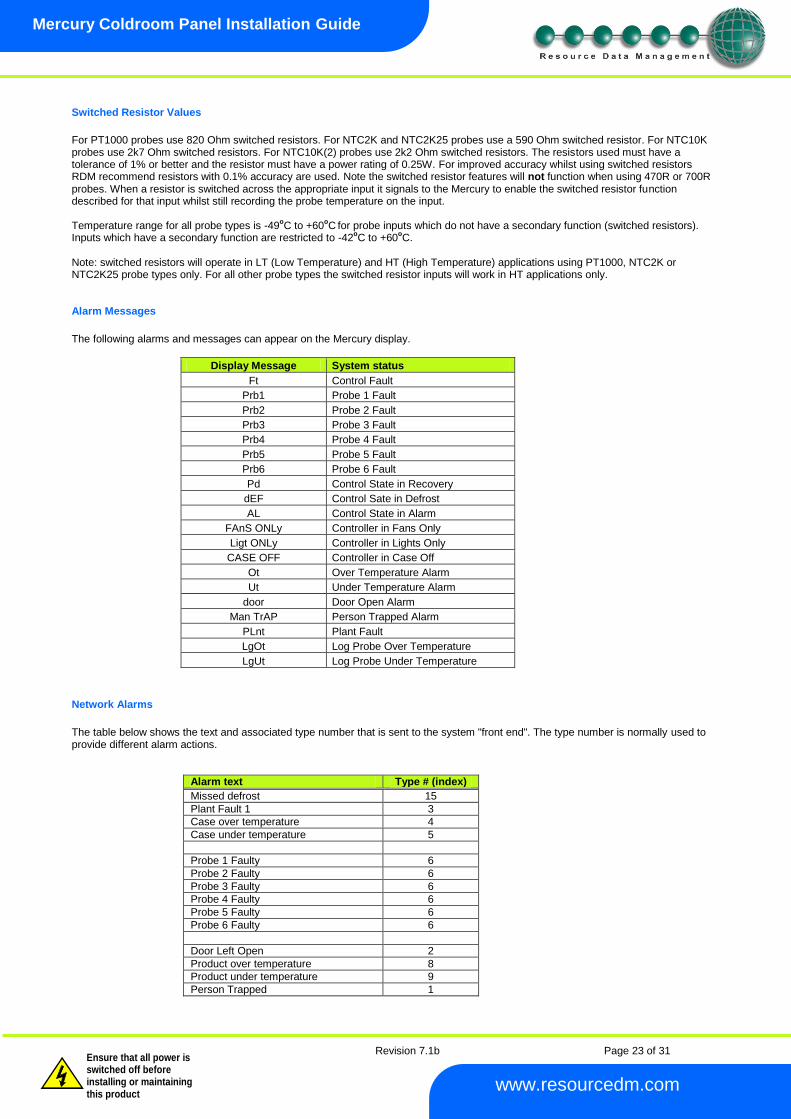
Switched Resistor Values
For PT1000 probes use 820 Ohm switched resistors. For NTC2K and NTC2K25 probes use a 590 Ohm switched resistor. For NTC10K probes use 2k7 Ohm switched resistors. For NTC10K(2) probes use 2k2 Ohm switched resistors. The resistors used must have a tolerance of 1% or better and the resistor must have a power rating of 0.25W. For improved accuracy whilst using switched resistors RDM recommend resistors with 0.1% accuracy are used. Note the switched resistor features will not function when using 470R or 700R probes. When a resistor is switched across the appropriate input it signals to the Mercury to enable the switched resistor function described for that input whilst still recording the probe temperature on the input. Temperature range for all probe types is -49
oC to +60
oC
for probe inputs which do not have a secondary function (switched resistors).
Inputs which have a secondary function are restricted to -42oC to +60
oC.
Note: switched resistors will operate in LT (Low Temperature) and HT (High Temperature) applications using PT1000, NTC2K or NTC2K25 probe types only. For all other probe types the switched resistor inputs will work in HT applications only. Alarm Messages
The following alarms and messages can appear on the Mercury display.
Display Message System status
Ft Control Fault
Prb1 Probe 1 Fault
Prb2 Probe 2 Fault
Prb3 Probe 3 Fault
Prb4 Probe 4 Fault
Prb5 Probe 5 Fault
Prb6 Probe 6 Fault
Pd Control State in Recovery
dEF Control Sate in Defrost
AL Control State in Alarm
FAnS ONLy Controller in Fans Only
Ligt ONLy Controller in Lights Only
CASE OFF Controller in Case Off
Ot Over Temperature Alarm
Ut Under Temperature Alarm
door Door Open Alarm
Man TrAP Person Trapped Alarm
PLnt Plant Fault
LgOt Log Probe Over Temperature
LgUt Log Probe Under Temperature
Network Alarms
The table below shows the text and associated type number that is sent to the system "front end". The type number is normally used to provide different alarm actions.
Alarm text Type # (index)
Missed defrost 15
Plant Fault 1 3
Case over temperature 4
Case under temperature 5
Probe 1 Faulty 6
Probe 2 Faulty 6
Probe 3 Faulty 6
Probe 4 Faulty 6
Probe 5 Faulty 6
Probe 6 Faulty 6
Door Left Open 2
Product over temperature 8
Product under temperature 9
Person Trapped 1
Revision 7.1b Page 24 of 31
Mercury Coldroom Panel Installation Guide
www.resourcedm.com
Warning
Please Note The specifications of the product detailed on this Set-Up Guide may change without notice. RDM Ltd. shall not be liable for errors or for incidental or consequential damages, directly and indirectly, in connection with the furnishing, performance or misuse of this product or document.
Ensure that all power is switched off before installing or maintaining this product
Modifying controller states During normal operation you can change the following states from the function menu
Fans Only “FAnS” Selecting the Fans Only option will put the controller into the Fans Only state if the current state is not Fans Only. If the current state is Fans Only then the controller will change to the Normal state. Selecting this option will exit the setup menu automatically. The display will show “FAnS OnLy” If a remote display with key switch is being used, this function can be invoked by turning the key switch to the fans only position (90 degrees clockwise) with parameter P85 set to "fans" Case Off “CASE” Selecting the Case Off option will put the controller into the Case Off state if the current state is not Case Off. If the current state is Case Off then the controller will change to the Normal state. Selecting this option will exit the setup menu automatically. The display will show “CASE OFF” If a remote display with key switch is being used, this function can be invoked by turning the key switch to the case-off position. (Clockwise 90 degrees) with parameter P85 set to "case"
Lights Only “Ligt” Selecting the Lights Only option will put the controller into the Lights Only state if the current state is not Lights Only. If the current state is Lights Only then the controller will change to the Normal state. Selecting this option will exit the setup menu automatically. The display will show “Ligt OnLy” Note. When lights are being used in “Remote” mode with a timing channel: - If the controller goes offline, the lights are turned ON after a delay of 5 minutes. The lights will stay on until the controller comes back on-line where they will revert to the state of the timing channel being used.
Probe Offset This feature allows each probe value to be modified by an “offset”. Offset values are from -10
OC (-18
OF) to +10
OC (+18
OF) and on a
channel basis. Example C1 = Probe 1.
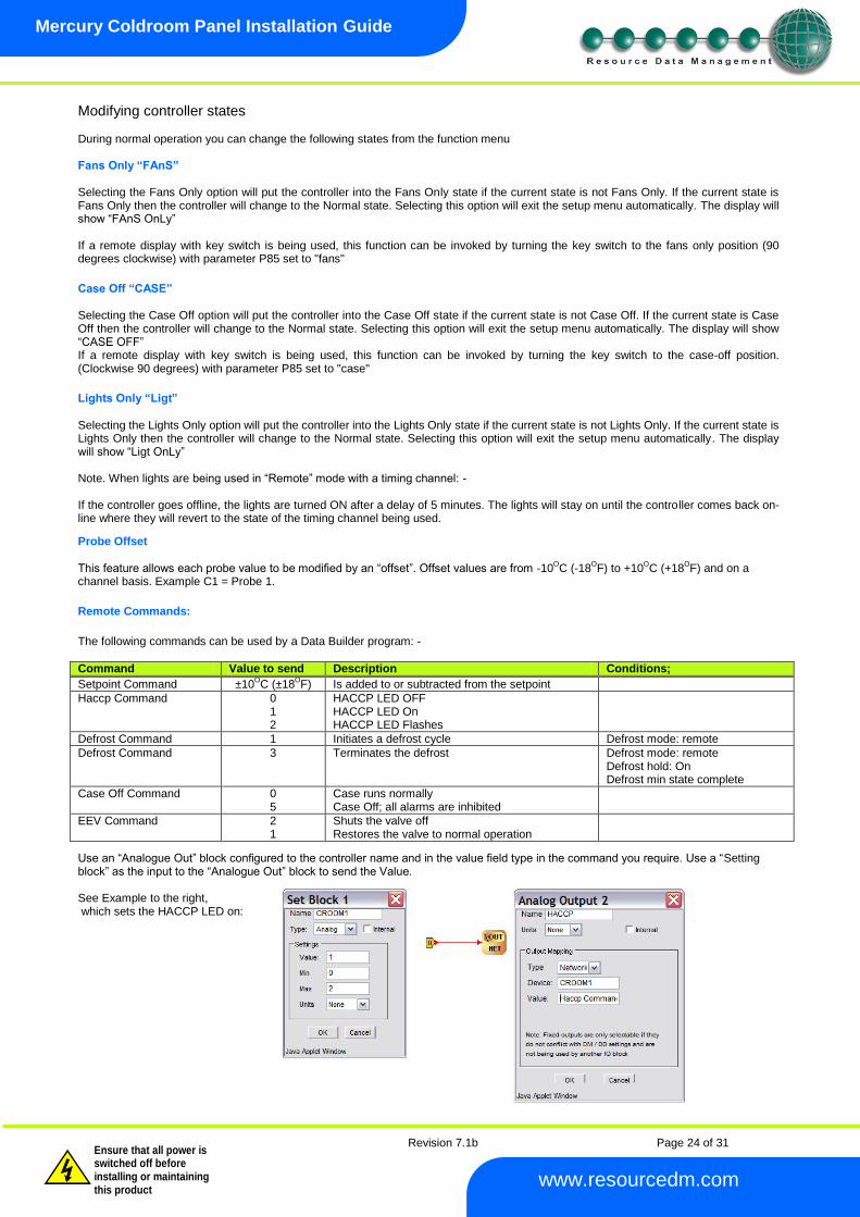
Remote Commands:
The following commands can be used by a Data Builder program: -
Command Value to send Description Conditions;
Setpoint Command ±10OC (±18
OF) Is added to or subtracted from the setpoint
Haccp Command 0 1 2
HACCP LED OFF HACCP LED On HACCP LED Flashes
Defrost Command 1 Initiates a defrost cycle Defrost mode: remote
Defrost Command 3 Terminates the defrost Defrost mode: remote Defrost hold: On Defrost min state complete
Case Off Command 0 5
Case runs normally Case Off; all alarms are inhibited
EEV Command 2 1
Shuts the valve off Restores the valve to normal operation
Use an “Analogue Out” block configured to the controller name and in the value field type in the command you require. Use a “Setting block” as the input to the “Analogue Out” block to send the Value. See Example to the right, which sets the HACCP LED on:
Revision 7.1b Page 25 of 31
Mercury Coldroom Panel Installation Guide
www.resourcedm.com
Warning
Please Note The specifications of the product detailed on this Set-Up Guide may change without notice. RDM Ltd. shall not be liable for errors or for incidental or consequential damages, directly and indirectly, in connection with the furnishing, performance or misuse of this product or document.
Ensure that all power is switched off before installing or maintaining this product
Specification Power requirements Supply Voltage Range: 100 - 240 Vac ±10% Supply Frequency: 50 - 60 Hz Maximum supply current: 40 Amps Operating temperature range: +5
0C to +50
0C
Operating Humidity: 80% maximum Storage temperature range: -20
0C to +65
0C
Environmental: Indoor use at altitudes up to 2000m, Pollution Degree 1, Voltage fluctuations not to exceed ±10% of nominal voltage Size: 240mm (W) x 300mm (H) x 140mm (D) Weight: 2.2 Kilograms Safety: EN61010 This device MUST be earthed EMC: EN61326; 1997 +Amdt. A1; 1998 Ventilation: There is no requirement for forced cooling ventilation The host equipment must provide a suitable external over-current protection device such as: - Fuse: 40A 240 Vac Antisurge (T) HRC conforming to IEC 60127 Or MCB: 40A, 240 VAC Type C conforming to BS EN 60898 IP Rating IP 40 The host equipment must provide adequate protection against contact to hazardous live parts. Maximum Output Loads
Note in later Coldroom panel hardware revisions, Revision 2, the Compressor/LLV, Fans and Defrost ratings have been revised. Please view the appropriate listing, shown below, depending on the hardware revision in use. A visual inspection of the Coldroom panel must take place to determine the hardware revision. A label is affixed alongside the relay outputs highlighting the current rating in Amps. Note in Revision 2 the Compressor/LLV and Defrost MCB or Fuse can be interchanged to allow the higher rated MCB or Fuse to be used on the Compressor/LLV relay output and the lower rated MCB or fuse to be used on the Fans relay output. Please see Appendix 1 Revision 1 (Earlier Hardware) Compressor/LLV: 15A (non inductive) 8A CosФ=0.4: Motor Load (CosФ=0.6) ½ HP Switched Output Voltage: Same as supply voltage EEV: 5A (non inductive) 2A CosФ=0.4 Switched Output Voltage: Same as supply voltage Defrost: 15A (non inductive) 8A CosФ=0.4 Switched Output Voltage: Same as supply voltage Fans: 10A (non inductive) 8A CosФ=0.4 Switched Output Voltage: Same as supply voltage Lights: 6A (non inductive) 6A CosФ=0.4 Switched Output Voltage: Same as supply voltage Out 1: 5A Permanent Output Voltage: Same as supply voltage Out 2: 1A Permanent Output Voltage: Same as supply voltage
Revision 2 Compressor/LLV: 10A (non inductive) User configuration dependant see Appendix 1
8A CosФ=0.4: Motor Load (CosФ=0.6) ½ HP Switched Output Voltage: Same as supply voltage EEV: 5A (non inductive) 2A CosФ=0.4 Switched Output Voltage: Same as supply voltage Defrost: 20A (non inductive) User configuration dependant see Appendix 1
8A CosФ=0.4 Switched Output Voltage: Same as supply voltage Fans: 8A (non inductive) 8A CosФ=0.4 Switched Output Voltage: Same as supply voltage
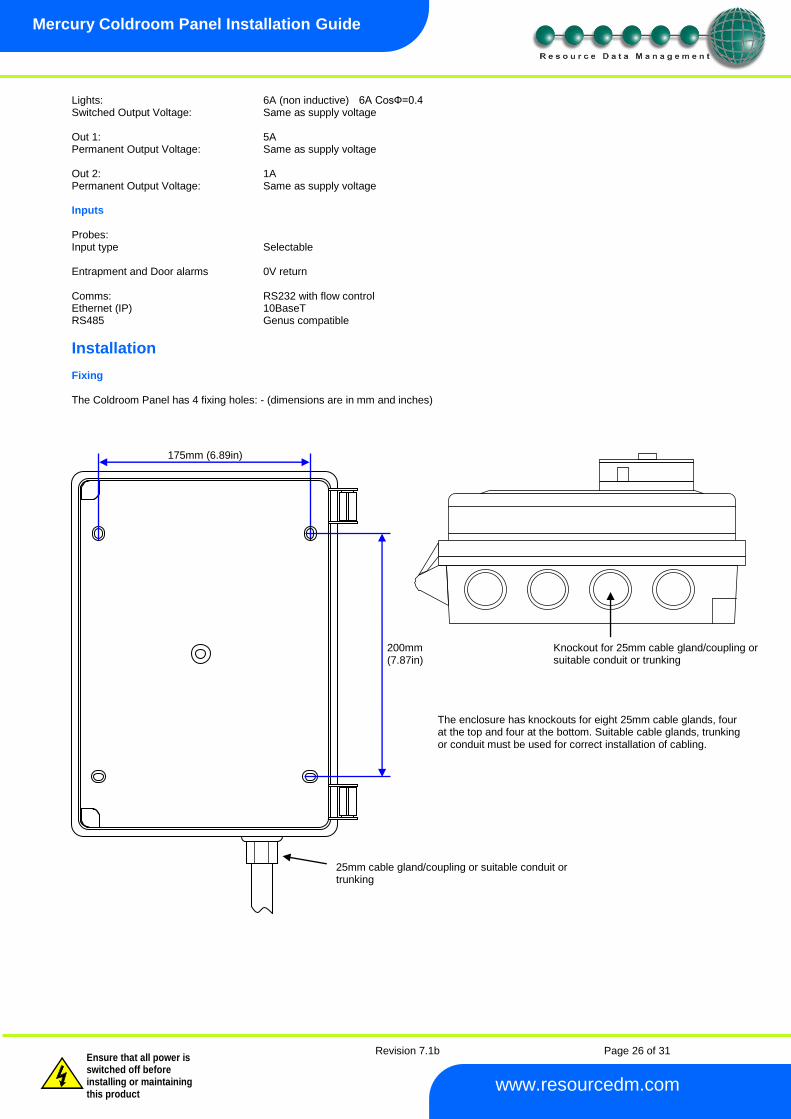
Revision 7.1b Page 26 of 31
Mercury Coldroom Panel Installation Guide
www.resourcedm.com
Warning
Please Note The specifications of the product detailed on this Set-Up Guide may change without notice. RDM Ltd. shall not be liable for errors or for incidental or consequential damages, directly and indirectly, in connection with the furnishing, performance or misuse of this product or document.
Ensure that all power is switched off before installing or maintaining this product
Lights: 6A (non inductive) 6A CosФ=0.4 Switched Output Voltage: Same as supply voltage Out 1: 5A Permanent Output Voltage: Same as supply voltage Out 2: 1A Permanent Output Voltage: Same as supply voltage Inputs Probes: Input type Selectable Entrapment and Door alarms 0V return Comms: RS232 with flow control Ethernet (IP) 10BaseT RS485 Genus compatible
Installation Fixing The Coldroom Panel has 4 fixing holes: - (dimensions are in mm and inches)
200mm (7.87in)
175mm (6.89in)
Knockout for 25mm cable gland/coupling or suitable conduit or trunking
25mm cable gland/coupling or suitable conduit or trunking
The enclosure has knockouts for eight 25mm cable glands, four at the top and four at the bottom. Suitable cable glands, trunking or conduit must be used for correct installation of cabling.
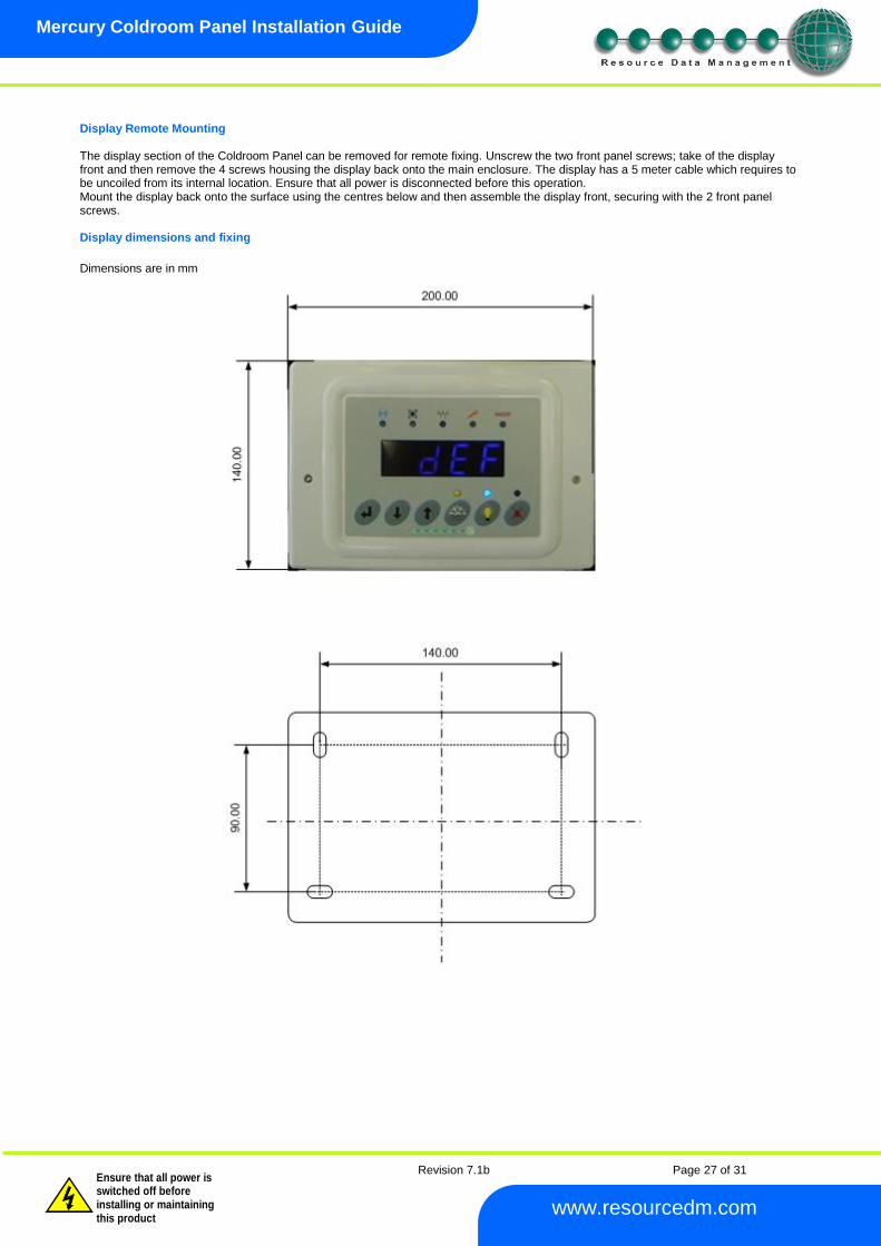
Revision 7.1b Page 27 of 31
Mercury Coldroom Panel Installation Guide
www.resourcedm.com
Warning
Please Note The specifications of the product detailed on this Set-Up Guide may change without notice. RDM Ltd. shall not be liable for errors or for incidental or consequential damages, directly and indirectly, in connection with the furnishing, performance or misuse of this product or document.
Ensure that all power is switched off before installing or maintaining this product
Display Remote Mounting The display section of the Coldroom Panel can be removed for remote fixing. Unscrew the two front panel screws; take of the display front and then remove the 4 screws housing the display back onto the main enclosure. The display has a 5 meter cable which requires to be uncoiled from its internal location. Ensure that all power is disconnected before this operation. Mount the display back onto the surface using the centres below and then assemble the display front, securing with the 2 front panel screws. Display dimensions and fixing
Dimensions are in mm
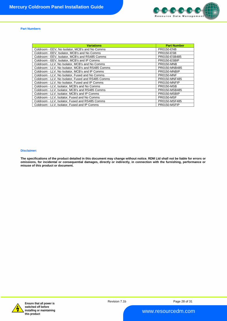
Revision 7.1b Page 28 of 31
Mercury Coldroom Panel Installation Guide
www.resourcedm.com
Warning
Please Note The specifications of the product detailed on this Set-Up Guide may change without notice. RDM Ltd. shall not be liable for errors or for incidental or consequential damages, directly and indirectly, in connection with the furnishing, performance or misuse of this product or document.
Ensure that all power is switched off before installing or maintaining this product
Part Numbers
Variations Part Number
Coldroom - EEV, No Isolator, MCB's and No Comms PR0150-ENB
Coldroom - EEV, Isolator, MCB's and No Comms PR0150-ESB
Coldroom - EEV, Isolator, MCB's and RS485 Comms PR0150-ESB485
Coldroom - EEV, Isolator, MCB's and IP Comms PR0150-ESBIP
Coldroom - LLV, No Isolator, MCB's and No Comms PR0150-MNB
Coldroom - LLV, No Isolator, MCB's and RS485 Comms PR0150-MNB485
Coldroom - LLV, No Isolator, MCB's and IP Comms PR0150-MNBIP
Coldroom - LLV, No Isolator, Fused and No Comms PR0150-MNF
Coldroom - LLV, No Isolator, Fused and RS485 Comms PR0150-MNF485
Coldroom - LLV, No Isolator, Fused and IP Comms PR0150-MNFIP
Coldroom - LLV, Isolator, MCB's and No Comms PR0150-MSB
Coldroom - LLV, Isolator, MCB's and RS485 Comms PR0150-MSB485
Coldroom - LLV, Isolator, MCB's and IP Comms PR0150-MSBIP
Coldroom - LLV, Isolator, Fused and No Comms PR0150-MSF
Coldroom - LLV, Isolator, Fused and RS485 Comms PR0150-MSF485
Coldroom - LLV, Isolator, Fused and IP Comms PR0150-MSFIP
Disclaimer:
The specifications of the product detailed in this document may change without notice. RDM Ltd shall not be liable for errors or omissions, for incidental or consequential damages, directly or indirectly, in connection with the furnishing, performance or misuse of this product or document.
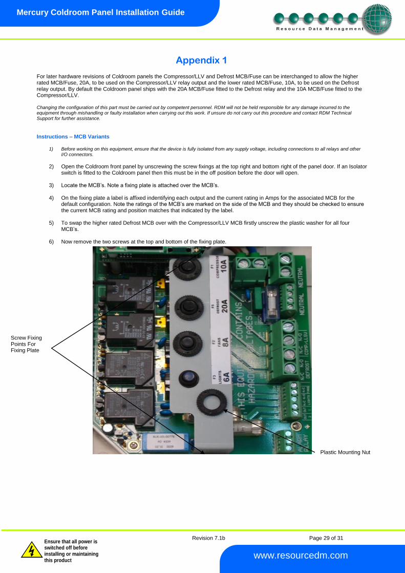
Revision 7.1b Page 29 of 31
Mercury Coldroom Panel Installation Guide
www.resourcedm.com
Warning
Please Note The specifications of the product detailed on this Set-Up Guide may change without notice. RDM Ltd. shall not be liable for errors or for incidental or consequential damages, directly and indirectly, in connection with the furnishing, performance or misuse of this product or document.
Ensure that all power is switched off before installing or maintaining this product
Appendix 1 For later hardware revisions of Coldroom panels the Compressor/LLV and Defrost MCB/Fuse can be interchanged to allow the higher rated MCB/Fuse, 20A, to be used on the Compressor/LLV relay output and the lower rated MCB/Fuse, 10A, to be used on the Defrost relay output. By default the Coldroom panel ships with the 20A MCB/Fuse fitted to the Defrost relay and the 10A MCB/Fuse fitted to the Compressor/LLV. Changing the configuration of this part must be carried out by competent personnel. RDM will not be held responsible for any damage incurred to the equipment through mishandling or faulty installation when carrying out this work. If unsure do not carry out this procedure and contact RDM Technical Support for further assistance.
Instructions – MCB Variants
1) Before working on this equipment, ensure that the device is fully isolated from any supply voltage, including connections to all relays and other I/O connectors.
2) Open the Coldroom front panel by unscrewing the screw fixings at the top right and bottom right of the panel door. If an Isolator
switch is fitted to the Coldroom panel then this must be in the off position before the door will open.
3) Locate the MCB’s. Note a fixing plate is attached over the MCB’s.
4) On the fixing plate a label is affixed indentifying each output and the current rating in Amps for the associated MCB for the default configuration. Note the ratings of the MCB’s are marked on the side of the MCB and they should be checked to ensure the current MCB rating and position matches that indicated by the label.
5) To swap the higher rated Defrost MCB over with the Compressor/LLV MCB firstly unscrew the plastic washer for all four MCB’s.
6) Now remove the two screws at the top and bottom of the fixing plate.
Plastic Mounting Nut
Screw Fixing Points For Fixing Plate

Revision 7.1b Page 30 of 31
Mercury Coldroom Panel Installation Guide
www.resourcedm.com
Warning
Please Note The specifications of the product detailed on this Set-Up Guide may change without notice. RDM Ltd. shall not be liable for errors or for incidental or consequential damages, directly and indirectly, in connection with the furnishing, performance or misuse of this product or document.
Ensure that all power is switched off before installing or maintaining this product
7) Remove the fixing plate. Swap the MCB in position “F5 Defrost” to “F1 Compressor/LLSV” and the MCB from “F1
Compressor/LLSV” to “F5 Defrost” taking note of the orientation of the MCB. The image below shows the view of the Coldroom with the fixing plate removed.
8) Ensure the MCB’s are securely fitted and the desired rated MCB’s are in the appropriate positions before re-inserting the fixing plate.
9) Now secure the fixing plate using the previously removed screws.
10) Reattach the plastic washers to the MCB’s.
11) A secondary label is supplied with the Coldroom panel and must be affixed to indicate that the MCB positions and therefore ratings have changed for the Compressor/LLV and Defrost MCB.
12) Close the Coldroom panel door and secure the front panel via the two screw fixings.
Warning : Only the Compressor/LLV and Defrost MCB positions are interchangeable. No other MCB positions can be altered.
Instructions – Fuse Variants
1) Before working on this equipment, ensure that the device is fully isolated from any supply voltage, including connections to all relays and other
I/O connectors.
2) Open the Coldroom front panel by unscrewing the screw fixings at the top right and bottom right of the panel door. If an Isolator
switch is fitted to the Coldroom panel then this must be in the off position before the door will open.
3) Locate the Fused outputs.
4) Look at the PCB screen print to identify each output and the associated Fuse. Note the ratings of the Fuse are marked on each Fuse and they should be checked to ensure the current Fuse rating is correct for the position in which the Fuse is fitted.
5) To swap the higher rated Defrost Fuse over with the Compressor/LLV Fuse firstly remove the rubber cover on each Defrost and Compressor/LLV Fuse.
6) Now remove and swap the Fuse in position “F5 Defrost” to “F1 Compressor/LLSV” and the Fuse from “F1 Compressor/LLSV”
to “F5 Defrost”.
7) Ensure the Fuses are securely fitted and the desired rated Fuse is in the appropriate position.
8) Now reattached the rubber cover over each Fuse ensuring the fuse and holder is fully covered.
9) Close the Coldroom panel door and secure the front panel via the two screw fixings.
Warning : Only the Compressor/LLV and Defrost Fuse positions are interchangeable. No other Fuse positions can be altered.
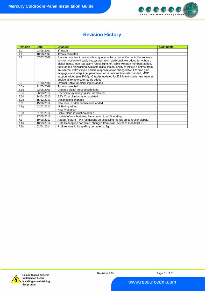
Revision 7.1b Page 31 of 31
Mercury Coldroom Panel Installation Guide
www.resourcedm.com
Warning
Please Note The specifications of the product detailed on this Set-Up Guide may change without notice. RDM Ltd. shall not be liable for errors or for incidental or consequential damages, directly and indirectly, in connection with the furnishing, performance or misuse of this product or document.
Ensure that all power is switched off before installing or maintaining this product
Revision History Revision Date Changes Comments
1.0 03/08/2007 1st Issue
1.1 10/08/2007 Typo’s corrected
6.2 07/07/2008 Revision number in revision history now reflects that of the controller software version, option to disable buzzer operation, additional text added for onboard digital inputs, man trap alarm forces lights on, table with part numbers added, table added highlighting available digital inputs, ability to initiate a defrost from an external defrost input added, response on/off changed to EEV prop gain, integ gain and integ time, parameter for remote suction select added, MOP support added (see P-30), IO tables updated for E & M to include new features, additional remote commands added.
6.3 31/10/2008 Internal Cable for alarm inputs added
6.3a 21/05/2009 Typo’s corrected
6.3b 22/06/2009 Updated digital input descriptions.
6.3c 26/03/2010 Revised relay ratings guide introduced.
6.3d 14/04/2010 EEV Control information updated.
6.3e 15/12/2011 Descriptions changed
6.3f 15/06/2012 New look, RS485 connections added
6.3g 02/07/2012 IP Rating added New Processor
6.3h 21/11/2012 Cable gland instruction added.
7.0 17/05/2013 Update of new features, Fan control, Load Shedding
7.1 19/09/2013 Added Feature – Pin restrictions on accessing menus on controller display
7.1a 10/03/2014 P-30 Description corrected, changed from evap. select to broadcast ID
7.1b 02/04/2014 P-19 removed, lits spelling corrected to ligt.