Embed Size (px)
Citation preview
This electric kit has to be installed by a professional workshop or a suitable qualified person.The installation instructions must have been read and fully understood before the start of any installation. Please contact your wiring kit provider or the hotline shown in the footer should you need assistance!Make sure the vehicle is approved/homologated by the manufacturer to tow a trailer! Also please check that there is a definite compatibility between this vehicle and the electric kit!Following the installation of the electric kit, the fitting instructions should be kept together with the vehicle service document and vehicle handbook. The fitting instructions contain important information relating to the use and function of the towing kit as well as for any diagnostic or activation process, that might have to be repeated in the future (e.g. after the performance of a vehicle software update).All warranty claims will be forfeited if the electric kit or components contained therein are used incorrectly or modified. If a towing socket adaptor has been used to connect to the trailer or bike rack, this must be removed from the trailer socket once the trailer or bike rack has been disconnected.If the trailer or bike rack is not equipped with a rear fog lamp, depending on the towing vehicle type, the correct function of the towing kit cannot be guaranteed. In such cases, a rear fog lamp should be retro fitted.This towing electric kit will not be covered under warranty if any technical or electrical modifications or software updates have been performed by the vehicle manufacturer after the initial commissioning of the kit. That applies especially to modifications or updates which may cause malfunctions in the trailer socket or any other part of the trailer electrical equipment!Depending on the type of trailer module used in this electric kit, diagnostic interrogation with the vehicle’s electrical system may be limited or will not function. The error memory inside the trailer module may not be able to be accessed by vehicle manufacturers diagnostic system.Error logs relating to the trailer electrical equipment, that may be generated in the vehicle manufacturers diagnostic system as a result of a test procedure, may be due to the incorrect installation of the towing electric kit or the false activation of the trailer module.We always recommend whenever possible, the following troubleshooting process: An analysis of the vehicle’s error memory and possibly clearing of all faults before the start of the installation! Try disconnecting the trailer module from the towing harness and re-start the fault clearing process! If in doubt, limit the time for troubleshooting to a max of 0,5 hours and call our Technical Support Team!Please follow our instructions carefully and always test the towing electrics using a true lighting board or a specifically designed bulb tester. If an LED tester is used, ensure it is equipped with correct load resistors or malfunctions will occur! This instruction is subject to changes and we reserve the right to make changes to design, colour etc. All of the data and illustrations may not be an exact representation but the text contained in this instruction must be observed!
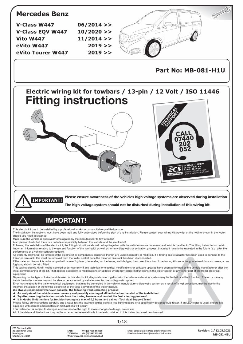
Part No: MB-081-H1U
1/18
www.ecs-electronicsuk.co.uk
Revision: 1 / 12.03.2021MB-081-H1U
ECS Electronics UK20 Speedwell Close Hun�ngtonChester, CH3 6DX
Email-sales: [email protected]: [email protected]
SALE: +44 (0) 7590 564639TECHNICAL: +44 (0) 7440 202052WEB: www.ecs-electronicsuk.co.uk
IMPORTANT!Please ensure awareness of the vehicles high voltage systems are observed during installation
The high voltage system should not be disturbed during installation of this wiring kit
Mercedes Benz
Electric wiring kit for towbars / 13-pin / 12 Volt / ISO 11446
06/2014 >>10/2020 >>11/2014 >>
2019 >>2019 >>
V-Class W447V-Class EQV W447Vito W447eVito W447eVito Tourer W447
2/18
Revision: 1 / 12.03.2021MB-081-H1U
ECS Electronics UK20 Speedwell Close Hun�ngtonChester, CH3 6DX
Email-sales: [email protected]: [email protected]
SALE: +44 (0) 7590 564639TECHNICAL: +44 (0) 7440 202052WEB: www.ecs-electronicsuk.co.uk
Part No: **-***-***
*/**
Electric wiring kit for towbars / **-pin / 12 Volt / ISO *****
This electric kit has to be installed by a professional workshop or a suitable qualified person.The installation instructions must have been read and fully understood before the start of any installation. Please contact your wiring kit provider or the hotline shown in the footer should you need assistance!Make sure the vehicle is approved/homologated by the manufacturer to tow a trailer! Also please check that there is a definite compatibility between this vehicle and the electric kit!Following the installation of the electric kit, the fitting instructions should be kept together with the vehicle service document and vehicle handbook. The fitting instructions contain important information relating to the use and function of the towing kit as well as for any diagnostic or activation process, that might have to be repeated in the future (e.g. after the performance of a vehicle software update).All warranty claims will be forfeited if the electric kit or components contained therein are used incorrectly or modified. If a towing socket adaptor has been used to connect to the trailer or bike rack, this must be removed from the trailer socket once the trailer or bike rack has been disconnected.If the trailer or bike rack is not equipped with a rear fog lamp, depending on the towing vehicle type, the correct function of the towing kit cannot be guaranteed. In such cases, a rear fog lamp should be retro fitted.This towing electric kit will not be covered under warranty if any technical or electrical modifications or software updates have been performed by the vehicle manufacturer after the initial commissioning of the kit. That applies especially to modifications or updates which may cause malfunctions in the trailer socket or any other part of the trailer electrical equipment!Depending on the type of trailer module used in this electric kit, diagnostic interrogation with the vehicle’s electrical system may be limited or will not function. The error memory inside the trailer module may not be able to be accessed by vehicle manufacturers diagnostic system.Error logs relating to the trailer electrical equipment, that may be generated in the vehicle manufacturers diagnostic system as a result of a test procedure, may be due to the incorrect installation of the towing electric kit or the false activation of the trailer module.We always recommend whenever possible, the following troubleshooting process: An analysis of the vehicle’s error memory and possibly clearing of all faults before the start of the installation! Try disconnecting the trailer module from the towing harness and re-start the fault clearing process! If in doubt, limit the time for troubleshooting to a max of 0,5 hours and call our Technical Support Team!Please follow our instructions carefully and always test the towing electrics using a true lighting board or a specifically designed bulb tester. If an LED tester is used, ensure it is equipped with correct load resistors or malfunctions will occur! This instruction is subject to changes and we reserve the right to make changes to design, colour etc. All of the data and illustrations may not be an exact representation but the text contained in this instruction must be observed!
******** **/**** >>
************
www.ecs-electronicsuk.co.uk
Revision: * / **.**.******-***-***
ECS Electronics UK20 Speedwell Close Hun�ngtonChester, CH3 6DX
Email-sales: [email protected]: [email protected]
SALE: +44 (0) 7590 564639TECHNICAL: +44 (0) 7440 202052WEB: www.ecs-electronicsuk.co.uk
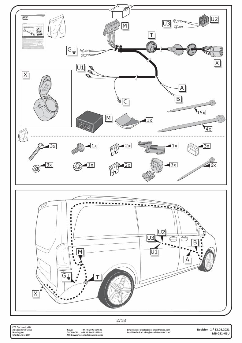
X
G
M
T
A
BU1
U2U3
M
G
X
T
A
BC
U1
U3U2
X
4x
15x1xM
3x
3x
1x
6x1x 20 Amp. 2x
15 Amp. 2x
3x
1x 3x
3/18
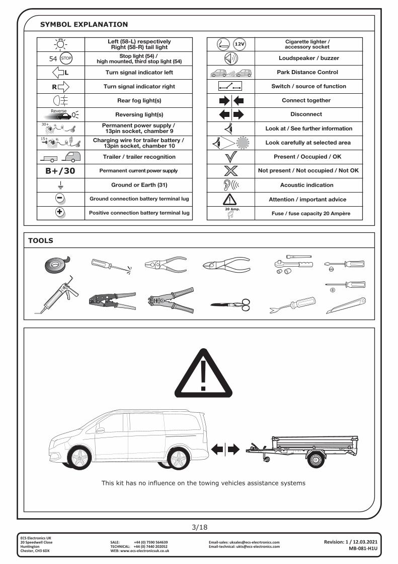
SYMBOL EXPLANATION
TOOLS
Left (58-L) respectivelyRight (58-R) tail light
Stop light (54) / high mounted, third stop light (54)
Turn signal indicator left
Turn signal indicator right
Rear fog light(s)
Reversing light(s)
Trailer / trailer recognition
Permanent current power supply
Ground or Earth (31)
Ground connection battery terminal lug
Permanent power supply / 13pin socket, chamber 9
Charging wire for trailer battery / 13pin socket, chamber 10
+
15+
+
30+
Positive connection battery terminal lug
54 STOP
L
R
Reverse
B+/30
Fuse / fuse capacity 20 Ampère
Cigarette lighter /accessory socket
Loudspeaker / buzzer
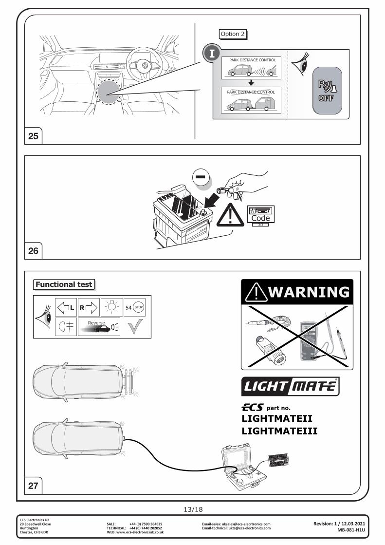
Park Distance Control
Switch / source of function
Connect together
Disconnect
Look at / See further information
Look carefully at selected area
Present / Occupied / OK
Not present / Not occupied / Not OK
Acoustic indication
Attention / important advice
20 Amp.
20 Amp.
12V
Revision: 1 / 12.03.2021MB-081-H1U
ECS Electronics UK20 Speedwell Close Hun�ngtonChester, CH3 6DX
Email-sales: [email protected]: [email protected]
SALE: +44 (0) 7590 564639TECHNICAL: +44 (0) 7440 202052WEB: www.ecs-electronicsuk.co.uk
This kit has no influence on the towing vehicles assistance systems
4/18
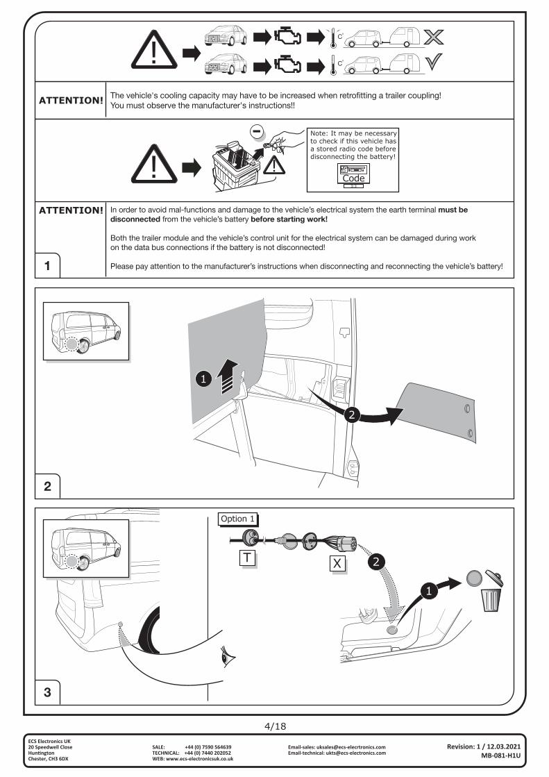
ATTENTION! In order to avoid mal-functions and damage to the vehicle’s electrical system the earth terminal must be disconnected from the vehicle’s battery before starting work!
Both the trailer module and the vehicle’s control unit for the electrical system can be damaged during workon the data bus connections if the battery is not disconnected!
Please pay attention to the manufacturer’s instructions when disconnecting and reconnecting the vehicle’s battery!
!Code
3:3
Note: It may be necessaryto check if this vehicle hasa stored radio code beforedisconnecting the battery!
Co
Co
1
3
2
ATTENTION! The vehicle's cooling capacity may have to be increased when retrofitting a trailer coupling!You must observe the manufacturer's instructions!!
Revision: 1 / 12.03.2021MB-081-H1U
ECS Electronics UK20 Speedwell Close Hun�ngtonChester, CH3 6DX
Email-sales: [email protected]: [email protected]
SALE: +44 (0) 7590 564639TECHNICAL: +44 (0) 7440 202052WEB: www.ecs-electronicsuk.co.uk
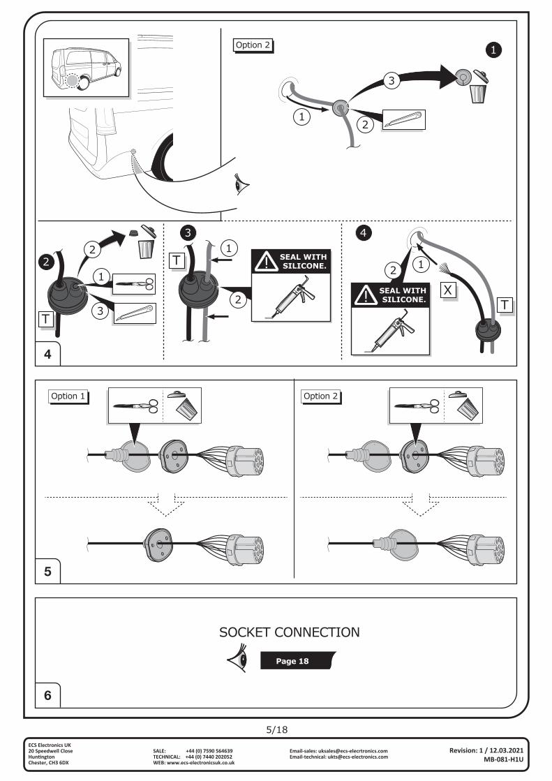
1
2
XT
1
2
Option 1
5/18
4
6
5
Revision: 1 / 12.03.2021MB-081-H1U
ECS Electronics UK20 Speedwell Close Hun�ngtonChester, CH3 6DX
Email-sales: [email protected]: [email protected]
SALE: +44 (0) 7590 564639TECHNICAL: +44 (0) 7440 202052WEB: www.ecs-electronicsuk.co.uk
Option 2
12
3
1
2
3
T SEAL WITH SILICONE.
1
2
1
3 4
TXSEAL WITH
SILICONE.
12
Page 18
SOCKET CONNECTION
T
2
Option 1 Option 2
6/18
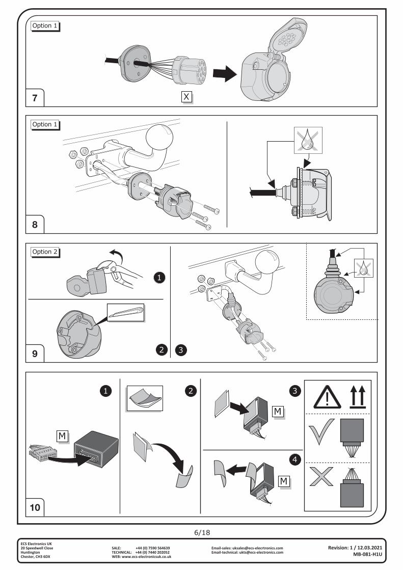
10
Revision: 1 / 12.03.2021MB-081-H1U
ECS Electronics UK20 Speedwell Close Hun�ngtonChester, CH3 6DX
Email-sales: [email protected]: [email protected]
SALE: +44 (0) 7590 564639TECHNICAL: +44 (0) 7440 202052WEB: www.ecs-electronicsuk.co.uk
7
9
8
M
M
M
1 2 3
4
Option 1
X
Option 1
1
2 3
Option 2
7/18
Revision: 1 / 12.03.2021MB-081-H1U
ECS Electronics UK20 Speedwell Close Hun�ngtonChester, CH3 6DX
Email-sales: [email protected]: [email protected]
SALE: +44 (0) 7590 564639TECHNICAL: +44 (0) 7440 202052WEB: www.ecs-electronicsuk.co.uk
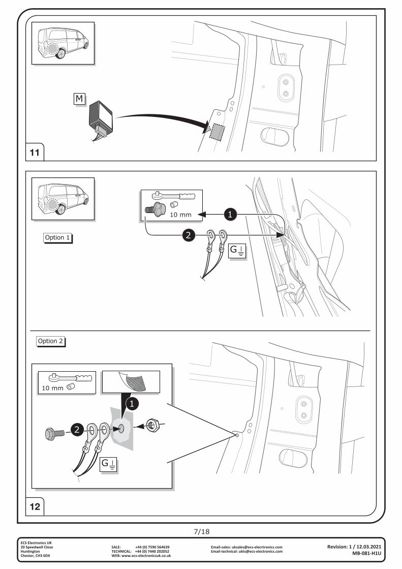
12
11
M
10 mm 1
G2Option 1
Option 2
10 mm
G
1
2
8/18
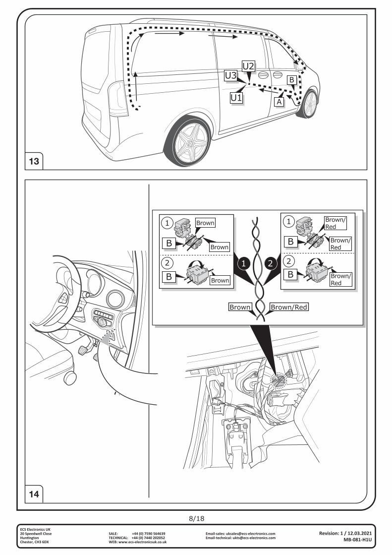
13
14
Revision: 1 / 12.03.2021MB-081-H1U
ECS Electronics UK20 Speedwell Close Hun�ngtonChester, CH3 6DX
Email-sales: [email protected]: [email protected]
SALE: +44 (0) 7590 564639TECHNICAL: +44 (0) 7440 202052WEB: www.ecs-electronicsuk.co.uk
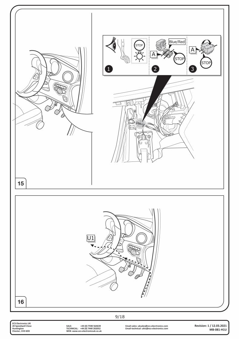
A
B
U1
U2U3
Brown Brown/Red
1
2
B
Brown/Red
Brown/Red
B Brown/Red
1
2
B
Brown
Brown
B Brown
1 2
9/18
15
16
Revision: 1 / 12.03.2021MB-081-H1U
ECS Electronics UK20 Speedwell Close Hun�ngtonChester, CH3 6DX
Email-sales: [email protected]: [email protected]
SALE: +44 (0) 7590 564639TECHNICAL: +44 (0) 7440 202052WEB: www.ecs-electronicsuk.co.uk
STOP
A
Blue/Red
ASTOP
STOP
1 2 3
U1
10/18
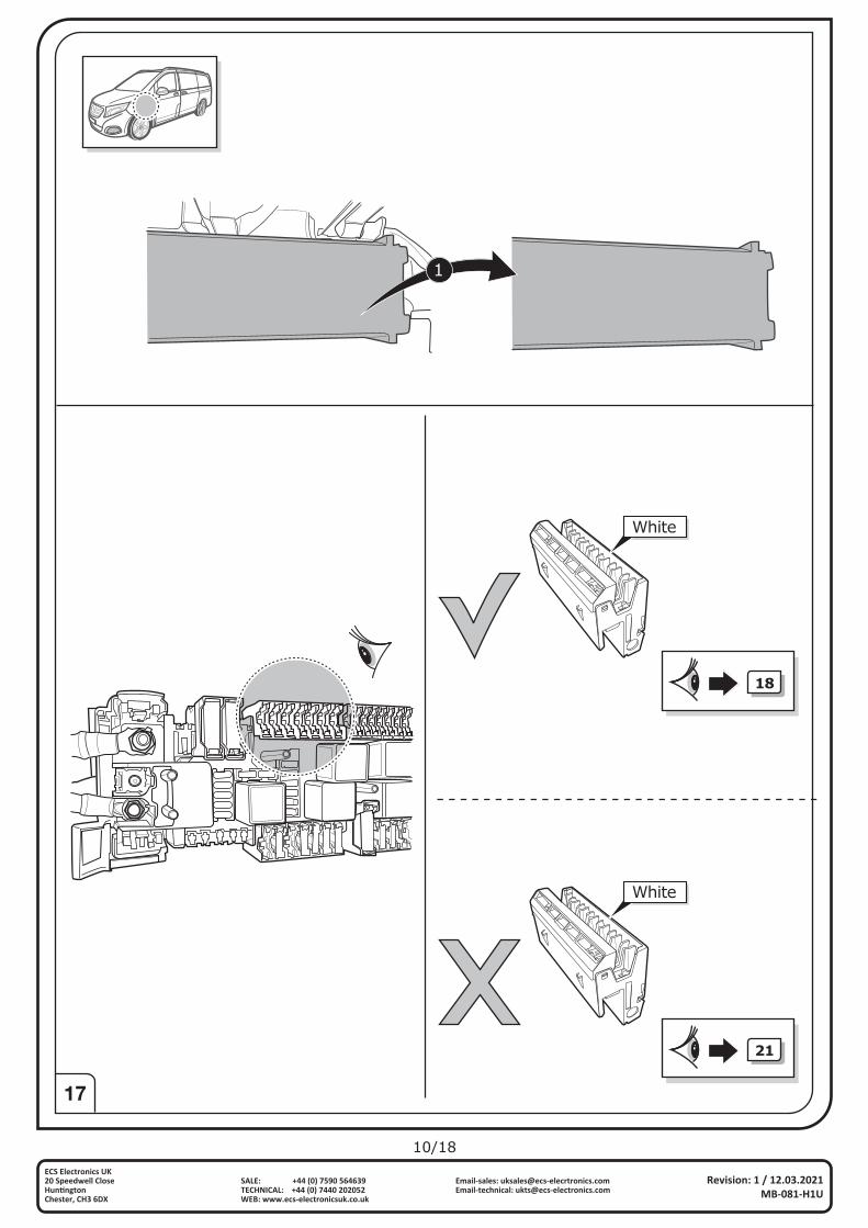
17
Revision: 1 / 12.03.2021MB-081-H1U
ECS Electronics UK20 Speedwell Close Hun�ngtonChester, CH3 6DX
Email-sales: [email protected]: [email protected]
SALE: +44 (0) 7590 564639TECHNICAL: +44 (0) 7440 202052WEB: www.ecs-electronicsuk.co.uk
1
White
White
18
21
11/18
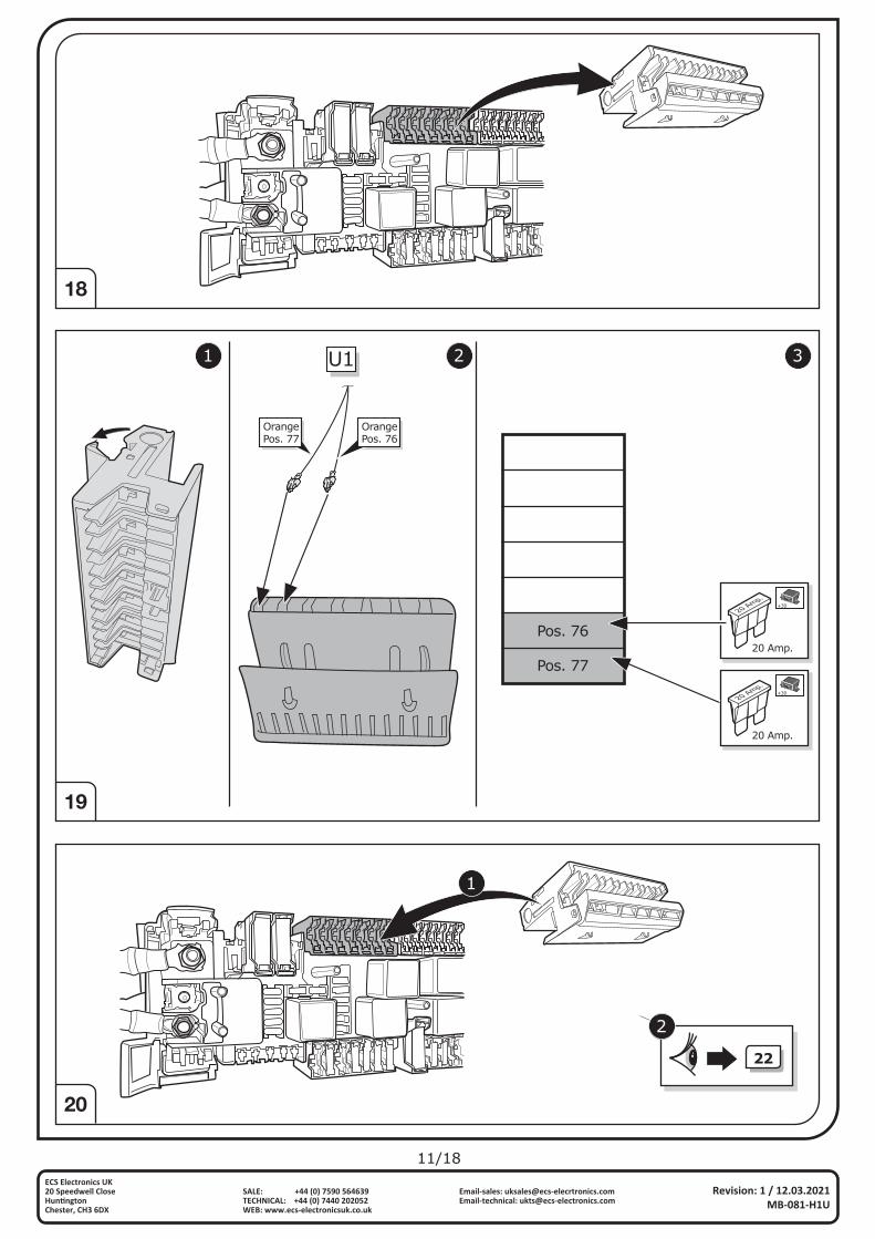
18
20
19
Revision: 1 / 12.03.2021MB-081-H1U
ECS Electronics UK20 Speedwell Close Hun�ngtonChester, CH3 6DX
Email-sales: [email protected]: [email protected]
SALE: +44 (0) 7590 564639TECHNICAL: +44 (0) 7440 202052WEB: www.ecs-electronicsuk.co.uk
1 2 3U1
OrangePos. 76
OrangePos. 77
Pos. 76
Pos. 77
20 Amp.
20 Amp.
+30
20 Amp.
20 Amp.
+30
1
22
2
12/18
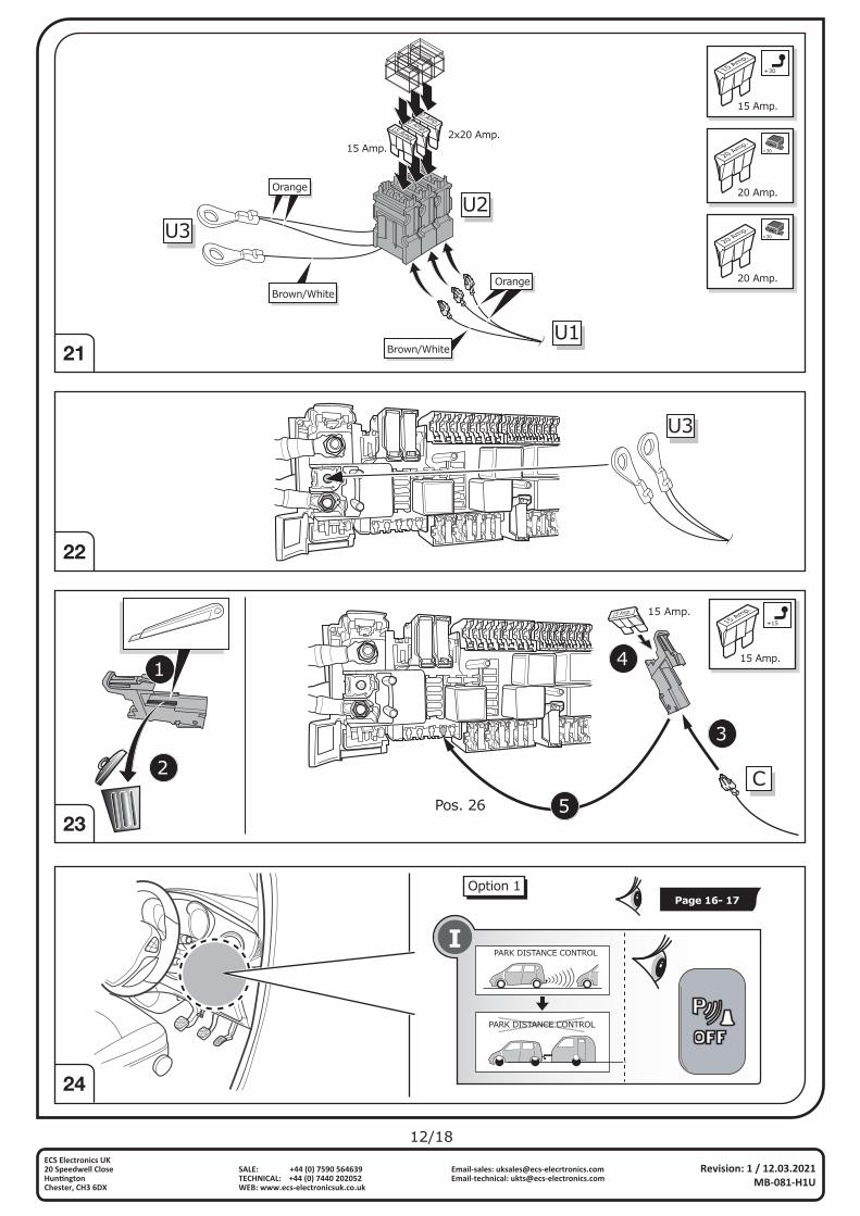
21
24
Revision: 1 / 12.03.2021MB-081-H1U
ECS Electronics UK20 Speedwell Close Hun�ngtonChester, CH3 6DX
Email-sales: [email protected]: [email protected]
SALE: +44 (0) 7590 564639TECHNICAL: +44 (0) 7440 202052WEB: www.ecs-electronicsuk.co.uk
23
22
Option 1
PARK DISTANCE CONTROL
PARK DISTANCE CONTROL
Page 16- 17
Orange
OrangeBrown/White
Brown/WhiteU1
U2U3
2x20 Amp.15 Amp.
15 Amp.
20 Amp.
20 Amp.
15 Amp.
15 Amp.
+30
20 Amp.
20 Amp.
+30
20 Amp.
20 Amp.
+30
U3
C
15 Amp.
3
4
5
15 Amp.
Pos. 26
15 Amp.
15 Amp.
+15
1
2
13/18
Revision: 1 / 12.03.2021MB-081-H1U
ECS Electronics UK20 Speedwell Close Hun�ngtonChester, CH3 6DX
Email-sales: [email protected]: [email protected]
SALE: +44 (0) 7590 564639TECHNICAL: +44 (0) 7440 202052WEB: www.ecs-electronicsuk.co.uk
25
27
! Code3:3
26
WARNING
OFF
VHz
Hz
Hz
Hz
A
V
COM10A
400mA
mA
V
mV
HOLD MINMAX RANGE
DC
Manual Range 60+
V
Functional test
L 54 STOPR
Reverse
part no.
LIGHTMATEIILIGHTMATEIII
Option 2
PARK DISTANCE CONTROL
PARK DISTANCE CONTROL
14/18
Revision: 1 / 12.03.2021MB-081-H1U
ECS Electronics UK20 Speedwell Close Hun�ngtonChester, CH3 6DX
Email-sales: [email protected]: [email protected]
SALE: +44 (0) 7590 564639TECHNICAL: +44 (0) 7440 202052WEB: www.ecs-electronicsuk.co.uk
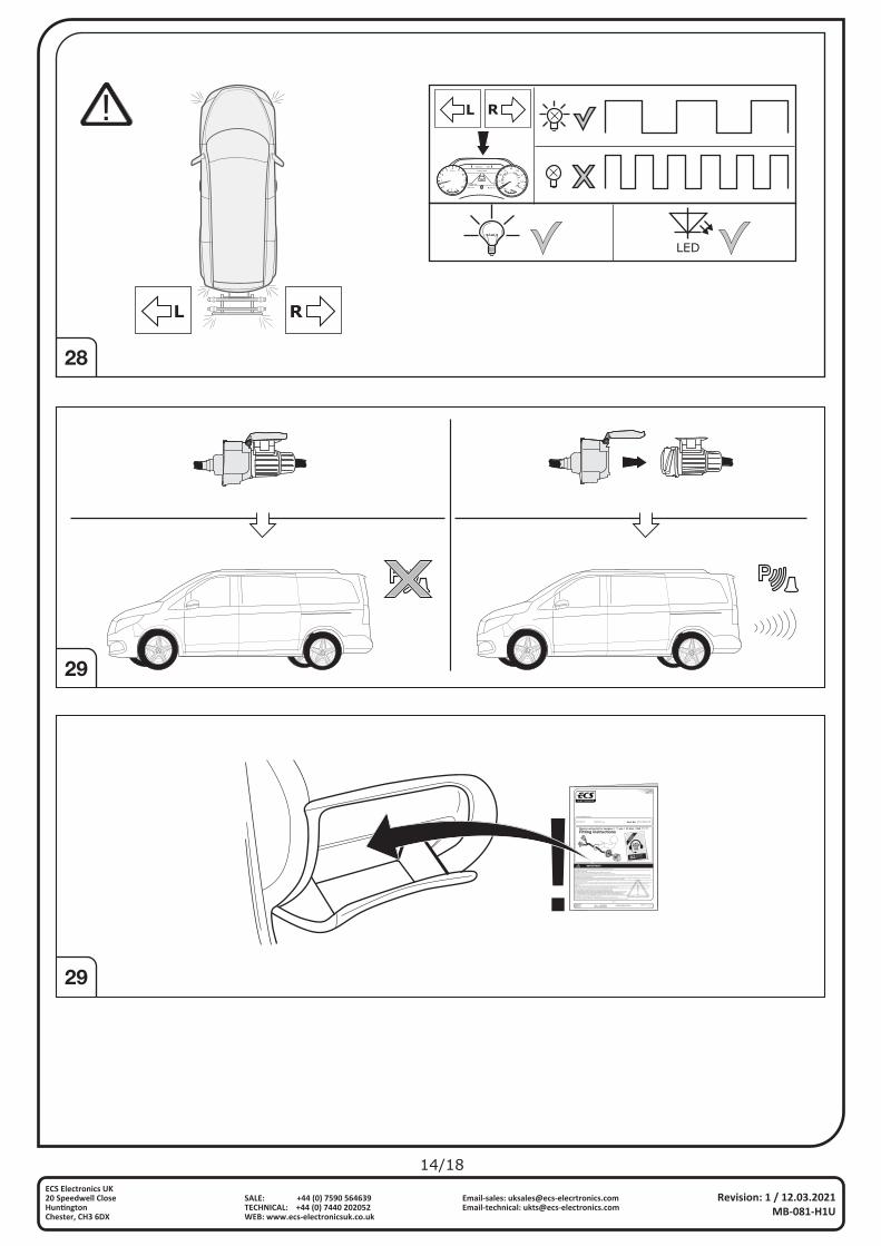
28
29
29
Part No: **-***-***
*/**
Electric wiring kit for towbars / **-pin / 12 Volt / ISO *****
This electric kit has to be installed by a professional workshop or a suitable qualified person.The installation instructions must have been read and fully understood before the start of any installation. Please contact your wiring kit provider or the hotline shown in the footer should you need assistance!Make sure the vehicle is approved/homologated by the manufacturer to tow a trailer! Also please check that there is a definite compatibility between this vehicle and the electric kit!Following the installation of the electric kit, the fitting instructions should be kept together with the vehicle service document and vehicle handbook. The fitting instructions contain important information relating to the use and function of the towing kit as well as for any diagnostic or activation process, that might have to be repeated in the future (e.g. after the performance of a vehicle software update).All warranty claims will be forfeited if the electric kit or components contained therein are used incorrectly or modified. If a towing socket adaptor has been used to connect to the trailer or bike rack, this must be removed from the trailer socket once the trailer or bike rack has been disconnected.If the trailer or bike rack is not equipped with a rear fog lamp, depending on the towing vehicle type, the correct function of the towing kit cannot be guaranteed. In such cases, a rear fog lamp should be retro fitted.This towing electric kit will not be covered under warranty if any technical or electrical modifications or software updates have been performed by the vehicle manufacturer after the initial commissioning of the kit. That applies especially to modifications or updates which may cause malfunctions in the trailer socket or any other part of the trailer electrical equipment!Depending on the type of trailer module used in this electric kit, diagnostic interrogation with the vehicle’s electrical system may be limited or will not function. The error memory inside the trailer module may not be able to be accessed by vehicle manufacturers diagnostic system.Error logs relating to the trailer electrical equipment, that may be generated in the vehicle manufacturers diagnostic system as a result of a test procedure, may be due to the incorrect installation of the towing electric kit or the false activation of the trailer module.We always recommend whenever possible, the following troubleshooting process: An analysis of the vehicle’s error memory and possibly clearing of all faults before the start of the installation! Try disconnecting the trailer module from the towing harness and re-start the fault clearing process! If in doubt, limit the time for troubleshooting to a max of 0,5 hours and call our Technical Support Team!Please follow our instructions carefully and always test the towing electrics using a true lighting board or a specifically designed bulb tester. If an LED tester is used, ensure it is equipped with correct load resistors or malfunctions will occur! This instruction is subject to changes and we reserve the right to make changes to design, colour etc. All of the data and illustrations may not be an exact representation but the text contained in this instruction must be observed!
******** **/**** >>
************
www.ecs-electronicsuk.co.uk
Revision: * / **.**.******-***-***
ECS Electronics UK20 Speedwell Close Hun�ngtonChester, CH3 6DX
Email-sales: [email protected]: [email protected]
SALE: +44 (0) 7590 564639TECHNICAL: +44 (0) 7440 202052WEB: www.ecs-electronicsuk.co.uk
!
MENUOK
P 500 miles6666 miles
Driving Aids
6:00 AM 36 F
C H0
1
23 4
56
7
8
RPMx1000
1/210
20
40
6080
100
120
140
160
20
40
60
80100
120 140160
180
200
220
240
260km/h
LED
RL
L R
15/18
Revision: 1 / 12.03.2021MB-081-H1U
ECS Electronics UK20 Speedwell Close Hun�ngtonChester, CH3 6DX
Email-sales: [email protected]: [email protected]
SALE: +44 (0) 7590 564639TECHNICAL: +44 (0) 7440 202052WEB: www.ecs-electronicsuk.co.uk
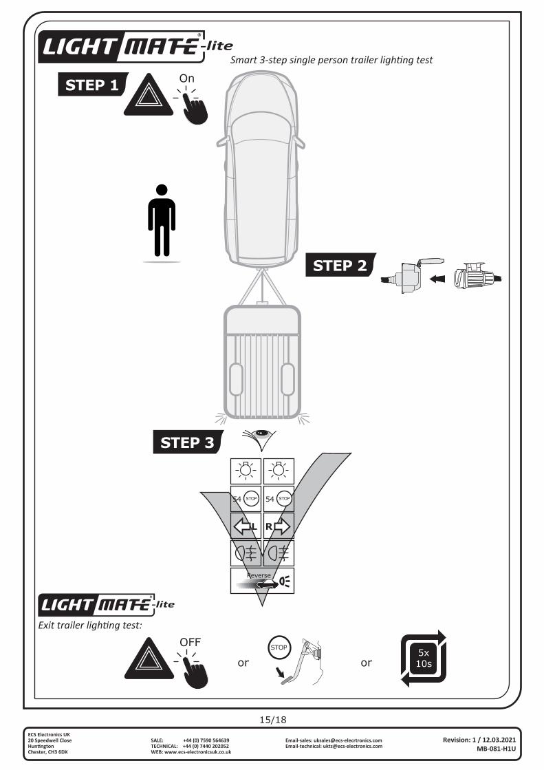
Smart 3-step single person trailer lighting test-lite
-lite
OnSTEP 1
STEP 2
STEP 3
L
54 STOP 54 STOP
R
Reverse
Exit trailer lighting test:
OFF
or orSTOP
5x10s

16/18
Revision: 1 / 12.03.2021MB-081-H1U
ECS Electronics UK20 Speedwell Close Hun�ngtonChester, CH3 6DX
Email-sales: [email protected]: [email protected]
SALE: +44 (0) 7590 564639TECHNICAL: +44 (0) 7440 202052WEB: www.ecs-electronicsuk.co.uk
Mercedes
DE GB FR
Die Aktivierung der Anhängerfunktionenmuss wie folgt durchgeführt werden:
1. Computer mit Auto verbinden 2. Programm starten 3. Klicke auf „Sonderfunktionen“ 4. Klicke auf “Eingabe bei Nachrüstungen
oder Umbauten“ 5. Gebe Benutzername und Passwort ein 6. Schreibe Q50 beim oberen (+) Feld und E57 beim unteren (-) Feld ein 7. Akzeptiere und beende das Programm. 8. Starte Programm erneut 9. Klicke auf „Steuergeräte Ansicht“
10. Verbaute Steuergeräte wie folgt programmieren:
a. Klicke z.B. auf „EZS” (Elektronisches Zündschloss)
b. Klicke auf „Anpassung“ c. Auf der linken Seite:
Klicke auf Aktualisierung SCN-Codierung d. Gehe online und warte ein paar Sekunden
11. Vorgang mit allen unten aufgeführten Steuergeräten durchführen:
- „EZS” (Elektronisches Zündschloss) - “SAM” (Signalerfass- und Ansteuermodul)
- “ESP” (Elektronisches Stabilitätsprogramm)
Wenn verbaut:
- “Kombiinstrument”
- “Headunit/Audio 20”
- “Parksystem” - “360°-Kamera”
Ende der Codierung
The activation of the trailer functionshas to be carried as follows:
1. Connect computer to car 2. Start program 3. Click "Special functions" 4. Click "Input for retrofits or conversions" 5. Enter you user name and password 6. Write Q50 in the upper (+) field and E57 in the lower (-) field 7. Accept and close the program. 8. Start the program again 9. Click "Controllers View"
10. code installed control units as follows:
a. Click e.g. "EZS" (Ignition) b. Click "Adjust" c. On the left side: click updating SCN encoding d. Go online a wait a few seconds
11. Perform the operation with all the control units listed below: - "EZS" (Ignition)
- "ESP" (Electronic Stability Program)
- "SAM" (Signal detection- and control modul)
- "combined instrument"
- "headunit/Audio 20"
if fitted:
- “Parksystem” - "360° camera" Coding finished
L’activationdes functionsde la remorquedoit être effectuée comme suit:
1. Relier l’ordinateur à la voiture 2. Démarrer le programme 3. Cliquez sur «Fonctions spéciales» 4. Cliquez sur «Saisie pour rééquipement ou transformation» 5. Saisissez le nom d’utilisateur et le mot de passe 6. Inscrivez Q50 dans la zone(+) en haut et E57 dans la zone (-) en bas
7. Acceptez et quittez le programme 8. Redémarrez le programme 9. Cliquez sur «Vue appareils de commande»
10. Programmez des appareils de commande montés comme suit:
a. Cliquez p. ex. sur «EZS» (Allumage) b. Cliquez sur «Adaptation» c. Sur le côté gauche: Cliquez sur actualisation SCN Codage d. Rendez-vous en ligne et attendez quelques secondes
11. Effectuer la procédure avec toutes les unités de commande dans la liste ci-dessous:
- «EZS» (Allumage)
- «SAM» (Module de Commande)
- “ESP” (régulation du comportement dynamique)
- «instrument combiné»
- «headunit/Audio 20»
si installé:
- «Système de stationnement»- «Caméra panoramique»
Fin de codage
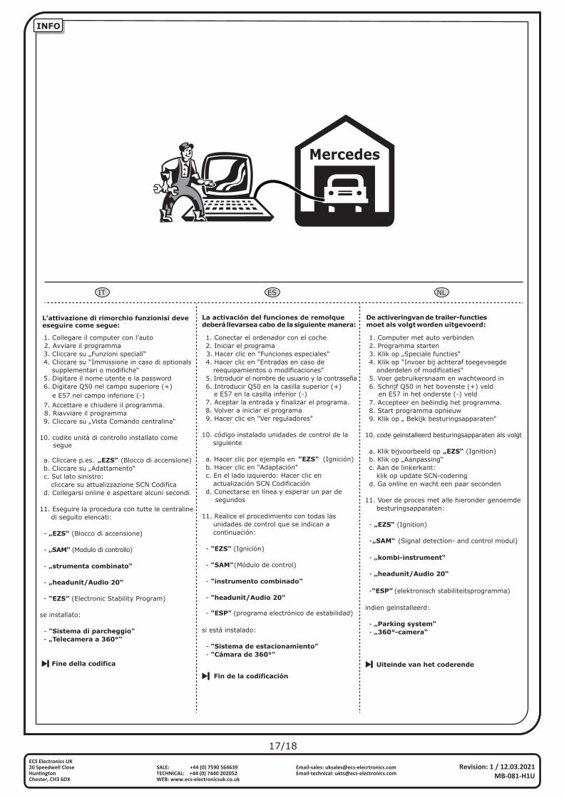
INFO
Revision: 1 / 12.03.2021MB-081-H1U
ECS Electronics UK20 Speedwell Close Hun�ngtonChester, CH3 6DX
Email-sales: [email protected]: [email protected]
SALE: +44 (0) 7590 564639TECHNICAL: +44 (0) 7440 202052WEB: www.ecs-electronicsuk.co.uk
17/18
INFO
Mercedes
IT ES NL
1. Collegare il computer con l’auto 2. Avviare il programma 3. Cliccare su „Funzioni speciali“ 4. Cliccare su “Immissione in caso di optionals supplementari o modifiche“ 5. Digitare il nome utente e la password 6. Digitare Q50 nel campo superiore (+) e E57 nel campo inferiore (-)
1. Conectar el ordenador con el coche 2. Iniciar el programa 3. Hacer clic en "Funciones especiales" 4. Hacer clic en "Entradas en caso de reequipamientos o modificaciones" 5. Introducir el nombre de usuario y la contraseña 6. Introducir Q50 en la casilla superior (+) e E57 en la casilla inferior (-)
1. Computer met auto verbinden 2. Programma starten 3. Klik op „Speciale functies“ 4. Klik op “Invoer bij achteraf toegevoegde onderdelen of modificaties“ 5. Voer gebruikersnaam en wachtwoord in 6. Schrijf Q50 in het bovenste (+) veld en E57 in het onderste (-) veld
La activación del funciones de remolquedeberállevarsea cabo de lasiguiente manera:
De activeringvande trailer-functiesmoet als volgtworden uitgevoerd:
L’attivazione di rimorchio funzionisi deveeseguire come segue:
7. Accettare e chiudere il programma. 8. Riavviare il programma 9. Cliccare su „Vista Comando centralina“
10. codite unità di controllo installato come segue
a. Cliccare p.es. „EZS“ (Blocco di accensione) b. Cliccare su „Adattamento“ c. Sul lato sinistro: cliccare su attualizzazione SCN Codifica d. Collegarsi online e aspettare alcuni secondi
11. Eseguire la procedura con tutte le centraline di seguito elencati:
- „EZS“ (Blocco di accensione)
- “EZS” (Electronic Stability Program)
- „SAM“ (Modulo di controllo)
- „strumenta combinato“
- „headunit/Audio 20“
se installato:
- "Sistema di parcheggio" - „Telecamera a 360°“
Fine della codifica
7. Aceptar la entrada y finalizar el programa. 8. Volver a iniciar el programa 9. Hacer clic en "Ver reguladores"
10. código instalado unidades de control de la siguiente
a. Hacer clic por ejemplo en "EZS" (Ignición) b. Hacer clic en "Adaptación" c. En el lado izquierdo: Hacer clic en actualización SCN Codificación d. Conectarse en línea y esperar un par de segundos
11. Realice el procedimiento con todas las unidades de control que se indican a continuación:
- "EZS" (Ignición)
- "ESP" (programa electrónico de estabilidad)
- "SAM" (Módulo de control)
- "instrumento combinado"
- "headunit/Audio 20"
si está instalado:
- "Sistema de estacionamiento" - "Cámara de 360°"
Fin de la codificación
7. Accepteer en beëindig het programma. 8. Start programma opnieuw 9. Klik op „ Bekijk besturingsapparaten“
10. code geïnstalleerd besturingsapparaten als volgt
a. Klik bijvoorbeeld op „EZS“ (Ignition) b. Klik op „Aanpassing“ c. Aan de linkerkant: klik op update SCN-codering d. Ga online en wacht een paar seconden
11. Voer de proces met alle hieronder genoemde besturingsapparaten:
- „EZS“ (Ignition)
- „SAM“ (Signal detection- and control modul)
(elektronisch stabiliteitsprogramma)
- „kombi-instrument“
- „headunit/Audio 20“
-“ESP”
indien geïnstalleerd:
- „Parking system“ - „360°-camera“
Uiteinde van het coderende
Revision: 1 / 12.03.2021MB-081-H1U
ECS Electronics UK20 Speedwell Close Hun�ngtonChester, CH3 6DX
Email-sales: [email protected]: [email protected]
SALE: +44 (0) 7590 564639TECHNICAL: +44 (0) 7440 202052WEB: www.ecs-electronicsuk.co.uk
18/18
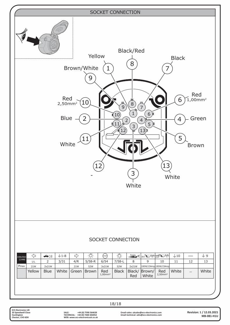
SOCKET CONNECTION
SOCKET CONNECTION
1
12 135
67
89
10
112
342 4
87
6
312
11
1
10
9
5
13
WhiteWhite
Brown
-
Red1,00mm2Red
2,50mm2
Yellow
Blue Green
BlackBlack/Red
Brown/White
White
1-8 STOPReverse +
-15 amp.
30++
-15 amp.
15+ 10 9
2x21W21W 21W 52W 3x21W 52W 2x21W 180W/15Amp 180W/15Amp
DIN/ISO 11446
Pmax
Yellow Blue White Green Brown Red1,00mm² 2,50mm²
Black Black/Red
Brown/White
Red White _ White
1/L 2 3/31 4/R 5/58-R 6/54 7/58-L 8 9 10 11 12 13