Embed Size (px)
Citation preview
8/8/2019 Merc Manual v5
http://slidepdf.com/reader/full/merc-manual-v5 1/76
SCANTOOL
The fastest and easiest way to troubleshoot Marine Electronic Fuel Injection Systems
USER’S GUIDE
Rinda Technologies, Inc.
Version 5
MerCruiser

8/8/2019 Merc Manual v5
http://slidepdf.com/reader/full/merc-manual-v5 2/76

8/8/2019 Merc Manual v5
http://slidepdf.com/reader/full/merc-manual-v5 3/76
MerCruiser
SCANTOOL
USER’S GUIDE
Rinda Technologies Inc.4563 N. Elston Ave.
Chicago, IL 60630 USA
Tel: (773) 736-6633Fax: (773) 736-2950
Web: www.rinda.com
Serial Number: ________________________________

8/8/2019 Merc Manual v5
http://slidepdf.com/reader/full/merc-manual-v5 4/76
Limited Warranty
To the original purchaser only, Rinda Technologies, Inc. warrants the supplied scan tool hardware to befree from defects in materials and workmanship under normal use for a period of 1 year from date of
purchase as evidenced by a copy of the sales receipt. Rinda Technologies, Inc. makes no other expresswarranties on the hardware products. The purchaser’s sole remedy in the event of a breach of warranty isexpressly limited to repair of the defective scan tool hardware. Repair parts and replacement hardware
products will be provided on an exchange basis and will be either reconditioned or new. All replaced parts become property of Rinda Technologies, Inc. This limited warranty does not cover damage to the productsresulting frommisuse, accident, disaster, abuse, negligence, improper maintenance, or modification and/or repair of the hardware product other than by Rinda Technologies, Inc.
The software components in the scan tool are believed to be accurate. Rinda Technologies, Inc. does notwarrant that the operation of the software will be uninterrupted or error free. Further, Rinda Technologies,Inc. does not warrant or guarantee the use of, or the results of the use of, the software in terms of correctness,accuracy, reliability, currentness, or otherwise.
Limitation of Liability
Neither Rinda Technologies, Inc. nor its authorized dealershall be liable for any defect, indirect, incidental,special, or consequential damages, whether in an action in contract or tort (including negligence and strictliability), such as, but not limited to, loss of anticipated profits or benefits resulting from the use of this scantool and its software or any breach of any warranty, even if Rinda Technologies or its authorized dealer has
been advised of the possibility of such damages. In no event will Rinda Technologies, Inc. or its authorizeddealer’s liability exceed the price paid for the product.
The information presented in this manual is believed to be accurate. Responsibility for errors, omission of information, or consequences resulting from the use of this information cannot be assumed by RindaTechnologies, Inc. Rinda Technologies, Inc. retains all rights to make changes to specifications at any timewithout notice.
Reproduction of this manual, in whole or in part, is forbiddenwithout the express written permission of Rinda Technologies Inc.Manual contents including photographs Copyright ©) 1997-2008 Rinda Technologies Inc.All rights reserved worldwide.
Volvo Penta is a registered trademark of Volvo Penta Corp. MerCruiser, Thunderbolt V, D-Tronic andMercury are registered trademarks of Brunswick Corp. GM is a registered trademark of General MotorsCorp. Indmar is a registered trademark of Indmar Engine Co. Pleasurecraft and Crusader are registeredtrademarks of Pleasurecraft Engine Group. All other trademarks are properties of their respective holders.
8/8/2019 Merc Manual v5
http://slidepdf.com/reader/full/merc-manual-v5 5/76
Table of Contents
Safety Precautions . . . . . . . . . . . . . . . . . . . . . 2
Overview . . . . . . . . . . . . . . . . . . . . . . . . . . . 3
Scan Tool Key Functions . . . . . . . . . . . . . . . . . . 4
Setup & Operation. . . . . . . . . . . . . . . . . . . . . . 5
Function Flowchart . . . . . . . . . . . . . . . . . . . . . 6
Marine Engines Supported by the Scan Tool . . . . . . . 9
Engines with GM MEFI . . . . . . . . . . . . . . . . . 12
Volvo Penta EGC EFI . . . . . . . . . . . . . . . . . 25
Pleasurecraft / Crusader ECM-07 & ECM-08 . . . . . 32
Indmar GCP EFI . . . . . . . . . . . . . . . . . . . . 33
OBD-M compliant EFI . . . . . . . . . . . . . . . . . 34
MerCruiser PCM-555 / ECM-555 EFI . . . . . . . . . 35
MerCruiser PCM-09 (Visteon) EFI . . . . . . . . . . . 49
MerCruiser Thunderbolt V Ignition . . . . . . . . . . 50
MerCruiser 2.8L / 4.2L D-Tronic Diesel . . . . . . . 58
MerCruiser 7.3L D-Tronic Diesel . . . . . . . . . . . 59
Mercury 3.0L Carbureted Outboard. . . . . . . . . . 60
Mercury 3.0L EFI Outboard . . . . . . . . . . . . . . 62
Mercury Hi Perf 2.0 / 2.5 L EFI Outboard . . . . . . . 63
Injector Test Mode . . . . . . . . . . . . . . . . . . . . . 64
Support Information. . . . . . . . . . . . . . . . . . . . . 66
Scan Tool Adapters . . . . . . . . . . . . . . . . . . . . . 67
Page 1
8/8/2019 Merc Manual v5
http://slidepdf.com/reader/full/merc-manual-v5 6/76
Safety Precautions
Before attempting to use the MerCruiser Scan Tool pleaseread and observe the following safety precautions:
· Always refer to and follow the engine and boat manufacturer’s safetyand service procedures to prevent personal injury and equipmentdamage.
· Never connect or disconnect the scan tool with the vehicle’s ignitionturned ON or while the engine is running.
· Always stay clear of any moving or movable engine componentswhen connecting and using the scan tool.
· When working near marine batteries never use any device that iscapable of producing a spark, high temperature or open flame.Marine batteries contain sulfuric acid and produce highly explosivegasses that may ignite. To prevent serious injury always observe this
precaution along with the safety precautions provided by the engine, boat and battery manufacturers.
· Always test and service a running engine in a well ventilated area.
· Always wear approved eye protection.
IMPORTANT
· This scan tool is a sensitive electronic instrument. Handle the toolwith extreme care.
· DO NOT subject the scan tool to excessive water spray or expose it
to rain. The scan tool is water resistant but not water proof.· DO NOT leave the scan tool in direct sunlight for extended periods of
time or subject it to extreme temperatures (hot or cold).
· ALWAYS store the scan tool in its protective carrying case (# 94015)when not in use. If you do not have a carrying case, store the scanner in its original packaging.
Page 2
8/8/2019 Merc Manual v5
http://slidepdf.com/reader/full/merc-manual-v5 7/76
Overview
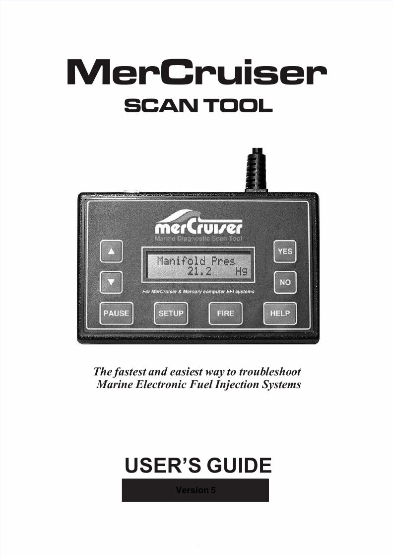
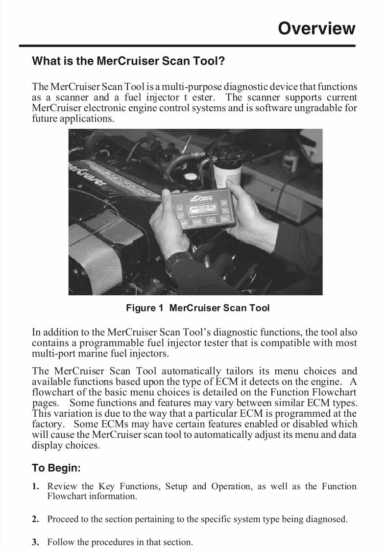
What is the MerCruiser Scan Tool?
The MerCruiser Scan Tool is a multi-purpose diagnostic device that functions
as a scanner and a fuel injector t ester. The scanner supports currentMerCruiser electronic engine control systems and is software ungradable for future applications.
In addition to the MerCruiser Scan Tool’s diagnostic functions, the tool alsocontains a programmable fuel injector tester that is compatible with mostmulti-port marine fuel injectors.
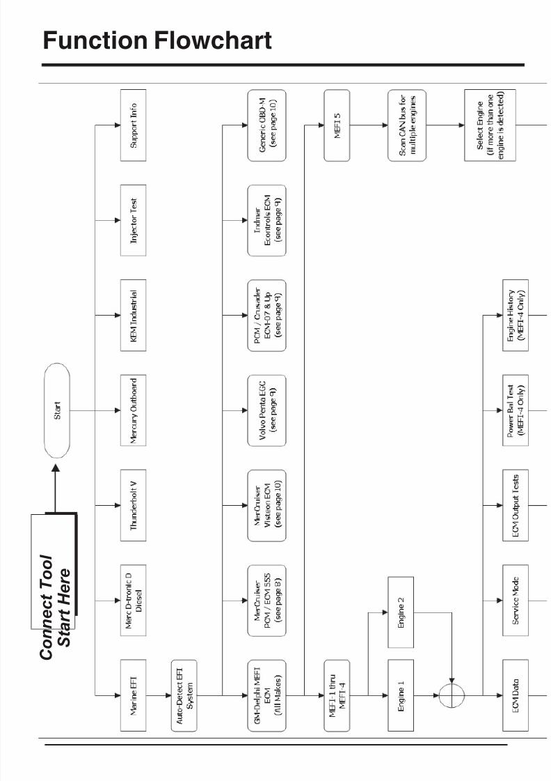
The MerCruiser Scan Tool automatically tailors its menu choices and
available functions based upon the type of ECM it detects on the engine. Aflowchart of the basic menu choices is detailed on the Function Flowchart pages. Some functions and features may vary between similar ECM types.This variation is due to the way that a particular ECM is programmed at thefactory. Some ECMs may have certain features enabled or disabled whichwill cause the MerCruiser scan tool to automatically adjust its menu and datadisplay choices.
To Begin:
1. Review the Key Functions, Setup and Operation, as well as the FunctionFlowchart information.
2. Proceed to the section pertaining to the specific system type being diagnosed.
3. Follow the procedures in that section.
Page 3
Figure 1 MerCruiser Scan Tool
8/8/2019 Merc Manual v5
http://slidepdf.com/reader/full/merc-manual-v5 8/76
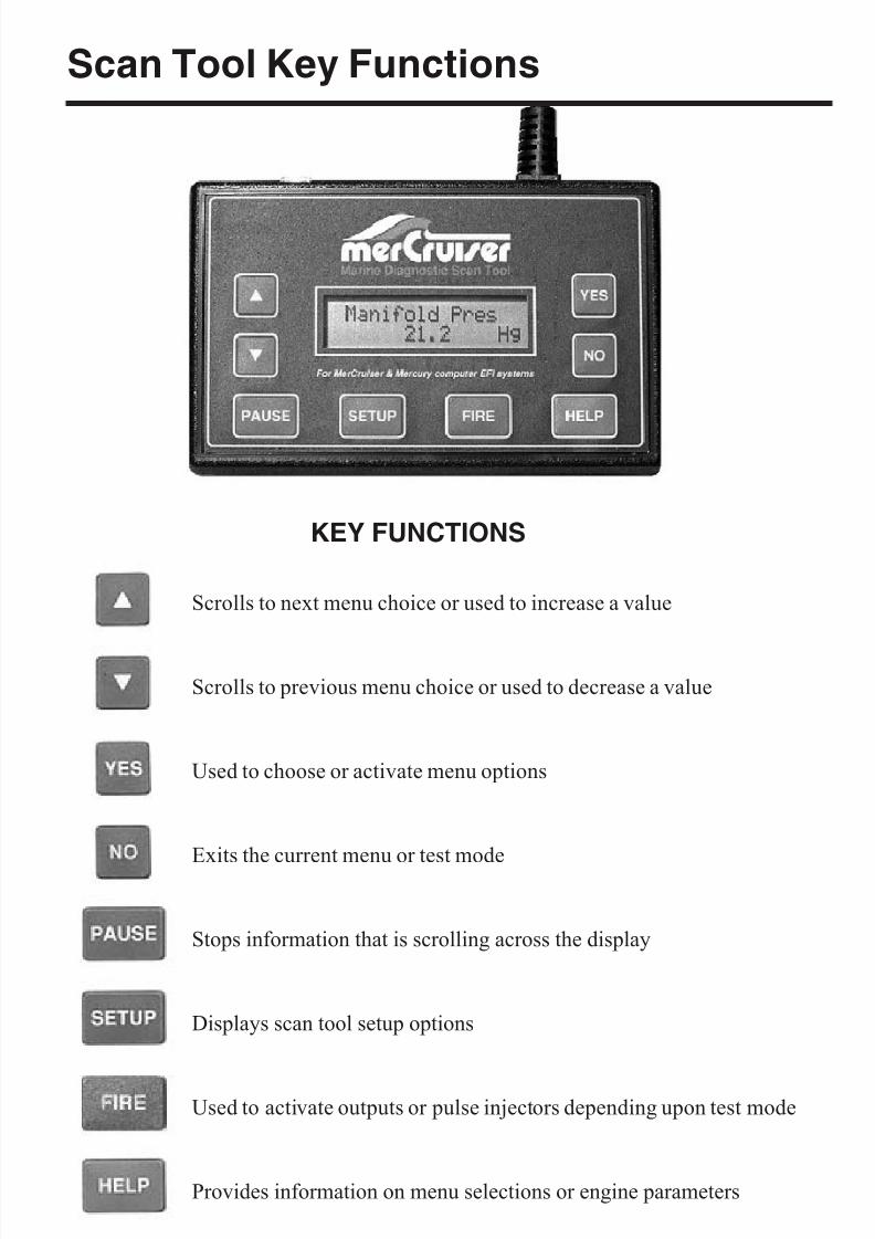
Scan Tool Key Functions
Page 4
Scrolls to next menu choice or used to increase a value
Scrolls to previous menu choice or used to decrease a value
Used to choose or activate menu options
Exits the current menu or test mode
Stops information that is scrolling across the display
Displays scan tool setup options
Used to activate outputs or pulse injectors depending upon test mode
Provides information on menu selections or engine parameters
KEY FUNCTIONS
8/8/2019 Merc Manual v5
http://slidepdf.com/reader/full/merc-manual-v5 9/76
Setup and Operation
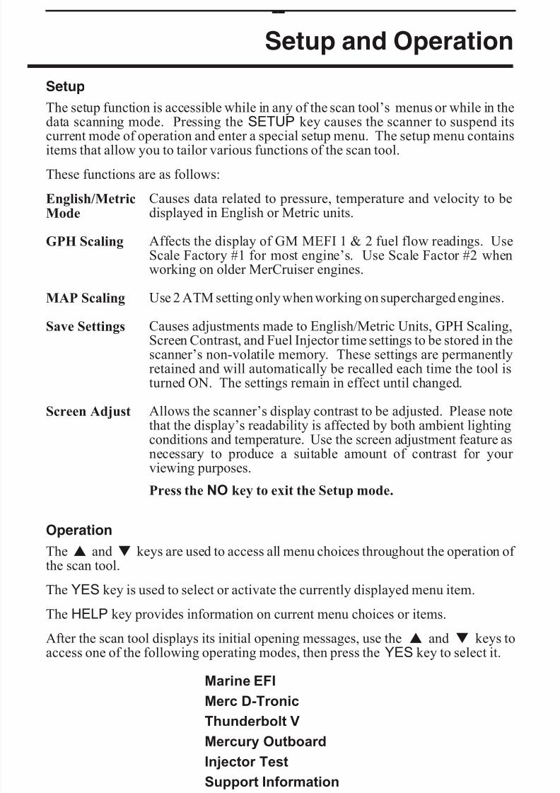
Setup
The setup function is accessible while in any of the scan tool’s menus or while in thedata scanning mode. Pressing the SETUP key causes the scanner to suspend its
current mode of operation and enter a special setup menu. The setup menu containsitems that allow you to tailor various functions of the scan tool.
These functions are as follows:
English/MetricMode
Causes data related to pressure, temperature and velocity to bedisplayed in English or Metric units.
GPH Scaling Affects the display of GM MEFI 1 & 2 fuel flow readings. UseScale Factory #1 for most engine’s. Use Scale Factor #2 whenworking on older MerCruiser engines.
MAP Scaling Use 2 ATM setting only when working on supercharged engines.
Save Settings Causes adjustments made to English/Metric Units, GPH Scaling,Screen Contrast, and Fuel Injector time settings to be stored in thescanner’s non-volatile memory. These settings are permanentlyretained and will automatically be recalled each time the tool isturned ON. The settings remain in effect until changed.
Screen Adjust Allows the scanner’s display contrast to be adjusted. Please notethat the display’s readability is affected by both ambient lightingconditions and temperature. Use the screen adjustment feature asnecessary to produce a suitable amount of contrast for your viewing purposes.
Press the NO key to exit the Setup mode.
Operation
The s and t keys are used to access all menu choices throughout the operation of the scan tool.
The YES key is used to select or activate the currently displayed menu item.
The HELP key provides information on current menu choices or items.
After the scan tool displays its initial opening messages, use the s and t keys toaccess one of the following operating modes, then press the YES key to select it.
Marine EFI
Merc D-Tronic
Thunderbolt V
Mercury Outboard
Injector Test
Support Information
Page 5
8/8/2019 Merc Manual v5
http://slidepdf.com/reader/full/merc-manual-v5 10/76
Function Flowchart
Page 6
C o n n e c t T o o l
S t a r t H e r e
8/8/2019 Merc Manual v5
http://slidepdf.com/reader/full/merc-manual-v5 11/76
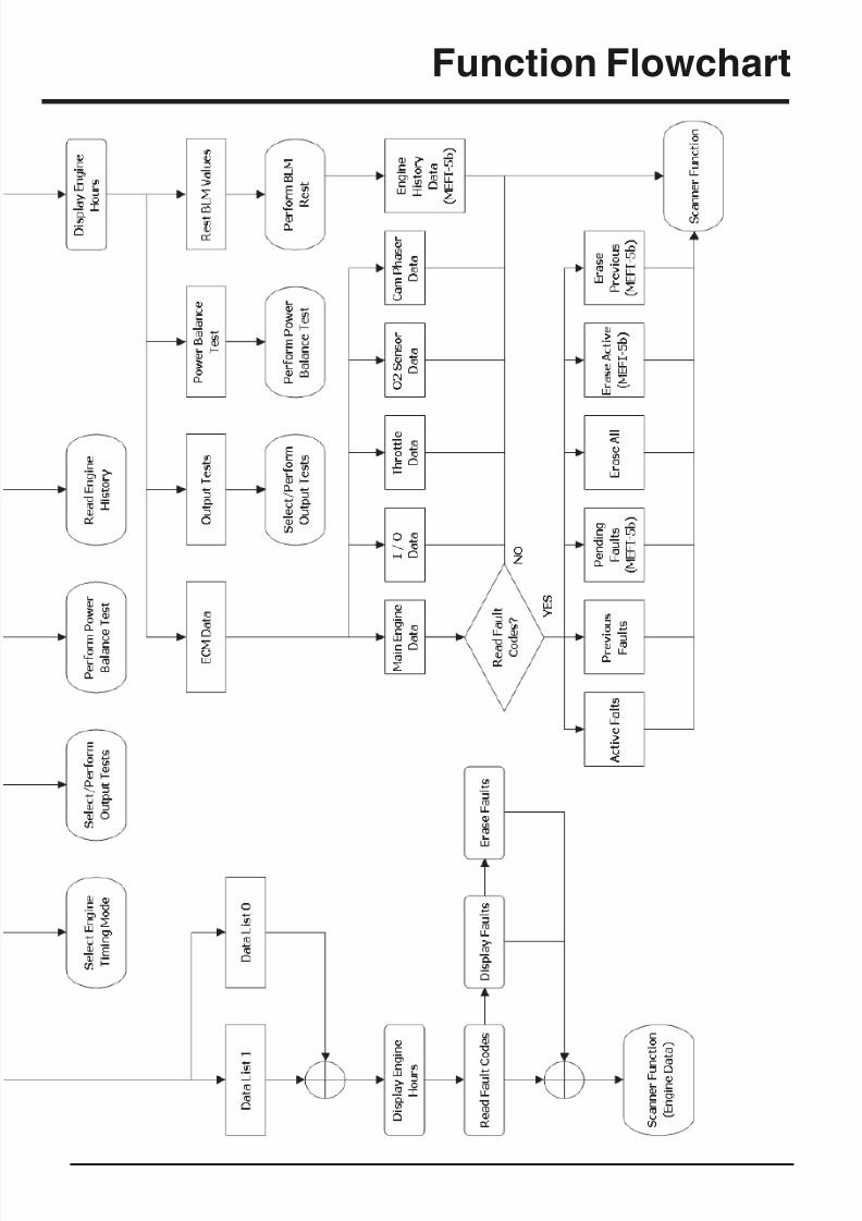
Function Flowchart
Page 7
8/8/2019 Merc Manual v5
http://slidepdf.com/reader/full/merc-manual-v5 12/76
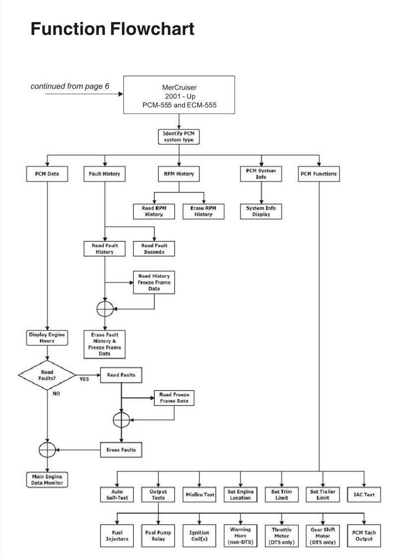
Function Flowchart
Page 8
MerCruiser
2001 - UpPCM-555 and ECM-555
continued from page 6
8/8/2019 Merc Manual v5
http://slidepdf.com/reader/full/merc-manual-v5 13/76
Page 9
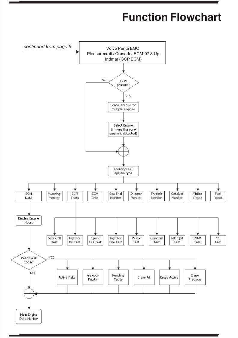
Function Flowchart
Volvo Penta EGC
Pleasurecraft / Crusader ECM-07 & Up
Indmar (GCP ECM)
continued from page 6
8/8/2019 Merc Manual v5
http://slidepdf.com/reader/full/merc-manual-v5 14/76
Function Flowchart
Page 10
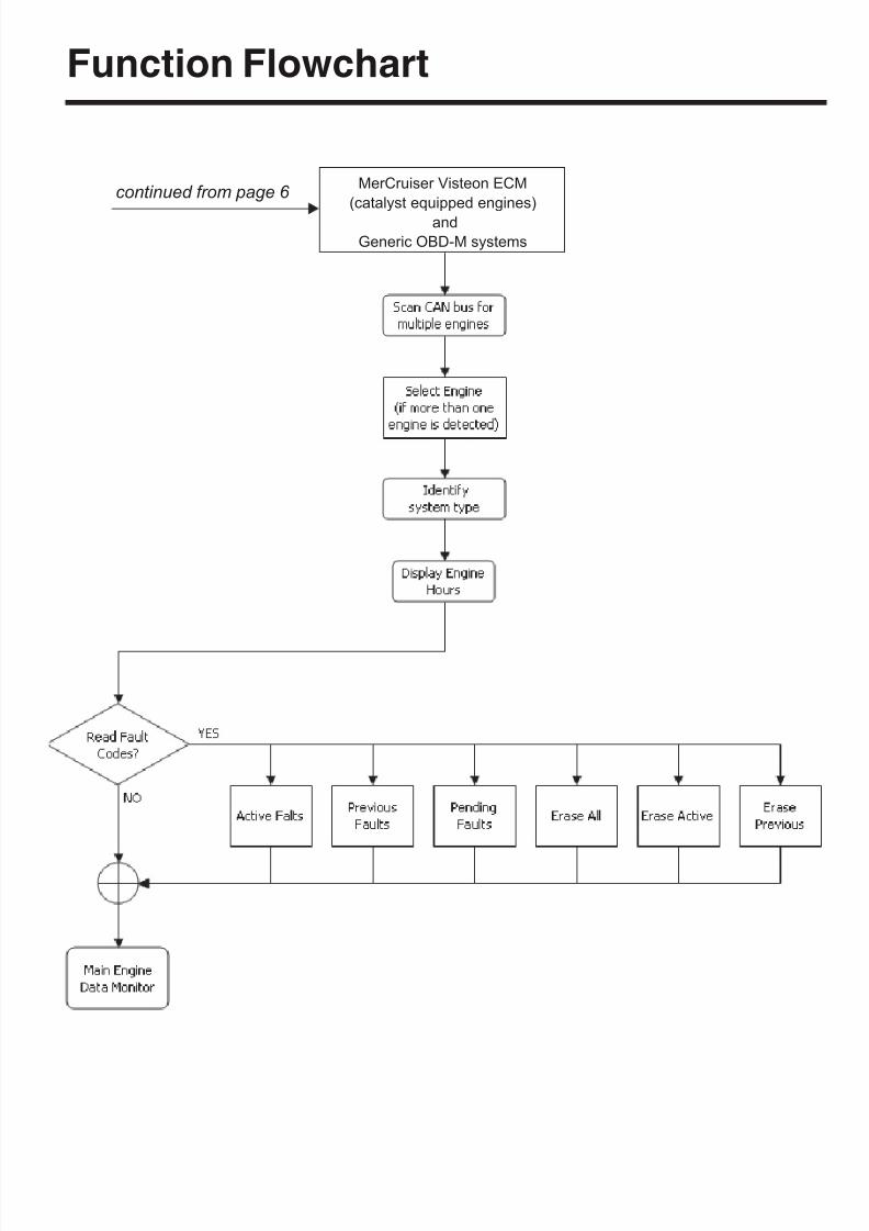
MerCruiser Visteon ECM
(catalyst equipped engines)
and
Generic OBD-M systems
continued from page 6
8/8/2019 Merc Manual v5
http://slidepdf.com/reader/full/merc-manual-v5 15/76
Engines Supported by the Scan Tool
Engine / EFI System Support
The MerCruiser Scan Tool supports a variety of electronic engine control systems as
summarized below. Please refer to the appropriate section of this manual based on thetype of engine control system being diagnosed.
· All marine engines equipped with GM MEFI (MEFI 1 thru MEFI 5)
· Volvo Penta engines equipped with EGC EFI
· Pleasurecraft / Crusader engines with ECM-07 & ECM-08 EFI
·
Indmar engine models equipped with GCP EFI· MerCruiser engines equipped with PCM-555 and ECM-555 EFI
· MerCruiser engines equipped with Visteon EFI
· OBD-M compliant sterndrive / inboard gasoline marine engines.
· MerCruiser engines with Thunderbolt V Ignition
· MerCruiser 2.8L and 4.2L D-Tronic Diesel Engines
· MerCruiser 7.3L D-Tronic Diesel Engines
· Mercury 3.0L Carbureted Outboard
· Mercury 3.0L EFI Outboard
· Mercury Hi-Performance 2.0L / 2.5L EFI Outboard
Page 11
8/8/2019 Merc Manual v5
http://slidepdf.com/reader/full/merc-manual-v5 16/76
GM Marine EFI
Scan Tool GM EFI Compatibility
At the date of publication of this manual, the MerCruiser Scan Tool is
compatible with 1993 and newer GM Marine EFI systems being used by avariety of marine engine manufacturers. These manufacturers include VolvoPenta, MerCruiser, Indmar, Crusader, Flagship, Marine Power, Pleasurecraft,and KEM. Please note that other manufacturers may also apply based uponnew product releases and MerCruiser Scan Tool software updates.
Gasoline ECMs Supported
The Marine EFI menu choice should be selected in order to service all 1993 and newer gasoline engines produced by Volvo Penta that are equipped with Electronic FuelInjection. This is the menu choice you will use most often.
Upon selecting the Marine EFI menu choice, the scan tool will establishcommunication with the engine’s Electronic Control Module (ECM) andautomatically determine the type of module that is present.
There are, at the time of this writing, five base GM marine system types that aresupported by the MerCruiser scan tool. Some of the system types shown below alsohave revisions that were released after their initial introductions which incorporatedrefinements. For example, MEFI-4 also had two follow-up revisions called MEFI-4a
and MEFI-4b. The scan tool currently supports all known GM MEFI revisions fromMEFI-1 through MEFI-5c.
Supported GM EFI system types:
· MEFI 1 (introduced in 1993)
· MEFI 2 (introduced in 1996)
· MEFI 3 (introduced in 1998)
· MEFI 4 (introduced in 2001)
· MEFI 5 (introduced in 2005)
Page 12
8/8/2019 Merc Manual v5
http://slidepdf.com/reader/full/merc-manual-v5 17/76
GM Marine EFI
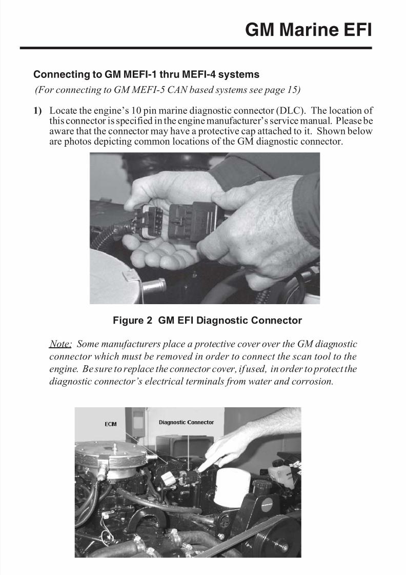
Connecting to GM MEFI-1 thru MEFI-4 systems
(For connecting to GM MEFI-5 CAN based systems see page 15)
1) Locate the engine’s 10 pin marine diagnostic connector (DLC). The location of this connector is specified in the engine manufacturer’s service manual. Please beaware that the connector may have a protective cap attached to it. Shown beloware photos depicting common locations of the GM diagnostic connector.
Note: Some manufacturers place a protective cover over the GM diagnostic
connector which must be removed in order to connect the scan tool to the
engine. Be sure to replace the connector cover, if used, in order to protect the
diagnostic connector’s electrical terminals from water and corrosion.
Page 13
Figure 2 GM EFI Diagnostic Connector
8/8/2019 Merc Manual v5
http://slidepdf.com/reader/full/merc-manual-v5 18/76
GM Marine EFI
2) With the engine’s ignition switch in the OFF position, plug the scan tool’scommunication cable into the diagnostic connector. Scan tool adapter #94005 isrequired for this application.
3) Once the tool is connected, turn the ignition switch ON and start the engine if necessary. If the engine will not start, simply leave the ignition switch ON and
proceed.
4) After the scan tool displays its initial opening messages, use the s and t keys to
select the “Marine EFI” operating mode, then press the YES key to select it.
Connecting Twin Engine Systems
In a twin engine configuration, the ECM modules (one on each engine) may beelectronically linked together. This link is usually installed by the boat manufacturer and provides the ability to diagnose both engines from a single diagnostic connector.With the exception of setting the engine’s base timing, all scanner functions areavailable for accessing both engines from one diagnostic plug. In order for thescanner to function properly in this mode, the ignition keys should be ON for BOTHengines. It is not necessary to have the engines running, but both ignition systems
should be turned on (Key On/Engine OFF).For twin installations that are NOT electronically linked together, you must connectto and service each engine individually. In this situation, each engine in the twininstallation will respond as Engine #1.
Engine #1 / Engine #2 Selection (MEFI ECMs Only)
This menu allows you to select which engine you would like to service. For a singleengine system, choose Engine #1.
For a twin engine system where the engines are electronically linked together, chooseEngine #1 or Engine #2.
If you are diagnosing a twin engine system that is NOT electronically linkedtogether, you must have the scanner attached to the diagnostic connector onthe engine you wish to service and choose Engine #1.
Remember, both ignition systems should be ON when troubleshooting anelectronically linked twin engine installation.
Page 14
8/8/2019 Merc Manual v5
http://slidepdf.com/reader/full/merc-manual-v5 19/76
GM Marine EFI
Connecting to GM MEFI-5 systems
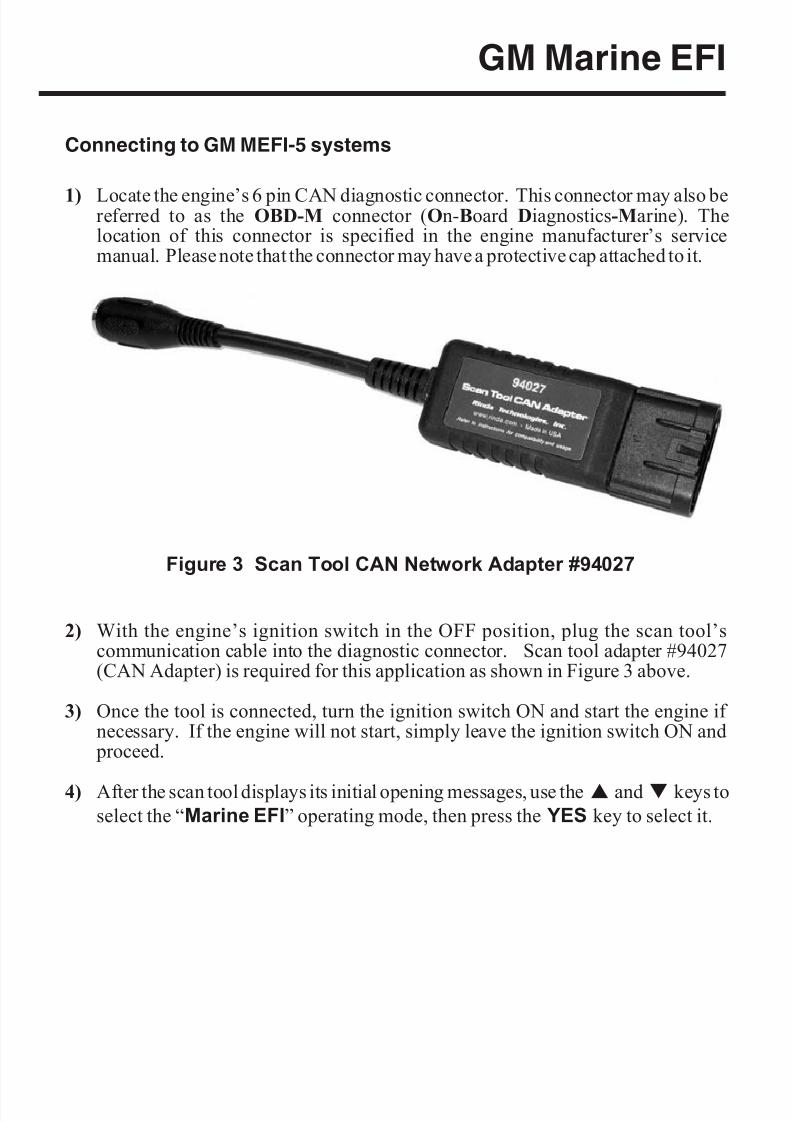
1) Locate the engine’s 6 pin CAN diagnostic connector. This connector may also bereferred to as the OBD-M connector (On-Board Diagnostics-Marine). Thelocation of this connector is specified in the engine manufacturer’s servicemanual. Please note that the connector may have a protective cap attached to it.
2) With the engine’s ignition switch in the OFF position, plug the scan tool’scommunication cable into the diagnostic connector. Scan tool adapter #94027(CAN Adapter) is required for this application as shown in Figure 3 above.
3) Once the tool is connected, turn the ignition switch ON and start the engine if necessary. If the engine will not start, simply leave the ignition switch ON and
proceed.
4) After the scan tool displays its initial opening messages, use the s and t keys toselect the “Marine EFI” operating mode, then press the YES key to select it.
Page 15
Figure 3 Scan Tool CAN Network Adapter #94027
8/8/2019 Merc Manual v5
http://slidepdf.com/reader/full/merc-manual-v5 20/76
GM Marine EFI
Obtaining Data
After selecting the “Marine EFI” function the scan tool will attempt to communicate
with the engine’s fuel injection computer and automatically identify it. After anidentification is made, you will be presented with several menu choices. To obtaindiagnostic data and system trouble codes, select the “ECM Data” function. Thismenu choice causes the scanner to begin reading information from the ECM module.The scanner will prompt for your input as follows:
1) After choosing the ECM data function, the scanner may prompt you to choose adata list(MEFI-1 thru MEFI-4 systems only). Select Data List #1 or Data List #0.
Data List #1 contains diagnostic service information and will usually be of
primary interest to you.
Data List #0 contains a smaller number of information items and is intended for electronic instrumentation purposes.
2) The scanner will now attempt to communicate with the engine’s computer andautomatically determine what version of ECM is installed on the engine.
3) Next, the scanner will provide you with the number of Operating Hours theengine has logged. Once displayed, the scanner will interrogate the ECM and
obtain any stored Fault Codes. If any codes are detected, they will be displayedalong with their descriptions. Options will be displayed allowing you to Reviewas well as Erase the stored codes.
4) The tool will now enter its “Scanner” mode and allow you to select and display awide variety of engine sensor and operating information. The displayed data isupdated several times per second. Use the s and t keys to scroll through theavailable information. Use the HELP key to access information on the currentlydisplayed engine parameter. Use the NO key to exit the “Scanner” mode andreturn to the main menu.
Page 16
8/8/2019 Merc Manual v5
http://slidepdf.com/reader/full/merc-manual-v5 21/76
GM Marine EFI
Page 17
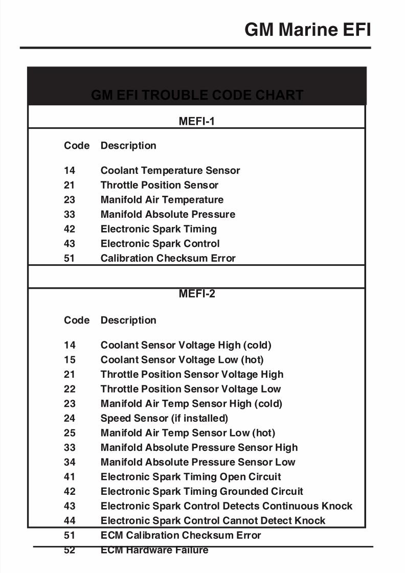
MEFI-1
Code Description
14 Coolant Temperature Sensor
21 Throttle Position Sensor
23 Manifold Air Temperature33 Manifold Absolute Pressure
42 Electronic Spark Timing
43 Electronic Spark Control
51 Calibration Checksum Error
MEFI-2
Code Description
14 Coolant Sensor Voltage High (cold)
15 Coolant Sensor Voltage Low (hot)
21 Throttle Position Sensor Voltage High
22 Throttle Position Sensor Voltage Low
23 Manifold Air Temp Sensor High (cold)
24 Speed Sensor (if installed)
25 Manifold Air Temp Sensor Low (hot)
33 Manifold Absolute Pressure Sensor High
34 Manifold Absolute Pressure Sensor Low
41 Electronic Spark Timing Open Circuit
42 Electronic Spark Timing Grounded Circuit
43 Electronic Spark Control Detects Continuous Knock
44 Electronic Spark Control Cannot Detect Knock
51 ECM Calibration Checksum Error
52 ECM Hardware Failure
GM EFI TROUBLE CODE CHART
8/8/2019 Merc Manual v5
http://slidepdf.com/reader/full/merc-manual-v5 22/76
GM Marine EFI
Page 18
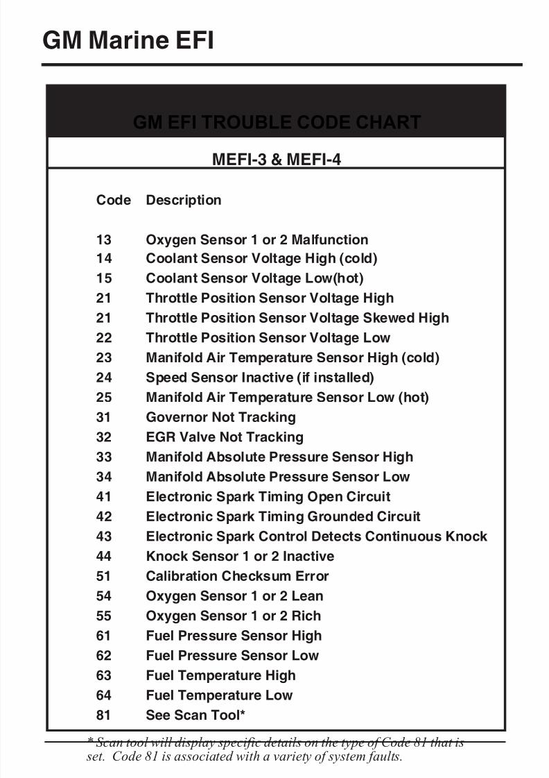
GM EFI TROUBLE CODE CHART
MEFI-3 & MEFI-4
Code Description
13 Oxygen Sensor 1 or 2 Malfunction
14 Coolant Sensor Voltage High (cold)
15 Coolant Sensor Voltage Low(hot)
21 Throttle Position Sensor Voltage High
21 Throttle Position Sensor Voltage Skewed High
22 Throttle Position Sensor Voltage Low
23 Manifold Air Temperature Sensor High (cold)
24 Speed Sensor Inactive (if installed)
25 Manifold Air Temperature Sensor Low (hot)
31 Governor Not Tracking
32 EGR Valve Not Tracking
33 Manifold Absolute Pressure Sensor High
34 Manifold Absolute Pressure Sensor Low
41 Electronic Spark Timing Open Circuit
42 Electronic Spark Timing Grounded Circuit
43 Electronic Spark Control Detects Continuous Knock
44 Knock Sensor 1 or 2 Inactive
51 Calibration Checksum Error
54 Oxygen Sensor 1 or 2 Lean
55 Oxygen Sensor 1 or 2 Rich
61 Fuel Pressure Sensor High
62 Fuel Pressure Sensor Low
63 Fuel Temperature High64 Fuel Temperature Low
81 See Scan Tool*
* Scan tool will display specific details on the type of Code 81 that is set. Code 81 is associated with a variety of system faults.
8/8/2019 Merc Manual v5
http://slidepdf.com/reader/full/merc-manual-v5 23/76
GM Marine EFI
Page 19
GM EFI TROUBLE CODE CHART
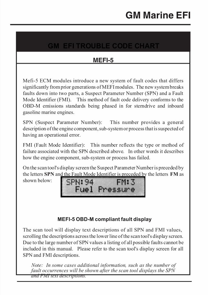
MEFI-5
Mefi-5 ECM modules introduce a new system of fault codes that differs
significantly from prior generations of MEFI modules. The new system breaks
faults down into two parts, a Suspect Parameter Number (SPN) and a Fault
Mode Identifier (FMI). This method of fault code delivery conforms to the
OBD-M emissions standards being phased in for sterndrive and inboard
gasoline marine engines.
SPN (Suspect Parameter Number): This number provides a general
description of the engine component, sub-system or process that is suspected of
having an operational error.
FMI (Fault Mode Identifier): This number reflects the type or method of
failure associated with the SPN described above. In other words it describes
how the engine component, sub-system or process has failed.
On the scan tool's display screen the Suspect Parameter Number is preceded by
the letters SPN and the Fault Mode Identifier is preceded by the letters FM as
shown below:
The scan tool will display text descriptions of all SPN and FMI values,
scrolling the descriptions across the lower line of the scan tool's display screen.
Due to the large number of SPN values a listing of all possible faults cannot be
included in this manual. Please refer to the scan tool's display screen for all
SPN and FMI descriptions.
Note: In some cases additional information, such as the number of fault occurrences will be shown after the scan tool displays the SPN and FMI text descriptions.
MEFI-5 OBD-M compliant fault display
8/8/2019 Merc Manual v5
http://slidepdf.com/reader/full/merc-manual-v5 24/76
GM Marine EFI
Service Mode Function (MEFI-1 thru MEFI-4 ECMs Only)
The Service Mode function is primarily used to set an engine’s base spark timing.This function normally applies to engines equipped with a mechanical distributor and
is typically not used on engines with Distributorless Ignition Systems (DIS) unlessotherwise specified. Upon selecting the Service Mode menu option, the currentlyactive mode will be displayed and you will have the choice of selecting either the
Normal or Service Modes. Simply select the desired mode then continue on to perform other scanner functions if necessary. The “Service” mode will stay activateduntil changed by entering the Service Mode function again and selecting a differentmode or by disconnecting the scan tool.
Special note for twin engine systems:
In order for the service Mode to function properly on twin engine systems, youmust have the scan tool attached to the Diagnostic Connector on the enginebeing serviced.
Power Balance Test (MEFI-4 & MEFI-5 ECMs Only)
The Power Balance Test is designed to assist a technician in finding a problematiccylinder. This test commands the ECM to disable the spark output, or on some
systems both spark and fuel, to a selected cylinder thereby causing that cylinder tomisfire (not produce power). This test must be enabled by the engine manufacturer.Upon selecting the Power Balance Test the scan tool will query the ECM to see if thetest is available.
The objective of this test is to determine whether or not disabling a particular cylinder will cause a drop in engine RPM. If a cylinder is disabled and the RPM remains thesame it is likely that the disabled cylinder is problematic and not producing power under normal operating conditions. Please refer to the engine manufacturer's service
literature for more information on this test.
· IMPORTANT: This test should be performed with the enginerunning at approximately 1500 rpm, at normal operatingtemperature and under moderate load.
· Do not attempt to drive the boat while performing this test.
· Follow all engine and boat manufacturer’s safety precautions
and stay clear of all moving engine components.
· Refer to the engine manufacturer’s service manual for specialnotes on performing this test.
.
Page 20
8/8/2019 Merc Manual v5
http://slidepdf.com/reader/full/merc-manual-v5 25/76
GM Marine EFI
Reset BLM Values (MEFI-5 only)
This function applies to MEFI-5 based engine that are equipped with oxygen sensors.During engine operation the ECM learns and stores modifications to it's factory preset
fuel delivery values. This allows the ECM to adapt itself to the unique operatingconditions it is subjected to in a particular engine application. The Reset BLMfunction allows a service technician to clear the ECM's learned values and reset thesystem back to factory default conditions.
Note: Always consult the engine manufacturer's service literature prior to performing this function. Under normal circumstances resetting the BLM values should not need to be performed unless specified by the enginemanufacturer.
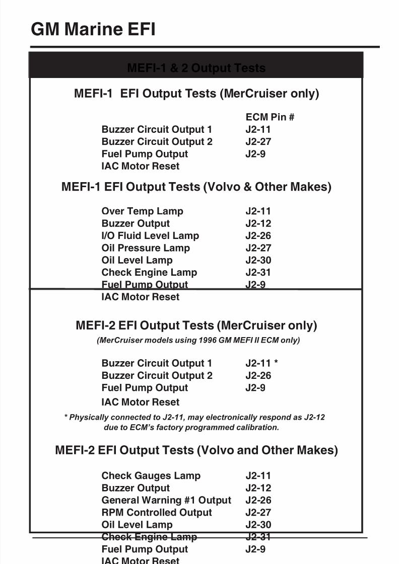
ECM Output Tests Function
The MerCruiser scan tool has the ability to activate a number of ECM outputs for diagnostic purposes. Upon selecting the ECM Output Tests menu choice the scanner will interrogate the ECM in order to determine its version type. You will then be
presented with a menu listing all ECM outputs the scanner is capable of triggering.Outputs are normally activated for one-second intervals. You may continue to cycle a
particular output numerous times by pressing the scanner’s FIRE key.
WARNING! Please note that each engine manufacturer may useindividual ECM outputs for functions other than those listed on thefollowing pages. In order to avoid personal injury and unexpecteddevice activation, always refer to the engine manufacturer’s servicemanual before performing any output test
Page 21
8/8/2019 Merc Manual v5
http://slidepdf.com/reader/full/merc-manual-v5 26/76
GM Marine EFI
Page 22
MEFI-1 EFI Output Tests (MerCruiser only)ECM Pin #
Buzzer Circuit Output 1 J2-11
Buzzer Circuit Output 2 J2-27
Fuel Pump Output J2-9
IAC Motor Reset
MEFI-1 EFI Output Tests (Volvo & Other Makes)
Over Temp Lamp J2-11
Buzzer Output J2-12
I/O Fluid Level Lamp J2-26
Oil Pressure Lamp J2-27
Oil Level Lamp J2-30
Check Engine Lamp J2-31
Fuel Pump Output J2-9
IAC Motor Reset
MEFI-2 EFI Output Tests (MerCruiser only)(MerCruiser models using 1996 GM MEFI II ECM only)
Buzzer Circuit Output 1 J2-11 *
Buzzer Circuit Output 2 J2-26
Fuel Pump Output J2-9
IAC Motor Reset
* Physically connected to J2-11, may electronically respond as J2-12
due to ECM’s factory programmed calibration.
MEFI-2 EFI Output Tests (Volvo and Other Makes)
Check Gauges Lamp J2-11
Buzzer Output J2-12
General Warning #1 Output J2-26
RPM Controlled Output J2-27
Oil Level Lamp J2-30
Check Engine Lamp J2-31
Fuel Pump Output J2-9
IAC Motor Reset
MEFI-1 & 2 Output Tests
8/8/2019 Merc Manual v5
http://slidepdf.com/reader/full/merc-manual-v5 27/76
GM Marine EFI
Page 23
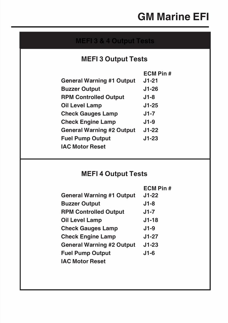
MEFI 3 Output Tests
ECM Pin #
General Warning #1 Output J1-21
Buzzer Output J1-26
RPM Controlled Output J1-8
Oil Level Lamp J1-25
Check Gauges Lamp J1-7Check Engine Lamp J1-9
General Warning #2 Output J1-22
Fuel Pump Output J1-23
IAC Motor Reset
MEFI 4 Output Tests
ECM Pin #
General Warning #1 Output J1-22
Buzzer Output J1-8
RPM Controlled Output J1-7
Oil Level Lamp J1-18
Check Gauges Lamp J1-9
Check Engine Lamp J1-27
General Warning #2 Output J1-23
Fuel Pump Output J1-6
IAC Motor Reset
MEFI 3 & 4 Output Tests
8/8/2019 Merc Manual v5
http://slidepdf.com/reader/full/merc-manual-v5 28/76
GM Marine EFI
Page 24
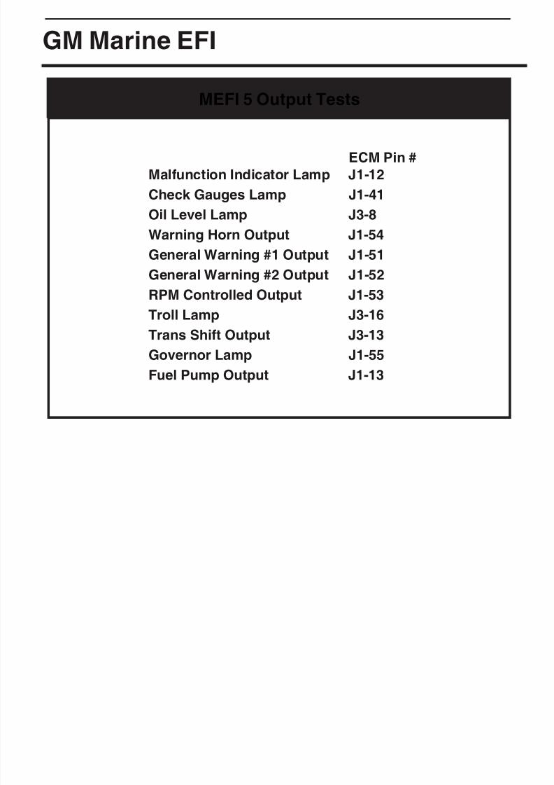
MEFI 5 Output Tests
ECM Pin #
Malfunction Indicator Lamp J1-12
Check Gauges Lamp J1-41
Oil Level Lamp J3-8
Warning Horn Output J1-54
General Warning #1 Output J1-51
General Warning #2 Output J1-52RPM Controlled Output J1-53
Troll Lamp J3-16
Trans Shift Output J3-13
Governor Lamp J1-55
Fuel Pump Output J1-13

8/8/2019 Merc Manual v5
http://slidepdf.com/reader/full/merc-manual-v5 29/76
Volvo Penta EGC
This section describes scan tool functions related to marine engines equipped withVolvo Penta EGC (Electronic Gas Control) fuel injection systems. This system wasintroduced on Volvo Penta gasoline marine engines for the 2006 model year.
Connecting to the Volvo Penta EGC System
The MerCruiser scan tool provides a comprehensive set of diagnostic and supportfunctions for troubleshooting EGC equipped engines. Connection and operation of the tool is simple and straight forward.
1) Locate the engine’s diagnostic connector (DLC). The exact location of thisconnector is specified in the engine manufacturer’s service manual and may varydepending upon the engine type. Please be aware that the connector may have a
protective cap attached to it.
2) With the engine’s ignition switch in the OFF position, plug the scan tool’scommunication cable into the diagnostic connector. For 2006 & 2007 EGCsystems use adapter #94024, for 2008 and newer systems use adapter #94027.
Page 25
Volvo Penta EGC Control Module
Volvo Penta EGC Adapter for 2006 & 2007 EGC systems
Rinda Tech P/N 94024
Scan Tool CAN Network Adapter for 2008-Up EGC systems
Rinda Tech P/N 94027
8/8/2019 Merc Manual v5
http://slidepdf.com/reader/full/merc-manual-v5 30/76
Volvo Penta EGC
3) Once the tool is connected, turn the ignition switch ON and start the engine if necessary. If the engine will not start, leave the ignition switch ON and proceed.
4) After the scan tool displays its initial opening messages, use the s and t keys todisplay the “MARINE EFI” operating mode from the main menu, then press the
YES key to select it.
Obtaining General Diagnostic Data
After selecting the “MARINE EFI” function the scan tool will attempt tocommunicate with the engine’s fuel injection computer and automatically identify it.After an identification is made you will be presented with several menu choices. To
obtain general diagnostic data and system trouble codes, select the “ECM Data”function. This menu choice causes the scanner to begin reading information from theVolvo EGC module. The scanner will prompt for your input as follows:
1) After selecting the “ECM Data“ function the scanner will communicate with theengine’s EGC control module and automatically provide you with the number of Operating Hours the engine has logged.
2) Once the engine operating hours have been displayed the scanner will prompt you
to scan for trouble codes. Selecting YES will cause the scanner to interrogate theEGC’s trouble code memory. If any codes are present, their descriptions will bedisplayed. After the trouble code description is displayed you will be prompted toview optional information associated with each code. This information includeswhether the code was set during the current ignition cycle and the number of engine restarts since the code was set.
3) After trouble codes are displayed the scan tool will provide an option to Erase thestored codes.
Viewing Specialized Diagnostic DataIn addition to providing general diagnostic data as described above, the scan tool
provides several other data lists that are each tailored for a specific purpose. Theselists vary based upon EGC system type and are accessible from the main Volvo PentaEGC system menu. All lists may not be available on a particular EGC system type.
Warning Monitor data list:
This data list provides quick access to a subset of EGC parameters and statusindicators that are considered system critical. Parameters displayed in this list
provide a technician with a summary of important operating data such as oil pressure,engine temperature, MIL status as well as other critical engine indicators.
Page 26
8/8/2019 Merc Manual v5
http://slidepdf.com/reader/full/merc-manual-v5 31/76
Page 27
Volvo Penta EGC
ECM Information data list:
Selecting this data list allows a technician to view version, serial number and
calibration information related to the engine and EGC module. This informationincludes a variety of non-diagnostic data including hardware and software versionnumbers, calibration checksums, serial numbers and engine firing order data.
Sea Trial Monitor data list:
The sea trial monitor data list includes a short set of engine parameters that are usefulwhen performing boat tests. Information available in this data list includes enginespeed, fuel flow rate, engine load and throttle position data.
Injector Monitor data list:
This data list provides a set of ON and OFF voltages for each fuel injector driver. Byviewing the EGC module’s injector output voltage levels a technician can quicklyisolate fuel injector electrical failures.
Throttle Monitor data list:
This list is available only when connected to an engine that is equipped withElectronic Throttle Control (ETC). The throttle monitor data list provides quick access to EGC system parameters that are critical to electronic throttle operation. Acomplete set of items related to throttle lever position and throttle blade angle are
provided to assist in diagnosing ETC related problems.
O2 / Misfire Monitor data list:
This list is available only when oxygen sensors and catalytic converters are present onan EGC equipped engine. This data list provides access to O2 sensor, catalyst andengine misfire information.
Special Reset Functions for O2 / Catalyst equipped engines.
Reset Fuel Adapt
Allows a service technician to clear the ECM's learned fuel delivery values and resetthe system back to factory default conditions. Consult the engine manufacturer'sservice literature prior to using this function.
Reset Misfire Data
Clears the ECM's stored cylinder misfire data. Consult the engine manufacturer'sservice literature prior to using this function.
8/8/2019 Merc Manual v5
http://slidepdf.com/reader/full/merc-manual-v5 32/76
Volvo Penta EGC
ECM Tests
The ECM TESTS option provides access to a variety of EGC functional tests.
·
IMPORTANT: Before performing any ECM or engine test refer tothe engine manufacturer's service literature for safety precau-tions and proper engine test procedures.
To access the ECM TESTS menu perform the following steps:
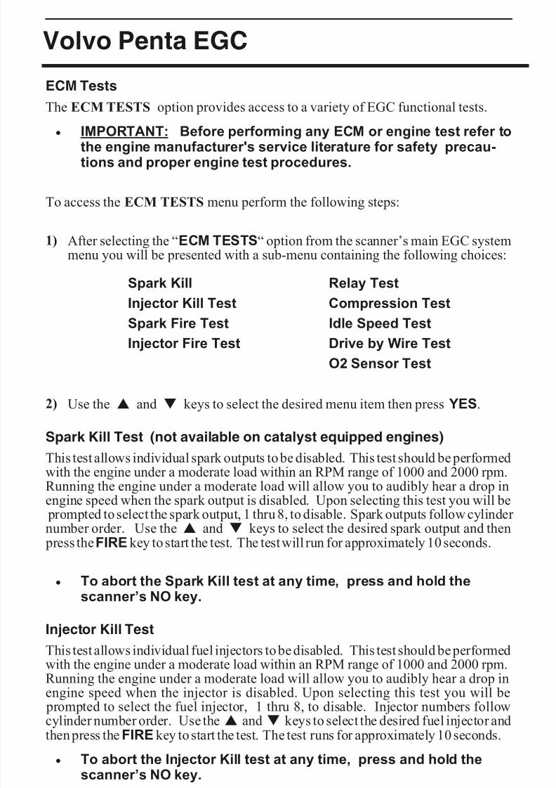
1) After selecting the “ECM TESTS“ option from the scanner’s main EGC systemmenu you will be presented with a sub-menu containing the following choices:
Spark Kill Relay Test
Injector Kill Test Compression Test
Spark Fire Test Idle Speed Test
Injector Fire Test Drive by Wire Test
O2 Sensor Test
2) Use the s and t keys to select the desired menu item then press YES.
Spark Kill Test (not available on catalyst equipped engines)
This test allows individual spark outputs to be disabled. This test should be performedwith the engine under a moderate load within an RPM range of 1000 and 2000 rpm.Running the engine under a moderate load will allow you to audibly hear a drop inengine speed when the spark output is disabled. Upon selecting this test you will be
prompted to select the spark output, 1 thru 8, to disable. Spark outputs follow cylinder number order. Use the s and t keys to select the desired spark output and then
press the FIRE key to start the test. The test will run for approximately 10 seconds.
· To abort the Spark Kill test at any time, press and hold thescanner’s NO key.
Injector Kill Test
This test allows individual fuel injectors to be disabled. This test should be performedwith the engine under a moderate load within an RPM range of 1000 and 2000 rpm.Running the engine under a moderate load will allow you to audibly hear a drop in
engine speed when the injector is disabled. Upon selecting this test you will be prompted to select the fuel injector, 1 thru 8, to disable. Injector numbers followcylinder number order. Use the s and t keys to select the desired fuel injector andthen press the FIRE key to start the test. The test runs for approximately 10 seconds.
· To abort the Injector Kill test at any time, press and hold thescanner’s NO key.
Page 28
8/8/2019 Merc Manual v5
http://slidepdf.com/reader/full/merc-manual-v5 33/76
Volvo Penta EGC
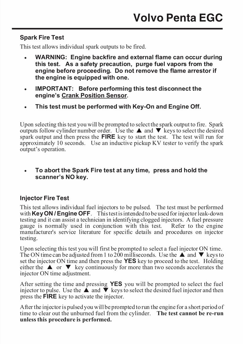
Spark Fire Test
This test allows individual spark outputs to be fired.
·
WARNING: Engine backfire and external flame can occur duringthis test. As a safety precaution, purge fuel vapors from theengine before proceeding. Do not remove the flame arrestor if the engine is equipped with one.
· IMPORTANT: Before performing this test disconnect theengine’s Crank Position Sensor.
· This test must be performed with Key-On and Engine Off.
Upon selecting this test you will be prompted to select the spark output to fire. Spark outputs follow cylinder number order. Use the s and t keys to select the desiredspark output and then press the FIRE key to start the test. The test will run for approximately 10 seconds. Use an inductive pickup KV tester to verify the spark output’s operation.
· To abort the Spark Fire test at any time, press and hold thescanner’s NO key.
Injector Fire Test
This test allows individual fuel injectors to be pulsed. The test must be performedwith Key ON / Engine OFF. This test is intended to be used for injector leak-downtesting and it can assist a technician in identifying clogged injectors. A fuel pressuregauge is normally used in conjunction with this test. Refer to the enginemanufacturer's service literature for specific details and procedures on injector
testing.Upon selecting this test you will first be prompted to select a fuel injector ON time.The ON time can be adjusted from 1 to 200 milliseconds. Use the s and t keys toset the injector ON time and then press the YES key to proceed to the test. Holdingeither the s or t key continuously for more than two seconds accelerates theinjector ON time adjustment.
After setting the time and pressing YES you will be prompted to select the fuelinjector to pulse. Use the s and t keys to select the desired fuel injector and then
press the FIRE key to activate the injector.
After the injector is pulsed you will be prompted to run the engine for a short period of time to clear out the unburned fuel from the cylinder. The test cannot be re-rununless this procedure is performed.
Page 29
8/8/2019 Merc Manual v5
http://slidepdf.com/reader/full/merc-manual-v5 34/76
Volvo Penta EGC
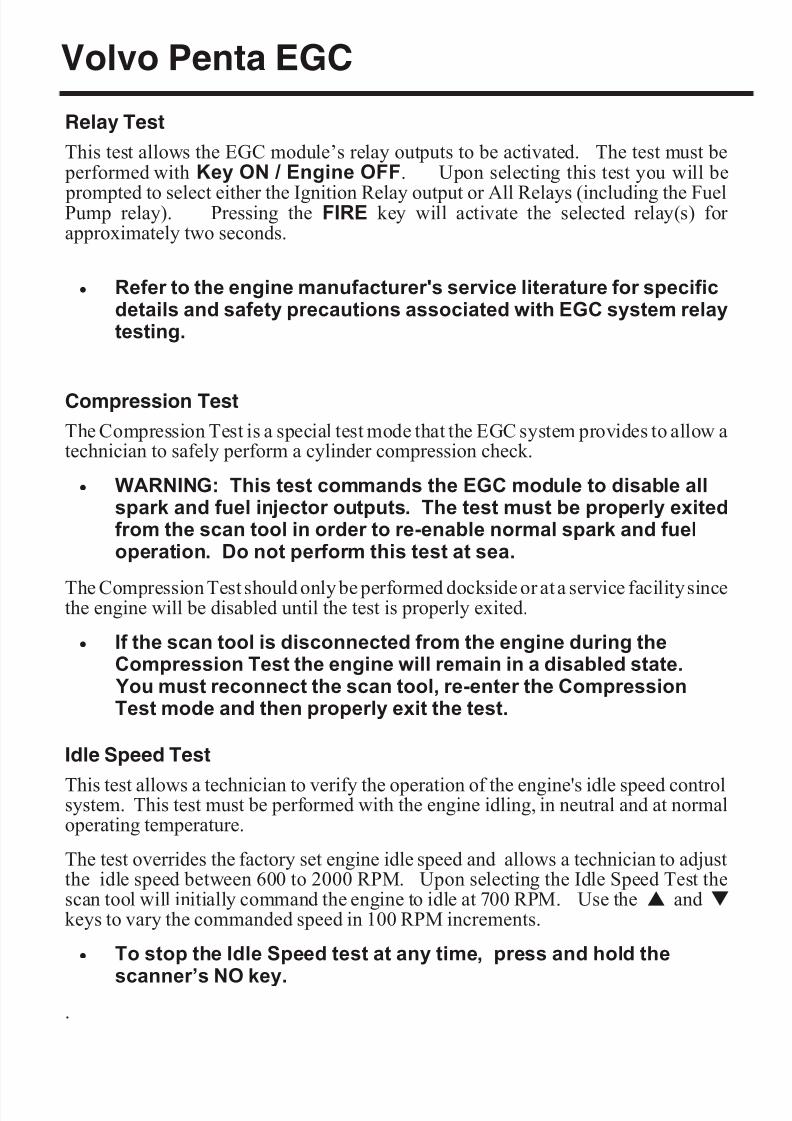
Relay Test
This test allows the EGC module’s relay outputs to be activated. The test must be performed with Key ON / Engine OFF. Upon selecting this test you will be
prompted to select either the Ignition Relay output or All Relays (including the FuelPump relay). Pressing the FIRE key will activate the selected relay(s) for approximately two seconds.
· Refer to the engine manufacturer's service literature for specificdetails and safety precautions associated with EGC system relaytesting.
Compression Test
The Compression Test is a special test mode that the EGC system provides to allow atechnician to safely perform a cylinder compression check.
· WARNING: This test commands the EGC module to disable allspark and fuel injector outputs. The test must be properly exitedfrom the scan tool in order to re-enable normal spark and fueloperation. Do not perform this test at sea.
The Compression Test should only be performed dockside or at a service facility sincethe engine will be disabled until the test is properly exited.
· If the scan tool is disconnected from the engine during theCompression Test the engine will remain in a disabled state. You must reconnect the scan tool, re-enter the CompressionTest mode and then properly exit the test.
Idle Speed Test
This test allows a technician to verify the operation of the engine's idle speed controlsystem. This test must be performed with the engine idling, in neutral and at normaloperating temperature.
The test overrides the factory set engine idle speed and allows a technician to adjustthe idle speed between 600 to 2000 RPM. Upon selecting the Idle Speed Test thescan tool will initially command the engine to idle at 700 RPM. Use the s and tkeys to vary the commanded speed in 100 RPM increments.
· To stop the Idle Speed test at any time, press and hold the
scanner’s NO key..
Page 30

8/8/2019 Merc Manual v5
http://slidepdf.com/reader/full/merc-manual-v5 35/76
Volvo Penta EGC
Drive by Wire Test
This test is available only when connected to engines equipped with ElectronicThrottle Control (ETC). The test allows a technician to check the functionality of the
ETC system by commanding the engine throttle blade to track helm throttle controllever movements.
This test must be performed with Key ON / Engine OFF. Upon selecting this testyou will be prompted to move the helm throttle lever and observe movements of theengine throttle blade. The scan tool will also display the commanded ThrottleControl Position percentage as well as the commanded Throttle Position
percentage (percentage of throttle blade movement).
· To stop the Drive by Wire test at any time, press and hold the
scanner’s NO key.
O2 Sensor Test (O2 / catalyst equipped engines only)
This test is available only when connected to an engine equipped with oxygen sensorsand one or more catalytic converters. The test allows a technician to check thefunctionality of the O2 sensor feedback system by automatically cycling the enginethrough rich and lean phases of operation. This test must be performed with theengine idling and gear selector in the Neutral position.
· The engine's speed will be increased to approximately 1200 rpmduring the test.
· To abort the O2 Sensor test at any time, press and hold thescanner’s NO key.
This test runs automatically and consists of several phases of operation. The particular phase being executed by the ECM will be indicated on the scan tool'sdisplay screen. Also displayed is the elapsed time that the test has been in progress asshown in the photo below.
When the O2 sensor test is complete the scan tool will scroll messages across itsscreen displaying the results of the pre-catalyst and post-catalyst oxygen sensors. Amessage will also be displayed instructing the technician to scan for ECM fault codesto obtain additional information on any O2 sensor problem that was detected duringthe test.
Page 31
O2 Sensor Test display
8/8/2019 Merc Manual v5
http://slidepdf.com/reader/full/merc-manual-v5 36/76
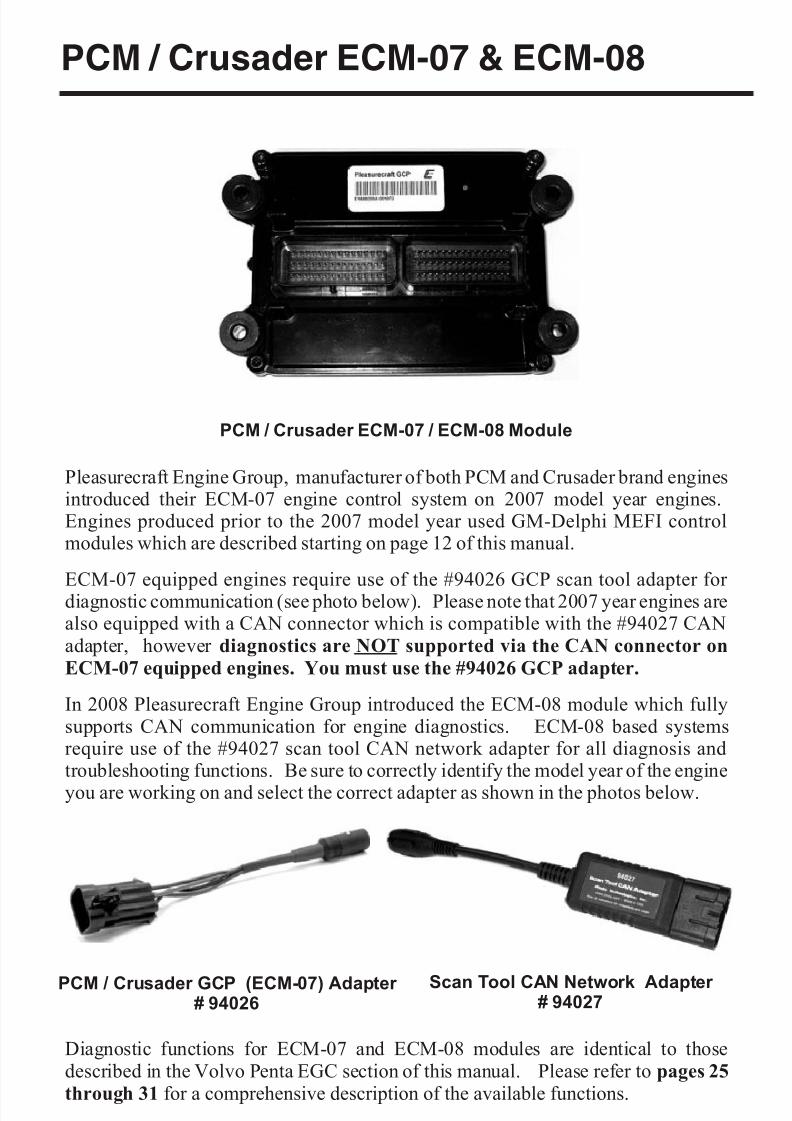
PCM / Crusader ECM-07 & ECM-08
Pleasurecraft Engine Group, manufacturer of both PCM and Crusader brand enginesintroduced their ECM-07 engine control system on 2007 model year engines.Engines produced prior to the 2007 model year used GM-Delphi MEFI controlmodules which are described starting on page 12 of this manual.
ECM-07 equipped engines require use of the #94026 GCP scan tool adapter for diagnostic communication (see photo below). Please note that 2007 year engines arealso equipped with a CAN connector which is compatible with the #94027 CANadapter, however diagnostics are NOT supported via the CAN connector on
ECM-07 equipped engines. You must use the #94026 GCP adapter.
In 2008 Pleasurecraft Engine Group introduced the ECM-08 module which fullysupports CAN communication for engine diagnostics. ECM-08 based systemsrequire use of the #94027 scan tool CAN network adapter for all diagnosis andtroubleshooting functions. Be sure to correctly identify the model year of the engine
you are working on and select the correct adapter as shown in the photos below.
Diagnostic functions for ECM-07 and ECM-08 modules are identical to thosedescribed in the Volvo Penta EGC section of this manual. Please refer to pages 25
through 31 for a comprehensive description of the available functions.
Page 32
PCM / Crusader ECM-07 / ECM-08 Module
PCM / Crusader GCP (ECM-07) Adapter # 94026
Scan Tool CAN Network Adapter # 94027
8/8/2019 Merc Manual v5
http://slidepdf.com/reader/full/merc-manual-v5 37/76
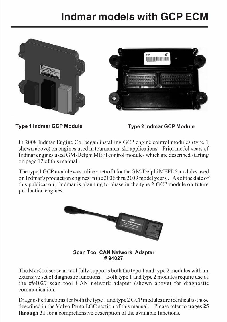
Indmar models with GCP ECM
In 2008 Indmar Engine Co. began installing GCP engine control modules (type 1shown above) on engines used in tournament ski applications. Prior model years of Indmar engines used GM-Delphi MEFI control modules which are described startingon page 12 of this manual.
The type 1 GCP module was a direct retrofit for the GM-Delphi MEFI-5 modules usedon Indmar's production engines in the 2006 thru 2009 model years.. As of the date of this publication, Indmar is planning to phase in the type 2 GCP module on future
production engines.
The MerCruiser scan tool fully supports both the type 1 and type 2 modules with anextensive set of diagnostic functions. Both type 1 and type 2 modules require use of
the #94027 scan tool CAN network adapter (shown above) for diagnosticcommunication.
Diagnostic functions for both the type 1 and type 2 GCP modules are identical to thosedescribed in the Volvo Penta EGC section of this manual. Please refer to pages 25
through 31 for a comprehensive description of the available functions.
Page 33
Type 1 Indmar GCP Module Type 2 Indmar GCP Module
Scan Tool CAN Network Adapter # 94027
8/8/2019 Merc Manual v5
http://slidepdf.com/reader/full/merc-manual-v5 38/76
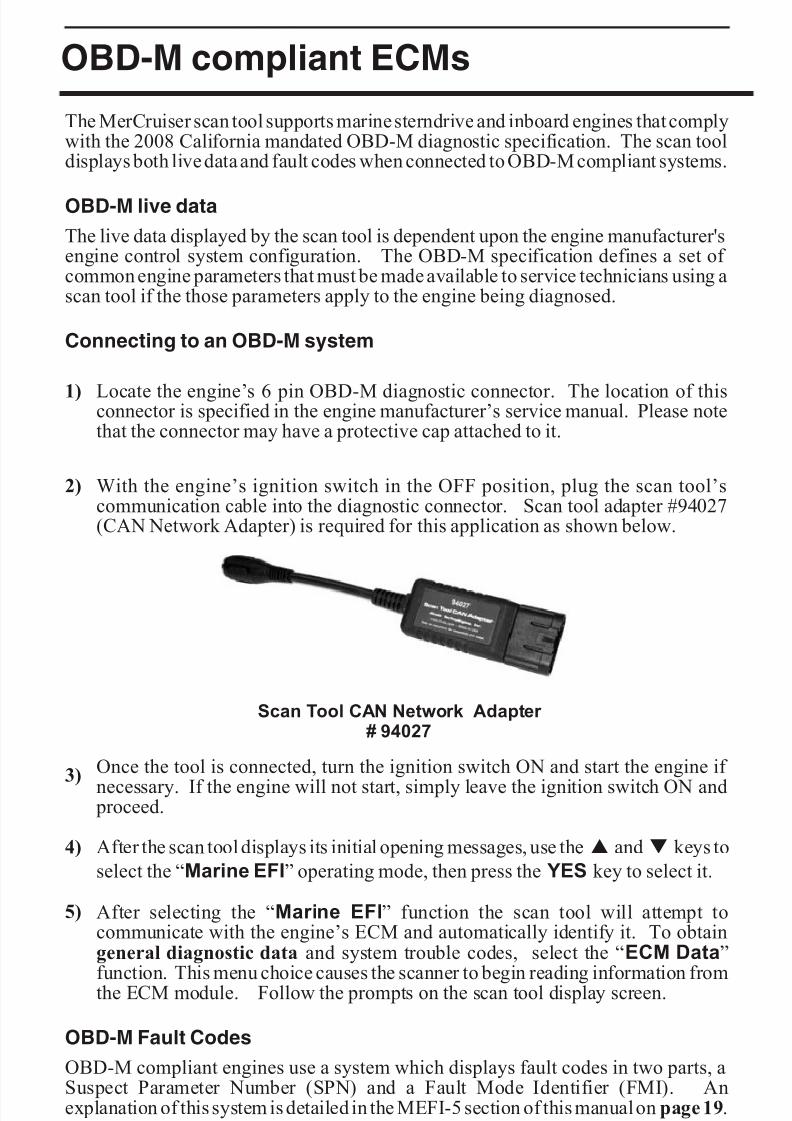
OBD-M compliant ECMs
The MerCruiser scan tool supports marine sterndrive and inboard engines that complywith the 2008 California mandated OBD-M diagnostic specification. The scan tooldisplays both live data and fault codes when connected to OBD-M compliant systems.
OBD-M live data
The live data displayed by the scan tool is dependent upon the engine manufacturer'sengine control system configuration. The OBD-M specification defines a set of common engine parameters that must be made available to service technicians using ascan tool if the those parameters apply to the engine being diagnosed.
Connecting to an OBD-M system
1) Locate the engine’s 6 pin OBD-M diagnostic connector. The location of thisconnector is specified in the engine manufacturer’s service manual. Please notethat the connector may have a protective cap attached to it.
2) With the engine’s ignition switch in the OFF position, plug the scan tool’scommunication cable into the diagnostic connector. Scan tool adapter #94027(CAN Network Adapter) is required for this application as shown below.
3) Once the tool is connected, turn the ignition switch ON and start the engine if
necessary. If the engine will not start, simply leave the ignition switch ON and proceed.
4) After the scan tool displays its initial opening messages, use the s and t keys to
select the “Marine EFI” operating mode, then press the YES key to select it.
5) After selecting the “Marine EFI” function the scan tool will attempt tocommunicate with the engine’s ECM and automatically identify it. To obtaingeneral diagnostic data and system trouble codes, select the “ECM Data”
function. This menu choice causes the scanner to begin reading information fromthe ECM module. Follow the prompts on the scan tool display screen.
OBD-M Fault Codes
OBD-M compliant engines use a system which displays fault codes in two parts, aSuspect Parameter Number (SPN) and a Fault Mode Identifier (FMI). Anexplanation of this system is detailed in the MEFI-5 section of this manual on page 19.
Page 34
Scan Tool CAN Network Adapter # 94027
8/8/2019 Merc Manual v5
http://slidepdf.com/reader/full/merc-manual-v5 39/76
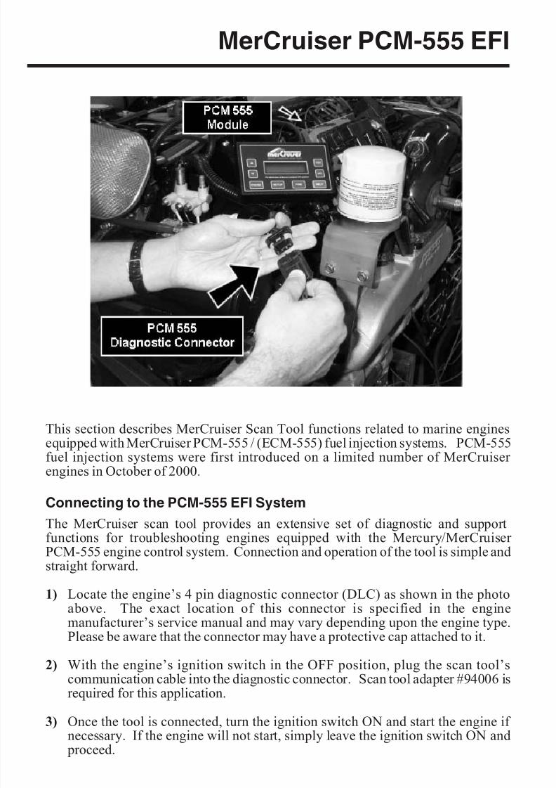
MerCruiser PCM-555 EFI
This section describes MerCruiser Scan Tool functions related to marine enginesequipped with MerCruiser PCM-555 / (ECM-555) fuel injection systems. PCM-555fuel injection systems were first introduced on a limited number of MerCruiser engines in October of 2000.
Connecting to the PCM-555 EFI System
The MerCruiser scan tool provides an extensive set of diagnostic and supportfunctions for troubleshooting engines equipped with the Mercury/MerCruiser
PCM-555 engine control system. Connection and operation of the tool is simple andstraight forward.
1) Locate the engine’s 4 pin diagnostic connector (DLC) as shown in the photoabove. The exact location of this connector is specified in the enginemanufacturer’s service manual and may vary depending upon the engine type.Please be aware that the connector may have a protective cap attached to it.
2) With the engine’s ignition switch in the OFF position, plug the scan tool’scommunication cable into the diagnostic connector. Scan tool adapter #94006 is
required for this application.
3) Once the tool is connected, turn the ignition switch ON and start the engine if necessary. If the engine will not start, simply leave the ignition switch ON and
proceed.
Page 35
8/8/2019 Merc Manual v5
http://slidepdf.com/reader/full/merc-manual-v5 40/76
8/8/2019 Merc Manual v5
http://slidepdf.com/reader/full/merc-manual-v5 41/76
MerCruiser PCM-555 EFI
4) When all faults from the PCM’s Fault Memory have been displayed, the scanner will provide you with the option of reviewing the faults or erasing them. Theerase function will clear the PCM’s “Fault Memory” to eradicate the faults thatwere stored during the present Ignition ON cycle. The faults and associatedsnapshot engine data stored in the PCM’s “Freeze Frame Memory” will not beerased.
5) After the scanner has exited it’s fault access mode the tool will enter its “Scanner”mode. This mode allows you to select and display a wide variety of engine sensor and operating information. The displayed data is updated several times per second. Use the s and t keys to scroll through the available data. Use theHELP key to access information on the currently displayed engine parameter.
Use the NO key to exit the “Scanner” mode and return to the main menu.
Fault History
The PCM-555 control module contains a non-volatile memory that is used to retainfault and operating history information. This information is retained in the PCM evenif power is removed from the system and allows historical operating information to berecalled. This information is designed to aid a technician in diagnosing intermittentand past events. To view “Fault History” information, perform the following steps:
1) After selecting the “Fault History“ function from the scanner’s PCM-555 menuyou will be presented with a sub-menu containing the following choices:
Read Fault Hist
Read Fault Sec
2) Select the “Read Fault Hist” menu item then press YES. The scanner will now
interrogate the PCM’s “Freeze Frame Memory” to determine if any faults haveoccurred in the past. If any faults are found, their descriptions will be displayed.
3) After the scanner displays a fault description it will give you the option to accessthe fault’s associated Freeze Frame engine data. This data represents a snapshotof various engine parameters at the time the fault was detected. Use the s andt keys to recall and scroll through the fault’s Freeze Frame data. After viewingthe Freeze Frame data press NO to return to the Fault History access mode.
Note: While displaying Freeze Frame data a “ ff:” will appear on the left side
of the second line of the scanner’s display.
4) When all faults from the PCM’s Freeze Frame Memory have been displayed thescanner will provide you with the option of reviewing the faults or erasing them.The erase function will clear the PCM’s “Freeze Frame Memory” to eradicatethe PCM’s fault history data . The faults and associated snapshot engine datastored in the PCM’s “Freeze Frame Memory” (including Fault Seconds,described in the next paragraph) will be completely erased.
Page 37
8/8/2019 Merc Manual v5
http://slidepdf.com/reader/full/merc-manual-v5 42/76
MerCruiser PCM-555 EFI
Fault Seconds
When critical faults occur and remain active the PCM-555 keeps track of how many
seconds the fault has persisted during engine operation. The type and number of critical faults this function keeps track of is pre-selected by the engine manufacturer.All PCM-555 faults do not have an associated “Fault Second” counter assigned tothem, only a select number of fault types are kept track of. To view “Fault Seconds”information perform the following steps:
1) After selecting the “Fault History“ function from the scanner’s PCM-555 menuyou will be presented with a sub-menu containing the following choices:
Read Fault HistRead Fault Sec
2) Select the Read Fault Sec menu item then press YES. The scanner will nowread the PCM’s “Fault Second Memory” and display the number of secondseach critical fault has persisted. Use the s and t keys to recall and scrollthrough the Fault Second data. After viewing the Fault Second data, press theNO key to return to the Fault History access mode.
Note: The Fault Second information is erased when the Fault History’s“Freeze Frame Memory” is cleared. See the prior section describing Fault
History for details.
RPM History
PCM-555 control modules have the ability to record the number of hours an enginehas been operated within a predetermined set of RPM ranges. These ranges are set at
the factory and allow a service technician to view a profile of how a particular enginehas been operated. To view “RPM History” information perform the followingsteps:
1) After selecting the “RPM History“ function from the scanner’s PCM-555 menuyou will be presented with a sub-menu containing the following choices:
Read RPM History
Erase RPM Hist
2) Select the Read RPM History menu item then press YES. The scanner willnow read the PCM’s “RPM History Memory” and display the number of hoursthe engine has operated in 9 sets of RPM ranges. Use the s and t keys to scrollthrough the RPM History data. After viewing the RPM History data press the NOkey to return to the RPM History menu.
Page 38
8/8/2019 Merc Manual v5
http://slidepdf.com/reader/full/merc-manual-v5 43/76
MerCruiser PCM-555 EFI
Erase RPM History
This function clears the RPM History memory. The accumulated hours recorded for
each of the nine RPM ranges will be reset to zero after this function is executed.Please note that the Total Operating Hours will not be cleared. This value is noterasable.
PCM System Info
The PCM-555 control module contains an area of memory that is used to store helpfultext information for the service technician. This information consists of many lines of text which describe basic engine settings, capacities, etc, as well as PCM software
revision information. The System Info data is entered into the PCM’s memory at thefactory and may be read by performing the following steps :
1) After selecting the “PCM System Info“ function from the main PCM-555 menuthe scanner will begin to display the first line of System Info text from the PCM’smemory. Use the following keys to navigate through the multiple lines of SystemInfo text information:
Keys to control System Info display:
Use the s key to repeat the line of information currently scrolling across thescanner’s display screen.
Use the t key to skip to the next available line of system information.
Use the PAUSE key to momentarily pause the scrolling display.
Use the NO key to abort the SystemInfo function and return to the main PCM-555scanner menu.
2) After the scanner displays the last line of system information it will automaticallyreturn to the main PCM-555 menu.
Page 39
8/8/2019 Merc Manual v5
http://slidepdf.com/reader/full/merc-manual-v5 44/76
MerCruiser PCM-555 EFI
PCM Functions
The PCM Functions menu option allows a technician to access a variety of PCM
functional tests and settings. To access the PCM Functions menu perform thefollowing steps:
1) After selecting the “PCM Functions“ option from the scanner’s PCM-555menu you will be presented with a sub-menu containing the following choices:
Auto Self Test
Output Tests
Induced MisfireIAC Test
Set Engine Loc
Set Trim Limit
2) Use the s and t keys to select the desired menu item then press YES.
PCM Function - Auto Self Test
The Auto Self Test function is actually a series of individual PCM tests that areexecuted in sequence. These tests are designed to provide a service technician with aquick method of testing engine actuators, ignition coils, fuel injectors and sensors todetermine if they are operating within an acceptable range.
· WARNING: During this test, backfire and external flame canoccur if fuel vapors have not been purged from the engine.
Purge fuel vapors prior to performing this test so they are notignited when the spark plugs are fired. Do not remove the flamearrestor if the engine is equipped with one.
· IMPORTANT: Before performing this test the engine’s electricfuel pump should be disabled. Disabling of the fuel pump maybe accomplished by removing the fuel pump fuse or discon-necting the pump’s electrical connector.
·
The Auto Self Test should be performed with Key-On and EngineOff.
1) Review the warnings stated above and be sure the engine is not running whenattempting to conduct this test. The Auto Self Test should be run with Key-Onand Engine Off .
Page 40
8/8/2019 Merc Manual v5
http://slidepdf.com/reader/full/merc-manual-v5 45/76
MerCruiser PCM-555 EFI
2) After selecting the “Auto Self Test“ function from the PCM Functions menu thescanner will begin to display several warning messages. Review these messagesand be certain their instructions are followed.
3) When the warning messages have been displayed, you may begin the Auto Self Test by pressing the YES key. This action will initiate a series of engine actuator and sensor tests. The entire testing process may take several minutes to complete.While the Auto Self Test is in progress the scanner’s display will indicate the typeof test being performed.
· To Abort the Auto Self Test at any time, press and hold thescanner’s NO key.
4) When the Auto Self Test has completed, the scanner will automaticallyinterrogate the PCM’s fault code memory and report any errors that haveoccurred. A successful self test will report no errors.
PCM Function - Output Tests
The Output Test menu provides a technician with the ability to exercise various PCMactuators and controls in order to verify correct operation.
Available output tests are:
Fuel Injectors
Fuel Pump Relay
Ignition Coils
Warning Horn
Tach Output
The sections presented on the following pages will provide specific details on eachoutput test.
Page 41
8/8/2019 Merc Manual v5
http://slidepdf.com/reader/full/merc-manual-v5 46/76
MerCruiser PCM-555 EFI
Fuel Injector Output Test
The Fuel Injector output test allows individual fuel injectors to be actuated to verify
their operation. The fuel injector under test will be fired at a rate equivalent to 1600rpm. This test helps a technician verify that a particular fuel injector is receiving acommand signal from the PCM. This test will not reveal if an injector is clogged,internally leaking or mechanically worn.
· IMPORTANT: Before performing this test the engine’s electricfuel pump should be disabled. Disabling of the fuel pump maybe accomplished by removing the fuel pump fuse or disconnecting the pump’s electrical connector.
· This test should be performed with Key-On and Engine Off.
1) Review the warnings stated above and be sure the engine is not running whenattempting to perform this test.
2) After selecting the “Fuel Injector “ function from the PCM Output Test menu thescanner will begin to display several warning messages. Review these messagesand be certain their instructions are followed.
3) When the warning messages have been displayed, you may select the fuelinjector you wish to test by using the s and t keys. To begin firing theselected injector press the FIRE key. This action will being actuating the fuelinjector at a speed equivalent to 1600 rpm for a period of approximately 10seconds.
· To abort the Fuel Injector test at any time, press and hold thescanner’s NO key.
4) After the test is complete you may return to step #3 to test another injector or pressthe NO key to return to the scanner’s Output Test menu.
Fuel Pump Relay Output Test
This test will cause the PCM to energize the fuel pump relay thereby activating theengine’s electric fuel pump. Upon executing this test the technician should listen for fuel pump and relay mechanical activity. The relay will be activated for a period of
one second.
· This test should be performed with Key-On and Engine Off.
1) Review the advisory message stated above and be sure the engine is not runningwhen attempting to perform this test.
Page 42
8/8/2019 Merc Manual v5
http://slidepdf.com/reader/full/merc-manual-v5 47/76
MerCruiser PCM-555 EFI
2) After selecting the “Fuel Pump Relay“ test from the PCM Output Test menuthe scanner will prompt you to begin the test. To initiate the test press the FIREkey. The fuel pump relay will be activated for approximately one second.
3) You may press the FIRE key again to repeat the test or press the NO key to returnto the Output Test menu.
Ignition Coil Output Test
The Ignition Coil output test allows individual coils and their associated spark outputsto be fired to verify their operation. This test requires that a spark gap tester be usedto verify proper ignition coil operation. The ignition coil under test will be fired at arate equivalent to 1600 rpm. This test helps a technician verify that a particular ignition coil is receiving a command signal from the PCM and that the coil’s highvoltage output is sufficient to generate a spark discharge.
· WARNING: Use of spark gap tester is required for this test. Donot perform this test with the ignition wires attached to theengine’s spark plugs while they are installed in the cylinders.Engine backfire and external flame can occur. As a safetyprecaution, purge fuel vapors from the engine before
proceeding.· An approved spark gap tester must be attached to the spark
output under test. See the spark gap tester’s instructions for proper installation, adjustment and use.
· IMPORTANT: Before performing this test the engine’s electricfuel pump should be disabled. Disabling of the fuel pump maybe accomplished by removing the fuel pump fuse or disconnecting the pump’s electrical connector.
· This test should be performed with Key-On and Engine Off.
1) Review the warnings stated above and be sure the engine is not running whenattempting to perform this test.
2) After selecting the “Ignition Coil“ function from the PCM Output Test menu thescanner will begin to display several warning messages. Review these messages
and be certain their instructions are followed.
Page 43
8/8/2019 Merc Manual v5
http://slidepdf.com/reader/full/merc-manual-v5 48/76
MerCruiser PCM-555 EFI
3) When the warning messages have been displayed, you may select the ignition coilyou wish to test by using the s and t keys. To begin firing the selected coil press the FIRE key. This action will begin firing the ignition coil at a speedequivalent to 1600 rpm for a period of approximately 10 seconds.
· To abort the Ignition Coil test at any time, press and hold thescanner’s NO key.
4) After the test is complete you may return to step #3 to test another ignition coil or press the NO key to return to the scanner’s Output Test menu.
Warning Horn Output Test
This test will cause the PCM to energize the engine warning horn. Upon executingthis test the technician should listen for warning horn activity. The warning horn will
be activated for a period of one second.
· This test should be performed with Key-On and Engine Off.
1) Review the advisory message stated above and be sure the engine is not runningwhen attempting to perform this test.
2) After selecting the “Warning Horn“ test from the PCM Output Test menu thescanner will prompt you to begin the test To initiate the test press the FIRE key.The warning horn will be activated for approximately one second.
3) You may press the FIRE key again to repeat the test or press the NO key to returnto the Output Test menu.
Tachometer Output Test
The Tachometer Output test is primarily used to verify the operation of an external,dash mounted, engine tachometer. The PCM is capable of supplying an internallygenerated RPM signal to a tachometer gauge during engine operation. This test willcommand the PCM to output a tach signal that is equivalent to 3000 rpm.
· This test should be performed with Key-On and Engine Off.
1) Review the advisory message stated above and be sure the engine is not runningwhen attempting to perform this test.
Page 44

8/8/2019 Merc Manual v5
http://slidepdf.com/reader/full/merc-manual-v5 49/76
MerCruiser PCM-555 EFI
2) After selecting the “Tach Output“ test from the PCM Output Test menu thescanner will prompt you to begin the test. To initiate the test press the FIRE key.The tachometer output will begin sending a signal equivalent to 3000 rpm to anexternally attached (usually dashboard mounted) tachometer gauge. The tachsignal will be active for approximately 10 seconds.
3) You may press the FIRE key again to repeat the test or press the NO key to returnto the Output Test menu.
PCM Function - IAC Test
The IAC Test allows the functionality of the engine’s Idle Air Control system to betested. This test commands the PCM module to change the IAC valve’s positionthereby changing the engine’s idle speed. Perform the following steps to conduct theIAC test.
· IMPORTANT: This test should be performed in Neutral with theengine idling and at normal operating temperature.
· Do not attempt to drive the boat while performing this test.
· Follow all engine and boat manufacturer’s safety precautionsand stay clear of all moving engine components.
1) Review the warnings stated above prior to conducting this test. For best resultsthe engine should be idling at normal operating temperature.
2) After selecting the “IAC Test“ function from the PCM Functions menu thescanner will begin to display one or more advisory messages. Review thesemessages and be certain their instructions are followed.
3) When the advisory messages have been displayed, you may begin the test by pressing the YES key. While the test is in progress the scanner will display thecurrent engine RPM as well as the IAC valve’s position. Use the s and t keysto change the IAC’s position in 10% increments. The IAC position range is from-100% to +100%. While changing the IAC position you should hear a noticeablechange in engine speed.
4) To exit the IAC test, press the NO key. You will be returned to the scanner’s PCMFunction menu.
Page 45
8/8/2019 Merc Manual v5
http://slidepdf.com/reader/full/merc-manual-v5 50/76
MerCruiser PCM-555 EFI
PCM Function - Set Engine Location
This function allows the technician to read and modify the PCM’s engine location
setting. All engines shipped from the factory are configured as STARBOARD.Multi-engine installations may require an alternate setting when used within aMercury/MerCruiser SmartCraft system. Refer to the engine and boat manufacturer’sinstallation procedures for the correct setting.
Available PCM engine location settings are as follows:
STARBOARD
PORT
STARBRD 2 INSIDE
PORT 2 INSIDE
Perform the following steps to read and change the Engine Location.
· This test should be performed with Key-On and Engine Off.
1) Review the advisory message stated above prior to performing this function.
2) After selecting the “Set Engine Loc“ function from the PCM Functions menuthe scanner will automatically read and display the current Engine Locationsetting. After displaying the setting you may choose to proceed to alter thelocation setting by pressing the YES key. Use the s and t keys to scrollthrough the available location settings.
3) When you have selected the correct Engine Location Setting, press the YES keyto make the new setting permanent. The scanner will program the new locationsetting into the PCM’s memory and you will be returned to the scanner’s PCMFunction menu.
Note: The new Engine Location setting will not become active until theignition has been cycled OFF and then back ON.
PCM Function - Induced Misfire Test
The Induced Misfire Test is designed to assist a technician in finding a problematic
cylinder. This test commands the PCM module to disable the fuel injector on aselected cylinder thereby causing that cylinder to misfire (not produce power).Perform the following steps to conduct the induced misfire test.
· IMPORTANT: This test should be performed with the enginerunning at approximately 1500 rpm, at normal operatingtemperature and under moderate load.
Page 46
8/8/2019 Merc Manual v5
http://slidepdf.com/reader/full/merc-manual-v5 51/76
MerCruiser PCM-555 EFI
· Do not attempt to drive the boat while performing this test.
· Follow all engine and boat manufacturer’s safety precautionsand stay clear of all moving engine components.
1) Review the warnings stated above prior to conducting this test. For best resultsthe engine should be running at approx. 1500 rpm and under a moderate load.
2) After selecting the “Induced Misfire” function from the PCM Functions menuthe scanner will begin to display one or more advisory messages. Review thesemessages and be certain their instructions are followed.
3) When the advisory messages have been displayed, you may select the cylinder you wish to disable by using the s and t keys. To begin the test press theFIRE key. This action will command the PCM to disable the fuel injector on theselected cylinder for approximately 10 seconds. During this time you should hear a noticeable decrease in engine speed. This decrease indicates that the selectedcylinder was contributing power to the system.
If a decrease in engine speed is not heard during the course of this test it mayindicate a problem with one or more cylinder components including the fuelinjector, ignition coil, spark plug, or other component. Refer to the enginemanufacturer’s troubleshooting procedures to isolate the problem component.
· To Abort the Induced Misfire Test at any time, press and holdthe scanner’s NO key.
4) After the test is complete you may return to step #3 to test another cylinder or pressthe NO key to return to the scanner’s PCM Function menu.
PCM Function - Set Trim Limit
The Trim Limit Setpoint function allows the technician to limit the range of the sterndrive’s trim movement. This setting has a range of 0% to 100%. When the trim
position reaches the Trim Limit Setpoint the PCM will disable the trim limit relay inorder to restrain the stern drive mechanism from further advancement. Perform thefollowing steps to read and change the Trim Limit Setpoint.
· This test should be performed with Key-On and Engine Off.
1) Review the advisory message stated above prior to performing this function.
2) After selecting the “Set Trim Limit“ function from the PCM Functions menu thescanner will display the current Trim Limit setting.
Page 47
8/8/2019 Merc Manual v5
http://slidepdf.com/reader/full/merc-manual-v5 52/76
MerCruiser PCM-555 EFI
3) After displaying the current setting you may choose to alter the setpoint by pressing the YES key. Use the s and t keys to change the setpoint in 1%increments. The Trim Limit Setpoint range is from 0% to 100%. You may pressthe NO key at any time to abort the Trim Limit setpoint procedure.
4) To make the currently displayed setpoint permanent press the YES key. Thescanner will program the new setpoint into the PCM’s memory and you will bereturned to the scanner’s PCM Function menu.
PCM Function - Set Trailer Limit
Similar to the Set Trim Limit function described above, some MerCruiser systemsallow the trailering position of the sterndrive to be set. This position is above the TrimLimit setpoint and is the upper limit of the sterndrive for trailering situations. Followthe scan tool's on screen prompts to set the Trailer Limit.
PCM Function - Gear Shift Motor Test (DTS systems only)
This test allows the technician to test the functionality sterndrive's shift actuator mechanism by commanding it to move into the Forward and Reverse positions.
· WARNING: This test causes the vessel's sterndrive to shift into
forward and reverse, thereby causing the vessel to move.
· This test must be performed in NEUTRAL with the engineIDLING.
· Refer to the engine manufacturer's safety instructions PRIOR toperforming this test.
· Vessel should be secured to prevent movement.
After referring to the manufacturer's instructions and safety procedures for this procedure, follow the scan tool's on screen prompts to proceed with the test.
Press and hold the NO key on the scan tool's keypad to stop the test at any time.
PCM Function - Throttle Motor Test (DTS systems only)
This test allows a technician to check the functionality of the engine's electronicthrottle actuator motor. The test allows the throttle blade to be moved in 5 degreeincrements using the scan tool's s and t keys and also displays the current TPSvoltages in real-time.
· This test must be performed with Key-On, Engine Off
Follow the scan tool's on screen prompts to proceed with the test.
Press and hold the NO key on the scan tool's keypad to stop the test at any time.
Page 48
8/8/2019 Merc Manual v5
http://slidepdf.com/reader/full/merc-manual-v5 53/76
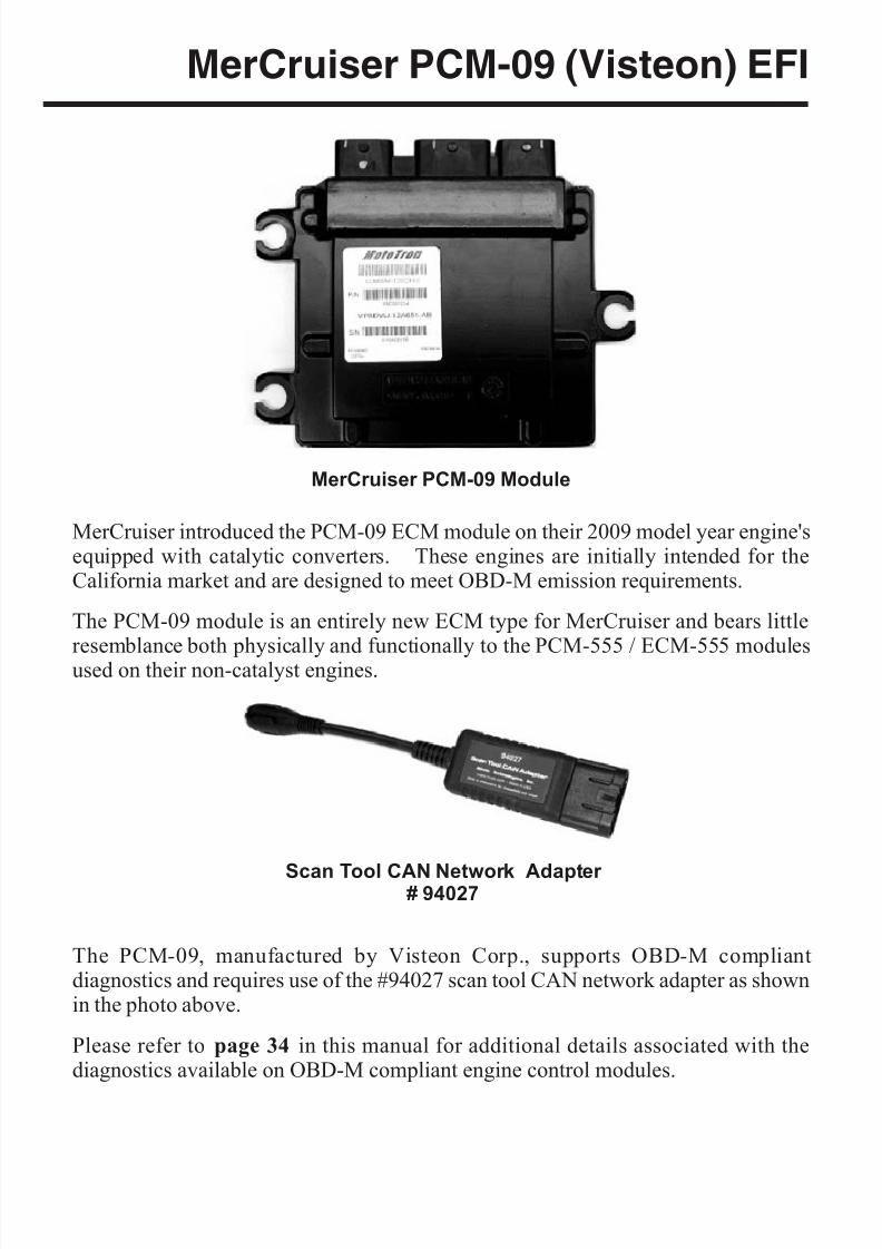
MerCruiser PCM-09 (Visteon) EFI
MerCruiser introduced the PCM-09 ECM module on their 2009 model year engine'sequipped with catalytic converters. These engines are initially intended for theCalifornia market and are designed to meet OBD-M emission requirements.
The PCM-09 module is an entirely new ECM type for MerCruiser and bears little
resemblance both physically and functionally to the PCM-555 / ECM-555 modulesused on their non-catalyst engines.
The PCM-09, manufactured by Visteon Corp., supports OBD-M compliantdiagnostics and requires use of the #94027 scan tool CAN network adapter as shownin the photo above.
Please refer to page 34 in this manual for additional details associated with thediagnostics available on OBD-M compliant engine control modules.
Page 49
Scan Tool CAN Network Adapter # 94027
MerCruiser PCM-09 Module
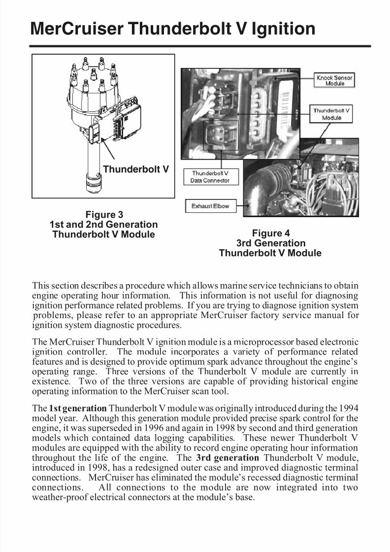
8/8/2019 Merc Manual v5
http://slidepdf.com/reader/full/merc-manual-v5 54/76
MerCruiser Thunderbolt V Ignition
This section describes a procedure which allows marine service technicians to obtainengine operating hour information. This information is not useful for diagnosingignition performance related problems. If you are trying to diagnose ignition system
problems, please refer to an appropriate MerCruiser factory service manual for ignition system diagnostic procedures.
The MerCruiser Thunderbolt V ignition module is a microprocessor based electronicignition controller. The module incorporates a variety of performance relatedfeatures and is designed to provide optimum spark advance throughout the engine’soperating range. Three versions of the Thunderbolt V module are currently inexistence. Two of the three versions are capable of providing historical engineoperating information to the MerCruiser scan tool.
The 1st generation Thunderbolt V module was originally introduced during the 1994model year. Although this generation module provided precise spark control for theengine, it was superseded in 1996 and again in 1998 by second and third generationmodels which contained data logging capabilities. These newer Thunderbolt Vmodules are equipped with the ability to record engine operating hour informationthroughout the life of the engine. The 3rd generation Thunderbolt V module,introduced in 1998, has a redesigned outer case and improved diagnostic terminalconnections. MerCruiser has eliminated the module’s recessed diagnostic terminalconnections. All connections to the module are now integrated into twoweather-proof electrical connectors at the module’s base.
Page 50
Figure 43rd Generation
Thunderbolt V Module
Figure 31st and 2nd GenerationThunderbolt V Module
Thunderbolt V
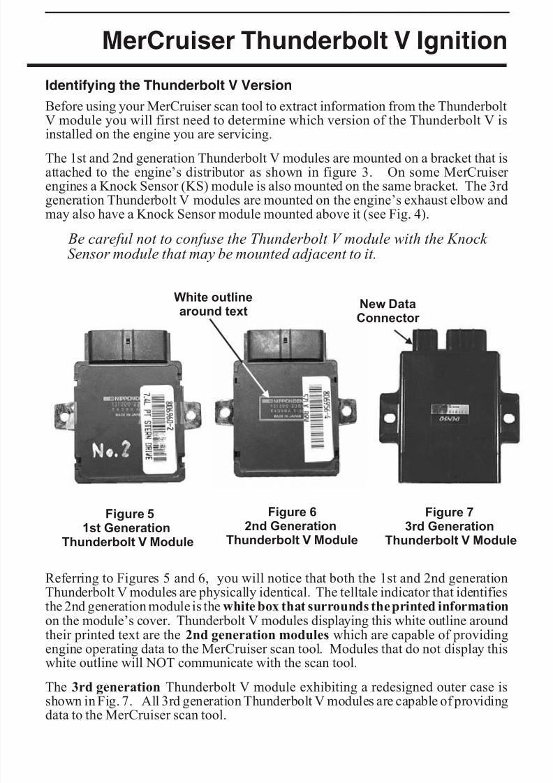
8/8/2019 Merc Manual v5
http://slidepdf.com/reader/full/merc-manual-v5 55/76
MerCruiser Thunderbolt V Ignition
Identifying the Thunderbolt V Version
Before using your MerCruiser scan tool to extract information from the ThunderboltV module you will first need to determine which version of the Thunderbolt V is
installed on the engine you are servicing.The 1st and 2nd generation Thunderbolt V modules are mounted on a bracket that isattached to the engine’s distributor as shown in figure 3. On some MerCruiser engines a Knock Sensor (KS) module is also mounted on the same bracket. The 3rdgeneration Thunderbolt V modules are mounted on the engine’s exhaust elbow andmay also have a Knock Sensor module mounted above it (see Fig. 4).
Be careful not to confuse the Thunderbolt V module with the Knock Sensor module that may be mounted adjacent to it.
Referring to Figures 5 and 6, you will notice that both the 1st and 2nd generationThunderbolt V modules are physically identical. The telltale indicator that identifiesthe 2nd generation module is the white box that surrounds the printed informationon the module’s cover. Thunderbolt V modules displaying this white outline aroundtheir printed text are the 2nd generation modules which are capable of providingengine operating data to the MerCruiser scan tool. Modules that do not display thiswhite outline will NOT communicate with the scan tool.
The 3rd generation Thunderbolt V module exhibiting a redesigned outer case isshown in Fig. 7. All 3rd generation Thunderbolt V modules are capable of providingdata to the MerCruiser scan tool.
Page 51
Figure 73rd Generation
Thunderbolt V Module
Figure 62nd Generation
Thunderbolt V Module
White outlinearound text
New DataConnector
Figure 51st Generation
Thunderbolt V Module
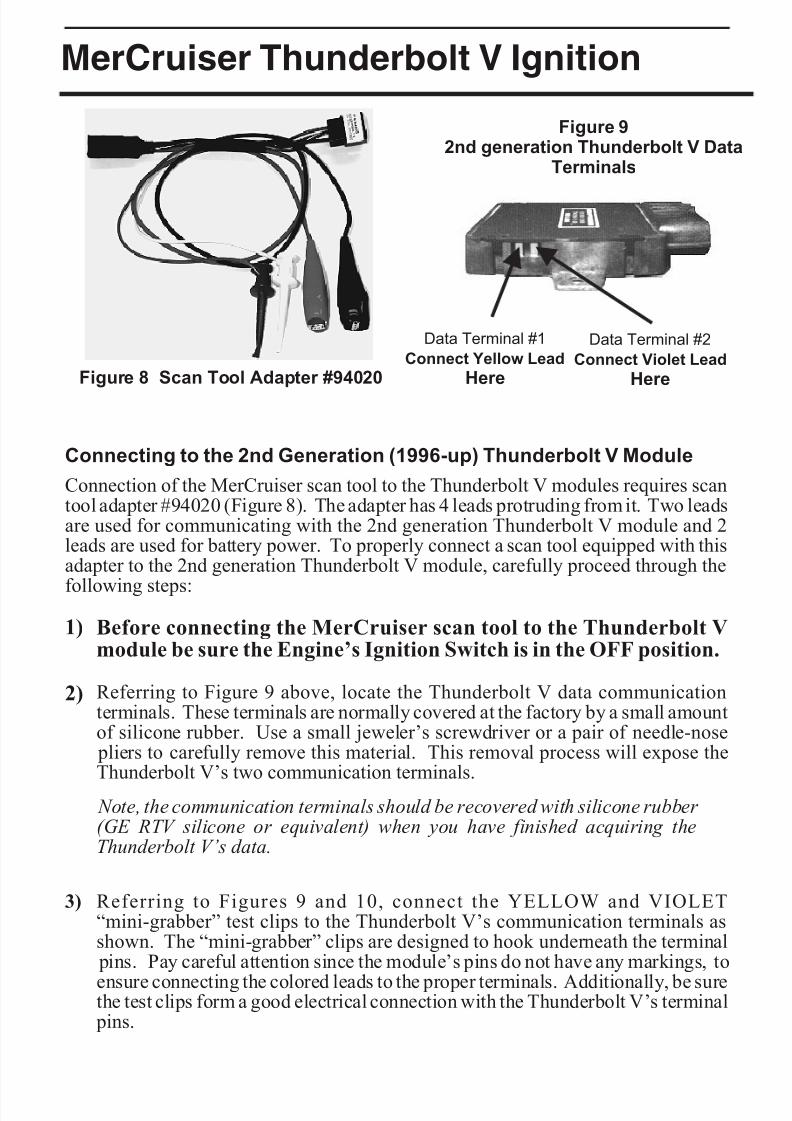
8/8/2019 Merc Manual v5
http://slidepdf.com/reader/full/merc-manual-v5 56/76
MerCruiser Thunderbolt V Ignition
Connecting to the 2nd Generation (1996-up) Thunderbolt V Module
Connection of the MerCruiser scan tool to the Thunderbolt V modules requires scantool adapter #94020 (Figure 8). The adapter has 4 leads protruding from it. Two leadsare used for communicating with the 2nd generation Thunderbolt V module and 2leads are used for battery power. To properly connect a scan tool equipped with thisadapter to the 2nd generation Thunderbolt V module, carefully proceed through the
following steps:
1) Before connecting the MerCruiser scan tool to the Thunderbolt Vmodule be sure the Engine’s Ignition Switch is in the OFF position.
2) Referring to Figure 9 above, locate the Thunderbolt V data communicationterminals. These terminals are normally covered at the factory by a small amountof silicone rubber. Use a small jeweler’s screwdriver or a pair of needle-nose
pliers to carefully remove this material. This removal process will expose theThunderbolt V’s two communication terminals.
Note, the communication terminals should be recovered with silicone rubber (GE RTV silicone or equivalent) when you have finished acquiring theThunderbolt V’s data.
3) Referring to Figures 9 and 10, connect the YELLOW and VIOLET“mini-grabber” test clips to the Thunderbolt V’s communication terminals asshown. The “mini-grabber” clips are designed to hook underneath the terminal
pins. Pay careful attention since the module’s pins do not have any markings, to
ensure connecting the colored leads to the proper terminals. Additionally, be surethe test clips form a good electrical connection with the Thunderbolt V’s terminal
pins.
Page 52
Data Terminal #1
Connect Yellow Lead
Here
Data Terminal #2
Connect Violet Lead
Here
Figure 92nd generation Thunderbolt V Data
Terminals
Figure 8 Scan Tool Adapter #94020
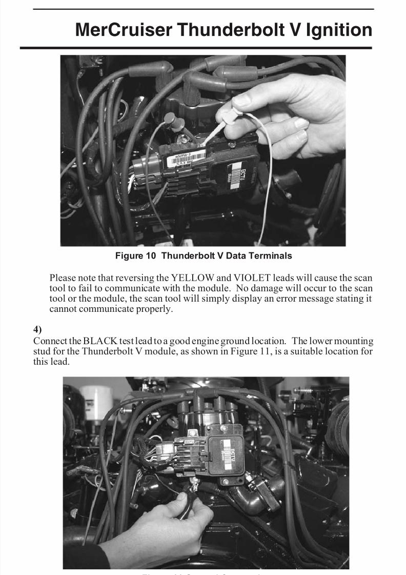
8/8/2019 Merc Manual v5
http://slidepdf.com/reader/full/merc-manual-v5 57/76
MerCruiser Thunderbolt V Ignition
Please note that reversing the YELLOW and VIOLET leads will cause the scantool to fail to communicate with the module. No damage will occur to the scan
tool or the module, the scan tool will simply display an error message stating itcannot communicate properly.
4)
Connect the BLACK test lead to a good engine ground location. The lower mountingstud for the Thunderbolt V module, as shown in Figure 11, is a suitable location for this lead.
Page 53
Figure 11 Ground Connection
Figure 10 Thunderbolt V Data Terminals
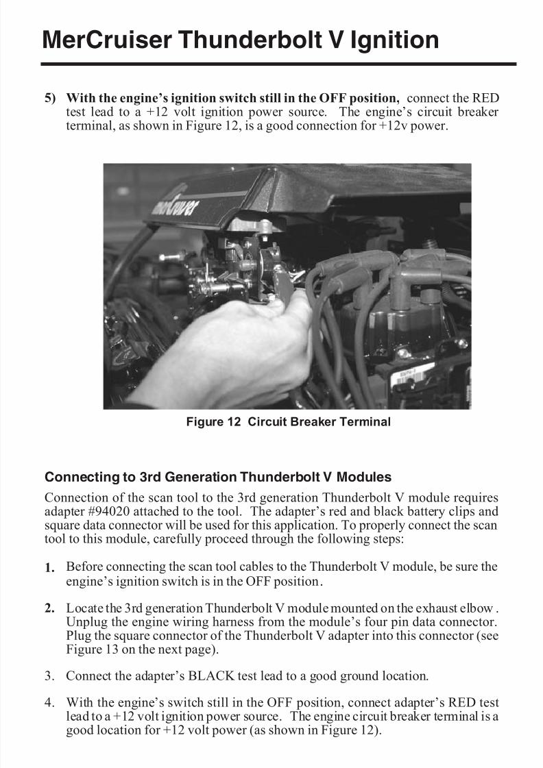
8/8/2019 Merc Manual v5
http://slidepdf.com/reader/full/merc-manual-v5 58/76
MerCruiser Thunderbolt V Ignition
5) With the engine’s ignition switch still in the OFF position, connect the REDtest lead to a +12 volt ignition power source. The engine’s circuit breaker terminal, as shown in Figure 12, is a good connection for +12v power.
Connecting to 3rd Generation Thunderbolt V Modules
Connection of the scan tool to the 3rd generation Thunderbolt V module requiresadapter #94020 attached to the tool. The adapter’s red and black battery clips andsquare data connector will be used for this application. To properly connect the scan
tool to this module, carefully proceed through the following steps:
1. Before connecting the scan tool cables to the Thunderbolt V module, be sure theengine’s ignition switch is in the OFF position.
2. Locate the 3rd generation Thunderbolt V module mounted on the exhaust elbow .Unplug the engine wiring harness from the module’s four pin data connector.Plug the square connector of the Thunderbolt V adapter into this connector (seeFigure 13 on the next page).
3. Connect the adapter’s BLACK test lead to a good ground location.
4. With the engine’s switch still in the OFF position, connect adapter’s RED testlead to a +12 volt ignition power source. The engine circuit breaker terminal is agood location for +12 volt power (as shown in Figure 12).
Page 54
Figure 12 Circuit Breaker Terminal
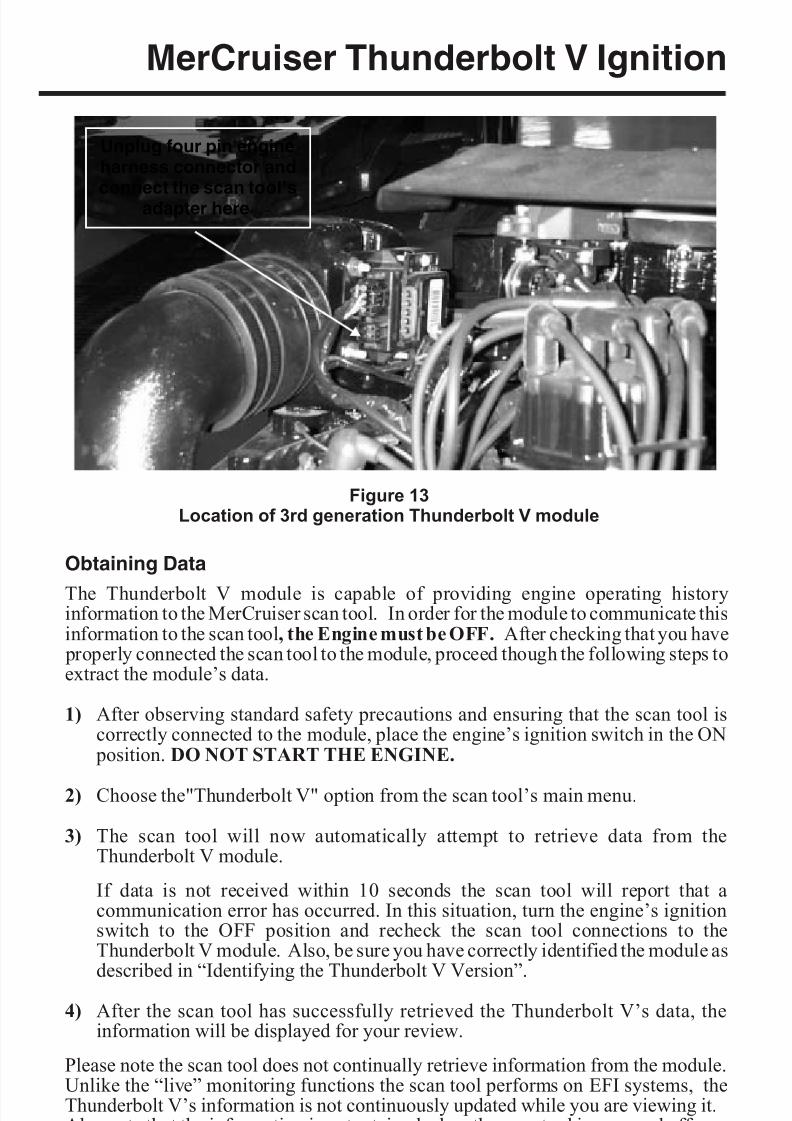
8/8/2019 Merc Manual v5
http://slidepdf.com/reader/full/merc-manual-v5 59/76
MerCruiser Thunderbolt V Ignition
Obtaining Data
The Thunderbolt V module is capable of providing engine operating historyinformation to the MerCruiser scan tool. In order for the module to communicate thisinformation to the scan tool, the Engine must be OFF. After checking that you have
properly connected the scan tool to the module, proceed though the following steps toextract the module’s data.
1) After observing standard safety precautions and ensuring that the scan tool iscorrectly connected to the module, place the engine’s ignition switch in the ON
position. DO NOT START THE ENGINE.
2) Choose the"Thunderbolt V" option from the scan tool’s main menu.
3) The scan tool will now automatically attempt to retrieve data from theThunderbolt V module.
If data is not received within 10 seconds the scan tool will report that acommunication error has occurred. In this situation, turn the engine’s ignitionswitch to the OFF position and recheck the scan tool connections to theThunderbolt V module. Also, be sure you have correctly identified the module asdescribed in “Identifying the Thunderbolt V Version”.
4) After the scan tool has successfully retrieved the Thunderbolt V’s data, theinformation will be displayed for your review.
Please note the scan tool does not continually retrieve information from the module.Unlike the “live” monitoring functions the scan tool performs on EFI systems, theThunderbolt V’s information is not continuously updated while you are viewing it.Also note that the information is not retained when the scan tool is powered off.
Page 55
Unplug four pin engineharness connector and
connect the scan tool’sadapter here
Figure 13Location of 3rd generation Thunderbolt V module
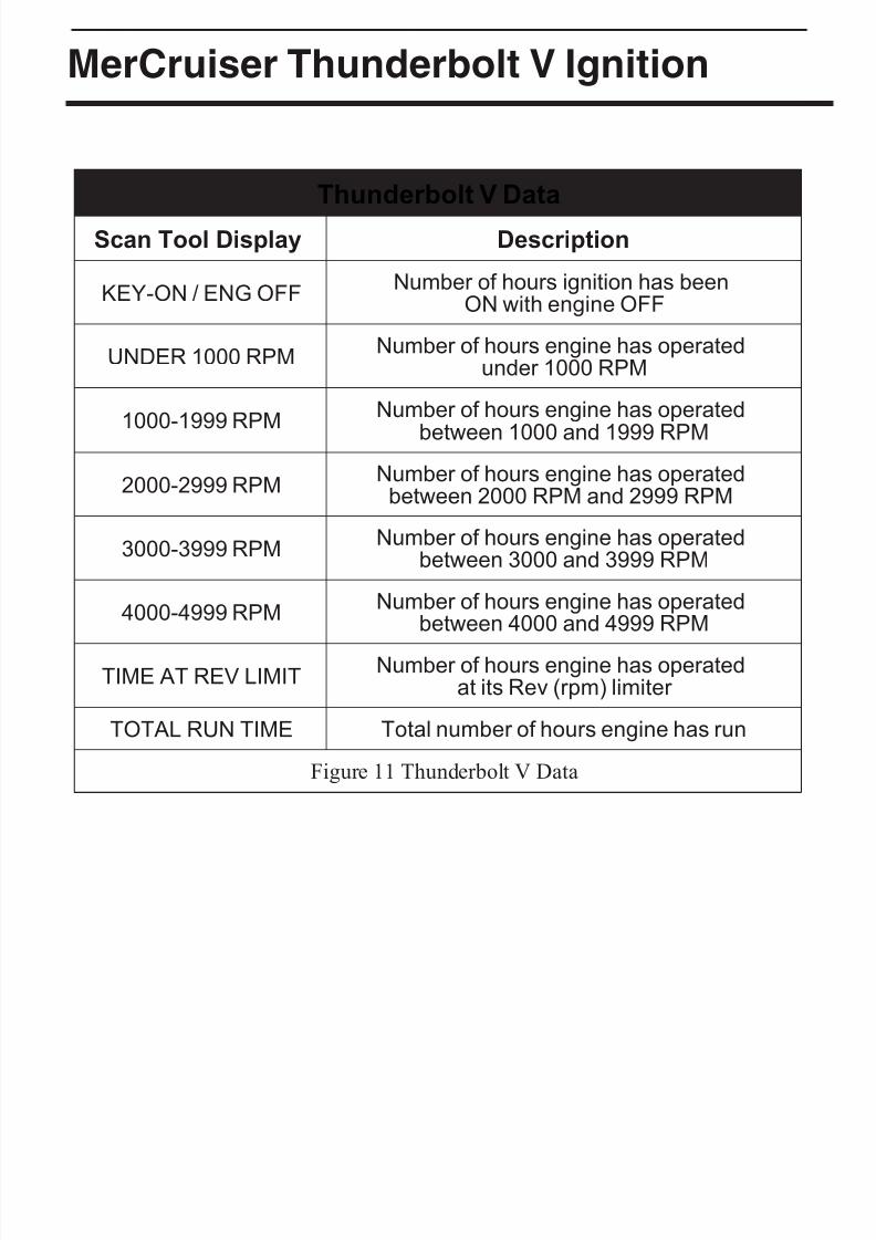
8/8/2019 Merc Manual v5
http://slidepdf.com/reader/full/merc-manual-v5 60/76
MerCruiser Thunderbolt V Ignition
Thunderbolt V Data
Scan Tool Display Description
KEY-ON / ENG OFFNumber of hours ignition has been
ON with engine OFF
UNDER 1000 RPMNumber of hours engine has operated
under 1000 RPM
1000-1999 RPMNumber of hours engine has operated
between 1000 and 1999 RPM
2000-2999 RPMNumber of hours engine has operated
between 2000 RPM and 2999 RPM
3000-3999 RPMNumber of hours engine has operated
between 3000 and 3999 RPM
4000-4999 RPMNumber of hours engine has operated
between 4000 and 4999 RPM
TIME AT REV LIMITNumber of hours engine has operated
at its Rev (rpm) limiter
TOTAL RUN TIME Total number of hours engine has run
Figure 11 Thunderbolt V Data
Page 56

8/8/2019 Merc Manual v5
http://slidepdf.com/reader/full/merc-manual-v5 61/76
MerCruiser Thunderbolt V Ignition
Disconnecting from the Thunderbolt V Modules
Use the following procedure to disconnect the scan tool from all Thunderbolt Vmodules.
1) Turn the engine’s ignition switch to the OFF position.
2) Remove the RED power lead from the +12v power connection.
3) Remove the BLACK ground lead from the engine’s ground connection.
4) For 2nd Generation modules, remove the YELLOW and VIOLET“mini-grabber” test clips from the Thunderbolt V’s communication terminals.For 3rd generation modules unplug the 4 pin scan tool adapter from the module’s
data connector.
5) Replace the removed silicone rubber waterproofing on the 2nd generationmodule’s communication terminals. Use General Electric RTV silicone rubber or equivalent.
6) On 3rd generation modules, replace the four pin engine harness connector.
Page 57
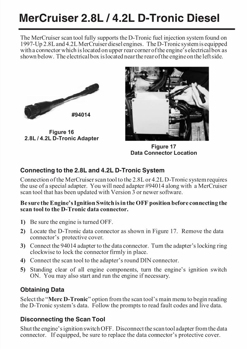
8/8/2019 Merc Manual v5
http://slidepdf.com/reader/full/merc-manual-v5 62/76
MerCruiser 2.8L / 4.2L D-Tronic Diesel
The MerCruiser scan tool fully supports the D-Tronic fuel injection system found on1997-Up 2.8L and 4.2L MerCruiser diesel engines. The D-Tronic system is equippedwith a connector which is located on upper rear corner of the engine’s electrical box asshown below. The electrical box is located near the rear of the engine on the left side.
Connecting to the 2.8L and 4.2L D-Tronic System
Connection of the MerCruiser scan tool to the 2.8L or 4.2L D-Tronic system requiresthe use of a special adapter. You will need adapter #94014 along with a MerCruiser scan tool that has been updated with Version 3 or newer software.
Be sure the Engine’s Ignition Switch is in the OFF position before connecting thescan tool to the D-Tronic data connector.
1) Be sure the engine is turned OFF.
2) Locate the D-Tronic data connector as shown in Figure 17. Remove the dataconnector’s protective cover.
3) Connect the 94014 adapter to the data connector. Turn the adapter’s locking ringclockwise to lock the connector firmly in place.
4) Connect the scan tool to the adapter’s round DIN connector.
5) Standing clear of all engine components, turn the engine’s ignition switchON. You may also start and run the engine if necessary.
Obtaining Data
Select the “Merc D-Tronic” option from the scan tool’s main menu to begin reading
the D-Tronic system’s data. Follow the prompts to read fault codes and live data.
Disconnecting the Scan Tool
Shut the engine’s ignition switch OFF. Disconnect the scan tool adapter from the dataconnector. If equipped, be sure to replace the data connector’s protective cover.
Page 58
Figure 162.8L / 4.2L D-Tronic Adapter
#94014
Figure 17Data Connector Location
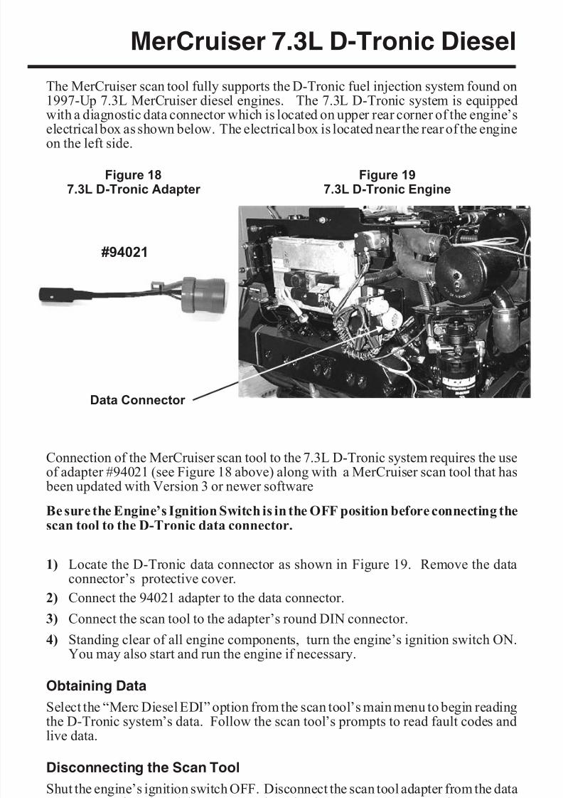
8/8/2019 Merc Manual v5
http://slidepdf.com/reader/full/merc-manual-v5 63/76
MerCruiser 7.3L D-Tronic Diesel
The MerCruiser scan tool fully supports the D-Tronic fuel injection system found on1997-Up 7.3L MerCruiser diesel engines. The 7.3L D-Tronic system is equippedwith a diagnostic data connector which is located on upper rear corner of the engine’selectrical box as shown below. The electrical box is located near the rear of the engine
on the left side.
Connection of the MerCruiser scan tool to the 7.3L D-Tronic system requires the useof adapter #94021 (see Figure 18 above) along with a MerCruiser scan tool that has
been updated with Version 3 or newer software
Be sure the Engine’s Ignition Switch is in the OFF position before connecting thescan tool to the D-Tronic data connector.
1) Locate the D-Tronic data connector as shown in Figure 19. Remove the dataconnector’s protective cover.
2) Connect the 94021 adapter to the data connector.
3) Connect the scan tool to the adapter’s round DIN connector.
4) Standing clear of all engine components, turn the engine’s ignition switch ON.You may also start and run the engine if necessary.
Obtaining Data
Select the “Merc Diesel EDI” option from the scan tool’s main menu to begin readingthe D-Tronic system’s data. Follow the scan tool’s prompts to read fault codes andlive data.
Disconnecting the Scan Tool
Shut the engine’s ignition switch OFF. Disconnect the scan tool adapter from the dataconnector. If equipped, be sure to replace the data connector’s protective cover.
Page 59
Figure 197.3L D-Tronic Engine
#94021
Data Connector
Figure 187.3L D-Tronic Adapter
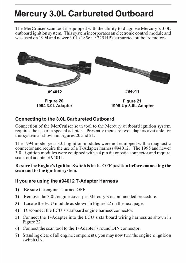
8/8/2019 Merc Manual v5
http://slidepdf.com/reader/full/merc-manual-v5 64/76
Mercury 3.0L Carbureted Outboard
The MerCruiser scan tool is equipped with the ability to diagnose Mercury’s 3.0Loutboard ignition system. This system incorporates an electronic control module andwas used on 1994 and newer 3.0L (185c.i. / 225 HP) carbureted outboard motors.
Connecting to the 3.0L Carbureted Outboard
Connection of the MerCruiser scan tool to the Mercury outboard ignition systemrequires the use of a special adapter. Presently there are two adapters available for this system as shown in Figures 20 and 21.
The 1994 model year 3.0L ignition modules were not equipped with a diagnosticconnector and require the use of a T-Adapter harness #94012. The 1995 and newer 3.0L ignition modules were equipped with a 4 pin diagnostic connector and requirescan tool adapter # 94011.
Be sure the Engine’s Ignition Switch is in the OFF position before connecting thescan tool to the ignition system.
If you are using the #94012 T-Adapter Harness
1) Be sure the engine is turned OFF.
2) Remove the 3.0L engine cover per Mercury’s recommended procedure.
3) Locate the ECU module as shown in Figure 22 on the next page.
4) Disconnect the ECU’s starboard engine harness connector.
5) Connect the T-Adapter into the ECU’s starboard wiring harness as shown inFigure 22.
6) Connect the scan tool to the T-Adapter’s round DIN connector.7) Standing clear of all engine components, you may now turn the engine’s ignition
switch ON.
Page 60
Figure 211995-Up 3.0L Adapter
#94011
Figure 201994 3.0L Adapter
#94012
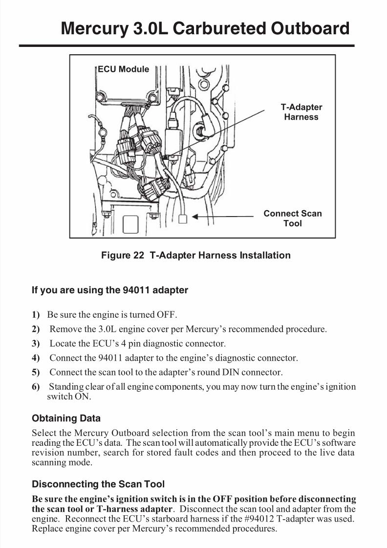
8/8/2019 Merc Manual v5
http://slidepdf.com/reader/full/merc-manual-v5 65/76
Mercury 3.0L Carbureted Outboard
If you are using the 94011 adapter
1) Be sure the engine is turned OFF.
2) Remove the 3.0L engine cover per Mercury’s recommended procedure.
3) Locate the ECU’s 4 pin diagnostic connector.
4) Connect the 94011 adapter to the engine’s diagnostic connector.
5) Connect the scan tool to the adapter’s round DIN connector.
6) Standing clear of all engine components, you may now turn the engine’s ignitionswitch ON.
Obtaining Data
Select the Mercury Outboard selection from the scan tool’s main menu to beginreading the ECU’s data. The scan tool will automatically provide the ECU’s softwarerevision number, search for stored fault codes and then proceed to the live datascanning mode.
Disconnecting the Scan Tool
Be sure the engine’s ignition switch is in the OFF position before disconnectingthe scan tool or T-harness adapter. Disconnect the scan tool and adapter from theengine. Reconnect the ECU’s starboard harness if the #94012 T-adapter was used.Replace engine cover per Mercury’s recommended procedures.
Page 61
Figure 22 T-Adapter Harness Installation
Connect ScanTool
T-Adapter Harness
ECU Module
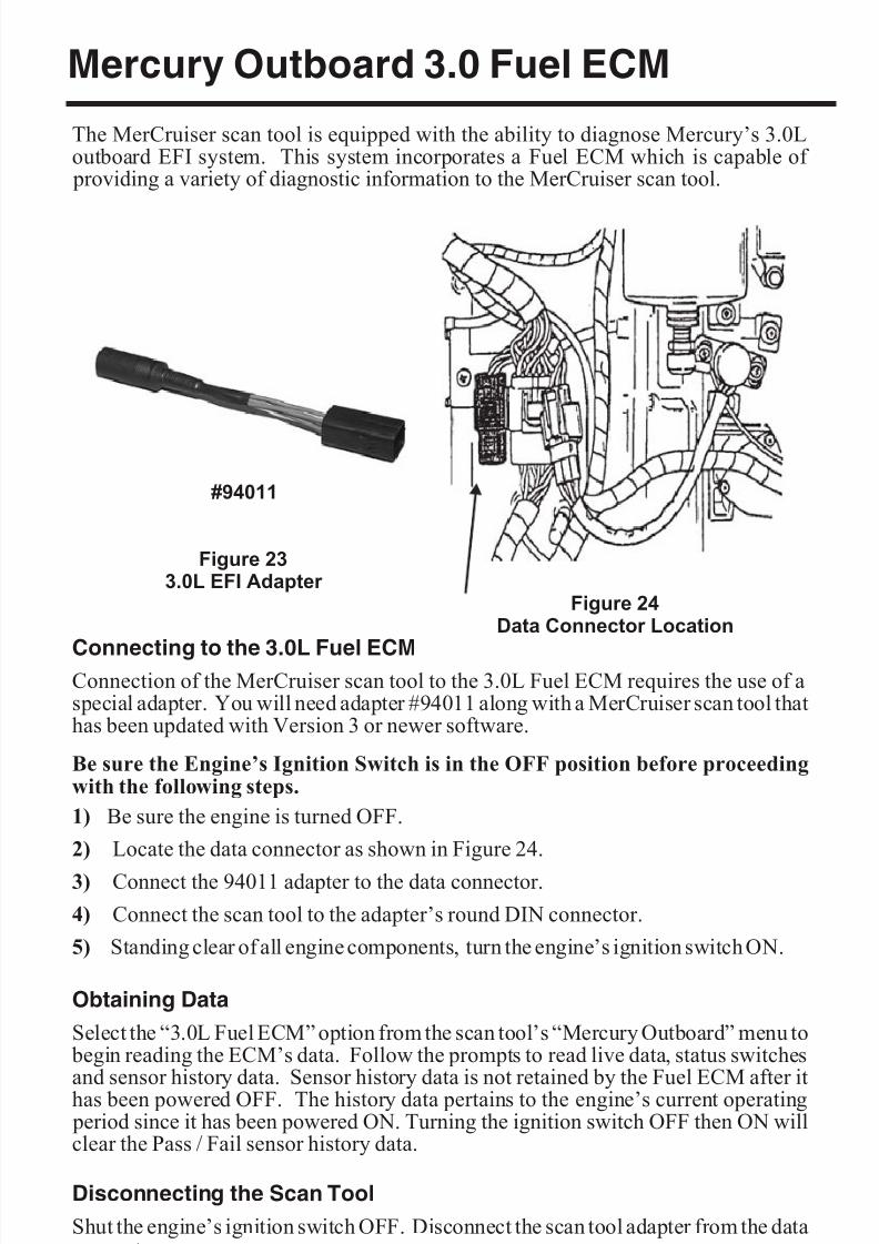
8/8/2019 Merc Manual v5
http://slidepdf.com/reader/full/merc-manual-v5 66/76
Mercury Outboard 3.0 Fuel ECM
The MerCruiser scan tool is equipped with the ability to diagnose Mercury’s 3.0Loutboard EFI system. This system incorporates a Fuel ECM which is capable of
providing a variety of diagnostic information to the MerCruiser scan tool.
Connecting to the 3.0L Fuel ECMConnection of the MerCruiser scan tool to the 3.0L Fuel ECM requires the use of aspecial adapter. You will need adapter #94011 along with a MerCruiser scan tool thathas been updated with Version 3 or newer software.
Be sure the Engine’s Ignition Switch is in the OFF position before proceedingwith the following steps.
1) Be sure the engine is turned OFF.
2) Locate the data connector as shown in Figure 24.
3) Connect the 94011 adapter to the data connector.
4) Connect the scan tool to the adapter’s round DIN connector.
5) Standing clear of all engine components, turn the engine’s ignition switch ON.
Obtaining Data
Select the “3.0L Fuel ECM” option from the scan tool’s “Mercury Outboard” menu to begin reading the ECM’s data. Follow the prompts to read live data, status switchesand sensor history data. Sensor history data is not retained by the Fuel ECM after ithas been powered OFF. The history data pertains to the engine’s current operating
period since it has been powered ON. Turning the ignition switch OFF then ON willclear the Pass / Fail sensor history data.
Disconnecting the Scan Tool
Shut the engine’s ignition switch OFF. Disconnect the scan tool adapter from the dataconnector.
Page 62
Figure 24Data Connector Location
Figure 233.0L EFI Adapter
#94011
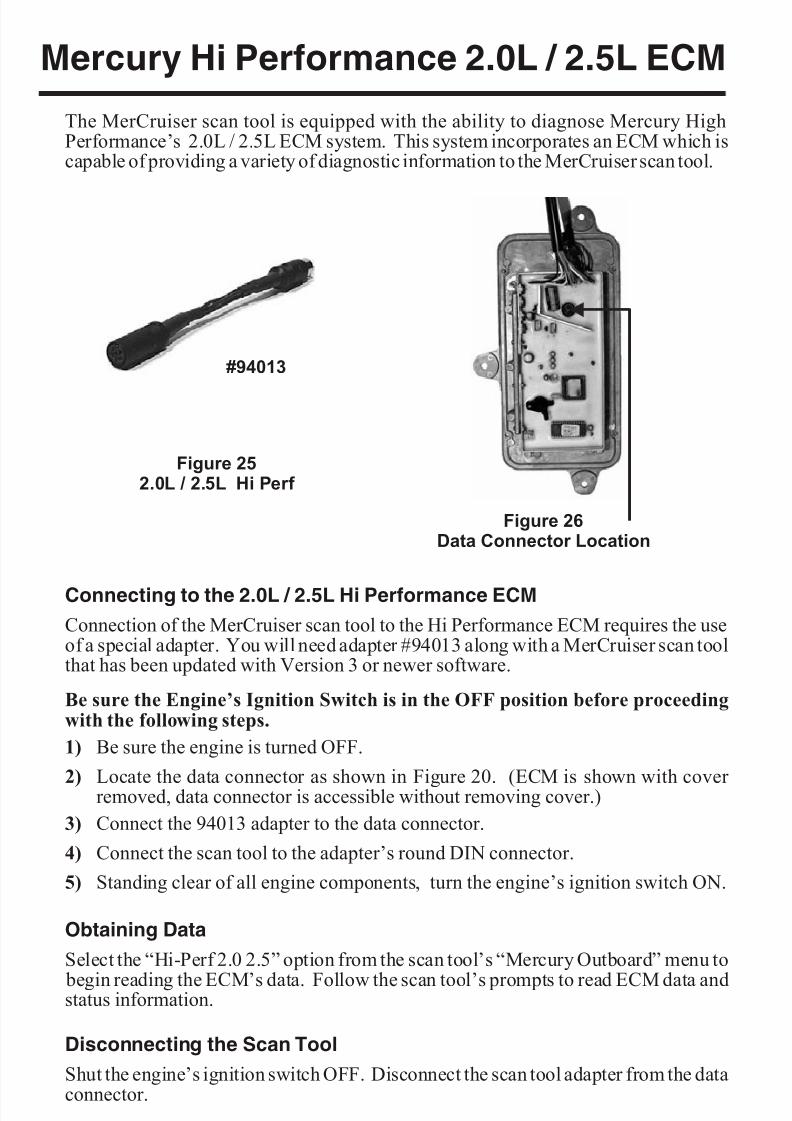
8/8/2019 Merc Manual v5
http://slidepdf.com/reader/full/merc-manual-v5 67/76
Mercury Hi Performance 2.0L / 2.5L ECM
The MerCruiser scan tool is equipped with the ability to diagnose Mercury HighPerformance’s 2.0L / 2.5L ECM system. This system incorporates an ECM which iscapable of providing a variety of diagnostic information to the MerCruiser scan tool.
Connecting to the 2.0L / 2.5L Hi Performance ECM
Connection of the MerCruiser scan tool to the Hi Performance ECM requires the useof a special adapter. You will need adapter #94013 along with a MerCruiser scan toolthat has been updated with Version 3 or newer software.
Be sure the Engine’s Ignition Switch is in the OFF position before proceedingwith the following steps.
1) Be sure the engine is turned OFF.
2) Locate the data connector as shown in Figure 20. (ECM is shown with cover removed, data connector is accessible without removing cover.)
3) Connect the 94013 adapter to the data connector.
4) Connect the scan tool to the adapter’s round DIN connector.
5) Standing clear of all engine components, turn the engine’s ignition switch ON.
Obtaining Data
Select the “Hi-Perf 2.0 2.5” option from the scan tool’s “Mercury Outboard” menu to
begin reading the ECM’s data. Follow the scan tool’s prompts to read ECM data andstatus information.
Disconnecting the Scan Tool
Shut the engine’s ignition switch OFF. Disconnect the scan tool adapter from the dataconnector.
Page 63
Figure 252.0L / 2.5L Hi Perf
Figure 26Data Connector Location
#94013
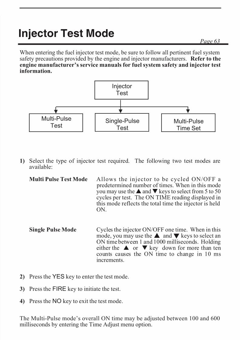
8/8/2019 Merc Manual v5
http://slidepdf.com/reader/full/merc-manual-v5 68/76
Injector Test Mode
When entering the fuel injector test mode, be sure to follow all pertinent fuel systemsafety precautions provided by the engine and injector manufacturers. Refer to theengine manufacturer’s service manuals for fuel system safety and injector testinformation.
1) Select the type of injector test required. The following two test modes areavailable:
Multi Pulse Test Mode Allows the injector to be cycled ON/OFF a predetermined number of times. When in this mode
you may use thes
andt
keys to select from 5 to 50cycles per test. The ON TIME reading displayed inthis mode reflects the total time the injector is heldON.
Single Pulse Mode Cycles the injector ON/OFF one time. When in thismode, you may use thes andt keys to select anON time between 1 and 1000 milliseconds. Holdingeither the s or t key down for more than ten
counts causes the ON time to change in 10 msincrements.
2) Press the YES key to enter the test mode.
3) Press the FIRE key to initiate the test.
4) Press the NO key to exit the test mode.
The Multi-Pulse mode’s overall ON time may be adjusted between 100 and 600milliseconds by entering the Time Adjust menu option.
Page 64
Multi-PulseTest
Injector Test
Single-PulseTest
Multi-PulseTime Set
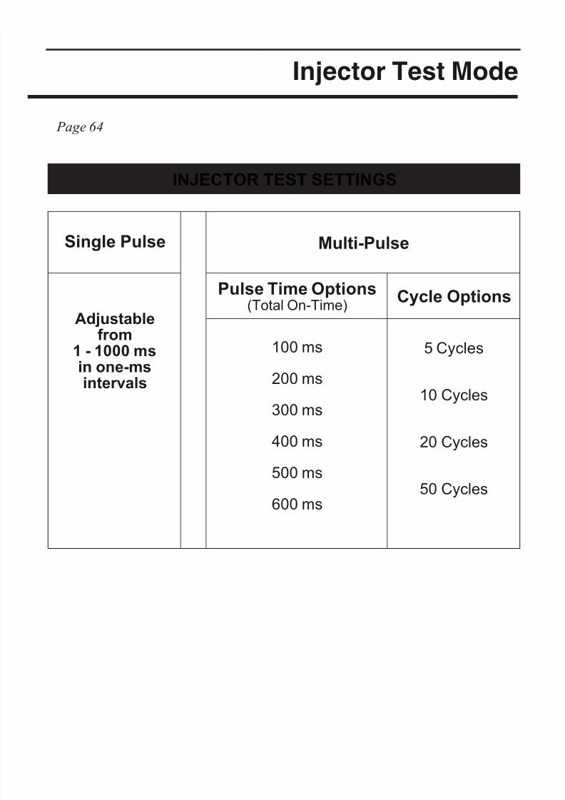
8/8/2019 Merc Manual v5
http://slidepdf.com/reader/full/merc-manual-v5 69/76
Injector Test Mode
INJECTOR TEST SETTINGS
Single Pulse Multi-Pulse
Adjustablefrom
1 - 1000 msin one-msintervals
Pulse Time Options
(Total On-Time)
Cycle Options
100 ms
200 ms
300 ms
400 ms
500 ms
600 ms
5 Cycles
10 Cycles
20 Cycles
50 Cycles
Page 65
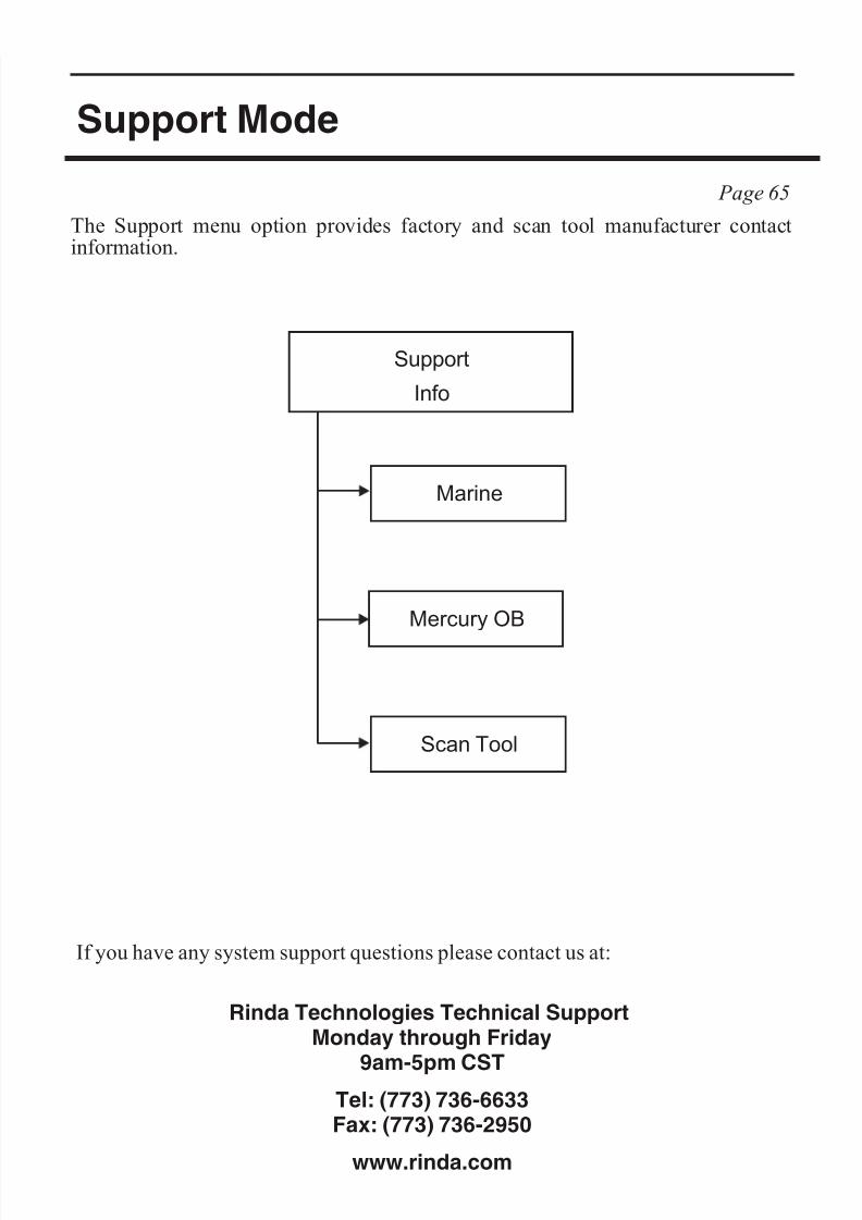
8/8/2019 Merc Manual v5
http://slidepdf.com/reader/full/merc-manual-v5 70/76
Support Mode
The Support menu option provides factory and scan tool manufacturer contactinformation.
If you have any system support questions please contact us at:
Rinda Technologies Technical SupportMonday through Friday
9am-5pm CST
Tel: (773) 736-6633
Fax: (773) 736-2950
www.rinda.com
Page 66
Scan Tool
Marine
Mercury OB
Support
Info
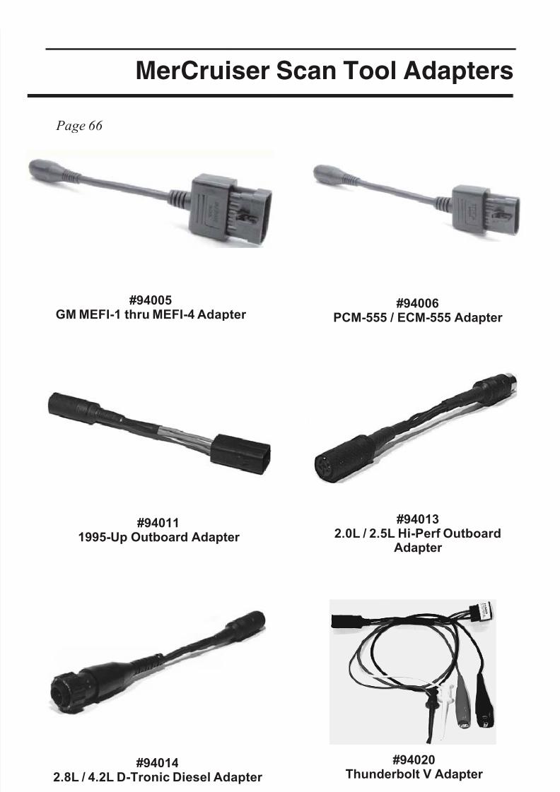
8/8/2019 Merc Manual v5
http://slidepdf.com/reader/full/merc-manual-v5 71/76
MerCruiser Scan Tool Adapters
Continued on the next page.
Page 67
#94005GM MEFI-1 thru MEFI-4 Adapter #94006PCM-555 / ECM-555 Adapter
#940142.8L / 4.2L D-Tronic Diesel Adapter
#940132.0L / 2.5L Hi-Perf Outboard
Adapter
#940111995-Up Outboard Adapter
#94020Thunderbolt V Adapter
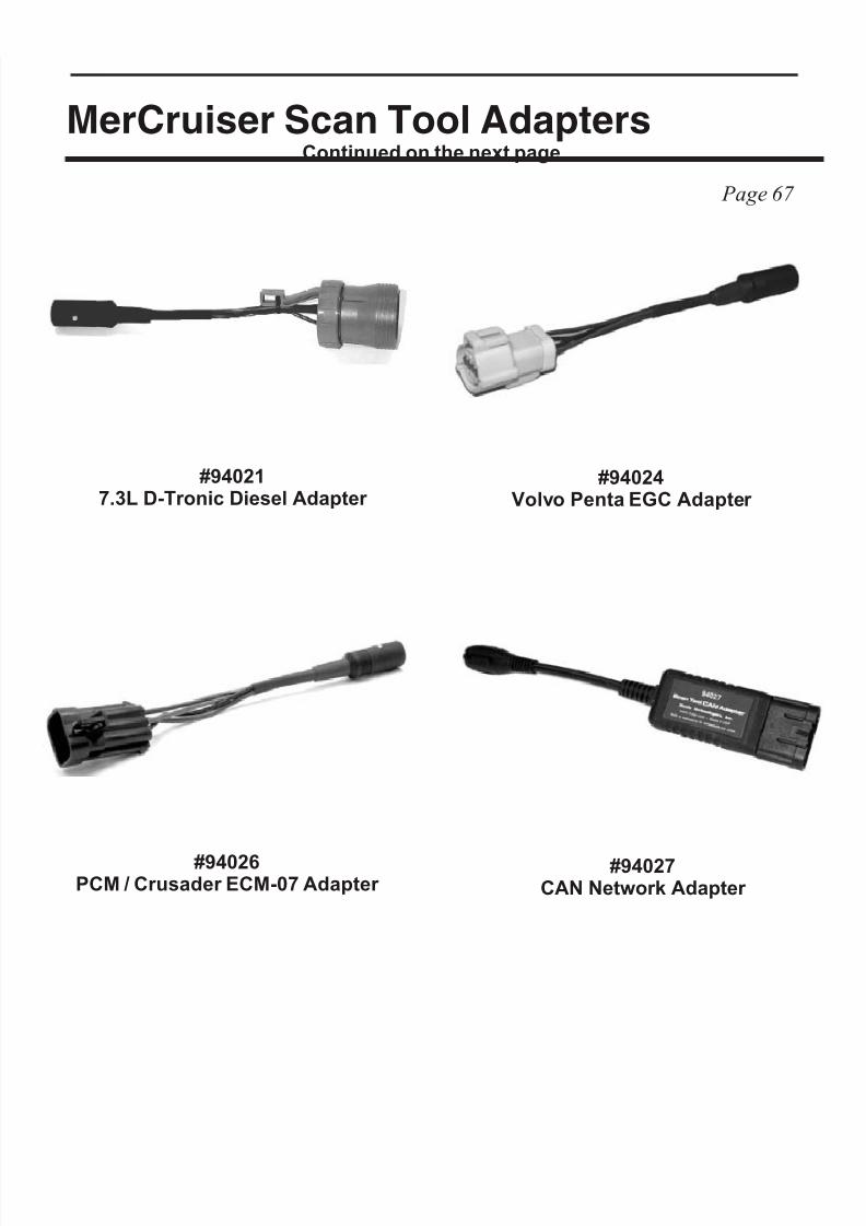
8/8/2019 Merc Manual v5
http://slidepdf.com/reader/full/merc-manual-v5 72/76
MerCruiser Scan Tool Adapters
Page 68
#940217.3L D-Tronic Diesel Adapter
#94026PCM / Crusader ECM-07 Adapter
#94024 Volvo Penta EGC Adapter
#94027CAN Network Adapter

8/8/2019 Merc Manual v5
http://slidepdf.com/reader/full/merc-manual-v5 73/76
Page 69
Notes:

8/8/2019 Merc Manual v5
http://slidepdf.com/reader/full/merc-manual-v5 74/76
Page 70
Notes:

8/8/2019 Merc Manual v5
http://slidepdf.com/reader/full/merc-manual-v5 75/76
Page 71
Notes:

8/8/2019 Merc Manual v5
http://slidepdf.com/reader/full/merc-manual-v5 76/76