Embed Size (px)
Citation preview
Meraki MR12/16Hardware Installation Guide
TrademarksMeraki, Meraki MR12, Meraki MR16, Meraki Cloud Controller, and Meraki Mesh are trademarks of Meraki, Inc. Other brand and product names are registered trademarks or trademarks of their respective holders. Statement of Conditions In the interest of improving internal design, operational function, and/or reliability, Meraki reserves the right to make changes to the products described in this document without notice. Meraki does not assume any liability that may occur due to the use or application of the product(s) or circult layout(s) described herein.
WarrantyMeraki, Inc. provides a lifetime warranty on this product. Warranty details may be found at www.meraki.com/legal.
3
Table of Contents 1 Scope of Document and Related Publications 4
2 MR16 Overview 5 2.1 Package Contents 5 2.2 Understanding the MR16 5 2.3 Security Features 7 2.4 Ethernet Ports 7 2.5 Power Source Options 7 2.6 Factory Reset Button 7 2.7 LED Indicators and Run Dark Mode 7 2.8 UL 2043 Plenum rating 8
3 Pre-Install Preparation 8 3.1 Confi gure Your Network in Dashboard 8 3.2 Check and Upgrade Firmware 8 3.3 Check and Confi gure Firewall Settings 8 3.4 Assigning IP Addresses to MR16s 9 3.4.1 Dynamic Assignment 9 3.4.2 Static Assignment 9 3.4.3 Static IP Assignment via DHCP Reservations 9 3.5 Collect Tools 10 3.6 Collect Additional Hardware for Installation 10
4 Installation Instructions 11 4.1 Choose Your Mounting Location 11 4.2 Install the MR16 11 4.2.1 Attach the Mount Plate 11 4.2.1.1 Wall or Solid Ceiling Mount Using Mount Plate 13 4.2.1.2 Drop Ceiling Mount Using Mount Plate 14 4.2.1.3 Electrical Junction Box Mount Using Mount Plate 18 4.2.1.4 Plenum Mount (Above Drop Ceiling) 19 4.2.2 Power the MR16 20 4.2.2.1 Powering the MR16 with Meraki AC Adapter 21 4.2.2.2 Powering the MR16 with Meraki 802.3af Power over Ethernet Injector 21 4.2.2.3 Powering the MR16 with an 802.3af Power over Ethernet Switch 22 4.2.3 Mount the MR16 22 4.2.3.1 Assemble MR16 to the Mount Plate 22 4.2.3.2 Desk or Shelf Mount 24 4.2.3.3 Wall or Solid Ceiling Mount without Mount Plate 24 4.3 Secure the MR16 25 4.3.1 Security Screw 25 4.3.2 Kensington Lock 25 4.4 Verify Device Functionality and Test Network Coverage 26
5 Troubleshooting 26
6 Regulatory Information for MR12 27
7 Regulatory Information for MR16 31
4
1 Scope of Document and Related Publications
The MR12/16 Hardware Installation Guide describes the installation procedure for the MR12 and MR16 access points. Note: All instructions in this hardware installation guide reference the MR16 product but apply equally to the MR12.
Additional reference documents are available online at www.meraki.com/library/product.
5
MR16 access point Drop ceiling mounting kit
2 MR12 and MR16 Overview The Meraki MR12 is an enterprise-class 802.11n access point designed for deployment in small and medium businesses, home and branch offi ces, schools, hotels and retail stores. The Meraki MR16 is an enterprise-class, dual-concurrent 802.11n access point designed for high-density deployments in large offi ces, schools, hospitals, hotels and large retail stores. When connected to the Meraki Cloud Controller, MR12 and MR16 enable the creation of high-speed, reliable indoor wireless networks quickly, easily and cost-effectively.
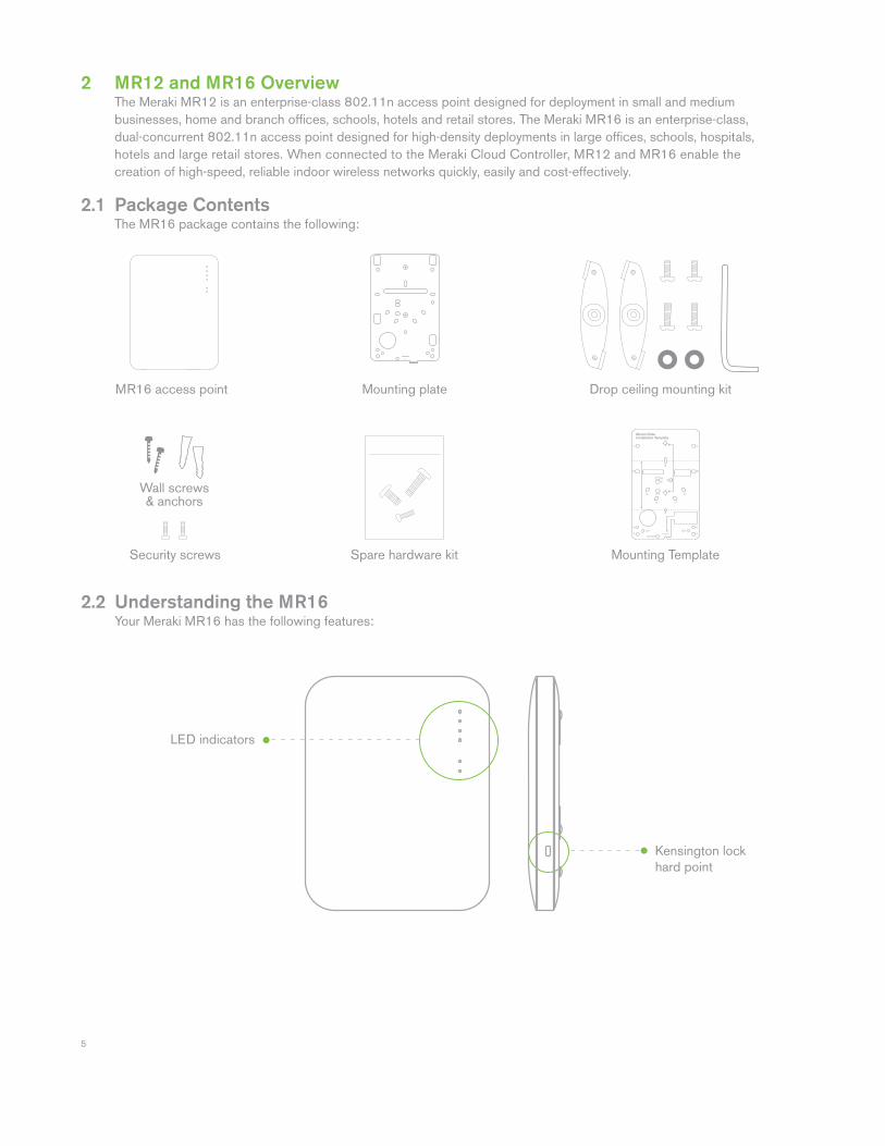
2.1 Package Contents The MR16 package contains the following:
2.2 Understanding the MR16 Your Meraki MR16 has the following features:
Kensington lock hard point
Spare hardware kitSecurity screws
Wall screws & anchors
LED indicators
Mounting Template
Mounting plate
6
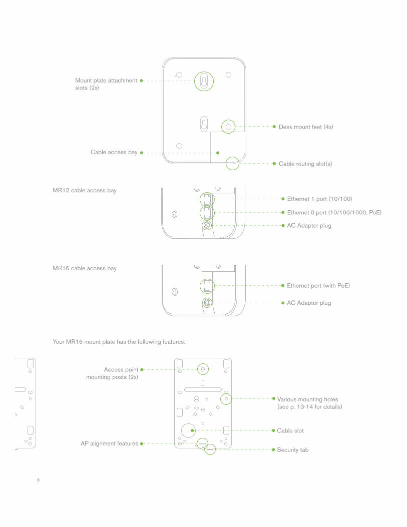
Cable slot
Security tab
Your MR16 mount plate has the following features:
MR16 cable access bay
MR12 cable access bay
Mount plate attachment slots (2x)
Access point mounting posts (2x)
Desk mount feet (4x)
Cable routing slot(s)
Cable access bay
AC Adapter plug
Ethernet 0 port (10/100/1000, PoE)
Ethernet 1 port (10/100)
AC Adapter plug
Ethernet port (with PoE)
Various mounting holes (see p. 13-14 for details)
AP alignment features
7
2.3 Security Features The MR16 features multiple options for physically securing the access point after installation: 1. Security screw – The accessory kit includes screws that can be used to secure the access point to the mount plate. Engaging the security screw prevents accidental dislodging and theft. 2. Kensington lock – The access point contains a hard point that allows it to be secured to any nearby permanent structure using a standard Kensington lock.
2.4 Ethernet Ports Both MR12 and MR16 feature a Gigabit Ethernet RJ45 port that accepts 802.3af power (labeled “Eth0, PoE”). This port should be used for uplink to your WAN connection. MR12 also features an additional Fast Ethernet RJ45 port (labeled Eth1) that can be used to connect additional LAN devices such as printers and IP phones.
2.5 Power Source Options The MR16 access point can be powered using either the Meraki AC Adapter or 802.3af PoE Injector (both sold separately) or a third-party 802.3af PoE switch.
2.6 Factory Reset Button If the button is pressed and held for at least fi ve seconds and then released, the MR16 will reboot and be restored to its original factory settings by deleting all confi guration information stored on the unit.
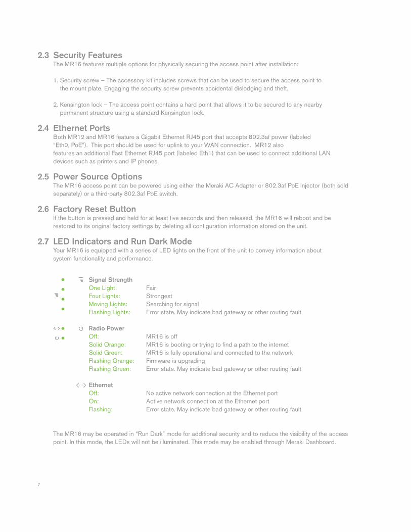
2.7 LED Indicators and Run Dark Mode Your MR16 is equipped with a series of LED lights on the front of the unit to convey information about system functionality and performance.
The MR16 may be operated in “Run Dark” mode for additional security and to reduce the visibility of the access point. In this mode, the LEDs will not be illuminated. This mode may be enabled through Meraki Dashboard.
Signal Strength
One Light: Fair Four Lights: Strongest Moving Lights: Searching for signal Flashing Lights: Error state. May indicate bad gateway or other routing fault
Radio Power
Off: MR16 is off Solid Orange: MR16 is booting or trying to fi nd a path to the internet Solid Green: MR16 is fully operational and connected to the network Flashing Orange: Firmware is upgrading Flashing Green: Error state. May indicate bad gateway or other routing fault Ethernet Off: No active network connection at the Ethernet port On: Active network connection at the Ethernet port Flashing: Error state. May indicate bad gateway or other routing fault
8
2.7 UL 2043 Plenum rating* The MR16 meets the UL 2043 plenum-rating standard. This certifi es that the MR16 has adequate fi re resistance and low smoke-emission characteristics to be mounted and operated in a building’s environmental air spaces, such as above suspended ceilings in an offi ce environment. (*UL 2043 rating applies to MR16 only.)
3 Pre-Install Preparation You should complete the following steps before going on-site to perform an installation.
3.1 Confi gure Your Network in Dashboard The following is a brief overview only of the steps required to add an MR16 to your network. For detailed instructions about creating, confi guring and managing Meraki wireless networks, refer to the Meraki Cloud Controller Manual (meraki.com/library/product). 1. Login to http://dashboard.meraki.com. If this is your fi rst time, create a new account. 2. Find the network to which you plan to add your APs or create a new network. 3. Add your APs to your network. You will need your Meraki order number (found on your invoice if you ordered directly from Meraki) or the serial number of each AP, which looks like Qxxx-xxxx-xxxx, and is found on the bottom of the unit. You will also need your Enterprise Cloud Controller license key, which you should have received via email from [email protected]. 4. Go to the map / fl oor plan view and place each AP on the map by clicking and dragging it to the location where you plan to mount it.
3.2 Check and Upgrade Firmware To ensure your MR16 performs optimally immediately following installation, Meraki recommends that you facilitate a fi rmware upgrade prior to mounting your MR16. 1. Attach your MR16 to power and a wired Internet connection. See p. 19 of this Hardware Installation Guide for details. 2. The MR16 will turn on and the Power LED will glow solid orange. If the unit does not require a fi rmware upgrade, the Power LED will turn green within thirty seconds. * If the unit requires an upgrade, the Power LED will begin blinking orange until the upgrade is complete, at which point the Power LED will turn solid green. You should allow about an hour for the fi rmware upgrade to complete, depending on the speed of your internet connection. 3.3 Check and Confi gure Firewall Settings If a fi rewall is in place, it must allow outgoing connections on particular ports to particular IP addresses. The most current list of outbound ports and IP addresses can be found here: http://tinyurl.com/y79une3
9
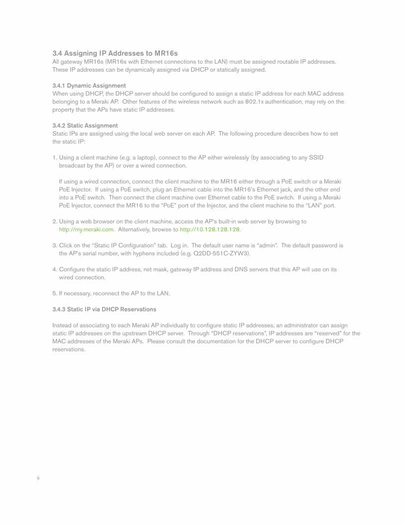
3.4 Assigning IP Addresses to MR16s All gateway MR16s (MR16s with Ethernet connections to the LAN) must be assigned routable IP addresses. These IP addresses can be dynamically assigned via DHCP or statically assigned.
3.4.1 Dynamic Assignment
When using DHCP, the DHCP server should be confi gured to assign a static IP address for each MAC address belonging to a Meraki AP. Other features of the wireless network such as 802.1x authentication, may rely on the property that the APs have static IP addresses. 3.4.2 Static Assignment
Static IPs are assigned using the local web server on each AP. The following procedure describes how to set the static IP: 1. Using a client machine (e.g. a laptop), connect to the AP either wirelessly (by associating to any SSID broadcast by the AP) or over a wired connection. If using a wired connection, connect the client machine to the MR16 either through a PoE switch or a Meraki PoE Injector. If using a PoE switch, plug an Ethernet cable into the MR16’s Ethernet jack, and the other end into a PoE switch. Then connect the client machine over Ethernet cable to the PoE switch. If using a Meraki PoE Injector, connect the MR16 to the “PoE” port of the Injector, and the client machine to the “LAN” port. 2. Using a web browser on the client machine, access the AP’s built-in web server by browsing to http://my.meraki.com. Alternatively, browse to http://10.128.128.128.
3. Click on the “Static IP Confi guration” tab. Log in. The default user name is “admin”. The default password is the AP’s serial number, with hyphens included (e.g. Q2DD-551C-ZYW3).
4. Confi gure the static IP address, net mask, gateway IP address and DNS servers that this AP will use on its wired connection.
5. If necessary, reconnect the AP to the LAN.
3.4.3 Static IP via DHCP Reservations
Instead of associating to each Meraki AP individually to confi gure static IP addresses, an administrator can assign static IP addresses on the upstream DHCP server. Through “DHCP reservations”, IP addresses are “reserved” for the MAC addresses of the Meraki APs. Please consult the documentation for the DHCP server to confi gure DHCP reservations.
10
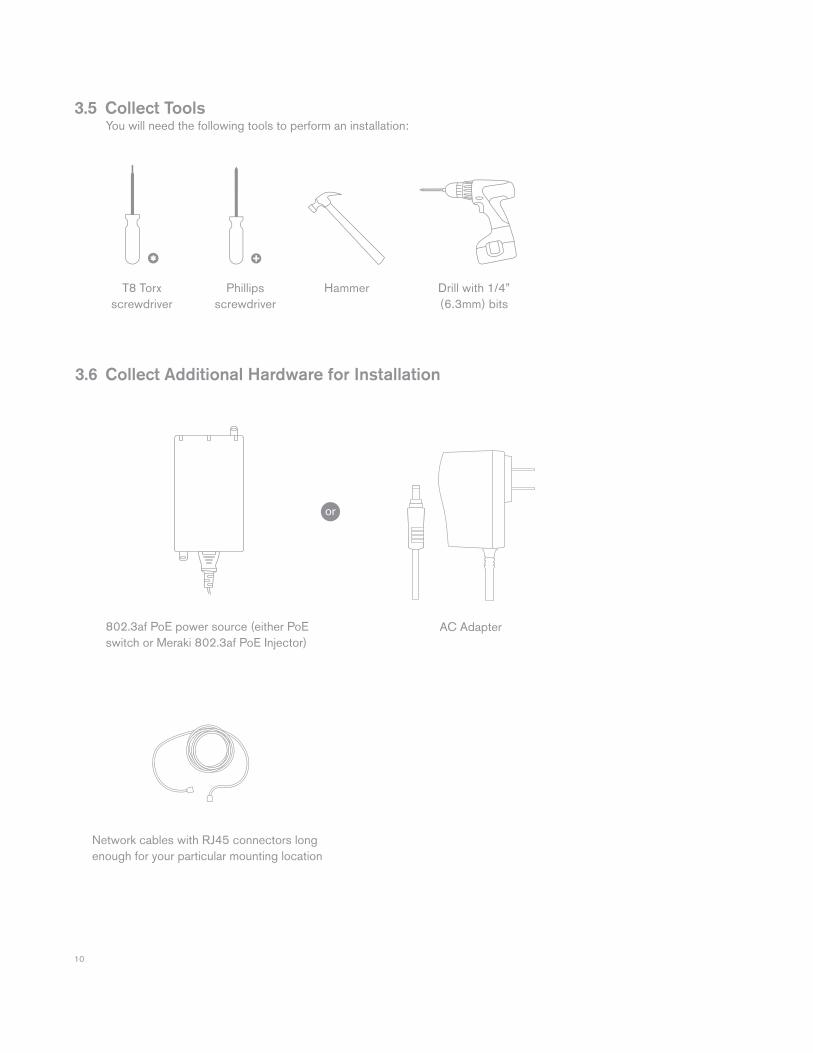
T8 Torxscrewdriver
Phillips screwdriver
Hammer Drill with 1/4” (6.3mm) bits
3.6 Collect Additional Hardware for Installation
802.3af PoE power source (either PoE switch or Meraki 802.3af PoE Injector)
Network cables with RJ45 connectors long enough for your particular mounting location
3.5 Collect Tools You will need the following tools to perform an installation:
AC Adapter
or
11
4 Installation Instructions
4.1 Choose Your Mounting Location A good mounting location is important to getting the best performance out of your MR16 access point. Keep the following in mind: 1. The device should have unobstructed line of sight to most coverage areas. For example, if installing in an offi ce fi lled with workspaces divided by mid-height cubicle walls, installing on the ceiling or high on a wall would be ideal. 2. Power over Ethernet supports a maximum cable length of 300 ft (100 m). 3. If being used in a mesh deployment, the MR16 should have line of sight to at least two other Meraki devices. For more detailed instructions regarding access point location selection, reference the Meraki Network Design Guide (meraki.com/library/product).
4.2 Install the MR16 For most mounting scenarios, the MR16 mount plate provides a quick, simple, and fl exible means of mounting your device. The installation should be done in two steps. First, install the mount plate to your selected location. Then, attach the MR16 to the mount plate.
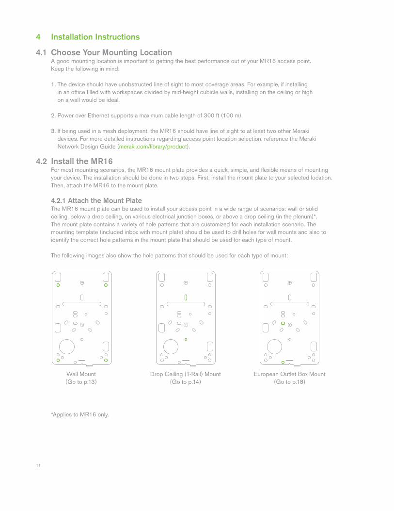
4.2.1 Attach the Mount Plate The MR16 mount plate can be used to install your access point in a wide range of scenarios: wall or solid ceiling, below a drop ceiling, on various electrical junction boxes, or above a drop ceiling (in the plenum)*. The mount plate contains a variety of hole patterns that are customized for each installation scenario. The mounting template (included inbox with mount plate) should be used to drill holes for wall mounts and also to identify the correct hole patterns in the mount plate that should be used for each type of mount.
The following images also show the hole patterns that should be used for each type of mount:
Wall Mount(Go to p.13)
Drop Ceiling (T-Rail) Mount(Go to p.14)
European Outlet Box Mount(Go to p.18)
*Applies to MR16 only.
12
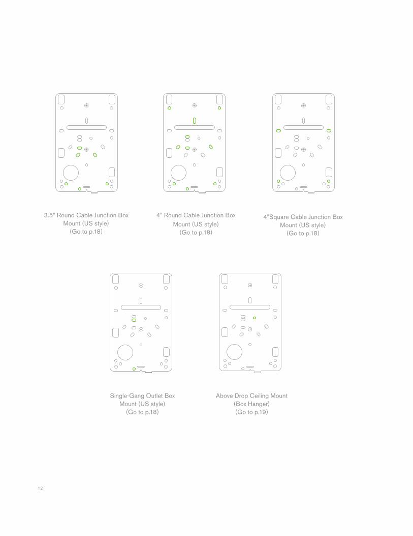
3.5” Round Cable Junction Box Mount (US style)
(Go to p.18)
Single-Gang Outlet Box Mount (US style)
(Go to p.18)
Above Drop Ceiling Mount(Box Hanger)(Go to p.19)
4” Round Cable Junction Box Mount (US style)
(Go to p.18)
4”Square Cable Junction Box Mount (US style)
(Go to p.18)
13
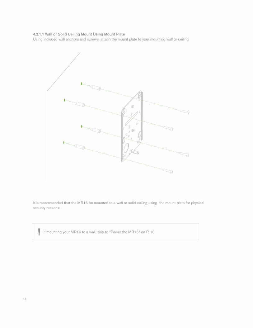
4.2.1.1 Wall or Solid Ceiling Mount Using Mount Plate
Using included wall anchors and screws, attach the mount plate to your mounting wall or ceiling.
It is recommended that the MR16 be mounted to a wall or solid ceiling using the mount plate for physical security reasons.
If mounting your MR16 to a wall, skip to “Power the MR16“ on P. 18
14
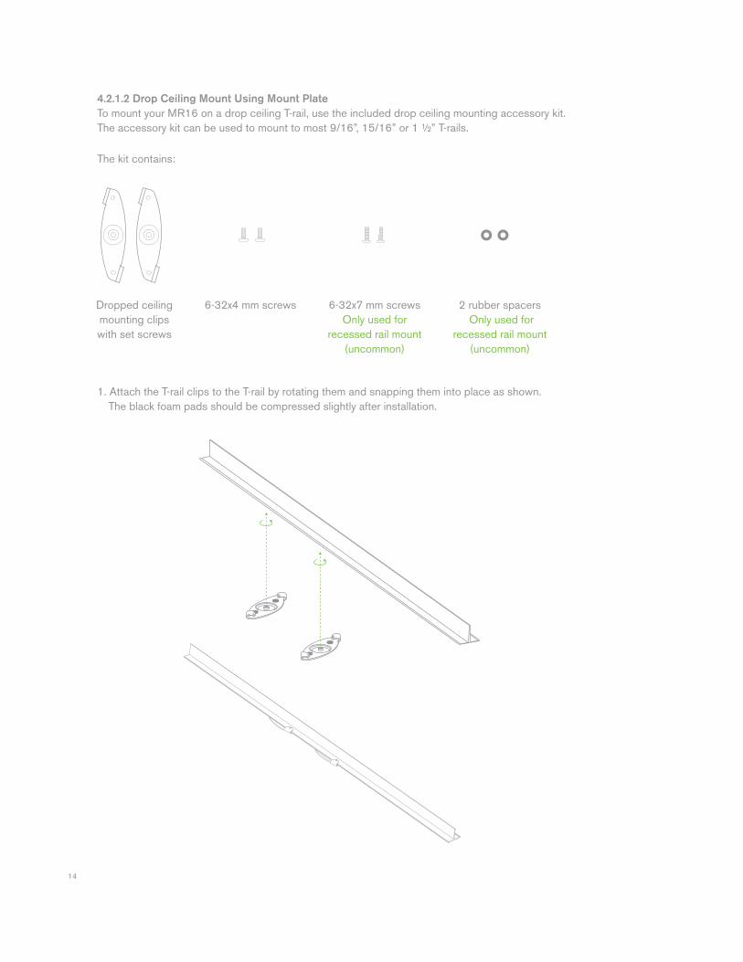
1. Attach the T-rail clips to the T-rail by rotating them and snapping them into place as shown. The black foam pads should be compressed slightly after installation.
4.2.1.2 Drop Ceiling Mount Using Mount Plate
To mount your MR16 on a drop ceiling T-rail, use the included drop ceiling mounting accessory kit. The accessory kit can be used to mount to most 9/16”, 15/16” or 1 ½” T-rails.
Dropped ceiling mounting clipswith set screws
6-32x4 mm screws 6-32x7 mm screwsOnly used for
recessed rail mount (uncommon)
2 rubber spacers Only used for
recessed rail mount (uncommon)
The kit contains:
15
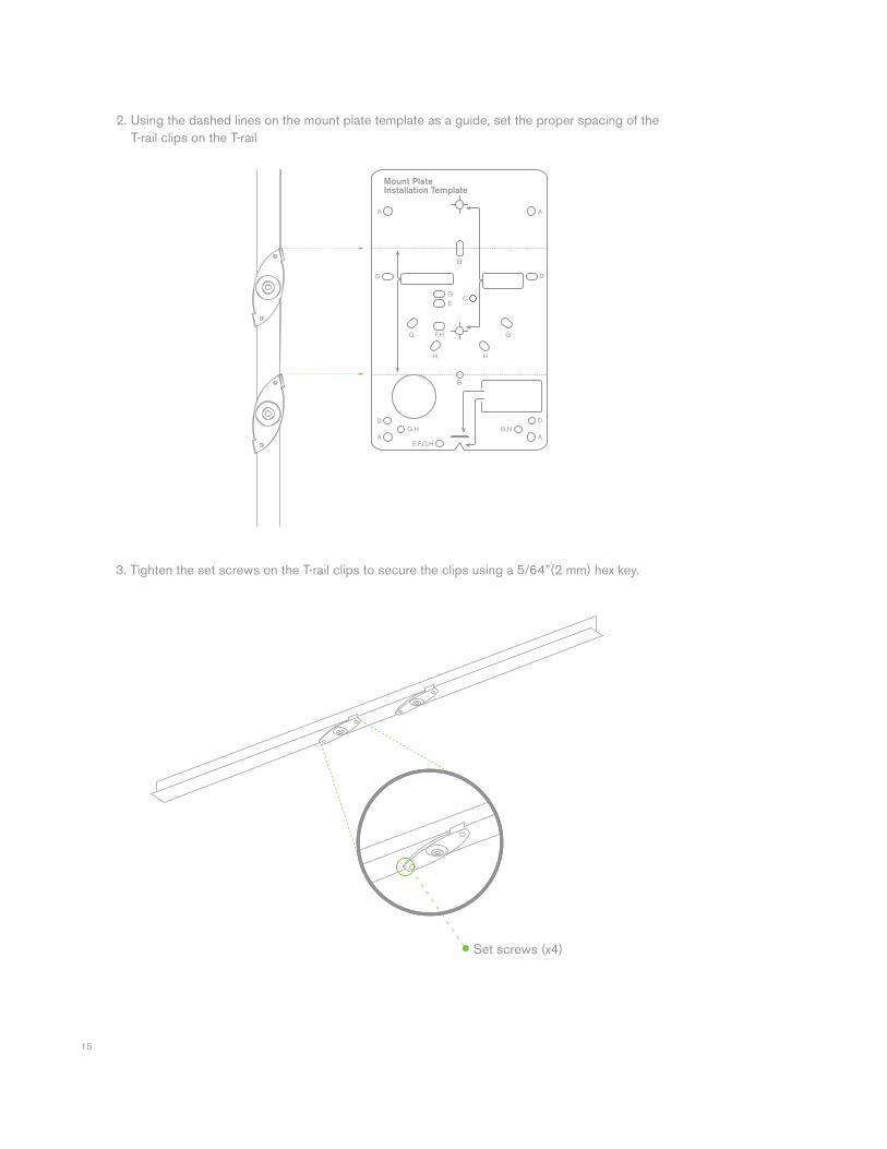
3. Tighten the set screws on the T-rail clips to secure the clips using a 5/64”(2 mm) hex key.
2. Using the dashed lines on the mount plate template as a guide, set the proper spacing of the T-rail clips on the T-rail
Set screws (x4)
16
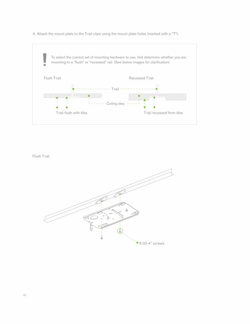
4. Attach the mount plate to the T-rail clips using the mount plate holes (marked with a “T“).
To select the correct set of mounting hardware to use, first determine whether you are mounting to a “flush” or “recessed“ rail. (See below images for clarification)
Flush T-rail Recessed T-rail
T-rail fl ush with tiles T-rail recessed from tiles
Ceiling tiles
T-rail
6-32-4” screws
Flush T-rail
17
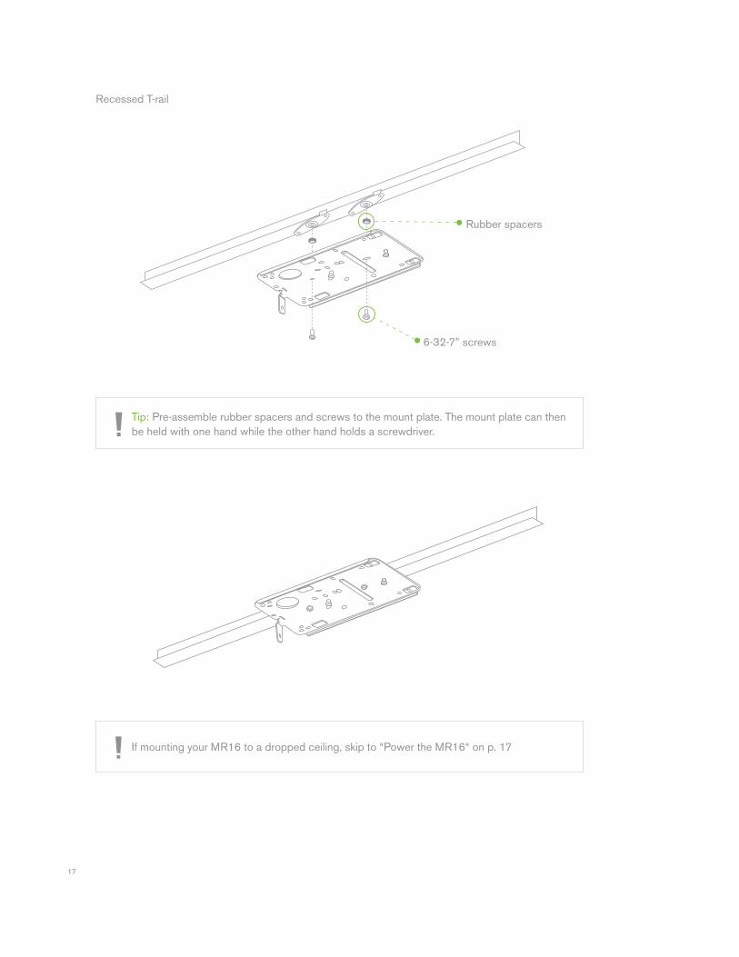
Rubber spacers
6-32-7” screws
Tip: Pre-assemble rubber spacers and screws to the mount plate. The mount plate can then be held with one hand while the other hand holds a screwdriver.
If mounting your MR16 to a dropped ceiling, skip to “Power the MR16“ on p. 17
Recessed T-rail
18
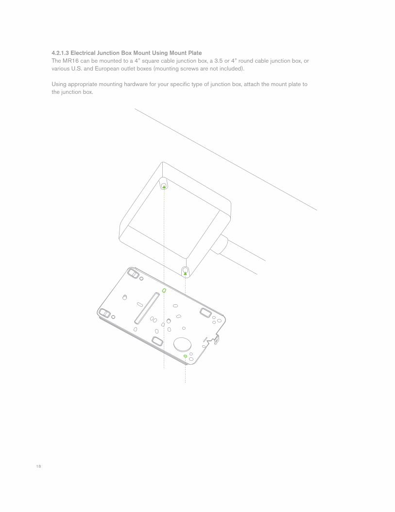
4.2.1.3 Electrical Junction Box Mount Using Mount Plate
The MR16 can be mounted to a 4” square cable junction box, a 3.5 or 4” round cable junction box, or various U.S. and European outlet boxes (mounting screws are not included).
Using appropriate mounting hardware for your specific type of junction box, attach the mount plate to the junction box.
19
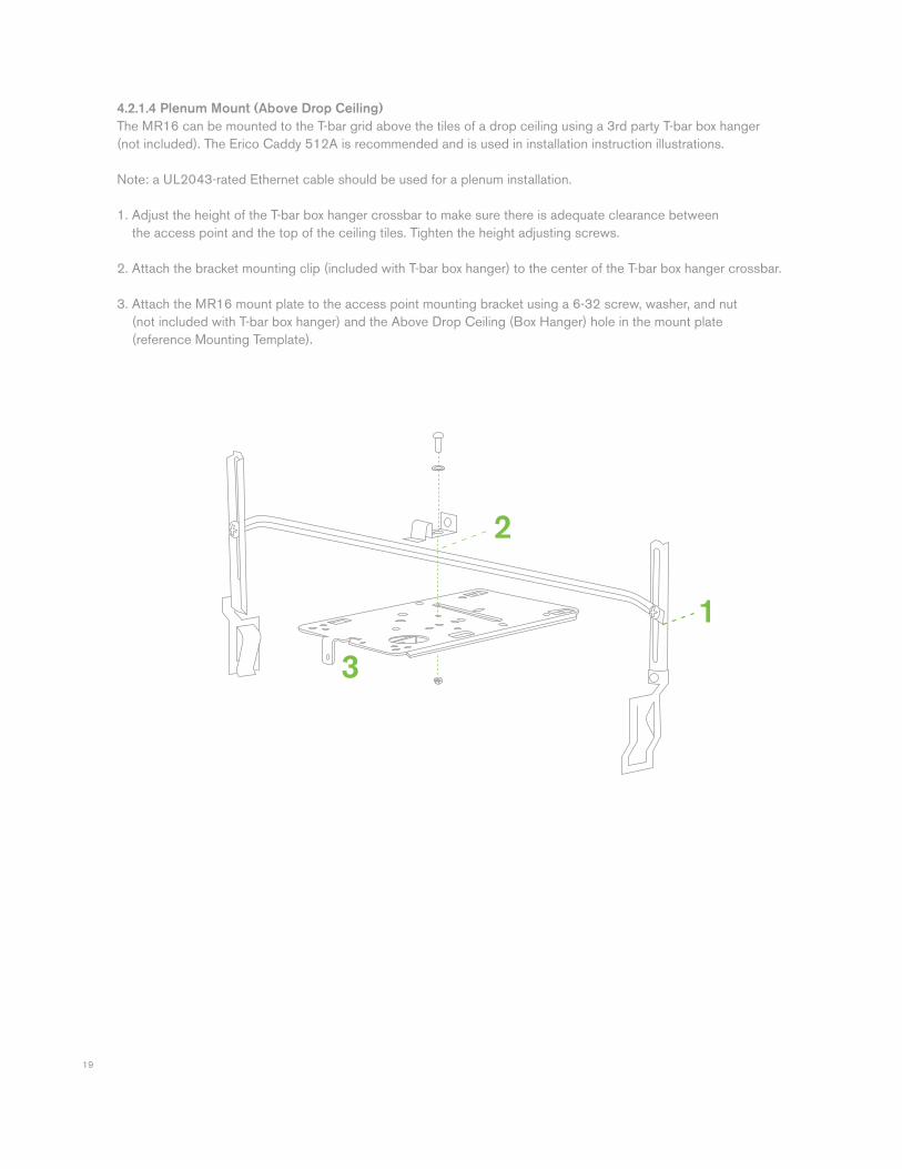
4.2.1.4 Plenum Mount (Above Drop Ceiling)
The MR16 can be mounted to the T-bar grid above the tiles of a drop ceiling using a 3rd party T-bar box hanger (not included). The Erico Caddy 512A is recommended and is used in installation instruction illustrations.
Note: a UL2043-rated Ethernet cable should be used for a plenum installation.
1. Adjust the height of the T-bar box hanger crossbar to make sure there is adequate clearance between the access point and the top of the ceiling tiles. Tighten the height adjusting screws.
2. Attach the bracket mounting clip (included with T-bar box hanger) to the center of the T-bar box hanger crossbar.
3. Attach the MR16 mount plate to the access point mounting bracket using a 6-32 screw, washer, and nut (not included with T-bar box hanger) and the Above Drop Ceiling (Box Hanger) hole in the mount plate (reference Mounting Template).
2
1
3
20
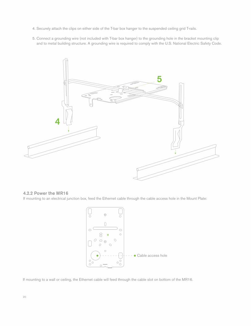
4.2.2 Power the MR16If mounting to an electrical junction box, feed the Ethernet cable through the cable access hole in the Mount Plate:
If mounting to a wall or ceiling, the Ethernet cable will feed through the cable slot on bottom of the MR16.
Cable access hole
4. Securely attach the clips on either side of the T-bar box hanger to the suspended ceiling grid T-rails.
5. Connect a grounding wire (not included with T-bar box hanger) to the grounding hole in the bracket mounting clip and to metal building structure. A grounding wire is required to comply with the U.S. National Electric Safety Code.
5
4
21
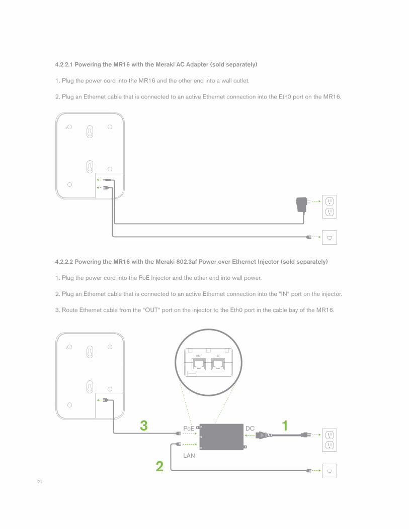
4.2.2.1 Powering the MR16 with the Meraki AC Adapter (sold separately)
1. Plug the power cord into the MR16 and the other end into a wall outlet. 2. Plug an Ethernet cable that is connected to an active Ethernet connection into the Eth0 port on the MR16.
4.2.2.2 Powering the MR16 with the Meraki 802.3af Power over Ethernet Injector (sold separately)
1. Plug the power cord into the PoE Injector and the other end into wall power. 2. Plug an Ethernet cable that is connected to an active Ethernet connection into the “IN“ port on the injector. 3. Route Ethernet cable from the “OUT“ port on the injector to the Eth0 port in the cable bay of the MR16.
1
2
3 DCPoE
LAN
22
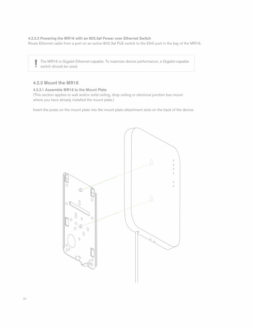
4.2.3 Mount the MR16
4.2.3.1 Assemble MR16 to the Mount Plate
(This section applies to wall and/or solid ceiling, drop ceiling or electrical junction box mount where you have already installed the mount plate.)
Insert the posts on the mount plate into the mount plate attachment slots on the back of the device.
4.2.2.3 Powering the MR16 with an 802.3af Power over Ethernet Switch
Route Ethernet cable from a port on an active 802.3af PoE switch to the Eth0 port in the bay of the MR16.
The MR16 is Gigabit Ethernet-capable. To maximize device performance, a Gigabit-capable switch should be used.
23
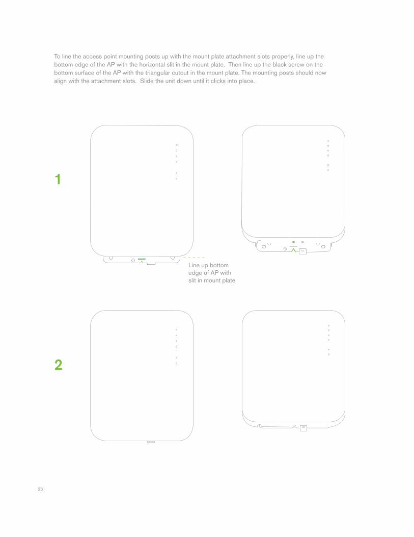
To line the access point mounting posts up with the mount plate attachment slots properly, line up the bottom edge of the AP with the horizontal slit in the mount plate. Then line up the black screw on the bottom surface of the AP with the triangular cutout in the mount plate. The mounting posts should now align with the attachment slots. Slide the unit down until it clicks into place.
2
1
Line up bottom edge of AP with slit in mount plate
24
4.2.3.2 Desk or Shelf Mount
The MR16 can be placed on a desk or shelf resting on the non-scratch rubber feet. The mount plate is not necessary for a desk or shelf mounting.
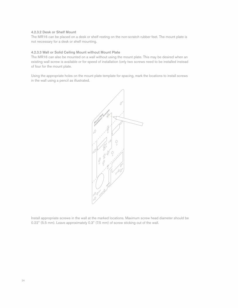
4.2.3.3 Wall or Solid Ceiling Mount without Mount Plate
The MR16 can also be mounted on a wall without using the mount plate. This may be desired when an existing wall screw is available or for speed of installation (only two screws need to be installed instead of four for the mount plate.
Using the appropriate holes on the mount plate template for spacing, mark the locations to install screws in the wall using a pencil as illustrated.
Install appropriate screws in the wall at the marked locations. Maximum screw head diameter should be 0.22” (5.5 mm). Leave approximately 0.3” (7.5 mm) of screw sticking out of the wall.
25
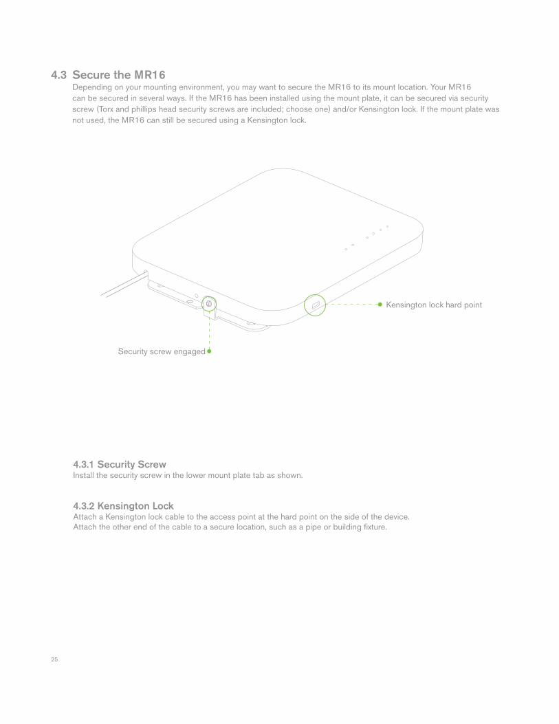
4.3 Secure the MR16 Depending on your mounting environment, you may want to secure the MR16 to its mount location. Your MR16 can be secured in several ways. If the MR16 has been installed using the mount plate, it can be secured via security screw (Torx and phillips head security screws are included; choose one) and/or Kensington lock. If the mount plate was not used, the MR16 can still be secured using a Kensington lock.
4.3.1 Security Screw Install the security screw in the lower mount plate tab as shown.
4.3.2 Kensington LockAttach a Kensington lock cable to the access point at the hard point on the side of the device.Attach the other end of the cable to a secure location, such as a pipe or building fi xture.
Security screw engaged
Kensington lock hard point
26
4.4 Verify Device Functionality and Test Network Coverage 1. Check LEDs The Radio Power LED should be solid green. If it is fl ashing orange, the fi rmware is automatically upgrading and the LED should turn green when the upgrade is completed (normally in under thirty minutes). If the device is a gateway, the Ethernet LED and the four Signal Strength LEDs should be green as well. If the device is a repeater only, the Ethernet LED will not be illuminated and the number of green Signal Strength LEDs will show the signal strength to the nearest Meraki device. See section 2.6 for further details about information conveyed by the LEDs. Note: Your MR16 must have an active route to the Internet to check and upgrade its fi rmware.
2. Verify access point connectivity Use any 802.11 client device to connect to the MR16 and verify proper connectivity using the client’s web browser.
3. Check network coverage Confi rm that you have good signal strength throughout your coverage area. You can use the signal strength meter on a laptop, smart phone, or other wireless device.
5 Troubleshooting Reference the Meraki knowledge base at http://meraki.com/support/knowledge_base for additional information and troubleshooting tips.
27
6 Regulatory Information for MR12 U.S. Regulatory Wireless Notice Federal Communication Commission Interference Statement: This equipment has been tested and found to comply with the limits for a Class B digital device, pursuant to Part 15 of the FCC Rules. These limits are designed to provide reasonable protection against harmful interference in a residential installation. This equipment generates, uses and can radiate radio frequency energy and, if not installed and used in accordance with the instructions, may cause harmful interference to radio communications. However, there is no guarantee that interference will not occur in a particular installation. If this equipment does cause harmful interference to radio or television reception, which can be determined by turning the equipment off and on, the user is encouraged to try to correct the interference by one of the following measures: • Reorient or relocate the receiving antenna. • Increase the separation between the equipment and receiver. • Connect the equipment into an outlet on a circuit different from that to which the receiver is connected. • Consult the dealer or an experienced radio/TV technician for help. FCC Caution:
Any changes or modifi cations not expressly approved by the party responsible for compliance could void the user’s authority to operate this equipment. This device complies with Part 15 of the FCC Rules. Operation is subject to the following two conditions: • this device may not cause harmful interference, and • this device must accept any interference received, including interference that may cause undesired operation.
FCC Radiation Exposure Statement: This equipment complies with FCC radiation exposure limits set forth for an uncontrolled environment. This equipment should be installed and operated with minimum distance 20 cm between the radiator and your body. This transmitter must not be co-located or operating in conjunction with any other antenna or transmitter. IEEE 802.11b or 802.11g operation of this product in the USA is fi rmware-limited to channels 1 through 11.
28
Canadian Regulatory Wireless Notice This device complies with RSS-210 of the Industry Canada Rules. Operation is subject to the following two conditions: • this device may not cause interference and • this device must accept any interference, including interference that may cause undesired operation of the device.
IC Radiation Exposure Statement: This equipment complies with IC radiation exposure limits set forth for an uncontrolled environment. This equipment should be installed and operated with minimum distance 20 cm between the radiator and your body.
Europe – EU Declaration of Conformity This device complies with the essential requirements of the R&TTE Directive 1999/5/EC. The following test methods have been applied in order to prove presumption of conformity with the essential requirements of the R&TTE Directive 1999/5/EC:
Radio: EN 300 328, EN 301 EMC: EN 301 489-1, EN 301 489-17 Safety: EN 60950-1 RF Exposure: EN 50385 Emissions: EN 55022 Immunity: EN 61000-4-2, EN 61000-4-3, EN 61000-4-4, EN 61000-4-5, EN 61000-4-6 This device is a 2.4 GHz wideband transmission system (transceiver), intended for use in all EU member states and EFTA countries with the following restrictions:
In Italy the end-user should apply for a license at the national spectrum authorities in order to obtain authorization to use the device for setting up outdoor radio links and/or for supplying public access to telecommunications and/or network services.
29
Česky (Czech) Meraki, Inc. tímto prohlašuje, že tento wireless device je ve shodě se základními požadavky a dalšími příslušnými ustanoveními směrnice.
Dansk (Danish) Undertegnede Meraki, Inc. erklærer herved, at følgende udstyr wireless device overholder de væsentlige krav og øvrige relevante krav i direktiv 1999/5/EF. Deutsch (German) Hiermit erklärt Meraki, Inc., dass sich das Gerät wireless device in Übereinstimmung mit den grundlegenden Anforderungen und den übrigen einschlägigen Bestimmungen der Richtlinie 1999/5/EG befi ndet. Eesti (Estonian) Käesolevaga kinnitab Meraki, Inc. seadme wireless device vastavust direktiivi 1999/5/EÜ põhinõuetele ja nimetatud direktiivist tulenevatele. English Hereby, Meraki, Inc., declares that this wireless device is in compliance with the essential requirements and other relevant provisions of Directive 1999/5/EC.
Español (Spanish) Por medio de la presente Meraki, Inc. declara que el wireless device cumple con los requisitos esenciales y cualesquiera otras disposiciones aplicables o exigibles de la Directiva 1999/5/CE.
Ελληνική (Greek) ΜΕ ΤΗΝ ΠΑΡΟΥΣΑ Meraki, Inc. ΔΗΛΩΝΕΙ ΟΤΙ wireless device ΣΥΜΜΟΡΦΩΝΕΤΑΙ ΠΡΟΣ ΤΙΣ ΟΥΣΙΩΔΕΙΣ ΑΠΑΙΤΗΣΕΙΣ ΚΑΙ ΤΙΣ ΛΟΙΠΕΣ ΣΧΕΤΙΚΕΣ ΔΙΑΤΑΞΕΙΣ ΤΗΣ ΟΔΗΓΙΑΣ 1999/5/ЕΚ.
Français (French) Par la présente Meraki, Inc. déclare que l’appareil wireless device est conforme aux exigences essentielles et aux autres dispositions pertinentes de la directive 1999/5/CE.
Italiano (Italian) Con la presente Meraki, Inc. dichiara che questo wireless device è conforme ai requisiti essenziali ed alle altre disposizioni pertinenti stabilite dalla direttiva 1999/5/CE.
Latviski (Latvian) Ar šo Meraki, Inc. deklarē, ka wireless device atbilst Direktīvas 1999/5/EK būtiskajām prasībām un citiem ar to saistītajiem noteikumiem.
30
Lietuvių (Lithuanian) Šiuo Meraki, Inc. deklaruoja, kad šis wireless device atitinka esminius reikalavimus ir kitas 1999/5/EB Direktyvos nuostatas.
Nederland (Dutch) Hierbij verklaart Meraki, Inc. dat het toestel wireless device in overeenstemming is met de essentiële eisen en de andere relevante bepalingen van richtlijn 1999/5/EG.
Malti (Maltese) Hawnhekk, Meraki, Inc., jiddikjara li dan wireless device jikkonforma mal-ħtigijiet essenzjali u ma provvedimenti oħrajn relevanti li hemm fi d-Dirrettiva 1999/5/EC.
Magyar (Hungarian) Alulírott, Meraki, Inc. nyilatkozom, hogy a wireless devicce megfelel a vonatkozó alapvetõ követelményeknek és az 1999/5/EC irányelv egyéb elõírásainak.
Polski (Polish) Niniejszym Meraki, Inc. oświadcza, że wireless device jest zgodny z zasadniczymi wymogami oraz pozostalymi stosownymi
Português (Portuguese) Meraki, Inc. declara que este wireless device está conforme com os requisitos essenciais e outras disposições da Directiva 1999/5/CE.
Slovensko (Slovenian) Meraki, Inc. izjavlja, da je ta wireless device v skladu z bistvenimi zahtevami in ostalimi relevantnimi dolocili direktive 1999/5/ES.
Slovensky (Slovak) Meraki, Inc. týmto vyhlasuje, že wireless device splna základné požiadavky a všetky príslušné ustanovenia Smernice 1999/5/ES.
Suomi (Finnish) Meraki, Inc. vakuuttaa täten että wireless device tyyppinen laite on direktiivin 1999/5/EY oleellisten vaatimusten ja sitä koskevien direktiivin muiden ehtojen mukainen.
Svenska (Swedish) Härmed intygar Meraki, Inc. att denna wireless device står I överensstämmelse med de väsentliga egenskapskrav och övriga relevanta bestämmelser som framgår direktiv 1995/5/EG.
31
7 Regulatory Information for MR16 U.S. Regulatory Wireless Notice Federal Communication Commission Interference Statement: This equipment has been tested and found to comply with the limits for a Class B digital device, pursuant to Part 15 of the FCC Rules. These limits are designed to provide reasonable protection against harmful interference in a residential installation. This equipment generates, uses and can radiate radio frequency energy and, if not installed and used in accordance with the instructions, may cause harmful interference to radio communications. However, there is no guarantee that interference will not occur in a particular installation. If this equipment does cause harmful interference to radio or television reception, which can be determined by turning the equipment off and on, the user is encouraged to try to correct the interference by one of the following measures: • Reorient or relocate the receiving antenna. • Increase the separation between the equipment and receiver. • Connect the equipment into an outlet on a circuit different from that to which the receiver is connected. • Consult the dealer or an experienced radio/TV technician for help. FCC Caution:
Any changes or modifi cations not expressly approved by the party responsible for compliance could void the user’s authority to operate this equipment. This device complies with Part 15 of the FCC Rules. Operation is subject to the following two conditions: • this device may not cause harmful interference, and • this device must accept any interference received, including interference that may cause undesired operation.
FCC Radiation Exposure Statement: This equipment complies with FCC radiation exposure limits set forth for an uncontrolled environment. This equipment should be installed and operated with minimum distance 23 cm between the radiator and your body. This transmitter must not be co-located or operating in conjunction with any other antenna or transmitter. IEEE 802.11b or 802.11g operation of this product in the USA is fi rmware-limited to channels 1 through 11. If this device is going to be operated in 5.15 ~ 5.25 GHz frequency range, then it is restricted in indoor environment only.
32
Canadian Regulatory Wireless Notice This device complies with RSS-210 of the Industry Canada Rules. Operation is subject to the following two conditions: • this device may not cause interference and • this device must accept any interference, including interference that may cause undesired operation of the device.
IC Radiation Exposure Statement: This equipment complies with IC radiation exposure limits set forth for an uncontrolled environment. This equipment should be installed and operated with minimum distance 23 cm between the radiator and your body.
Europe – EU Declaration of Conformity This device complies with the essential requirements of the R&TTE Directive 1999/5/EC. The following test methods have been applied in order to prove presumption of conformity with the essential requirements of the R&TTE Directive 1999/5/EC:
Radio: EN 300 328, EN 301 EMC: EN 301 489-1, EN 301 489-17 Safety: EN 60950-1 RF Exposure: EN 50385 Emissions: EN 55022, EN 61000-3-2, EN 61000-3-3 Immunity: EN 61000-4-2, EN 61000-4-3, EN 61000-4-4, EN 61000-4-5, EN 61000-4-6 This device is a 2.4 GHz and 5 GHz wideband transmission system (transceiver), intended for use in all EU member states and EFTA countries with the following restrictions:
In Italy the end-user should apply for a license at the national spectrum authorities in order to obtain authorization to use the device for setting up outdoor radio links and/or for supplying public access to telecommunications and/or network services. The device may not be used in the 5 GHz spectrum unless the 5.725 - 5.875 GHz has been disabled. This can be done through the Meraki Dashboard.
33
Česky (Czech) Meraki, Inc. tímto prohlašuje, že tento wireless device je ve shodě se základními požadavky a dalšími příslušnými ustanoveními směrnice.
Dansk (Danish) Undertegnede Meraki, Inc. erklærer herved, at følgende udstyr wireless device overholder de væsentlige krav og øvrige relevante krav i direktiv 1999/5/EF. Deutsch (German) Hiermit erklärt Meraki, Inc., dass sich das Gerät wireless device in Übereinstimmung mit den grundlegenden Anforderungen und den übrigen einschlägigen Bestimmungen der Richtlinie 1999/5/EG befi ndet. Eesti (Estonian) Käesolevaga kinnitab Meraki, Inc. seadme wireless device vastavust direktiivi 1999/5/EÜ põhinõuetele ja nimetatud direktiivist tulenevatele. English Hereby, Meraki, Inc., declares that this wireless device is in compliance with the essential requirements and other relevant provisions of Directive 1999/5/EC.
Español (Spanish) Por medio de la presente Meraki, Inc. declara que el wireless device cumple con los requisitos esenciales y cualesquiera otras disposiciones aplicables o exigibles de la Directiva 1999/5/CE.
Ελληνική (Greek) ΜΕ ΤΗΝ ΠΑΡΟΥΣΑ Meraki, Inc. ΔΗΛΩΝΕΙ ΟΤΙ wireless device ΣΥΜΜΟΡΦΩΝΕΤΑΙ ΠΡΟΣ ΤΙΣ ΟΥΣΙΩΔΕΙΣ ΑΠΑΙΤΗΣΕΙΣ ΚΑΙ ΤΙΣ ΛΟΙΠΕΣ ΣΧΕΤΙΚΕΣ ΔΙΑΤΑΞΕΙΣ ΤΗΣ ΟΔΗΓΙΑΣ 1999/5/ЕΚ.
Français (French) Par la présente Meraki, Inc. déclare que l’appareil wireless device est conforme aux exigences essentielles et aux autres dispositions pertinentes de la directive 1999/5/CE.
Italiano (Italian) Con la presente Meraki, Inc. dichiara che questo wireless device è conforme ai requisiti essenziali ed alle altre disposizioni pertinenti stabilite dalla direttiva 1999/5/CE.
Latviski (Latvian) Ar šo Meraki, Inc. deklarē, ka wireless device atbilst Direktīvas 1999/5/EK būtiskajām prasībām un citiem ar to saistītajiem noteikumiem.
34
Lietuvių (Lithuanian) Šiuo Meraki, Inc. deklaruoja, kad šis wireless device atitinka esminius reikalavimus ir kitas 1999/5/EB Direktyvos nuostatas.
Nederland (Dutch) Hierbij verklaart Meraki, Inc. dat het toestel wireless device in overeenstemming is met de essentiële eisen en de andere relevante bepalingen van richtlijn 1999/5/EG.
Malti (Maltese) Hawnhekk, Meraki, Inc., jiddikjara li dan wireless device jikkonforma mal-ħtigijiet essenzjali u ma provvedimenti oħrajn relevanti li hemm fi d-Dirrettiva 1999/5/EC.
Magyar (Hungarian) Alulírott, Meraki, Inc. nyilatkozom, hogy a wireless devicce megfelel a vonatkozó alapvetõ követelményeknek és az 1999/5/EC irányelv egyéb elõírásainak.
Polski (Polish) Niniejszym Meraki, Inc. oświadcza, że wireless device jest zgodny z zasadniczymi wymogami oraz pozostalymi stosownymi
Português (Portuguese) Meraki, Inc. declara que este wireless device está conforme com os requisitos essenciais e outras disposições da Directiva 1999/5/CE.
Slovensko (Slovenian) Meraki, Inc. izjavlja, da je ta wireless device v skladu z bistvenimi zahtevami in ostalimi relevantnimi dolocili direktive 1999/5/ES.
Slovensky (Slovak) Meraki, Inc. týmto vyhlasuje, že wireless device splna základné požiadavky a všetky príslušné ustanovenia Smernice 1999/5/ES.
Suomi (Finnish) Meraki, Inc. vakuuttaa täten että wireless device tyyppinen laite on direktiivin 1999/5/EY oleellisten vaatimusten ja sitä koskevien direktiivin muiden ehtojen mukainen.
Svenska (Swedish) Härmed intygar Meraki, Inc. att denna wireless device står I överensstämmelse med de väsentliga egenskapskrav och övriga relevanta bestämmelser som framgår direktiv 1995/5/EG.

35
Copyright © 2010 Meraki, Inc. All rights reserved. Trademarks Meraki® is a registered trademark of Meraki, Inc.

36
www.meraki.com 660 Alabama St.San Francisco, California 94110Phone: +1 415 632 5900 Fax: +1 415 632 5890

© Meraki, Inc. 2010 280-12030