Embed Size (px)
Citation preview
This may be the author’s version of a work that was submitted/acceptedfor publication in the following source:
Walker, Geoffrey, Lillywhite, Jared, Meredith, Paul, Froome, Craig, &Mengede, Adrian(2011)The University of Queensland St Lucia campus 1.22 MW photovoltaic ar-ray.In Proceedings of the 49th Annual AuSES Solar 2011 Conference.Australian Solar Energy Society, Australia, pp. 1-10.
This file was downloaded from: https://eprints.qut.edu.au/63547/
c© Copyright 2011 [please consult the authors]
This work is covered by copyright. Unless the document is being made available under aCreative Commons Licence, you must assume that re-use is limited to personal use andthat permission from the copyright owner must be obtained for all other uses. If the docu-ment is available under a Creative Commons License (or other specified license) then referto the Licence for details of permitted re-use. It is a condition of access that users recog-nise and abide by the legal requirements associated with these rights. If you believe thatthis work infringes copyright please provide details by email to [email protected]
Notice: Please note that this document may not be the Version of Record(i.e. published version) of the work. Author manuscript versions (as Sub-mitted for peer review or as Accepted for publication after peer review) canbe identified by an absence of publisher branding and/or typeset appear-ance. If there is any doubt, please refer to the published source.
Solar2011, the 49th AuSES Annual Conference 30 November -2 December 2011
1
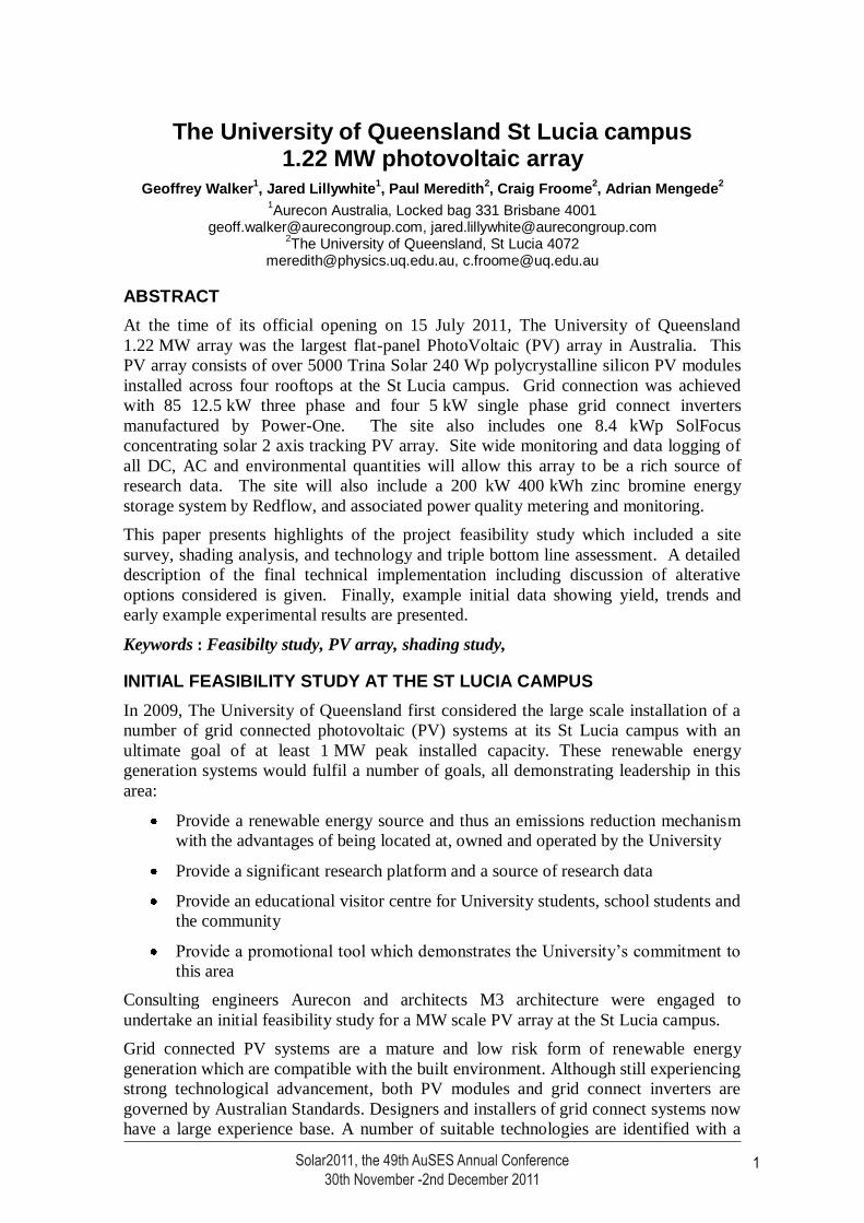
The University of Queensland St Lucia campus 1.22 MW photovoltaic array
Geoffrey Walker1, Jared Lillywhite
1, Paul Meredith
2, Craig Froome
2, Adrian Mengede
2
1Aurecon Australia, Locked bag 331 Brisbane 4001
[email protected], [email protected] 2The University of Queensland, St Lucia 4072
[email protected], [email protected]
ABSTRACT
At the time of its official opening on 15 July 2011, The University of Queensland
1.22 MW array was the largest flat-panel PhotoVoltaic (PV) array in Australia. This
PV array consists of over 5000 Trina Solar 240 Wp polycrystalline silicon PV modules
installed across four rooftops at the St Lucia campus. Grid connection was achieved
with 85 12.5 kW three phase and four 5 kW single phase grid connect inverters
manufactured by Power-One. The site also includes one 8.4 kWp SolFocus
concentrating solar 2 axis tracking PV array. Site wide monitoring and data logging of
all DC, AC and environmental quantities will allow this array to be a rich source of
research data. The site will also include a 200 kW 400 kWh zinc bromine energy
storage system by Redflow, and associated power quality metering and monitoring.
This paper presents highlights of the project feasibility study which included a site
survey, shading analysis, and technology and triple bottom line assessment. A detailed
description of the final technical implementation including discussion of alterative
options considered is given. Finally, example initial data showing yield, trends and
early example experimental results are presented.
Keywords : Feasibilty study, PV array, shading study,
INITIAL FEASIBILITY STUDY AT THE ST LUCIA CAMPUS
In 2009, The University of Queensland first considered the large scale installation of a
number of grid connected photovoltaic (PV) systems at its St Lucia campus with an
ultimate goal of at least 1 MW peak installed capacity. These renewable energy
generation systems would fulfil a number of goals, all demonstrating leadership in this
area:
Provide a renewable energy source and thus an emissions reduction mechanism
with the advantages of being located at, owned and operated by the University
Provide a significant research platform and a source of research data
Provide an educational visitor centre for University students, school students and
the community
Provide a promotional tool which demonstrates the University’s commitment to
this area
Consulting engineers Aurecon and architects M3 architecture were engaged to
undertake an initial feasibility study for a MW scale PV array at the St Lucia campus.
Grid connected PV systems are a mature and low risk form of renewable energy
generation which are compatible with the built environment. Although still experiencing
strong technological advancement, both PV modules and grid connect inverters are
governed by Australian Standards. Designers and installers of grid connect systems now
have a large experience base. A number of suitable technologies are identified with a
Solar2011, the 49th AuSES Annual Conference30th November -2nd December 2011
1
Solar2011, the 49th AuSES Annual Conference 30 November -2 December 2011
2
recommendation to stay with a proven combination of mono or polycrystalline silicon
PV modules and distributed string inverters, both chosen from the Business Council of
Sustainable Energy (BCSE) lists of approved modules and inverters.
Case studies of recent (as of 2010) large grid connect PV systems were presented,
including the Adelaide Showgrounds (2009-10, 1 MWp), the Crown Plaza in Alice
Springs (2009, 305 kWp), the Cadbury Schweppes factory, Huntingwood NSW (2008,
100 kWp) and the Adelaide Central bus station (2008, 50 kWp). These systems, along
with the pricing advice sourced from a number of large industry suppliers and installers,
suggested a (conservative) installed system price of 8-9 $/Wp installed capacity for a
large system of 100-500 kWp. This cost was predicted to fluctuate based on demand
and Australia’s exchange rate, but with a longer term downward trend. The final
installed cost of the UQ PV array was indeed lower than $8/Wp, as the cost of large
commercial rooftop installations has fallen significantly over the last two year period.
The overall project cost was also noted to be dependent on associated upgrade costs of
existing electrical and structural infrastructure, which could see the installed price
typically increase by a further 1-2 $/Wp. This highlighted the need for a site selection
exercise.
Initial short listing of sites based on suitability of roofs
Several criteria were used to elevate or indeed eliminate buildings as potential PV array
mounting sites. These criteria included (not in a strict order of importance):
potential area usable for array and thus expected power output
likely orientation and tilt of array (correlated to roof orientation)
shading from adjacent buildings, trees or other un-modelled objects, and future
buildings
access to building electrical switchboards and location of substation transformers
structural, waterproofing, and building condition issues
aesthetics, and heritage status of buildings
consideration of campus master-planning
a glare study
public, research and maintenance access
security and vandalism issues
An initial desktop review using aerial photographic and site plan drawings followed by
a site inspection tour created a large ranked selection list of buildings. Further
consultation with stakeholders and detailed shading analysis was used to refine the list
to create a short list for presentation to the University in the feasibility study.
Shading analysis
Even minor shading can cause a very significant reduction in the output of a PV array,
depending on the PV module technology and array wiring configuration. Predicting and,
as far as practical, avoiding any shading of PV arrays is an important part of site
selection and array layout.
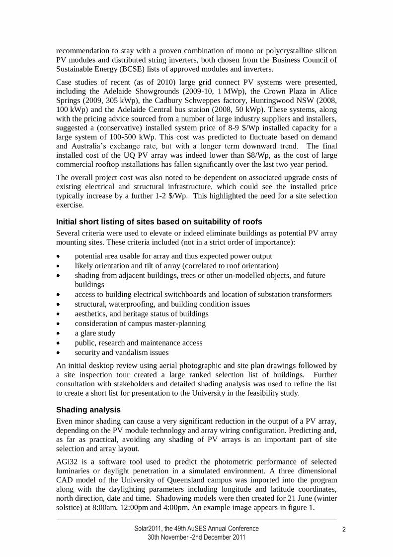
AGi32 is a software tool used to predict the photometric performance of selected
luminaries or daylight penetration in a simulated environment. A three dimensional
CAD model of the University of Queensland campus was imported into the program
along with the daylighting parameters including longitude and latitude coordinates,
north direction, date and time. Shadowing models were then created for 21 June (winter
solstice) at 8:00am, 12:00pm and 4:00pm. An example image appears in figure 1.
Solar2011, the 49th AuSES Annual Conference30th November -2nd December 2011
2
Solar2011, the 49th AuSES Annual Conference 30 November -2 December 2011
3
The modelled output produced shadowing from adjacent buildings and self shadowing
from plant rooms and different roof elevations. Vegetation, street lighting poles and
other roof plant structures such as antennas were not in the 3D CAD model and
additional assessment through a site inspection was required to check for their possible
shading impact. Possible future building works were also taken into consideration.
Figure 1 Daylight model of Hawken building showing the shadowing from adjacent
Chemistry building to the NW at 4pm in June
Electrical and structural suitability of sites
With a peak demand of approximately 20 MW, the University’s St Lucia campus has its
own extensive 11 kV electricity network. Major buildings are supplied by dedicated
substations, while in other areas substations supply LV to several buildings within each
precinct. Part of the selection process was to consider the spare capacity of existing
building switchboards where suitable, or the requirement for new switchboards, and the
proximity of substation transformers.
Likewise, the structural adequacy of building roofs were reviewed at a high level to
ensure their likely ability to support a significant amount of PV. This also included a
review of the pros and cons of tilting module framing (with the additional associated
wind loading) versus flat mounting. As part of the finalisation of the selected buildings,
a more detailed structural review was undertaken.
Final building selection
Several suitable sites were identified on the St Lucia Campus following an extensive
selection process. For bulk generation of renewable electricity, three buildings stood
out; the multistorey carparks (98A and 98B) and the UQ centre (27A). If high efficiency
(18%) monocrystalline modules were specified, these three buildings alone could
achieve the briefed goal with an estimated combined installed capacity of over
1.1 MWp. Carpark 98C was recommended but not adopted for visual and master-
Solar2011, the 49th AuSES Annual Conference30th November -2nd December 2011
3
Solar2011, the 49th AuSES Annual Conference 30 November -2 December 2011
4
planning reasons. Once lower efficiency modules were chosen, the Sir Llew Edwards
building (14) which already had a 10 kW test array was later chosen to accept additional
PV as part of the 1.22 MW PV array project.
Some buildings located within the engineering precinct were identified for research
focused PV installations. This area is currently undergoing substantial change as part of
the consolidation of engineering in its current location. Four options were short-listed,
each with quite different characteristics. However due to construction and
refurbishment works underway in that precinct, these sites were not considered further
for inclusion in the 1.22 MW PV array project. These buildings under (re)development
do offer an excellent opportunity to integrate additional accessible and flexible PV
research facility on their rooftops and this is will be considered as part of those
individual projects as they progress.
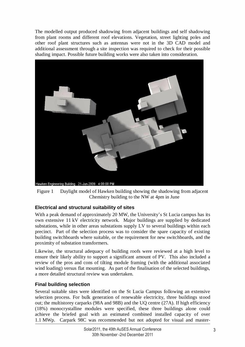
Figure 2: Site map of the University of Queensland, St Lucia indicating preferred
building roofs recommended for photovoltaic array installation
Two main options were considered for the public access facility as it was originally
envisaged. The first was to integrate a visitor centre with a Research and Development
facility in the engineering precinct. This has the advantage of allowing members of the
broader community of learning access to what is happening in this field. The second
was to integrate the PV Visitor Centre where the majority of the panels are located, that
is the Multi-Storey carparks or the UQ Centre, with the opportunity of a viewing
platform to achieve what would be impressive views across the arrays.
The final location of the PV visitor centre is in close proximity to the UQ centre in the
newly developed UQ Global Change Institute. This facility houses data visualisation
screens and associated computer access, sample panels and inverters, and other
interpretive media.
Carpark 98C
Multi-storey carparks
98B, 98A
UQ Centre 27A
AEB
Mansergh Shaw
Hawken
Axon
Sir Llew Edwards Bldg 14
Solar2011, the 49th AuSES Annual Conference30th November -2nd December 2011
4
Solar2011, the 49th AuSES Annual Conference 30 November -2 December 2011
5
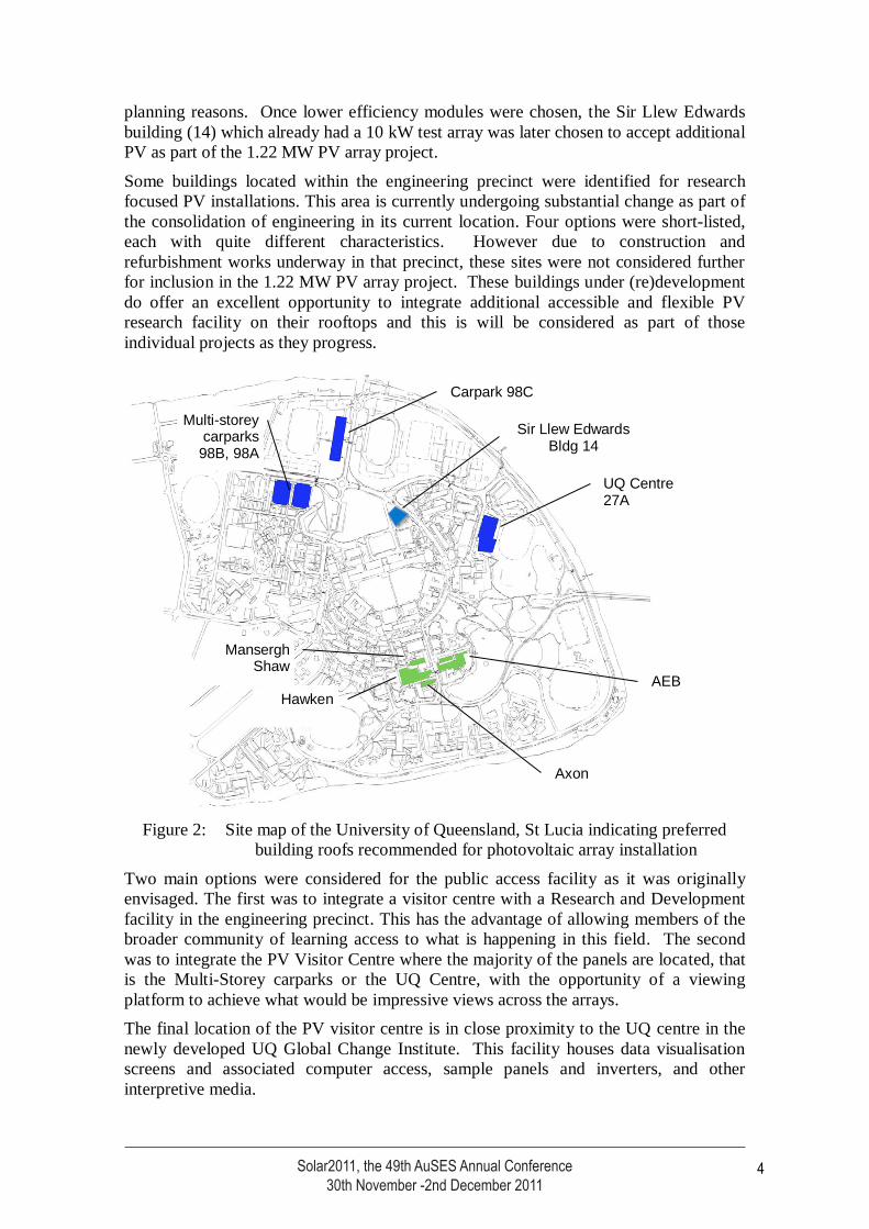
Figure 3: Aerial view looking west of the completed PV arrays. The multistorey
carparks (98B&A, foreground), Sir Llew Edwards building (14, centre) and
UQ centre (27A, back) are all visible.
The feasibility study did touch on possible revenue streams from the PV array. Because
of the University’s relatively low energy purchase prices, the reduction in electricity
consumption generates only modest income. The value and potential use of the (at the
time) Renewable Energy Certificates (RECs) which would be generated was also
discussed. This section of the study highlighted to all parties that while revenue streams
were of course important, a holistic approach to valuing the PV array was appropriate.
2. PV ARRAY ARCHITECTURE
PV module selection
As part of the feasibility study, a review of the current state of the PV module
technology was undertaken. Subsequently a minimum performance specification was
written. The University of Queensland then approached a number of PV module
manufacturers as part of the procurement process, seeking a future research partnership
as well as a high quality product and a good value proposition.
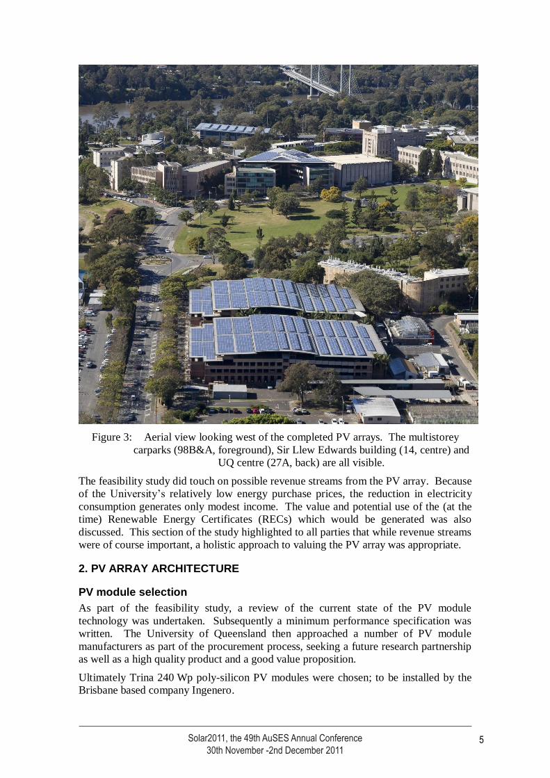
Ultimately Trina 240 Wp poly-silicon PV modules were chosen; to be installed by the
Brisbane based company Ingenero.
Solar2011, the 49th AuSES Annual Conference30th November -2nd December 2011
5
Solar2011, the 49th AuSES Annual Conference 30 November -2 December 2011
6
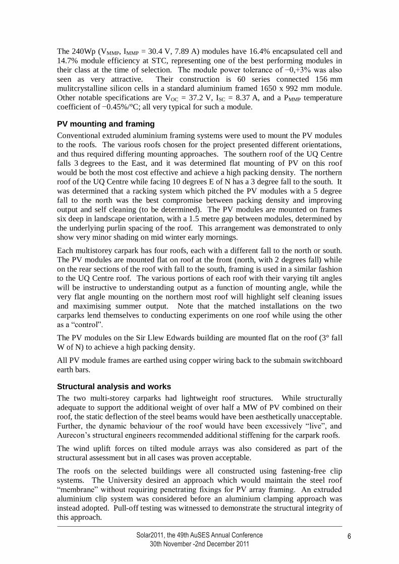
The 240Wp (VMMP, IMMP = 30.4 V, 7.89 A) modules have 16.4% encapsulated cell and
14.7% module efficiency at STC, representing one of the best performing modules in
their class at the time of selection. The module power tolerance of −0,+3% was also
seen as very attractive. Their construction is 60 series connected 156 mm
mulitcrystalline silicon cells in a standard aluminium framed 1650 x 992 mm module.
Other notable specifications are VOC = 37.2 V, ISC = 8.37 A, and a PMMP temperature
coefficient of −0.45%/°C; all very typical for such a module.
PV mounting and framing
Conventional extruded aluminium framing systems were used to mount the PV modules
to the roofs. The various roofs chosen for the project presented different orientations,
and thus required differing mounting approaches. The southern roof of the UQ Centre
falls 3 degrees to the East, and it was determined flat mounting of PV on this roof
would be both the most cost effective and achieve a high packing density. The northern
roof of the UQ Centre while facing 10 degrees E of N has a 3 degree fall to the south. It
was determined that a racking system which pitched the PV modules with a 5 degree
fall to the north was the best compromise between packing density and improving
output and self cleaning (to be determined). The PV modules are mounted on frames
six deep in landscape orientation, with a 1.5 metre gap between modules, determined by
the underlying purlin spacing of the roof. This arrangement was demonstrated to only
show very minor shading on mid winter early mornings.
Each multistorey carpark has four roofs, each with a different fall to the north or south.
The PV modules are mounted flat on roof at the front (north, with 2 degrees fall) while
on the rear sections of the roof with fall to the south, framing is used in a similar fashion
to the UQ Centre roof. The various portions of each roof with their varying tilt angles
will be instructive to understanding output as a function of mounting angle, while the
very flat angle mounting on the northern most roof will highlight self cleaning issues
and maximising summer output. Note that the matched installations on the two
carparks lend themselves to conducting experiments on one roof while using the other
as a “control”.
The PV modules on the Sir Llew Edwards building are mounted flat on the roof (3° fall
W of N) to achieve a high packing density.
All PV module frames are earthed using copper wiring back to the submain switchboard
earth bars.
Structural analysis and works
The two multi-storey carparks had lightweight roof structures. While structurally
adequate to support the additional weight of over half a MW of PV combined on their
roof, the static deflection of the steel beams would have been aesthetically unacceptable.
Further, the dynamic behaviour of the roof would have been excessively “live”, and
Aurecon’s structural engineers recommended additional stiffening for the carpark roofs.
The wind uplift forces on tilted module arrays was also considered as part of the
structural assessment but in all cases was proven acceptable.
The roofs on the selected buildings were all constructed using fastening-free clip
systems. The University desired an approach which would maintain the steel roof
“membrane” without requiring penetrating fixings for PV array framing. An extruded
aluminium clip system was considered before an aluminium clamping approach was
instead adopted. Pull-off testing was witnessed to demonstrate the structural integrity of
this approach.
Solar2011, the 49th AuSES Annual Conference30th November -2nd December 2011
6
Solar2011, the 49th AuSES Annual Conference 30 November -2 December 2011
7
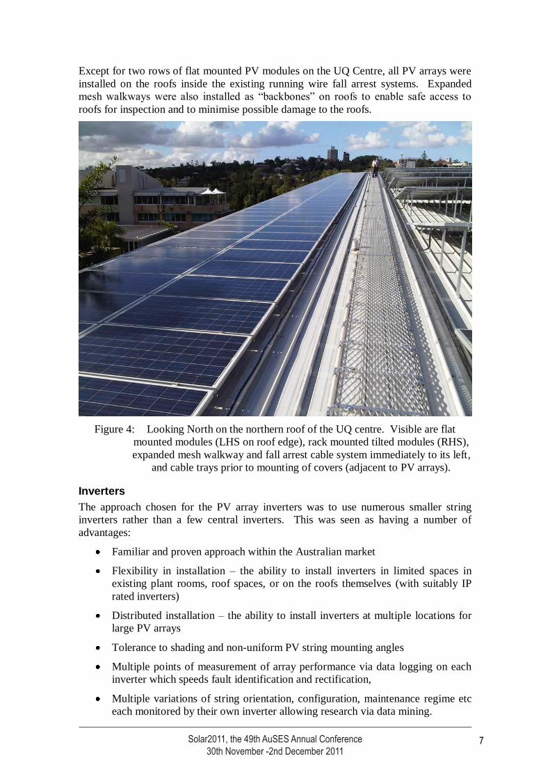
Except for two rows of flat mounted PV modules on the UQ Centre, all PV arrays were
installed on the roofs inside the existing running wire fall arrest systems. Expanded
mesh walkways were also installed as “backbones” on roofs to enable safe access to
roofs for inspection and to minimise possible damage to the roofs.
Figure 4: Looking North on the northern roof of the UQ centre. Visible are flat
mounted modules (LHS on roof edge), rack mounted tilted modules (RHS),
expanded mesh walkway and fall arrest cable system immediately to its left,
and cable trays prior to mounting of covers (adjacent to PV arrays).
Inverters
The approach chosen for the PV array inverters was to use numerous smaller string
inverters rather than a few central inverters. This was seen as having a number of
advantages:
Familiar and proven approach within the Australian market
Flexibility in installation – the ability to install inverters in limited spaces in
existing plant rooms, roof spaces, or on the roofs themselves (with suitably IP
rated inverters)
Distributed installation – the ability to install inverters at multiple locations for
large PV arrays
Tolerance to shading and non-uniform PV string mounting angles
Multiple points of measurement of array performance via data logging on each
inverter which speeds fault identification and rectification,
Multiple variations of string orientation, configuration, maintenance regime etc
each monitored by their own inverter allowing research via data mining.
Solar2011, the 49th AuSES Annual Conference30th November -2nd December 2011
7
Solar2011, the 49th AuSES Annual Conference 30 November -2 December 2011
8
High overall system reliability – a failure of a single inverter only marginally
reduces output.
Relatively low cost of individual inverters permits keeping spares
Large three phase transformerless string inverters were specified where possible to keep
the number of inverters to a manageable number and to ensure balanced three phase
outputs. The Power-One Aurora PVI-12.5-OUTD 12.5 kW inverters were offered and
accepted. These inverters offered the follow desirable features
Three phase balanced output
Transformerless, high efficiency over a wide power operating range (typically
>97%), with low standby (10 W) and overnight (<1W) losses – important with a
total inverter count of over 80.
Two MPPT inputs per inverter of equal power rating, capable of accepting up to
18 A each (two or three input strings each depending on cell size).
Passively cooled, with an IP65 rating.
Anti-islanding protection (as required by AS4777) and DC side earth leakage
detection.
Extensive input (DC) and output (AC) data measurement and telemetry built in.
The input ratings of the inverters allowed two parallel PV strings of up to 15 PV
modules each to be connected to each MPPT input, for a maximum of 60 PV modules
per inverter. By limiting the maximum paralleling of PV module strings to only two
parallel strings, no DC side fusing was required. DC side disconnection was integrated
into the inverters using a multipole switch. This approach also avoided the additional
space and expense of a DC combiner box or switchboard.
Each PV module string wiring was separately run down to the inverters, with no string
paralleling occurring on the roof, but only at the inverter inputs. This was done to allow
maximum flexibility for future reconfiguration and monitoring of string circuits. Each
inverter MPPT input monitors every two parallel strings. All cabling is supported in
covered cable trays via minimum 4 sqmm solar cable. All DC wiring was by design
and subsequent specification chosen to limit voltage drop and thus losses to less than
1% for any circuit.
A deliberate choice was made to avoid the use of any DC breakers, disconnectors or
fuses on the roof top array for reasons of reliability. If disconnection is required of
individual strings on the roof, this can be safely achieved using the touch proof
connectors once a suitable de-energisation and disconnection process is observed at the
inverter. This was considered safe in the controlled environment of the University
roofs.
With up to sixty 240Wp PV modules per inverter, the inverters were theoretically
loaded to 14400W. The maximum recommended DC input power was 14.3 kW,
however, given the power derating of PV modules at typical operating temperatures of
20-30°C rise above standard test conditions (STC), this is not considered unreasonable.
A review of several months of five minute PV data from an existing UQ PV research
array suggested the amount of power forfeited would be extremely small and certainly
less than <1%. Various 12.5 kW inverters have been configured with 56, 58 and 60 PV
modules, and their temperature rise and future potential power limiting will be
monitored. This is just one example of the experimental opportunities offered by the
array by design.
Solar2011, the 49th AuSES Annual Conference30th November -2nd December 2011
8
Solar2011, the 49th AuSES Annual Conference 30 November -2 December 2011
9
Six 5 kW single phase Aurora PVI-5-OUTD inverters were also used across the entire
array to cope with the balance of modules which occurred on each roof.
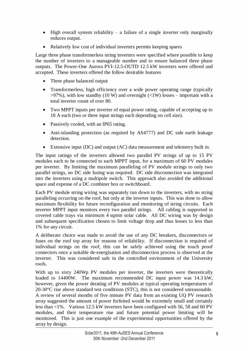
The inverters are variously mounted indoors in naturally ventilated mezzanine spaces
and plant-rooms (UQ Centre), outdoors but under cover in purpose built open air
“rooms” (multistorey carparks) and outdoors, shaded but otherwise exposed on the roof
(Sir Llew Edwards Building).
Figure 5: Aurora 12.5 kW three phase inverters were mounted inside (UQ centre, left)
or undercover in open rooms (carparks, right). Segregated DC and AC
cabling is evident, with each DC string cable brought to the inverters for
flexibility.
On the three largest sites, all inverter AC connections were brought back to dedicated
sub-main switchboards which had been installed for the project. In the UQ Centre,
these were supplied by spare breakers on the main building switchboard. In the two
multistorey car parks, new dedicated main switchboards and cabling back to the local
HV substation was required. As part of this work, future capacity has been allowed in
the carpark switchboards for the provision of EV charging, and a dedicated circuit and
metering was installed for the Redflow energy storage experiment.
As for the DC wiring, all AC wiring was by design and subsequent specification chosen
to limit voltage drop and thus losses to less than 1% for any circuit. This was also
considered important on the AC side to limit the voltage rise at the inverter terminals
and thus avoid unexpected inverter tripping on overvoltage.
AC side metering was installed on the submain switchboard incoming circuits. The
chosen meters are by default configured to log on 1 minute intervals. Live and
historical array data is displayed on a dedicated webpage, and will be made available for
download. Two examples of instantaneous output data are presented in figure 6.
Solar2011, the 49th AuSES Annual Conference30th November -2nd December 2011
9
Solar2011, the 49th AuSES Annual Conference 30 November -2 December 2011
10
4. PERFORMANCE AND SUMMARY
At the time of its official opening on 15 July 2011, The University of Queensland
1.22 MW array was the largest PV array in Australia.
Table 1: Summary of the installed components of the combined 1.22 MW PV array.
Site name, bldg. no. Trina 240Wp
Modules
Aurora 12.5 &
5kW inverters
Total installed kW
Carpark 98A 1412 24 & 2 338.88
Carpark 98A 1412 24 & 2 338.88
UQ Centre 27A 1806 31 & 1 433.44
Sir Llew Edwards 14 374 6 & 1 89.76
Sir Llew Edwards 14 6 research arrays,
64 modules
6 x 3kW Fronius
WR3300
10.19
SolFocus tracker 1 x SF-1100S 1 x 10kW PVI-10 8.4
Solyndra array 12 x 173W 1.7kW Aurora 2.08
Total 5004 + others 85, 6 + others 1221.44
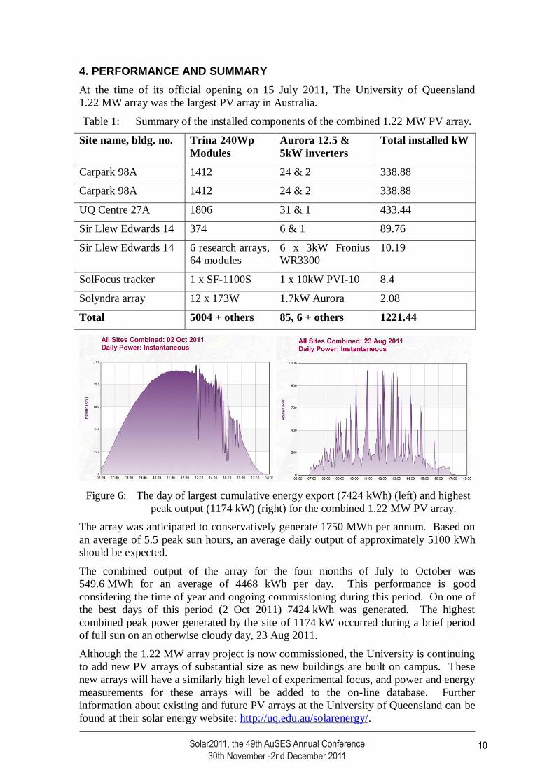
Figure 6: The day of largest cumulative energy export (7424 kWh) (left) and highest
peak output (1174 kW) (right) for the combined 1.22 MW PV array.
The array was anticipated to conservatively generate 1750 MWh per annum. Based on
an average of 5.5 peak sun hours, an average daily output of approximately 5100 kWh
should be expected.
The combined output of the array for the four months of July to October was
549.6 MWh for an average of 4468 kWh per day. This performance is good
considering the time of year and ongoing commissioning during this period. On one of
the best days of this period (2 Oct 2011) 7424 kWh was generated. The highest
combined peak power generated by the site of 1174 kW occurred during a brief period
of full sun on an otherwise cloudy day, 23 Aug 2011.
Although the 1.22 MW array project is now commissioned, the University is continuing
to add new PV arrays of substantial size as new buildings are built on campus. These
new arrays will have a similarly high level of experimental focus, and power and energy
measurements for these arrays will be added to the on-line database. Further
information about existing and future PV arrays at the University of Queensland can be
found at their solar energy website: http://uq.edu.au/solarenergy/.
Solar2011, the 49th AuSES Annual Conference30th November -2nd December 2011
10