Embed Size (px)
Citation preview

Predicting Wellbore Dynamic-Shock Loads Prior to Perforating SPE 143787Loads Prior to Perforating SPE 143787
Jack Burman/Exploitation Technologies, LLC/SPE;
Martin Schoener-Scott, Cam Le, and David Suire/Halliburton/SPE

Agenda
� Software Overview
� Validation Example
2© 2011 HALLIBURTON. ALL RIGHTS RESERVED.
� Case Histories
� Comparing the Cases
� Conclusions
MENAPS-11-18

Dynamic -Shock Modeling Software
� Simulation software that focuses on dynamic loading of tubulars, packers, casing and other completion equipment.
3© 2011 HALLIBURTON. ALL RIGHTS RESERVED.
� Inception– 2003– SPE 90042
MENAPS-11-18

Other SPE Papers
SPE 144059
4© 2011 HALLIBURTON. ALL RIGHTS RESERVED.
OTC 21059MENAPS-11-18

Physics Based Model
Wellbore
Possible Surface Over or Under-Pressure� Tool burn
� Navier-Stokes equation– transient mixed-phase
compressible fluid flow in well
� Transient Bernoulli– choke flow for perfs
� Fracture mechanics
Tubing,Packers, etc.
5© 2011 HALLIBURTON. ALL RIGHTS RESERVED.
Fluid motion in Well, Tubing
Energized Zone
WellboreFluids
Fluid Motion In/Out of Perfs/FracsEnergy
Source (PerfGun)
Basic Wellbore Geometry
� Fracture mechanics– frac initiation and propagation
� Wave equation– elastic solids in equipment
string
� Transient layered Darcy flow
– formation
MENAPS-11-18

Dynamic Failure Modes
Packer- Axial Loads- Differential Failure
Tubing- Comp and Tension- Burst and Collapse- Bending
6© 2011 HALLIBURTON. ALL RIGHTS RESERVED.
Guns- Comp and Tension- Burst and Collapse
Bridge Plug/Sump- Axial Loads- Differential Failure
Casing- Burst
MENAPS-11-18
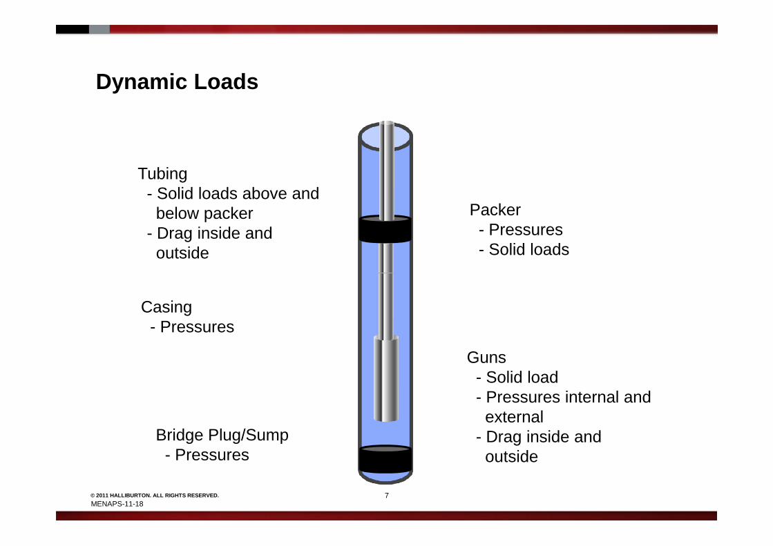
Dynamic Loads
Packer- Pressures- Solid loads
Tubing- Solid loads above andbelow packer
- Drag inside andoutside
7© 2011 HALLIBURTON. ALL RIGHTS RESERVED.
Guns- Solid load- Pressures internal andexternal
- Drag inside andoutside
Bridge Plug/Sump- Pressures
Casing- Pressures
MENAPS-11-18

Validation ExampleModel Matching – New Gun SystemModel Matching – New Gun System
MENAPS-11-18
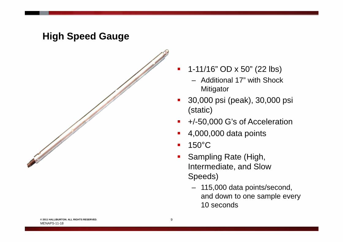
High Speed Gauge
� 1-11/16” OD x 50” (22 lbs)– Additional 17” with Shock
Mitigator
� 30,000 psi (peak), 30,000 psi (static)
� +/-50,000 G’s of Acceleration
9© 2011 HALLIBURTON. ALL RIGHTS RESERVED.
� +/-50,000 G’s of Acceleration� 4,000,000 data points� 150°C� Sampling Rate (High,
Intermediate, and Slow Speeds)– 115,000 data points/second,
and down to one sample every 10 seconds
MENAPS-11-18

5 ¾” 18spf HSD Mirage RDX
� What dynamic loads are to be expected during
10© 2011 HALLIBURTON. ALL RIGHTS RESERVED.
� What dynamic loads are to be expected during gun detonation?
MENAPS-11-18

Well 1
11© 2011 HALLIBURTON. ALL RIGHTS RESERVED.
• Initial overlay with original geometry
MENAPS-11-18

Well 1
12© 2011 HALLIBURTON. ALL RIGHTS RESERVED.
• Overlay with update geometry
MENAPS-11-18

Well 1
13© 2011 HALLIBURTON. ALL RIGHTS RESERVED.
• Overlay with adjusted gun remnant and permeability
MENAPS-11-18

Well 2
14© 2011 HALLIBURTON. ALL RIGHTS RESERVED.
• Initial overlay
MENAPS-11-18

Well 2
15© 2011 HALLIBURTON. ALL RIGHTS RESERVED.
• Overlay with adjusted gun remnant and permeability from well 1
MENAPS-11-18

Well 1
257 kips downward
Pre-Job Model Post-Job Model
206 kips downward
16© 2011 HALLIBURTON. ALL RIGHTS RESERVED.
395 kips upward
273 kips upward
MENAPS-11-18

Well 2Pre-Job Model Post-Job Model
174 kips downward138 kips downward
17© 2011 HALLIBURTON. ALL RIGHTS RESERVED.
391 kips upward
273 kips upward
MENAPS-11-18

Lessons Learn
� New gun system characteristic of retaining explosive energy in these conditions
� Loads were over predicted in initial models– Longer gun assembles can be run without much
18© 2011 HALLIBURTON. ALL RIGHTS RESERVED.
– Longer gun assembles can be run without much concern
� To match FastGauge Data in late time adjustment to perm was require to match the actual reservoir response– Confirm by feedback from customer's production data
MENAPS-11-18

Case HistoriesCase Histories
MENAPS-11-18
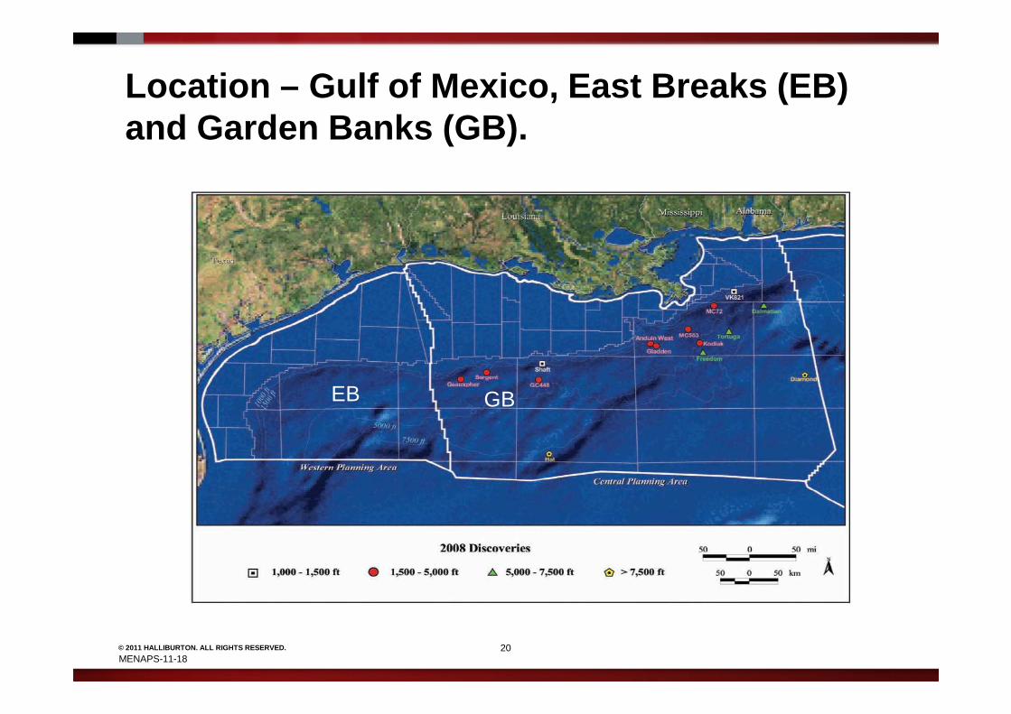
Location – Gulf of Mexico, East Breaks (EB) and Garden Banks (GB).
20© 2011 HALLIBURTON. ALL RIGHTS RESERVED.
Geographic distribution of 2008 discoveries by wate r depthhttp://www.gomr.boemre.gov/PDFs/2009/2009-016.pdf
EB GB
MENAPS-11-18

Shrouded Firing Head
Time Delayed Firing HeadHigh Strength Shroud
21© 2011 HALLIBURTON. ALL RIGHTS RESERVED.
6 ½” Gun System 14spf
Double Pin Connector
MENAPS-11-18
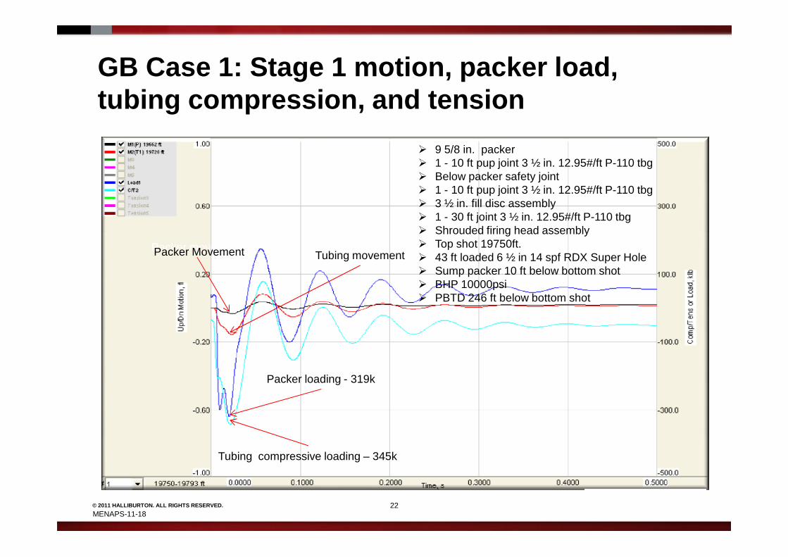
GB Case 1: Stage 1 motion, packer load, tubing compression, and tension
Packer movementTubing movement
� 9 5/8 in. packer� 1 - 10 ft pup joint 3 ½ in. 12.95#/ft P-110 tbg� Below packer safety joint� 1 - 10 ft pup joint 3 ½ in. 12.95#/ft P-110 tbg� 3 ½ in. fill disc assembly� 1 - 30 ft joint 3 ½ in. 12.95#/ft P-110 tbg� Shrouded firing head assembly� Top shot 19750ft.� 43 ft loaded 6 ½ in 14 spf RDX Super Hole� Sump packer 10 ft below bottom shot� BHP 10000psi
Packer Movement
22© 2011 HALLIBURTON. ALL RIGHTS RESERVED.
Tubing compressive loading – 345k
Packer loading - 319k
� BHP 10000psi� PBTD 246 ft below bottom shot
MENAPS-11-18

Case 1: Stage 1 pressure at specific locations (nodes) in the wellbore
Bottom perforations
� 9 5/8 in. packer� 1 - 10 ft pup joint 3 ½ in. 12.95#/ft P-110 tbg� Below packer safety joint � 1 - 10 ft pup joint 3 ½ in. 12.95#/ft P-110 tbg� 3 ½ in. fill disc assembly� 1 - 30 ft joint 3 ½ in. 12.95#/ft P-110 tbg� Shrouded firing head assembly� 43 ft loaded 6 ½ in 14 spf RDX Super Hole� Sump packer 10 ft below bottom shot� PBTD 246 ft below bottom shot
23© 2011 HALLIBURTON. ALL RIGHTS RESERVED.
Differential pressure at the packer – 1700psi
Top perforations
MENAPS-11-18

Case 1: Stage 1 average pressure in perforated interval
Peak pressure in perforated interval – 15268psi
Initial wellbore pressure
24© 2011 HALLIBURTON. ALL RIGHTS RESERVED.
Formation pressure
� 9 5/8 in. packer� 1 - 10 ft pup joint 3 ½ in. 12.95#/ft P-110 tbg� Below packer safety joint � 1 - 10 ft pup joint 3 ½ in. 12.95#/ft P-110 tbg� 3 ½ in. fill disc assembly� 1 - 30 ft joint 3 ½ in. 12.95#/ft P-110 tbg� Shrouded firing head assembly� 43 ft loaded 6 ½ in 14 spf RDX Super Hole� Sump packer 10 ft below bottom shot� PBTD 246 ft below bottom shot
MENAPS-11-18

GB Case 2: Stage 3 Iteration 2
25© 2011 HALLIBURTON. ALL RIGHTS RESERVED.
� 9 5/8 in. packer� 3 - 10 ft joint 3 ½ in. 12.95#/ft P-110 tubing� Below packer safety joint � 6 - 10 ft joint 3 ½ in. 12.95#/ft P-110 tubing� 3 ½ in. fill disc assembly� Shrouded firing head assembly� Top shot 21509ft� 60 ft loaded 6 ½ in. 14 spf RDX Super Hole � Frac pack packer 10 ft below bottom shot with packer plug installed
MENAPS-11-18

EB Case 3: Iteration 1 initial proposed BHA
� 9 5/8 in. packer� 1 - 10 ft pup joint 3 ½ in.12.95#/ft P-110 tbg� 3 ½ in. fill disc assembly� 1 - 30 ft joint 3 ½ in. 12.95#/ft P-110 tbg� Shrouded firing head assembly� Top shot 7500ft MD� 30 ft loaded 6 ½ in. 14 spf RDX Super Hole� PBTD 84 ft below bottom shot
26© 2011 HALLIBURTON. ALL RIGHTS RESERVED.
MENAPS-11-18
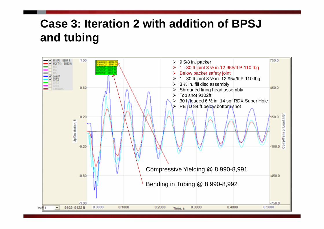
Case 3: Iteration 2 with addition of BPSJ and tubing
� 9 5/8 in. packer� 1 - 30 ft joint 3 ½ in.12.95#/ft P-110 tbg� Below packer safety joint� 1 - 30 ft joint 3 ½ in. 12.95#/ft P-110 tbg� 3 ½ in. fill disc assembly� Shrouded firing head assembly� Top shot 9102ft� 30 ft loaded 6 ½ in. 14 spf RDX Super Hole� PBTD 84 ft below bottom shot
27© 2011 HALLIBURTON. ALL RIGHTS RESERVED.
Compressive Yielding @ 8,990-8,991
Bending in Tubing @ 8,990-8,992

Case 3: Iteration 3 with additional 60 ft of tubing & all tubing joints where changed to 10 ft pup joints
28© 2011 HALLIBURTON. ALL RIGHTS RESERVED.
� 9 5/8 in. packer� 6 - 10 ft pup joint 3 ½ in.12.95#/ft P-110 tbg� Below packer safety joint� 3 - 10 ft pup joint 3 ½ in. 12.95#/ft P-110 tbg� 3 ½ in. fill disc assembly� 3 - 10 ft pup joint 3 ½ in. 12.95#/ft P-110 tbg� Shrouded firing head assembly� 30 ft loaded 6 ½ in. 14 spf RDX Super Hole� PBTD 84 ft below bottom shot

Slide 28
AS1 This doesn't seem clear.Adrienne Silvan, 5/5/2011

Comparing Case 1 Stage 1 with Case 3 Iteration 2:Pressures at Selected Nodes
21,600 psi15,400 psi
29© 2011 HALLIBURTON. ALL RIGHTS RESERVED.
3,200 psi differential at packer
1,700 psi differential at packer
Case 1 Stage 1 Case 3 Iteration 2MENAPS-11-18
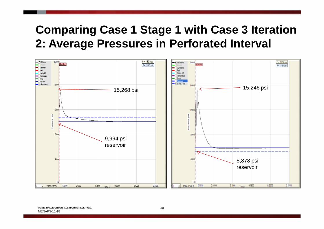
Comparing Case 1 Stage 1 with Case 3 Iteration 2: Average Pressures in Perforated Interval
15,246 psi15,268 psi
30© 2011 HALLIBURTON. ALL RIGHTS RESERVED.
Case 1 Stage 1 Case 3 Iteration 2
5,878 psi reservoir
9,994 psi reservoir
MENAPS-11-18
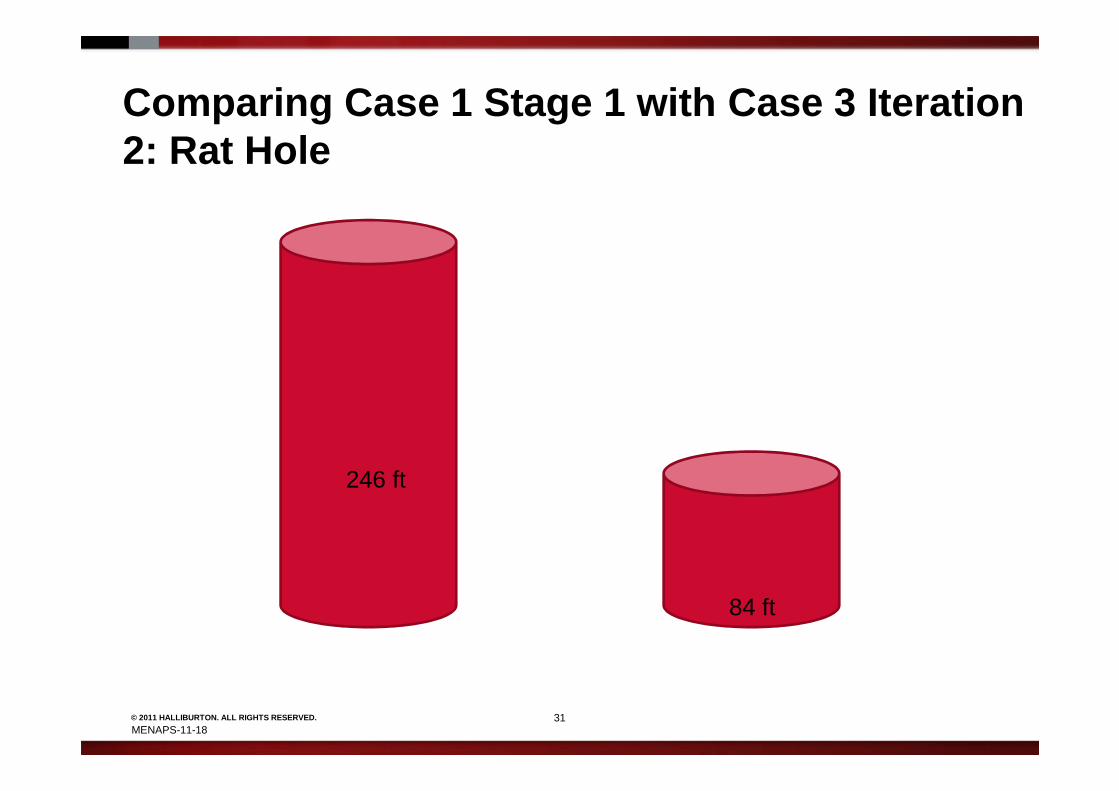
Comparing Case 1 Stage 1 with Case 3 Iteration 2: Rat Hole
31© 2011 HALLIBURTON. ALL RIGHTS RESERVED.
246 ft
84 ft
Case 1 Case 3
MENAPS-11-18

Comparing Case 1 Stage 1 with Case 3 Iteration 2: Summary
� Higher peak pressures
� Higher packer differential
32© 2011 HALLIBURTON. ALL RIGHTS RESERVED.
� Lower BHP
� Less rat hole volume
MENAPS-11-18

Conclusions
� An experienced modeler can predict dynamic behavior during a perforating event.
� Dynamic behavior is not always intuitive.
33© 2011 HALLIBURTON. ALL RIGHTS RESERVED.
� Dynamic behavior is not always intuitive.
� Eliminate potential problems before execution.
MENAPS-11-18

Burning Questions
34© 2011 HALLIBURTON. ALL RIGHTS RESERVED.
What Do You Think
MENAPS-11-18


![SPE 146559 - A Unique Plug for a Restricted Wellbore[1]The plug was drilled out with a motor and mill on coiled tubing, and an extensive coiled tubing wellbore cleanout followed the](https://img.pdfslide.us/doc/110x75/5e6e01222d25523d4c33a275/spe-146559-a-unique-plug-for-a-restricted-wellbore1-the-plug-was-drilled-out.jpg)