Embed Size (px)
Citation preview

1
Network Learning CentreProprietary & Confidential
11
MEN Part 1

Network Learning CentreProprietary & Confidential
22
Day 3
Module 4• STP• RSTP• MSTP
• Exercise
– MSTP – 2 labs– Bypass switch password– Loading IOS on Switch
Agenda

Network Learning CentreProprietary & Confidential
33
Module 4
Spanning Tree Protocol - STP

4
Network Learning CentreProprietary & Confidential
44Page 4
Applications Of Transparent Bridge
• Expand LAN scale• Free and dynamic learning of site address
information• Problem: frames or packets might be
forwarded circularly and continuously, resulting in network congestion
Transparent bridge can learn the address information of the sites by itself, thereby; it can effectively control the data flow on the network.
When a port of the bridge receives a frame containing the source MAC address, it will save the address and the receiving port in an address table, and the table will indicate that the MAC address is located in the network segment where the port is.
When the bridge receives a data frame, it will check the address table to find out the port corresponding to the destination address.
• If it is the receiving port, it will give up the frame; if it is not the receiving port, the frame will be forwarded at that port.
• If it cannot find out the port corresponding to the destination address of the received data frame, the data will be forwarded from all other ports except the port that received it.
•Moreover, if what the bridge received is a broadcast frame, the frame will be also forwarded from all other ports except the port that received it.
But, the problem is that the "transparent" bridge is not the router, it will not do any modification to the frame, and the frame will not record how many bridges has been passed; if a loop exists on the network, the message might circulate and increase continuously in the loop and cause the congestion of network. That’s the problem of “route loop”.

5
Network Learning CentreProprietary & Confidential
55Page 5
Broadcast In A Network With Loops
LAN 1LAN 1
LAN 2LAN 2
11
11 11 11
22 22 2233 3333
Site A
Site B
B1 B2 B3
In the figure, it is an example of the message circulation and proliferation caused by the route loop. It is assumed that Site A has not transmitted any packets, so, there is no record of Mac address of Site A in the address tables of the bridges: B1, B2 and B3. When Site A has transmitted a packet, all these three bridges have received the packet at beginning and recorded the address of Site A on LAN 1, and they are queuing to wait for forwarding the packet to LAN 2. Based on the rules of LAN, one of the bridges will successfully forward the packet to LAN 2 first of all. The bridge is assumed as B1, then, B2 and B3 will receive the packet once again; since B1 is transparent to B2 and B3, the packet is as if it is transmitted on LAN 2, and then, B2 and B3 will take the note as Site A is on LAN 2, and they will queue to wait for forwarding the new packet to LAN 1; and supposing, at the same time, B2 successfully forwards the original packet to LAN 2, then, both B1 and B3 will receive the packet; as to B3, it regards that Site A is still on LAN 2, but as to B1, it regards that Site A has been forwarded to LAN 2, thereafter, B1 and B3 will stand in a line to wait for forwarding the new packet to LAN 1. Thus, the packet recycles continuously in the loop, and the more awful is that the successfully transmitted packet will cause two new packets appearing on the network each time.

6
Network Learning CentreProprietary & Confidential
66Page 6
Why We Need Spanning Tree Protocol?
• Remove path loop that might exist in the bridging network by blocking redundant links
• Activate redundant backup links to restore network connection when the current active path fails
ROOTROOTLAN BLAN B
LAN CLAN C
LAN DLAN D
LAN ELAN ELAN ALAN A
Even though the hidden trouble exists in the transparent bridge, the application of transparent bridge is still alluring because the function exerted on the loop-free network by the transparent bridge is very useful. Does it mean that we cannot build up the network with loops, then? No. By all appearances, it is out of place; because the available loop can, however, guarantee the connectivity of network after a link of the Topology structure is disconnected.
Therefore, we find out a good algorithm that trims the bridge network with the loop into a tree topology structure without any loop via blocking the redundant link; it not only resolves the problem of loop but also can re-trim the topology structure to resume the connection of network via activating the blocked redundant link when an active link is disconnected.
After referring to the bridge network example of spanning tree in the figure, the basic concept of the algorithm should be explained very clear. The bridge marked with the word ROOT is the root of spanning tree, the real lines are active links, i.e. the branches of spanning tree; but the broken lines are redundant links, which will be enabled only when the active link is disconnected.

7
Network Learning CentreProprietary & Confidential
77Page 7
Basic Principle Of Spanning Tree Protocol
• Transmit BPDUs (Bridge Protocol Data Unit )among
network bridges and do the following jobs:
– Select the root.
– Calculate the shortest path.
– Select designated bridge.
– Select a root port.
– Select designated ports.
The basic theory of spanning tree algorithm is very simple. The special configuration messages are forwarded between the bridges, and they are called as “Bridge Protocol Data Unit (BPDU)" in the 802.1D protocol. The configuration messages contain sufficient information to ensure the bridge accomplishing the calculation of spanning tree.
1) In all the bridges involved in the calculation of the spanning tree on the bridge network, one of them will be selected as the Root Bridge;
2) Calculate the shortest route from other bridges to the Root Bridge;3) Specify a bridge among the bridges connected for each LAN, and the bridge
must be the closest one to the Root Bridge, which is responsible for transmitting the packet on the LAN to the Root Bridge;
4) Select a root port for each bridge, and the route given by that port is the shortest route from the bridge to the Root Bridge;
5) Select the port contained in the spanning tree, which consists of the root port and those designated ports of the designated bridges which are connected to the LANs.

8
Network Learning CentreProprietary & Confidential
88Page 8
Contents Of BPDU
• The content of BPDU is organized as (Root ID, Root
Path Cost, Designated Bridge ID, Designated Port ID)
– Root ID: Identifier of root
– Root Path Cost: The smallest path cost from the
designated bridge to the root
– Designated Bridge ID : Identifier of the designated
bridge
– Designated Port ID :Identifier of the
designated port
BPDU’s destination MAC address is a fixed multicast address, and all the bridges involved in the calculation of the spanning tree will receive the packet of the address; the data used for the spanning tree calculation is carried in the payload domain.
Initially, all the bridges transmit the configuration messages that take themselves as the root bridges, e.g. the bridge B1 transmits the configuration message as (B1,0, B1, Port ID).
The bridges will compare the received configuration messages with their own configuration messages in priority, and save the configuration message with higher priority and complete the spanning tree calculation according to the saved message.

9
Network Learning CentreProprietary & Confidential
99
Bridge ID Format
• STP Bridge ID Format– Priority + Vlan ID + MAC
Bridge id – 2 bytes priority + mac add as tie breaker

Network Learning CentreProprietary & Confidential
1010
• Default port cost– 10 MB – 100– 100 MB – 19– 1 Gbps – 4– 10 Gbps – 2
Port Cost (Cisco)
11
Network Learning CentreProprietary & Confidential
1111Page 11
Construct BPDU
• Select the best BPDU from all the BPDUs to construct its own BPDU.
– Select RootID: the RootID of the BPDU with the highest priority
– Calculate Root Path Cost:
• Root Path Cost is the sum of the Root Path Cost of best
BPDU and the cost of the port that receives this BPDU
– Select Root Port:
• The root port is the one that receives the best BPDU
– Select designated port: the ports used to forward the packets
• Send the new BPDU from a designated port
Then, how do we calculate the spanning tree on the basis of the priority?First, the root bridge with the smallest ID in the configuration message will be
the root of spanning tree;If the root bridge is itself, the overhead of the shortest route is 0; or, the shortest
route overhead from the bridge to the root is that the route overhead in the optimal configuration message pluses the route overhead of the link corresponding to the receiving port; Root Path Cost is 0 if it is the root itself
Then, select the root port. Usually, the root port is the port relevant to the shortest route overhead; the port with the smallest ID will be the root port if there are more than one port corresponding to the shortest route overhead. the root port is 0 if it is the root itself
After the root and the shortest route are determined, the bridges will obtain their own configuration messages (BPDU) and take themselves as the designated bridges for the ports from which the bridges have received BPDUs that are inferior to its own BPDU, and these ports are the designated ports.
The bridges will transmit their own configuration message from the designated ports.

12
Network Learning CentreProprietary & Confidential
1212Page 12
How To Determine The Best BPDU?
• The best BPDU has the high priority
– Assume there are two configuration messages C1 and C2, then:
• According to Root ID
• If above is the same, According to the Root Path Cost
• If above are the same, According to the Designated Bridge ID
• If above are the same, According to the Port ID
Principle : the smaller, the better
The comparison principles of configuration message priority are:First, compare the IDs of root bridges; the smaller ID the higher priority.If the IDs of root bridges are the same, the shortest routes from the transmission
bridges to the root bridges, that is, the RootPathCost will be compared, and the smaller value the higher priority.
If both above are the same, the IDs of the transmission bridges will be compared, the smaller value the higher priority;
Last, if the above three are the same, the IDs of transmission ports will be compared, the smaller value the higher priority.
What requires explaining is that the two ports of the transmission bridges are connected to one physical LAN if the above three are the same.

13
Network Learning CentreProprietary & Confidential
1313
Spanning Tree AlgorithmSpanning Tree Algorithm
• Using redundant Bridges, for higher network reliability, causes looping of frames. STA is used to avoid such looping.• STA detects frame looping and puts one of the two redundant Bridges into Standby mode.• Bridges develop and maintain a map of the network topology by exchanging bridge protocol data units (BPDUs).
Root switch – least bridge id wins….id is priority + mac, this is unique
RP – least cost in Hello packet
if there are same cost from multiple Hellos, tiebreaker is
- lower forwarding switch bridge id
- lowest port priority of forwarding switch
- lowest port number of forwarding switch
BPDUs contain the following information:
• Protocol ID—Defines this packet as a BPDU.
• Version—The current version used by this BPDU packet.
• Message Type—Indicates the stage of the negotiation.
• Flags.Used to indicate a topology change.
• Root ID.A number composed of the assigned bridge priority (most significant two octets) followed by the bridge MAC address.
• Root cost.Cost of the total path to the root bridge from the bridge sending the BPDU.
• Bridge ID.ID of the bridge sending the BPDU; actually composed of the bridge priority (2 bytes) and the bridge MAC address (6 bytes).
• Port ID Made up of the configured port priority (most significant octet) and the interface

14
Network Learning CentreProprietary & Confidential
1414Page 14
An Instance Of Receiving And Calculating BPDU
Port 1Port 1
Port 2Port 2Port 3Port 3 Port 4Port 4
Port 5Port 5
B81B81
LAN ALAN A
B23B23RootRoot
B80B80B100B100B321B321
B32B32
B123B123
B102B1021717
1313
1313
1313
This Instance can tell us how to calculate BPDU after receiving it. In the convergent network, bridge B23 is selected as the root bridge,when B81 joins the network ,the topology will change ,so the spanning tree will calculate again.

15
Network Learning CentreProprietary & Confidential
1515Page 15
An Instance Of Receiving And Calculating BPDU
• Select Port4 as the root ,select Port1 and Port2 as designated ports, and meanwhile block Port3 and Port5.
• Send new BPDU from Port1 and Port2: (23, 15, 81)– Root ID = 23– Root Path Cost = 14+1 = 15– Root Port ID = Port4– Designated Bridge ID=81
Port 1Port 1Port 2Port 2 Port 3Port 3 Port 4Port 4
Port 5Port 5
blockingblockingblockingblocking
3232,,00,,3232 2323,,1818,,123123 2323,,1414,,321321 2323,,1414,,100100 2323,,1515,,80 80
rootroot
2323,,1515,,8181
B81B81
2323,,1515,,8181
Below, we will give an example to explain the process. The bridge B81 in the figure has 5 ports in total, which separately receive such configuration messages:Port 1: (32, 0, 32)Port 2: (23, 18, 123)Port 3: (23, 14, 321)Port 4: (23, 14, 100)Port 5: (23, 15, 80)
After the PRIORITY comparison, the B23 will be determined as the best root bridge; the shortest route from the bridge to root bridge is 14+1=15. The bridge must select a port as the root port from Port 3 and Port 4, and Port 4 will be the root port since the transmission bridge's ID of Port 4 configuration message is 111 and smaller than 315 of Port 3.
The bridge 81 will transmit the configuration message (23,15,81), which is precedence over the configuration messages received by Port 1 and Port 2, so, the bridge 81 is the designated bridge of the network segment connected by Port 1 and Port 2, and it will transmit its own configuration message from Port 1 and Port 2.
Thus, it is determined to block Port 3 and Port 5, Port 4 is the root port, and Port 1 and Port 2 are the designated ports. The blocked port will not join in transferring data, and the data that are received by the root port and the designated port and need to be forwarded only can be forwarded from other root ports or other designated ports.
From the point of view of whole network, it means that some links are blocked and other links will form a loopless tree topology structure.
16
Network Learning CentreProprietary & Confidential
1616Page 16
What To Do If Links Fail?
• Hello Time
– The bridge cyclically sends BPDU from a designated port at the
period of Hello Time.
• Message Age and Max Age
– BPDUs stored at a port have a Message Age field, which grows
proportionally with time.
– If there is not BPDU received until the Message Age equals to
the Max Age, the bridge will regard it as failure on the links
connected to this port.
What will be done if the active links fail? The spanning tree algorithm provides a timer policy: a threshold value of the message age will be carried in the configuration message and the root bridge will periodically transmit the configuration message with message age 0 from all ports of its own, and the bridges that receive the configuration message will also transmit their own configuration message with message age 0 from their designated ports. If the fault occurs in the branches of spanning tree, the downstream ports of the link will not receive the fresh configuration message and the message age value of those configuration messages will be increased continuously until reaching a margin. The bridge will abandon the outdated configuration message and recalculate the spanning tree.
Thereunto, the period of timing transmission is "hello time"; the duration of configuration message is "message age", and the maximal duration is "max age".
BPDUs stored at a port have a Message Age field, which grows proportionally with time.
Once a BPDU with a smaller message age is received, its own BPDU is updated.
If there is not BPDU received until the Message Age equals to the Max Age, the bridge will regard it as failure on the links connected to this port, and will start failure processing。

17
Network Learning CentreProprietary & Confidential
1717Page 17
Processing Of Link Fault (I)
• When the message of the BPDU of Port4 is timeout, this BPDU is
abandoned, and a new spanning tree are calculated, so as to select
Port3 as the new root port, while the BPDU of bridge 81 remains
unchanged
2323,,1818,,123123
Port 1Port 1Port 2Port 2 Port 3Port 3 Port 4Port 4
Port 5Port 5
blockingblocking
2323,,1414,,321321 2323,,1515,,80 80 2323,,1515,,81 81
rootroot
3232,,00,,32322323,,1515,,8181 2323,,1515,,8181
B81B81
It supposes that the configuration message at Port 4 of the bridge 81 is outdated, the bridge 81 will abandon the configuration message (23,14,100) and re-select Port 3 as a new root port: Port 5 is still blocked, Port 1, Port 2 and Port 4 are as the designated ports, and there is no change with its configuration message, then the configuration message (23,15,81) will be transmitted from Port 1, Port 2 and Port 4.。

18
Network Learning CentreProprietary & Confidential
1818Page 18
Processing Of Link Fault (II)
• When the message of the BPDU of Port3 is timeout, this BPDU is abandoned, and
a new spanning tree are calculated, so as to select Port5 as the new root port,
while the BPDU of bridge 81 changes to (23,16,81)
Port 1Port 1
Port 2Port 2 Port 3Port 3 Port 4Port 4
Port 5Port 5
2323,,1515,,80 80 2323,,1616,,81 81
rootroot
2323,,1616,,81 81 3232,,00,,3232 2323,,1818,,1231232323,,1616,,8181 2323,,1616,,8181
B81B81
It assumes that the configuration message at Port 3 is also outdated, and the (23,14,321) configuration message is abandoned; Port 5 is re-selected as a new root port, the ports of 1, 2, 3, 4 are as the designated ports, and the configuration message is changed into (23,16,81) and it will be transmitted from the four designated ports.
19
Network Learning CentreProprietary & Confidential
1919Page 19
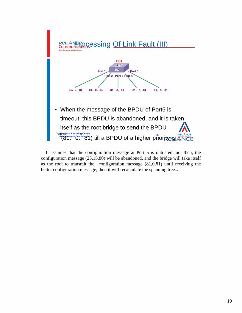
Processing Of Link Fault (III)
• When the message of the BPDU of Port5 is timeout, this BPDU is abandoned, and it is taken itself as the root bridge to send the BPDU
(81,0,81) till a BPDU of a higher priority is
Port 1Port 1Port 2Port 2 Port 3Port 3 Port 4Port 4
Port 5Port 5
8181,,00,,8181 8181,,00,,8181 8181,,00,,81 81 8181,,00,,81 81 8181,,00,,81 81
B81B81
It assumes that the configuration message at Port 5 is outdated too, then, the configuration message (23,15,80) will be abandoned, and the bridge will take itself as the root to transmit the configuration message (81,0,81) until receiving the better configuration message, then it will recalculate the spanning tree.。

20
Network Learning CentreProprietary & Confidential
2020Page 20
Temporary Loops Or Disconnection
• If the ports at the Forwarding status have not realized that they should stop forwarding, temporary loops might exist.
• If ports blocked have not realized that they should start forwarding, it might lead to temporary disconnection.
ROOTROOT
ROOTROOT
When the link failed and the network topology is changed, the new configuration message would be spread over the whole network always after a certain delay. Then, what will happen on other bridges before they discover the topology change?
One possibility may be that the ports in forwarding status in the old topology should be blocked in the new one, but it does not aware of that and results in the temporary path loop;
The other possibility may be that the blocked ports in the old topology should join the data transmission in the new topology, but if it does not know, it may cause the network to temporarily lose the connectivity.
It does not much matter with the second possibility; a few of packets will be lost at most. While the jeopardousness of the first possibility is already talked about a lot in the above, I guess that the readers might worry about it. It does not matter. The timer policy of spanning tree algorithm has provided a very good solution.

21
Network Learning CentreProprietary & Confidential
2121Page 21
How to avoid temporary loops?
• Forward Delay: Maximum delay for configuration message to be
broadcasted to the whole network
– Design interim status: ports at the interim status merely learns
address info of sites, but does not forward any data
– Ports enter the interim status from the blocked status after the
Forward Delay, then enter the Forwarding status after the Forward
Delay
• Ports will go through a certain delay to change from the blocking
status to the forwarding status. This time should at least be twice the
forward delay
When a blocked port needs to turn into the forwarding status, a certain delay is required. The delay is at least twice over the required time to ensure that the new configuration message is spread over the whole network. We can suppose the "forward delay" is the time to spread the configuration message over the whole network and we will design an intermediate status; and the port in the intermediate status can only study the address information of the site and can not take part in the data transmission. Through the "forward delay", the port will be turned from the blocked status into the intermediate status, and it will start to forward the data after the "forward delay" again.
22
Network Learning CentreProprietary & Confidential
2222Page 22
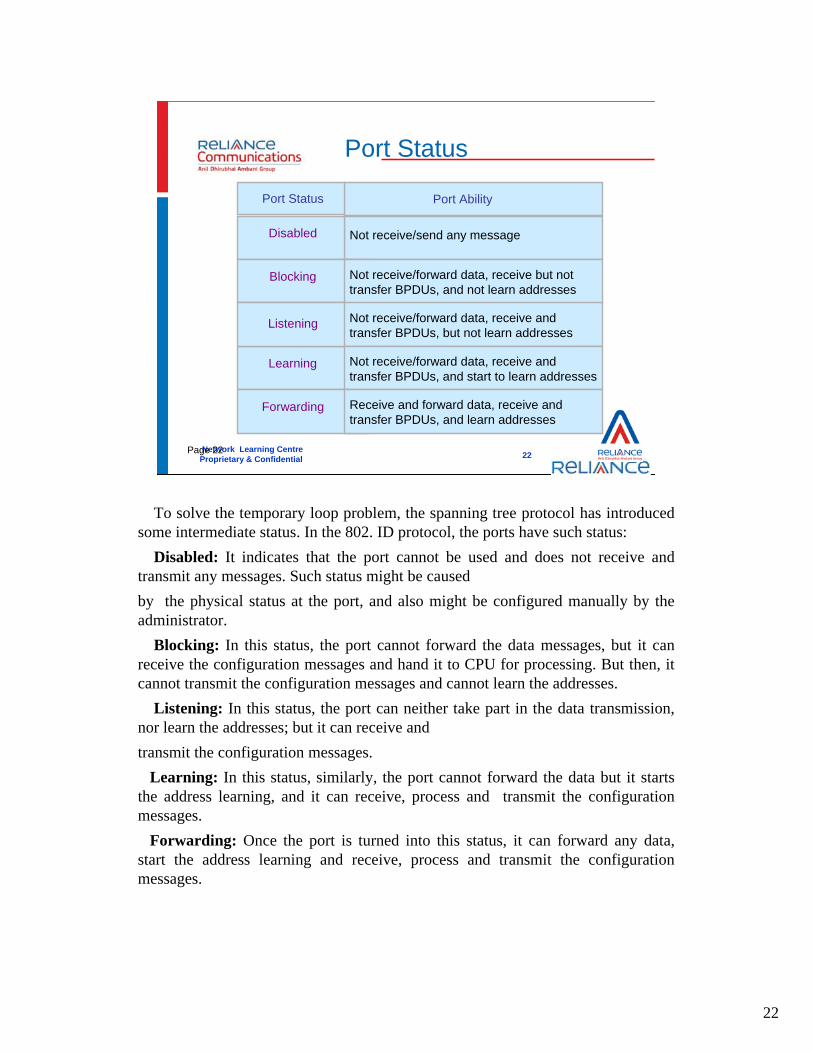
Port Status
Port Ability
Not receive/send any messageDisabled
Blocking
Listening
Learning
Port Status
Forwarding
Not receive/forward data, receive but not transfer BPDUs, and not learn addresses
Not receive/forward data, receive and transfer BPDUs, but not learn addresses
Not receive/forward data, receive and transfer BPDUs, and start to learn addresses
Receive and forward data, receive and transfer BPDUs, and learn addresses
To solve the temporary loop problem, the spanning tree protocol has introduced some intermediate status. In the 802. ID protocol, the ports have such status:
Disabled: It indicates that the port cannot be used and does not receive and transmit any messages. Such status might be caused by the physical status at the port, and also might be configured manually by the administrator.
Blocking: In this status, the port cannot forward the data messages, but it can receive the configuration messages and hand it to CPU for processing. But then, it cannot transmit the configuration messages and cannot learn the addresses.
Listening: In this status, the port can neither take part in the data transmission, nor learn the addresses; but it can receive and transmit the configuration messages.
Learning: In this status, similarly, the port cannot forward the data but it starts the address learning, and it can receive, process and transmit the configuration messages.
Forwarding: Once the port is turned into this status, it can forward any data, start the address learning and receive, process and transmit the configuration messages.

23
Network Learning CentreProprietary & Confidential
2323Page 23
Port Status Transition
DisabledDisabled
ListeningListening
BlockingBlocking
ForwardingForwarding
LearningLearning
11))interface enabledinterface enabled22))interfaceinterface disableddisabled33))interface is selected as root port or designated portinterface is selected as root port or designated port
44))interface is selected as backup interface ( blocking)interface is selected as backup interface ( blocking)55))Forward DelayForward Delay
((11)) ((22))
((11,,22))
((11,,22))
((11,,22))((11))
((22))((44))
((44)) ((55))
((44))((55))((33))
In the drawing, it presents the movement relationship of 5 states at the ports.We can see, when a port is selected as the root port or the designated port, it will
move from the blocking status to a interim status (the listening status); it goes through the delay of "forward delay" and moves to the next interim status (the learning status); and then, it goes through another delay of "forward delay" and moves to the forwarding status.
When a port is no longer as the root port or the designated port since the Topology changed, it will immediately move to the blocking status.
Besides, the port in any states can be turned into the disabled status.

24
Network Learning CentreProprietary & Confidential
2424Page 24
LAN ALAN A
Two Timers about the MAC Address Table
• There are two timers used to update the MAC address info:– A bigger timer is used when the topology is stable– A smaller timer is used when the topology changes
LAN BLAN B
LAN CLAN C
LAN ELAN E
LAN DLAN D
ROOTROOT
B1B1
B2B2
B3B3
B4B4
Topology structure change can enable shifts of the relative position of sites in the spanning tree, so that the MAC address info the network bridge originally learnt might be incorrect. So, the learnt MAC address info should also have an age, and if the address is not proven to be correct within this age, the address info is then discarded.
When the physical location of the site is changed, the learnt address information by the bridge might not be correct, so, every learnt address information has a lifetime; if no message confirms the address is correct in the lifetime, it will be abandoned. Everyone may image, if the physical location of the site is changed, e.g. pulling off a terminal equipment from an access port and plugging into another port will be certain to take a long time, then, the terminal will not transmit any message in the period; for the reason, its address information will be deleted from the address table of bridge. That is why the lifetime of address information can be a longer value in such condition.
But, when the topology of spanning tree is changed, the location of the site might be changed correspondingly, e.g. in the figure, the sites on the LANC are originally in the network segment where the Port 1 is located, as for the root bridge; latterly, the fault occurs on the LANA link and causes the spanning tree to recalculate and select a new route to the root bridge for the bridge B2; at the same time, the sites on the LANC are forwarded to the network segment where the Port 2 is located, as for the root bridge.
If the root bridge does not discover the change in a long period, the messages to the LANC will be forwarded from Port 1, but the real destination can not receive the messages. So how? The resolving measure that we adopt is to add up a shorter lifetime for each learnt address information. In the period that the bridge discovers the change of topology, the most possibility is the relevant location change of site; that is why the shorter lifetime is used to restrict the address items Here you might

25
Network Learning CentreProprietary & Confidential
2525Page 25
Transmission Of Topology Change Message
ROOTROOT
11
33
22
4444
55 55
Topology change notice messageTopology change notice messageTopology change response messageTopology change response messageTopology change messageTopology change message
But, another question appeared, not all bridges in the bridge network will discover the topology changing. For example, in the figure on the last page, the local change of B2 does not affect much other parts of network, and the bridges: B1, B3 and B4 might not be aware at all that the spanning tree is different; as to these bridges, the status of each port has not any changes and the links are normal; the only difference is the relative location of LANC, and yet, such a thing can only be discovered when the sites on LANC transmit the messages and before the transmission the bridges will wrongly forward the data to the LANC with the items of old address; so, it is necessary to make all the bridges in the network aware that the network topology has changed and the address transmission items might be abnormally! Must set the shorter message age for the learnt address items!
That is the purpose of the message of topology change in STP. There are three kinds of messages of topology change: the notification message of topology change, the response message of topology change and the message of topology change. The meanings of the three kinds of messages will be explained below:
1) The Notification message of topology change: the bridge, that discovers the topology change, periodically sends the notification message of topology change from the root port to the direction of Root Bridge in the cycle of "hello time"; and each non-root bridge, which receives the notification message, also plans to transmit the message toward the direction of Root Bridge. This message is in a special format, which has no data item and only makes the root aware of the topology change.
2) The response message of topology change: if the bridge that receives the notification message of topology change is not the root bridge, it needs to respond the response message of topology change; and the bridge that receives the response message will know: well, you have received my notification message and I should stop transmitting it This message is carried in the next configuration message

26
Network Learning CentreProprietary & Confidential
2626Page 26
Disadvantages of STP
• Recovery time is too long: two Forward Delay
• Network diameter should be less than 7.
Much about the STP has been introduced; however, it also has some shortcomings, which mainly involve two items:
1) The port needs double "forward delay" for changing from the blocked status into the forwarding status, resulting in the connectivity of network to be recovered after tens of seconds at least, and that is not profitable for services.
2) Only one example of spanning tree is applied for the whole bridge network. When the network is of a larger scale, it might require even longer convergent time, and the topology might change frequently.
To solve the first shortcoming, a "rapid spanning tree" algorithm is applied in the switch.

Network Learning CentreProprietary & Confidential
2727
Rapid Spanning Tree Protocol -RSTP

28
Network Learning CentreProprietary & Confidential
2828Page 28
Rapid Spanning Tree Protocol
• The RSTP evolved from the STP, and shares the same basic
concepts;
• RSTP has all functions of STP;
• RSTP can bring down the convergence time• Port Transition from Disable state to Learning state• New port type - Backup DP
The rapid spanning tree(RSTP) is developed on the basis of spanning tree algorithm, which inherits the basic concept of STP, i.e. it transmits the information of spanning tree also via the configuration message and performs the calculation by comparing the priority.
The rapid spanning tree can perform all the functions of spanning tree, and the difference is: under the precondition that the rapid spanning tree will not cause the temporary loop, it shortens the delay changing from the blocking status to the forwarding and resumes the connectivity of network as soon as possible to offer the much better services for users.

29
Network Learning CentreProprietary & Confidential
2929Page 29
STP vs. RSTP (Port States)
STP port state RSTP port state
Disabled Discarding
Blocking Discarding
Listening Discarding
Learning Learning
Forwarding Forwarding
But the ports states in STP are more than those in RSTP, in STP we have Disabled, Blocking, Listening, Learning, Forwarding; In RSTP only three states: Discarding, Learning, Forwarding.

30
Network Learning CentreProprietary & Confidential
3030Page 30
STP vs. RSTP (Port Types)
STP types of port RSTP types of port
Designated Port Designated Port
Root Port Root Port
Disabled Port Disabled Port
Alternate Port
Backup Port
In the STP ,we only have three kinds of ports: Designated Port, Root Port, Disabled Port, but in the RSTP we have five kinds of ports: Designated Port, Root Port, Disabled Port, Alternate Port, Backup Port. So you can see that RSTP have more kinds of ports than STP.

31
Network Learning CentreProprietary & Confidential
3131Page 31
Improvement Of Rapid Spanning Tree (I)
• A new root port can immediately enter the Forwarding status, if the original root port has entered the blocked status, and the designated
LAN ALAN A
TO ROOTTO ROOT
LAN ALAN A
LAN ALAN A LAN ALAN A
FF FF
FF
LAN ALAN A LAN ALAN A
FF FF
FF
TO ROOTTO ROOT
Designated PortDesignated Port
Root PortRoot PortBlocked PortBlocked Port Root PortRoot Port Blocked PortBlocked Port
Designated PortDesignated Port Designated PortDesignated Port Designated PortDesignated Port
From three aspects, the rapid spanning tree can realize the "Rapid" function:(1) A new root port changing from blocking status into forwarding status: if the
old root port is aware that itself is no longer as the root port and changes into the blocking status, while the designated port of network segment connected by the new root port is in the forwarding status, then, the new root port can change into the forwarding status without delay.
The condition shown in the figure is a typical example for the rapid status change of a root port.

32
Network Learning CentreProprietary & Confidential
3232Page 32
Improvement Of Rapid Spanning Tree (II)
• The designated port can make a handshake with the connected bridge so as to enter the Forwarding status quickly
LAN BLAN B
LAN ALAN A
FF11
2233
44 Handshake requestHandshake request
Handshake responseHandshake response
Designated PortDesignated Port
Root PortRoot Port
(2) A non-boundary designated port changing from the blocking status to the forwarding status: the "non-boundary" means that the port is connected with other bridges, not only be connected to the terminal equipment. The designated port waiting to change into the forwarding status transmits a message of handshake request to the downstream, if the bridge of downstream responds with an approving message, then, the designated port can turn into the forwarding status without delay.
The message of handshake request is in the next configuration message transmitted by the port and it is identified with a handshake flag bit; and the message of handshake response is also carried in the next configuration message transmitted by the port and identified with a hand approving flag bit.
The condition shown in figure is a typical example for the rapid status change of a non-boundary designated port.

33
Network Learning CentreProprietary & Confidential
3333Page 33
Attention
• Handshakes must occur on point to point links.
LAN ALAN A
LAN BLAN B LAN CLAN C
LAN ALAN A
FF
FF FF
Non Point to Point LinksNon Point to Point Links Handshake DiffusionHandshake Diffusion
Designated PortDesignated Port
Designated PortDesignated Port Designated PortDesignated Port
But, the rapid status change requires a precondition: a point-to-point link is required between the port initiating the handshake and the port responding the handshake! If the precondition cannot be satisfied, the handshake will not be responded. Then, the designated port has to wait for double "forward delay".
It is obvious that the point-to-point link has great influence on the performance of rapid spanning tree. Several conditions about the point-to-point link are listed as below:
The port is a aggregate port of links and it is bound with the aggregate links (please refers to the contents of port aggregation)
The port supports the function of self-negotiation and works in the full duplex mode via the negotiation (please refer to the relevant sections);
The administrator configures the port in full duplex modeIn other conditions, all the links connected by the port cannot be regarded as the
point-to-point links.Another point should be noted that the bridge responding to the handshake
would respond an approving message only after it changes its non-boundary designated port into the "blocking" status. Then, the non-boundary designated port of the bridge responding to the handshake also needs to initiate the handshake to the downstream. That is, the handshake will diffuse continuously till to the boundary of network, as shown in figure above.

34
Network Learning CentreProprietary & Confidential
3434Page 34
Improvement Of Rapid Spanning Tree (III)
• The edge ports, i.e., those directly connected to terminals but not to other bridges can directly enter the forwarding status, without any delay.
LAN BLAN B LAN CLAN C
LAN ALAN A
Edge PortEdge PortLAN DLAN DFF
TO ROOTTO ROOT
Blocked PortBlocked PortDesignated PortDesignated Port
(3) The boundary port changing from the blocking status to the forwarding status: it is easy to understand that the boundary ports are the ports directly connected with the terminal equipment and no longer connected to any other bridges. The statuses of these ports will not affect the connection of whole network or cause any loop. So, it can quickly turn into the forwarding status without delay.

Network Learning CentreProprietary & Confidential
3535
Faults of STP & RSTP
36
Network Learning CentreProprietary & Confidential
3636Page 36
Review STP & RSTP
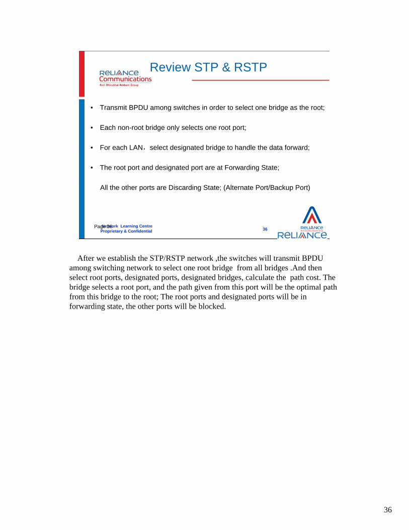
• Transmit BPDU among switches in order to select one bridge as the root;
• Each non-root bridge only selects one root port;
• For each LAN,select designated bridge to handle the data forward;
• The root port and designated port are at Forwarding State;
All the other ports are Discarding State; (Alternate Port/Backup Port)
After we establish the STP/RSTP network ,the switches will transmit BPDU among switching network to select one root bridge from all bridges .And then select root ports, designated ports, designated bridges, calculate the path cost. The bridge selects a root port, and the path given from this port will be the optimal path from this bridge to the root; The root ports and designated ports will be in forwarding state, the other ports will be blocked.

37
Network Learning CentreProprietary & Confidential
3737Page 37
VLAN load balance can not be implemented
VLAN 20 VLAN 10
Backup
Faults Of STP & RSTP
Link 1 Link 2
Between the two switches, we have two links, but the data from two VLANs can only use one link to transmit, only one link, the other one will be idle. So VLAN load balance can not be implemented.
In the figure above, we have configure VLAN 10 and VLAN 20,between the two switches ,we have two links :link1 and link 2, but link 2 is only backup;
But the data from VLAN 10 will go through link 1,and data from VLAN 20 will also go though link 1,so link 2 is always idle;In this situation, it can not realize VLAN load balance .

38
Network Learning CentreProprietary & Confidential
3838Page 38
Some specific VLAN messages can not reach the destination
10,20,30
10,30
20,30
10,20
10
203010,30
All the ports of VLAN 10 and 30 are discard state
Faults Of STP & RSTP
Switch A
In STP/RSTP, some links will be blocked for avoiding loop, only when some actual links are down ,the blocked links will be activated, so in this case, data from some VLANs can not get to the destination.
For example ,data from VLAN 10 and VLAN 30 can not get to the switch A, because the two links which can transmit VLAN 10 and VLAN 30 data are virtual links. Only when they become actual links, they can transmit data .

Network Learning CentreProprietary & Confidential
3939
Multiple Spanning Tree Protocol -MSTP

40
Network Learning CentreProprietary & Confidential
4040Page 40
What Is MSTP?
• MSTP : Multiple Spanning Tree Protocol
– Clause 13 of IEEE Std 802.1s, 2002 Edition
• MSTP is the perfect combination of VLAN load balance and
STP/RSTP.
• MSTP allows frames from different VLANs to follow separate paths,
each based on an independent Multiple Spanning Tree Instance
(MSTI)
Spanning tree protocol (STP) cannot enable Ethernet ports to transit their states rapidly. It costs two times of the forward delay for a port to transit to the forwarding state even if the port is in a point-to-point links or the port is an edge port.
Rapid spanning tree protocol (RSTP) enables Ethernet ports to transit their states rapidly, but it suffers from the same drawback as that of STP. That is, all bridges in a LAN with RSTP employed share one spanning tree and redundant links cannot be blocked by VLANs. In networks with RSTP employed, packets of all VLANs are forwarded along one spanning tree.
Multiple spanning tree protocol (MSTP) can disbranch a ring network to form a ring-free network with a tree topology. The network can prevent packets from being duplicated and forwarded endlessly. It provides multiple redundant paths for packet forwarding and balances the forwarding loads of different VLANs.
MSTP is compatible with both STP and RSTP. It overcomes the drawbacks that STP and RSTP suffer from. Since it enables spanning trees to be established rapidly and enables packets of different VLANs to be forwarded along the corresponding paths, it provides a better load-balancing mechanism for redundant links.

41
Network Learning CentreProprietary & Confidential
4141Page 41
MSTP Concepts
• Several terms of MSTP
– MSTP Multiple Spanning Tree Protocol
– MSTI Multiple Spanning Tree Instance
– MST Region Multiple Spanning Tree Region
– CIST Common and Internal Spanning Tree
– IST Internal Spanning Tree
– CST Common Spanning Tree
– SST Single Spanning Tree
There are some basic MSTP concepts. And in the follow slides ,we will introduce every concept particular.

42
Network Learning CentreProprietary & Confidential
4242Page 42
MSTP
• Each instance generates its own independent spanning tree
• The calculation of each instance is almost the same as RSTP
• Every instance can have different roots/topologies.
• The topology of each instance can be confirmed manually.
• The port within different instances can have different value of
spanning tree.
• The port within different instances can have different port roles/port
states.
There are some MSTP (multiple spanning tree protocol) principles. Each instance generates its own independent spanning tree, all the switches
configured the same VLAN can form a tree, we call the tree an instance . It means all the switches who have been configured the same VLAN belong to the same instance.
The calculation of each instance is almost the same as RSTP, Each instance sends its own BPDU to other bridges. Similar to STP and RSTP, MSTP uses BPDUs to figure out spanning trees too. In this case, the BPDUs carry MSTP configuration information of the switches.
To each instance ,it will choose a bridge as the root . Every instance can have different roots/topologies. The instance can communicate with other instances by the root. If we configure several VLANs on one switch ,then the switch maybe belong to several instances. And the port on it may have different value , different port roles and port states.

43
Network Learning CentreProprietary & Confidential
4343Page 43
MST Region
• MST Region:
– An MST Region comprises one or more MST Bridges with the
same MST Configuration Identifiers. These Regions and the
other Bridges are connected into a Common Spanning Tree
(CST).
– MCID: MST Configuration ID
• MCID contains the following components:
– Format Selector (1 Byte)
– Configuration Name (32 Bytes)
– Revision Level (2 Bytes)
– Configuration Digest (16 Bytes)
An MST (multiple spanning tree) region comprises of multiple switches and the corresponding network segments connected to these switches. These switches have MSTP employed. In order to be part of a same MST region, a group of switches must share the same configuration attributes.
Each MST Configuration Identifier contains the following components:1) A Configuration Identifier Format Selector: the value 0 encoded in a fixed
field of one octet to indicate the use of the following components as specified in this Standard.
2) The Configuration Name: a variable length text string encoded within a fixed field of 32 octets, conforming to RFC 2271’s definition of SnmpAdminString.
3) The Revision Level: an unsigned integer encoded within a fixed field of 2 octets.
4) The Configuration Digest: a 16 octet signature of type HMAC-MD5 (see IETF RFC 2104) created from the MST Configuration Table (3.26, 8.11). For the purposes of calculating the Configuration Digest, the MST Configuration Table is considered to contain 4096 consecutive two octet elements, where each element of the table (with the exception of the first and last) contains an MSTID value encoded as a binary number, with the first octet being most significant. The first element of the table contains the value 0, the second element the MSTID value corresponding to VID 1, the third element the MSTID value corresponding to VID 2, and so on, with the next to last element of the table containing the MSTID value corresponding to VID 4094, and the last element containing the value 0. The key used to generate the signature consists of the 16 octet string.

44
Network Learning CentreProprietary & Confidential
4444Page 44
MSTI
• MSTI: Multiple Spanning Tree Instance– Each instance can mapped to one or more
than one VLANs.– One VLAN can be mapped to one instance
only.– Multiple instances can be run on one switch.– All VLANs are mapped to instance 0 by
default if mapping relationship is not configured between VLAN and the instance.
A multiple spanning tree instance (MSTI) refers to spanning trees in a MST region.With MSTP employed, multiple spanning trees can be established in a MST region. These spanning trees are independent of each other. Each of these spanning trees corresponds to a VLAN.
Each instance can mapped to one or more than one VLANs. For example, we have configured VLAN 2 and VLAN 3; at the same time ,we have instance 2 and instance 3 in the region. Then we can both map the two VLANs to instance2 . Or map the VLAN2 to instance 2 and VLAN3 to instance 3. But remember one VLAN can be mapped to one instance only. it means if you have mapped VLAN 2 to instance 2 ,then you can not map VLAN 2 to instance at the same time.
Multiple instances can be run on one switch. For example ,if on a switch ,we have configured three VLANs, every VLAN is corresponds to an instance, then the switch can belong to three instances.

45
Network Learning CentreProprietary & Confidential
4545Page 45
Example
If we use STP/RSTP, some problems will occur
10,20,3010,20,30 10,2010,20
10,3010,30
10,3010,30
1010
3030 2020
20,3020,30
In the figure above, the five switches , we have configured VLAN 10 ,20,30, maybe different VLANs on different switches. If we run STP/RSTP, the data from VLANs maybe can not reach the destination or can not realize load balance.

46
Network Learning CentreProprietary & Confidential
4646Page 46
Example
2020 2020
2020
2020
10,20,3010,20,30 10,2010,20
10,3010,3010,3010,30
1010
3030 2020
20,3020,30
3030
30303030
3030
3030
1010 1010
1010
1010
1010
VLAN10 Root
VLAN20 Root
VLAN30 RootVLAN30 Root
VLAN20 Root
VLAN10 Root
SWITCH A
SWITCH B
SWITCH C
VLAN 10 is mapped to MSTI 1, Switch A is chose as the root bridge.VLAN 20 is mapped to MSTI 2, Switch B is chose as the root bridge.VLAN 30 is mapped to MSTI 3, Switch C is chose as the root bridge.The other VLAN are mapped to MSTI 0 (IST)The three instances compose one region .The MSTIs are simple RSTP instances that only exist inside a region.They run the RSTP automatically by default, without any extra configuration work.
47
Network Learning CentreProprietary & Confidential
4747Page 47
IST & CST
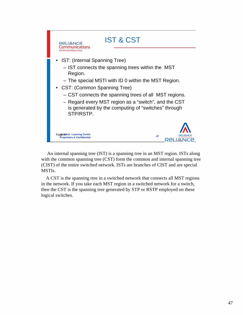
• IST: (Internal Spanning Tree)– IST connects the spanning trees within the MST
Region.– The special MSTI with ID 0 within the MST Region.
• CST: (Common Spanning Tree)– CST connects the spanning trees of all MST regions. – Regard every MST region as a “switch”, and the CST
is generated by the computing of “switches” through STP/RSTP.
An internal spanning tree (IST) is a spanning tree in an MST region. ISTs along with the common spanning tree (CST) form the common and internal spanning tree (CIST) of the entire switched network. ISTs are branches of CIST and are special MSTIs.
A CST is the spanning tree in a switched network that connects all MST regions in the network. If you take each MST region in a switched network for a switch, then the CST is the spanning tree generated by STP or RSTP employed on these logical switches.

48
Network Learning CentreProprietary & Confidential
4848Page 48
CIST & SST
• CIST: (Common and Internal Spanning Tree)– The IST and the CST, together make up a
CIST for the entire switching network. • SST: (Single Spanning Tree)
– In a region, there is only one switch. The single spanning tree may be supported by the STP or by the RSTP
A CIST is the spanning tree in a switched network that connects all switches in the network. It comprises the ISTs and the CST.
If in a region, we only has one switch, then we can call this tree single spanning tree.

49
Network Learning CentreProprietary & Confidential
4949Page 49
IST & CST (II)
CSTIST
CIST
Within a region ,we just use IST to connect all the switch together; among regions ,we use CST to connect all the regions together. So the IST and CST compose of the CIST.
within the region we should choose region root ,it is the root of the ISTs and the MSTIs of a MST region. The region root of a MST region differs with the topologies of the spanning trees in the region. So in the region ,if we have three instances, then we can have three region roots.
A common root bridge is the root of a CIST. So in the CIST above ,we have a common root .

50
Network Learning CentreProprietary & Confidential
5050Page 50
New Port Roles And Role Transformation (I)
• Common Root Bridge/CIST Root Bridge– The Common Root Bridge refers to the root
bridge of CIST. • Region Root
– The region root refers to the root of the IST and MSTI within MST region.
– Every instance has its own region root.
Common Root Bridge: It is the root bridge of CIST. according to BPDUs comparison, the whole network will choose a switch whose priority is the highest as the CIST root.
Region Root: It is the root of the IST and MSTI within MST region. Every instance has its own region root. So if there are three instances, then there are three region roots.

51
Network Learning CentreProprietary & Confidential
5151Page 51
New Port Roles And Role Transformation (I)
• Edge Port– The edge port is located at the MST
region edge, connecting different MST regions, MST region and STP region, or MST region and RSTP region.
• Master Port– Master port is the port connecting the
entire region to the Common Root Bridge .It has the shortest path cost to the common Root Bridge.
Edge Port: The edge port is located at the MST region edge, connecting different MST regions, MST region and STP region, or MST region and RSTP region.
Master Port: It is used to connect region to common root bridge. The path cost between master and common Root Bridge is the shortest. Master port is special Edge Port, its role on the IST/CIST is Root port, but master port on instances.

52
Network Learning CentreProprietary & Confidential
5252Page 52
New Port Roles And Role Transformation (II)
CIST Root
SST
Master Port
So you can see that in the for regions, we have four master ports, they are used to connect regions to common root bridge.
If the region wants to communicate with other regions ,they can use the master port.

53
Network Learning CentreProprietary & Confidential
5353Page 53
STP/RSTP Priority Vector Review
• STP/RSTP priority vectors are composed of the following components:– Root ID– Root Path Cost– Designated Bridge ID– Designated Port ID– Receiving Port ID.
STP/RSTP priority vectors are composed of the following components:Root ID: the Bridge Identifier of the Root Bridge .Root Path Cost: Path cost from the transmitting to Root Bridge .Designated Bridge ID: the bridge ID of the transmitting Bridge.Designated Port ID: the port ID of the Port through which the message was
transmitted.Receiving Port ID: the port ID of the Port through which the message was
received.

54
Network Learning CentreProprietary & Confidential
5454Page 54
CIST Priority Vector
• CIST priority vectors comprise the following components:– CIST Root ID– CIST External Root Path Cost– CIST Region Root ID– CIST Internal Root Path Cost– CIST Designated Bridge ID– CIST Designated Port ID– CIST Receiving Port ID
CIST Root ID: the Bridge Identifier of the CIST Root.CIST External Root Path Cost: the path cost between MST Regions from the transmitting
Bridge to the CIST Root.CIST Regional Root ID: the Bridge Identifier of the single bridge in a Region whose CIST
Root Port is a Boundary Port, or the Bridge Identifier of the CIST Root if that is within the Region.
CIST Regional Root ID: the Bridge Identifier of the single bridge in a Region whose CIST Root Port is a Boundary Port, or the Bridge Identifier of the CIST Root if that is within the Region.
CIST Internal Root Path Cost: the path cost to the CIST Regional Root.CIST Designated Bridge ID: the Bridge Identifier for the transmitting bridge for the CIST.CIST Designated Port ID: the Port Identifier for the transmitting port for the CIST.CIST Designated Port ID: the Port Identifier for the transmitting port for the CIST.CIST Receiving Port ID: not conveyed in Configuration Messages, used as tie-breaker
between otherwise equal priority vectors within a receiving Bridge.

55
Network Learning CentreProprietary & Confidential
5555Page 55
MSTI Priority Vector
• MSTI priority vectors is composed of the following components:– MSTI Regional Root ID– MSTI Internal Root Path Cost– MSTI Designated Bridge ID– MSTI Designated Port ID– MSTI Receiving Port ID
MSTI priority vector is composed of the following components:MSTI Regional Root ID: the Bridge Identifier of the MSTI Regional Root for
this particular MSTI in this MST Region.MSTI Internal Root Path Cost: the path cost to the MSTI Regional Root for
this particular MSTI in this MST Region.MSTI Designated Bridge ID: the Bridge Identifier for the transmitting bridge
for this MSTI.MSTI Designated Port ID: the Port Identifier for the transmitting port for this
MSTI.MSTI Receiving Port ID: not conveyed in Configuration Messages.

56
Network Learning CentreProprietary & Confidential
5656Page 56
Priority Vectors Calculation
• For all components, the lesser numerical value, the better it is; Earlier components in the above lists are more significant.
• As each Bridge Port receives priority vector information from Ports closer to the Root, additions are made to one or more priority vector components to yield a worse priority vector for potential transmission through other ports of the same Bridge.

57
Network Learning CentreProprietary & Confidential
5757Page 57
Understanding Priority Vectors Calculation
32768.032768.0--00--22 32768.032768.0--00--33
32768.032768.0--00--11 32768.032768.0--00--33
32768.032768.0--00--22 32768.032768.0--00--33
32768.032768.0--00--22
32768.032768.0--00--1132768.032768.0--00--11
32768.032768.0--00--11 32768.032768.0--00--33
32768.032768.0--00--22
Region 1
Region 1
We divide switch32768.0-0-2 and 32768.0-0-3 in the same region 1; then between region 1 and switch32768.0-0-1 ,we have two links ,so one should be blocked as the figure above.
If we divide switch32768.0-0-1 and 32768.0-0-3 in the same region 1; then between region 1 and switch32768.0-0-2 ,we have two links ,so one should be blocked as the figure above.

Network Learning CentreProprietary & Confidential
5858
PVST+ (Cisco)
• If one STP is used with redundant links but with multiple VLANs, several ports would be in blocking state
• PVST+ creates STP instance for each VLAN• Each STP instance can use different root switch• The traffic load is balanced among available link• Disadvantage- lot of messages & consume
processor time

Network Learning CentreProprietary & Confidential
5959
ThankYou