Embed Size (px)
Citation preview
2
M E M S H I E L D 2 M O U L D E D C A S E C
SPECIFICATION
■ One of the widest ranges in the world today
■ Built on the proven capability of Memshield 2
■ Full compliance with international standard
IEC 60947-2
■ MCCBs designed & manufactured in the U.K.
■ Extensive choice from 16-1600A
■ DIN - rail mounting
■ Compact dimensions
■ User fitted, front fitting accessories
■ Massive selection of accessories to adapt to
any application
■ Designed for use all around the world
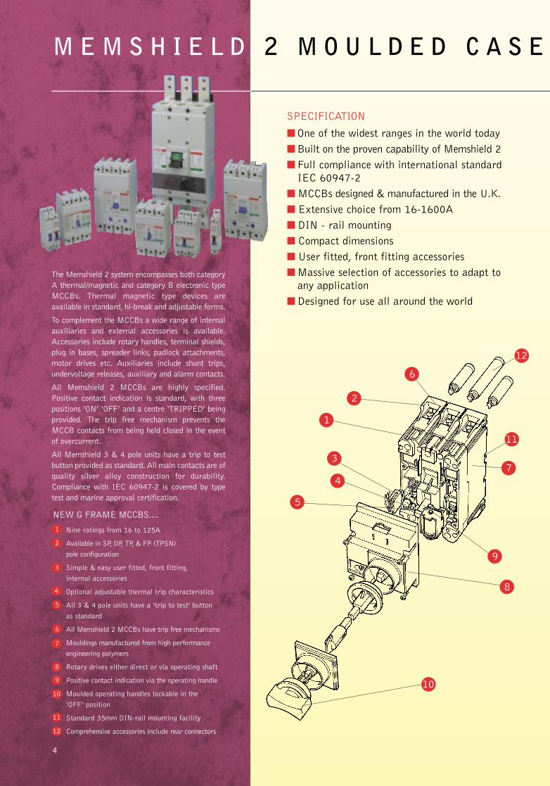
The Memshield 2 system encompasses both category
A thermal/magnetic and category B electronic type
MCCBs. Thermal magnetic type devices are
available in standard, hi-break and adjustable forms.
To complement the MCCBs a wide range of internal
auxiliaries and external accessories is available.
Accessories include rotary handles, terminal shields,
plug in bases, spreader links, padlock attachments,
motor drives etc. Auxiliaries include shunt trips,
undervoltage releases, auxiliary and alarm contacts.
All Memshield 2 MCCBs are highly specified.
Positive contact indication is standard, with three
positions ‘ON’ ‘OFF’ and a centre ‘TRIPPED’ being
provided. The trip free mechanism prevents the
MCCB contacts from being held closed in the event
of overcurrent.
All Memshield 3 & 4 pole units have a trip to test
button provided as standard. All main contacts are of
quality silver alloy construction for durability.
Compliance with IEC 60947-2 is covered by type
test and marine approval certification.
10
9
8
7
11
2
1
3
4
5
6
12
4
NEW G FRAME MCCBS....
Nine ratings from 16 to 125A
Available in SP, DP, TP, & FP (TPSN)
pole configuration
Simple & easy user fitted, front fitting,
internal accessories
Optional adjustable thermal trip characteristics
All 3 & 4 pole units have a ‘trip to test’ button
as standard
All Memshield 2 MCCBs have trip free mechanisms
Mouldings manufactured from high performance
engineering polymers
Rotary drives either direct or via operating shaft
Positive contact indication via the operating handle
Moulded operating handles lockable in the
‘OFF’ position
Standard 35mm DIN-rail mounting facility
Comprehensive accessories include rear connectors12
11
10
9
8
7
1
2
3
4
6
5
Memshield 2 P1-46 31/7/02 15:44 Page 7
3
E C I RC U I T B R E A K E R S - 1 6 T O 1 6 0 0 A
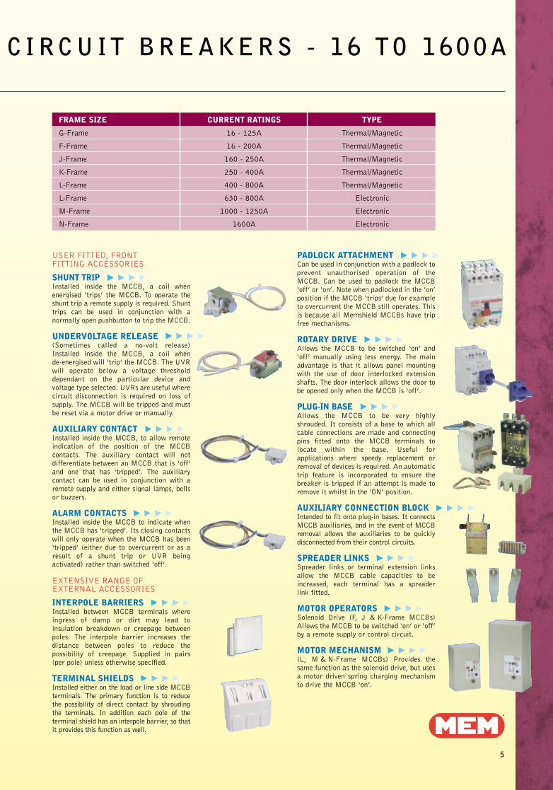
FRAME SIZE CURRENT RATINGS TYPE
G-Frame 16 - 125A Thermal/Magnetic
F-Frame 16 - 200A Thermal/Magnetic
J-Frame 160 - 250A Thermal/Magnetic
K-Frame 250 - 400A Thermal/Magnetic
L-Frame 400 - 800A Thermal/Magnetic
L-Frame 630 - 800A Electronic
M-Frame 1000 - 1250A Electronic
N-Frame 1600A Electronic
USER FITTED, FRONT FITTING ACCESSORIES
SHUNT TRIPInstalled inside the MCCB, a coil whenenergised ‘trips’ the MCCB. To operate theshunt trip a remote supply is required. Shunttrips can be used in conjunction with anormally open pushbutton to trip the MCCB.
UNDERVOLTAGE RELEASE(Sometimes called a no-volt release)Installed inside the MCCB, a coil when de-energised will ‘trip’ the MCCB. The UVRwill operate below a voltage thresholddependant on the particular device andvoltage type selected. UVRs are useful wherecircuit disconnection is required on loss ofsupply. The MCCB will be tripped and mustbe reset via a motor drive or manually.
AUXILIARY CONTACTInstalled inside the MCCB, to allow remoteindication of the position of the MCCBcontacts. The auxiliary contact will notdifferentiate between an MCCB that is ‘off’and one that has ‘tripped’. The auxiliarycontact can be used in conjunction with aremote supply and either signal lamps, bellsor buzzers.
ALARM CONTACTSInstalled inside the MCCB to indicate whenthe MCCB has ‘tripped’. Its closing contactswill only operate when the MCCB has been‘tripped’ (either due to overcurrent or as aresult of a shunt trip or UVR beingactivated) rather than switched ‘off’.
EXTENSIVE RANGE OF EXTERNAL ACCESSORIES
INTERPOLE BARRIERSInstalled between MCCB terminals whereingress of damp or dirt may lead toinsulation breakdown or creepage betweenpoles. The interpole barrier increases thedistance between poles to reduce thepossibility of creepage. Supplied in pairs(per pole) unless otherwise specified.
TERMINAL SHIELDSInstalled either on the load or line side MCCBterminals. The primary function is to reducethe possibility of direct contact by shroudingthe terminals. In addition each pole of theterminal shield has an interpole barrier, so thatit provides this function as well.
PADLOCK ATTACHMENTCan be used in conjunction with a padlock toprevent unauthorised operation of theMCCB. Can be used to padlock the MCCB‘off’ or ‘on’. Note when padlocked in the ‘on’position if the MCCB ‘trips’ due for exampleto overcurrent the MCCB still operates. Thisis because all Memshield MCCBs have tripfree mechanisms.
ROTARY DRIVEAllows the MCCB to be switched ‘on’ and‘off’ manually using less energy. The mainadvantage is that it allows panel mountingwith the use of door interlocked extensionshafts. The door interlock allows the door tobe opened only when the MCCB is ‘off’.
PLUG-IN BASEAllows the MCCB to be very highlyshrouded. It consists of a base to which allcable connections are made and connectingpins fitted onto the MCCB terminals tolocate within the base. Useful forapplications where speedy replacement orremoval of devices is required. An automatictrip feature is incorporated to ensure thebreaker is tripped if an attempt is made toremove it whilst in the ‘ON’ position.
AUXILIARY CONNECTION BLOCK Intended to fit onto plug-in bases. It connectsMCCB auxiliaries, and in the event of MCCBremoval allows the auxiliaries to be quicklydisconnected from their control circuits.
SPREADER LINKSSpreader links or terminal extension linksallow the MCCB cable capacities to beincreased, each terminal has a spreader link fitted.
MOTOR OPERATORSSolenoid Drive (F, J & K-Frame MCCBs)Allows the MCCB to be switched ‘on’ or ‘off’by a remote supply or control circuit.
MOTOR MECHANISM (L, M & N-Frame MCCBs) Provides thesame function as the solenoid drive, but usesa motor driven spring charging mechanismto drive the MCCB ‘on’.
5
Memshield 2 P1-46 31/7/02 15:46 Page 8
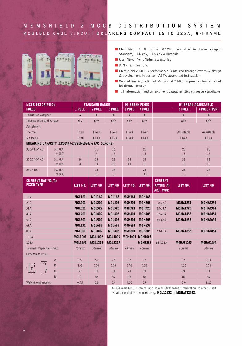
■ Memshield 2 G frame MCCBs available in three ranges:
Standard, Hi-break, Hi-break Adjustable
■ User fitted, front fitting accessories
■ DIN - rail mounting
■ Memshield 2 MCCB performance is assured through extensive design
& development in our own ASTA accredited test station
■ Current limiting action of Memshield 2 MCCBs provides low values of
let-through energy
■ Full information and time/current characteristics curves are available
M E M S H I E L D 2 M C C B D I S T R I B U T I O N S Y S T E MM O U L D E D C A S E C I R C U I T B R E A K E R S C O M P A C T 1 6 T O 1 2 5 A , G - F R A M E
2
MCCB DESCRIPTION STANDARD RANGE HI-BREAK FIXED HI-BREAK ADJUSTABLEPOLES 1 POLE 2 POLE 3 POLE 1 POLE 3 POLE 3 POLE 4 POLE (TPSN)
Utilisation category A A A A A A A
Impulse withstand voltage 8kV 8kV 8kV 8kV 8kV 8kV 8kV
Adjustment
Thermal Fixed Fixed Fixed Fixed Fixed Adjustable Adjustable
Magnetic Fixed Fixed Fixed Fixed Fixed Fixed Fixed
BREAKING CAPACITY IEC60947-2/BSEN60947-2 (AC 50/60HZ)
380/415V AC Icu (kA) 16 16 25 25 25
Ics (kA) 8 13 13 13 13
220/240V AC Icu (kA) 16 25 25 22 35 35 35
Ics (kA) 8 13 13 11 18 18 18
250V DC Icu (kA) 15 15 25 25 25
Ics (kA) 8 8 13 13 13
CURRENT RATING (A) CURRENTFIXED TYPE LIST NO. LIST NO. LIST NO. LIST NO. LIST NO. RATING (A) LIST NO. LIST NO.
ADJ. TYPE
16A MGL161 MGL162 MGL163 MGH161 MGH163
20A MGL201 MGL202 MGL203 MGH201 MGH203 18-25A MGHAT253 MGHAT254
32A MGL321 MGL322 MGL323 MGH321 MGH323 25-32A MGHAT323 MGHAT324
40A MGL401 MGL402 MGL403 MGH401 MGH403 32-45A MGHAT453 MGHAT454
50A MGL501 MGL502 MGL503 MGH501 MGH503 45-63A MGHAT633 MGHAT634
63A MGL631 MGL632 MGL633 MGH631 MGH633
80A MGL801 MGL802 MGL803 MGH801 MGH803 63-85A MGHAT853 MGHAT854
100A MGL1001 MGL1002 MGL1003 MGH1001 MGH1003
125A MGL1251 MGL1252 MGL1253 MGH1253 85-125A MGHAT1253 MGHAT1254
Terminal Capacities (max) 70mm2 70mm2 70mm2 70mm2 70mm2 70mm2 70mm2
Dimensions (mm)
A 25 50 75 25 75 75 100
B 138 138 138 138 138 138 138
C 71 71 71 71 71 71 71
D 87 87 87 87 87 87 87
Weight (kg) approx. 0.35 0.6 0.9 0.35 0.9 0.9 1.20
All G-Frame MCCBs can be supplied with 50ºC ambient calibration. To order, insert
‘X’ at the end of the list number eg. MGL1253X or MGHAT1253X.
6
Memshield 2 P1-46 31/7/02 15:46 Page 9
7
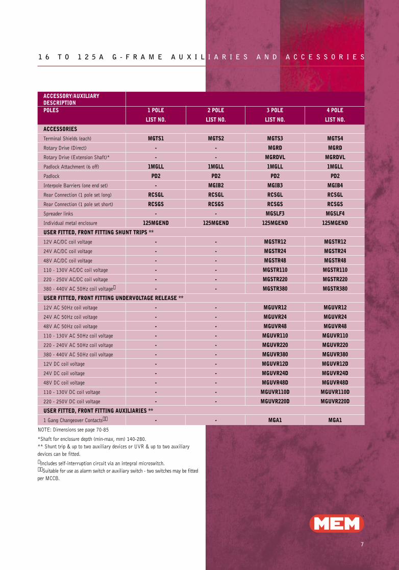
1 6 T O 1 2 5 A G - F R A M E A U X I L I A R I E S A N D A C C E S S O R I E S
ACCESSORY/AUXILIARYDESCRIPTIONPOLES 1 POLE 2 POLE 3 POLE 4 POLE
LIST NO. LIST NO. LIST NO. LIST NO.
ACCESSORIES
Terminal Shields (each) MGTS1 MGTS2 MGTS3 MGTS4
Rotary Drive (Direct) - - MGRD MGRD
Rotary Drive (Extension Shaft)* - - MGRDVL MGRDVL
Padlock Attachment (6 off) 1MGLL 1MGLL 1MGLL 1MGLL
Padlock PD2 PD2 PD2 PD2
Interpole Barriers (one end set) - MGIB2 MGIB3 MGIB4
Rear Connection (1 pole set long) RCSGL RCSGL RCSGL RCSGL
Rear Connection (1 pole set short) RCSGS RCSGS RCSGS RCSGS
Spreader links - - MGSLF3 MGSLF4
Individual metal enclosure 125MGEND 125MGEND 125MGEND 125MGEND
USER FITTED, FRONT FITTING SHUNT TRIPS **
12V AC/DC coil voltage - - MGSTR12 MGSTR12
24V AC/DC coil voltage - - MGSTR24 MGSTR24
48V AC/DC coil voltage - - MGSTR48 MGSTR48
110 - 130V AC/DC coil voltage - - MGSTR110 MGSTR110
220 - 250V AC/DC coil voltage - - MGSTR220 MGSTR220
380 - 440V AC 50Hz coil voltage✝ - - MGSTR380 MGSTR380
USER FITTED, FRONT FITTING UNDERVOLTAGE RELEASE **
12V AC 50Hz coil voltage - - MGUVR12 MGUVR12
24V AC 50Hz coil voltage - - MGUVR24 MGUVR24
48V AC 50Hz coil voltage - - MGUVR48 MGUVR48
110 - 130V AC 50Hz coil voltage - - MGUVR110 MGUVR110
220 - 240V AC 50Hz coil voltage - - MGUVR220 MGUVR220
380 - 440V AC 50Hz coil voltage - - MGUVR380 MGUVR380
12V DC coil voltage - - MGUVR12D MGUVR12D
24V DC coil voltage - - MGUVR24D MGUVR24D
48V DC coil voltage - - MGUVR48D MGUVR48D
110 - 130V DC coil voltage - - MGUVR110D MGUVR110D
220 - 250V DC coil voltage - - MGUVR220D MGUVR220D
USER FITTED, FRONT FITTING AUXILIARIES **
1 Gang Changeover Contacts✝✝ - - MGA1 MGA1
NOTE: Dimensions see page 70-85
*Shaft for enclosure depth (min-max, mm) 140-280.
** Shunt trip & up to two auxiliary devices or UVR & up to two auxiliary
devices can be fitted.
✝ Includes self-interruption circuit via an integral microswitch.✝✝ Suitable for use as alarm switch or auxiliary switch - two switches may be fitted
per MCCB.
Memshield 2 P1-46 31/7/02 15:46 Page 10
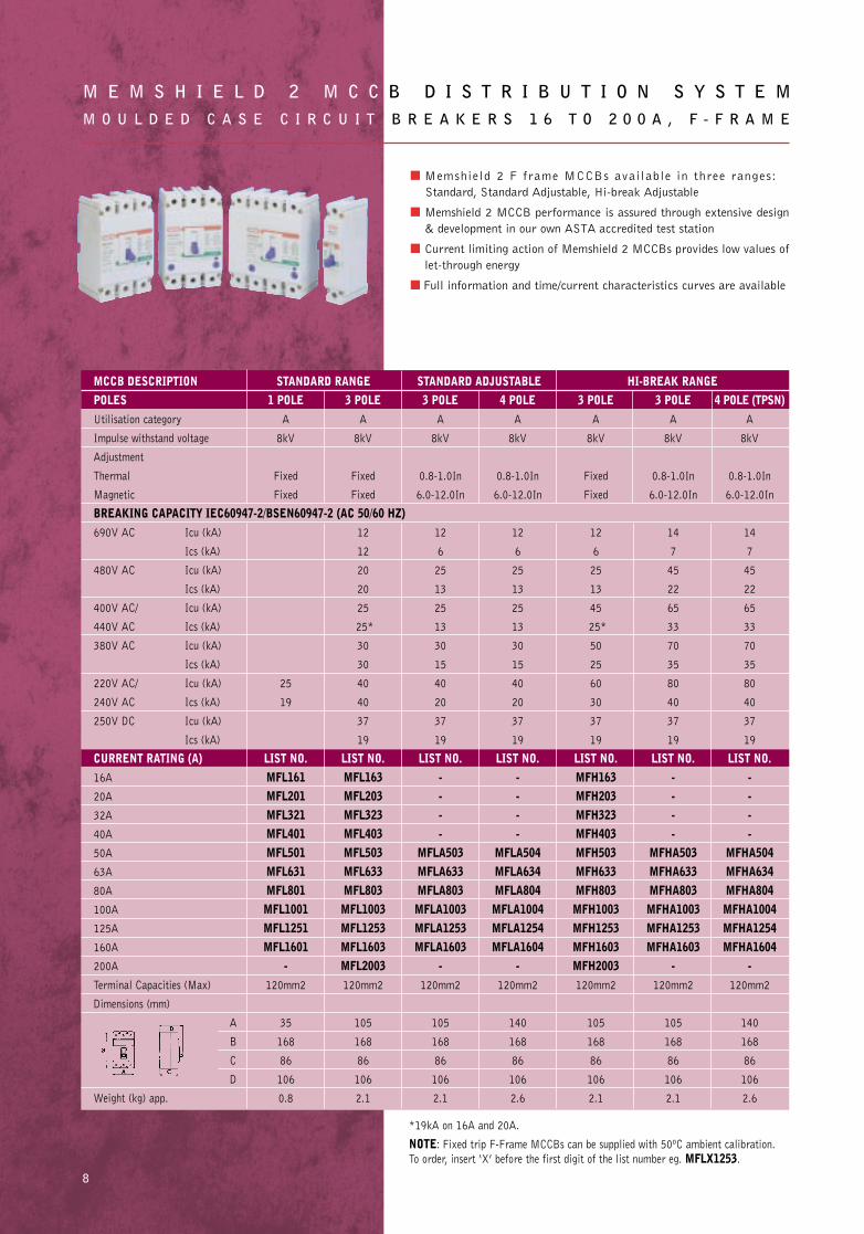
■ Memshield 2 F frame MCCBs available in three ranges:
Standard, Standard Adjustable, Hi-break Adjustable
■ Memshield 2 MCCB performance is assured through extensive design
& development in our own ASTA accredited test station
■ Current limiting action of Memshield 2 MCCBs provides low values of
let-through energy
■ Full information and time/current characteristics curves are available
M E M S H I E L D 2 M C C B D I S T R I B U T I O N S Y S T E MM O U L D E D C A S E C I R C U I T B R E A K E R S 1 6 T O 2 0 0 A , F - F R A M E
8
MCCB DESCRIPTION STANDARD RANGE STANDARD ADJUSTABLE HI-BREAK RANGEPOLES 1 POLE 3 POLE 3 POLE 4 POLE 3 POLE 3 POLE 4 POLE (TPSN)Utilisation category A A A A A A A
Impulse withstand voltage 8kV 8kV 8kV 8kV 8kV 8kV 8kV
Adjustment
Thermal Fixed Fixed 0.8-1.0In 0.8-1.0In Fixed 0.8-1.0In 0.8-1.0In
Magnetic Fixed Fixed 6.0-12.0In 6.0-12.0In Fixed 6.0-12.0In 6.0-12.0In
BREAKING CAPACITY IEC60947-2/BSEN60947-2 (AC 50/60 HZ)690V AC Icu (kA) 12 12 12 12 14 14
Ics (kA) 12 6 6 6 7 7
480V AC Icu (kA) 20 25 25 25 45 45
Ics (kA) 20 13 13 13 22 22
400V AC/ Icu (kA) 25 25 25 45 65 65
440V AC Ics (kA) 25* 13 13 25* 33 33
380V AC Icu (kA) 30 30 30 50 70 70
Ics (kA) 30 15 15 25 35 35
220V AC/ Icu (kA) 25 40 40 40 60 80 80
240V AC Ics (kA) 19 40 20 20 30 40 40
250V DC Icu (kA) 37 37 37 37 37 37
Ics (kA) 19 19 19 19 19 19
CURRENT RATING (A) LIST NO. LIST NO. LIST NO. LIST NO. LIST NO. LIST NO. LIST NO.16A MFL161 MFL163 - - MFH163 - -20A MFL201 MFL203 - - MFH203 - -32A MFL321 MFL323 - - MFH323 - -40A MFL401 MFL403 - - MFH403 - -50A MFL501 MFL503 MFLA503 MFLA504 MFH503 MFHA503 MFHA50463A MFL631 MFL633 MFLA633 MFLA634 MFH633 MFHA633 MFHA63480A MFL801 MFL803 MFLA803 MFLA804 MFH803 MFHA803 MFHA804100A MFL1001 MFL1003 MFLA1003 MFLA1004 MFH1003 MFHA1003 MFHA1004125A MFL1251 MFL1253 MFLA1253 MFLA1254 MFH1253 MFHA1253 MFHA1254160A MFL1601 MFL1603 MFLA1603 MFLA1604 MFH1603 MFHA1603 MFHA1604200A - MFL2003 - - MFH2003 - -Terminal Capacities (Max) 120mm2 120mm2 120mm2 120mm2 120mm2 120mm2 120mm2
Dimensions (mm)
A 35 105 105 140 105 105 140
B 168 168 168 168 168 168 168
C 86 86 86 86 86 86 86
D 106 106 106 106 106 106 106
Weight (kg) app. 0.8 2.1 2.1 2.6 2.1 2.1 2.6
*19kA on 16A and 20A.
NOTE: Fixed trip F-Frame MCCBs can be supplied with 50ºC ambient calibration.
To order, insert ‘X’ before the first digit of the list number eg. MFLX1253.
Memshield 2 P1-46 31/7/02 15:46 Page 11
9
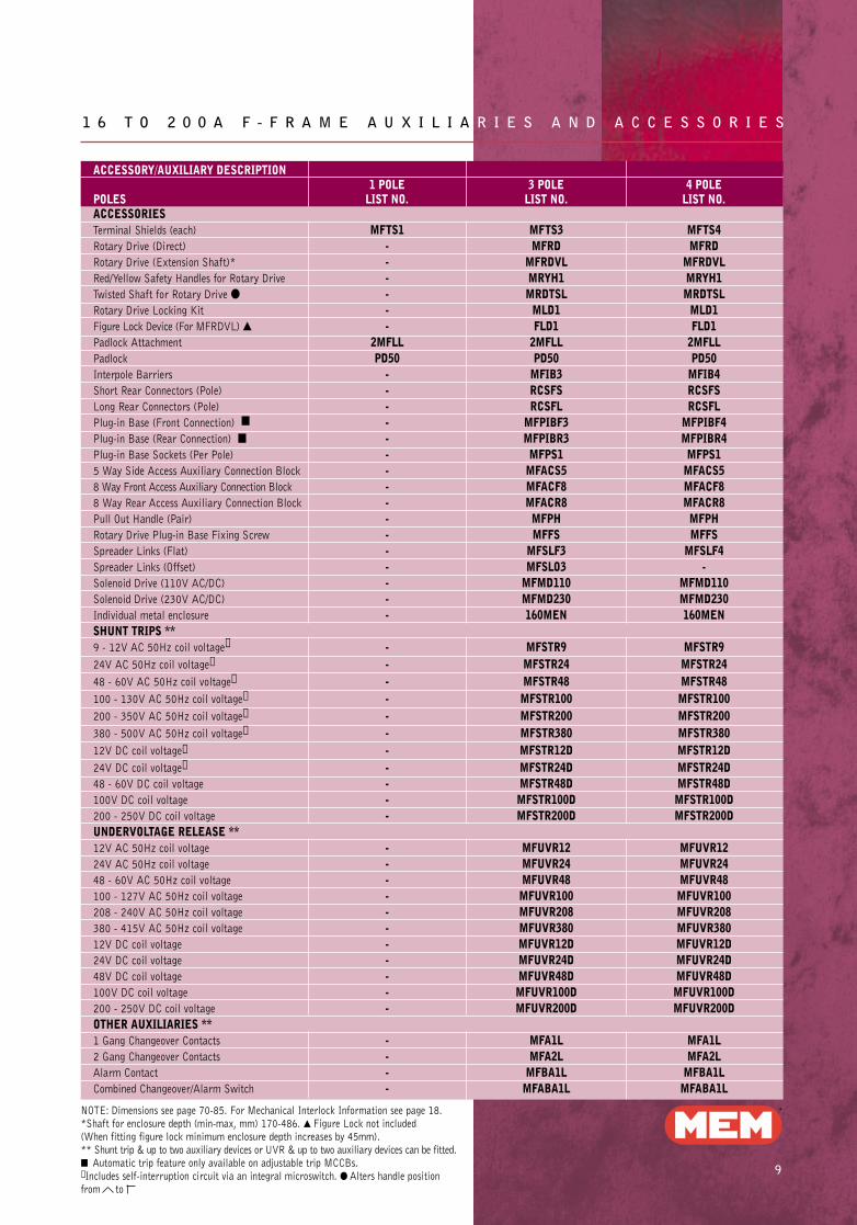
1 6 T O 2 0 0 A F - F R A M E A U X I L I A R I E S A N D A C C E S S O R I E S
ACCESSORY/AUXILIARY DESCRIPTION1 POLE 3 POLE 4 POLE
POLES LIST NO. LIST NO. LIST NO.ACCESSORIESTerminal Shields (each) MFTS1 MFTS3 MFTS4Rotary Drive (Direct) - MFRD MFRDRotary Drive (Extension Shaft)* - MFRDVL MFRDVLRed/Yellow Safety Handles for Rotary Drive - MRYH1 MRYH1Twisted Shaft for Rotary Drive ● - MRDTSL MRDTSLRotary Drive Locking Kit - MLD1 MLD1Figure Lock Device (For MFRDVL) ▲ - FLD1 FLD1Padlock Attachment 2MFLL 2MFLL 2MFLLPadlock PD50 PD50 PD50Interpole Barriers - MFIB3 MFIB4Short Rear Connectors (Pole) - RCSFS RCSFSLong Rear Connectors (Pole) - RCSFL RCSFLPlug-in Base (Front Connection) ■ - MFPIBF3 MFPIBF4Plug-in Base (Rear Connection) ■ - MFPIBR3 MFPIBR4Plug-in Base Sockets (Per Pole) - MFPS1 MFPS15 Way Side Access Auxiliary Connection Block - MFACS5 MFACS58 Way Front Access Auxiliary Connection Block - MFACF8 MFACF88 Way Rear Access Auxiliary Connection Block - MFACR8 MFACR8Pull Out Handle (Pair) - MFPH MFPHRotary Drive Plug-in Base Fixing Screw - MFFS MFFSSpreader Links (Flat) - MFSLF3 MFSLF4Spreader Links (Offset) - MFSLO3 -Solenoid Drive (110V AC/DC) - MFMD110 MFMD110Solenoid Drive (230V AC/DC) - MFMD230 MFMD230Individual metal enclosure - 160MEN 160MENSHUNT TRIPS **9 - 12V AC 50Hz coil voltage✝ - MFSTR9 MFSTR924V AC 50Hz coil voltage✝ - MFSTR24 MFSTR2448 - 60V AC 50Hz coil voltage✝ - MFSTR48 MFSTR48100 - 130V AC 50Hz coil voltage✝ - MFSTR100 MFSTR100200 - 350V AC 50Hz coil voltage✝ - MFSTR200 MFSTR200380 - 500V AC 50Hz coil voltage✝ - MFSTR380 MFSTR38012V DC coil voltage✝ - MFSTR12D MFSTR12D24V DC coil voltage✝ - MFSTR24D MFSTR24D48 - 60V DC coil voltage - MFSTR48D MFSTR48D100V DC coil voltage - MFSTR100D MFSTR100D200 - 250V DC coil voltage - MFSTR200D MFSTR200DUNDERVOLTAGE RELEASE **12V AC 50Hz coil voltage - MFUVR12 MFUVR1224V AC 50Hz coil voltage - MFUVR24 MFUVR2448 - 60V AC 50Hz coil voltage - MFUVR48 MFUVR48100 - 127V AC 50Hz coil voltage - MFUVR100 MFUVR100208 - 240V AC 50Hz coil voltage - MFUVR208 MFUVR208380 - 415V AC 50Hz coil voltage - MFUVR380 MFUVR38012V DC coil voltage - MFUVR12D MFUVR12D24V DC coil voltage - MFUVR24D MFUVR24D48V DC coil voltage - MFUVR48D MFUVR48D100V DC coil voltage - MFUVR100D MFUVR100D200 - 250V DC coil voltage - MFUVR200D MFUVR200DOTHER AUXILIARIES **1 Gang Changeover Contacts - MFA1L MFA1L2 Gang Changeover Contacts - MFA2L MFA2LAlarm Contact - MFBA1L MFBA1LCombined Changeover/Alarm Switch - MFABA1L MFABA1L
NOTE: Dimensions see page 70-85. For Mechanical Interlock Information see page 18.*Shaft for enclosure depth (min-max, mm) 170-486. ▲ Figure Lock not included (When fitting figure lock minimum enclosure depth increases by 45mm).** Shunt trip & up to two auxiliary devices or UVR & up to two auxiliary devices can be fitted.■ Automatic trip feature only available on adjustable trip MCCBs.✝ Includes self-interruption circuit via an integral microswitch. ● Alters handle position from to
Memshield 2 P1-46 31/7/02 15:47 Page 12
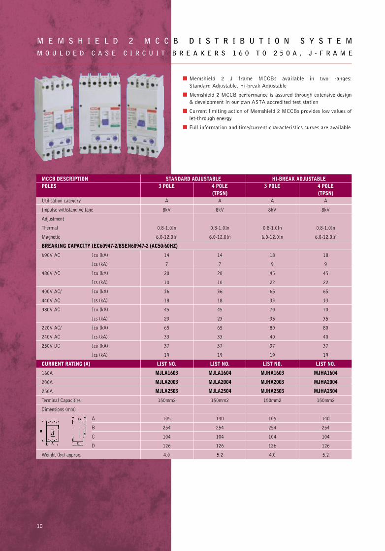
■ Memshield 2 J frame MCCBs available in two ranges:
Standard Adjustable, Hi-break Adjustable
■ Memshield 2 MCCB performance is assured through extensive design
& development in our own ASTA accredited test station
■ Current limiting action of Memshield 2 MCCBs provides low values of
let-through energy
■ Full information and time/current characteristics curves are available
M E M S H I E L D 2 M C C B D I S T R I B U T I O N S Y S T E MM O U L D E D C A S E C I R C U I T B R E A K E R S 1 6 0 T O 2 5 0 A , J - F R A M E
10
MCCB DESCRIPTION STANDARD ADJUSTABLE HI-BREAK ADJUSTABLEPOLES 3 POLE 4 POLE 3 POLE 4 POLE
(TPSN) (TPSN)Utilisation category A A A A
Impulse withstand voltage 8kV 8kV 8kV 8kV
Adjustment
Thermal 0.8-1.0In 0.8-1.0In 0.8-1.0In 0.8-1.0In
Magnetic 6.0-12.0In 6.0-12.0In 6.0-12.0In 6.0-12.0In
BREAKING CAPACITY IEC60947-2/BSEN60947-2 (AC50/60HZ)
690V AC Icu (kA) 14 14 18 18
Ics (kA) 7 7 9 9
480V AC Icu (kA) 20 20 45 45
Ics (kA) 10 10 22 22
400V AC/ Icu (kA) 36 36 65 65
440V AC Ics (kA) 18 18 33 33
380V AC Icu (kA) 45 45 70 70
Ics (kA) 23 23 35 35
220V AC/ Icu (kA) 65 65 80 80
240V AC Ics (kA) 33 33 40 40
250V DC Icu (kA) 37 37 37 37
Ics (kA) 19 19 19 19
CURRENT RATING (A) LIST NO. LIST NO. LIST NO. LIST NO.
160A MJLA1603 MJLA1604 MJHA1603 MJHA1604
200A MJLA2003 MJLA2004 MJHA2003 MJHA2004
250A MJLA2503 MJLA2504 MJHA2503 MJHA2504
Terminal Capacities 150mm2 150mm2 150mm2 150mm2
Dimensions (mm)
A 105 140 105 140
B 254 254 254 254
C 104 104 104 104
D 126 126 126 126
Weight (kg) approx. 4.0 5.2 4.0 5.2
Memshield 2 P1-46 31/7/02 15:47 Page 13
11
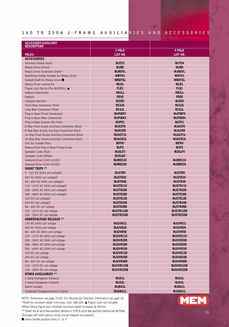
1 6 0 T O 2 5 0 A J - F R A M E A U X I L I A R I E S A N D A C C E S S O R I E S
ACCESSORY/AUXILIARY DESCRIPTION
3 POLE 4 POLEPOLES LIST NO. LIST NO. ACCESSORIESTerminal Shields (each) MJTS3 MJTS4Rotary Drive (Direct) MJRD MJRDRotary Drive (Extension Shaft)* MJRDVL MJRDVLRed/Yellow Safety Handles for Rotary Drive MRYH1 MRYH1Twisted Shaft for Rotary Drive ● MRDTSL MRDTSLRotary Drive Locking Kit MLD1 MLD1Figure Lock Device (For MJRDVL) ▲ FLD1 FLD1Padlock Attachment 3MJLL 3MJLLPadlock PD50 PD50Interpole Barriers MJIB3 MJIB4Short Rear Connectors (Pole) RCSJS RCSJSLong Rear Connectors (Pole) RCSJL RCSJLPlug-in Base (Front Connection) MJPIBF3 MJPIBF4Plug-in Base (Rear Connection) MJPIBR3 MJPIBR4Plug-in Base Sockets (Per Pole) MJPS1 MJPS18 Way Front Access Auxiliary Connection Block MJACF8 MJACF88 Way Rear Access Auxiliary Connection Block MJACR8 MJACR816 Way Front Access Auxiliary Connection Block MJACF16 MJACF1616 Way Rear Access Auxiliary Connection Block MJACR16 MJACR16Pull Out Handle (Pair) MFPH MFPHRotary Drive Plug-in Base Fixing Screw MJFS MJFSSpreader Links (Flat) MJSLF3 MJSLF4Spreader Links (Offset) MJSLO3 -Solenoid Drive (110V AC/DC) MJMD110 MJMD110Solenoid Drive (230V AC/DC) MJMD230 MJMD230SHUNT TRIPS **9 - 12V AC 50Hz coil voltage✝ MJSTR9 MJSTR924V AC 50Hz coil voltage✝ MJSTR24 MJSTR2448 - 60V AC 50Hz coil voltage✝ MJSTR48 MJSTR48110 - 127V AC 50Hz coil voltage✝ MJSTR110 MJSTR110208 - 240V AC 50Hz coil voltage✝ MJSTR208 MJSTR208380 - 480V AC 50Hz coil voltage✝ MJSTR380 MJSTR38012V DC coil voltage✝ MJSTR12D MJSTR12D24V DC coil voltage✝ MJSTR24D MJSTR24D48 - 60V DC coil voltage MJSTR48D MJSTR48D110 - 127V DC coil voltage MJSTR110D MJSTR110D220 - 250V DC coil voltage MJSTR220D MJSTR220DUNDERVOLTAGE RELEASE **12V AC 50Hz coil voltage MJUVR12 MJUVR1224V AC 50Hz coil voltage MJUVR24 MJUVR2448 - 60V AC 50Hz coil voltage MJUVR48 MJUVR48110 - 127V AC 50Hz coil voltage MJUVR110 MJUVR110208 - 240V AC 50Hz coil voltage MJUVR208 MJUVR208380 - 480V AC 50Hz coil voltage MJUVR380 MJUVR380550 - 600V AC 50Hz coil voltage MJUVR550 MJUVR55012V DC coil voltage MJUVR12D MJUVR12D24V DC coil voltage MJUVR24D MJUVR24D48 - 60V DC coil voltage MJUVR48D MJUVR48D110 - 127V DC coil voltage MJUVR110D MJUVR110D220 - 250V DC coil voltage MJUVR220D MJUVR220DOTHER AUXILIARIES **1 Gang Changeover Contacts MJA1L MJA1L2 Gang Changeover Contacts MJA2L MJA2LAlarm Contact MJBA1L MJBA1LCombined Changeover/Alarm Switch MJABA1L MJABA1L
NOTE: Dimensions see page 70-85. For Mechanical Interlock Information see page 18.
*Shaft for enclosure depth (min-max, mm) 188-504. ▲ Figure Lock not included
(When fitting figure lock minimum enclosure depth increases by 45mm).
** Shunt trip & up to two auxiliary devices or UVR & up to two auxiliary devices can be fitted.
✝ Includes self-interruption circuit via an integral microswitch.
● Alters handle position from to
Memshield 2 P1-46 31/7/02 15:47 Page 14
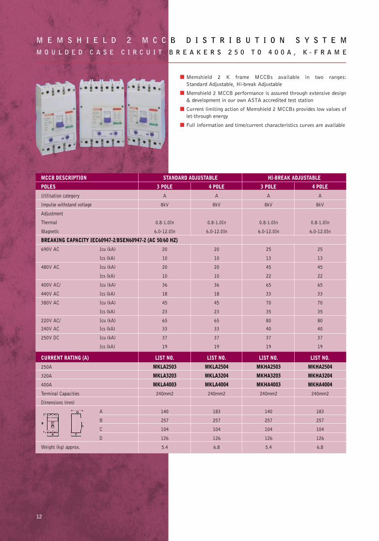
■ Memshield 2 K frame MCCBs available in two ranges:
Standard Adjustable, Hi-break Adjustable
■ Memshield 2 MCCB performance is assured through extensive design
& development in our own ASTA accredited test station
■ Current limiting action of Memshield 2 MCCBs provides low values of
let-through energy
■ Full information and time/current characteristics curves are available
M E M S H I E L D 2 M C C B D I S T R I B U T I O N S Y S T E MM O U L D E D C A S E C I R C U I T B R E A K E R S 2 5 0 T O 4 0 0 A , K - F R A M E
12
MCCB DESCRIPTION STANDARD ADJUSTABLE HI-BREAK ADJUSTABLE
POLES 3 POLE 4 POLE 3 POLE 4 POLE
Utilisation category A A A A
Impulse withstand voltage 8kV 8kV 8kV 8kV
Adjustment
Thermal 0.8-1.0In 0.8-1.0In 0.8-1.0In 0.8-1.0In
Magnetic 6.0-12.0In 6.0-12.0In 6.0-12.0In 6.0-12.0In
BREAKING CAPACITY IEC60947-2/BSEN60947-2 (AC 50/60 HZ)
690V AC Icu (kA) 20 20 25 25
Ics (kA) 10 10 13 13
480V AC Icu (kA) 20 20 45 45
Ics (kA) 10 10 22 22
400V AC/ Icu (kA) 36 36 65 65
440V AC Ics (kA) 18 18 33 33
380V AC Icu (kA) 45 45 70 70
Ics (kA) 23 23 35 35
220V AC/ Icu (kA) 65 65 80 80
240V AC Ics (kA) 33 33 40 40
250V DC Icu (kA) 37 37 37 37
Ics (kA) 19 19 19 19
CURRENT RATING (A) LIST NO. LIST NO. LIST NO. LIST NO.
250A MKLA2503 MKLA2504 MKHA2503 MKHA2504
320A MKLA3203 MKLA3204 MKHA3203 MKHA3204
400A MKLA4003 MKLA4004 MKHA4003 MKHA4004
Terminal Capacities 240mm2 240mm2 240mm2 240mm2
Dimensions (mm)
A 140 183 140 183
B 257 257 257 257
C 104 104 104 104
D 126 126 126 126
Weight (kg) approx. 5.4 6.8 5.4 6.8
Memshield 2 P1-46 31/7/02 15:48 Page 15
13
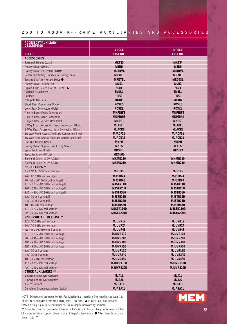
2 5 0 T O 4 0 0 A K - F R A M E A U X I L I A R I E S A N D A C C E S S O R I E S
ACCESSORY/AUXILIARY DESCRIPTION
3 POLE 4 POLEPOLES LIST NO. LIST NO.ACCESSORIESTerminal Shields (each) MKTS3 MKTS4Rotary Drive (Direct) MJRD MJRDRotary Drive (Extension Shaft)* MJRDVL MJRDVLRed/Yellow Safety Handles for Rotary Drive MRYH1 MRYH1Twisted Shaft for Rotary Drive ● MRDTSL MRDTSLRotary Drive Locking Kit MLD1 MLD1Figure Lock Device (For MJRDVL) ▲ FLD1 FLD1Padlock Attachment 3MJLL 3MJLLPadlock PD50 PD50Interpole Barriers MKIB3 MKIB4Short Rear Connectors (Pole) RCSKS RCSKSLong Rear Connectors (Pole) RCSKL RCSKLPlug-in Base (Front Connection) MKPIBF3 MKPIBF4Plug-in Base (Rear Connection) MKPIBR3 MKPIBR4Plug-in Base Sockets (Per Pole) MKPS1 MKPS18 Way Front Access Auxiliary Connection Block MJACF8 MJACF88 Way Rear Access Auxiliary Connection Block MJACR8 MJACR816 Way Front Access Auxiliary Connection Block MJACF16 MJACF1616 Way Rear Access Auxiliary Connection Block MJACR16 MJACR16Pull Out Handle (Pair) MKPH MKPHRotary Drive Plug-in Base Fixing Screw MKFS MKFSSpreader Links (Flat) MKSLF3 MKSLF4Spreader Links (Offset) MKSLO3 -Solenoid Drive (110V AC/DC) MKMD110 MKMD110Solenoid Drive (230V AC/DC) MKMD230 MKMD230SHUNT TRIPS **9 - 12V AC 50Hz coil voltage✝ MJSTR9 MJSTR924V AC 50Hz coil voltage✝ MJSTR24 MJSTR2448 - 60V AC 50Hz coil voltage✝ MJSTR48 MJSTR48110 - 127V AC 50Hz coil voltage✝ MJSTR110 MJSTR110208 - 240V AC 50Hz coil voltage✝ MJSTR208 MJSTR208380 - 480V AC 50Hz coil voltage✝ MJSTR380 MJSTR38012V DC coil voltage✝ MJSTR12D MJSTR12D24V DC coil voltage✝ MJSTR24D MJSTR24D48 -60V DC coil voltage MJSTR48D MJSTR48D110 - 127V DC coil voltage MJSTR110D MJSTR110D220 - 250V DC coil voltage MJSTR220D MJSTR220DUNDERVOLTAGE RELEASE **12V AC 50Hz coil voltage MJUVR12 MJUVR1224V AC 50Hz coil voltage MJUVR24 MJUVR2448 - 60V AC 50Hz coil voltage MJUVR48 MJUVR48110 - 127V AC 50Hz coil voltage MJUVR110 MJUVR110208 - 240V AC 50Hz coil voltage MJUVR208 MJUVR208380 - 480V AC 50Hz coil voltage MJUVR380 MJUVR380550 - 600V AC 50Hz coil voltage MJUVR550 MJUVR55012V DC coil voltage MJUVR12D MJUVR12D24V DC coil voltage MJUVR24D MJUVR24D48 - 60V DC coil voltage MJUVR48D MJUVR48D110 - 127V DC coil voltage MJUVR110D MJUVR110D220 - 250V DC coil voltage MJUVR220D MJUVR220DOTHER AUXILIARIES **1 Gang Changeover Contacts MJA1L MJA1L2 Gang Changeover Contacts MJA2L MJA2LAlarm Contact MJBA1L MJBA1LCombined Changeover/Alarm Switch MJABA1L MJABA1L
NOTE: Dimensions see page 70-85. For Mechanical Interlock Information see page 18.
*Shaft for enclosure depth (min-max, mm) 188-504. ▲ Figure Lock not included
(When fitting figure lock minimum enclosure depth increases by 45mm).
** Shunt trip & up to two auxiliary devices or UVR & up to two auxiliary devices can be fitted.
✝ Includes self-interruption circuit via an integral microswitch. ● Alters handle position
from to
Memshield 2 P1-46 31/7/02 15:49 Page 16
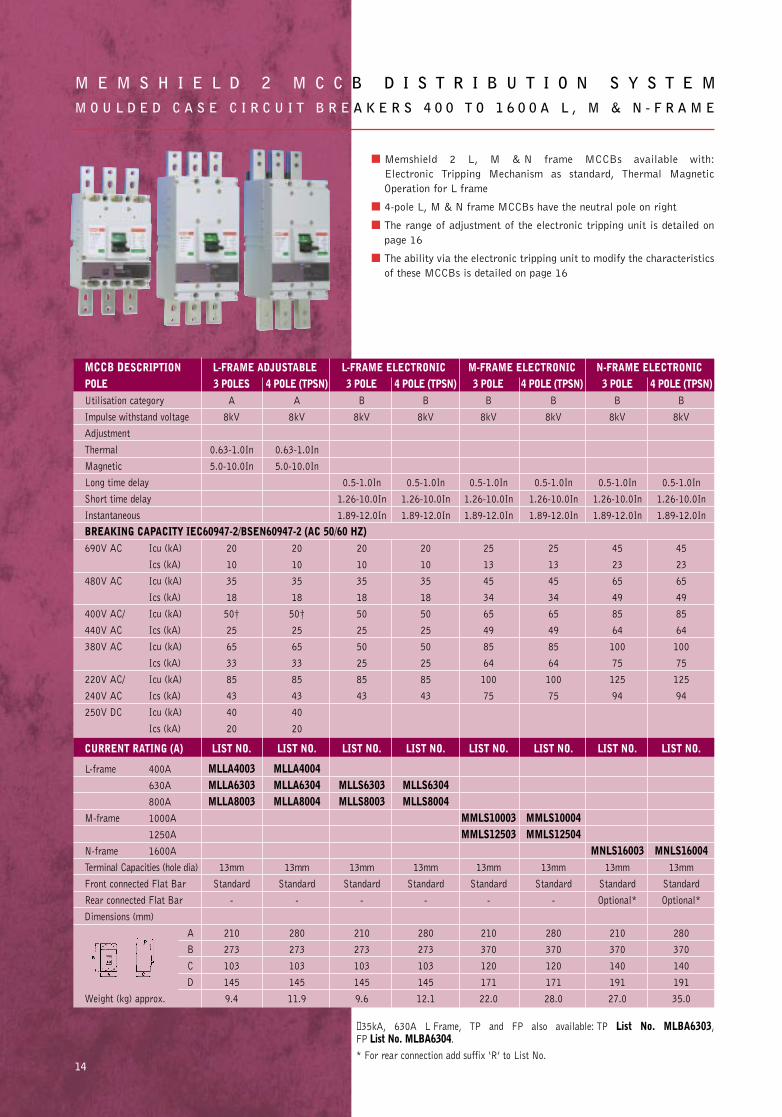
■ Memshield 2 L, M & N frame MCCBs available with:
Electronic Tripping Mechanism as standard, Thermal Magnetic
Operation for L frame
■ 4-pole L, M & N frame MCCBs have the neutral pole on right
■ The range of adjustment of the electronic tripping unit is detailed on
page 16
■ The ability via the electronic tripping unit to modify the characteristics
of these MCCBs is detailed on page 16
M E M S H I E L D 2 M C C B D I S T R I B U T I O N S Y S T E MM O U L D E D C A S E C I R C U I T B R E A K E R S 4 0 0 T O 1 6 0 0 A L , M & N - F R A M E
14
MCCB DESCRIPTION L-FRAME ADJUSTABLE L-FRAME ELECTRONIC M-FRAME ELECTRONIC N-FRAME ELECTRONICPOLE 3 POLES 4 POLE (TPSN) 3 POLE 4 POLE (TPSN) 3 POLE 4 POLE (TPSN) 3 POLE 4 POLE (TPSN)Utilisation category A A B B B B B B
Impulse withstand voltage 8kV 8kV 8kV 8kV 8kV 8kV 8kV 8kV
Adjustment
Thermal 0.63-1.0In 0.63-1.0In
Magnetic 5.0-10.0In 5.0-10.0In
Long time delay 0.5-1.0In 0.5-1.0In 0.5-1.0In 0.5-1.0In 0.5-1.0In 0.5-1.0In
Short time delay 1.26-10.0In 1.26-10.0In 1.26-10.0In 1.26-10.0In 1.26-10.0In 1.26-10.0In
Instantaneous 1.89-12.0In 1.89-12.0In 1.89-12.0In 1.89-12.0In 1.89-12.0In 1.89-12.0In
BREAKING CAPACITY IEC60947-2/BSEN60947-2 (AC 50/60 HZ)690V AC Icu (kA) 20 20 20 20 25 25 45 45
Ics (kA) 10 10 10 10 13 13 23 23
480V AC Icu (kA) 35 35 35 35 45 45 65 65
Ics (kA) 18 18 18 18 34 34 49 49
400V AC/ Icu (kA) 50† 50† 50 50 65 65 85 85
440V AC Ics (kA) 25 25 25 25 49 49 64 64
380V AC Icu (kA) 65 65 50 50 85 85 100 100
Ics (kA) 33 33 25 25 64 64 75 75
220V AC/ Icu (kA) 85 85 85 85 100 100 125 125
240V AC Ics (kA) 43 43 43 43 75 75 94 94
250V DC Icu (kA) 40 40
Ics (kA) 20 20
CURRENT RATING (A) LIST NO. LIST NO. LIST NO. LIST NO. LIST NO. LIST NO. LIST NO. LIST NO.
L-frame 400A MLLA4003 MLLA4004630A MLLA6303 MLLA6304 MLLS6303 MLLS6304800A MLLA8003 MLLA8004 MLLS8003 MLLS8004
M-frame 1000A MMLS10003 MMLS100041250A MMLS12503 MMLS12504
N-frame 1600A MNLS16003 MNLS16004Terminal Capacities (hole dia) 13mm 13mm 13mm 13mm 13mm 13mm 13mm 13mm
Front connected Flat Bar Standard Standard Standard Standard Standard Standard Standard Standard
Rear connected Flat Bar - - - - - - Optional* Optional*
Dimensions (mm)
A 210 280 210 280 210 280 210 280
B 273 273 273 273 370 370 370 370
C 103 103 103 103 120 120 140 140
D 145 145 145 145 171 171 191 191
Weight (kg) approx. 9.4 11.9 9.6 12.1 22.0 28.0 27.0 35.0
✝ 35kA, 630A L Frame, TP and FP also available: TP List No. MLBA6303, FP List No. MLBA6304.
* For rear connection add suffix ‘R’ to List No.
Memshield 2 P1-46 31/7/02 15:49 Page 17
15
4 0 0 T O 1 6 0 0 A L , M & N - F R A M E A U X I L I A R I E S A N D A C C E S S O R I E S
ACCESSORY/AUXILIARY L-FRAME M-FRAME N-FRAME
DESCRIPTION
POLES 3 POLE 4 POLE 3 POLE 4 POLE 3 POLE 4 POLE LIST NO. LIST NO. LIST NO. LIST NO. LIST NO. LIST NO.
ACCESSORIES
Terminal Shields (each) MLTS3 MLTS4 MMTS3 MMTS4 - -
Rotary Drive (Direct) MLRD MLRD MMRD MMRD MMRD MMRD
Rotary Drive (Extension Shaft)* MLRDVL MLRDVL MMRDVL MMRDVL MMRDVL MMRDVL
Red/Yellow Safety Handles
for Rotary DriveMRYH2 MRYH2 MRYH2 MRYH2 MRYH2 MRYH2
Twisted Shaft for Rotary Drive ● MRDTSL MRDTSL MRDTSL MRDTSL MRDTSL MRDTSL
Figure Lock Device
(For MLRDVL/MMRDVL) ▲FLD1 FLD3 FLD1 FLD3 FLD1 FLD3
Padlock Attachment 6MLLL 6MLLL 12MMLL 12MMLL 12MMLL 12MMLL
Padlock PD50 PD50 PD50 PD50 PD50 PD50
Interpole Barriers (Pole) MLIB3 MLIB4 MMIB3 MMIB4 MMIB3 MMIB4
Rear Connectors MLRCK3 MLRCK4 MMRCK3 MMRCK4 Factory fitted only
Extension Handle MXH1 MXH1 MXH1 MXH1 MXH1 MXH1
Motor Drive (110V AC Source) MLMD110 MLMD110 MMMD110 MMMD110 MMMD110 MMMD110
Motor Drive (240V AC Source) MLMD240 MLMD240 MMMD240 MMMD240 MMMD240 MMMD240
Motor Drive (24V DC Source) MLMD24D MLMD24D MMMD24D MMMD24D MMMD24D MMMD24D
Motor Drive (100V DC Source) MLMD100D MLMD100D MMMD100D MMMD100D MMMD100D MMMD100D
SHUNT TRIPS ** ■
100 - 115V AC 50Hz coil voltage✝ MLSTL100 MLSTL100 MMSTL100 MMSTL100 MMSTL100 MMSTL100
200 - 480V AC 50Hz coil voltage✝ MLSTL200 MLSTL200 MMSTL200 MMSTL200 MMSTL200 MMSTL200
24V DC coil voltage✝ MLSTL24D MLSTL24D MMSTL24D MMSTL24D MMSTL24D MMSTL24D
48V DC coil voltage✝ MLSTL48D MLSTL48D MMSTL48D MMSTL48D MMSTL48D MMSTL48D
100 - 115V DC coil voltage✝ MLSTL100D MLSTL100D MMSTL100D MMSTL100D MMSTL100D MMSTL100D
200 - 230V DC coil voltage✝ MLSTL200D MLSTL200D MMSTL200D MMSTL200D MMSTL200D MMSTL200D
UNDERVOLTAGE RELEASE ** ■
100 - 120V AC 50Hz coil voltage MLUVL100 MLUVL100 MMUVL100 MMUVL100 MMUVL100 MMUVL100
200 - 240V AC 50Hz coil voltage MLUVL200 MLUVL200 MMUVL200 MMUVL200 MMUVL200 MMUVL200
380 - 450V AC 50Hz coil voltage MLUVL380 MLUVL380 MMUVL380 MMUVL380 MMUVL380 MMUVL380
100 - 115V DC coil voltage MLUVL100D MLUVL100D MMUVL100D MMUVL100D MMUVL100D MMUVL100D
200 - 230V DC coil voltage MLUVL200D MLUVL200D MMUVL200D MMUVL200D MMUVL200D MMUVL200D
OTHER AUXILIARIES ** ■
1 Gang Changeover Contacts MLA1R MLA1R MMA1R3 MMA1R4 MMA1R3 MMA1R4
2 Gang Changeover Contacts MLA2R MLA2R MMA2R3 MMA2R4 MMA2R3 MMA2R4
3 Gang Changeover Contacts MLA3R MLA3R MMA3R3 MMA3R4 MMA3R3 MMA3R4
Alarm Contact MLBA1R MLBA1R MMBA1R3 MMBA1R4 MMBA1R3 MMBA1R4
Combined Changeover/Alarm Switch MLABA1R MLABA1R MMABA1R3 MMABA1R4 MMABA1R3 MMABA1R4
NOTE: Dimensions see page 70-85.
*Shaft for enclosure depth (Min-max, mm) L-Frame:- 160-474, M-Frame:- 185-500,
N-Frame:- 205-520. ▲ Figure Lock not included
(When fitting figure lock minimum enclosure depth increased by 45mm). ■ Must be factory
fitted or fitted by personnel who have attended an MEM approved installation course.
✝ Includes self-interruption circuit via an integral microswitch.
** Shunt trip & up to three auxiliary devices or UVR & up to three auxiliary devices can be fitted.
● Alters handle position from to
Memshield 2 P1-46 31/7/02 15:49 Page 18
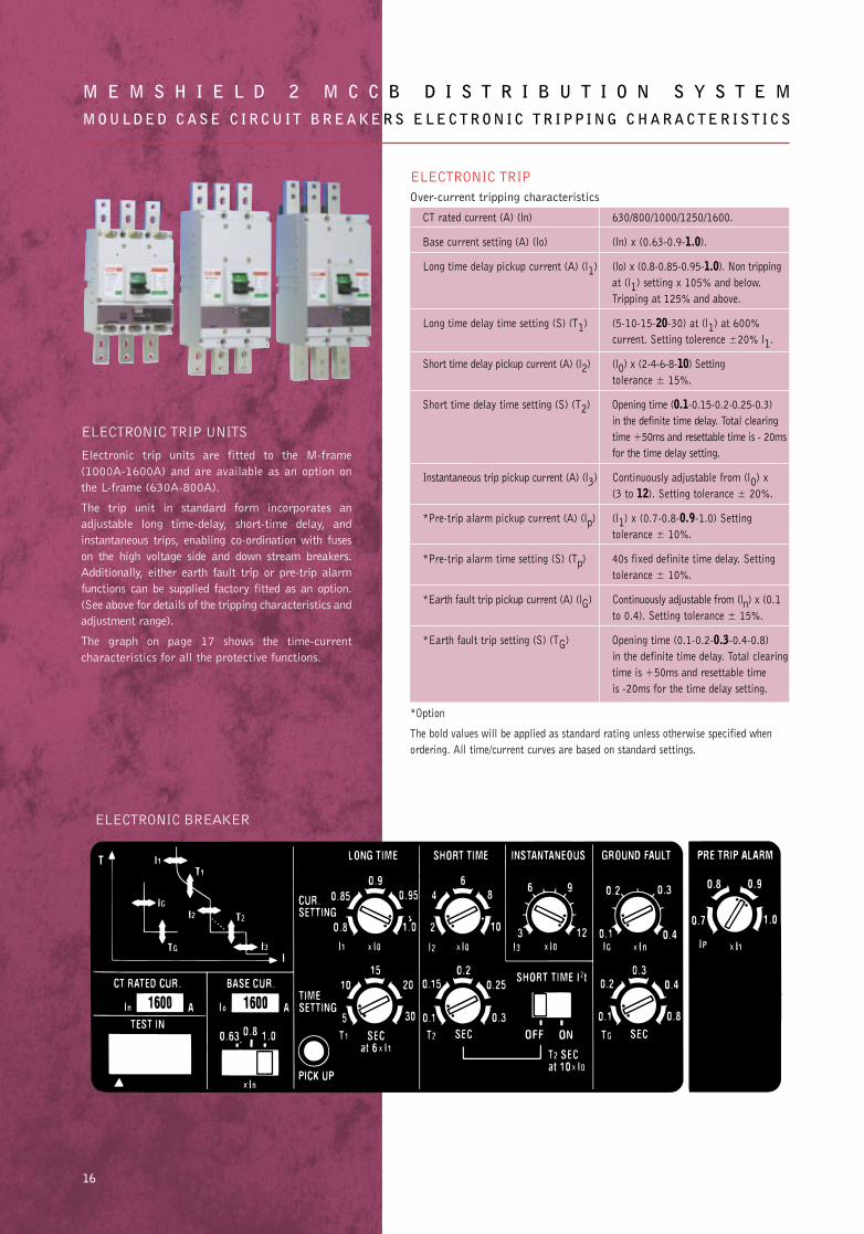
ELECTRONIC TRIP
Over-current tripping characteristics
CT rated current (A) (ln) 630/800/1000/1250/1600.
Base current setting (A) (lo) (ln) x (0.63-0.9-1.0).
Long time delay pickup current (A) (l1) (lo) x (0.8-0.85-0.95-1.0). Non tripping
at (l1) setting x 105% and below.
Tripping at 125% and above.
Long time delay time setting (S) (T1) (5-10-15-20-30) at (l1) at 600%
current. Setting tolerence ±20% l1.
Short time delay pickup current (A) (l2) (l0) x (2-4-6-8-10) Setting
tolerance ± 15%.
Short time delay time setting (S) (T2) Opening time (0.1-0.15-0.2-0.25-0.3)
in the definite time delay. Total clearing
time +50ms and resettable time is - 20ms
for the time delay setting.
Instantaneous trip pickup current (A) (l3) Continuously adjustable from (l0) x
(3 to 12). Setting tolerance ± 20%.
*Pre-trip alarm pickup current (A) (lp) (l1) x (0.7-0.8-0.9-1.0) Setting
tolerance ± 10%.
*Pre-trip alarm time setting (S) (Tp) 40s fixed definite time delay. Setting
tolerance ± 10%.
*Earth fault trip pickup current (A) (lG) Continuously adjustable from (ln) x (0.1
to 0.4). Setting tolerance ± 15%.
*Earth fault trip setting (S) (TG) Opening time (0.1-0.2-0.3-0.4-0.8)
in the definite time delay. Total clearing
time is +50ms and resettable time
is -20ms for the time delay setting.
*Option
The bold values will be applied as standard rating unless otherwise specified when
ordering. All time/current curves are based on standard settings.
M E M S H I E L D 2 M C C B D I S T R I B U T I O N S Y S T E MM O U L D E D C A S E C I R C U I T B R E A K E R S E L E C T R O N I C T R I P P I N G C H A R A C T E R I S T I C S
16
ELECTRONIC TRIP UNITS
Electronic trip units are fitted to the M-frame
(1000A-1600A) and are available as an option on
the L-frame (630A-800A).
The trip unit in standard form incorporates an
adjustable long time-delay, short-time delay, and
instantaneous trips, enabling co-ordination with fuses
on the high voltage side and down stream breakers.
Additionally, either earth fault trip or pre-trip alarm
functions can be supplied factory fitted as an option.
(See above for details of the tripping characteristics and
adjustment range).
The graph on page 17 shows the time-current
characteristics for all the protective functions.
ELECTRONIC BREAKER
Memshield 2 P1-46 31/7/02 15:49 Page 19
17
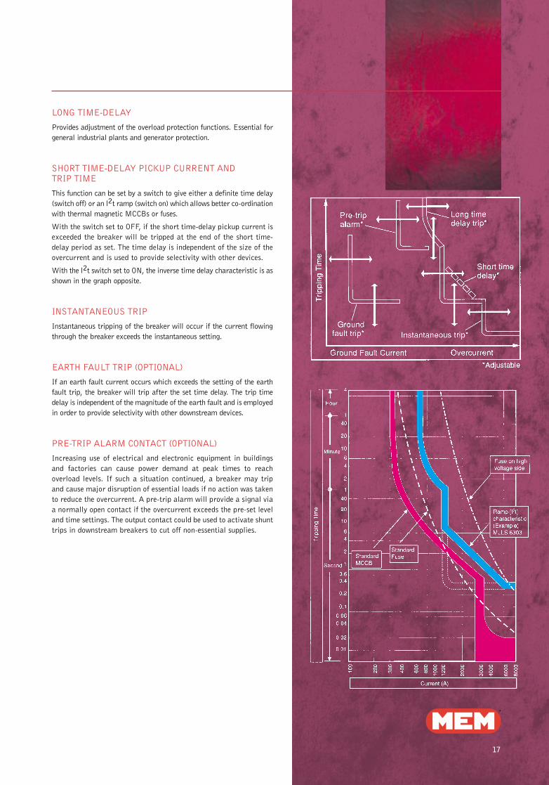
LONG TIME-DELAY
Provides adjustment of the overload protection functions. Essential for
general industrial plants and generator protection.
SHORT TIME-DELAY PICKUP CURRENT AND TRIP TIME
This function can be set by a switch to give either a definite time delay
(switch off) or an l2t ramp (switch on) which allows better co-ordination
with thermal magnetic MCCBs or fuses.
With the switch set to OFF, if the short time-delay pickup current is
exceeded the breaker will be tripped at the end of the short time-
delay period as set. The time delay is independent of the size of the
overcurrent and is used to provide selectivity with other devices.
With the l2t switch set to ON, the inverse time delay characteristic is as
shown in the graph opposite.
INSTANTANEOUS TRIP
Instantaneous tripping of the breaker will occur if the current flowing
through the breaker exceeds the instantaneous setting.
EARTH FAULT TRIP (OPTIONAL)
If an earth fault current occurs which exceeds the setting of the earth
fault trip, the breaker will trip after the set time delay. The trip time
delay is independent of the magnitude of the earth fault and is employed
in order to provide selectivity with other downstream devices.
PRE-TRIP ALARM CONTACT (OPTIONAL)
Increasing use of electrical and electronic equipment in buildings
and factories can cause power demand at peak times to reach
overload levels. If such a situation continued, a breaker may trip
and cause major disruption of essential loads if no action was taken
to reduce the overcurrent. A pre-trip alarm will provide a signal via
a normally open contact if the overcurrent exceeds the pre-set level
and time settings. The output contact could be used to activate shunt
trips in downstream breakers to cut off non-essential supplies.
Memshield 2 P1-46 31/7/02 15:50 Page 20
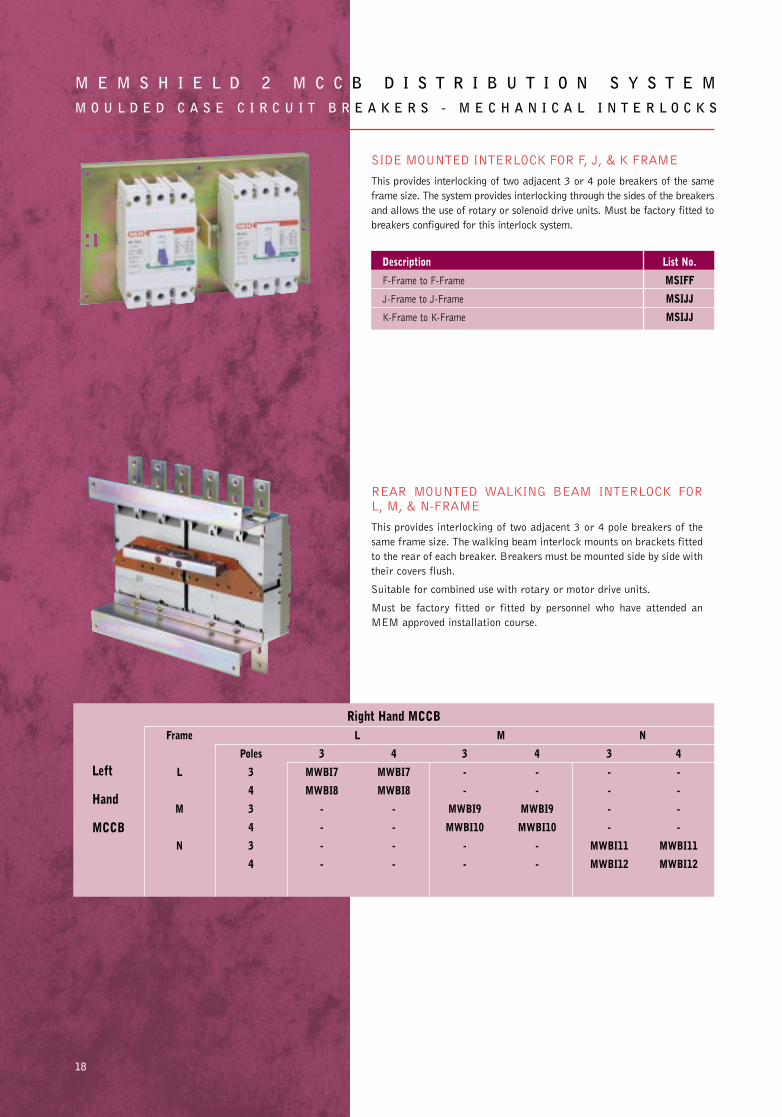
SIDE MOUNTED INTERLOCK FOR F, J, & K FRAME
This provides interlocking of two adjacent 3 or 4 pole breakers of the same
frame size. The system provides interlocking through the sides of the breakers
and allows the use of rotary or solenoid drive units. Must be factory fitted to
breakers configured for this interlock system.
M E M S H I E L D 2 M C C B D I S T R I B U T I O N S Y S T E MM O U L D E D C A S E C I R C U I T B R E A K E R S - M E C H A N I C A L I N T E R L O C K S
18
Description List No.
F-Frame to F-Frame MSIFF
J-Frame to J-Frame MSIJJ
K-Frame to K-Frame MSIJJ
REAR MOUNTED WALKING BEAM INTERLOCK FOR L, M, & N-FRAME
This provides interlocking of two adjacent 3 or 4 pole breakers of the
same frame size. The walking beam interlock mounts on brackets fitted
to the rear of each breaker. Breakers must be mounted side by side with
their covers flush.
Suitable for combined use with rotary or motor drive units.
Must be factory fitted or fitted by personnel who have attended an
MEM approved installation course.
Right Hand MCCBFrame L M N
Poles 3 4 3 4 3 4
L 3 MWBI7 MWBI7 - - - -
4 MWBI8 MWBI8 - - - -
M 3 - - MWBI9 MWBI9 - -
4 - - MWBI10 MWBI10 - -
N 3 - - - - MWBI11 MWBI11
4 - - - - MWBI12 MWBI12
Left
Hand
MCCB
Memshield 2 P1-46 31/7/02 15:50 Page 21
19
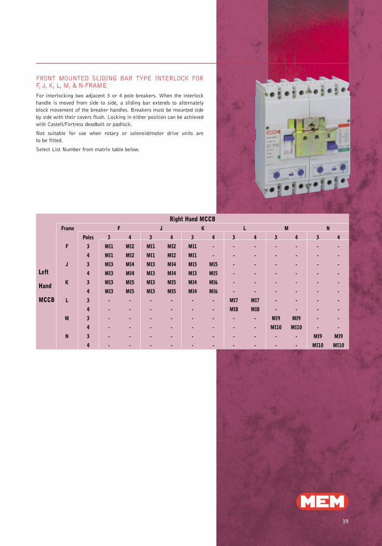
FRONT MOUNTED SLIDING BAR TYPE INTERLOCK FOR F, J, K, L, M, & N-FRAME
For interlocking two adjacent 3 or 4 pole breakers. When the interlock
handle is moved from side to side, a sliding bar extends to alternately
block movement of the breaker handles. Breakers must be mounted side
by side with their covers flush. Locking in either position can be achieved
with Castell/Fortress deadbolt or padlock.
Not suitable for use when rotary or solenoid/motor drive units are
to be fitted.
Select List Number from matrix table below.
Right Hand MCCBFrame F J K L M N
Poles 3 4 3 4 3 4 3 4 3 4 3 4
F 3 MI1 MI2 MI1 MI2 MI1 - - - - - - -
4 MI1 MI2 MI1 MI2 MI1 - - - - - - -
J 3 MI3 MI4 MI3 MI4 MI3 MI5 - - - - - -
4 MI3 MI4 MI3 MI4 MI3 MI5 - - - - - -
K 3 MI3 MI5 MI3 MI5 MI4 MI6 - - - - - -
4 MI3 MI5 MI3 MI5 MI4 MI6 - - - - - -
L 3 - - - - - - MI7 MI7 - - - -
4 - - - - - - MI8 MI8 - - - -
M 3 - - - - - - - - MI9 MI9 - -
4 - - - - - - - - MI10 MI10 - -
N 3 - - - - - - - - - - MI9 MI9
4 - - - - - - - - - - MI10 MI10
Left
Hand
MCCB
Memshield 2 P1-46 31/7/02 15:50 Page 22
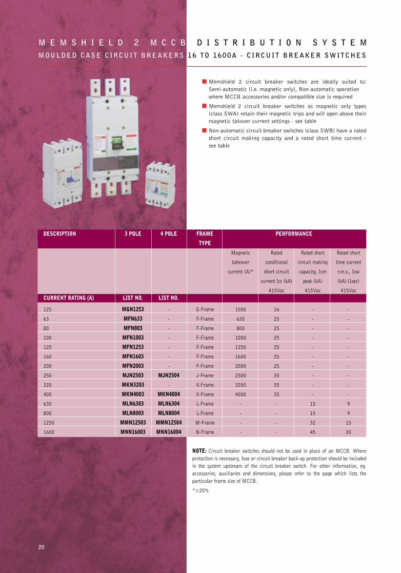
■ Memshield 2 circuit breaker switches are ideally suited to:
Semi-automatic (i.e. magnetic only), Non-automatic operation
where MCCB accessories and/or compatible size is required
■ Memshield 2 circuit breaker switches as magnetic only types
(class SWA) retain their magnetic trips and will open above their
magnetic takover current settings - see table
■ Non-automatic circuit breaker switches (class SWB) have a rated
short circuit making capacity and a rated short time current -
see table
M E M S H I E L D 2 M C C B D I S T R I B U T I O N S Y S T E MMOULDED CASE C IRCUIT BREAKERS 16 TO 1600A - C IRCUIT BREAKER SWITCHES
20
DESCRIPTION 3 POLE 4 POLE FRAME PERFORMANCE
TYPE
Magnetic Rated Rated short Rated short
takeover conditional circuit making time current
current (A)* short circuit capacity, Icm r.m.s., Icw
current Icc (kA) peak (kA) (kA) (1sec)
415Vac 415Vac 415Vac
CURRENT RATING (A) LIST NO. LIST NO.
125 MGN1253 - G-Frame 1000 16 - -
63 MFN633 - F-Frame 630 25 - -
80 MFN803 - F-Frame 800 25 - -
100 MFN1003 - F-Frame 1000 25 - -
125 MFN1253 - F-Frame 1250 25 - -
160 MFN1603 - F-Frame 1600 25 - -
200 MFN2003 - F-Frame 2000 25 - -
250 MJN2503 MJN2504 J-Frame 2500 35 - -
320 MKN3203 - K-Frame 3200 35 - -
400 MKN4003 MKN4004 K-Frame 4000 35 - -
630 MLN6303 MLN6304 L-Frame - - 15 9
800 MLN8003 MLN8004 L-Frame - - 15 9
1250 MMN12503 MMN12504 M-Frame - - 32 15
1600 MNN16003 MNN16004 N-Frame - - 45 20
NOTE: Circuit breaker switches should not be used in place of an MCCB. Where
protection is necessary, fuse or circuit breaker back-up protection should be included
in the system upstream of the circuit breaker switch. For other information, eg.
accessories, auxiliaries and dimensions, please refer to the page which lists the
particular frame size of MCCB.
*±20%
Memshield 2 P1-46 31/7/02 15:51 Page 23
21
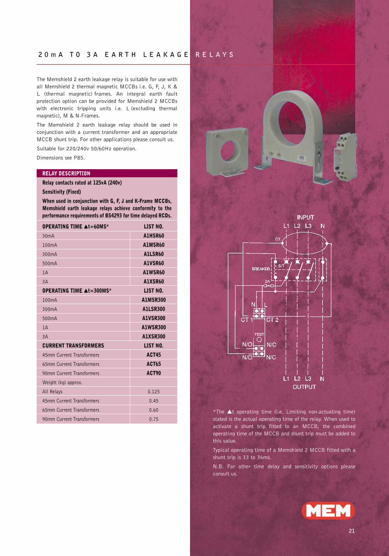
2 0 m A T O 3 A E A R T H L E A K A G E R E L A Y S
The Memshield 2 earth leakage relay is suitable for use with
all Memshield 2 thermal magnetic MCCBs i.e. G, F, J, K &
L (thermal magnetic) frames. An integral earth fault
protection option can be provided for Memshield 2 MCCBs
with electronic tripping units i.e. L (excluding thermal
magnetic), M & N-Frames.
The Memshield 2 earth leakage relay should be used in
conjunction with a current transformer and an appropriate
MCCB shunt trip. For other applications please consult us.
Suitable for 220/240v 50/60Hz operation.
Dimensions see P85.
*The ▲t operating time (i.e. Limiting non-actuating time)
stated is the actual operating time of the relay. When used to
activate a shunt trip fitted to an MCCB, the combined
operating time of the MCCB and shunt trip must be added to
this value.
Typical operating time of a Memshield 2 MCCB fitted with a
shunt trip is 33 to 36ms.
N.B. For other time delay and sensitivity options please
consult us.
RELAY DESCRIPTION
Relay contacts rated at 125vA (240v)
Sensitivity (Fixed)
When used in conjunction with G, F, J and K-Frame MCCBs,Memshield earth leakage relays achieve conformity to theperformance requirements of BS4293 for time delayed RCDs.
OPERATING TIME ▲t=60MS* LIST NO.
30mA A1HSR60
100mA A1MSR60
300mA A1LSR60
500mA A1VSR60
1A A1WSR60
3A A1XSR60
OPERATING TIME ▲t=300MS* LIST NO.
100mA A1MSR300
300mA A1LSR300
500mA A1VSR300
1A A1WSR300
3A A1XSR300
CURRENT TRANSFORMERS LIST NO.
45mm Current Transformers ACT45
65mm Current Transformers ACT65
90mm Current Transformers ACT90
Weight (kg) approx.
All Relays 0.125
45mm Current Transformers 0.45
65mm Current Transformers 0.60
90mm Current Transformers 0.75
Memshield 2 P1-46 31/7/02 15:51 Page 24
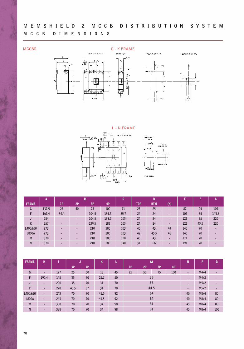
M E M S H I E L D 2 M C C B D I S T R I B U T I O N S Y S T E MM C C B D I M E N S I O N S
78
MCCBS
FRAMEGFJK
L400/630L800A
MN
A
137.5167.4254257273273370370
1P25
34.4------
2P50-------
3P75
104.5104.5139.5210210210210
4P100
139.5139.5183280280280280
C
7185.7103103103103120140
TOP2524242440424531
DBTM2524242443
45.54366
(N)----
4446--
E
87105126126145145171191
F
253535
43.570707070
G
109143.6220220
----
FRAME
G
F
J
K
L400/630
L800A
M
N
H
-
190.4
-
-
-
-
-
-
I
127
145
220
220
243
243
338
338
3P
25
35
35
43.5
70
70
70
70
4P
50
70
70
87
70
70
70
70
K
13
25.7
31
31
41.5
41.5
34
34
L
45
50
70
70
92
92
98
98
1P
25
2P
50
3P
75
4P
100
N
-
-
-
-
40
40
45
45
P
M4x4
M4x2
M5x2
M5x2
M8x4
M8x4
M8x4
M8x4
Q
-
-
-
-
80
80
80
100
G - K FRAME
L - N FRAME
B
J M
36
36
44.5
64
64
81
81
Memshield 2 P47-91 31/7/02 16:16 Page 35
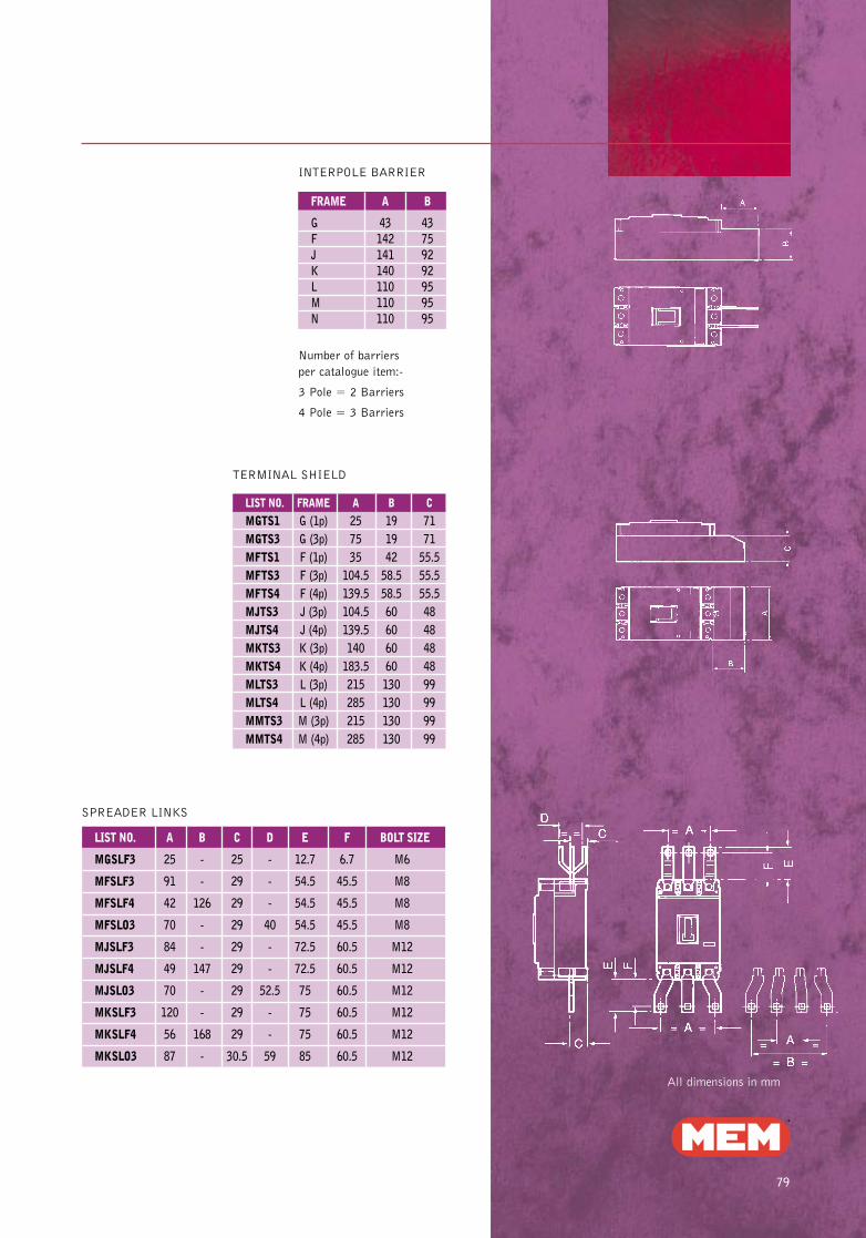
79
TERMINAL SHIELD
INTERPOLE BARRIER
FRAME A B
G 43 43F 142 75J 141 92K 140 92L 110 95M 110 95N 110 95
Number of barriers
per catalogue item:-
3 Pole = 2 Barriers
4 Pole = 3 Barriers
LIST NO. FRAME A B C
MGTS1 G (1p) 25 19 71MGTS3 G (3p) 75 19 71MFTS1 F (1p) 35 42 55.5MFTS3 F (3p) 104.5 58.5 55.5MFTS4 F (4p) 139.5 58.5 55.5MJTS3 J (3p) 104.5 60 48MJTS4 J (4p) 139.5 60 48MKTS3 K (3p) 140 60 48MKTS4 K (4p) 183.5 60 48MLTS3 L (3p) 215 130 99MLTS4 L (4p) 285 130 99MMTS3 M (3p) 215 130 99MMTS4 M (4p) 285 130 99
All dimensions in mm
LIST NO. A B C D E F BOLT SIZE
MGSLF3 25 - 25 - 12.7 6.7 M6
MFSLF3 91 - 29 - 54.5 45.5 M8
MFSLF4 42 126 29 - 54.5 45.5 M8
MFSLO3 70 - 29 40 54.5 45.5 M8
MJSLF3 84 - 29 - 72.5 60.5 M12
MJSLF4 49 147 29 - 72.5 60.5 M12
MJSLO3 70 - 29 52.5 75 60.5 M12
MKSLF3 120 - 29 - 75 60.5 M12
MKSLF4 56 168 29 - 75 60.5 M12
MKSLO3 87 - 30.5 59 85 60.5 M12
SPREADER LINKS
Memshield 2 P47-91 31/7/02 16:16 Page 36
M E M S H I E L D 2 M C C B D I S T R I B U T I O N S Y S T E MM C C B D I M E N S I O N S
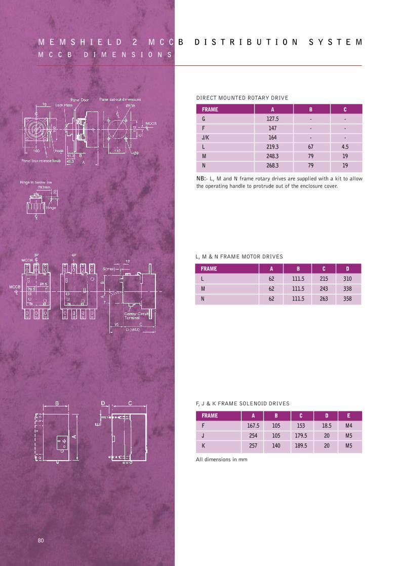
80
NB:- L, M and N frame rotary drives are supplied with a kit to allow
the operating handle to protrude out of the enclosure cover.
FRAME A B C D E
F 167.5 105 153 18.5 M4
J 254 105 179.5 20 M5
K 257 140 189.5 20 M5
FRAME A B C
G 127.5 - -
F 147 - -
J/K 164 - -
L 219.3 67 4.5
M 248.3 79 19
N 268.3 79 19
FRAME A B C D
L 62 111.5 215 310
M 62 111.5 243 338
N 62 111.5 263 358
DIRECT MOUNTED ROTARY DRIVE
F, J & K FRAME SOLENOID DRIVES
L, M & N FRAME MOTOR DRIVES
All dimensions in mm
Memshield 2 P47-91 31/7/02 16:16 Page 37
81
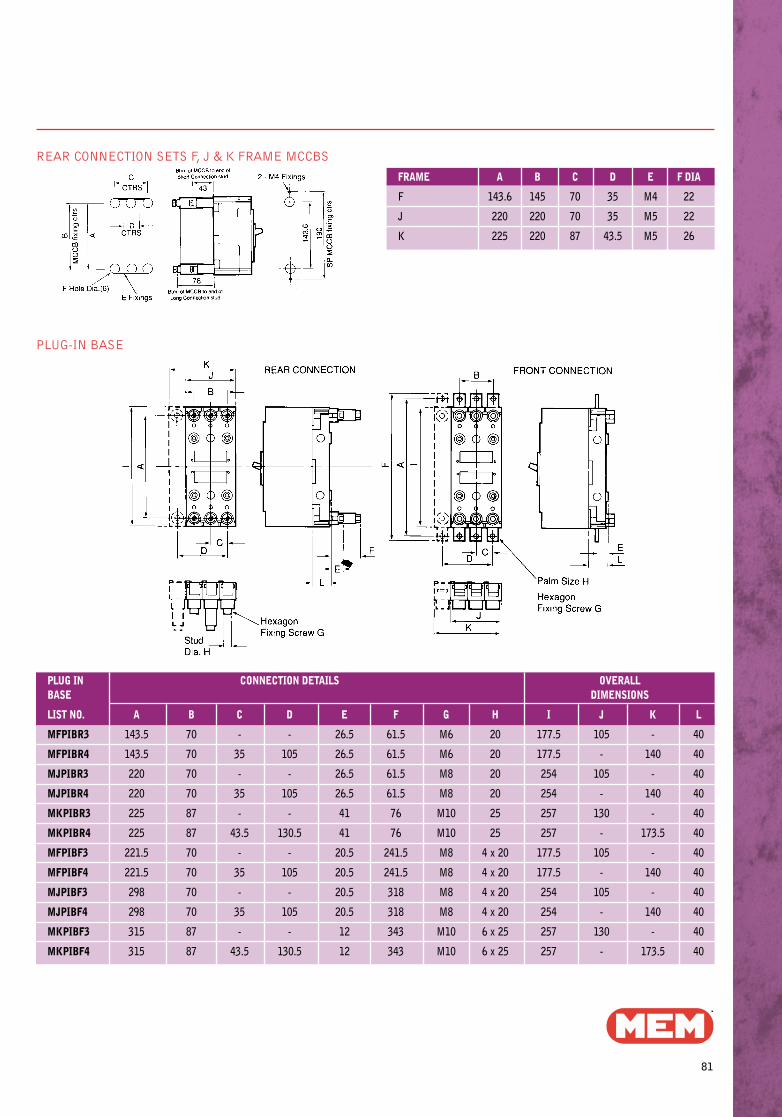
REAR CONNECTION SETS F, J & K FRAME MCCBS
PLUG-IN BASE
PLUG IN CONNECTION DETAILS OVERALLBASE DIMENSIONS
LIST NO. A B C D E F G H I J K L
MFPIBR3 143.5 70 - - 26.5 61.5 M6 20 177.5 105 - 40
MFPIBR4 143.5 70 35 105 26.5 61.5 M6 20 177.5 - 140 40
MJPIBR3 220 70 - - 26.5 61.5 M8 20 254 105 - 40
MJPIBR4 220 70 35 105 26.5 61.5 M8 20 254 - 140 40
MKPIBR3 225 87 - - 41 76 M10 25 257 130 - 40
MKPIBR4 225 87 43.5 130.5 41 76 M10 25 257 - 173.5 40
MFPIBF3 221.5 70 - - 20.5 241.5 M8 4 x 20 177.5 105 - 40
MFPIBF4 221.5 70 35 105 20.5 241.5 M8 4 x 20 177.5 - 140 40
MJPIBF3 298 70 - - 20.5 318 M8 4 x 20 254 105 - 40
MJPIBF4 298 70 35 105 20.5 318 M8 4 x 20 254 - 140 40
MKPIBF3 315 87 - - 12 343 M10 6 x 25 257 130 - 40
MKPIBF4 315 87 43.5 130.5 12 343 M10 6 x 25 257 - 173.5 40
FRAME A B C D E F DIA
F 143.6 145 70 35 M4 22
J 220 220 70 35 M5 22
K 225 220 87 43.5 M5 26
Memshield 2 P47-91 31/7/02 16:16 Page 38
M E M S H I E L D 2 M C C B D I S T R I B U T I O N S Y S T E MM C C B D I M E N S I O N S
82
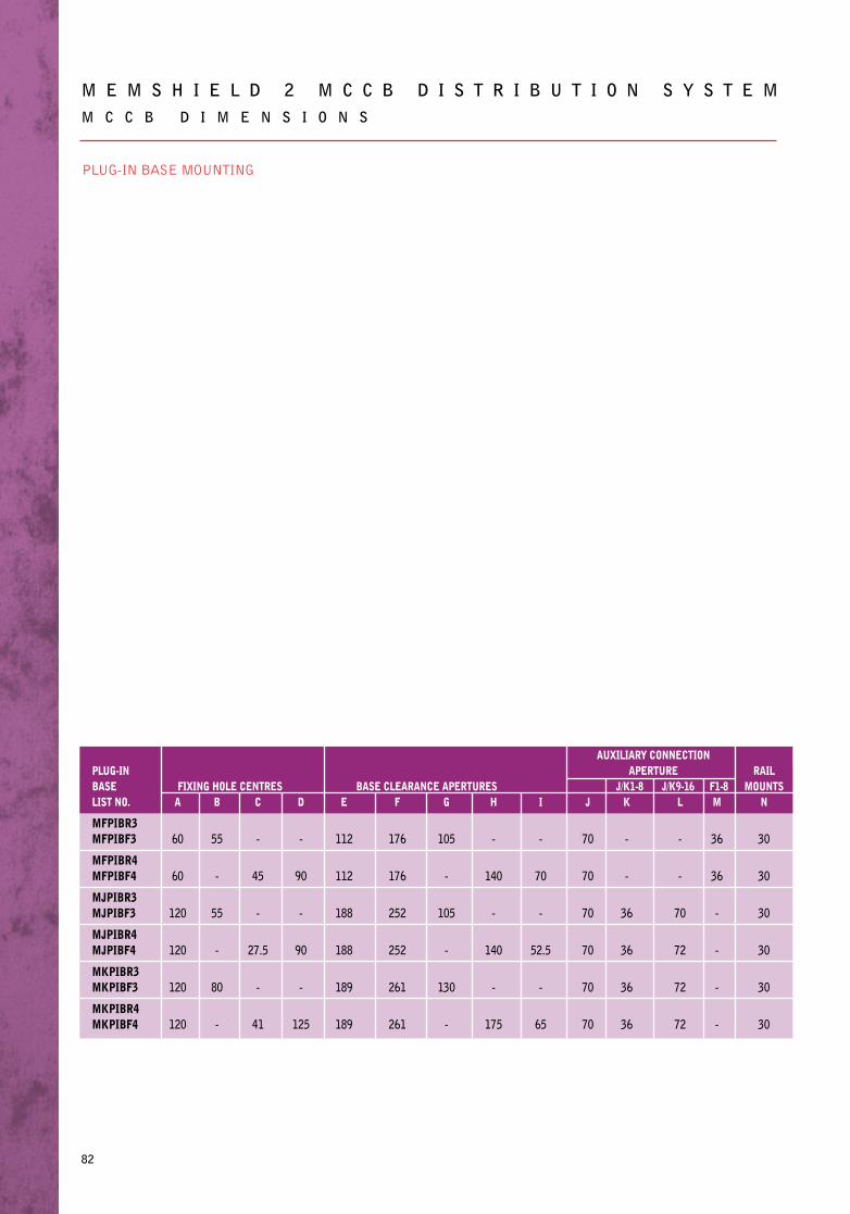
PLUG-IN BASE MOUNTING
AUXILIARY CONNECTIONPLUG-IN APERTURE RAILBASE FIXING HOLE CENTRES BASE CLEARANCE APERTURES J/K1-8 J/K9-16 F1-8 MOUNTSLIST NO. A B C D E F G H I J K L M N
MFPIBR3MFPIBF3 60 55 - - 112 176 105 - - 70 - - 36 30
MFPIBR4MFPIBF4 60 - 45 90 112 176 - 140 70 70 - - 36 30
MJPIBR3MJPIBF3 120 55 - - 188 252 105 - - 70 36 70 - 30
MJPIBR4MJPIBF4 120 - 27.5 90 188 252 - 140 52.5 70 36 72 - 30
MKPIBR3MKPIBF3 120 80 - - 189 261 130 - - 70 36 72 - 30
MKPIBR4MKPIBF4 120 - 41 125 189 261 - 175 65 70 36 72 - 30
Memshield 2 P47-91 31/7/02 16:16 Page 39
83
M C C B D I M E N S I O N S
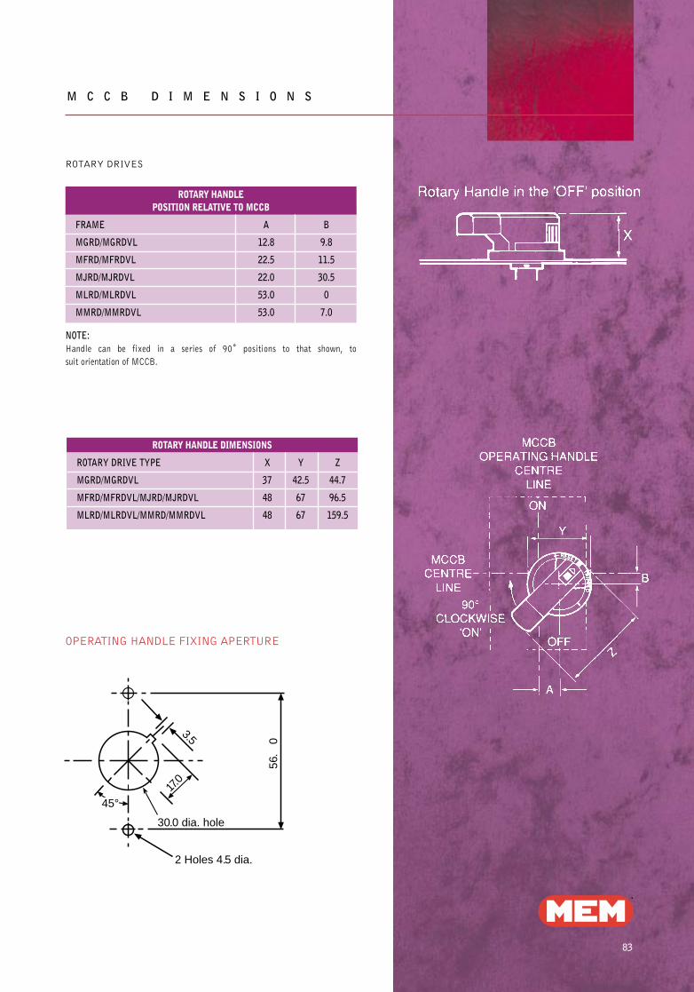
ROTARY DRIVES
ROTARY HANDLEPOSITION RELATIVE TO MCCB
FRAME A B
MGRD/MGRDVL 12.8 9.8
MFRD/MFRDVL 22.5 11.5
MJRD/MJRDVL 22.0 30.5
MLRD/MLRDVL 53.0 0
MMRD/MMRDVL 53.0 7.0
NOTE: Handle can be fixed in a series of 90˚ positions to that shown, to
suit orientation of MCCB.
ROTARY HANDLE DIMENSIONS
ROTARY DRIVE TYPE X Y Z
MGRD/MGRDVL 37 42.5 44.7
MFRD/MFRDVL/MJRD/MJRDVL 48 67 96.5
MLRD/MLRDVL/MMRD/MMRDVL 48 67 159.5
45°
30.0 dia. hole
2 Holes 4.5 dia.
56.
0
17.0
3.5
OPERATING HANDLE FIXING APERTURE
Memshield 2 P47-91 31/7/02 16:17 Page 40
84
M E M S H I E L D 2 M C C B D I S T R I B U T I O N S Y S T E MM C C B D I M E N S I O N S
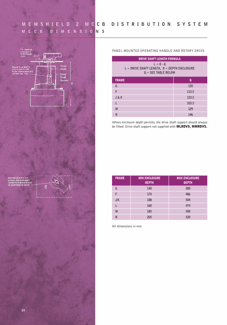
PANEL MOUNTED OPERATING HANDLE AND ROTARY DRIVE
DRIVE SHAFT LENGTH FORMULA
L = D - QL = DRIVE SHAFT LENGTH, D = DEPTH ENCLOSURE
Q = SEE TABLE BELOW
FRAME Q
G 130
F 115.5
J & K 133.5
L 103.5
M 129
N 146
Where enclosure depth permits, the drive shaft support should always
be fitted. Drive shaft support not supplied with MLRDVS, MMRDVS.
FRAME MIN ENCLOSURE MAX ENCLOSUREDEPTH DEPTH
G 140 280
F 170 486
J/K 188 504
L 160 474
M 185 500
N 205 520
All dimensions in mm
Memshield 2 P47-91 31/7/02 16:17 Page 41
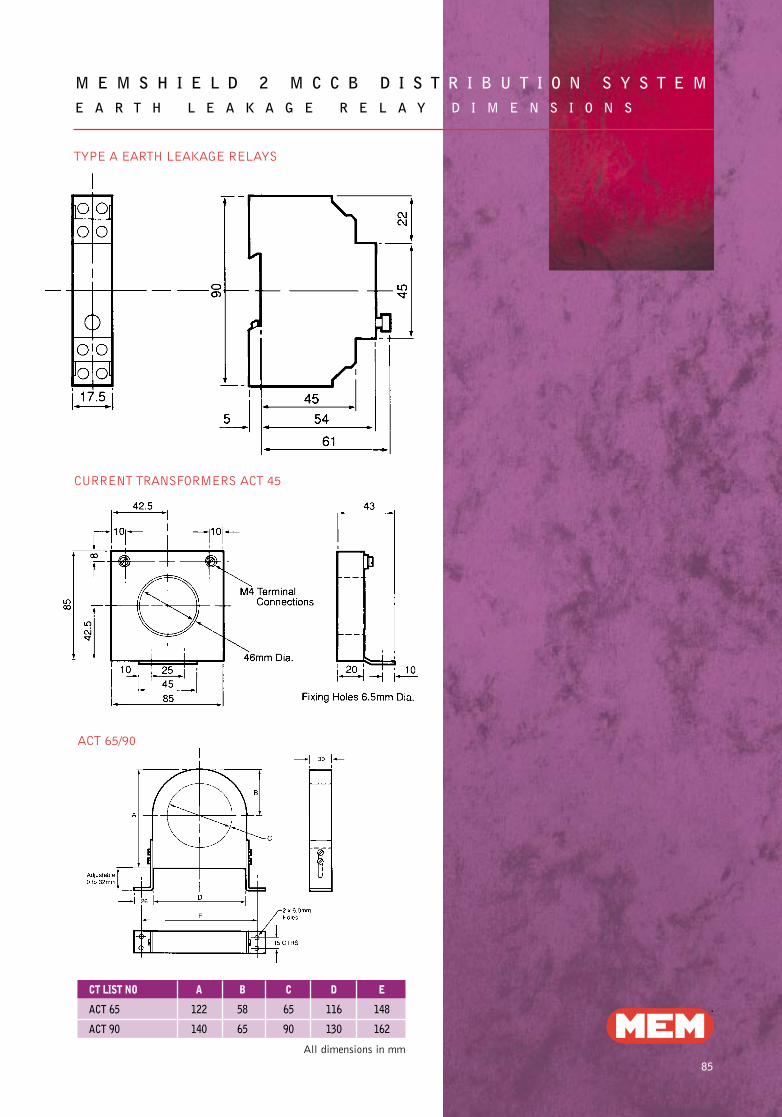
M E M S H I E L D 2 M C C B D I S T R I B U T I O N S Y S T E ME A R T H L E A K A G E R E L A Y D I M E N S I O N S
85
All dimensions in mm
CT LIST NO A B C D E
ACT 65 122 58 65 116 148
ACT 90 140 65 90 130 162
CURRENT TRANSFORMERS ACT 45
TYPE A EARTH LEAKAGE RELAYS
ACT 65/90
Memshield 2 P47-91 31/7/02 16:17 Page 42


![Larbert High School Faculty of Mathematics24453]Higher_Past...2009 P1 Q15 2009 P1 Q21 2010 P1 Q1 2010 P1 Q8 2010 P1 Q21 2010 P1 Q23 2011 P1 Q2 2011 P1 Q8 2011 P1 Q21 2012 P1 Q4 2012](https://img.pdfslide.us/doc/110x75/60bd9bf2b65aaa2b316d3bc9/larbert-high-school-faculty-of-mathematics-24453higherpast-2009-p1-q15-2009.jpg)