Embed Size (px)
Citation preview

Presented at IEEE International Reliability Physics Symposium, San Jose, CA, April 10-13, 2000, pp. 139-145.
MEMS reliability in a vibration environment
Danelle M. Tanner, Jeremy A. Walraven, Karen S. Helgesen, Lloyd W. Irwin,Danny L. Gregory, John R. Stake, and Norman F. Smith
Sandia National Laboratories, P.O. Box 5800, MS 1081, Albuquerque, NM 87185-1081http://www.mdl.sandia.gov/Micromachine
email: [email protected]
ABSTRACT
MicroElectroMechanical Systems (MEMS) were subjected to avibration environment that had a peak acceleration of 120g andspanned frequencies from 20 to 2000 Hz. The device chosen for thistest was a surface-micromachined microengine because it possessesmany elements (springs, gears, rubbing surfaces) that may be sus-ceptible to vibration. The microengines were unpowered during thetest. We observed 2 vibration-related failures and 3 electrical fail-ures out of 22 microengines tested. Surprisingly, the electrical fail-ures also arose in four microengines in our control group indicatingthat they were not vibration related. Failure analysis revealed thatthe electrical failures were due to shorting of stationary comb fingersto the ground plane.
INTRODUCTION
An element of the success of MicroElectroMechanical Systems(MEMS) as they reach commercialization depends on reliabilitystudies and predictions. MEMS are typically classified as sensors oractuators. Brown et al. performed extensive experiments on MEMSacceleration sensors including shock, vibration, temperature cycling,and flight tests on artillery projectiles [1]. He saw promising resultson automobile-grade accelerometers. However, sensors differ frommicroactuators in that they do not have rubbing surfaces. Surfaces inintimate contact during the environmental test may be at risk. Thiswas demonstrated in reports on humidity effects and wear [2, 3].
Microactuators are used to drive many different types of devicesfrom gear trains to pop-up mirrors [4]. During vibration experi-ments by Lee et al. [5, 6], reflected optical patterns from a clampedmicromirror were monitored and were determined to be error freeover a range of frequencies from 200 Hz to 10 kHz. They claim noeffect from vibration of the clamped mirror on this scale.
But what happens when an actuator is not clamped and is free tomove? Vibration causes motion in the actuator promoting the sur-faces to rub and thus mimics normal operation. In addition, vibra-tion perpendicular to the normal operation direction will impactguides or constraints. Both of these effects can generate wear debrisleading to failure. One of the first experiments [7] to show wear as adominant failure mechanism during operation ran polysilicon mi-croturbines [8] and gears at rotational speeds up to 600,000 rpm. Afocused air jet directed at the turbine induced the rotation. Previousexperiments [9] on the lifetime of the Sandia-designed surface-micromachined microengine [10] investigating frequency depend-ence revealed wear as the dominant failure mechanism.
We subjected our MEMS actuator to vibration. The microenginehas springs that flex, guides that can be impacted, and surfaces thatrub making it a good candidate for vibration studies. The resonantfrequency of the microengine (about 1500 Hz) is in the range of our
system-requirement frequencies, which may be of concern. The ob-jective was to determine any susceptibility of the microengine tovibration with the understanding that the results would apply to abroader range of MEMS actuators.
EXPERIMENTAL APPROACH
This study used the electrostatically driven microactuator (micro-engine) developed at Sandia National Laboratories [10]. The micro-engine consists of orthogonal linear comb drive actuators mechani-cally connected to a rotating gear as seen in Figure 1. By applyingvoltages, the linear displacement of the comb drives was transformedinto circular motion. The X and Y linkage arms are connected to thegear via a pin joint. The gear rotates about a hub, which is anchoredto the substrate.
Sample Preparation
Surface micromachined MEMS are mechanical structures fabri-cated from deposited thin films. The structures are encased in sacri-ficial layers (typically SiO2) until ready for use. The oxide film isetched away using hydrofluoric acid (HF) to yield a “released” sam-ple. There are several strong adhesive forces that act on the struc-tures during the drying stage of the release [11]. These include cap-illary, electrostatic, and van der Waals forces. Capillary forcesdominate at these dimensions and processes have been developed to
shuttle
springs
gear and pin jointFigure 1. Sandia microengine with expanded views of the combdrive (top left) and the rotating gear with a pin joint connecting tothe linkage arms.(bottom left).

reduce or eliminate these forces for successful operation of theMEMS structure [12].
Coupling agent coatings such as alkysilanes have been used toincrease the hydrophobicity of the polysilicon surface, thus elimi-nating capillary forces [13, 14]. Application of a coupling agentrequires preparation of the polysilicon surface by an oxidation step(H2O2), resulting in an oxide layer a few nanometers thick. Thesamples in this experiment were coated with such an alkysilane cou-pling agent.
Microengine Vibration Experiment
A die with four microengines was selected for this experiment.There were two microengines driving load gears and two microengi-nes without load gears on the die. These microengine actuators in-cluded clamps to prevent out-of-the-plane motion. The dice wereattached inside a 24-pin DIP ceramic package. A typical packagewithout a cover is shown in Figure 2. The dice were packaged withtaped glass covers during inspection and taped metal covers duringexperimentation to prevent particle contamination.
We used three modes of vibration, designated top/bottom, shortside, and long side shown in Figure 2. With the top/bottom vibra-tion, the moving shuttle could bounce between the ground plane andthe vertical clamps. The motion could lead to possible problemareas of stiction to the substrate or impact wear of the clamps. Themicroengines are fairly well constrained by guides and spring stopsagainst movement in the plane. However, resonance effects, withthe associated large amplitude motions, could well be an issue forthe short side and long side vibrations.
The orientation of the die relative to the vibration is shown inFigure 3. In both long side and short side orientation, actuators willbe vibrated parallel or perpendicular to typical shuttle movement.When the motion is parallel, the shuttle and gear could move, lead-
ing to wear of the rubbing surfaces. However, with perpendicularmotion the shuttle hits the guides, which could promote wear fromimpacting surfaces.
Each functioning microengine was visually inspected and docu-mented before the vibration by capturing nine video images of stra-tegic areas. Four images were captured for each actuator, either X orY, corresponding to different sections of the shuttle and combmechanism. The final image was of the drive gear.
Because we were interested in establishing an upper bound to thesusceptibility of MEMS devices to vibration, we chose a spectrumthat was four times the typical system vibration requirement. Ourdesign stress was a white noise spectrum with frequency componentsfrom 20 Hz to 2000 Hz and a power spectral density of 0.8 g2/Hz.This range includes the resonant frequency of 1500 Hz for the mi-croengine. The duration of the test was three minutes. Although thespectrum is very broad with random input frequencies and randommicroengine responses, most of the vibration-induced oscillationwill occur at resonance [15]. Therefore we can estimate the totalnumber of oscillations to be 1500 Hz × 360 seconds to be 5.4 × 10⁵
cycles. This is equivalent to the typical number of stress cycleswhere we have observed failures due to wear in previous experi-ments [2,9].
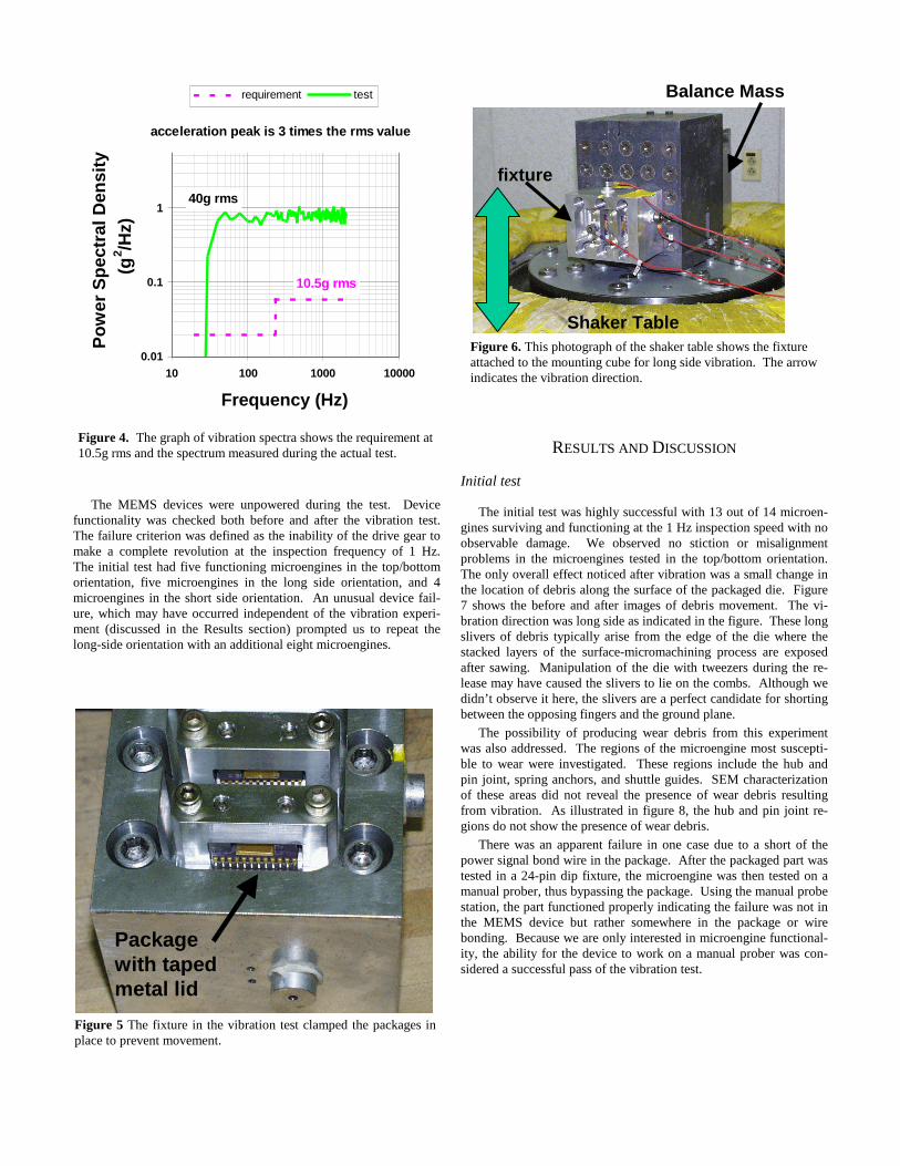
The vibration spectra are shown in Figure 4, which includes atypical system requirement and the actual spectrum measured duringthe test. The rms values were calculated from the square root of thepower spectral density times bandwidth. The peak acceleration istypically three times the rms value, yielding 120g for this test.
The packages were clamped into a fixture as shown in Figure 5.The fixture was then attached to a mounting cube on the shaker tableshown in Figure 6. Accelerometers were attached to the fixture tomeasure the vibration during test. The arrow in the figure indicatesthe vibration direction. The balance mass shown behind the mount-ing cube prevented out-of-plane stray oscillation. The three orienta-tions were achieved by rotating the fixture on the mounting cube.
Short Side
Top/Bottom
Long Side
Figure 2. Photo of a typical packaged die that was vibrated in thethree orientations indicated.
Long Side
ShortSide
Figure 3. Orientation of the die relative to the vibration.
The MEMS devices were unpowered during the test. Devicefunctionality was checked both before and after the vibration test.The failure criterion was defined as the inability of the drive gear tomake a complete revolution at the inspection frequency of 1 Hz.The initial test had five functioning microengines in the top/bottomorientation, five microengines in the long side orientation, and 4microengines in the short side orientation. An unusual device fail-ure, which may have occurred independent of the vibration experi-ment (discussed in the Results section) prompted us to repeat thelong-side orientation with an additional eight microengines.
RESULTS AND DISCUSSION
Initial test
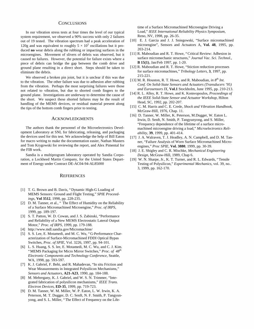
The initial test was highly successful with 13 out of 14 microen-gines surviving and functioning at the 1 Hz inspection speed with noobservable damage. We observed no stiction or misalignmentproblems in the microengines tested in the top/bottom orientation.The only overall effect noticed after vibration was a small change inthe location of debris along the surface of the packaged die. Figure7 shows the before and after images of debris movement. The vi-bration direction was long side as indicated in the figure. These longslivers of debris typically arise from the edge of the die where thestacked layers of the surface-micromachining process are exposedafter sawing. Manipulation of the die with tweezers during the re-lease may have caused the slivers to lie on the combs. Although wedidn’t observe it here, the slivers are a perfect candidate for shortingbetween the opposing fingers and the ground plane.
The possibility of producing wear debris from this experimentwas also addressed. The regions of the microengine most suscepti-ble to wear were investigated. These regions include the hub andpin joint, spring anchors, and shuttle guides. SEM characterizationof these areas did not reveal the presence of wear debris resultingfrom vibration. As illustrated in figure 8, the hub and pin joint re-gions do not show the presence of wear debris.
There was an apparent failure in one case due to a short of thepower signal bond wire in the package. After the packaged part wastested in a 24-pin dip fixture, the microengine was then tested on amanual prober, thus bypassing the package. Using the manual probestation, the part functioned properly indicating the failure was not inthe MEMS device but rather somewhere in the package or wirebonding. Because we are only interested in microengine functional-ity, the ability for the device to work on a manual prober was con-sidered a successful pass of the vibration test.
0.01
0.1
1
10
10 100 1000 10000
Frequency (Hz)
Pow
er S
pect
ral D
ensi
ty
(g2 /H
z)
requirement test
40g rms
10.5g rms
acceleration peak is 3 times the rms value
Figure 4. The graph of vibration spectra shows the requirement at10.5g rms and the spectrum measured during the actual test.
Packagewith tapedmetal lid
Figure 5 The fixture in the vibration test clamped the packages inplace to prevent movement.
Shaker Table
Balance Mass
fixture
Figure 6. This photograph of the shaker table shows the fixtureattached to the mounting cube for long side vibration. The arrowindicates the vibration direction.
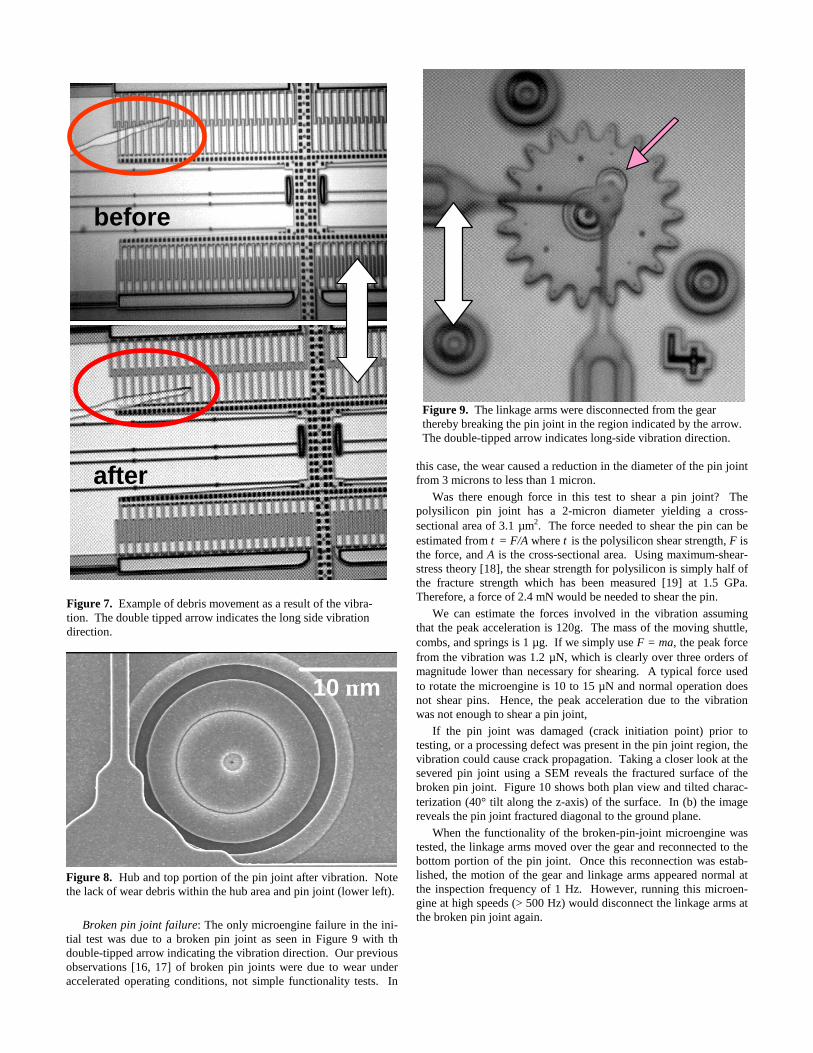
Figure 8. Hub and top portion of the pin joint after vibration. Notethe lack of wear debris within the hub area and pin joint (lower left).
Broken pin joint failure: The only microengine failure in the ini-tial test was due to a broken pin joint as seen in Figure 9 with thdouble-tipped arrow indicating the vibration direction. Our previousobservations [16, 17] of broken pin joints were due to wear underaccelerated operating conditions, not simple functionality tests. In
this case, the wear caused a reduction in the diameter of the pin jointfrom 3 microns to less than 1 micron.
Was there enough force in this test to shear a pin joint? Thepolysilicon pin joint has a 2-micron diameter yielding a cross-sectional area of 3.1 µm2. The force needed to shear the pin can beestimated from τ = F/A where τ is the polysilicon shear strength, F isthe force, and A is the cross-sectional area. Using maximum-shear-stress theory [18], the shear strength for polysilicon is simply half ofthe fracture strength which has been measured [19] at 1.5 GPa.Therefore, a force of 2.4 mN would be needed to shear the pin.
We can estimate the forces involved in the vibration assumingthat the peak acceleration is 120g. The mass of the moving shuttle,combs, and springs is 1 µg. If we simply use F = ma, the peak forcefrom the vibration was 1.2 µN, which is clearly over three orders ofmagnitude lower than necessary for shearing. A typical force usedto rotate the microengine is 10 to 15 µN and normal operation doesnot shear pins. Hence, the peak acceleration due to the vibrationwas not enough to shear a pin joint,
If the pin joint was damaged (crack initiation point) prior totesting, or a processing defect was present in the pin joint region, thevibration could cause crack propagation. Taking a closer look at thesevered pin joint using a SEM reveals the fractured surface of thebroken pin joint. Figure 10 shows both plan view and tilted charac-terization (40° tilt along the z-axis) of the surface. In (b) the imagereveals the pin joint fractured diagonal to the ground plane.
When the functionality of the broken-pin-joint microengine wastested, the linkage arms moved over the gear and reconnected to thebottom portion of the pin joint. Once this reconnection was estab-lished, the motion of the gear and linkage arms appeared normal atthe inspection frequency of 1 Hz. However, running this microen-gine at high speeds (> 500 Hz) would disconnect the linkage arms atthe broken pin joint again.
before
after
Figure 7. Example of debris movement as a result of the vibra-tion. The double tipped arrow indicates the long side vibrationdirection.
Figure 9. The linkage arms were disconnected from the gearthereby breaking the pin joint in the region indicated by the arrow.The double-tipped arrow indicates long-side vibration direction.
10 µm
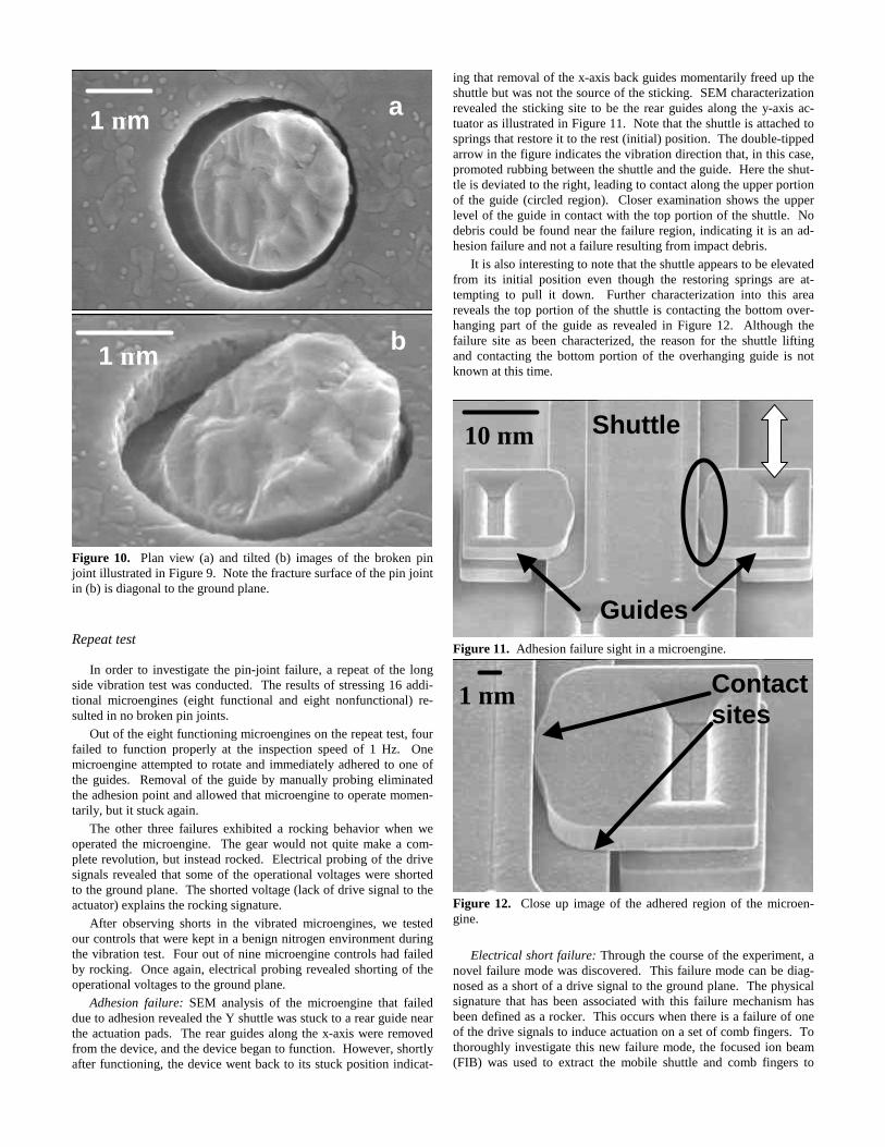
Figure 10. Plan view (a) and tilted (b) images of the broken pinjoint illustrated in Figure 9. Note the fracture surface of the pin jointin (b) is diagonal to the ground plane.
Repeat test
In order to investigate the pin-joint failure, a repeat of the longside vibration test was conducted. The results of stressing 16 addi-tional microengines (eight functional and eight nonfunctional) re-sulted in no broken pin joints.
Out of the eight functioning microengines on the repeat test, fourfailed to function properly at the inspection speed of 1 Hz. Onemicroengine attempted to rotate and immediately adhered to one ofthe guides. Removal of the guide by manually probing eliminatedthe adhesion point and allowed that microengine to operate momen-tarily, but it stuck again.
The other three failures exhibited a rocking behavior when weoperated the microengine. The gear would not quite make a com-plete revolution, but instead rocked. Electrical probing of the drivesignals revealed that some of the operational voltages were shortedto the ground plane. The shorted voltage (lack of drive signal to theactuator) explains the rocking signature.
After observing shorts in the vibrated microengines, we testedour controls that were kept in a benign nitrogen environment duringthe vibration test. Four out of nine microengine controls had failedby rocking. Once again, electrical probing revealed shorting of theoperational voltages to the ground plane.
Adhesion failure: SEM analysis of the microengine that faileddue to adhesion revealed the Y shuttle was stuck to a rear guide nearthe actuation pads. The rear guides along the x-axis were removedfrom the device, and the device began to function. However, shortlyafter functioning, the device went back to its stuck position indicat-
ing that removal of the x-axis back guides momentarily freed up theshuttle but was not the source of the sticking. SEM characterizationrevealed the sticking site to be the rear guides along the y-axis ac-tuator as illustrated in Figure 11. Note that the shuttle is attached tosprings that restore it to the rest (initial) position. The double-tippedarrow in the figure indicates the vibration direction that, in this case,promoted rubbing between the shuttle and the guide. Here the shut-tle is deviated to the right, leading to contact along the upper portionof the guide (circled region). Closer examination shows the upperlevel of the guide in contact with the top portion of the shuttle. Nodebris could be found near the failure region, indicating it is an ad-hesion failure and not a failure resulting from impact debris.
It is also interesting to note that the shuttle appears to be elevatedfrom its initial position even though the restoring springs are at-tempting to pull it down. Further characterization into this areareveals the top portion of the shuttle is contacting the bottom over-hanging part of the guide as revealed in Figure 12. Although thefailure site as been characterized, the reason for the shuttle liftingand contacting the bottom portion of the overhanging guide is notknown at this time.
Figure 11. Adhesion failure sight in a microengine.
Figure 12. Close up image of the adhered region of the microen-gine.
Electrical short failure: Through the course of the experiment, anovel failure mode was discovered. This failure mode can be diag-nosed as a short of a drive signal to the ground plane. The physicalsignature that has been associated with this failure mechanism hasbeen defined as a rocker. This occurs when there is a failure of oneof the drive signals to induce actuation on a set of comb fingers. Tothoroughly investigate this new failure mode, the focused ion beam(FIB) was used to extract the mobile shuttle and comb fingers to
1 µm
1 µm b
a
10 µm
1 µm
Shuttle
Guides
Contactsites

permit unobstructed viewing of the bottom level of polysilicon combfingers. Analysis could be conducted with the shuttle intact, but anydefects that may occur on the bottom level of the comb fingers fromthe side would be obstructed from the comb fingers as illustrated infigure 13.
Front Side
Figure 13. Front and side views of a 40o tilted micromachine combdrive actuator. Note the tips of the comb fingers can be viewed, butthe mobile shuttle obstructs characterization from the side of thestationary comb fingers.
The FIB cuts involved severing nine polysilicon lines as indi-cated by the dark lines of Figure 14. Here, nine FIB cuts were madealong thin regions of polysilicon located at the front and back an-chors (four FIB cuts per anchor). The ninth FIB cut is performed atthe flexure located just before the linkage arm connecting the shuttleto the gear. The released shuttle was then removed from the micro-engine utilizing a probe tip with a sticky adhesive at the tip of theprobe. This method removed the shuttle without inducing damagealong the stationary comb fingers.
Figure 14. AutoCad rendered image of a Sandia fabricated combdrive actuator. Each thick line indicates a region where a FIB cuthas been performed (4 for each spring anchor, and one for the flexarm).
Investigating the electrical short failure using a SEM revealed apolysilicon comb finger adhered to the polysilicon ground plane asshown in Figure 15. Although this failure may appear to be “stic-tion” related, it is not. Stiction-related failures occur predominantlyduring the release process. These microengines were released andcharacterized both optically and electrically. Both inspections didnot reveal the presence of adhered comb fingers. This indicates thecomb finger somehow adhered to the ground plane to induce failureafter the initial inspection.
Upon further SEM inspection, residual material is present at thetip of the comb finger as illustrated in Figure 16. Characterizationand experiments are currently underway to determine if the materialis a result of particular contamination, residue along the comb finger,
or arcing due to electrostatic discharg (ESD). In either case, thedirect result is a short of a bottom comb finger to the ground plane.
Figure 15. Polysilicon comb finger adhered to the ground plane.
Figure 16. Close up SEM image of the adhered comb finger ofFigure 15. Residual material is present at the tip of the comb finger(depicted in the circled region).
Overall failure discussion: At this point, we are unclear if the vi-bration caused the pin joint failure. However, it cannot be ruled out.We categorized this failure mechanism as anomalous since it couldnot be duplicated upon similar experimental conditions. This resultindicates that there may have been an initial flaw in the pin joint, orthe pin joint suffered some form of damage prior to testing which thevibration acerbated.
The adhesion failure was vibration related. The direction of thevibration promoted the rubbing of the moving shuttle and the guide.We suspect that the rubbing caused the adhesion.
Because the three electrical short failures in the repeat test wereduplicated in the controls, we can assume that they were not due tovibration.
In all, we observed two failures out of a total of 19 microenginestested (eliminating the three shorts) which implies a 90% pass ratefor a vibration stress set to four times our typical system require-ment.
FIBCUT
10 µm
10 µm
1 µm
CONCLUSIONS
In our vibration stress tests at four times the level of our typicalsystem requirement, we observed a 90% success with only 2 failuresout of 19 tested. The vibration spectrum had a peak acceleration of120g and was equivalent to roughly 5 × 10⁵ oscillations but it pro-duced no wear debris along the rubbing or impacting surfaces in themicroengines. Movement of slivers of debris was observed, but itcaused no failures. However, the potential for failure exists where apiece of debris can bridge the gap between the comb drive andground plane resulting in a direct short. Steps should be taken toeliminate the debris.
We observed a broken pin joint, but it is unclear if this was dueto the vibration. The other failure was due to adhesion after rubbingfrom the vibration. Perhaps the most surprising failures were thosenot related to vibration, but due to shorted comb fingers to theground plane. Investigations are underway to determine the cause ofthe short. We suspect these shorted failures may be the result ofhandling of the MEMS devices, or residual material present alongthe tips of the bottom comb fingers prior to testing.
ACKNOWLEDGMENTS
The authors thank the personnel of the Microelectronics Devel-opment Laboratory at SNL for fabricating, releasing, and packagingthe devices used for this test. We acknowledge the help of Bill Eatonfor macro writing to make the documentation easier, Nathan Mastersand Tom Krygowski for reviewing the report, and Alex Pimental forthe FIB work.
Sandia is a multiprogram laboratory operated by Sandia Corpo-ration, a Lockheed Martin Company, for the United States Depart-ment of Energy under Contract DE-AC04-94-AL85000
REFERENCES
[1] T. G. Brown and B. Davis, “Dynamic High-G Loading ofMEMS Sensors: Ground and Flight Testing,” SPIE Proceed-ings, Vol 3512, 1998, pp. 228-235.
[2] D. M. Tanner, et al., “ The Effect of Humidity on the Reliabilityof a Surface Micromachined Microengine,” Proc. of IRPS,1999, pp. 189-197.
[3] S. T. Patton, W. D. Cowan, and J. S. Zabinski, “Performanceand Reliability of a New MEMS Electrostatic Lateral OutputMotor,” Proc. of IRPS, 1999, pp. 179-188.
[4] http://www.mdl.sandia.gov/Micromachine/[5] S. S. Lee, E. Motamedi, and M. C. Wu, “G-Performance Char-
acterization of Surface-Micromachined FDDI Optical BypasSwitches, Proc. of SPIE, Vol. 3226, 1997, pp. 94-101.
[6] L. S. Huang, S. S. lee, E. Motamedi, M. C. Wu, and C. J. Kim.“MEMS Packaging for Micro Mirror Switches,” Proc. of 48th
Electronic Components and Technology Conference, Seattle,WA, 1998, pp. 593-597.
[7] K. J. Gabriel, F. Behi, and R. Mahadevan, “In situ Friction andWear Measurements in Integrated Polysilicon Mechanisms,”Sensors and Actuators, A21-A23, 1990, pp. 184-188.
[8] M. Mehregany, K. J. Gabriel, and W. S. N. Trimmer, “Inte-grated fabrication of polysilicon mechanisms,” IEEE Trans.Electron Devices, ED-35, 1999, pp. 719-723.
[9] D. M. Tanner, W. M. Miller, W. P. Eaton, L. W. Irwin, K. A.Peterson, M. T. Dugger, D. C. Senft, N. F. Smith, P. Tangyun-yong, and S. L. Miller, “The Effect of Frequency on the Life-
time of a Surface Micromachined Microengine Driving aLoad,” IEEE International Reliability Physics Symposium,Reno, NV, 1998, pp. 26-35.
[10] E. J. Garcia and J. J. Sniegowski, “Surface micromachinedmicroengine”, Sensors and Actuators A, Vol. 48, 1995, pp.203-214.
[11] R. Maboudian and R. T. Howe, “Critical Review: Adhesion insurface micromechanic structures,” Journal Vac. Sci. Technol.,B 15(1), Jan/Feb 1997, pp. 1-20.
[12] R. Maboudian and R. T. Howe, “Stiction reduction processesfor surface micromachines,” Tribology Letters, 3, 1997, pp.215-221.
[13] M. R. Houston, R. T. Howe, and R. Maboudian, in 8th Int.Conf. On Solid-State Sensors and Actuators (Transducers ’95)and Eurosensors IX, Vol.1 Stockholm, June 1995, pp. 210-213.
[14] R. L. Alley, R. T. Howe, and K. Komvopoulos, Proceedings ofthe IEEE Solid-State Sensor and Actuator Workshop, HiltonHead, SC, 1992, pp. 202-207.
[15] C. M. Harris and C. E. Crede, Shock and Vibration Handbook,McGraw-Hill, 1976, Chap. 11.
[16] D. Tanner, W. Miller, K. Peterson, M.Dugger, W. Eaton L.Irwin, D. Senft, N. Smith, P. Tangyunyong, and S. Miller,“Frequency dependence of the lifetime of a surface micro-machined microengine driving a load,” Microelectronics Reli-ability, 39, 1999, pp. 401-414.
[17] J. A. Walraven, T. J. Headley, A. N. Campbell, and D. M. Tan-ner, “Failure Analysis of Worn Surface Micromachined Micro-engines,” Proc SPIE, Vol. 3880, 1999, pp. 30-39.
[18] J. E. Shigley and C. R. Mischke, Mechanical EngineeringDesign, McGraw-Hill, 1989, Chap 6.
[19] W. N. Sharpe, Jr., K. T. Turner, and R. L. Edwards, “TensileTesting of Polysilicon,” Experimental Mechanics, vol. 39, no..3, 1999, pp. 162-170.