Embed Size (px)
Citation preview

MEMS in Cameras
Vijay Chandrasekharan / Eric Tosaya 5/21/2014

2
Camera Evolution • Evolutionary Challenges
• Miniaturization • Robustness (Drop test) • Photography for everyone • Rough handling conditions (Moisture) • Low cost
• Driving required Innovations • Packaging (integration) • Lens design • Actuator
• Autofocus • Image Stabilization • Zoom
• Imaging software (large pixel data) http://www.acme-ug.org/wp-content/uploads/2013/09/Evolution-of-the-camera.jpg
3
FUTURE VISION: DSC functionality+ in smartphone via mems|cam
13MP+ Camera Module Autofocus (available) Computational Imaging (available) Image Stabilization (possible) Shutter (available) Motion Sensing (available) Optical Zoom
Digital Still Cameras Nikon Coolpix DSC (55x33x14 mm)
Motor Driven Autofocus and Zoom
Voice coil image stabilization
Voice coil shutter

4
GEN2 AF MEMS Device
1mm
GEN3 AF MEMS Device
1mm

5
Prototype lens barrels with MEMS OIS (Optical Image Stabilization) actuator are functional.
Patents filed for new concept Gen4 MEMS actuator
MEMS OIS actuator
Image Stabilization

6
World’s smallest AF cameras Supports 6.5 mm in x-y and no added z height
Actuator is integrated inside the camera’s lens barrel
MEMS AF Camera
MEMS AF Actuator
MEMS Characteristics Payload – 4 mg (> O[102] for other MEMS) Motion – 100 um (~O[102] for other MEMS) Shock – >10000 g shock survivability in a smartphone

7
• MEMS actuator is based on a comb drive • Comb drives are capacitive actuators that utilize electrostatic forces that act between two electrically conductive
combs • Combs are arranged so they never touch • When voltage is applied, it causes the combs to be drawn together, causing movement • The force (and movement) is proportional to the change in capacitance (and voltage applied) between the combs
Electrostatic actuation and position sensing. Ultra- low power.
MEMS Actuator Principle
212
dE dCF Vds ds
= =

8
• MEMS actuators move single lens to achieve high precision auto-focusing • Lens is mounted on the actuator, moving the lens along the optical axis achieve autofocusing • Lens position can be determined by measuring the capacitance of the actuator
When no voltage is applied to the actuators. The lens is positioned at “infinity” mechanical stop position
When voltage is applied to the actuators. The lens is moved toward the “macro” position
MEMS AF Design
9
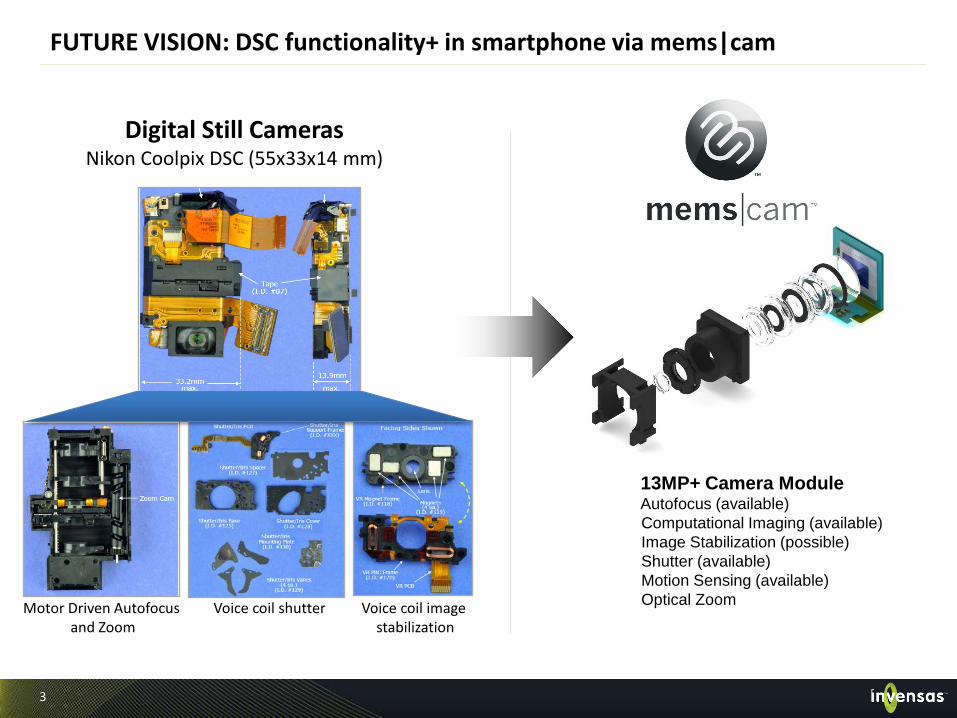
MEMS Design Process
MEMS design process optimization has reduced MEMS design cycle
Able to yield functional silicon on the first design/process verification cycle
Improved ability to predict drop performance from FEA modeling New failure modes can still come
up with new designs Continue to improve our design
checklists and our models
Continue to reduce design and validation cycle time
Product quality is built into the new product development process Design validation combined with process validation Advanced custom tools for MEMS design
Design / model
Error budget Monte Carlo
Flow down specifications
Test Build
Assembly
DESIGN VALIDATION
PROCESS VALIDATION
Product specifications
DESIGN VALIDATION

10
MEMS AutoFocus Actuator

11
MEMS vs. VCM
Voice coil Autofocus MEMS
MEMS is simpler and smaller than today’s Voice coil smartphone Autofocus
8.5 mm x 8.5 mm x 5 mm 12 pieces
6 mm Diameter x 1 mm 3 pieces

12
MEMS vs. VCM
MEMS has 1/5th the dynamic tilt of VCM
Peak Dynamic Tilt: 0.052°
• 5x increase in dynamic tilt = up to 2x worse corner image quality
VCM
Peak Dynamic Tilt: 0.262°
MEMS

13
MEMS vs. VCM
Heat degrades image quality:
Sensor: Noise DOUBLES every 6° Lens: Corner image quality (MTF) drops 5-10% every 10°
*Controlled measurements taken at 100mm focus with open 1/3” 8MP modules. Larger variance expected enclosed in a phone.
VCM
Time (seconds)
Sens
or t
empe
ratu
re (
°C)
MEMS camera runs 20 C cooler than VCM
MEMS

14
MEMS vs. VCM
Focus Dist. Power Consumption (mW)
MEMS A1594 VCM Module 4
10cm 1.0528 123.357
1m 0.9996 55.146
2.5m 1.0024 32.368
Worst case in MEMS modules Best case in VCM modules
MEMS consumes 1/100th the power of VCM Comparison of power consumption with identical hardware (both using
Fujitsu ISP, Sony sensor, and firmware)

15
MEMS vs. VCM
MEMS is at least 2 times faster than VCM MEMS AF running on Fujitsu M9M0 ISP
Autofocus Speed (10cm to 1.2m)

16
MEMS Actuator Performance • At the threshold voltage, actuator starts to move (17 V in example) • Above the threshold, position is changed by adjusting voltage
• Motion is highly repeatable (multiple curves overlap in example) • Virtually no hysteresis (blue curve is increasing voltage, red is decreasing)
• Actuator is designed to operate up to 33 V but is used up to 31.5 V • Capacitance can be used to determine actuator movement.

17
Design Characteristics Stage is robust, repeatable, precise 8F/706 – validated by customer
Capacitance stability 1% (not hermetically
sealed)
Symmetric design keeps lens centered and
fingers centered at all times
High aspect ratio flexures (> 20:1)
Stiffness in travel (z) direction is >1,000 times
softer than in all other (5) degrees of freedom Ensures precise linear motion in z direction
Electrostatic actuation and position sensing
Payload – 4 mg (>100X for other MEMS)
Motion – 100 um (~100X for other MEMS)
Shock – >10000 g shock survivability in a smartphone
BEST COST/PEFORMANCE AF SOLUTION

Thank You