Embed Size (px)
Citation preview
Sensors 2011, 11, 1433-1460; doi:10.3390/s110201433
sensors ISSN 1424-8220
www.mdpi.com/journal/sensors
Review
MEMS-Based Power Generation Techniques for Implantable
Biosensing Applications
Jonathan Lueke and Walied A. Moussa *
Department of Mechanical Engineering, University of Alberta, University of Alberta, Edmonton,
Alberta T6G 2G8, Canada; E-Mail: [email protected]
* Author to whom correspondence should be addressed; E-Mail: [email protected];
Tel.: +1-780-492-6027.
Received: 29 October 2010; in revised form: 21 January 2011 / Accepted: 23 January 2011 /
Published: 26 January 2011
Abstract: Implantable biosensing is attractive for both medical monitoring and diagnostic
applications. It is possible to monitor phenomena such as physical loads on joints or
implants, vital signs, or osseointegration in vivo and in real time. Microelectromechanical
(MEMS)-based generation techniques can allow for the autonomous operation of
implantable biosensors by generating electrical power to replace or supplement existing
battery-based power systems. By supplementing existing battery-based power systems for
implantable biosensors, the operational lifetime of the sensor is increased. In addition, the
potential for a greater amount of available power allows additional components to be added
to the biosensing module, such as computational and wireless and components, improving
functionality and performance of the biosensor. Photovoltaic, thermovoltaic, micro fuel
cell, electrostatic, electromagnetic, and piezoelectric based generation schemes are
evaluated in this paper for applicability for implantable biosensing. MEMS-based
generation techniques that harvest ambient energy, such as vibration, are much better
suited for implantable biosensing applications than fuel-based approaches, producing up to
milliwatts of electrical power. High power density MEMS-based approaches, such as
piezoelectric and electromagnetic schemes, allow for supplemental and replacement power
schemes for biosensing applications to improve device capabilities and performance. In
addition, this may allow for the biosensor to be further miniaturized, reducing the need for
relatively large batteries with respect to device size. This would cause the implanted
biosensor to be less invasive, increasing the quality of care received by the patient.
OPEN ACCESS
Sensors 2011, 11
1434
Keywords: power micro-generation; implantable biosensors; photovoltaic; thermovoltaic;
micro fuel cell; electrostatic; electromagnetic; piezoelectric
1. Introduction
Microelectromechanical Systems (MEMS)-based sensors are gaining notoriety for biosensing
applications due to their small size, low power consumption, and high integratability into
microelectronic systems for implantable sensing applications. Generally MEMS devices have one, if
not all, of their major dimensions in the micrometer range, many being not much bigger than a few
tens of cubic millimetres when packaged. For implantable applications, MEMS-based devices can be
used in a multitude of roles such as sensing a variety of different phenomena including physical loads
on joints or implants, vital signs, measuring bone density, or osseointegration; enabling targeted drug
delivery; and diagnosis through lab-on-a-chip devices. This is attractive for bio-applications since
these MEMS-based devices are less invasive to implant than larger macro-scale sensing devices,
allowing them to be implanted at a variety of locations in the body where macro-scale devices may not
be suitable. In addition, MEMS-based devices have very low power consumption, which when coupled
with active power management, allows the implantable MEMS-based biodevices to operate for long
periods of time.
The most common method to power MEMS-based in-vivo devices is a conventional or thin film
battery. Normally, the battery system becomes a limiting factor to the lifespan and applicability of
many microbiosensors. Although some biocompatible batteries may have long life spans, the battery
will eventually require replacement or recharging. For short term applications, a battery may thus
provide a sufficient device lifespan, but for long term or high duty cycle applications, alternative
power schemes may be preferable to replacing dead batteries, especially if the replacement/recharge
procedure is invasive. For example, pacemakers are a common implantable system that requires an
independent power source that functions completely autonomously from the outside world. The current
standard for pacemaker operation is to utilize a high-life battery that supplies approximately 0.65
to 2.8 Ampere hours for 5.1 to 9 years [1]. Eventually, the battery for this system will need to be
replaced, requiring additional surgery. Although a pacemaker is not necessarily a biosensing device, or
a MEMS scale device, the power supply has been augmented by an electromagnetic-based MEMS
generator. Roberts et al. [2] developed a system by which an electromagnetic MEMS-based generator
captures the vibrational energy produced by the heart muscle to generate power to supplement the
pacemaker’s internal battery. In initial clinical trials, it was possible to produce up to 17% of the
energy required to operate a conventional pacemaker [2]. Further development of this technology may
be able to eliminate the costly and invasive surgeries required to maintain the pacemaker, both
decreasing medical cost and improving the quality of care for the patient. A direct analogy can be
drawn to the possible applications of this strategy to implantable biosensing. Any number of
implantable biosensing platforms could have their power systems replaced or augmented by MEMS-
based power generators. The addition of MEMS-based generators to the conventional power systems
of these sensors would allow for increased lifespan and the ability to add components to the sensing
Sensors 2011, 11
1435
platform that may have been too energy-costly to initially add to the system. Additional hardware
could also be integrated into these sensing packages, allowing for wireless communications and
on-board computing to further increase the functionality and usefulness of said MEMS-based
implantable sensors.
Although micro scale power generation has many forms, the same general operational principles are
used as in macro scale power generation—a specific form of energy is converted into electricity via a
specific physical phenomenon. The major difference between micro and macro scale power generation
is the scale at which the generation takes place. As you decrease the size of a device into the micro
regime; the relative strengths of all physical forces changes. For example, highly length-dependant
forces, such as electrostatic forces, become increasingly dominant over gravity. Therefore, the MEMS
devices are more likely to be influenced by what would be considered to be ambient forces on a macro
scale. Ambient forces and energy are non-negligible for MEMS devices, and in some cases, this
ambient energy can be harvested by micro generation techniques to produce electricity. Ambient light
energy may be converted into electricity using photovoltaic cells [3-13]. To convert ambient thermal
energy to electricity, thermoelectric generators may be used [14-22]. In addition to scavenging
techniques, chemistry-based techniques, such as micro fuel cells [13,23-35] can be used to supplement
battery-based power schemes. Micro fuel cells use a variety of electrochemical reactions to produce
electricity. Some micro fuel cells can regenerate their fuel and oxidation agents through the
electrochemical reactions that take place within the fuel cell allowing for long term operation [13,23-35].
Vibration is converted to electricity via electrostatic [4,36-47], electromagnetic [2,48-54], and
piezoelectric microgenerators [55-67].
In the following sections each of the above micro-generation methods will be examined in detail.
The relative applicability of these methods will be evaluated and discussed, highlighting both strengths
and weaknesses for various generation physics in various applications. It will be shown that for various
ambient energy types, quantities of ambient energy, and environmental conditions certain methods of
MEMS-based generation will be more suitable for generation of power for implantable biosensing
applications.
2. Methods of Micro-Generation
2.1. Photovoltaic Generation
Photovoltaic cells are the most recognizable energy scavenging technique currently in use, both in
small and large scale applications, ranging from hand-held calculators to commercially generated
electricity. MEMS-based solar cells are based upon electronic asymmetry, such as a p-n junction found
in semiconductors. As this electrical asymmetry is illuminated, incident photons cause electron hole
pairs to form, promoting local electron mobility. If connected to a load, free electrons will flow
through the load and then back to the solar cell, where vacant electron holes are located [3]. In order
for photovoltaic cells to be efficient, they must be placed in direct, bright sunlight. Without direct, high
intensity light, the generating capacity of a photovoltaic cell can diminish significantly
from 15 mW/cm2 in direct sunlight to 10 μW/cm
2 in normal office lighting [4]. Photovoltaic cell
materials need to be carefully chosen, since the measured output power can vary over three orders of
Sensors 2011, 11
1436
magnitude at low illumination levels [5]. MEMS-based solar cells can be fabricated from a variety of
materials, including single crystal silicon, thin film polysilicon, gallium arsenide, cadmium telluride,
hydrogenated amorphous silicon and ferroelectric films such as lead lanthanum zirconate titanate
(PLZT) [3,6,7]. These materials are chosen due to their suitable semiconductor band gaps
of 1.4–1.6 eV [3]. Solar cells using the hydrogenated amorphous silicon, such as those developed by
Lee et al. [3], produce a usable amount of electrical power, due to the large band gap (1.55 eV) present
in the hydrogenated amorphous silicon. The solar cell can produce open circuit voltages of 1.5 V per
cell in series and short circuit current of 0.28 µA per cell.
Indium gallium arsenide photogenerators have been developed for use in fiber optic networks to
power optical switches and controllers far down-cable. The ability of photoelectric generators based
upon harvesting light energy from fiber optic cables may allow for the use of photoelectric-based
generators in vivo. The required high intensity light may be channeled to the subcutaneous implant by
collector and fiber optic cable, possibly removing the requirement for direct light. High efficiency
photodiodes are available for this application [8-10] which convert the long wavelength
light (1,300–1,550 nm) into electricity. These photodiodes are high efficiency, but the voltage
available from these relatively small band gap diodes is too small for many switching and controlling
applications. Dentai et al. connected 30 diode segments in a favorable configuration in order to
increase the overall electricity generation from approximately one volt, to 10.5 V at 500 µW,
converting 1,554 nm incident light [11]. The photodiodes are arranged in pie-segments, 30 pie-shaped
photodiodes that are arranged in a complete circle. This arrangement allows for increased conversion
area, reduction of contact resistance, the ability to use anti-reflection coatings on the incident surface
of the photodiode, and the ability to metalize the backside of the photodiode to allow unconverted light
to have a second pass through the photodiode [11]. Similar photovoltaic cells fabricated from gallium
arsenide have generated upwards of 1 W of electrical power using concentrated incident light as a
power source [12].
Solar-based schemes also can use photosynthesis as the driving force behind micro-generation in a
hybrid photoelectric fuel cell [13]. A photosynthetic electrochemical fuel cell has been developed,
where sub-cellular thylakoid photosystems isolated from spinach cells provide the chemical reactions
necessary to generate electricity. During photosynthesis, water is split to produce protons (H+) and
electrons which are both collected by the anode of the cell. The current that is drawn from the anode is
then used in a device, and then returned to the cell through the cathode of the cell, either reducing O2
or regenerating the ferricyanide used in the cell as charge carriers. This process not only produces
electricity for use in a device, but regenerates the chemical reagents used in the initial reaction. This
photo-driven fuel cell can produce power densities of up to 5.4 pW/cm2 [13]. For biological
applications the photosynthesis-based micro fuel cell is attractive for its biocompatibility, having no
bio-incompatible fuels or chemical reactions.
2.2. Thermoelectric Generation
Direct thermoelectric generators utilize the Seebeck Effect to generate electricity. The Seebeck
Effect is the direct conversion of a temperature difference into an electrical potential between a
material pair junction [14,15]. Thermoelectric generators made from thermocouples made of aluminum
Sensors 2011, 11
1437
and n-poly-Si, p-Bi0.5Sb1.5T3, and n-Bi0.87Sb0.13 were developed by Huegsen, Woias, and
Kockmann [14,15]. In this case, thin film thermocouples of the above composition were fabricated,
and then connected in series to form thermopiles. In order to maximize the power generation of the
thermoelectric generator, a large thermal contact area is required. To allow for a large thermal contact
area, the heat flow path is guided by thermal connectors to be perpendicular to the surface of the
thermopiles. This method shapes the thermal profile of the thermopile, allowing for 95% of the entire
temperature difference to be located between the two thermopile junctions, which in turn maximizes
the possible heat that can be used in conversion. Power factors as high as 3.63 × 10⁻³
W/mm2K
2
and 8.14 × 10⁻³
W/mm2K
2 can be achieved through this method [14,15]. Direct thermoelectric
generation is considered to be an energy scavenging technique, since waste heat is an abundant energy
source. As long as heat energy is available to the microgenerator, energy conversion will continue
without interruption. The maximum energy that could be converted from thermal to electric energy is
determined by the Carnot efficiency of the generating situation [16]. Since the efficiency of the
thermal-to-electricity conversion is limited by the Carnot efficiency, small thermal gradients will not
be efficient in producing electricity. For thermopile arrays, it has been reported for temperature
differences of 180 °C (200–20 °C) the efficiency of the thermopile array is 10%. In comparison for a
temperature difference of 20 °C (40–20 °C), the same thermopile array has an efficiency
of 1% [16,17].
Thermoelectric generators using the human body as a heat source have been explored by
Leonov et al. [18]. With a wide range of tissues and fluids with each having their own unique material
and thermal properties, it was found that the human body has an inherent non-uniform temperature
distribution. Thermal profiles in different regions of the body may vary due to proximity to blood
vessels and function of surrounding tissues and organs. The variation of thermal characteristics of the
body extends even to the skin and extremities of the body. Areas such as wrists and ankles will be
considerably warmer due to the proximity of major blood vessels to the skin and the external
environment, therefore it is advantageous to strategically place thermoelectric generators in these
locations to maximize generation [18]. The microgenerator itself is a microfabricated array of
polysilicon-germanium (poly-SiGe) thermocouples, which are sandwiched between two silicon wafers
and interconnected in series to form thermopiles. The microgenerator was integrated into a
wrist-mounted package approximately 3 × 3 × 1 cm3 in size, in order to allow for heat absorption
directly from the radial artery of the wrist [18]. These poly-SiGe thermopiles can produce upwards
of 4.5 µW/cm2 of power on the radial artery [18]. This location was chosen since it has the maximum
temperature difference between the body and the outside environment, thus maximizing generation. A
second thermoelectric generator was produced with commercially available BiTe thermopiles that were
developed for the same application for comparison, using a similar wrist mounted package. Poly-SiGe
thermopiles are a more cost effective and mature technology in comparison to the BiTe thermopiles.
However, the BiTe thermocouple-based thermoelectric generator was able to produce on average 100 µW
of power, which was then stored in 2 NiMH batteries. The BiTe microgenerator was composed
of 128 BiTe thermocouples, forming 48 thermopiles, taking a volume of 8.2 × 8.9 × 2.4 mm3 [18].
In comparison, the BiTe-based thermoelectric generator produced a power density of
approximately 571 µW/cm2, in comparison to the poly-SiGe thermoelectric generator that
produced 4.5 µW/cm2. The volume savings of using a more effective thermocouple is significant in
Sensors 2011, 11
1438
this case, the BiTe-based thermogenerator producing a much higher power density with a much
smaller device. This technology has been adapted for wrist watches, and is currently being used by
multiple commercial watch companies in thermo-electrically driven watches. It has been reported that
up to ten similar thermoelectric modules as the above are used to produce the required electricity to
power these watches [16].
In addition to direct thermoelectric conversion, there has been work dedicated to the direct
conversion of heat to mechanical actuation, which is then converted into electricity using a secondary
conversion mechanism [19]. Instead of converting heat energy to electricity and then using the
electricity to actuate a MEMS device, careful selection of geometries and materials can allow for
controllable actuation directly from thermal expansion. This can allow for both in plane and out of
plane linear actuation. To achieve out of plane displacement, two similarly shaped cantilever beams
are fabricated one on top of the other. The top beam is approximately 25% thinner than the bottom
beam. When connected to each other at their respective free ends forming a U-shape, the thermal
expansion of these cantilever beams becomes linked. Therefore, as this structure is heated, asymmetric
thermal expansion between the two connected beams allows for the U-shaped structure to actuate out
of plane. To achieve in plane actuation, cantilever beams are connected perpendicularly to an actuator.
The beams are constrained versus axial thermal expansion. When heated, these beams will expand, and
eventually will start to buckle. This symmetric thermal expansion and buckling will actuate the central
beam in-plane [19]. In addition, rotation may be achieved through the use of micro heat engines,
including Brayton Cycle micro-gas turbine engines [20] and Otto Cycle based heat engines [21], both
directly converting hydrocarbon fuels into rotary motion. Although these thermal-based actuation
schemes do not directly produce electricity, it is possible to use these systems as another actuation
method for various other generation techniques. For example, the linear actuation schemes can be used
to actuate electrostatic, electromagnetic, and piezoelectric based generation schemes. The rotary
actuation schemes can be used to actuate rotary electromagnetic MEMS-based generation schemes.
Thermoelectric generation also entails the use of heat engines to produce electricity on a micro
scale. Heat engines, such as the P3 micro heat engine developed by Whalen et al. [22], can convert
hydrocarbon fuels to electricity on a micro scale. The P3 heat engine is comprised of two major
systems: A combustion chamber that produces heat for the engine and a two-phase working fluid that
provides a pressure load to a piezoelectric membrane when heated. The heat supplied to the two-phase
working fluid causes the fluid to expand and apply pressure to a piezoelectric membrane. The
piezoelectric membrane converts that mechanical strain into electricity via the piezoelectric effect. The
heat engine has a four phase working cycle: Compression, isothermal high temperature heat addition,
expansion, and isothermal low temperature heat rejection. The piezoelectric membrane is deflected
during the compression and expansion phases experienced by the two-phase working fluid. For
characterization, a resistance heater was used to provide the thermal energy required in order to actuate
the piezoelectric membrane. The resistance heater was operated using a square wave, with a 1 ms pulse
width, at voltage amplitude of 3.2 V. The resistance heater, having a resistance of 1.7 Ω,
delivered 1.45 W of thermal energy to the working fluid. The piezoelectric membrane produced a
voltage varying between 63 and 135 mV at a frequency of 240 Hz. With a load resistance of 14 kΩ, the
P3 heat engine produced 0.8 µW at these conditions.
Sensors 2011, 11
1439
2.3. Micro-Fuel Cells
Micro fuel cells operate by harvesting electrons from controlled electrochemical reactions.
Depending upon the fuel and oxidizing agents reacting in the micro fuel cell, it can be considered
either a regenerative or non-regenerative generation technique. If the electrochemical reactions that
take place are self-sustaining, such that the reactants are not irreversibly consumed, the fuel cell is
regenerative. For example, glucose-based, self contained fuel cells [23] are completely regenerative,
able to operate for extended periods of time without outside intervention. The electrochemical
reactions that take place in the glucose-based fuel cell can occur continuously without exhausting fuel
or oxidation chemical supplies. Non-regenerative fuel cells usually have solid oxide fuels, methanol, or
hydrogen as a fuel utilizing a non-reversible reaction to produce free electrons. These fuels have higher
energy densities but consume the fuel as the electrochemical reaction takes place. These
non-regenerative fuel cells produce power as long as there is fuel present.
Glucose based micro fuel cells for biomedical applications are well researched. This type of fuel
cell relies on the electrochemical reaction of oxygen and glucose – two substances commonly found in
the body. For in vivo applications, a glucose-based fuel cell could potentially have an unlimited fuel
supply [23]. Glucose-based fuel cells can be categorized into three specific types: enzymatic, microbial
and abiotic. Enzymatic refers to glucose fuel cells that employ enzymes in order to facilitate the
required chemical reactions to produce electricity. Microbial glucose fuel cells employ specific
micro-organisms that convert the glucose found in a system to electricity [13]. Abiotic fuel cells use
non-biological catalysts in order to ensure that conversion of glucose to electricity takes place. As in
all fuel cells, electricity is generated by the electrochemical reaction of a fuel and an oxidant at two
separated electrodes. Regardless of the fuel or the method of which is taken to catalyze the reaction,
electrons released from the oxidation of the fuel are collected by the anode, flow through the load to
the cathode, upon where a terminal electron acceptor is reduced. The electron flow is driven by the
difference in electrochemical potential of the anode and cathode redox pairs [24]. One molecule of
glucose can be completely oxidized into carbon dioxide and water, releasing 24 electrons per
molecule, as shown below [24]:
Annode: C6H12O6 + 24OH− 6CO2 + 18H2O + 24e
− (1)
Cathode: 6O2 + 12H2O + 24e− 24OH
− (2)
Overall: C6H12O6 + 6O2 6CO2 + 18H2O (3)
Theoretically, it is possible to collect and use all 24 electrons that are generated in this reaction.
However, in practice this has not been achieved [24]. In addition, this single reaction would generate a
theoretical voltage of 1.24 V [24]. The major attraction for the glucose fuel-cell is the fact that the fuel
and the reaction products are highly biocompatible; therefore it can be considered for in vivo
MEMS-based applications. Glucose-based micro fuel cells have been reported to produce 50 µW/cm2
to 430 µW/cm2 for long-term constant generation [25].
Solid oxide fuel cells (SOFC) have also been developed [26]. These fuel cells use a novel
microfabrication method of directly printing the anodes and cathodes used in this system in specific
configurations. They are deposited using a direct-write system, where suspensions of 55 wt%
Sensors 2011, 11
1440
NiO/45 wt% YSZ (anode) and (La0.8Sr0.2)0.98MnO3 (cathode) powders are deposited as a paste onto the
fuel cell’s surface through a robotically controlled micronozzle system. This allows for a variety of
possible electrode configurations, maximizing electrode/reactant surface area contact. In addition, by
using these specific electrode materials, it is possible to use hydrocarbons as a fuel in this fuel cell
since the operational temperature of this fuel cell can be significantly higher than fuel cells composed
of other materials. Hydrocarbon-based fuel cells have higher energy densities than other fuel cells [27].
A mixture of methanol and air is used as the fuel in this fuel cell which produces an open circuit
voltage of 0.9 V and a peak power density of 2.3 mW/cm2 at 700 °C. This type of micro fuel cell has a
much higher operational temperature than the previous ones, but produces much more usable
energy [26]. When applied to other types of fuel cells, this approach may help with further
miniaturization and optimization of power output, especially for size critical in-vivo applications.
Direct Methanol Fuel Cells (µDMFC) are another type of fuel cell of interest. Common power
generation values range from 200 mV–1 V, and microwatts of power. For example, a micro fuel cell
developed by Sim, Kim and Yang for the biological application uses methanol as a fuel [28]. Although
methanol is toxic to biological systems, it is a good example of the technology. The operation of these
systems is based on the electrochemical reaction shown below:
CH3OH + H2O CO2 + 6H+ + 6e
− (4)
The µDMFC is a type of Proton Exchange Membrane Fuel Cell (PEMFC) [29], which not only
relies on the collection of electrons at the anode to produce a current, but the migration of protons (H+)
to the cathode where catalysts allow the hydrogen to form water, completing the electrical circuit. A
limiting factor to the application of these devices in their current state is their size. Currently, a
common size for these devices is 16 × 16 × 1.2 mm, which may be too large for some implantable
biosensing applications. Another limiting factor to the lifespan of the device, barring any physical
damage, is the amount of fuel available to the system [30]. As long as the fuel cell has a sufficient
supply of fuel, it will produce electricity uninterrupted. Generally, this type of fuel cell is constructed
of two silicon wafers with a membrane electrode assembly patterned onto a membrane, such as Nafion,
sandwiched in between. The silicon wafers are micromachined with through-holes in order to allow
both the methanol fuel and oxygen catalyst to reach the membrane/electrode assembly to allow for the
electrochemical reaction to take place [29]. The through hole or microchannels are designed to be very
small, roughly 80 × 80 µm, to ensure that the capillary forces allowing the methanol to be passively
transported to the membrane/electrode assembly are prevalent over gravity forces, which would
otherwise prevent fuel flow in certain orientations of the micro fuel cell [31]. This type of passive
µDMFC is able to produce 9 mW/cm2 for about 50 minutes operation—the time required to exhaust
the methanol fuel source [29].
Motokawa et al. [32] have developed a novel parallel microchannel system for µDMFCs that allows
for a greater active area on the membrane interface that transports protons. The micro fuel cell is
composed of two parallel microchannels, connected on the top surface by a DuPont
Nafion 112 proton membrane. The multiple anodes and cathodes used in this micro fuel cell are
located on the bottom and sides of the microfluidic channels, which allow for high efficiency
collection of electrons by the anodes and high efficiency transportation of protons to the cathodes. The
travel distance from anode to cathode is very short; this causes the system to be less sensitive to ohmic
Sensors 2011, 11
1441
impedance [32]. In addition, this approach isolates the fuel and oxidant in the fuel cell, preventing any
cross-mixing of fuel and oxidant that may occur in other fuel cells. This novel technique prevents some
traditional problems in micro fuel cell design, but does not produce as much power as other designs,
only producing 0.78 mW/cm2 [32]. In addition to travel distance, the geometry of the fuel cell plays an
important role in the efficiency and generation potential of the µDMFC. Generally, the anode flow
field plate is designed to maximize the surface area upon which the required electrochemical reactions
take place. By maximizing the surface area upon which the reaction can take place, using a double
serpentine structure rather than a pin-type flow plate, the peak power output of the µDMFC can be
increased by upwards of 20.7% [33].
In addition to previous schemes used to increase the surface reactive area of fuel cells, stacks of fuel
cells can be arranged in a ―flip flop‖ configuration [34] where a common bipolar plate, containing both
an anode and cathode, can be used to achieve long continuous stacks of fuel cells. By connecting one
anode side of a common plate to a cathode side of a different common plate, long stacks can be
created, increasing the generation potential of that single, ―flip flopped‖, fuel cell. This scheme
minimizes the connection resistance of the system. This scheme, when fueled with 2 M methanol,
produced 2.7 V of open circuit voltage, with a peak power output density of 2.2 mW/cm2 [34].
Carbon Nanotubes have been perused as both a catalyst support layer and a gas transport method for
micro-fuel cells [35]. A honeycomb-type arrangement of carbon nanotubes is used to transport both the
fuel and oxidant between reaction sides of the fuel cell. In this case, an air/hydrogen mixture is used as
fuel. Studies conducted by Kuriyama et al. [35] focused on demonstrating that carbon nanotubes were
a viable structural material for both material transport and as a support layer. The micro fuel cell using
carbon nanotubes as a transport medium for catalysts was able to produce an energy density
of 0.75 W/cm2 [35]. The carbon nanotube transport system also allowed for a more uniform and
predictable transportation of materials around the fuel cell. In traditional fuel cells, pressure driven
diffusion across a membrane is the primary method of reactant transportation. With carbon nanotubes,
it is possible to easily transport materials without a pressurizing mechanism, allowing for greater
reliability and standardization of specifications between similar fuel cells [35].
2.4. Electrostatic Vibration-to-Electricity Conversion
Electrostatic vibration-to-electricity energy harvesting most often utilizes a comb drive to generate
electricity from a base vibration. With these devices, power is generated through a vibration-driven
capacitance variance which causes charge transfer and current flow. The capacitors must be held at a
constant charge to promote power generation, therefore a polarization source must be present in order
to generate additional power. The charge required for the system to operate can be supplied actively
from a power source or passively through use of an electret layer [36,37] or a charge pump [38,39].
With an electret-driven microgenerator, an electret layer provides the necessary polarization of the
variable capacitor. The electrets are microfabricated from silicon wafers, with deposited layers of
silicon oxide and silicon nitride. The wafer is subject to a corona charge, which deposits a significant
amount of charge in the silicon nitride layer. After a heat treatment, the charge is trapped within the
electret. The average lifetime of the electret under regular operation is approximately 50 years [40].
The charge quantity from an electret directly influences the power generated, up to as much as a few
Sensors 2011, 11
1442
orders of magnitude. A 10 V electret will allow a electrostatic generator to produce 2 nW continually,
while a 100 V electret will allow a electrostatic generator to produce upwards of 5 µW [37]. The
charge pump is functionally different than an electret, but performs the same task. Instead of having a
large amount of charge stored and slowly released over time to polarize the variable capacitors, a
charge pump, once primed with an externally supplied charge, will siphon the required energy from the
energy generated to maintain the generation cycle. To work effectively, the charge pump requires a
flyback circuit and a charge reservoir, such as a battery or capacitor, to prevent charge saturation [39].
Once operating, the charge pump will continually charge the variable capacitors until either a lack of
vibration or some other interruption occurs disrupting the cycle long enough for a complete draining of
the charge reservoir [39]. Generally, the concept of generating power through electrostatic generation
can be summarized in three steps: charge the variable capacitor when the capacitance is high, reduce
the capacitance of the variable capacitor through mechanical vibrations, and discharge the capacitor
when it is suitable to do so [41]. There are three different types of electrostatic generators which differ
by actuation direction, as shown below. The generator shown in Figure 1 is referred to as an in-plane
gap closing electrostatic generator. This generator develops a capacitance variance by vibrating in the
plane of the device in the direction shown in the Figure 1.
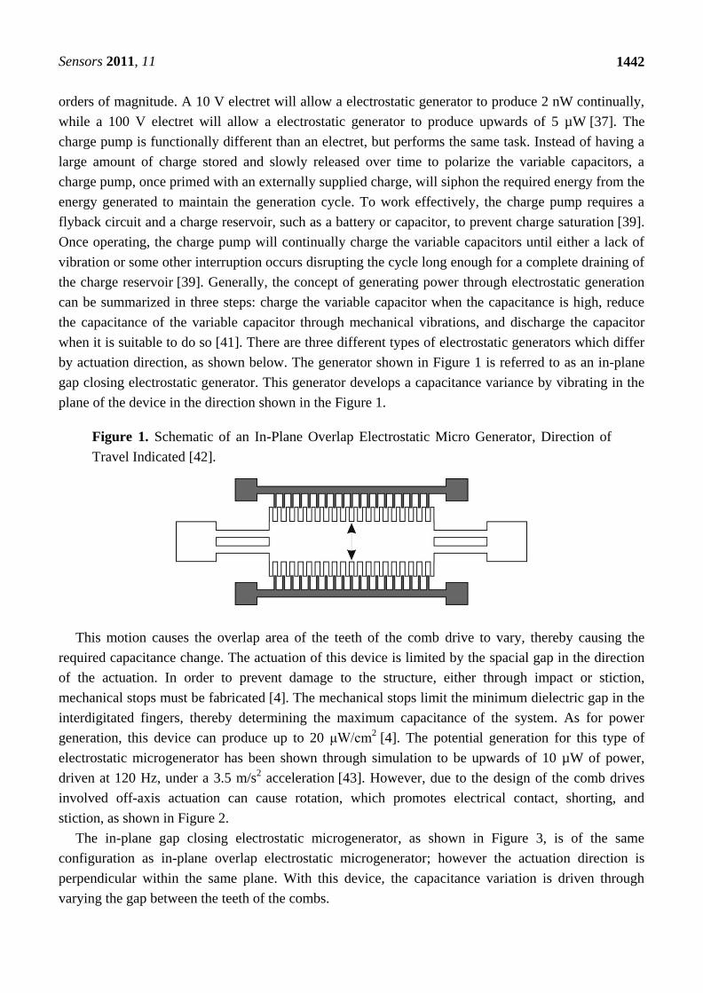
Figure 1. Schematic of an In-Plane Overlap Electrostatic Micro Generator, Direction of
Travel Indicated [42].
This motion causes the overlap area of the teeth of the comb drive to vary, thereby causing the
required capacitance change. The actuation of this device is limited by the spacial gap in the direction
of the actuation. In order to prevent damage to the structure, either through impact or stiction,
mechanical stops must be fabricated [4]. The mechanical stops limit the minimum dielectric gap in the
interdigitated fingers, thereby determining the maximum capacitance of the system. As for power
generation, this device can produce up to 20 μW/cm2 [4]. The potential generation for this type of
electrostatic microgenerator has been shown through simulation to be upwards of 10 µW of power,
driven at 120 Hz, under a 3.5 m/s2 acceleration [43]. However, due to the design of the comb drives
involved off-axis actuation can cause rotation, which promotes electrical contact, shorting, and
stiction, as shown in Figure 2.
The in-plane gap closing electrostatic microgenerator, as shown in Figure 3, is of the same
configuration as in-plane overlap electrostatic microgenerator; however the actuation direction is
perpendicular within the same plane. With this device, the capacitance variation is driven through
varying the gap between the teeth of the combs.
Sensors 2011, 11
1443
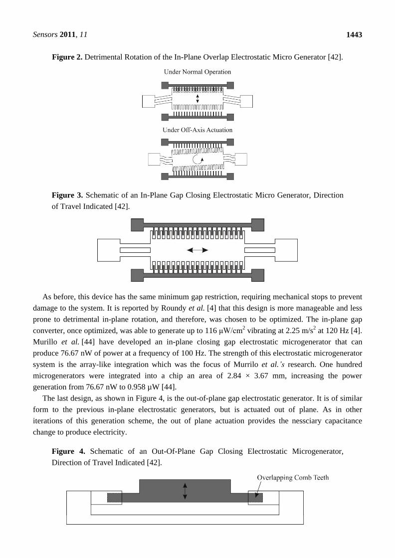
Figure 2. Detrimental Rotation of the In-Plane Overlap Electrostatic Micro Generator [42].
Figure 3. Schematic of an In-Plane Gap Closing Electrostatic Micro Generator, Direction
of Travel Indicated [42].
As before, this device has the same minimum gap restriction, requiring mechanical stops to prevent
damage to the system. It is reported by Roundy et al. [4] that this design is more manageable and less
prone to detrimental in-plane rotation, and therefore, was chosen to be optimized. The in-plane gap
converter, once optimized, was able to generate up to 116 μW/cm2 vibrating at 2.25 m/s
2 at 120 Hz [4].
Murillo et al. [44] have developed an in-plane closing gap electrostatic microgenerator that can
produce 76.67 nW of power at a frequency of 100 Hz. The strength of this electrostatic microgenerator
system is the array-like integration which was the focus of Murrilo et al.’s research. One hundred
microgenerators were integrated into a chip an area of 2.84 × 3.67 mm, increasing the power
generation from 76.67 nW to 0.958 µW [44].
The last design, as shown in Figure 4, is the out-of-plane gap electrostatic generator. It is of similar
form to the previous in-plane electrostatic generators, but is actuated out of plane. As in other
iterations of this generation scheme, the out of plane actuation provides the nessciary capacitance
change to produce electricity.
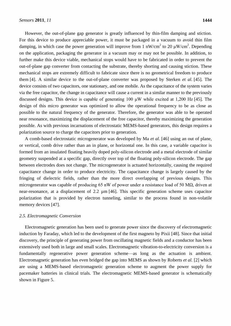
Figure 4. Schematic of an Out-Of-Plane Gap Closing Electrostatic Microgenerator,
Direction of Travel Indicated [42].
Sensors 2011, 11
1444
However, the out-of-plane gap generator is greatly influenced by thin-film damping and stiction.
For this device to produce appreciable power, it must be packaged in a vacuum to avoid thin film
damping, in which case the power generation will improve from 1 nW/cm2 to 20 μW/cm
2. Depending
on the application, packaging the generator in a vacuum may or may not be possible. In addition, to
further make this device viable, mechanical stops would have to be fabricated in order to prevent the
out-of-plane gap converter from contacting the substrate, thereby shorting and causing stiction. These
mechanical stops are extremely difficult to fabricate since there is no geometrical freedom to produce
them [4]. A similar device to the out-of-plane converter was proposed by Sterken et al. [45]. The
device consists of two capacitors, one stationary, and one mobile. As the capacitance of the system varies
via the free capacitor, the change in capacitance will cause a current in a similar manner to the previously
discussed designs. This device is capable of generating 100 μW while excited at 1,200 Hz [45]. The
design of this micro generator was optimized to allow the operational frequency to be as close as
possible to the natural frequency of the generator. Therefore, the generator was able to be operated
near resonance, maximizing the displacement of the free capacitor, thereby maximizing the generation
possible. As with previous incarnations of electrostatic MEMS-based generators, this design requires a
polarization source to charge the capacitors prior to generation.
A comb-based electrostatic microgenerator was developed by Ma et al. [46] using an out of plane,
or vertical, comb drive rather than an in plane, or horizontal one. In this case, a variable capacitor is
formed from an insulated floating heavily doped poly-silicon electrode and a metal electrode of similar
geometry suspended at a specific gap, directly over top of the floating poly-silicon electrode. The gap
between electrodes does not change. The microgenerator is actuated horizontally, causing the required
capacitance change in order to produce electricity. The capacitance change is largely caused by the
fringing of dielectric fields, rather than the more direct overlapping of previous designs. This
microgenerator was capable of producing 65 nW of power under a resistance load of 50 MΩ, driven at
near-resonance, at a displacement of 2.2 µm [46]. This specific generation scheme uses capacitor
polarization that is provided by electron tunneling, similar to the process found in non-volatile
memory devices [47].
2.5. Electromagnetic Conversion
Electromagnetic generation has been used to generate power since the discovery of electromagnetic
induction by Faraday, which led to the development of the first magneto by Pixii [48]. Since that initial
discovery, the principle of generating power from oscillating magnetic fields and a conductor has been
extensively used both in large and small scales. Electromagnetic vibration-to-electricity conversion is a
fundamentally regenerative power generation scheme—as long as the actuation is ambient.
Electromagnetic generation has even bridged the gap into MEMS as shown by Roberts et al. [2] which
are using a MEMS-based electromagnetic generation scheme to augment the power supply for
pacemaker batteries in clinical trials. The electromagnetic MEMS-based generator is schematically
shown in Figure 5.
Sensors 2011, 11
1445
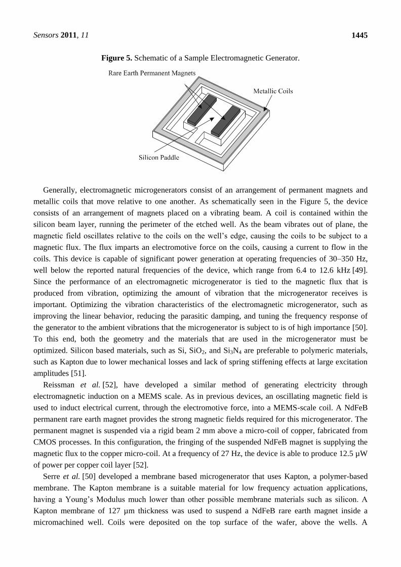
Figure 5. Schematic of a Sample Electromagnetic Generator.
Generally, electromagnetic microgenerators consist of an arrangement of permanent magnets and
metallic coils that move relative to one another. As schematically seen in the Figure 5, the device
consists of an arrangement of magnets placed on a vibrating beam. A coil is contained within the
silicon beam layer, running the perimeter of the etched well. As the beam vibrates out of plane, the
magnetic field oscillates relative to the coils on the well’s edge, causing the coils to be subject to a
magnetic flux. The flux imparts an electromotive force on the coils, causing a current to flow in the
coils. This device is capable of significant power generation at operating frequencies of 30–350 Hz,
well below the reported natural frequencies of the device, which range from 6.4 to 12.6 kHz [49].
Since the performance of an electromagnetic microgenerator is tied to the magnetic flux that is
produced from vibration, optimizing the amount of vibration that the microgenerator receives is
important. Optimizing the vibration characteristics of the electromagnetic microgenerator, such as
improving the linear behavior, reducing the parasitic damping, and tuning the frequency response of
the generator to the ambient vibrations that the microgenerator is subject to is of high importance [50].
To this end, both the geometry and the materials that are used in the microgenerator must be
optimized. Silicon based materials, such as Si, SiO2, and Si3N4 are preferable to polymeric materials,
such as Kapton due to lower mechanical losses and lack of spring stiffening effects at large excitation
amplitudes [51].
Reissman et al. [52], have developed a similar method of generating electricity through
electromagnetic induction on a MEMS scale. As in previous devices, an oscillating magnetic field is
used to induct electrical current, through the electromotive force, into a MEMS-scale coil. A NdFeB
permanent rare earth magnet provides the strong magnetic fields required for this microgenerator. The
permanent magnet is suspended via a rigid beam 2 mm above a micro-coil of copper, fabricated from
CMOS processes. In this configuration, the fringing of the suspended NdFeB magnet is supplying the
magnetic flux to the copper micro-coil. At a frequency of 27 Hz, the device is able to produce 12.5 µW
of power per copper coil layer [52].
Serre et al. [50] developed a membrane based microgenerator that uses Kapton, a polymer-based
membrane. The Kapton membrane is a suitable material for low frequency actuation applications,
having a Young’s Modulus much lower than other possible membrane materials such as silicon. A
Kapton membrane of 127 µm thickness was used to suspend a NdFeB rare earth magnet inside a
micromachined well. Coils were deposited on the top surface of the wafer, above the wells. A
Sensors 2011, 11
1446
prototype microgenerator, with a 7 × 7 × 4 mm3 magnet and a 13 × 13 mm
2 Kapton membrane with a
resonant frequency of 360 Hz was able to produce a peak power of 45 nW [50]. An optimization of
this generator was undertaken in order to increase the power output [51]. The geometry of the Kapton
membrane was optimized to provide greater displacement to the permanent magnet, in order to
maximize the magnetic flux that would be produced. Unfortunately, parasitic damping, caused by
spring stiffening effects increases as the amplitude of the membrane displacement increases, adding
losses to the system with increased displacement. To further increase the power generation that this
type of microgenerator can produce, thicker electroplated copper coils have been suggested by
Serre et al. to increase the peak power generation from 45 nW to between 60 to 120 μW [51].
A rotary electromagnetic generator was produced by Pan et al. [53]. The microgenerator consists of
two disks, one disc consisting of an 8-pole NdFeB magnet, and the other consisting of various layers of
copper multipolar coils with a line width of 30 µm. These two discs were separated by one millimeter -
the magnetic disc suspended on a rotary mechanism, while the coils attached to a static platform. In
this case, four layers of copper coils were used to increase the generation potential of the rotary
electromagnetic generator. Running the rotating platform at 150 Hz, the maximum induced voltage
from a four layer coil disc is 111.2 mV, with a maximum power output of 386.42 µW. Another rotary
generator was developed by Herrault et al. [54] that uses an air turbine as an actuation mechanism for
its rotary microgenerator. As with other electromagnetic microgenerators, a NdFeB permanent magnet
will be used to provide the strong magnetic field required. The design of the microgenerator in this
case is similar to Pan et al. [53], however the stator coils are of a more complex design. Coils that will
experience the same electrical phase are connected, thereby increasing the electricity generated at a
specific electrical phase to be maximized. The poles of the coil assembly were equally spaced,
depending upon the number of coils that were used in the stator design. In addition, to maximize the
generated electric power with small diameter rotary microgenerators the speed at which the rotor will
rotate increases, in comparison to macro scale devices. This device is driven at 392 kRPM,
producing 6.6 mW of electrical power. These microgenerators produce a fair amount of electricity;
however rotation is not a convenient motion of vibration to harvest energy from. To provide the
necessary mechanical rotation for most electromagnetic generation schemes a MEMS-based turbine or
rotational engine will be required.
2.6. Piezoelectric Conversion
Piezoelectric generation is a well researched method of harvesting power from mechanical
vibrations. When the crystal structure of the piezoelectric material is loaded, the micro-structure of the
crystal is distorted. In order to maintain electrical equilibrium within the crystal the electrons become
mobile and shift, creating a current. This is referred to as the direct piezoelectric effect. Alternatively,
the exact opposite phenomenon, the converse piezoelectric effect, can also take place. For
micro-generation, the direct piezoelectric effect is used to convert vibration to electricity. The direct
piezoelectric effect is used for microgeneration and sensing purposed, while the converse piezoelectric
effect is used mainly for actuation. Piezoelectric generation is frequency dependant, maximized as the
frequency at which the system is driven is at resonance [55], where the displacement is maximized.
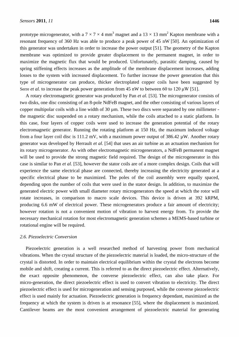
Cantilever beams are the most convenient arrangement of piezoelectric material for generating
Sensors 2011, 11
1447
purposes because it allows for the 31-mode of the piezoelectric material to be accessed easily,
maximizing the voltage output of the piezoelectric material, especially in low strain realms [56], as
shown below in Figure 6 [55].
Figure 6. Schematic of a Laminated Piezoelectric Beam Micro Generator [55].
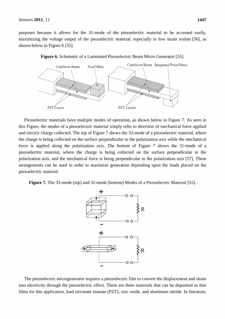
Piezoelectric materials have multiple modes of operation, as shown below in Figure 7. As seen in
this Figure, the modes of a piezoelectric material simply refer to direction of mechanical force applied
and electric charge collected. The top of Figure 7 shows the 33-mode of a piezoelectric material, where
the charge is being collected on the surface perpendicular to the polarization axis while the mechanical
force is applied along the polarization axis. The bottom of Figure 7 shows the 31-mode of a
piezoelectric material, where the charge is being collected on the surface perpendicular to the
polarization axis, and the mechanical force is being perpendicular to the polarization axis [57]. These
arrangements can be used in order to maximize generation depending upon the loads placed on the
piezoelectric material.
Figure 7. The 33-mode (top) and 31-mode (bottom) Modes of a Piezoelectric Material [55].
The piezoelectric microgenerator requires a piezoelectric film to convert the displacement and strain
into electricity through the piezoelectric effect. There are three materials that can be deposited as thin
films for this application, lead zirconate titanate (PZT), zinc oxide, and aluminum nitride. In literature,
Sensors 2011, 11
1448
PZT is the dominantly used for power generation purposes. ZnO and AlN are more commonly used in
actuation and sensing. In terms of microfabrication, ZnO and AlN are less complicated and have fewer
equipment contamination issues than PZT. The material properties of these thin films are
shown below:
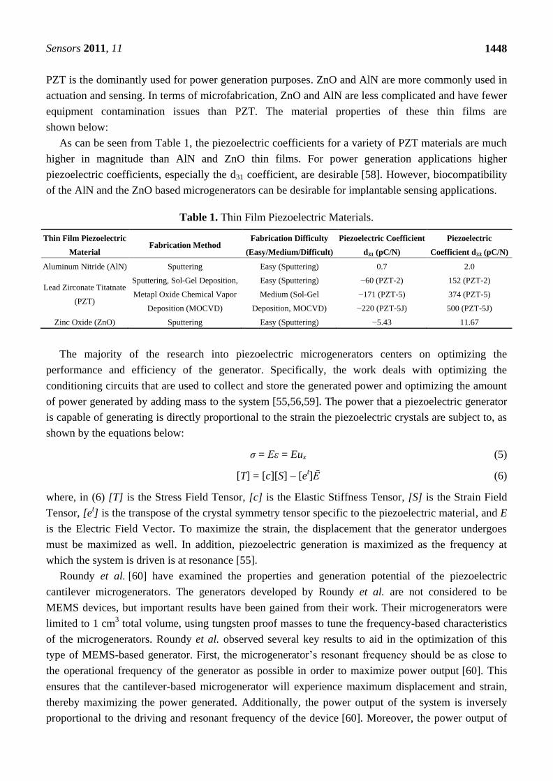
As can be seen from Table 1, the piezoelectric coefficients for a variety of PZT materials are much
higher in magnitude than AlN and ZnO thin films. For power generation applications higher
piezoelectric coefficients, especially the d31 coefficient, are desirable [58]. However, biocompatibility
of the AlN and the ZnO based microgenerators can be desirable for implantable sensing applications.
Table 1. Thin Film Piezoelectric Materials.
Thin Film Piezoelectric
Material Fabrication Method
Fabrication Difficulty
(Easy/Medium/Difficult)
Piezoelectric Coefficient
d31 (pC/N)
Piezoelectric
Coefficient d33 (pC/N)
Aluminum Nitride (AlN) Sputtering Easy (Sputtering) 0.7 2.0
Lead Zirconate Titatnate
(PZT)
Sputtering, Sol-Gel Deposition,
Metapl Oxide Chemical Vapor
Deposition (MOCVD)
Easy (Sputtering)
Medium (Sol-Gel
Deposition, MOCVD)
−60 (PZT-2)
−171 (PZT-5)
−220 (PZT-5J)
152 (PZT-2)
374 (PZT-5)
500 (PZT-5J)
Zinc Oxide (ZnO) Sputtering Easy (Sputtering) −5.43 11.67
The majority of the research into piezoelectric microgenerators centers on optimizing the
performance and efficiency of the generator. Specifically, the work deals with optimizing the
conditioning circuits that are used to collect and store the generated power and optimizing the amount
of power generated by adding mass to the system [55,56,59]. The power that a piezoelectric generator
is capable of generating is directly proportional to the strain the piezoelectric crystals are subject to, as
shown by the equations below:
σ = Eε = Eux (5)
[T] = [c][S] – [et]Ē (6)
where, in (6) [T] is the Stress Field Tensor, [c] is the Elastic Stiffness Tensor, [S] is the Strain Field
Tensor, [et] is the transpose of the crystal symmetry tensor specific to the piezoelectric material, and E
is the Electric Field Vector. To maximize the strain, the displacement that the generator undergoes
must be maximized as well. In addition, piezoelectric generation is maximized as the frequency at
which the system is driven is at resonance [55].
Roundy et al. [60] have examined the properties and generation potential of the piezoelectric
cantilever microgenerators. The generators developed by Roundy et al. are not considered to be
MEMS devices, but important results have been gained from their work. Their microgenerators were
limited to 1 cm3 total volume, using tungsten proof masses to tune the frequency-based characteristics
of the microgenerators. Roundy et al. observed several key results to aid in the optimization of this
type of MEMS-based generator. First, the microgenerator’s resonant frequency should be as close to
the operational frequency of the generator as possible in order to maximize power output [60]. This
ensures that the cantilever-based microgenerator will experience maximum displacement and strain,
thereby maximizing the power generated. Additionally, the power output of the system is inversely
proportional to the driving and resonant frequency of the device [60]. Moreover, the power output of
Sensors 2011, 11
1449
the microgenerator is proportional to the seismic mass of the system. Higher mass in the system helps
reduce the natural frequency of the microgenerator. Furthermore, Roundy et al. also determined that
the energy removed from the generator will act as mechanical damping to the system, due to the
piezoelectric coupling in the system [60]. The opposite is also possible; increasing the electrically
induced damping to the system will maximize the power output. Roundy et al. were able to produce
cantilever-based piezoelectric microgenerators that were able to produce 375 μW from driving
vibrations of 2.5 m/s2 at 120 Hz [60].
Aluminum nitride based cantilever systems are also being explored for piezoelectric
microgeneration applications. As discussed by Elfrink et al. [61], the major advantage of using
AlN-based piezoelectric microgeneration scheme, in comparison to a PZT-based one, is the higher
optimum load resistance of the AlN in comparison to the PZT. With an optimum load resistance, the
generator will produce the optimum power. For AlN, Elfrink reported an optimum load resistance
of 0.1–1.0 MΩ, where PZT based microgenerators generally have optimum load resistances of a few
kΩ. This difference in load resistance causes AlN to generally have higher output voltages that PZT
(for equivalent power output), which may be desirable for certain power generation applications. The
AlN-based cantilever generators are fairly large for MEMS-based generation, up to 7 × 7 mm in
footprint, with beam thicknesses of approximately 45 µm, which allowed for natural beam frequencies
as low as 277 Hz. The maximum power output from this scheme was 60 µW at an operational/natural
frequency of 572 Hz. To be efficient, this microgenerator needs to be packaged in a vacuum, since air
damping in the required encapsulation scheme causes significant damping and generation losses.
In addition to the cantilever type piezoelectric microgenerator, membrane-based generators are
being investigated for both implantable and ambient uses. Generally, a circular membrane of lead
zirconate titanate (PZT) is used [62] due to its axisymmetry. In biomedical applications, a circular
membrane piezoelectric microgenerator can be tuned to actuate from pressure differences found in the
body, such as those generated by breathing, muscle contractions or blood flow. A circular piezoelectric
microgenerator [62] was designed to be actuated from the pressure difference (40 mmHg) that is
produced from a typical human pulse. This device was able to generate 61 µW experimentally from
the 40 mmHg pressure load. Ramsay and Clark [56] have also examined using blood pressure as a
power source for piezoelectric membrane microgenerators. It has been reported that the power
available from variations in blood pressure is as high as 0.373 W [63]. Even with the relatively low
conversion efficiency of 34% of the PZT-5A material used in the analysis, it is theoretically possible to
produce membrane-based piezoelectric microgenerators that could easily provide 10 mW of
continuous power. However, Ramsay and Clark discovered that although the generation potential was
there, the size of the membrane would be a limiting factor in generation. With membranes limited
to 1 cm2 it was not possible to produce 10 mW of continuous power. Using blood pressure (40 mmHg)
alone as an actuation method for the piezoelectric microgenerator, and limiting the size of the
membrane in the microgenerator to 1 cm2, it was possible to continuously supply microwatts of
continuous power, while being able to provide milliwatts range power intermittently when the
displacement of the microgenerator is maximum.
In addition to piezoelectric membranes for biomedical applications, a PZT microfiber generator has
been developed by Ishisaka et al. [64] in which the contractions of a heart muscle are used to actuate
the piezoelectric microfiber generator. The piezoelectric microfibers are fabricated by depositing PZT
Sensors 2011, 11
1450
onto a platinum wire, and then plating the wire with nickel in order to complete the electrical circuit. A
PDMS membrane is then placed between the fiber and the heart muscle to provide biocompatibility.
As the heart muscle contracts, the PDMS membrane is deflected, which in turn causes the embedded
PZT microfiber to deflect as well. In experiments, cultured cardiomyocytes were used for actuation.
These lab-grown cells actuated the piezoelectric generator at a frequency of 1.1 Hz, producing
between 40–80 mV, for a single ~100 µm fiber. The strength of this microgenerator is the high
biocompatibility of the PDMS membrane encapsulation that prevents contact between the PZT and the
cardiomyocytes. Not only is the material highly flexible, allowing for actuation, it is completely
biocompatible. Arrays of PZT microfibers may be used to increase generation in this application.
Another fiber-based piezoelectric vibration scheme uses Zinc Oxide nanowires to generate
electricity on a micro scale. The ZnO nanowires are grown using a wet chemistry method to deposit
the nanowires on a plastic substrate [65]. The wet chemistry method can be altered for different
orientations and densities of ZnO nanowires. The flexibility of the plastic substrate allows for the ZnO
nanowires to be used in a flexible application, such as implantable biosensors [65]. The flexibility will
allow for the substrate to flex with muscles and tissues, since in this case, this is generally an
area-based method of generation. ZnO wires with a 300 nm diameter, 1 µm long, can produce an
output power of approximately 5 pW at 45mV, under a 5 nN contact force load through AFM
actuation [65]. Xu et al. [66] have developed ZnO nanowire-based array microgenerators deposited on
Kapton, using a similar process as above. The deposited ZnO nanowire array is then encapsulated by a
soft polymer, such as photoresist in order to protect the nanowires from the environment. This
generator was capable of generating 1.26 V at a strain of 0.19%, potentially being capable of charging
a AA battery [66], producing a peak power output of 2.7 mW/cm3. A similar microgenerator has been
used in clinical trials by Li et al. [67] to generate power using a ZnO nanowire generator in an in vivo
application. This microgenerator has bigger nanowires than the previous two microgenerators having a
diameter of 100–800 nm and length of 100–500 µm [67], packaged in a similar manner using flexible
polymer materials as above. The microgenerator was implanted on the diaphragm muscle and heart of
live rats in order to test the potential of this type of microgenerator in an implantable application. For
the expansion and contraction of the diaphragm during breathing, the ZnO nanowire generator was
able to generate 1 mV at 1 pA [67]. The generator was able to generate more power from the heart beat
of the rat, generating 3 mV and 30 pA [67]. Although this experiment produced significantly less
power than the previous studies that used purely mechanical stimulation, it is an important first step for
ZnO nanowire-based in vivo microgenerators.
3. Discussion
For implantable biosensing power systems applications, there are a variety of possible generation
techniques that could allow existing power systems to be supplemented or replaced, allowing for long
term and autonomous operation. Energy scavenging techniques are generally more suitable for this
type of operation, since no additional fuels or stimuli would be needed for continuous power
generation. In addition, with suitable use of sleep modes, power conditioning circuits, and power
storage through thin film batteries or capacitors, an entirely self contained power system could be
easily integrated into wireless implantable biosensing platforms. Not only would this allow for
Sensors 2011, 11
1451
increased operational time, additional components could be added to the implantable system, allowing
for increased functionality, without adversely affecting the total lifespan of the implant.
In addition to being regenerative, the MEMS-based microgenerators must also be biocompatible for
implantation. Either all components must be suitable for implantation, or sufficient packaging must be
in place to prevent possible biocompatibility issues. This is usually accomplished by packaging the
microgenerators or biosensing platform in polymeric or silicone gel encapsulation [68]. This type of
packaging is required to ensure biocompatibility both for the patient and the implant. The patient must
be protected from possible cytotoxic materials, while the implant itself must be protected from
environmental factors in vivo that may reduce their generation effectiveness. The majority of materials
used in MEMS devices, including silicon, silicon oxide, polysilicon, silicon nitride, titanium, and some
photoresists, such as SU-8, have been proven to be non-cytotoxic [68]. However, there are some
materials, such as lead zirconate titanate (PZT) that can be cytotoxic if improperly packaged. In
addition, the topology of various MEMS devices may cause many sharp edges to be present on the
cellular level, allowing for the potential of localized cell damage through direct contact. For these
reasons, MEMS devices used in implantable biosensing are usually packaged in a biocompatible
manner, regardless of the cytotoxicity of the materials involved.
The type of MEMS-based generator chosen for a specific implantable application depends solely on
the type of input energy that is available in the specific implantation site. Ambient light, the most
plentiful source of input energy available, suffers from major issues with light intensity. For example,
the efficiency of a photoelectric generator suffers greatly from diminished light intensity, up to a 94%
loss in efficiency from not being in direct sunlight [4]. For implantable systems, this could be
troublesome, since light does not penetrate very deeply subcutaneously; therefore the efficiency of the
photoelectric based systems would be additionally diminished for implantable systems. Ambient heat
generated by the body is also an abundant energy source for implantable systems. The body constantly
generates heat from the various biological processes required to sustain life. To maximize efficiencies,
the areas of the body with maximum temperature differentials should be prioritized, for example,
where blood vessels are in close proximity to the exterior of the body such as the neck, wrists, and
ankles. Ambient vibration in the body can be any movement, voluntary or involuntary within the body.
This can range from the displacements from a beating heart, expanding diaphragm, a pulse from an
artery, or shock/movement from walking. Each of these vibrations can be harvested by a variety of
generation schemes as long as careful design allows for the capture of these motions. This may involve
specific tuning of the microgenerator to a specific actuation frequency range through design or active
stiffening control. In addition, arrays of vibration driven microgenerators may be arranged to capture a
wide frequency band of actuation, each microgenerator in the array tuned to a specific subsection of
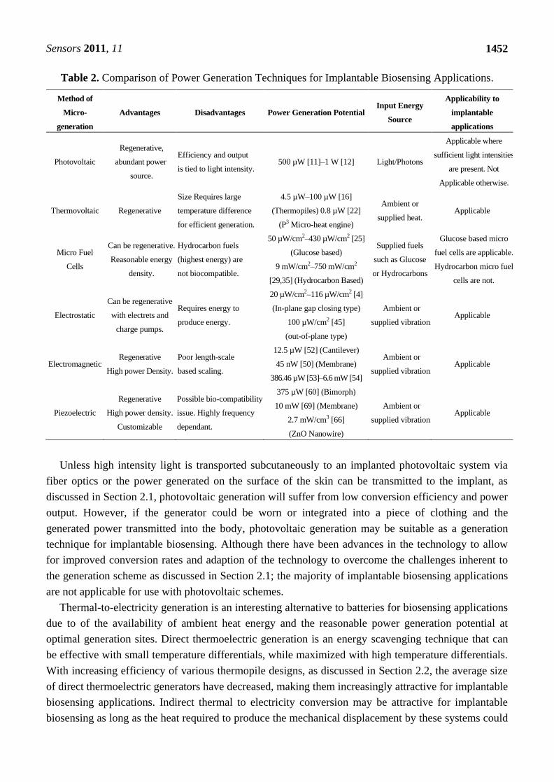
that frequency band. Table 2 briefly states the advantages, disadvantages, and power generation
potential of each type of power generation explored. As shown in the Table, photovoltaic schemes are
perhaps the least suitable for implantable biosensing applications. The requirement for direct light for
optimum generation makes the photovoltaic class of microgenerators somewhat impractical for
implantable biosensing applications.
Sensors 2011, 11
1452
Table 2. Comparison of Power Generation Techniques for Implantable Biosensing Applications.
Method of
Micro-
generation
Advantages Disadvantages Power Generation Potential Input Energy
Source
Applicability to
implantable
applications
Photovoltaic
Regenerative,
abundant power
source.
Efficiency and output
is tied to light intensity. 500 µW [11]–1 W [12] Light/Photons
Applicable where
sufficient light intensities
are present. Not
Applicable otherwise.
Thermovoltaic Regenerative
Size Requires large
temperature difference
for efficient generation.
4.5 µW–100 µW [16]
(Thermopiles) 0.8 µW [22]
(P3 Micro-heat engine)
Ambient or
supplied heat. Applicable
Micro Fuel
Cells
Can be regenerative.
Reasonable energy
density.
Hydrocarbon fuels
(highest energy) are
not biocompatible.
50 µW/cm2–430 µW/cm2 [25]
(Glucose based)
9 mW/cm2–750 mW/cm2
[29,35] (Hydrocarbon Based)
Supplied fuels
such as Glucose
or Hydrocarbons
Glucose based micro
fuel cells are applicable.
Hydrocarbon micro fuel
cells are not.
Electrostatic
Can be regenerative
with electrets and
charge pumps.
Requires energy to
produce energy.
20 µW/cm2–116 µW/cm2 [4]
(In-plane gap closing type)
100 µW/cm2 [45]
(out-of-plane type)
Ambient or
supplied vibration. Applicable
Electromagnetic Regenerative
High power Density.
Poor length-scale
based scaling.
12.5 µW [52] (Cantilever)
45 nW [50] (Membrane)
386.46 µW [53]–6.6 mW [54]
Ambient or
supplied vibration. Applicable
Piezoelectric
Regenerative
High power density.
Customizable
Possible bio-compatibility
issue. Highly frequency
dependant.
375 µW [60] (Bimorph)
10 mW [69] (Membrane)
2.7 mW/cm3 [66]
(ZnO Nanowire)
Ambient or
supplied vibration. Applicable
Unless high intensity light is transported subcutaneously to an implanted photovoltaic system via
fiber optics or the power generated on the surface of the skin can be transmitted to the implant, as
discussed in Section 2.1, photovoltaic generation will suffer from low conversion efficiency and power
output. However, if the generator could be worn or integrated into a piece of clothing and the
generated power transmitted into the body, photovoltaic generation may be suitable as a generation
technique for implantable biosensing. Although there have been advances in the technology to allow
for improved conversion rates and adaption of the technology to overcome the challenges inherent to
the generation scheme as discussed in Section 2.1; the majority of implantable biosensing applications
are not applicable for use with photovoltaic schemes.
Thermal-to-electricity generation is an interesting alternative to batteries for biosensing applications
due to of the availability of ambient heat energy and the reasonable power generation potential at
optimal generation sites. Direct thermoelectric generation is an energy scavenging technique that can
be effective with small temperature differentials, while maximized with high temperature differentials.
With increasing efficiency of various thermopile designs, as discussed in Section 2.2, the average size
of direct thermoelectric generators have decreased, making them increasingly attractive for implantable
biosensing applications. Indirect thermal to electricity conversion may be attractive for implantable
biosensing as long as the heat required to produce the mechanical displacement by these systems could
Sensors 2011, 11
1453
be gained from methods other than combustion. Combustion, in vivo, could have significant packaging
challenges such as reactant and product handling challenges, not to mention the localized heating.
Keeping this in mind, the methods discussed in Section 2.2 using combustion as a heat source may not
be directly applicable to implantable biosensing applications. In addition, the implantation location of
the thermoelectric-based microgenerators is of great importance, since the body has an inhomogeneous
thermal profile. The possible applications of thermoelectric generation may be limited by the thermal
profile of the body at the required implantation site. Locations within reasonable proximity of major
blood vessels may be the most suitable for implantable biosensing, since blood itself plays a major role
in thermal regulation within the body. Without a sufficient thermal gradient at the implantation site, it
may not be feasible to use thermoelectric generation to produce sufficient operational power in
implantable biosensing applications.
Micro fuel cells are a suitable power generation scheme for implantable biosensing as long as the
fuel cell is regenerative and biocompatible. Regenerative fuel cells, such as glucose based fuel cells,
can be implanted for long term operation since the fuel and oxidation reagent is replenished constantly
through the electrochemical reactions that generate power. In addition, glucose is readily available in
the body, thus additional fuel for glucose-based micro fuel cells is available if needed. As discussed in
Section 2.3, micro fuel cells using non-biocompatible reactants generally produce more power than
those using biocompatible fuels. There are intrinsic difficulties when dealing with non-biocompatible
reactants and implantation, such as the possibility of insufficient packaging causing the potential
leaching of reactants out of the fuel cell damaging surrounding tissues. However, the advances in
miniaturization, components, composition, and packaging discussed in Section 2.3 may eventually lead
to a higher output biocompatible fuel cell utilizing non-biocompatible fuels. The smaller and more
efficient a micro fuel cell, the more applicable it will be to implantable applications. Micro fuel cells
are the only location independent MEMS-based generation technique, not relying on a specific
implantation location or physical phenomenon to supply the specific input energy required to produce
power. As long as the implantation location can accommodate the size of the micro fuel cell and does
not impart any specific loading to the micro fuel cell that may damage its packaging, it would be
applicable for implantable biosensing techniques.
Electrostatic MEMS-based generation requires very specific physical motions in order to produce
an optimum amount of electricity. Implantation locations that undergo predictable planar
displacements or vibrations are ideal for electrostatic generation. A specific method of electrostatic
generation, as discussed in detail in Section 2.4, can be chosen in order to maximize the generation
attained from a specific known planar actuation. The strength of electrostatic MEMS-based generation
lies within the multiple actuation directions and arrangements that are possible. This is important for
biosensing applications, since conceivably, electrostatic generation could be used in a multitude of
orientations, many of which would not be possible with other vibration-based generation schemes.
However, rotation and off axis motion is troublesome for electrostatic based schemes, causing
potential damage through collision and stiction. In addition, in order to generate power, the
electrostatic generator must be pre-charged in order to take full advantage of the motion-induced
capacitance changes. Efficiency and generation of these systems are improved by using self-charging
mechanisms such as electrets and charge pumps, as discussed in Section 2.4. Using these self-charging
mechanisms, the electrostatic MEMS-based microgenerators are a self-contained system suitable for a
Sensors 2011, 11
1454
multitude of implantable biosensing applications where known planar motions and vibrations
are present.
Electromagnetic generation is an energy scavenging technique that is currently used in some high
profile implantable applications, such as generating supplementary power for pacemaker batteries [2].
As with electrostatic-based generation, electromagnetic generation has a directional actuation
dependence, therefore knowledge of the implantation site conditions is critical. However,
electromagnetic generation is significantly more robust than electrostatic, since any out of plane
actuation is usable—off axis actuation is not detrimental or damaging to the electromagnetic generator.
As discussed in Section 2.5, optimization of the power generated through this strategy is achieved by
maximizing the magnetic flux experienced by the coils of the generator. Rotary electromagnetic
generation is a well known method to maximize the magnetic flux possible on a macro-scale. Although
a novel MEMS application and relatively high power density scheme, rotary motion may be difficult to
supply to the microgenerator in comparison to linear actuation. Rotary MEMS engines may be used to
accomplish this, although their applicability in vivo would be significantly limited. Therefore, linearly
actuated electromagnetic MEMS-based microgeneration techniques would have more possible
implantable applications than rotary ones. Electromagnetic generation, although having reasonable
power densities, can have scaling issues with miniaturization. As the scale of the electromagnetic
generators decreases, it has been suggested by Beeby et al. [70] that the power generation potential of
the microgenerator decreases as well. The power density and power generation of electromagnetic
based schemes can lag behind other similar techniques in this size regime.
Piezoelectric based generation is suitable for implantable biosensing having high power densities
allowing for sufficient power generation for many applications. For high power density piezoelectric
MEMS-based generation using PZT films, the major challenge in regards to implantable applications
is biocompatibility. As discussed in Section 2.6, advancements toward biocompatible PZT-based
piezoelectric generators have been made. Biocompatible packaging, such as PDMS will be required in
order to allow piezoelectric schemes to be used in implantable biosensing applications. Although AlN
and ZnO-based microgenerators have less power generation potential according to the material
properties of the respective piezoelectric films, important advances have been made towards using
microgenerators based on these materials in in-vivo applications. The recent advances and inherent
biocompatibility of these materials is making AlN and ZnO-based piezoelectric generators an
interesting alternative to PZT-based systems for implantable applications. As with electromagnetic
generation, off-axis actuation is not potentially dangerous to the operation of the microgenerator. It is
non-optimal, but will not prevent generation or cause damage. As discussed in Section 2.6,
optimization of the frequency response is required in order to maximize the power generated. The
vibrations that actuate the piezoelectric microgenerators can be low frequency and low amplitude,
which are easily achievable for implantable biosensing. The piezoelectric microgenerators can be
tuned to specific frequency responses found at the implantation site, allowing the microgenerators to
be designed to maximize the local power generation possible at an implantation site. In addition, being
able to take advantage of pressure variations and displacements, such as an arterial pulse or a flexing
muscle is attractive for biosensing applications.
Sensors 2011, 11
1455
4. Conclusions
There are many alternatives available to augment or replace existing conventional battery-based
systems for powering implantable biosensors. These systems include photovoltaic, thermovoltaic, micro
fuel cells, electrostatic, electromagnetic, and piezoelectric based microgenerators. For implantable
biosensing applications the most suitable microgenerators are based on energy scavenging, using
ambient energy sources such as heat and vibration to produce electricity. In addition, the microgenerator
must be able to easily operate as a surgical implant and must be completely biocompatible. Therefore,
micro-generation schemes based upon photovoltaic microgenerators and hydrocarbon-based micro fuel
cells may not be suitable for microgeneration in implantable biosensing applications.
Determining the correct microgeneration scheme for a specific implantable biosensing application
can be a difficult task. Power density is important for implantable biosensing power generation. The
smaller a microgenerator can be in this case, the less invasive the implant. Therefore, microgenerators
with high power densities, for example, those using piezoelectric and electromagnetic schemes would
be the least invasive for a vibration-based application, requiring the smallest volume to provide a
necessary power level. In situations where more than one generation physics can be utilized, power
density should be a major consideration in order to reduce the power system’s overall size.
The most significant factor used in determining the most applicable microgeneration technique to
use in a specific implantable biosensing application is ambient energy available at the implantation
site. Whether the energy available is solar energy, heat, or vibration, the microgeneration technologies
studied are exclusive in terms of their input energy. If the implantation site is near the surface of the
skin, it may be advantageous to consider photovoltaic schemes. If high thermal gradients are present at
an implantation site, thermovoltaic schemes will outperform the other available technologies. In areas
of high motion and vibration, the vibration-based energy harvesting techniques, such as electrostatic,
electromagnetic, and piezoelectric schemes will be the optimum choice. For example, if no harvestable
energy is present at a specific implantation location, it will be more advantageous to focus on micro
fuel cell technologies than other alternatives. A well developed understanding of the specific input
energies available at an implantation site will lead to the best possible choice of a generation
technology for the specific in vivo application.
Acknowledgements
The financial support of the Natural Sciences and Engineering Research Council (NSERC) of
Canada and the Micro Systems Technology Research Initiative (MSTRI) through operating grants to
W. Moussa is gratefully acknowledged.
References and Notes
1. Schroeppel, E.; Lin, J. Reliability and Clinical Assessment of Pacemaker Power Sources. In
Handbook of Solid State Batteries & Capacitors, 2 ed.; Munshi, M.Z.A., Ed.; World Scientific
Publishing Co.: London, UK, 1999.
2. Roberts, P.; Stanley, G.; Morgan, J.M. Abstract 2165: Harvesting the Energy of Cardiac Motion
to Power a Pacemaker. Circulation 2008, 118, S_679-c-680.
Sensors 2011, 11
1456
3. Lee, J.B.; Chen, Z.Z.; Allen, M.G.; Rohatgi, A.; Arya, R. A Miniaturized High-Voltage Solar-Cell
Array as an Electrostatic Mems Power-Supply. J. Microelectromech. Syst. 1995, 4, 102-108.
4. Roundy, S.; Wright, P.K.; Pister, K.S.J. Micro-Electrostatic Vibration-to-Electricity Converters.
In Proceedings of the ASME International Mechanical Engineering Congress and Exposition,
New Orleans, LA, USA, November 2002.
5. Cantatore, E.; Ouwerkerk, M. Energy Scavenging and Power Management in Networks of
Autonomous Microsensors. Microelectron. J. 2006, 37, 1584-1590.
6. Ichiki, M.; Furue, H.; Kobayashi, T.; Morikawa, Y.; Nonaka, K.; Maeda, R. Photovoltaic
Properties of Ferroelectrics and its Applications to Optical Sensor. Proc. SPIE 2008,
doi: 10.1117/12.760416.
7. Barnett, A.M.; Domian, F.A.; Feycock, B.W.; Ford, D.H.; Kendall, C.L.; Rand, J.A.;
Ruffins, T.R.; Rock, M.L.; Hall, R.B. Development of Large Area Thin Crystalline Silicon-Film
Solar Cells. In Proceedings of Photovoltaic Specialists Conference, 1988., Conference Record of
the Twentieth IEEE, Las Vegas, NV, USA, September 1988; pp. 1569-1574.
8. Giles, C.R.; Dentai, A.; Burrus, C.A.; Kohutich, L.; Centanni, J. Microwatt-power InGaAs
Photogenerator for Lightwave Networks. IEEE Photonics Technol. Lett. 1997, 9, 666-668.
9. Dentai, A.G.; Burrows, E.C.; Giles, C.R.; Burrus, C.A.; Centanni, J.C. High-Voltage (2.1 V)
Integrated InGaAs Photogenerator. Electron. Lett. 1997, 33, 718-719.
10. Wojtczuk, S.; Parodos, T.; Walker, G. P/N In(Al) GaAs Multijunction Laser Power Converters. In
Proceedings of the 13th Space Photovoltaic Research and Technology Conference (SPRAT 13),
Cleveland, OH, USA, June 1994; pp. 363-363.
11. Dentai, A.G.; Giles, C.R.; Burrows, E.; Burrus, C.A.; Stulz, L.; Centanni, J.; Hoffman, J.;
Moyer, B. A Long-Wavelength 10-V Optical-to-Electrical InGaAs Photogenerator. IEEE
Photonics Technol. Lett. 1999, 11, 114-116.
12. Peña, R. Photovoltaic Converters for Optical Fibre-Based Power-by-Light Systems. Ph.D. Thesis,
Universidad Politecnica de Madrid: Madrid, Spain, 2004.
13. Lam, K.B.; Johnson, E.A.; Chiao, M.; Lin, L.W. A MEMS Photosynthetic Electrochemical Cell
Powered by Subcellular Plant Photosystems. J. Microelectromech. Syst. 2006, 15, 1243-1250.
14. Huesgen, T.; Woias, P.; Kockmann, N. Design and Fabrication of MEMS Thermoelectric
Generators with High Temperature Efficiency. Sens. Actuat. A Phys. 2008, 145-146, 423-429.
15. Kockmann, N.; Huesgen, T.; Woias, P. Microstructured in-Plane Thermoelectric Generators with
Optimized Heat Path. In Proceedings of International Solid-State Sensors, Actuators and
Microsystems Conference, 2007. TRANSDUCERS 2007, Lyon, France, June 2007; pp. 133-136.
16. Paradiso, J.A.; Starner, T. Energy Scavenging for Mobile and Wireless Electronics. IEEE
Pervasive Comput. 2005, 4, 18-27.
17. Stevens, J. Optimized Thermal Design of Small DT Thermoelectric Generator. In Proceedings of
34th Intersociety Energy Conversion Engineering Congress of the Soiciety of Automotive
Engineers, Vancouver , Canda, August 1999.
18. Leonov, V.; Fiorini, P.; Sedky, S.; Torfs, T.; van Hoof, C. Thermoelectric MEMS Generators as a
Power Supply for a Body Area Network. In Proceedings of The 13th International Conference on
Solid-State Sensors, Actuators and Microsystems, 2005. Digest of Technical Papers.
TRANSDUCERS ’05, Seoul, Korea, June 2005; pp. 291-294.
Sensors 2011, 11
1457
19. Tecpoyotl-Torres, M.; Varona, J.; Hamoui, A.A.; Escobedo-Alatorre, J.; Sanchez-Mondragon, J.
Polysilicon Thermal Micro-Actuators for Heat Scavenging and Power Conversion. Proc. SPIE
2008, doi: 10.1117/12.795768.
20. Mehra, A.; Zhang, X.; Ayon, A.A.; Waitz, I.A.; Schmidt, M.A.; Spadaccini, C.M. Six-Wafer
Combustion System for a Silicon Micro Gas Turbine Engine. J. Microelectromech. Syst. 2000, 9,
517-527.
21. Fu, K.; Knobloch, A.J.; Martinez, F.C.; Walther, D.C.; Fernandez-Pello, C.; Pisano, A.P.;
Liepmann, D. Design and Fabrication of a Silicon-Based MEMS Rotary Engine. In Proceedings
of the ASME International Mechanical Engineering Congress and Exposition, New York, NY,
USA, November 2001; pp. 875-880.
22. Whalen, S.; Thompson, M.; Bahr, D.; Richards, C.; Richards, R. Design, Fabrication and Testing
of the P3 Micro Heat Engine. Sens. Actuat. A Phys. 2003, 104, 290-298.
23. Kerzenmacher, S.; Ducree, J.; Zengerle, R.; von Stetten, F. Energy Harvesting by Implantable
Abiotically Catalyzed Glucose Fuel Cells. J. Power Source. 2008, 182, 1-17.
24. Rao, J.R. Boelectrochemistry. I. Biological Redox Reactions; Milazzo, G., Black, M., Eds.;
Plenum Press: New York, NY, USA, 1983; pp. 283-355.
25. Mano, N.; Mao, F.; Heller, A. Characteristics of a Miniature Compartment-less Glucose-O2
Biofuel Cell and Its Operation in a Living Plant. J. Amer. Chem. Soc. 2003, 125, 6588-6594.
26. Kuhn, M.; Napporn, T.; Meunier, M.; Therriault, D.; Vengallatore, S. Fabrication and Testing of
Coplanar Single-Chamber Micro Solid Oxide Fuel Cells with Geometrically Complex Electrodes.
J. Power Source. 2008, 177, 148-153.
27. Park, S.; Vohs, J.M. Direct Oxidation of Hydrocarbons in a Solid-Oxide Fuel Cell. Nature 2000,
404, 265-267.
28. Sim, W.Y.; Kim, G.Y.; Yang, S.S. Fabrication of Micro Power Source (MPS) Using a Micro
Direct Methanol Fuel Cell (mDMFC) For the Medical Application. In Proceedings of The 14th
IEEE International Conference on Micro Electro Mechanical Systems, 2001. MEMS 2001,
Interlaken, Switzerland, 21–25 January 2001; pp. 375-378.
29. Esquivel, J.P.; Sabate, N.; Santander, J.; Torres, N.; Cane, C. Fabrication and Characterization of
a Passive Silicon-Based Direct Methanol Fuel Cell. Microsyst. Technol. 2007, 14, 535-541.
30. Seo, Y.H.; Cho, Y.-H. A Minature Direct Methanol Fuel Cell Using Platnium Sputtered
Microcolumn Electrode with a Limited Amount of Fuel. In Proceedings of IEEE The Sixteenth
Annual International Conference on Micro Electro Mechanical Systems, 2003. MEMS-03 Kyoto,
Kyoto, Japan, January 2003; pp. 375-378.
31. Aravamudhan, S.; Rahman, A.R.A.; Bhansali, S. Porous Silicon Based Orientation Independent,
Self-Priming Micro Direct Ethanol Fuel Cell. Sens. Actuat. A Phys. 2005, 123-124, 497-504.
32. Motokawa, S.; Mohamedi, M.; Momma, T.; Shoji, S.; Osaka, T. MEMS-Based Design and
Fabrication of a New Concept Micro Direct Methanol Fuel Cell (μ-DMFC). Electrochem.
Commun. 2004, 6, 562-565.
33. Cao, J.; Zou, Z.; Huang, Q.; Yuan, T.; Li, Z.; Xia, B.; Yang, H. Planar Air-Breathing
Micro-Direct Methanol Fuel Cell Stacks Based on Micro-Electronic-Mechanical-System
Technology. J. Power Source. 2008, 185, 433-438.
Sensors 2011, 11
1458
34. Yufeng, Z.; Xiaochuan, T.; Zhenyu, Y.; Xiaowei, L. Direct Methanol Fuel Cell Stack Based on
MEMS Technology. Proc. SPIE 2009, doi: 10.1117/12.808711.
35. Kuriyama, N.; Kubota, T.; Okamura, D.; Suzuki, T.; Sasahara, J. Design and Fabrication of
MEMS-Based Monolithic Fuel Cells. In Proceedings of International Solid-State Sensors,
Actuators and Microsystems Conference, 2007. TRANSDUCERS 2007, Lyon, France, June 2007;
pp. 283-286.
36. Lo, H.-W.; Tai, Y.-C. Parylene-HT-Based Electret Rotor Generator. In Prceedings of IEEE 21st
International Conference on Micro Electro Mechanical Systems, 2008. MEMS 2008, Tucson, AZ,
USA, January 2008; pp. 984-987.
37. Sterken, T.; Fiorini, P.; Altena, G.; van Hoof, C.; Puere, R. Harvesting Energy from Vibrations
Byamicromachined Electret Generator. In Proceedings of Solid-State Sensors, Actuators and
Microsystems Conference, 2007. TRANSDUCERS 2007. International, Lyon, France, June 2007;
pp. 129-132.
38. Paracha, A.M.; Basset, P.; Galayko, D.; Marty, F.; Bourouina, T. A Silicon MEMS DC/DC
Converter for Autonomous Vibration-to-Electrical-Energy Scavenger. IEEE Electron. Dev. Lett.
2009, 30, 481-483.
39. Yen, B.C.; Lang, J.H. A Variable-Capacitance Vibration-to-Electric Energy Harvester. IEEE
Trans. Circuits Syst. 2006, 53, 288-295.
40. Leonov, V.; Fiorini, P.; Van Hoof, C. Stabilization of Positive Charge in SiO2/Si3N 4 Electrets.
IEEE Trans. Dielect. Electr. In. 2006, 13, 1049-1056.
41. Meninger, S.; Mur-Miranda, J.O.; Amirtharajah, R.; Chandrakasan, A.; Lang, J.H. Vibration-to-
electric energy conversion. IEEE Trans. Very Large Scale I. 2001, 9, 64-76.
42. Roundy, S.; Wright, P.K.; Pister, K.S.J. Micro-Electrostatic Vibration-to-Electricity Converters.
In Proceedings of the ASME International Mechanical Engineering Congress and Exposition,
New Orleans, LA, USA, November 2002.
43. Nounou, A.; Ragaie, H.F. A Lateral Comb-Drive Structure for Energy Scavenging. In
Proceedings of 2004 International Conference on Electrical, Electronic and Computer
Engineering, 2004. ICEEC ’04, Cairo, Egypt, September 2004; pp. 553-556.
44. Murillo, G.; Abadal, G.; Torres, F.; Lopez, J.L.; Giner, J.; Uranga, A.; Barniol, N. Harvester-on-
Chip: Design of a Proof of Concept Prototype. Microelectron. Eng. 2009, 86, 1183-1186.
45. Sterken, T.; Baert, K.; Puers, R.; Borghs, S. Power Extraction from Ambient Vibration. In
Proceedings of the 3rd workshop on semiconductor sensors and actuators, Veldhoven, The
Netherlands, November 2002; pp. 680-683.
46. Ma, W.; Zhu, R.Q.; Rufer, L.; Zohar, Y.; Wong, M. An Integrated Floating-Electrode Electric
Microgenerator. J. Microelectromech. Syst. 2007, 16, 29-37.
47. Ma, W.; Rufer, L.; Zohar, Y.; Wong, M. Design and Implementation of an Integrated
Floating-Gate Electrostatic Power Micro-Generator. In Proceedings of The 13th International
Conference on Solid-State Sensors, Actuators and Microsystems, 2005. Digest of Technical
Papers. TRANSDUCERS ’05, Seoul, Korea, June 2005; pp. 299-302.
48. Cardwell, D. Wheels, Clocks, and Rockets: A History of Technology; W. W. Norton & Company:
New York, NY, USA, 2001.
Sensors 2011, 11
1459
49. Beeby, S.P.; Tudor, M.J.; Koukharenko, E.; White, N.M; O’Donnel, T.; Saha, C.; Kulkarni, S.;
Roy, S. Micromachined Silicon Generator for Harvesting Power from Vibrations. In Proceedings
of the 4th International Workshop on Micro and Nanotechnology for Power Generation and
Energy Conversion Applications (PowerMEMS 2004), Kyoto, Japan, 28–30 November 2004;
pp. 104-107.
50. Serre, C.; Perez-Rodriguez, A.; Fondevilla, N.; Morante, J.R.; Montserrat, J.; Esteve, J.
Vibrational Energy Scavenging with Si Technology Electromagnetic Inertial Microgenerators.
Microsyst. Technol. 2007, 13, 1655-1661.
51. Serre, C.; Perez-Rodriguez, A.; Fondevilla, N.; Martincic, E.; Morante, J.R.; Montserrat, J.;
Esteve, J. Design and Implementation of Mechanical Resonators for Optimized Inertial
Electromagnetic Microgenerators. Microsyst. Technol. 2007, 14, 653-658.
52. Reissman, T.; Park, J.S.; Garcia, E. Micro-Solenoid Electromagnetic Power Harvesting for
Vibrating Systems. Proc. SPIE 2008, doi: 10.1117/12.776493.
53. Pan, C.T.; Wu, T.T. Simulation and Fabrication of Magnetic Rotary Microgenerator with
Multipolar Nd/Fe/B Magnet. Microelectron. Reliab. 2007, 47, 2129-2134.
54. Herrault, F.; Ji, C.-H.; Allen, M.G. Ultraminiaturized High-Speed Permanent-Magnet Generators
for Milliwatt-Level Power Generation. J. Microelectromech. Syst. 2008, 17, 1376-1387.
55. Lu, F.; Lee, H.P.; Lim, S.P. Modeling and Analysis of Micro Piezoelectric Power Generators for
Micro-Electromechanical-Systems Applications. Smart Mater. Struct. 2004, 13, 57-63, doi:
10.1088/0964-1726/13/1/007.
56. Ramsay, M.J.; Clark, W.W. Piezoelectric Energy Harvesting for bio-MEMS Applications. Proc.
SPIE 2001, 4332, 429-438.
57. Zelenka, J. Piezoelectric Resonators and Their Applications; Elsevier: Amsterdam, The
Netherlands, 1986.
58. Chen, S.-N.; Wang, G.-J.; Chien, M.-C. Analytical Modeling of Piezoelectric Vibration-Induced
Micro Power Generator. Mechatronics 2006, 16, 379-387.
59. Saha, C.R.; O’Donnell, T.; Loder, H.; Beeby, S.; Tudor, J. Optimization of an Electromagnetic
Energy Harvesting Device. IEEE Trans. Magn. 2006, 42, 3509-3511.
60. Roundy, S.; Wright, P.K. A Piezoelectric Vibration Based Generator for Wireless Electronics.
Smart Mater. Struct. 2004, 13, 1131-1142.
61. Elfrink, R.; Kamel, T.M.; Goedbloed, M.; Matova, S.; Hohlfeld, D.; van Andel, Y.;
van Schaijk, R. Vibration Energy Harvesting with Aluminum Nitride-Based Piezoelectric
Devices. J. Micromech. Microeng. 2009, doi: 10.1088/0960-1317/19/9/094005.
62. Mo, C.; Radziemski, L.J.; Clark, W.W. Performance Comparison of Implantable Piezoelectric
Energy Harvesters. Proc. SPIE 2008, 6928, 69280C-69280C-10.
63. Starner, T. Human-Powered Wearable Computing. IBM Syst. J. 1996, 35, 618-629.
64. Ishisaka, T.; Sato, H.; Akiyama, Y.; Furukawa, Y.; Morishima, K. Bio-Actuated Power Generator
Using Heart Muscle Cells on a PDMS Membrane. In Proceedings of International Solid-State
Sensors, Actuators and Microsystems Conference, 2007. TRANSDUCERS 2007, Lyon, France,
June 2007; pp. 903-906.
65. Gao, P.X.; Song, J.; Liu, J.; Wang, Z.L. Nanowire Piezoelectric Nanogenerators on Plastic
Substrates as Flexible Power Sources for Nanodevices. Adv. Mater. 2007, 19, 67-72.
Sensors 2011, 11
1460
66. Xu, S.; Qin, Y.; Xu, C.; Wei, Y.; Yang, R.; Wang, Z.L. Self-Powered Nanowire Devices. Nat.
Nano 2010, 5, 366-373.
67. Li, Z.; Zhu, G.; Yang, R.; Wang, A.C.; Wang, Z.L. Muscle-Driven in vivo Nanogenerator. Adv.
Mater. 22, 2534-2537.
68. Desai, T.; Bhatia, S.; Ferrari, M. BioMEMs and Biomedical Nanotechnology: Volume III
Therapeutic Micro/Nanotechnology; Springer: Berlin, Germany, 2006.
69. Ramsay, M.J.; Clark, W.W. Piezoelectric Energy Harvesting for bio-MEMS Applications. Proc.
SPIE 2001, 4332, 429-438.
70. Beeby, S.P.; Tudor, M.J.; Torah, R.N.; Roberts, S.; O’Donnell, T.; Roy, S. Experimental
Comparison of Macro and Micro Scale Electromagnetic Vibration Powered Generators.
Microsyst. Technol. 2007, 13, 1647-1653.
© 2011 by the authors; licensee MDPI, Basel, Switzerland. This article is an open access article
distributed under the terms and conditions of the Creative Commons Attribution license
(http://creativecommons.org/licenses/by/3.0/).