Embed Size (px)
Citation preview

Washington University in St. Louis Washington University in St. Louis
Washington University Open Scholarship Washington University Open Scholarship
Mechanical Engineering Design Project Class Mechanical Engineering & Materials Science
Fall 2015
MEMS 411 Design Report - Modular "Do-It-All" Drone MEMS 411 Design Report - Modular "Do-It-All" Drone
Nicholas Okafor Washington University in St Louis
Jordi Turner Washington University in St Louis
David Brablec Washington University in St Louis
Ike Witte Washington University in St Louis
Follow this and additional works at: https://openscholarship.wustl.edu/mems411
Part of the Mechanical Engineering Commons
Recommended Citation Recommended Citation Okafor, Nicholas; Turner, Jordi; Brablec, David; and Witte, Ike, "MEMS 411 Design Report - Modular "Do-It-All" Drone" (2015). Mechanical Engineering Design Project Class. 32. https://openscholarship.wustl.edu/mems411/32
This Final Report is brought to you for free and open access by the Mechanical Engineering & Materials Science at Washington University Open Scholarship. It has been accepted for inclusion in Mechanical Engineering Design Project Class by an authorized administrator of Washington University Open Scholarship. For more information, please contact [email protected].

MEMS Final Report Fall 2015 Modular “Do-It-All” Drone
Table of Contents
List of Figures
List of Tables
1 Introduction
1.1 Project problem statement
1.2 List of team members
2 Background Information Study
2.1 Design brief
2.2 Relevant background information
3 Concept Design and Specification
3.1 User needs, metrics, and quantified needs equations.
3.1.1 Record of the user needs interview
3.1.2 List of identified metrics
3.1.3 Table/list of quantified needs equations
3.2 Four concept drawings
3.3 A concept selection process
3.3.1 Concept scoring
3.3.2 Preliminary analysis of each concept’s physical feasibility
3.3.3 Final summary
3.4 Proposed performance measures for the design
4 Embodiment and fabrication plan
4.1 Embodiment drawing
4.2 Parts List
4.3 Draft detail drawings for each manufactured part
4.4 Description of the design rationale for the choice/size/shape of each part
5 Engineering analysis
Page 1 of 54

MEMS Final Report Fall 2015 Modular “Do-It-All” Drone
5.1 Engineering analysis proposal
5.1.1 A form, signed by your section instructor
5.2 Engineering analysis results
5.2.1 Motivation
5.2.2 Summary statement of analysis done
5.2.3 Methodology
5.2.4 Results
5.2.5 Significance
5.2.6 Summary of code and standards and their influence
6 Working prototype
6.1 A preliminary demonstration of the working prototype
6.2 Prototype photos
6.3 A short videoclip that shows the final prototype performing
7 Design documentation
7.1 Final Drawings and Documentation
7.1.1 A set of engineering drawings that includes all CAD model files and all drawings derived
from CAD models.
7.2 Final Presentation
7.2.1 A link to a video clip of final presentation
7.3 Teardown
8 Discussion
8.1 Using the final prototype produced to obtain values for metrics, evaluate the quantified
needs equations for the design. How well were the needs met? Discuss the result.
8.2 Discuss any significant parts sourcing issues? Did it make sense to scrounge parts? Did any
vendor have an unreasonably long part delivery time? What would be your recommendations for
future projects?
8.3 Discuss the overall experience:
8.3.1 Was the project more of less difficult than you had expected?
8.3.2 Does your final project result align with the project description?
Page 2 of 54

MEMS Final Report Fall 2015 Modular “Do-It-All” Drone
8.3.3 Did your team function well as a group?
8.3.4 Were your team member’s skills complementary?
8.3.5 Did your team share the workload equally?
8.3.6 Was any needed skill missing from the group?
8.3.7 Did you have to consult with your customer during the process, or did you work to the
original design brief?
8.3.8 Did the design brief (as provided by the customer) seem to change during the process?
8.3.9 Has the project enhanced your design skills?
8.3.10 Would you now feel more comfortable accepting a design project assignment at a job?
8.3.11 Are there projects that you would attempt now that you would not attempt before?
9 Appendix A - Parts List
10 Appendix B - Bill of Materials
11 Appendix C - CAD Models
12 Annotated Bibliography
Page 3 of 54

MEMS Final Report Fall 2015 Modular “Do-It-All” Drone
List of Figures Figure 1: #1) Custom “X” Attachment and USB Connection
Figure 2: #2) Electromagnet and Wi-Fi
Figure 3: #3) Buckle, Dock, and USB Connection
Figure 4: #4) Span-On and USB Connection
Figure 5: User Needs Metric Table
Figure 6: Embodiment Drawing
Figure 7: Electronics Box
Figure 8: Attachment Buckle
Figure 9: Attachment with Flashlight Accessory
Figure 10: Attachment with Hook Accessory
Figure 11: Attachment Platform
Figure 12: Analysis Tasks Agreement
Figure 13: Front View of Entire System – Drone and Attachment Box
Figure 14: Inside View of Electronics in Attachment Box
Figure 15: Three Possible Attachments – Camera, Hook, Flashlight
Figure 16: Attachment Mechanism on the Attachment – Buckle and USB shown
Figure 17: Close Up of how Attachment Box and Attachment Should Be Attached
Figure 18: Attachment Box and Attachment Shown Attached
Figure 19: Teardown Agreement
Figure 20: Electronics Box
Figure 21: Attachment Buckle
Figure 22: Attachment with Flashlight Accessory
Figure 23: Attachment with Hook Accessory
Figure 24: Attachment Platform
Page 4 of 54

MEMS Final Report Fall 2015 Modular “Do-It-All” Drone
List of Tables Table 1: Critical Questions, customer statements and interpreted needs Table
Table 2: Needs Importance value table
Table 3: List of identified needs and metrics
Table 4: Quantified Needs Equations
Table 5: Parts list with costs and quantities
Table 7: Detailed parts list
Table 8: Bill of materials
Page 5 of 54
MEMS Final Report Fall 2015 Modular “Do-It-All” Drone
1 Introduction
1.1 Project problem statement
The main objective of this senior design project is to design and build a capability that allows
different attachments (i.e. camera, flashlight, speakers, hook) to be attached and detached
electromechanically from a drone. The main challenge in this project was our cost constraints.
Weight is one of the most important constraints in aerial vehicles, and with a small budget, it
was very challenging to find a powerful drone and manufacture light and durable parts. The
modular system involved two general components: a drone retrofit and the attachments. The
drone needed to be retrofitted to house additional electronics (i.e. Arduino, remote control
sensor, USB port) and a mechanical attachment mechanism. The attachments complemented
the attachment mechanism on the drone retrofit, and some contained complementary
electronics (i.e. USB connector). The attachments needed to be able to be attached and
detached by a single person, and the design needed to be simple enough that it could be
automated. Our reach goal was to design a port that allowed attachments to be attached and
detached autonomously, but we were focused on primarily designing modularity. We were not
able to get to constructing our autonomous port, but we were successfully able to meet all of
our primary goals, key design metrics and user needs.
1.2 List of team members
Drone IV – Modular “Do-It-All” Drone:
David Brablec, Nick Okafor, Jordi Turner, Isaac Witte
2 Background Information Study
2.1 Design brief
The main objective of this senior design project is to design and build a capability that allows different
attachments (i.e. camera, flashlight, speakers, hook) to be attached and detached electromechanically
from a drone.
2.2 Relevant background information
There were no existing devices that provided the same functionality as our project, which made this a
very exciting endeavor. The only drones with modular capabilities involved interchangeable camera
lenses. Because there are many websites with manuals on the construction of drones and
Page 6 of 54

MEMS Final Report Fall 2015 Modular “Do-It-All” Drone
open-source software for drone capabilities, we included the most relevant sources; these sources are
listed and described below.
The DJI Zenmuse X5 is a photography drone that has an interchangeable camera lens capability. The
drone camera is priced at $2199, so this capability is extremely valuable in the market. The drone can
be purchased on numerous consumer retail websites and the DJI website store:
http://store.dji.com/product/zenmuse-x5?from=buy_now
ArduPilot and Dronecode provide open-source hardware and software for drones. The websites can
be accessed at http://ardupilot.com/ and https://www.dronecode.org/
There is a patent (US 8989922 B2) that discusses “Modular drone and methods for use.” While the
patent seems similar, it is solely about a custom design of a drone that includes a navigation unit,
RFID, and a Wi-Fi Transmitter. All of these capabilities would make for great attachments in a
completely modular drone. http://www.google.com/patents/US8989922
When looking for attachment capabilities, the most applicable patent we found was US 6154935 A.
The patent was for “Quick Release Buckle for Use on Backpacks and the Like.” Our attachment
mechanism was fairly similar to this capability, but constructed in a separate way.
http://www.google.com/patents/US6154935
3 Concept Design and Specification
3.1 User needs, metrics, and quantified needs equations.
3.1.1 Record of the user needs interview
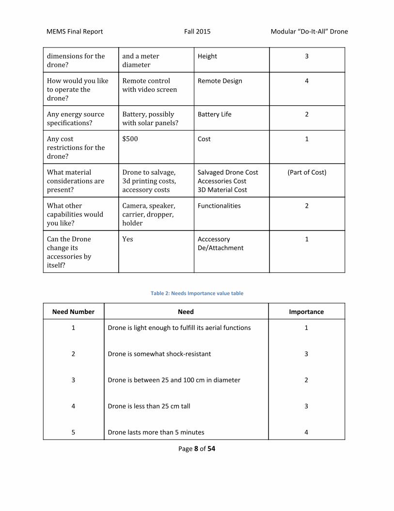
Table 1: Critical Questions, customer statements and interpreted needs Table
Questions Customer Statement Interpreted Need Importance
How heavy or light do you want the device?
The lighter the better.
Weight 1
How durable do you want the device?
Durable enough to sustain some shock from falling from a small height.
Durability 3
What are the idea Between a Frisbee Width 2
Page 7 of 54
MEMS Final Report Fall 2015 Modular “Do-It-All” Drone
dimensions for the drone?
and a meter diameter
Height 3
How would you like to operate the drone?
Remote control with video screen
Remote Design 4
Any energy source specifications?
Battery, possibly with solar panels?
Battery Life 2
Any cost restrictions for the drone?
$500 Cost 1
What material considerations are present?
Drone to salvage, 3d printing costs, accessory costs
Salvaged Drone Cost Accessories Cost 3D Material Cost
(Part of Cost)
What other capabilities would you like?
Camera, speaker, carrier, dropper, holder
Functionalities 2
Can the Drone change its accessories by itself?
Yes Acccessory De/Attachment
1
Table 2: Needs Importance value table
Need Number Need Importance
1
2
3
4
5
Drone is light enough to fulfill its aerial functions Drone is somewhat shock-resistant Drone is between 25 and 100 cm in diameter Drone is less than 25 cm tall Drone lasts more than 5 minutes
1
3
2
3
4
Page 8 of 54

MEMS Final Report Fall 2015 Modular “Do-It-All” Drone
6
7
8
9
Drone cost less than $500 Drone has at least 3 functions Drone can attach/detach accessories Drone has a long battery duration
1
2
1
1
3.1.2 List of identified metrics
Table 3: List of identified needs and metrics
Metric Number
Associated Needs
Metric Units Min Value
Max Value
1
2
3
4
5
6
7
8
9
1,2,4
1,2,3
1,2,3,4
7
3,4,7
7,8
7,8
8,9
1,6
Height Diameter Structural Strength Salvaged Drone Cost 3D Printed Frame Cost Accessories Cost Number of Functions Can attach/detach accessories Battery Duration
cm cm cm (height dropped) Dollars Dollars Dollars Integer Binary Integer
10
25
0
50
5
20
0
0
1
30
100
150
200
40
200
3
1
10
3.1.3 Table/list of quantified needs equations Table 4: Quantified Needs Equations
Page 9 of 54

MEMS Final Report Fall 2015 Modular “Do-It-All” Drone
Page 10 of 54
MEMS Final Report Fall 2015 Modular “Do-It-All” Drone
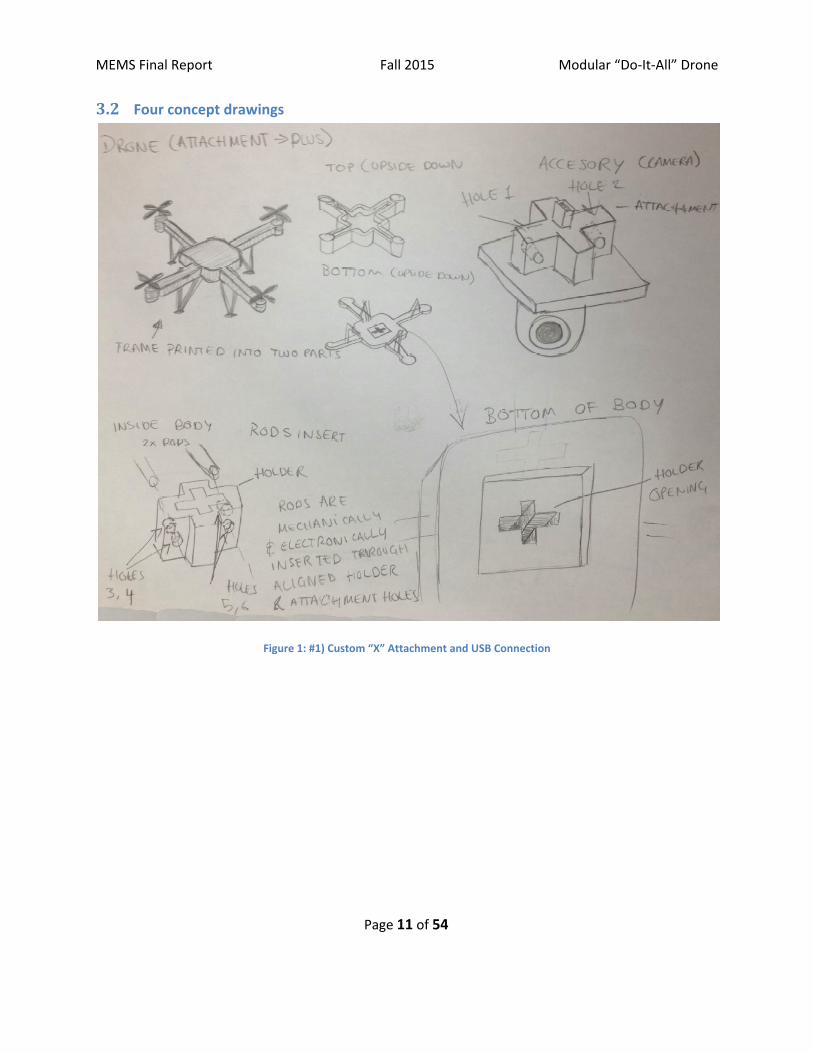
3.2 Four concept drawings
Figure 1: #1) Custom “X” Attachment and USB Connection
Page 11 of 54

MEMS Final Report Fall 2015 Modular “Do-It-All” Drone
Figure 2: #2) Electromagnet and Wi-Fi
Page 12 of 54

MEMS Final Report Fall 2015 Modular “Do-It-All” Drone
Page 13 of 54

MEMS Final Report Fall 2015 Modular “Do-It-All” Drone
Figure 3: #3) Buckle, Dock, and USB Connection
Figure 4: #4) Span-On and USB Connection
3.3 A concept selection process
3.3.1 Concept scoring
Page 14 of 54

MEMS Final Report Fall 2015 Modular “Do-It-All” Drone
Page 15 of 54

MEMS Final Report Fall 2015 Modular “Do-It-All” Drone
Figure 5: User Needs Metrics Table
Figure 5: User Needs Metric Table
3.3.2 Preliminary analysis of each concept’s physical feasibility
Design #1) Custom “X” Attachment and USB Connection:
A large difficulty in designing the plus-sign attachment is the additional weight and cost
caused by the extra motor, needed to move the rods used to fix the accessory
attachment. The plus-sign attachment ensures the stability of the accessory, and
additionally, seamlessly adapts it into the drone, completing a simple and clean design.
Another difficulty comes from adapting accessories into the required plus sign
attachment. Worst case scenario, the accessory becomes a little bulky. However, the
two-piece drone frame has the large benefit of being easy to print through 3D printing,
due to its simple design with flat surfaces on each piece. Furthermore, 3D printing has
the benefit that, if the frame breaks, it can be reprinted for a very cheap cost.
Design #2) Electromagnet and Wi-Fi:
Concept 2 relies on attaching and de-attaching a component to a drone via an
electromagnet. The mechanism of this concept is fairly simple, as it has no moving
parts in the attachment and dis-attachment. Unlike a fully-mechanical mechanism, this
concept will require extra sources of energy (i.e. current) in order to operate the
Page 16 of 54
MEMS Final Report Fall 2015 Modular “Do-It-All” Drone
electromagnet, and it would require a separate radio control device to cease or
continue the current. Manufacturing would be fairly simple. The electromagnet would
come from a third party, and wiring in the drone casing would be fairly simple. The
electromagnet will come with possible attachments, and could be glued on in the
cheapest scenario. A difficulty that arises with this concept is the extra weight that may
inhibit the operation of the drone. A benefit is that the drone does not have to be fully
aligned with the attachment to effectively pick it up.
Design #3) Buckle, Dock, and USB Connection:
The design of Concept 3 proposes to solve the issue of picking up, retrieving, carrying,
and reloading an interchangeable device with a buckle mechanism, similar to that on a
traditional backpack. Our project inherently will face the difficulties of lifting items due
to their weight and simple operation of picking the device up. The drone itself
embodies a quad-copter design, with four propellers located equidistantly from the
center base of the drone. Additionally, the base and the blades will be designed and
3D-printed, drawing from inspiration from existing models of successful drone
technology. The design of the device platform features 2 male buckle components,
facing upwards, opposite of each other on the port and starboard sides of the platform.
Every interchangeable device will hold a standard device platform, allowing for simple
exchange. The bottom of the base will feature two female buckle components,
attaching to the male component on the device platform. The loading dock allows for
the drone to be guided to the landing spot with the four aligning arms. It holds a
cylindrical base to hold the device platform, with magnets to hold it in the correct
place. It also features a mechanism that will allow it to detach the male and female
buckles from each other.
Design #4) Snap-On and USB Connection:
A large difficulty of accommodating multiple interchangeable attachments for a drone
is being able to quickly and easily attach and detach the different components while
still ensuring a secure connection between the component and the drone. Attaching
the components implementing spring-loaded teeth on both the component and the
drone’s receiving port is a viable option without much additional weight, and no
necessary motors. Simply, when the component is slid into the port, its teeth are
compressed until it passes the teeth of the port, at which point the spring releases and
the component is locked into place. In order to release the component, push on the
tabs of the port to compress the spring and retract the teeth of the port, allowing the
component to easily slide out. Another difficulty pertaining to multiple attachments is
the customization of data connection concerning each specific part. A flashlight
requires power to illuminate, as does a payload for the doors to open, and a gripper to
operate the hand, while a camera requires both power and a way to transmit the data
Page 17 of 54
MEMS Final Report Fall 2015 Modular “Do-It-All” Drone
so that the pilot is able to receive a live video feed and can pilot the drone in first
person. It appears that this is possible by making the connection a USB connection in
order to satisfy the different needs of each component. This still create a more costly
and complex connection than a simple power source, but is needed to the goals of the
product.
3.3.3 Final summary
Winner: Design #3) Buckle, Dock, and USB Connection
Concept 3 has several advantages, primarily in its design of the loading dock, along with
the universality of the device platform. Similar to the other concepts, it features a
lightweight drone, with four arms, each holding a propeller in a quad-copter fashion. It
faults in the complexity of the drone base design, though combined with the simplicity
of design of Concept 4 and the versatility of Concept 1, it will succeed in achieving
aerodynamics capable of flight. The alignment arms guide the drone to the same
location during each landing and takeoff, allowing for easy transfer of the
interchangeable device. The attachment mechanism will merge with the feasibility of
Concept 1, inhibited by electro-restrictions in Concept 4. Adapting from Concept 1, a
USB connection will be utilized to redirect all controls to one central Arduino board.
The design has few protruding sharp edges, and should pose no significant danger to
pedestrians passing by. It consists of few moving parts other than the blades, and has a
relatively simple mechanism.
3.4 Proposed performance measures for the design
Performance Goals:
1. Drone can fly for at least 5 minutes.
2. Drone has at least 3 different accessories.
3. Overall costs are $500 or less.
4. Drone is 40 cm in diameter.
5. Drone is 25 cm in height.
6. Drone can sustain a drop from an altitude of 1 meter.
7. Drone can attach and detach to accessories without manual help.
8. Drone weighs less than 1 pound.
Page 18 of 54
MEMS Final Report Fall 2015 Modular “Do-It-All” Drone
4 Embodiment and fabrication plan
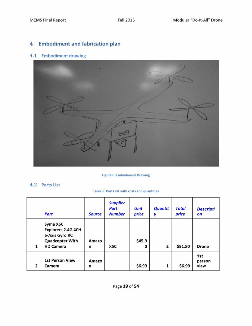
4.1 Embodiment drawing
Figure 6: Embodiment Drawing
4.2 Parts List Table 5: Parts list with costs and quantities
Part Source
Supplier Part Number
Unit price
Quantity
Total price
Description
1
Syma X5C Explorers 2.4G 4CH 6-Axis Gyro RC Quadcopter With HD Camera
Amazon X5C
$45.90 2 $91.80 Drone
2 1st Person View Camera
Amazon $6.99 1 $6.99
1st person view
Page 19 of 54

MEMS Final Report Fall 2015 Modular “Do-It-All” Drone
3 Accessory Flashlight
Amazon $9.95 1 $9.95
Illuminate ground
4 RF Remote Control Adafruit
$10.95 1 $10.95
RF transmitter
5 RF Receiver Adafruit $9.82 1 $9.82
RF receiver
6 USB Extension Amazon $3.12 1 $3.12
Malefemale USB cord
7 Arduino Amazon
$15.90 1 $15.90
Microcontroller
8 Fabricated Attachment Box
Art School Custom $20.90 1 $20.90
Original electronics box
9 Fabricated Attachment Buckle
Art School Custom $7.30 1 $7.30
Original accessory attachment
10 Fabircated Platform
Art School Custom $27.30 1 $27.30
Hold attachment
11 Power Truck Radio Control Truck Lift
Amazon
FD2695B $14.95 1 $14.45
To raise the docking platform
12 Zippy #1 Type Knife
Campus Bookstore
008618177 $2.75 1 $2.95
To cut the wood for the electronics box
13 Basswood 3/32x1x24 15 Pcs
Campus Bookstore
000206207 $1.18 1 $1.26
To make the electronics box
14 Basswood 3/16x1/4x24 30 Pcs
Campus
000216017 $0.50 1 $0.54
To make the
Page 20 of 54

MEMS Final Report Fall 2015 Modular “Do-It-All” Drone
Bookstore
electronics box
15 Basswood Sheet 1/16x6x24 10 Pcs
Campus Bookstore
000216036 $5.52 2 $11.82
To make the electronics box
16
Art/Print/Photographic Supply (Box Cutter)
Campus Bookstore
000000074 $2.50 1 $2.68
Boxcutter to cut thicker wood
17 Super Glue
Campus Bookstore
000000074 $5.99 1 $6.42
To assemble parts with strength
$259.1
0
Page 21 of 54

MEMS Final Report Fall 2015 Modular “Do-It-All” Drone
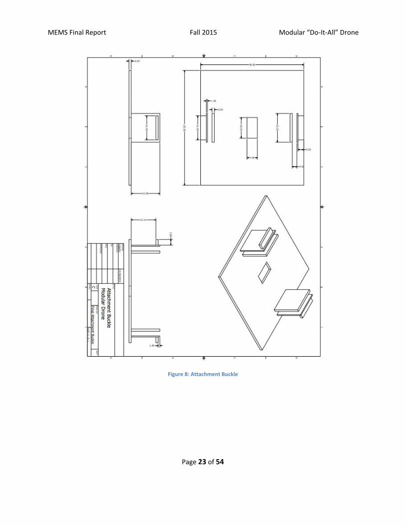
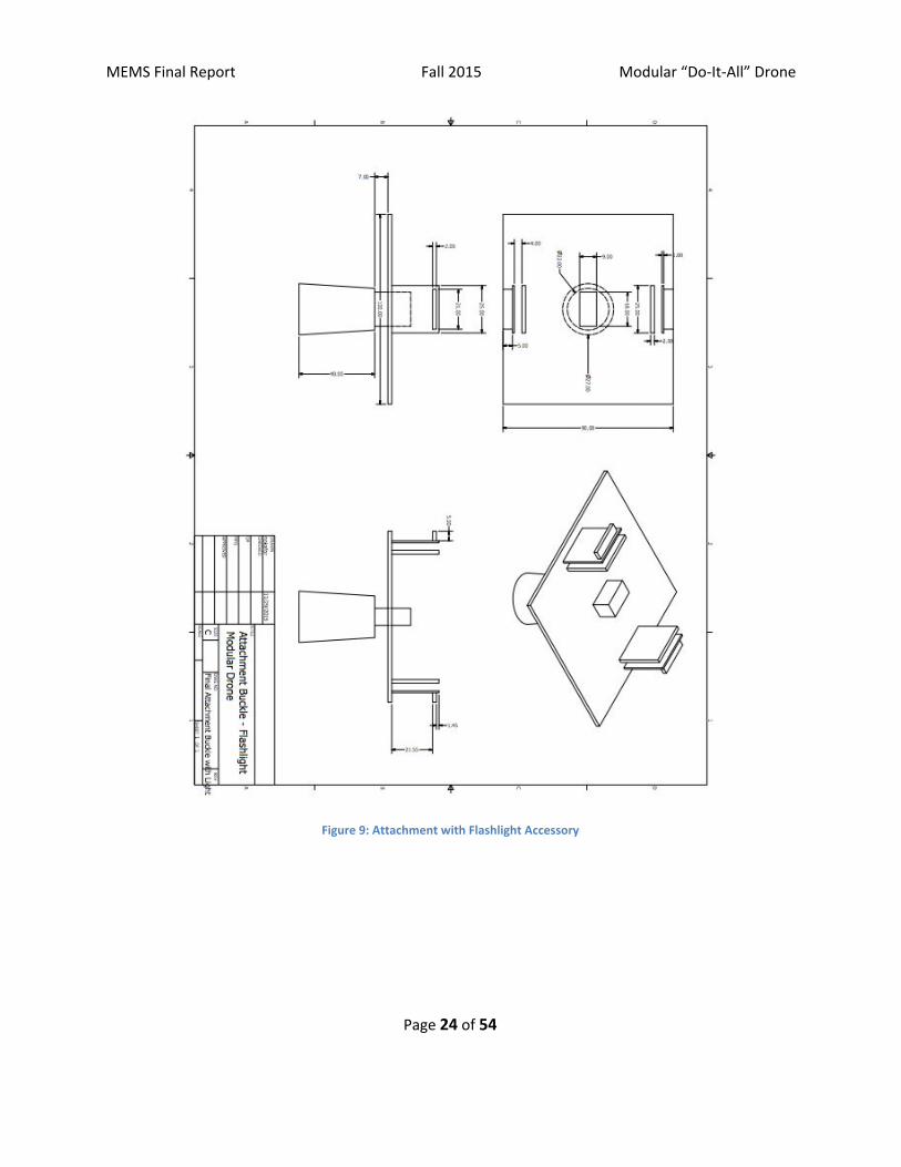
4.3 Draft detail drawings for each manufactured part
Figure 7: Electronics Box
Page 22 of 54
MEMS Final Report Fall 2015 Modular “Do-It-All” Drone
Figure 8: Attachment Buckle
Page 23 of 54
MEMS Final Report Fall 2015 Modular “Do-It-All” Drone
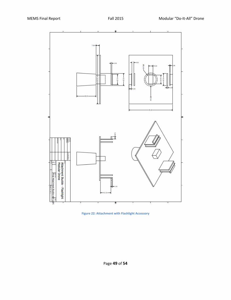
Figure 9: Attachment with Flashlight Accessory
Page 24 of 54

MEMS Final Report Fall 2015 Modular “Do-It-All” Drone
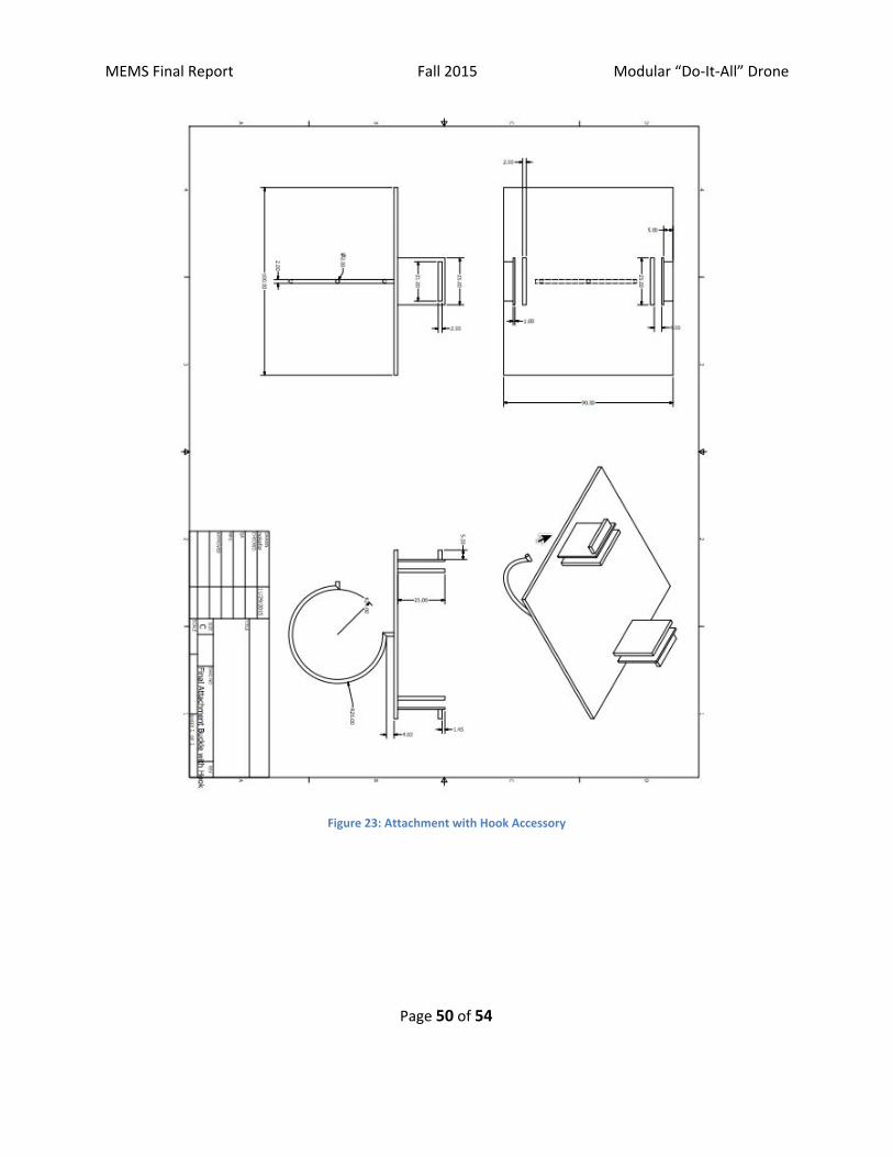
Figure 10: Attachment with Hook Accessory
Page 25 of 54

MEMS Final Report Fall 2015 Modular “Do-It-All” Drone
Figure 11: Attachment Platform
4.4 Description of the design rationale for the choice/size/shape of each part
For the most effective modular drone, we determined that the housing and structural material
needed to be as light as possible. 3D printed material was originally chosen to construct all of our
structural components, because the material is reasonably strong, and it is easy to make the parts
Page 26 of 54

MEMS Final Report Fall 2015 Modular “Do-It-All” Drone
to our design specifications with this material. However, the drone purchased to base our
product off of was very cheap, and therefore did not produce enough thrust to carry much more
than itself and still be capable of flight.
Due to weight considerations, basswood was chosen as our prototyping material. While not
particularly strong, basswood is extremely light and easy to work with, so that it would be
possible to show a proof of concept. For this reason, basswood was chosen to be the material of
all the attachment platforms and mechanisms, as well as the box to house the electronics and
extension cables.
Because of the size of the Arduino, the electronics box was required to be rather large, which
added additional weight to the overall design. A rectangular shape was used to fit the arduino,
and also because the aerodynamics of the drone were not a driving factor into our design, since
the aircraft does not move laterally at fast speeds for a large amount of time. The size of the
attachment platform had to match the size of the electronics box so that the attachment
mechanism would work properly, which further added material and weight to the payload of the
drone, further limiting its flight capability.
For a commercial product, more abilities are available to use. Instead of 3D printing or
basswood, extremely light and thin injection plastics can be employed for the structural
components of the drone and its modular capabilities. Injection plastics will ensure a lightweight
yet strong structure will more flight capability. Another big change to a commercial product
would be that instead of a reprogrammable Arduino microcontroller, the electronics would be
controlled by a industrial mass-produced chip, which is less than a tenth of the size of the
Arduino, and requires less power. This saves weight on batteries, which contributed a lot to the
weight of the electronics box. This change also requires less space, meaning that the box and
attachment platform can be much smaller, further reducing weight.
Page 27 of 54
MEMS Final Report Fall 2015 Modular “Do-It-All” Drone
5 Engineering analysis
5.1 Engineering analysis proposal
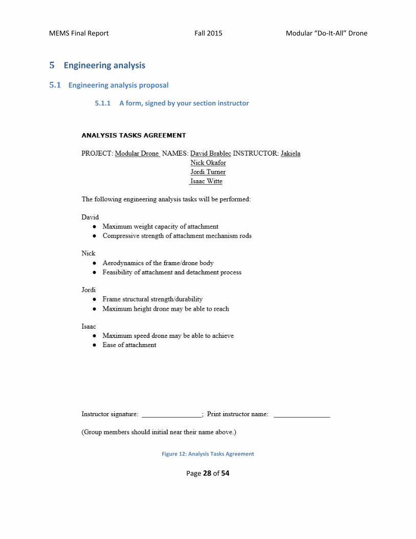
5.1.1 A form, signed by your section instructor
Figure 12: Analysis Tasks Agreement
Page 28 of 54

MEMS Final Report Fall 2015 Modular “Do-It-All” Drone
5.2 Engineering analysis results
5.2.1 Maximum Weight Capacity of the Attachment
The maximum weight capacity of the drone is 209 g, meaning that the maximum weight of an attachment is 100 g. In a commercial product a drone with greater lift capability would be used, or a custom made drone would be manufactured with the ability to lift several times its own weight. The reason that the prototype drone was chosen was its minimal cost, and does not fulfill the needs of our product for commercial satisfaction.
5.2.2 Compressive Strength of the Attachment Mechanism Rods
The compressive strength of the attachment mechanism rods is 0.3926 N. This force signifies the force needed to bend the outer buckle as far as it can go until it reaches the inner buckle, which provides the attachment buckle additional strength and rigidity.
5.2.3 Aerodynamics of the Frame/Drone Body
Because we began with an already working drone and frame, the aerodynamics were
not changed. The frame remained the same, with very few edges so that the airflow is
not separated. The electronics box and attachments are in the shape of square, due to
the shape and size of the electronics. The commercial product would have a small
industrial microchip to handle all of the electronics, so the box and attachments could
be much smaller and more curved to have a more aerodynamic shape.
5.2.4 Feasibility of Attachment and Detachment Process
Our attachment and detachment mechanism are very feasible and simple, but is
manual. The autonomous mechanism has been theoretically solved but was not
applied for this class. Theoretically, the drone would land in the capture area, which is
slanted downward so that the drone has a controlled descent until it has reached the
bottom of the dock. Once that point is reached, and IR sensor is triggered, which then
causes a motor to raise a platform and attaches the component to the drone. In order
to also facilitate detachment another sensor would have to be employed to tell if there
was a component already detached, as well as a more advanced gripper mechanism
that is capable of nimble detaching the component and moving is away from the drone
so that it can be replaced.
5.2.5 Structural Strength
The original drone is able to sustain repeated falls without damage, so its structural strength is sound. With the prototype box this strength fell, as the box was made of weak balsawood material. The commercial product would be injection plastic
Page 29 of 54

MEMS Final Report Fall 2015 Modular “Do-It-All” Drone
material and would be securely fastened to the drone, so the structural strength would be the same as the original drone. If additional durability was needed wider legs with shock absorbent springs could be manufactured.
5.2.6 Maximum Height
When modified the drone was only able to reach the height of 6 inches. This is because
the components used throughout this project were chosen on the baseness of cost and
ability to change our ideas. Instead of a condensed industrial microchip we used the
editable microcontroller Arduino, and used commercial batteries instead of industrial
ones. Additionally, the drone picked was a very cheap drone with very little lift
capabilities, and for a commercial application a better drone would be used.
5.2.7 Maximum Speed
Ground speed is not as applicable for drones, as it is rare for the user to desire a drone to move as quickly horizontally as possible. In addition, the modified drone had limited flight capability, so the maximum speed is even less relevant.
5.2.8 Ease of Attachment
Our attachment process was extremely simple, and required only one or two seconds
with minimum force needed. All that is required is to make sure the component is
facing the correct direction so that the ports line up, and then apply inward pressure to
the outer buckle and ease the component upward into the electronics box, until the
outward buckle reaches the window in the box and locks into place. In order to detach
a mechanism, apply downward and inward pressure on the outer buckle through the
window in the box until the component slides out and fully detaches.
6 Working prototype
6.1 A preliminary demonstration of the working prototype
This video (https://youtu.be/_lh_-7HqpGc?t=1m41s) shows one our final prototypes. Initially, we
show how the attachment mechanism works, and how each of the 3 sample attachments
mechanically fit into the attachment box retrofit on the drone. The mechanical attachment
mechanism is a buckle system.
The hook is solely a mechanical attachment. Once the attachment buckles into the attachment box, it
is ready to go!
The camera needs to connect electrically on top of mechanically. There is a video data connection
port for the camera to connect to the electronics in the attachment box. Once the drone is turned on,
the camera turns on as well. It is connected to the central chip in the drone.
Page 30 of 54

MEMS Final Report Fall 2015 Modular “Do-It-All” Drone
The flashlight connects to the electronics in the attachment box via a USB connection. The Arduino
and a remote control shield allow the flashlight to be controlled on and off by a remote control that
has a range of up to 100 feet. All programming was custom programming, and code for attachments
like this on drones is something that has not been patented of pursued.
Page 31 of 54

MEMS Final Report Fall 2015 Modular “Do-It-All” Drone
6.2 Prototype photos
Figure 13: Front View of Entire System – Drone and Attachment Box
Page 32 of 54

MEMS Final Report Fall 2015 Modular “Do-It-All” Drone
Figure 14: Inside View of Electronics in Attachment Box
Page 33 of 54

MEMS Final Report Fall 2015 Modular “Do-It-All” Drone
Figure 15: Three Possible Attachments – Camera, Hook, Flashlight
Page 34 of 54
MEMS Final Report Fall 2015 Modular “Do-It-All” Drone
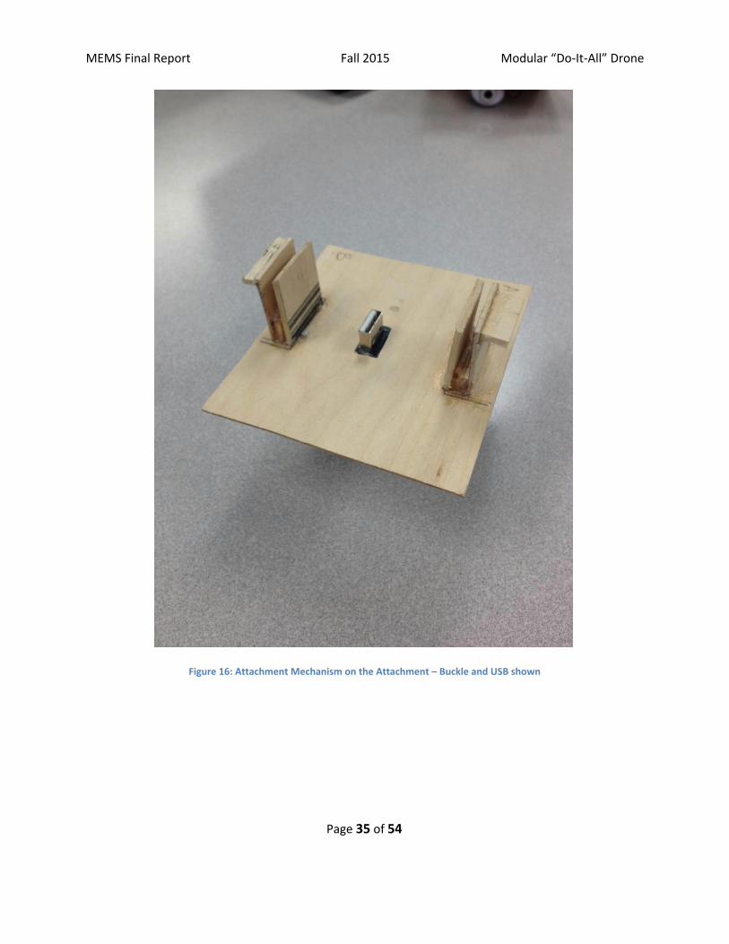
Figure 16: Attachment Mechanism on the Attachment – Buckle and USB shown
Page 35 of 54
MEMS Final Report Fall 2015 Modular “Do-It-All” Drone
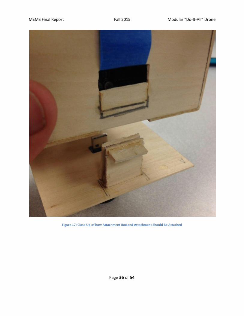
Figure 17: Close Up of how Attachment Box and Attachment Should Be Attached
Page 36 of 54

MEMS Final Report Fall 2015 Modular “Do-It-All” Drone
Figure 18: Attachment Box and Attachment Shown Attached
6.3 A short videoclip that shows the final prototype performing
This video clip (https://youtu.be/_lh_-7HqpGc?t=1m41s) shows our final working prototype in use. It
can be seen that it fulfills most of our key design metrics. It can be operated by a single user, the
drone is able to fly, and the attachments are able to connect electromechanically.
Page 37 of 54
MEMS Final Report Fall 2015 Modular “Do-It-All” Drone
7 Design documentation
7.1 Final Drawings and Documentation
7.1.1 A set of engineering drawings that includes all CAD model files and all
drawings derived from CAD models.
The CAD drawings can be found in Appendix C.
7.2 Final Presentation
7.2.1 A link to a video clip of final presentation
Our final PowerPoint presentation with audio is uploaded to Youtube at the
address: https://www.youtube.com/watch?v=SysObdTKC8E
Page 38 of 54
MEMS Final Report Fall 2015 Modular “Do-It-All” Drone
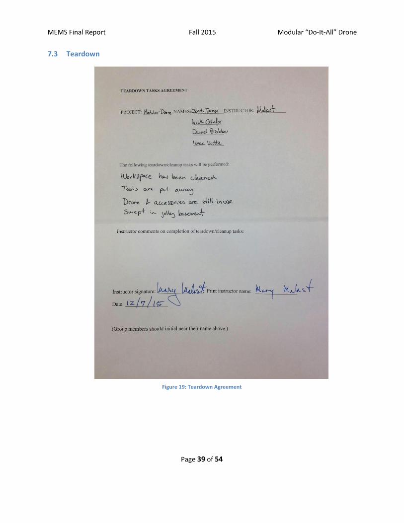
7.3 Teardown
Figure 19: Teardown Agreement
Page 39 of 54
MEMS Final Report Fall 2015 Modular “Do-It-All” Drone
8 Discussion
8.2 Using the final prototype produced to obtain values for metrics, evaluate the quantified
needs equations for the design. How well were the needs met? Discuss the result.
Our final prototype met all of our user needs metrics as expected. The accessories could be
easily attached and detached, mechanically and electrically – all in less than 10 seconds. The
drone has three functions: a camera, a flashlight, and a hook. The drone more than 5 minutes
(approximately 7 minutes while on). The overall project cost us less than $300, and that could
be greatly reduced. Size-wise, the width of the drone is in our ranges (31cm) and so is the
height, at 25 cm.
The only need we barely met was the capability to fly, as the drone with an accessory attached
weight only slightly under the maximum weight limit. However, it did hover, and that could be
easily remedied by using a more powerful drone.
8.3 Discuss any significant parts sourcing issues? Did it make sense to scrounge parts? Did
any vendor have an unreasonably long part delivery time? What would be your
recommendations for future projects?
Overall, our sourcing went very well. Our largest sourcing issue came down to the cost of the drone, as we wanted to buy a powerful drone, but realized the chance of having to rebuy the drone in case of a mistake or the drone not fulfilling our needs. Due to our restricted budget, and most drones costing over $250, we used a small, $45 yet versatile drone for our project.
Additionally, another issue was the time and cost of 3D printing. Communicating with the Art School proved to be difficult, and their printer is extremely slow. For this reason, we decided to switch over to creating a wooden prototype. However, 3D printing definitely has a strong advantage in precision and strength.
Scrounging parts did not make sense for the most part, as the mechanical structure needed to be as small and light as possible, and it would be difficult to find a part that would fit the size requirements without being custom-made. On the other hand, if the electronics can be scrounged, it would greatly reduce the cost, but this does come with the issue of wear and tear on the electronics - which can make the entire drone not work if an electrical component gives out. The parts we ordered from Amazon were reliable and came fairly quickly, thanks to Amazon Prime.
For future projects, I would recommend using Amazon Prime to order electrical components, as that worked very well for us, both in terms of effectiveness, time and cost. Moreover, I would recommend buying cheap drones - it is easy to test if the concept works and later scale the drone power to fully function. Finally, it would be best to create a
Page 40 of 54

MEMS Final Report Fall 2015 Modular “Do-It-All” Drone
functioning model out of balsa wood, and then use a 3D printer. This accelerates the process, and reduces extraneous costs.
8.4 Discuss the overall experience:
8.4.1 Was the project more of less difficult than you had expected?
The project was more difficult than we expected. There were many issues we did not
expect to encounter: intermittent functioning from the electronics, difficulty with 3D
printing, drone power limitations, the imprecise control over the drone’s flight, and the
complexity of automating the accessory attachment and detachment.
8.4.2 Does your final project result align with the project description?
Our final project was able to use various accessories, all of which could be easily and
quickly changed. However, the drone could barely fly with the accessories, and we
were unable to have accessories automatically attach and detach.
8.4.3 Did your team function well as a group?
Our group worked very well together. We have all known each other for some time,
and we were very effective at splitting up tasks working on them individually or in
groups. The work was given to suit each member’s strengths, and worked out pretty
well.
8.4.4 Were your team member’s skills complementary?
Our skills were extremely complimentary. Our different skills included circuitry,
soldering, programming, CAD, marketing, and design experience. Overall, we all had a
good understanding of mechanics. This turned out to be instrumental in working
designing our project.
8.4.5 Did your team share the workload equally?
The workload was split equally. We frequently worked together, but we always took
into account the individual work from each member. The type of work for each
member varied according to their strengths and skills, but the difficulty remained equal
for everyone.
8.4.6 Was any needed skill missing from the group?
The skills missing from the group at first was experience maneuvering the drone and
familiarity with 3D printing. Aside from that, we had everything we needed with each
group member’s individual expertise. Overall, we had the skills required, even if they
needed to be polished.
Page 41 of 54

MEMS Final Report Fall 2015 Modular “Do-It-All” Drone
8.4.7 Did you have to consult with your customer during the process, or did you
work to the original design brief?
We consulted Professor Jakiela and Professor Malast about the interest and
characteristics of our projects, along with the idea of the automated docking drone.
However, our project was very loyal to the original design brief.
8.4.8 Did the design brief (as provided by the customer) seem to change during the
process?
Our design brief stayed fairly constant. Originally, we only looked at a modular drone,
but after talking with our customer, we added the stretch goal of the automated
docking base, but that goal was sadly too optimistic. Nevertheless, the modular
product still remained a good product, with high marketing value.
8.4.9 Has the project enhanced your design skills?
Yes, the project has definitely increased our design skills. The entire team has either
gained or expanded their skills with electromechanical products, be it with soldering, or
working with wood. We all understand better the approach necessary to successfully
create a product, along with how to organize the process and timeline.
8.4.10 Would you now feel more comfortable accepting a design project assignment
at a job?
Yes, the entire group feels more comfortable accepting a job involving a design project.
We all have a better grasp of the entire project timeline, from conception to creation
to modification. Furthermore, we are all searching for product design opportunities, as
we found the project to be meaningful, interesting and occasionally fun.
8.4.11 Are there projects that you would attempt now that you would not attempt
before?
This project has opened up many projects including both mechanics and electronics.
The team has gained a lot of experience in creating a product under financial and time
constraints, which will be valuable for any sort of work or product. Furthermore, this
project heightened our experience working closely with teams of different experiences
and backgrounds, which is useful for any type of project.
Page 42 of 54

MEMS Final Report Fall 2015 Modular “Do-It-All” Drone
9 Appendix A - Parts List Table 7: Detailed parts list
Part
Color, TPI, other part
IDs
Syma X5C Explorers 2.4G 4CH
6-Axis Gyro RC Quadcopter With
HD Camera White Plastic
1st Person View Camera Metallic Black
Accessory Flashlight Black Metal
RF Remote Control Black Plastic
RF Receiver Black Plastic
USB Extension Black Plastic
Arduino Blue Plastic
Fabricated Attachment Box White Plastic
Fabricated Attachment Buckle White Plastic
Fabircated Platform White Plastic
Power Truck Radio Control Truck Lift Orange Plastic
Zippy #1 Type Knife Metallic
Basswood 3/32x1x24 15 Pcs Wood
Basswood 3/16x1/4x24 30 Pcs Wood
Basswood Sheet 1/16x6x24 10 Pcs Wood
Art/Print/Photographic Supply (Box Cutter) Metallic
Super Glue Clear Plastic
Page 43 of 54

MEMS Final Report Fall 2015 Modular “Do-It-All” Drone
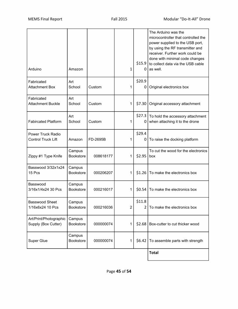
10 Appendix B - Bill of Materials Table 8: Bill of materials
Part Source
Supplier Part
Number
Quantity Total
price Description
Syma X5C Explorers
2.4G 4CH 6-Axis
Gyro RC Quadcopter
With HD Camera Amazon X5C 2
$91.8
0
We chose this drone due to its cost, size (31cmx31cmx8cm), good reviews, and the included camera. Powerful enough to lift enough weight for this project
1st Person View
Camera Amazon 1 $6.99 To help pilot the camera
Accessory Flashlight Amazon 1 $9.95 To illuminate the ground beneath the drone
RF Remote Control Adafruit 1
$10.9
5
The purpose of the RF remote control is to transmit a radio frequency that is received by the RF receiver inside the electronics box. Together the power to the USB connection can either be turned on or off
RF Receiver Adafruit 1 $9.82
The prupose of the receiver is to receive the radio frequency from the transmitter and to signal the Arduino, controlling the power to the USB port.
USB Extension Amazon 1 $3.12
We chose this to use the female USB port, which we soldered to wires connected to the Arduino.
Page 44 of 54
MEMS Final Report Fall 2015 Modular “Do-It-All” Drone
Arduino Amazon 1
$15.9
0
The Arduino was the microcontroller that controlled the power supplied to the USB port, by using the RF transmitter and receiver. Further work could be done with minimal code changes to collect data via the USB cable as well.
Fabricated Attachment Box
Art School Custom 1
$20.9
0 Original electronics box
Fabricated Attachment Buckle
Art School Custom 1 $7.30 Original accessory attachment
Fabircated Platform Art School Custom 1
$27.3
0 To hold the accessory attachment when attaching it to the drone
Power Truck Radio Control Truck Lift Amazon FD2695B 1
$29.4
0 To raise the docking platform
Zippy #1 Type Knife Campus Bookstore 008618177 1 $2.95
To cut the wood for the electronics box
Basswood 3/32x1x24 15 Pcs
Campus Bookstore 000206207 1 $1.26 To make the electronics box
Basswood 3/16x1/4x24 30 Pcs
Campus Bookstore 000216017 1 $0.54 To make the electronics box
Basswood Sheet 1/16x6x24 10 Pcs
Campus Bookstore 000216036 2
$11.8
2 To make the electronics box
Art/Print/Photographic Supply (Box Cutter)
Campus Bookstore 000000074 1 $2.68 Boxcutter to cut thicker wood
Super Glue Campus Bookstore 000000074 1 $6.42 To assemble parts with strength
Total
Page 45 of 54

MEMS Final Report Fall 2015 Modular “Do-It-All” Drone
$259.10
Page 46 of 54
MEMS Final Report Fall 2015 Modular “Do-It-All” Drone
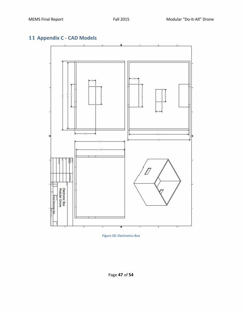
11 Appendix C - CAD Models
Figure 20: Electronics Box
Page 47 of 54

MEMS Final Report Fall 2015 Modular “Do-It-All” Drone
Figure 21: Attachment Buckle
Page 48 of 54
MEMS Final Report Fall 2015 Modular “Do-It-All” Drone
Figure 22: Attachment with Flashlight Accessory
Page 49 of 54
MEMS Final Report Fall 2015 Modular “Do-It-All” Drone
Figure 23: Attachment with Hook Accessory
Page 50 of 54

MEMS Final Report Fall 2015 Modular “Do-It-All” Drone
Figure 24: Attachment Platform
Page 51 of 54

MEMS Final Report Fall 2015 Modular “Do-It-All” Drone
12 Annotated Bibliography
Anscher, Joseph. "Patent US5546642 Siderelease Buckle Fastener."Google Books. National Molding Corporation, 5 Aug. 1994. Web. 07 Dec. 2015.
http://www.google.com/patents/US5546642
This is the patent for the side-release buckle. This design was the main framework from which our idea was extrapolated. Branching from this, we were able to solve the modularity aspect of our drone and make sure that we could attach and detach accessories safely and securely.
"10 Best Drones 2015." YouTube. YouTube, n.d. Web. 07 Dec. 2015.
https://www.youtube.com/watch?v=bUWw5xKejpo
The “10 Best Drones 2015” video served as excellent inspiration as we went through the process of selecting the drone to purchase. We had to do an in depth review of the drones available to us online, and rated multiple based on flight capability, weight capacity, and price. From there, we were able to choose the most appropriate drone for selection that would accurately fit the needs of our senior design project.
"Top 5 Drone Inventions You Must Have." YouTube. YouTube, n.d. Web. 07 Dec. 2015. <https://www.youtube.com/watch?v=_l6CQRHIGyg>.
This video, “Top 5 Drone Inventions You Must Have”, allowed us to expand our own thoughts about the set capabilities a drone can have. We saw the possibilities in expansion past the traditional drone structure, and as part of our research, we identified a gap in modularity, something we chose to hone in on to specialize our attachment feature.
"SideRelease Buckle Kit by Gear Aidâ¢." YouTube. YouTube, n.d. Web. 07 Dec. 2015. <https://www.youtube.com/watch?v=lLZDSgF83ug>.
This is a video which outlines the capabilities of the side release buckle. This is the design which proved the foundation for the attachment mechanism we created and expanded upon. This shows the strength capacity and versatility of the buckle, features that made it stands out as the optimum mode of connected the accessory to the drone itself.
Page 52 of 54

MEMS Final Report Fall 2015 Modular “Do-It-All” Drone
South Asia. "Drones: What Are They and How Do They Work? BBC News."BBC News. BBC News Source, 31 Jan. 2012. Web. 07 Dec. 2015. <http://www.bbc.com/news/worldsouthasia10713898>.
This article outlined some of the popularity and controversy surrounding drone technology. It analyzed the role it played within the US Army and how it is being utilize for warfare. Yet, it expanded past this and showcased some of the other uses for the technology, and why it has grown so popular in such a short amount of time in our society.
"What Is Drone? Definition from WhatIs.com." WhatIs.com. N.p., n.d. Web. 07 Dec. 2015. <http://whatis.techtarget.com/definition/drone>.
From this article, we were able to understand the basic definition of drones. This was what was shown to us, and helped guide us along the way to understand the technology we would be using throughout the semester. “Drones are more formally known as unmanned aerial vehicles (UAV). Essentially, a drone is a flying robot. The aircraft may be remotely controlled or can fly autonomously through software-controlled flight plans in their embedded systems working in conjunction with GPS. UAVs have most often been associated with the military but they are also used for search and rescue, surveillance, traffic monitoring, weather monitoring and firefighting, among other things.”
"How I Accidentally Kickstarted the Domestic Drone Boom." Wired.com. Conde Nast Digital, n.d. Web. 07 Dec. 2015. <http://www.wired.com/2012/06/ff_drones/>.
This article from Wired gave amazing insight on the drone boom of this past decade. It showed some reasons for the mass popularity it has gained over the past couple years, and how it has even outnumbered US military drones for shear domestic purposes.
Page 53 of 54