Embed Size (px)
Citation preview

COPYRIGHT - 1982
MOOG MUSIC INC.
MANUAL NO. 997-045924-001
®
MEMORYMOOG
MODEL 345
OWNERS andSERVICE MANUAL
for
This binder contains the complete owners and technical manuals for the Memorymoog.
As updates and improvements are made in the instrument, they will be described in the
Addenda section in the back of the manual.
iii
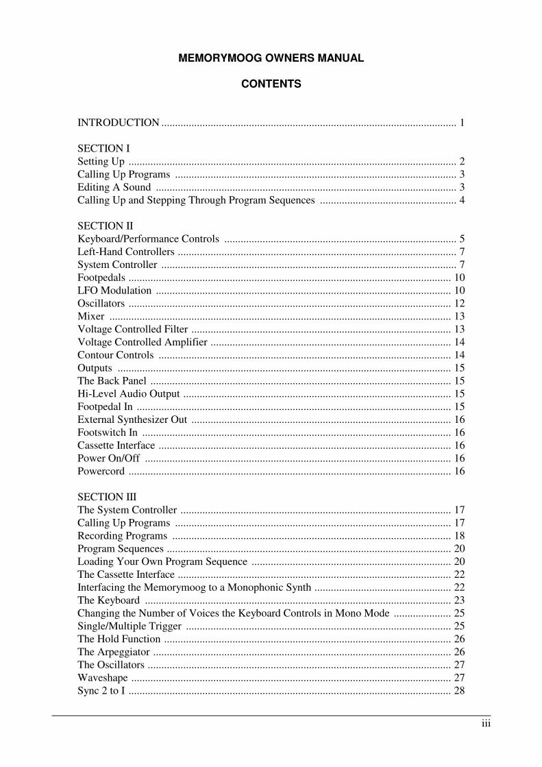
MEMORYMOOG OWNERS MANUAL
CONTENTS
INTRODUCTION ............................................................................................................ 1
SECTION I
Setting Up ........................................................................................................................ 2
Calling Up Programs ....................................................................................................... 3
Editing A Sound .............................................................................................................. 3
Calling Up and Stepping Through Program Sequences .................................................. 4
SECTION II
Keyboard/Performance Controls ..................................................................................... 5
Left-Hand Controllers ...................................................................................................... 7
System Controller ............................................................................................................ 7
Footpedals ...................................................................................................................... 10
LFO Modulation ............................................................................................................ 10
Oscillators ...................................................................................................................... 12
Mixer ............................................................................................................................. 13
Voltage Controlled Filter ............................................................................................... 13
Voltage Controlled Amplifier ........................................................................................ 14
Contour Controls ........................................................................................................... 14
Outputs .......................................................................................................................... 15
The Back Panel .............................................................................................................. 15
Hi-Level Audio Output .................................................................................................. 15
Footpedal In ................................................................................................................... 15
External Synthesizer Out ............................................................................................... 16
Footswitch In ................................................................................................................. 16
Cassette Interface ........................................................................................................... 16
Power On/Off ................................................................................................................ 16
Powercord ...................................................................................................................... 16
SECTION III
The System Controller ................................................................................................... 17
Calling Up Programs ..................................................................................................... 17
Recording Programs ...................................................................................................... 18
Program Sequences ........................................................................................................ 20
Loading Your Own Program Sequence ......................................................................... 20
The Cassette Interface .................................................................................................... 22
Interfacing the Memorymoog to a Monophonic Synth .................................................. 22
The Keyboard ................................................................................................................ 23
Changing the Number of Voices the Keyboard Controls in Mono Mode ..................... 25
Single/Multiple Trigger ................................................................................................. 25
The Hold Function ......................................................................................................... 26
The Arpeggiator ............................................................................................................. 26
The Oscillators ............................................................................................................... 27
Waveshape ..................................................................................................................... 27
Sync 2 to I ...................................................................................................................... 28
iv
CONTENTS (Continued)
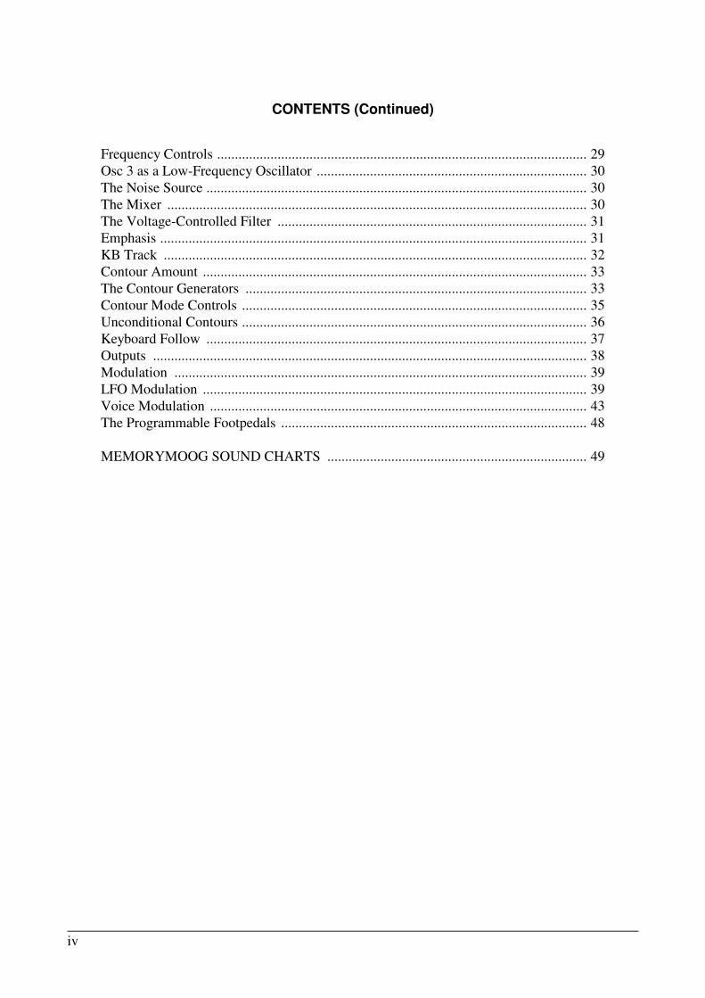
Frequency Controls ........................................................................................................ 29
Osc 3 as a Low-Frequency Oscillator ............................................................................ 30
The Noise Source ........................................................................................................... 30
The Mixer ...................................................................................................................... 30
The Voltage-Controlled Filter ....................................................................................... 31
Emphasis ........................................................................................................................ 31
KB Track ....................................................................................................................... 32
Contour Amount ............................................................................................................ 33
The Contour Generators ................................................................................................ 33
Contour Mode Controls ................................................................................................. 35
Unconditional Contours ................................................................................................. 36
Keyboard Follow ........................................................................................................... 37
Outputs .......................................................................................................................... 38
Modulation .................................................................................................................... 39
LFO Modulation ............................................................................................................ 39
Voice Modulation .......................................................................................................... 43
The Programmable Footpedals ...................................................................................... 48
MEMORYMOOG SOUND CHARTS ......................................................................... 49

1
INTRODUCTION
The Memorymoog is a voice-assignment polyphonic synthesizer with the ability to store up to
100 patches in computer memory. It has six independent voices, each containing three voltage-con-
trolled oscillators, a voltage-controlled 24dB/octave lowpass filter, two ADSR contour generators,
and extensive modulation facilities. This means that there are 18 oscillators, six filters, and 12 con-
tour generators in the unit. However, there is a single set of controls for those components, meaning
that their sound is programmed homophonically - each program governs each voice identically.
At the heart of the Memorymoog is the System Controller which gives you command over the
instrument's microprocessor. With the System Controller you can change programs, store patches,
change keyboard modes, use the cassette interface, alter arpeggiation mode, and set up program se-
quences. Learning to use the System Controller is the key to learning how to use the Memorymoog.
This manual is designed in sections, starting with a quick setup guide for those of you who are
in a hurry to quit reading and start playing. It tells you some dos and don'ts about setting up and ex-
plains what you'll need to know about the System Controller in order to get at the programs.
Section II is a reference guide designed to help answer any questions regarding specific features on
the Memorymoog. Section III is a step-by-step explanation of each set of controls for those of you
who aren't all that familiar with synthesis. It's designed to help clarify things that may seem vague in
Section II. The final section of the manual deals with service information and contains schematics
and maintenance details. A sound chart section is included that contains diagrams of all the factory
programs. Some blank panel diagrams are also provided for you to copy down your own patches.

2
SECTION I
SETTING UP
If you haven't bought a flight case for your Memorymoog, save the carton it came in in case you
have to arrange long distance transportation.
After unpacking your instrument, hook it up to a wall socket by first inserting the detachable
three-pronged cord into the back of the Memorymoog and then into the power outlet. Be sure that
the outlet is putting out the right amount of voltage.
110V = USA
220V = EUROPE
If you want to operate your Memorymoog on a voltage that differs from what's coming out of
the wall socket, i.e. 220 instead of 110 or 110 instead of 220, an authorized Moog service center can
set up your instrument to operate at the proper voltage.
Next hook any footpedals or switches you desire to use up to their respective inputs. Then con-
nect the audio output of the Memorymoog to an amplification system using either an XLR cable or
a 1/4" phone jack. A high quality amp is desirable due to the wide frequency range of the Memory-
moog. Also, note that different amps will make the programs sound different.
Turn the output volume of both the Memorymoog and the amp down to zero. Turn the Memory-
moog on and then turn the amp on. Bring the volume of the amp up to where you're used to setting
it. While holding down a note, bring the MASTER VOLUME control (at the upper right corner) up
until it's at a comfortable level.

3
SYSTEM CONTROLLER
PROGRAM
RECORDINTERLOCK
ENTER
1 2 3 A
4 5 6 B
7 8 9 C
0 D
EDIT
030 052}
SYSTEM CONTROLLER
PROGRAM
RECORDINTERLOCK
ENTER
1 2 3 A
4 5 6 B
7 8 9 C
0 D
1
6 TUNED
After you've turned the instrument on, let it warm up for about 10
minutes to allow the oscillators to stabilize. Then hit the AUTO TUNE
control in the upper left-hand corner. This will tune the Memorymoog's
18 oscillators. Notice that the SYSTEM CONTROLLER's Alphanu-
meric Display reads "6 TUNED" after the tuning cycle is complete, in-
dicating that all six voices have been tuned. If a number less than six
appears in the screen, it means that the system was unable to tune one
or more of the oscillators for some reason. Try hitting the AUTO
TUNE switch again if this occurs. If they still fail to tune, they can be
manually disabled. Refer to the Service Section of the manual for de-
tails.
CALLING UP PROGRAMS
When you first turn the Memorymoog on, program Number 1 will
appear in the PROGRAM DISPLAY window of the SYSTEM CON-
TROLLER. To change program numbers, hit any number from 0 to 99
followed by hitting the ENTER button on the Numeric Keyboard of the
SYSTEM CONTROLLER.
EDITING A SOUND
Changing or editing programs is very simple. If you want to alter
some aspect of any of the sounds supplied by the factory, all you have
to do is hit any of the switches (except those in the SYSTEM CON-
TROLLER) or hit any of the rotary controls (pots). You'll notice that
when you hit a switch the Alphanumeric Display will read "EDIT," and
when you turn a pot, six numbers appear in the display screen.
The group of three numbers on the left indicates the value of the pot as
it is in the program memory, and the group of three numbers on the
right indicates the current value of the pot.
Hitting the ENTER button will immediately restore the program
values.
SYSTEM CONTROLLER
PROGRAM
RECORDINTERLOCK
ENTER
1 2 3 A
4 5 6 B
7 8 9 C
0 D
1

4
SYSTEM CONTROLLER
PROGRAM
RECORDINTERLOCK
ENTER
1 2 3 A
4 5 6 B
7 8 9 C
0 D
17
B P1 26
CALLING UP AND STEPPING THROUGH PROGRAM SEQUENCES
To get into the PROGRAM SEQUENCE MODE hit PREFIX letter D, followed by any number
from 0 to 9, followed by ENTER. This gets you to one of the 10 PROGRAM SEQUENCES. What
will appear in the Alphanumeric Display looks like this:
The number in the PROGRAM DISPLAY is the first program of the PROGRAM SEQUENCE.
The B at the left of the screen indicates the beginning of the SEQUENCE. As you step through the
SEQUENCE, the number that appears in this spot indicates the previous program number. The cen-
ter of the display shows the PROGRAM SEQUENCE number, and the number to the right of the
screen is the program number next in line in the SEQUENCE.
To step through the PROGRAM SEQUENCE, use the A PREFIX switch to go forward and
the B PREFIX switch to go backward. You can also use PROGRAM ADVANCE and PROGRAM
BACKSTEP footswitches for these functions. (Note that the footswitches aren't supplied with the
instrument.)
Experimenting with the programs, editing them, and stepping through the PROGRAM SE-
QUENCES should keep you busy for at least a few minutes. It should also start generating questions
about other features on the instrument. Section II of the manual provides brief descriptions of all the
various functions of the Memorymoog, while Section III offers step-by-step explanations. From this
point, refer to those sections as the need arises.

5
1.0 KEYBOARD/PERFORMANCE CONTROLS.
1.1 AUTO TUNE.
Touching this switch causes the computer in the unit to tune the
18 oscillators. Tuning takes about 8 seconds. The instrument
will be "dead" for that period of time. The SYSTEM CON-
TROLLER's (3.0) Alphanumeric Display will show "TUNING"
when the switch is initially depressed, and it will show how
many voices have been tuned at the end of the tuning cycle.
1.2 TUNE.
Lets you fine tune the instrument over a range of ± 3 semitones.
This is a non-programmable control and will affect all voices
identically.
1.3 MONO.
This switch puts the instrument into the monophonic mode - it
will play only one key at a time. The number of voice cards you
control is variable from I up to 6, giving you control over from
1 to 18 oscillators. This is programmed by the SYSTEM CON-
TROLLER (3.0) and the MIXER section (7.0).
1.4 MULTIPLE TRIGGER.
When on, the keyboard triggers all contours when any new
keys are depressed. When off, new notes trigger only the as-
signed voice.
1.5 KB OUT.
KEYBOARD OUT controls the trigger and voltage outputs
from the EXTERNAL SYNTHESIZER OUTPUT section
(14.0). It's used when controlling an external synthesizer. When
on, the Memorymoog will control the external synthesizer.
1.6 GLIDE AMOUNT AND GLIDE ON/OFF.
The glide is both monophonic and polyphonic. When the in-
strument is in mono mode, a master glide circuit takes over for
the 6 separate glide circuits that work when it's in polyphonic
mode, and allows the instrument to glide in unison. Glide is
linear. Maximum glide time between the outer notes of the key-
board is about 10 seconds.
AUTO TUNE
TUNE
0
5
@ #
2 8
0 10
5
2 8
0 10PITCH BEND
AMOUNTMODULATION
AMOUNT
KB MODE HOLD ARPEGGIATOR
MONO MULTIPLETRIGGER
KB OUT
GLIDE ON/OFF
5
2 8
0 10GLIDE
SECTION II
This section of the Memorymoog manual is designed to answer questions about the function of each
control on the front and back panels of the instrument. It's a quick reference guide; more detailed
explanations will be found in the next portion of the manual.

6
1.7 KB MODE.
KEYBOARD MODE affects the priority of the
keyboard when it's in both mono and polyphonic
modes. In mono mode, the SYSTEM CONTROL-
LER (3.0) Alphanumeric Display shows either
"MONO 1, 2 or 3," depending on the mono mode
programmed. Mono 1 is last-note priority, Mono 2
is low-note priority, and Mono 3 is high-note pri-
ority. In polyphonic mode, the Alphanumeric Dis-
play will show either "POLY 1" (cyclic), "2" (cy-
clic with memory), "3" (reset to voice A), or "4"
(reset to voice A with memory). Voltages routed
to an external synth via the EXTERNAL SYN-
THESIZER OUTPUT (14.0) are affected by this
control.
1.8 HOLD.
Lets you build up chords and transpose them in
parallel motion from the keyboard. Holding a
chord and then pressing the HOLD button will
memorize the chord. Holding down the HOLD
button and then pressing notes on the keyboard
will let you build widely spaced chords. Releasing
the HOLD button memorizes the chord. The chord
can then be transposed from the last note you
played on the keyboard.
1.9 ARPEGGIATOR.
Continuously triggers note played on the key-
board. Rate is set by the LFO (5.0) speed. The
Clock can be overridden by an external trigger
source at the CLOCK IN (15.5) on the back panel.
The internal clock is reset by the keyboard so you
can always play in time. The Arpeggiator operates
in six different modes:
1) Plays back notes from bottom to top, un-
latched (notes stop when you lift off the key-
board).
2) Plays back notes from top to bottom, un-
latched.
3) Plays back notes from top to bottom, and then
from bottom to top, unlatched.
4) Plays back notes from bottom to top (latched).
The notes will continue if you lift your hands
off the keyboard.
5) Plays back notes from top to bottom, latched.
6) Plays back notes from top to bottom, and then
from bottom to top, latched.
1.10 PITCH BEND AMOUNT.
Lets you vary the maximum range of the
PITCH BENDING WHEEL (2.2) up to
± 1 octave. Note that this control is pro-
grammable.
1.11 MODULATION AMOUNT.
Sets a programmable initial modulation
amount. The MODULATION WHEEL
(2.3) adds to the amount set by this con-
trol.
AUTO TUNE
TUNE
0
5
@ #
2 8
0 10
5
2 8
0 10PITCH BEND
AMOUNTMODULATION
AMOUNT
KB MODE HOLD ARPEGGIATOR
MONO MULTIPLETRIGGER
KB OUT
GLIDE ON/OFF
5
2 8
0 10GLIDE
AUTO TUNE
TUNE
0
5
@ #
2 8
0 10
5
2 8
0 10PITCH BEND
AMOUNTMODULATION
AMOUNT
KB MODE HOLD ARPEGGIATOR
MONO MULTIPLETRIGGER
KB OUT
GLIDE ON/OFF
5
2 8
0 10GLIDE
7
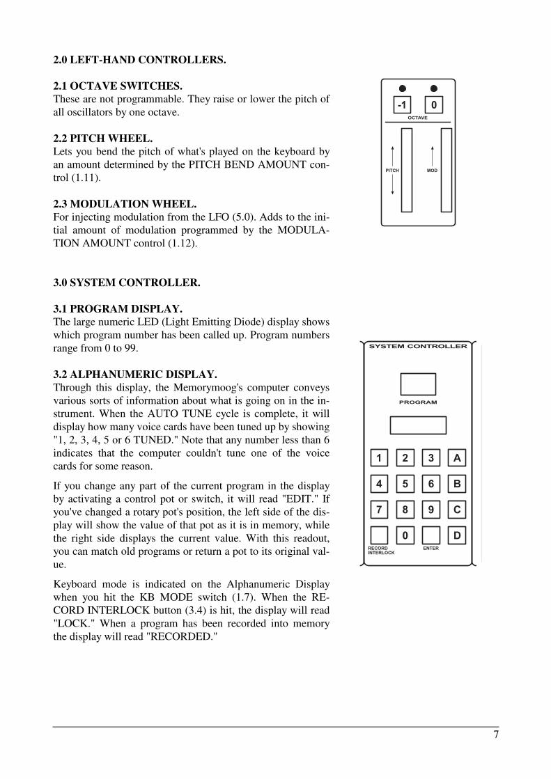
2.0 LEFT-HAND CONTROLLERS.
2.1 OCTAVE SWITCHES.
These are not programmable. They raise or lower the pitch of
all oscillators by one octave.
2.2 PITCH WHEEL.
Lets you bend the pitch of what's played on the keyboard by
an amount determined by the PITCH BEND AMOUNT con-
trol (1.11).
2.3 MODULATION WHEEL.
For injecting modulation from the LFO (5.0). Adds to the ini-
tial amount of modulation programmed by the MODULA-
TION AMOUNT control (1.12).
3.0 SYSTEM CONTROLLER.
3.1 PROGRAM DISPLAY.
The large numeric LED (Light Emitting Diode) display shows
which program number has been called up. Program numbers
range from 0 to 99.
3.2 ALPHANUMERIC DISPLAY.
Through this display, the Memorymoog's computer conveys
various sorts of information about what is going on in the in-
strument. When the AUTO TUNE cycle is complete, it will
display how many voice cards have been tuned up by showing
"1, 2, 3, 4, 5 or 6 TUNED." Note that any number less than 6
indicates that the computer couldn't tune one of the voice
cards for some reason.
If you change any part of the current program in the display
by activating a control pot or switch, it will read "EDIT." If
you've changed a rotary pot's position, the left side of the dis-
play will show the value of that pot as it is in memory, while
the right side displays the current value. With this readout,
you can match old programs or return a pot to its original val-
ue.
Keyboard mode is indicated on the Alphanumeric Display
when you hit the KB MODE switch (1.7). When the RE-
CORD INTERLOCK button (3.4) is hit, the display will read
"LOCK." When a program has been recorded into memory
the display will read "RECORDED."
SYSTEM CONTROLLER
PROGRAM
RECORDINTERLOCK
ENTER
1 2 3 A
4 5 6 B
7 8 9 C
0 D
0-1
PITCH MOD
OCTAVE

8
3.6 PREFIX BUTTONS.
PREFIX A advances programs stored in the PROGRAM SEQUENCE MODE (see below). Also
advances program number by one in normal operating mode.
PREFIX B steps in reverse through the programs in the PROGRAM SEQUENCE MODE (see be-
low). Backsteps program number by one in normal operating mode.
PREFIX C1 (hit C, hit 1, hit ENTER) saves programs onto cassette tape (for more information on
this procedure see the next section of the manual).
PREFIX C2 (hit C, hit 2, hit ENTER) loads programs from cassette tape into the Memorymoog's
memory.
PREFIX C3 (hit C, hit 3, hit ENTER) verifies correct loading of programs when putting programs
from the Memorymoog onto cassette tape.
PREFIX C4 is used for defeating voices that aren't tuning up for whatever reason. See text in next
section of the manual for details.
3.3 NUMERIC KEYBOARD.
This calculator-type keyboard is used for calling up programs and other control functions. You do
this by hitting one or two numbers (from 0 to 99) and then pressing the ENTER button.
3.4 RECORD INTERLOCK.
This switch is used to temporarily lock the front panel settings in memory. By hitting LOCK, the
Alphanumeric Display (3.2) will read "LOCK," indicating that the current panel settings are tempo-
rarily locked, and turning pots or hitting switches will have no effect. This allows you to call up an-
other patch from memory (by hitting a number and pressing ENTER) without losing the locked
patch. Hitting the LOCK switch after you've called up another patch will bring up the locked patch.
This is useful for checking edited patches against the original version.
3.5 STORING A PATCH IN MEMORY.
This is done by holding the LOCK button (3.4)
down and hitting the ENTER button (see 3.3). This
loads whatever is currently shown on the front panel
into the memory position called up in the Program
Display (3.1). Note that recording a patch is impos-
sible if the Memorymoog is "write disabled," mean-
ing that a protect function against storing unwanted
information in memory is on. To turn the protect
function off and on, you must know the four-digit
security code (see Section III). Attempting to store a
patch in memory when the disable feature is on will
cause the Alphanumeric Display (3.2) to read
"DISABLED." When a patch has been successfully
written into a memory position the Alphanumeric
Display will read "RECORDED."
SYSTEM CONTROLLER
PROGRAM
RECORDINTERLOCK
ENTER
1 2 3 A
4 5 6 B
7 8 9 C
0 D

9
PREFIX C9 makes the front panel live. The Alpha-
numeric Display (3.2) will read "LIVE PNL" when
you hit C, hit 9, hit ENTER. In this state, the front
panel controls override the memory settings.
PREFIX C0 flashes all the LEDs. This is another
service function to check if all the LEDs work. Hit-
ting any switch turns the function off.
PREFIXES D0 to D9 call up PROGRAM SE-
QUENCES. These are chains of up to 20 programs,
each arranged in some predetermined order. To call
one up hit D, hit a number from 0 to 9, and hit EN-
TER. To load a PROGRAM SEQUENCE, hit D, hit
D again, hit a number from 0 to 9 and hit ENTER to
get into PROGRAM SEQUENCE LOADING
MODE. Then to enter programs, hit the program
number, hit ENTER, hit A (ADVANCE switch) or
B (BACKSTEP switch). Repeat until you've loaded
all the programs you require. The loading mode will
stop after 10 programs are loaded. You can also use
the ADVANCE and BACKSTEP footswitches (15.3
and 15.4) to step forward and backward in the PRO-
GRAM SEQUENCE.
PREFIX C5 tunes all oscillators to unison, regardless of front panel settings.
PREFIXES C6 and C7 are electronic tuning aids for service technicians.
PREFIX C8 displays current memory status, ENABLED or DISABLED in the Alphanumeric Dis-
play (3.2). The unit powers up with the memory disabled so that you can't accidentally record a
patch and you can't use the cassette interface functions of PREFIXES C1, 2, and 3. To enable the
memory store function, hit C8 followed by the four-digit security code (see Section III). Hitting the
letter C after entering C8 tells the instrument that you want to change the security code. Do this by
entering the old four-digit code (the code of instruments fresh from the factory is 0000); the display
will read "NEW CODE" or "BAD CODE" depending on if you have it right or not. If the old code
is correct, you may then enter any new four-digit code.
SYSTEM CONTROLLER
PROGRAM
RECORDINTERLOCK
ENTER
1 2 3 A
4 5 6 B
7 8 9 C
0 D

10
PITCH VOLUME
FOOTPEDALS
AMOUNT 1
AMOUNT 2
5
2 8
0 10
MOD AMT OSC 2
5
2 8
0 10
FILTER
MODULATION
¤
LFO MODULATION5
.5 25
RATE (HZ)
.1 100� � � S-H
OSC 1FREQ
OSC 2FREQ
OSC 3FREQ
PW 1 PW 2 PW 3 Filter
5
2 8
DESTINATION
0 10
5
2 8
OSC 3
0 10
VOICE MODULATION
CONTOUREDOSC 3 AMOUNT
INVERT
OSC 1FREQ
OSC 2FREQ
PW 1 PW 2 FILTER
FILTER CONTOUR
4.0 FOOTPEDALS.
4.1 AMOUNT 1, PITCH, VOLUME, FILTER.
The AMOUNT knob controls the overall range of footpedal num-
ber 1 which can be routed to control the pitch of all the oscillators,
the volume, and the filter's cutoff frequency. Functions are pro-
grammable.
4.2 AMOUNT 2, MOD AMT, OSC 2.
Determines the range of a second voltage pedal which can be
routed to control the amount of modulation and/or the frequency of
the second oscillator.
NOTE: Footpedals are not supplied with the instrument. The in-
puts on the back panel (13.0) will use any voltage input that ranges
from 0 to 5 volts. If you plug in just one pedal, the input will cross-
couple so that one footpedal will control whatever is called up on
either PEDAL 1 or PEDAL 2's programs.
5.0 LFO MODULATION.
The amount of modulation is controlled by the MODULATION
AMOUNT knob (1.12) and the MODULATION WHEEL (2.3).
5.1 RATE (HZ).
Controls the LFO frequency. Variable from
.1 Hz to 100Hz.
5.2 WAVESHAPE SELECTION.
Five switches to the right of the RATE (5.1)
knob for selecting triangle, positive-going
saw-tooth, negative-going sawtooth, square,
or sample-and-hold waveshapes for the low
frequency oscillator. Selecting one wave-
shape excludes the others; waveshapes can't
be intermixed.
5.3 DESTINATION SWITCHES.
The output of the LFO can be routed to seven
places. It can be used to modulate the fre-
quencies of oscillator 1 (OSC 1), oscillator 2
(OSC 2), oscillator 3 (OSC 3), the pulse
width of oscillator 1 (PW 1), the pulse width
of oscillator 2 (PW 2), the pulse width of os-
cillator 3 (PW 3), and/or the filter's cutoff fre-
quency.

11
MODULATION
¤
LFO MODULATION5
.5 25
RATE (HZ)
.1 100� � � S-H
OSC 1FREQ
OSC 2FREQ
OSC 3FREQ
PW 1 PW 2 PW 3 Filter
5
2 8
DESTINATION
0 10
5
2 8
OSC 3
0 10
VOICE MODULATION
CONTOUREDOSC 3 AMOUNT
INVERT
OSC 1FREQ
OSC 2FREQ
PW 1 PW 2 FILTER
FILTER CONTOUR
5.4 VOICE MODULATION.
The source of this modulation is selectable from either the filter's contour generator or the third os-
cillator. These affect each voice independently. Voice Modulation is independent of the LFO Modu-
lation (5.0).
5.5 OSC 3.
Controls the amount of modulation from oscil-
lator 3.
5.6 FILTER CONTOUR.
Controls the amount of modulation from the
filter's contour generator.
5.7 CONTOURED OSC 3 AMOUNT.
When switched on allows the filter's contour
generator to shape the amount of modulation
coming from oscillator three. This is useful for
creating modulation effects that vary with
time.
5.8 INVERT.
Inverts the filter contour as it's applied to the
CONTOURED OSC 3 AMOUNT (5.7) and
inverts the output of OSC 3 (6.0).
5.9 DESTINATION SWITCHES.
Voice Modulation can be routed to five places
using this set of switches: the frequency of os-
cillator 1 (OSC 1 FREQ), the frequency of os-
cillator 2 (OSC 2 FREQ), the pulse width of
oscillator 1 (PW 1), the pulse width of oscilla-
tor 2 (PW 2), and/or the filter's cutoff fre-
quency (FILTER).
12
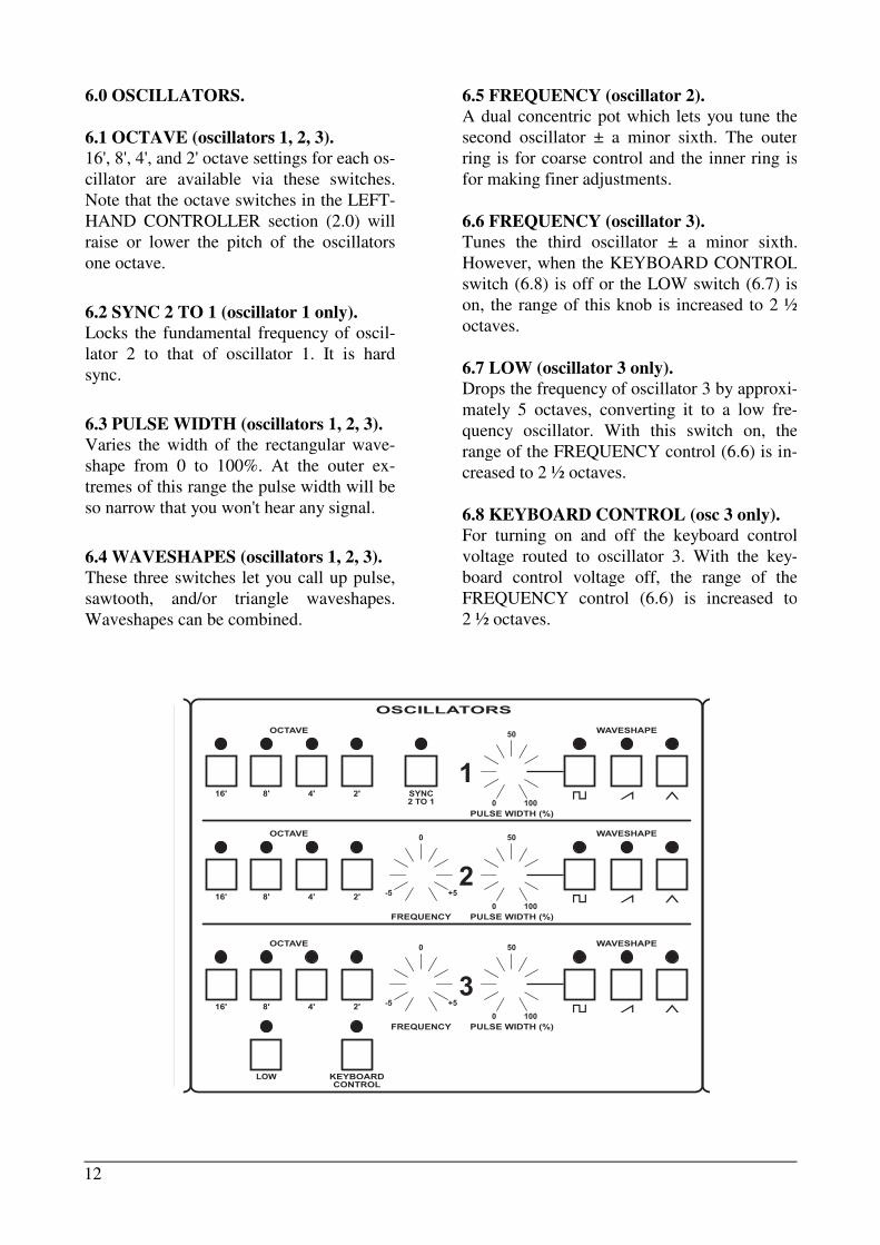
6.5 FREQUENCY (oscillator 2).
A dual concentric pot which lets you tune the
second oscillator ± a minor sixth. The outer
ring is for coarse control and the inner ring is
for making finer adjustments.
6.6 FREQUENCY (oscillator 3).
Tunes the third oscillator ± a minor sixth.
However, when the KEYBOARD CONTROL
switch (6.8) is off or the LOW switch (6.7) is
on, the range of this knob is increased to 2 ½
octaves.
6.7 LOW (oscillator 3 only).
Drops the frequency of oscillator 3 by approxi-
mately 5 octaves, converting it to a low fre-
quency oscillator. With this switch on, the
range of the FREQUENCY control (6.6) is in-
creased to 2 ½ octaves.
6.8 KEYBOARD CONTROL (osc 3 only).
For turning on and off the keyboard control
voltage routed to oscillator 3. With the key-
board control voltage off, the range of the
FREQUENCY control (6.6) is increased to
2 ½ octaves.
6.0 OSCILLATORS.
6.1 OCTAVE (oscillators 1, 2, 3).
16', 8', 4', and 2' octave settings for each os-
cillator are available via these switches.
Note that the octave switches in the LEFT-
HAND CONTROLLER section (2.0) will
raise or lower the pitch of the oscillators
one octave.
6.2 SYNC 2 TO 1 (oscillator 1 only).
Locks the fundamental frequency of oscil-
lator 2 to that of oscillator 1. It is hard
sync.
6.3 PULSE WIDTH (oscillators 1, 2, 3).
Varies the width of the rectangular wave-
shape from 0 to 100%. At the outer ex-
tremes of this range the pulse width will be
so narrow that you won't hear any signal.
6.4 WAVESHAPES (oscillators 1, 2, 3).
These three switches let you call up pulse,
sawtooth, and/or triangle waveshapes.
Waveshapes can be combined.
OSCILLATORS
0
-5 +5
50
0 100
16' 8' 4' 2'
PULSE WIDTH (%)
1� � ¤
WAVESHAPE
SYNC2 TO 1
OCTAVE
50
0 100
16' 8' 4' 2'
PULSE WIDTH (%)
2� � ¤
WAVESHAPEOCTAVE
FREQUENCY
0
-5 +5
50
0 100
16' 8' 4' 2'
PULSE WIDTH (%)
3� � ¤
WAVESHAPEOCTAVE
FREQUENCY
LOW KEYBOARDCONTROL

13
MIXER
LEVEL
5
2 8
0 10
LEVEL
5
2 8
0 10
LEVEL
5
2 8
0 10
NOISE
5
2 8
0 10
VOLTAGE CONTROLLED FILTER
1/3 2/3
KB TRACK
VOLTAGE CONTROLLED AMPLIFIER
0
-5 5
CUTOFF
-3 3
5
0 10
2 8
CONTOUR AMOUNT
1
1 MSEC 10 SEC
ATTACK
700
400
1.5
3
100
10 9
6
2
2 MSEC 20 SEC
DECAY
1.4
800
3
6
200
20 18
12
RETURNTO ZERO
UNCONDITIONALCONTOUR
KEYBOARDFOLLOW
RELEASE
5
0 10
2 8
EMPHASIS
5
0 10
2 8
SUSTAIN
2
2 MSEC 20 SEC
1.4
800
3
6
200
20 18
12
RELEASE
1
1 MSEC 10 SEC
ATTACK
700
400
1.5
3
100
10 9
6
2
2 MSEC 20 SEC
DECAY
1.4
800
3
6
200
20 18
12
5
0 10
2 8
SUSTAIN
2
2 MSEC 20 SEC
1.4
800
3
6
200
20 18
12
RELEASE
7.0 MIXER.
Four level controls for adjusting the relative volumes of the three os-
cillators and a pink noise source as they feed into the filter. Note that
beyond a setting of 4 or 5, these controls cause the signals to clip (dis-
tort). This gives a little more punch to a sound where desired. It also
turns the triangle waves into sine waves. At a setting of 10 you will
hear some intermodulation distortion.
8.0 VOLTAGE CONTROLLED FILTER.
The Voltage Controlled Filter is the patented Moog 24db/octave low-
pass filter.
8.1 KB TRACK.
Varies the amount of voltage from the keyboard that controls the filter
cutoff frequency. You can select either } of the keyboard voltage, { of
the keyboard voltage, all of the keyboard voltage (both switches on),
or no keyboard voltage (both switches off).
8.2 CUTOFF.
Controls the cutoff frequency of the filter.
8.3 EMPHASIS.
Controls the degree of filter resonance. Oscillation begins at a little
past a setting of 7.
8.4 CONTOUR AMOUNT.
Controls the amount of voltage from the
FILTER CONTOUR GENERATOR (8.5)
that is applied to the cutoff frequency.
8.5 FILTER CONTOUR GENERATOR.
8.6 ATTACK.
Varies the attack time from 1 millisecond to
10 seconds.
8.7 DECAY.
Variable from 2 milliseconds to 20 seconds.
8.8 SUSTAIN.
Varies the sustain level of the filter contour.
8.9 RELEASE.
Adjustable from 2 milliseconds to 20 sec-
onds. The RELEASE SWITCH (10.4) and/
or the RELEASE FOOTSWITCH (15.1)
turn the release portion of the contour on
and off.

14
VOLTAGE CONTROLLED FILTER
1/3 2/3
KB TRACK
VOLTAGE CONTROLLED AMPLIFIER
0
-5 5
CUTOFF
-3 3
5
0 10
2 8
CONTOUR AMOUNT
1
1 MSEC 10 SEC
ATTACK
700
400
1.5
3
100
10 9
6
2
2 MSEC 20 SEC
DECAY
1.4
800
3
6
200
20 18
12
RETURNTO ZERO
UNCONDITIONALCONTOUR
KEYBOARDFOLLOW
RELEASE
5
0 10
2 8
EMPHASIS
5
0 10
2 8
SUSTAIN
2
2 MSEC 20 SEC
1.4
800
3
6
200
20 18
12
RELEASE
1
1 MSEC 10 SEC
ATTACK
700
400
1.5
3
100
10 9
6
2
2 MSEC 20 SEC
DECAY
1.4
800
3
6
200
20 18
12
5
0 10
2 8
SUSTAIN
2
2 MSEC 20 SEC
1.4
800
3
6
200
20 18
12
RELEASE
9.0 VOLTAGE CONTROLLED AMPLIFIER.
An ADSR contour generator controls the VCA.
9.1 ATTACK.
Same as section 8.6.
9.2 DECAY.
Same as section 8.7.
9.3 SUSTAIN.
Same as section 8.8.
9.4 RELEASE.
Same as section 8.9.
10.0 CONTOUR CONTROLS.
This set of four switches affects both Contour
Generators.
10.1 RETURN TO ZERO.
Normally, the Contour Generators, if retrig-
gered during the attack segment, start from the
existing voltage level. With this switch on, the
attack segment will always reset to zero volts.
10.2 UNCONDITIONAL CONTOUR.
With this switch off, the Contour Generators
will go into their release states (if the RE-
LEASE SWITCH [10.4] is on or the RELEASE
FOOT SWITCH [15.1] is depressed) only when
you let up on a key. With the switch on, when
you let up on a note, the Contour Generators
will go through their entire attack phase and
then jump immediately into the release state.
10.3 KEYBOARD FOLLOW.
When this switch is on, the voltage from the key
board varies the attack, decay and release times
of the Contour Generators. The lower you play,
the longer the times; the higher you play, the
shorter the times.
10.4 RELEASE.
Turns the release segment of the Contour Gen-
erators on and off. This control interacts with
the RELEASE FOOTSWITCH (15.1).

15
OUTPUTS
MASTERVOLUME
5
2 8
0 10
VOLUME
5
2 8
0 10
5
2 8
0 10
PROGRAMMABLE
VOLUME
HEADPHONE
12.0 HI-LEVEL AUDIO OUTPUT.
12.1 BALANCED.
A transformer-balanced 600 ohm output.
12.2 UNBALANCED.
An unbalanced low-impedance output.
13.0 FOOTPEDAL IN.
13.1
Input for a 5-volt voltage pedal controller
whose function is programmed on the front
panel (see 4.0).
13.2 Input for a 5-volt voltage pedal controller
whose function is preprogrammed on the front
panel (see 4.0).
Note that inputs 1 and 2 (13.1 and 13.2) are
crosscoupled; if you have only one pedal in,
that pedal's voltage will be applied to both
front panel pedal sections.
11.0 OUTPUTS.
11.1 MASTER VOLUME.
A non-programmable volume control.
11.2 PROGRAMMABLE VOLUME.
Used for matching volume levels between programs.
11.3 HEADPHONE VOLUME.
A non-programmable volume control that's independent of
the MASTER VOLUME control (11.1 ). It adjusts the level
of the stereo headphone output.
THE BACK PANEL
BACK PANEL

16
14.0 EXTERNAL SYNTHESIZER OUT.
14.1 CONTROL VOLT 1 VOLT/OCT.
A 1 volt-per-octave (± 10%) output for con-
trolling an external synthesizer or synthesizer
accessory. Range and scale trimmers for tuning
the output to an external synthesizer are acces-
sible through the rear panel.
14.2 V-GATE 0 - 15V.
A voltage gate output with a level of from 0 to
15 volts for interfacing with instruments which
accept voltage gates.
14.3 S-TRIG 15V TO 0.
A switch trigger output with a range of 15
volts to 0 volts. For interfacing to instruments
with switch trigger inputs.
15.0 FOOTSWITCH IN.
15.1 RELEASE.
Accepts a switch input for turning the release
portion of the Contour Generators on and off
(see 10.4). With the RELEASE switch on the
front panel on, depressing the RELEASE
FOOTSWITCH will turn the RELEASE
switch on the panel off. At that point, the RE-
LEASE FOOTSWITCH will act as a SUS-
TAIN PEDAL would on a piano: pressed
down, the RELEASE function of the CON-
TOUR GENERATORS (8.5 and 9.0) will be
on; let up, the RELEASE function of the
CONTOUR GENERATORS will be off.
15.2 HOLD.
A switch input for turning the HOLD function
(1.8) on and off.
15.3 PROGRAM ADVANCE.
A switch input for advancing through the
PROGRAM SEQUENCES (3.7).
15.4 PROGRAM BACKSTEP.
A switch for stepping through the PROGRAM
SEQUENCES (3.7) in reverse order.
15.5 GLIDE.
Turns the front panel GLIDE switch on or off.
15.6 CLOCK IN.
Replaces the internal clock from the LFO (5.0)
with an external clock.
16.0 CASSETTE INTERFACE.
Connections are made from the three jacks to a
cassette recorder for transfer of memory con-
tents to and from tape.
17.0 POWER ON/OFF.
Turns the Memorymoog on and off.
18.0 POWERCORD.
A detachable cord is supplied with your instru-
ment. Be careful to grasp it by the plug when
taking it out of an electrical outlet.
BACK PANEL

17
SYSTEM CONTROLLER
PROGRAM
RECORDINTERLOCK
ENTER
1 2 3 A
4 5 6 B
7 8 9 C
0 D
PROGRAMDISPLAY
SYSTEM CONTROLLER
PROGRAM
RECORDINTERLOCK
ENTER
1 2 3 A
4 5 6 B
7 8 9 C
0 D
NUMERICKEYBOARD
ENTERSWITCH
SYSTEM CONTROLLER
PROGRAM
RECORDINTERLOCK
ENTER
1 2 3 A
4 5 6 B
7 8 9 C
0 D
ALPHA-NUMERICDISPLAY
SECTION III
THE SYSTEM CONTROLLER
The SYSTEM CONTROLLER is the heart of the
Memorymoog. Of all the front panel controls, you'll find
yourself using the SYSTEM CONTROLLER most fre-
quently. It is used to store and recall patches, set up key-
board modes, set up arpeggiation modes, control program
sequencing, access the cassette interface, and many other
present and future functions.
When you first power up the Memorymoog, you'll no-
tice that the number 1 appears in the large LED display la-
beled PROGRAM. This tells you that program #1 is called
up and ready to play. This window, the PROGRAM DIS-
PLAY (3.1), will always show which program is currently
called up and ready to play, or which program is about to
be entered.
As discussed in the quick setup guide, let your instru-
ment warm up for about 10 minutes, press the AUTO
TUNE switch (1.1), and let the instrument tune itself be-
fore playing. After the AUTO TUNE routine is complete,
program #1 will appear again in the PROGRAM DIS-
PLAY and the appropriate LEDs for program #1 will light
up. (Should you need to tune the instrument at any time
after it's been warmed up, the computer will always re-
member the state of the panel controls just prior to the tun-
ing routine and return to it.) The Alphanumeric Display
(3.2) will read "6 TUNED" indicating that all six voice
cards have been tuned successfully. If any number less
than six appears you should hit AUTO TUNE again. If all
six voice cards still fail to tune, try turning the instrument
off for a moment. Then turn it on again and hit the AUTO
TUNE switch. If all this fails, contact an authorized serv-
ice center or call our factory service center for assistance.
CALLING UP PROGRAMS
To call up a program, hit any desired number from 0
to 99 on the Numeric Keyboard (3.3) and follow it by
pressing the ENTER switch.
The ENTER switch must be pressed in order for a new
program to replace the one that is currently called up.
The new number appears on the display immediately,
but the new program is not active until the ENTER
switch is pressed.

18
SYSTEM CONTROLLER
PROGRAM
RECORDINTERLOCK
ENTER
1 2 3 A
4 5 6 B
7 8 9 C
0 D
SYSTEM CONTROLLER
PROGRAM
RECORDINTERLOCK
ENTER
1 2 3 A
4 5 6 B
7 8 9 C
0 D
LIVE PNL
RECORDING PROGRAMSIn order to record your own patches into the program memory you have to ENABLE the record
function. To do this, press PREFIX BUTTON C (3.6), hit 8, and hit ENTER. This will display the
status of the instrument. The Alphanumeric Display will read "DISABLED" or "ENABLED."
Now you must enter a four-digit security code (when each instrument is shipped, the code is 0000).
If you enter the wrong code, the display reads "BAD CODE" and returns to normal operation. If you
enter the correct code, the instrument shows the updated status (ENABLED or DISABLED) and re-
turns to normal operation. To change the code, hit C, hit 8, hit ENTER, then hit C again; the instru-
ment assumes you want to change the security code and displays "OLD CODE." You enter the ex-
isting code; if the code is incorrect the display reads "BAD CODE," and operation returns to nor-
mal. If the code is correct, the display reads "NEW CODE," and you enter any new four-digit code
number, followed by ENTER. A convenient code number is the last four digits of your telephone
number.
MEMORY ENABLE/DISABLE PROCEDURE
PRESS C
PRESS 8
PRESS ENTER = ENABLED OR DISABLED
MEMORY RECORD FUNCTION
Once you've ENABLED the memory, you're ready to store patches. The memory position you
decide on should be one that has a patch you don't want, since once you record another patch over it,
it's gone (unless, of course, you've stored it on cassette tape using the procedure explained a little
later).
There are two ways of arriving at a patch you like: setting one up from scratch (starting from a
"live panel"), or editing (changing) a prerecorded patch. To set up a live panel – one where all the
controls are active, overriding the memory values – hit PREFIX C, number 9, and ENTER.
LIVE FRONT PANEL
HIT C
HIT 9
HIT ENTER = LIVE PANEL

19
SYSTEM CONTROLLER
PROGRAM
RECORDINTERLOCK
ENTER
1 2 3 A
4 5 6 B
7 8 9 C
0 D
To edit or change any preset program, change any of the parameters by moving a pot or pushing
a switch. When you hit a switch, you'll notice the Alphanumeric Display will read "EDIT" to tell
you you've changed a parameter of the program. If you turn a pot, you'll see six numbers appear in
the Alphanumeric Display. The three on the left of the screen tell you what the control's value is in
memory, and the three on the right tell you the current value of the control. Note that edit changes
aren't permanent changes in the memory. Hitting the ENTER switch at any time while you're editing
a sound will immediately restore the patch to its original preprogrammed state. To hear this effect,
call up a familiar patch. Make a few edits - changing the CUTOFF of the FILTER, or change the oc-
tave settings of the oscillators. Now hit the ENTER switch again. Everything will jump back to the
way it was before you edited the sound.
RECORDING A PATCH
HIT RECORD INTERLOCK AND HOLD IT
HIT ENTER = RECORD A PATCH (EITHER
FROM A "LIVE PANEL" OR
FROM HAVING EDITED
A PREPROGRAMMED PATCH)
Suppose you want to record a new patch. What do you do? There are two ways to go about it:
1) Find the place you want to put it; punch that program number. Hit C, hit 9, hit ENTER to put the
panel into a live state. Set up the patch the way you want it, then hit the RECORD INTERLOCK
switch. This locks all the front panel controls so that moving them will have no effect at all on the
patch as long as the RECORD INTERLOCK switch doesn't get hit again, cancelling the LOCK.
Then while holding down the RECORD INTERLOCK switch, press the ENTER button. The Al-
phanumeric Display will read either "RECORDED" to indicate a successful recording, or
"DISABLED" to indicate that the record function of the memory is off and must be turned on to re-
cord a patch in memory.
2) The other method of recording a patch involves recording edited versions of programs using the
RECORD INTERLOCK switch to freeze them in temporary memory, so they can be moved to other
locations or checked against the original patch. Edit a patch, hit the RECORD INTERLOCK switch
to put the edited patch in temporary memory and freeze the front panel controls. Now if you hit the
ENTER switch (don't hold the RECORD INTERLOCK button down!) you'll reinstate the original
preset program. Hitting the RECORD INTERLOCK switch will bring back the edited version of the
patch. This lets you do A/B comparisons between patches.
Note that you aren't limited to A/B comparisons between the edited patch and its original form.
All you have to do is hit the RECORD INTERLOCK switch, putting the edited or live panel patch
into temporary memory, and call up the program you want to check it against (hit a number fol-
lowed by ENTER). To get the LOCKED setting back, hit the RECORD INTERLOCK switch again.
If you decide you want to record the LOCKED setting into a memory position, hold the RECORD
INTERLOCK switch down and hit the ENTER button. Be sure the PROGRAM DISPLAY is show-
ing the desired program number; otherwise you'll erase a patch you may have wanted to save.

20
PROGRAM SEQUENCES
The D PREFIX switch is used to call up and record PROGRAM SEQUENCES. There are 10
PROGRAM SEQUENCES in the Memorymoog. These are chains of up to 20 programs which the
user determines.
To call up a PROGRAM SEQUENCE hit D, the PROGRAM SEQUENCE number (any num-
ber from 0 to 9), and hit ENTER. What you will see in the PROGRAM DISPLAY is the first pro-
gram in the PROGRAM SEQUENCE. The Alphanumeric Display will look like this:
PROGRAM SEQUENCE DISPLAY
There are two possible methods for stepping forward or backward through the programs in a PRO-
GRAM SEQUENCE. You can use the A and B PREFIX switches on the Numeric Keyboard (see di-
agram above) or you can use ADVANCE and BACKSTEP footswitches (not supplied with the in-
strument, but available as Moog accessory number 1122).
The A PREFIX switch advances (steps forward into) the PROGRAM SEQUENCE, while the B
PREFIX switch backsteps through the PROGRAM SEQUENCE.
LOADING YOUR OWN PROGRAM SEQUENCE
This process is fairly simple, but may require some practice until you get the hang of it. The
procedure is as follows:
Hit D to get yourself into the PROGRAM SEQUENCE MODE. Then hit D again, putting you into
LOAD MODE (an L will appear in the Alphanumeric Display). Hit a number from 0 to 9 for the
number of the PROGRAM SEQUENCE you wish to load, and then hit ENTER.
To load in the first program in the PROGRAM SEQUENCE, hit the number of the program, hit
ENTER, and hit A. This will load the first program into the PROGRAM SEQUENCE. Repeat until
you've either filled up the PROGRAM SEQUENCE (20 programs maximum for each SE-
QUENCE), or until you've got all the programs you desire to the maximum number of 20. (Putting
less than 20 programs in a chain is possible.)

21
HIT D
HIT D
HIT A NUMBER FROM 0 TO 9
HIT ENTER = LOADING MODE
HIT #
HIT ENTER
HIT A
HIT ENTER = LOAD A PROGRAM FORWARD INTO PROGRAM SEQUENCE
HIT #
HIT ENTER
HIT B
HIT ENTER = LOAD A PROGRAM BACKWARD INTO PROGRAM SEQUENCE
Should you decide that you want to replace a program in the SEQUENCE, you can step through
the chain to the program you want to replace and repeat the steps above for recording a program into
the SEQUENCE. This will update the PROGRAM SEQUENCE.
Using the B PREFIX switch in place of the A PREFIX switch in the above loading procedure
will cause the programs to be loaded into the previous position rather than in the position shown,
Here's a hypothetical PROGRAM SEQUENCE and the procedure for loading it for you to prac-
tice on:
The SEQUENCE we want runs programs 10, 20, 30, 40, 50, 60, 70. To load it proceed thus:
1) Hit D
2) Hit D again
3) Hit 0 = load PROGRAM SEQUENCE 0.
4) Hit 10
5) Hit ENTER
6) Hit A = load first program into first position of SEQUENCE 0.
7) Hit 20
8) Hit ENTER
9) Hit A = load second program into second position of SEQUENCE 0.
CONTINUE until you've loaded all the programs into the SEQUENCE. To stop loading PRO-
GRAM SEQUENCE 0, hit D again. This will get you out of PROGRAM SEQUENCE MODE. Hit-
ting D, 0, ENTER will recall PROGRAM SEQUENCE 0. Step through it to see if it's correct. The
SEQUENCE should run 10, 20, 30, 40, 50, 60, 70. If it doesn't, try to correct your mistake. Correct-
ing mistakes is a great way to familiarize yourself with the operation of the PROGRAM SE-
QUENCE MODE.
Note that if you should need to run more than 20 programs in a PROGRAM SEQUENCE, the
PROGRAM SEQUENCE automatically jumps to the next PROGRAM SEQUENCE number when
it has reached the end of a SEQUENCE. Step through to the end of PROGRAM SEQUENCE 0 (an
E will appear in the right side of the Alphanumeric Display) and keep going. It will run to PRO-
GRAM SEQUENCE 1. If you step through PROGRAM SEQUENCE 0 backwards (using either the
B PREFIX switch or the BACKSTEP footswitch) it will jump to PROGRAM SEQUENCE 9.

22
(SCALE)(RANGE)
SIGNAL IN (MIC OR AUX).140" MINI PLUG (3.5mm)
SIGNAL OUT (EAR PHONE).140" MINI PLUG (3.5mm)
MOTOR START/STOP.097" MICRO MINI PLUG (2.5mm)
(TO TAPE) CASSETTE1/4" PHONE PLUG(6.35mm)
(FROM TAPE) CASSETTE1/4" PHONE PLUG(6.35mm)
(REMOTE) CASSETTE1/4" PHONE PLUG(6.35mm)
THE CASSETTE INTERFACE
This is used to store information from the memory onto cassette tapes, expanding your library
of patches beyond the 100 that the Memorymoog will hold. To access the interface, it's necessary to
connect the cassette properly.
Connect the Memorymoog TO TAPE output to the MIC level input of the recorder. (Use only one
channel of a stereo recorder.) Connect the Memorymoog FROM TAPE input to the EARPHONE
(or line level) output of the recorder and, where applicable, connect the Memorymoog REMOTE
jack to the REMOTE or START/STOP input of the recorder. If your recorder is not so equipped,
start/ stop must be done manually.
If you don't have a small cassette tape recorder with automatic level control, there is a leader
signal at the front of the cassette save function which you can use to set the level of your recorder. It
should be set at around ± 3 on the VU meter to ensure sufficient level.
To save programs onto tape, hit PREFIX C, press 1, press ENTER. This starts the cassette save
operation, which takes about 30 seconds. When saving to tape, your instrument is inoperative.
When it's complete, the Alphanumeric Display will read "SAVED."
To verify that saving took place correctly, rewind the tape and press PREFIX C, hit 3, hit EN-
TER, and start the tape. When the tape has been completed, the Alphanumeric Display will read
"VERIFIED" if the tape has been made properly. It will read "ERROR" if there's a problem. If the
playback volume is too low, the Display will read "VOL LOW."
To load programs from a cassette tape, press PREFIX C, hit 2, hit ENTER. When the tape has
been completed, the Alphanumeric Display will read "LOADED" if there wasn't any problem. It
will read "VOL LOW" if the playback volume is too low, and it will read "ERROR" if there's some
other problem. Generally speaking, you should always verify a tape before you try to load it.
INTERFACING THE MEMORYMOOG TO A MONOPHONIC SYNTH
It's possible to control an external monophonic synthesizer using the INTERFACE jacks (14.0) pro-
vided on the Memorymoog's back panel.
BACK PANEL

23
AUTO TUNE
TUNE
0
5
@ #
2 8
0 10
5
2 8
0 10PITCH BEND
AMOUNTMODULATION
AMOUNT
KB MODE HOLD ARPEGGIATOR
MONO MULTIPLETRIGGER
KB OUT
GLIDE ON/OFF
5
2 8
0 10GLIDE
SYSTEM CONTROLLER
PROGRAM
RECORDINTERLOCK
ENTER
1 2 3 A
4 5 6 B
7 8 9 C
0 D
POLY
The CONTROL VOLT 1 VOLT/OCT jack is used to supply control voltage out from the Mem-
orymoog to the external synthesizer. The other two jacks – V-GATE 0 TO 15V and S-TRIG 15V
TO 0 – are used to supply either voltage or switch triggers from the Memorymoog to the external
synthesizer, depending on which type of trigger signal it requires. Consult the owner's manual for
the synthesizer you intend to interface to for details of the trigger signal required.
Once you've connected the necessary patch cords between instruments, it may be necessary to
retune the Memorymoog output to the external synthesizer, especially if that synthesizer has a key-
board that ends in notes other than C. To do this, use the RANGE (R) and SCALE (S) trimpots on
the back panel of the Memorymoog. The RANGE control lets you tune the Memorymoog output
± an octave. Hit the lowest C on the Memorymoog, and tune it to the lowest C on the instrument
you're interfacing to. The SCALE trimpot is used to tune the outer range of the Memorymoog out-
put to the outer range of the instrument you're interfaced with. Hit the highest note on the Memory-
moog and adjust the SCALE trimmer until it's in tune with the external synth. You may have to go
back and forth between the RANGE and SCALE controls a bit before the instruments are exactly in
tune with each other.
The KB OUT switch (1.5) on the front panel is used to disconnect the external synthesizer from
the Memorymoog without unplugging all the patch cords. Its function is programmable.
THE KEYBOARD
The keyboard is the source of control voltages that are applied to the oscillators, telling them
what pitches to produce. The lower the note you play, the lower the corresponding voltage the key-
board will put out. It functions in two basic modes: POLYPHONIC and MONOPHONIC.
In its four POLYPHONIC MODES you can play up to six notes simultaneously. The keyboard
puts out a separate control voltage for each voice card. There are four different ways that the com-
puter assigns voices to the notes you play when you're in a POLYPHONIC mode. The effects of the
different keyboard modes will not be apparent unless glide and/or long release times are turned on.
To hear the various keyboard modes, use a fairly straight preset, a brassy one or something similar.
Turn the GLIDE (1.6) on and set it at 5 or more. To set the mode of the keyboard, hit the
KB MODE switch (1.7). The Alphanumeric Display (3.2) will then show "POLYPHONIC 1, 2, 3,
or 4" depending on the keyboard mode programmed. Hit 1 on the Numeric Keyboard (3.3) followed
by ENTER. This puts you in KEYBOARD MODE 1, which is called CYCLIC indicating that the
voices will jump around to new notes every time one is played. Hitting a widely spread chord on the
keyboard more than once, letting the glide finish its cycle, will let you hear that no matter how many
times you strike the chord, each voice has glide on it.
POLYPHONIC KEYBOARD MODES
HIT KB MODE
HIT 1
HIT ENTER = KB MODE # 1
HIT KB MODE
HIT 2
HIT ENTER = KB MODE # 2
HIT KB MODE
HIT 3
HIT ENTER = KB MODE # 3
HIT KB MODE
HIT 4
HIT ENTER = KB MODE # 4

24
AUTO TUNE
TUNE
0
5
@ #
2 8
0 10
5
2 8
0 10PITCH BEND
AMOUNTMODULATION
AMOUNT
KB MODE HOLD ARPEGGIATOR
MONO MULTIPLETRIGGER
KB OUT
GLIDE ON/OFF
5
2 8
0 10GLIDE
SYSTEM CONTROLLER
PROGRAM
RECORDINTERLOCK
ENTER
1 2 3 A
4 5 6 B
7 8 9 C
0 D
MONO
Next, hit KB MODE, hit 2, hit ENTER. That will put the keyboard in POLYPHONIC MODE 2,
CYCLIC WITH MEMORY. Now when you repeat the same chord over and over again, you should
only hear glide the first time you strike the chord. The second and each consecutive time you strike
that chord, the computer memory remembers that the voices have been assigned to the various
pitches you are playing. It won't reassign them until you hit a new note or set of notes.
Hit KB MODE, hit 3, hit ENTER. This gets you to KEYBOARD MODE 3, RESET TO
VOICE A. Every time you let up on all the notes on the keyboard, the next note you hit will be as-
signed to VOICE A. Playing a single line will produce a sound similar to playing the same line on a
monophonic synthesizer.
Hit KB MODE, hit 4, hit ENTER to hear KEYBOARD MODE 4, RESET TO VOICE A WITH
MEMORY. The effect is just like that of CYCLIC WITH MEMORY in that when you strike the
chord repeatedly, you only hear glide the first time you hit the chord. From then on the instrument
remembers that the voices have been assigned specific notes and it won't reassign them until you
strike new notes. This mode differs from CYCLIC WITH MEMORY in that the first note played
after no notes have been held down is assigned to VOICE A.
In MONOPHONIC MODE, the keyboard will only let you play one note at a time. There are
three different MONOPHONIC PRIORITY modes that determine what note sounds should you play
more than one note at a time when in MONO MODE. To get to the MONOPHONIC KEYBOARD
MODES, turn the MONO switch (1.3) on. Then hit the KB MODE switch (1.7), and press either 1,
2, or 3, followed by ENTER. KEYBOARD MODE I is last note priority – the last note played will
sound over all others no matter how many notes you hold down. KEYBOARD MODE 2 is low-note
priority – the lowest note played gets priority. KEYBOARD MODE 3 is high-note priority – the
highest note will sound if more than one note is played. All three modes have interesting uses, espe-
cially when used in conjunction with the SINGLE/MULTIPLE TRIGGER switch (1.4) and/or when
the Memorymoog is interfaced with a monophonic synthesizer.
MONOPHONIC KEYBOARD MODES
HIT KB MODE
HIT 1
HIT ENTER = KB MODE # 1
HIT KB MODE
HIT 2
HIT ENTER = KB MODE # 2
HIT KB MODE
HIT 3
HIT ENTER = KB MODE # 3

25
CHANGING THE NUMBER OF VOICES THE KEYBOARD CONTROLS IN MONO MODE
When you put the keyboard into its MONOPHONIC MODE by pressing the MONO switch
(1.3), the keyboard will play only one note at a time. It will control from I to 18 oscillators, depend-
ing on how many voice cards are being controlled. You can program the number of voice cards con-
trolled by turning the MONO switch (1.3) on, hitting the KB MODE switch (1.7), pressing ENTER,
and then hitting a number from I to 6 on the Numeric Keyboard (3.3), and pressing ENTER again. If
you hit a 1, you will control three oscillators as a Minimoog does. If you want to hear the sound of
only one oscillator, turn the volume controls in the MIXER (7.0) of two of the oscillators to 0. The
more oscillators you control, the thicker and fatter the sound will be. Controlling all 18 oscillators in
unison creates a very massive sound.
SINGLE/MULTIPLE TRIGGER
When the SINGLE/MULTIPLE TRIGGER switch (1.4) is off, the keyboard waits until all keys
are released before a new key depression will put out a new trigger signal, which is used to start the
CONTOUR GENERATORS (8.5 and 9.0). This state is called SINGLE TRIGGERING, and it's
useful for playing legato passages in MONO MODE.
You can emphasize phrases in SINGLE TRIGGER MODE by deliberately attacking only the
first note in a phrase, playing the rest of it with a legato touch. This produces only one trigger for the
entire phrase, emphasizing the first note, letting the others be played with what remains of the single
CONTOUR. If you've never played a single-trigger monophonic synthesizer before, it may take
some practice to get used to the technique. With this patch try playing a familiar run or scale, pro-
ducing new triggers only at the first note. Do it slowly to begin with and increase the speed as you
start to master the technique. Also, try the different KEYBOARD MODES while you practice and
notice the differences in priority between high-note, low-note, and last-note modes.
SINGLE/MULTIPLE TRIGGER

26
AUTO TUNE
TUNE
0
5
@ #
2 8
0 10
5
2 8
0 10PITCH BEND
AMOUNTMODULATION
AMOUNT
KB MODE HOLD ARPEGGIATOR
MONO MULTIPLETRIGGER
KB OUT
GLIDE ON/OFF
5
2 8
0 10GLIDE
SYSTEM CONTROLLER
PROGRAM
RECORDINTERLOCK
ENTER
1 2 3 A
4 5 6 B
7 8 9 C
0 D
MODE
With the SINGLE/MULTIPLE TRIGGER switch (1.4) on, the keyboard will put out a new trig-
ger for every note played, regardless of whether or not any other note is still being held down. You'll
notice that if you try to play legato, the keyboard will still put out new triggers, foiling your every
attempt to avoid them. MULTIPLE TRIGGERING is great for playing those pyrotechnic runs where
you want every note to stand out. It covers up for any note you hit sloppily, whereas with SINGLE
TRIGGERING, you have to be sure to hit every note distinctly in order for it to be articulated
clearly.
THE HOLD FUNCTIONThe HOLD switch (1.8) is used for building chords that you can subsequently control in parallel
motion from the keyboard. Play a chord. Continue holding it while you press the HOLD button. Let
up on the chord and then play a single note. You should hear the chord and be able to transpose it up
and down by playing the keyboard. If you want to build chords that are too wide to simultaneously
play while pressing the HOLD switch, push the HOLD switch, continue holding it and play the
chord you want, one note at a time. When the HOLD switch is released, the chord pattern is stored.
Since the HOLD function is not programmable, you can switch to other programs while retaining
the "held" chord.
THE ARPEGGIATORTurning the ARPEGGIATOR switch (1.9) on puts the keyboard immediately into a MONO-
PHONIC ARPEGGIATION MODE. However, if the instrument is in MONOPHONIC MODE al-
ready, no arpeggiation will occur. You'll hear the highest, lowest, or last note you've hit retrigger de-
pending on the MONO KEYBOARD MODE you're in. The rate of the arpeggiation is set by the
LFO RATE knob (5.0).
When you first turn on the arpeggiator, the Alphanumeric Display will read "MODE (1-9)" (the
arpeggiator modes are listed below). To change the ARPEGGIATION MODES, hit the desired
MODE NUMBER followed by ENTER immediately after you turn on the ARPEGGIATOR.
ARPEGGIATION MODES
TURN ARPEGGIATOR ON
HIT 1
HIT ENTER = MODE 1, UP
HIT 2
HIT ENTER = MODE 2, DOWN
HIT 3
HIT ENTER = MODE 3, UP-DOWN
HIT 4
HIT ENTER = MODE 4, UP (LATCHED)
HIT 5
HIT ENTER = MODE 5, DOWN (LATCHED)
HIT 6
HIT ENTER = MODE 6, UP-DOWN (LATCHED)
HIT 7
HIT ENTER = MODE 7, AUTO TRIGGER (ALL VOICES
TRIGGERED SIMULTANEOUSLY)
HIT 8
HIT ENTER = MODE 8, FIRST TO LAST
HIT 9
HIT ENTER = MODE 9, FIRST TO LAST (LATCHED)
27
¦ § £
THE OSCILLATORS
The 18 voltage-controlled oscillators of the Memorymoog produce the pitches you hear when
you play the keyboard. The control voltage output from the keyboard determines the oscillators'
pitch. Pitch is supplied by an oscillator when its waveform, a periodic fluctuation of voltage, is
translated by a speaker cone into a fluctuation of air, which we perceive as pitch. There are a num-
ber of things which can alter the speed or frequency of the oscillators: incoming control voltages
supplied by the keyboard, the FREQUENCY controls on the oscillators themselves (6.5 and 6.6),
voltage from the two PROGRAMMABLE FOOTPEDALS (4.0), the PITCH BEND WHEEL (2.2),
the LFO (5.0), the filter's CONTOUR GENERATOR (8.5), and the output of OSCILLATOR 3
when it's used as a modulation source in the VOICE MODULATION section (5.4).
As we explained in the introduction, each voice card holds three oscillators. There are six voice
cards for a total of 18 oscillators. Each of the oscillator panel controls for OSCILLATORS 1, 2, and
3 actually governs six oscillators. To avoid confusion when we refer to OSCILLATOR 1, OSCIL-
LATOR 2, and OSCILLATOR 3, we'll mean the set of six oscillators governed by each of those
groups of controls.
WAVESHAPE
Each oscillator generates three waveshapes: pulse , sawtooth , and triangle .
Each waveshape is a representation of fluctuations of voltage. These fluctuations produce different
sets of harmonics, thereby creating a different timbre of tone color. If you want to listen to how they
differ, set up this patch (start by pressing C, 9, ENTER on the NUMERIC KEYBOARD [3.3] to get
a live panel):
TO HEAR THE DIFFERENT WAVESHAPES . . .
HOLD DOWN A NOTE IN THE CENTER OF THE KEYBOARD. TURN ON EACH WAVESHAPE
SWITCH INDIVIDUALLY AND LISTEN TO THE EFFECT IT HAS ON THE TONE COLOR. TURN
THE PULSE WIDTH CONTROL WHEN YOU GET TO THE PULSE WAVE AND NOTICE HOW
CHANGING THE WIDTH OF THE PULSE WAVE AFFECTS ITS TONE.


![[site] exploration alyssa, rudi, ray, arron](https://img.pdfslide.us/doc/110x75/579076541a28ab6874b8c0f1/site-exploration-alyssa-rudi-ray-arron.jpg)