Embed Size (px)
Citation preview

■ /f^-frZ/o ?o/
MEMORANDUM REPORT BRL-MR-3772 vj
BRL EXPENDABLE DEARMER EVALUATION
LAWRENCE J. VANDE KIEFT ALFRED L. BINES
JULY 1989
APPROVED FOR PUBLIC RELEASE; DISTRIBUTION UNLIMITED.
U.S. ARMY LABORATORY COMMAND
BALLISTIC RESEARCH LABORATORY ABERDEEN PROVING GROUND, MARYLAND
DESTRUCTION NOTICE
Destroy this report when it is no longer needed. DO NOT return it to the originator.
Additional copies of this report nay be obtained from the National Technical Information Service, U.S. Department of Connerce, Springfield, VA 22161.
The findings of this report are not to be construed as an official Department or the Army position, unless so designated by other authorized documents.
The use of trade names or manufacturers' names in this reoort does not con- stitute indorsement or any ccnmercial product.
UNCLASSIFIED
SECURITY CLASSIFICATION OF THIS PAGE
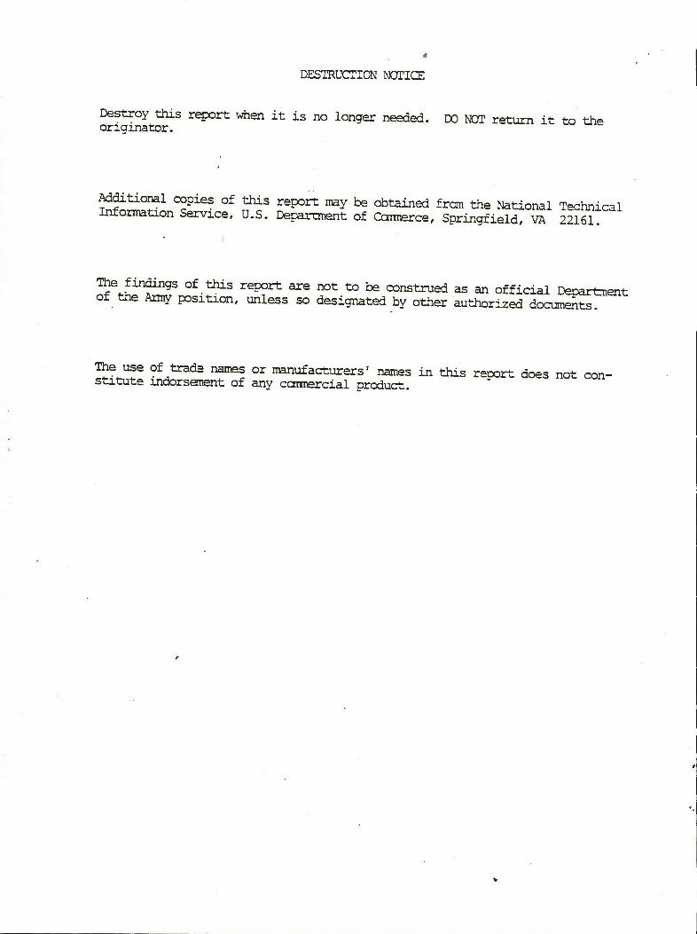
REPORT DOCUMENTATION PAGE Form Approved OMB No. 0704-0188
la. REPORT SECURITY CLASSIFICATION UNCLASSIFIED
lb. RESTRICTIVE MARKINGS
2a. SECURITY CLASSIFICATION AUTHORITY
2b. DECLASSIFiCATION/DOWNGRADING SCHEDULE
3. DISTRIBUTION/AVAILABILITY OF REPORT
APPROVED FOR PUBLIC RELEASE: DISTRIBUTION UNLIMITED.
4. PERFORMING ORGANIZATION REPORT NUMBER(S)
BRL-MR-3772
5. MONITORING ORGANIZATION REPORT NUMBER(S)
6a. NAME OF PERFORMING ORGANIZATION
Ballistic Research Laboratory
6b. OFFICE SYMBOL (If applicable)
SLCBR-TB-EE
7a. NAME OF MONITORING ORGANIZATION
6c ADDRESS {Crty, State, and ZIP Code)
Aberdeen Proving Ground, MD 21005-5066
7b. ADDRESS (Oty, State, and ZIP Code)
8a. NAME OF FUNDING/SPONSORING ORGANIZATION
Ballistic Research Laboratory
8b. OFFICE SYMBOL (If applicable)
9. PROCUREMENT INSTRUMENT IDENTIFICATION NUMBER
8c. ADDRESS (City, State, and ZIP Code)
Aberdeen Proving Ground, MD 21005-5066
10. SOURCE OF FUNDING NUMBERS
PROGRAM ELEMENT NO.
PROJECT NO.
TASK NO.
WORK UNIT ACCESSION NO.
11. TITLE (Include Security Classification)
EXPENDABLE DEARMER EVALUATION
12. PERSONAL AUTHOR(S) LAWRENCE J. VANDE KIEFI AND ALFRED L. BINES
13a. TYPE OF REPORT 13b. TIME COVERED FROM 88-10-01T0 89-03-01
14. DATE OF REPORT {Year, Month. Day) 15. PAGE COUNT
16. SUPPLEMENTARY NOTATION
17. COSATI CODES
FIELD
—w 1T
GROUP
"05"
SUB-GROUP
18. SUBJECT TERMS (Continue on reverse if necessary and identify by block number) Dearmer, Expendable Dearmer, MK 2 Dearmer Evaluation
19. ABSTRACT {Continue on reverse if necessary and identify by block number) The Ordnance, Missile, Munitions Center and School (OMMC&S) at Huntsville, AL, asked the Ballistic Research Laboratory (BRL) to study the problem of developing an expendable dearmer. Included in this study was the evaluation of a device that had been developed by a contractor, the AMETEK Company, in cooperation with the OMMC&S. This device purported to be an expendable dearmer, having all the required characteristics. This report details the experiments that were run to compare the performance of this device with that of the US Army MK 2 Mod O Dearmer. The performance of the AMETEK device was inferior to that of the MK 2 Dearmer, but the AMETEK Device is operationally more flexible in that it can use bulleted rounds as well as blank rounds. Only blank rounds were used in this evaluation.
20. DISTRIBUTION/AVAILABILITY OF ABSTRACT
Q UNCLASSIFIED/UNLIMITED D SAME AS RPT. □ DTIC USERS
21. ABSTRACT SECURITY CLASSIFICATION
UNCLASSIFIED 22a. NAME OF RESPONSIBLE INDIVIDUAL
Lawrence J. Vande Kieft 22b. TELEPHONE (Include Area Code)
(301) 278-6212 22c. OFFICE SYMBOL
SLCBR-TB-EE
DD Form 1473, JUN 86 Previous editions are obsolete. SECURITY CLASSIFICATION OF THIS PAGE
UNCLASSIFIED
CONTENTS
Page
LIST OF FIGURES v
ACKNOWLEDGEMENTS vii
1 INTRODUCTION 1
2 EXPERIMENTAL PROCEDURE 1
3 RESULTS 11
4 CONCLUSIONS 14
DISTRIBUTION 15
in
FIGURES
Page
1. AMETEK expendable dearmer 2
la. Photograph of exploded view of AMETEK expendable dearmer 3
2. Experimental setup for evaluating dearmers 4
3a. MK 2 Mod O dearmer in position for firing 5
3b. Close-up photo of MK 2 Mod O dearmer 5
4. Front face and slug from the MK 2 Mod O dearmer after impact, following
ricochet 6
5. Cineradiography system for rapid sequence x-ray imaging 7
6. Schematic diagram of the firing circuit 9
7. Sequences of x-ray images of AMETEK device number 1 test. These are
representative sequences, typical of most of the tests that were run 10
8. Dearmer slugs showing deformation resulting from impact 11
ACKNOWLEDGEMENTS
The authors are grateful to the following people for their help in the accomplishment of this
task: Mr. Steven Herman, OMMC&S, for technical discussions and suggestions; Mr. James
Petrousky, Naval Explosive Ordnance Disposal Technology Center, Indian Head, MD, for helpful
suggestions; Mr. Ned McCubbin, USATECHDET, NOS Indian Head, MD, for the loan of a MK 2
Mod O Dearmer, MSGT Sampson, Picatinny Arsenal, for providing the .50-Cal Impulse Cartridges
for use in the MK 2 and AMETEK Deaimers; Messrs. George Melani and Steven Stegall for
assistance in running the experiments; Mr. James Lawrence, an AMETEK consultant, for his
assistance in coordinating procurement of the various materials required for these tests and for his
participation in and validation of the tests; and especially to MSGT Ronald Deermer, Human
Engineering Laboratory, APG, MD, for raising the problem in the first place and providing much
helpful insight into its solution.
vu

1. INTRODUCTION
MSGT Ronald Deenner, currently attached to the US Army Human Engineering Laboratory
(HEL) at the Aberdeen Proving Ground, approached personnel at the Ballistic Research Laboratory
(BRL) with the problem of developing an expendable dearmer. Some efforts had been made in this
direction, but nothing had been accepted by the military. The BRL proposed several potential
solutions to this problem and was funded to pursue one of them, a shaped charge device. Included
in this study was the evaluation of a device that had been developed by a contractor, the AMETEK
Company, in cooperation with the Ordnance, Missile, Munitions Center and School at Huntsville,
AL. This device purported to be an expendable dearmer, having all the required characteristics. It
will be referred to in this report as the AMETEK device.
The AMETEK device is illustrated in Figures 1 and la. It is essentially a right circular
cylinder made from mild steel, bored to accept a cylindrical slug in the front and a .50-caliber
cartridge in the rear, having a shoulder separating the two chambers. A plastic insert is used to
match the shape of the cartridge to the hole bored to accept it; it fills the void space between the
cartridge and the chamber. A steel cap is screwed onto the back end of this device to hold the
cartridge in place.
There exist several different methods of de-arming explosive devices, one of which involves
the use of shaped charges to punch holes through the items, either causing them to initiate or
damaging them to the point where they would no longer pose a threat The devices discussed in
this report operate differently; they rely upon momentum transfer to the fuze of the ordnance being
de-aimed in such a way that the fuze is torn off or rendered inoperable without causing initiation.
For this reason, larger slugs traveling at high speeds are used. The speeds must be high enough to
disable the fuzes, but not high enough to cause initiation.
2. EXPERIMENTAL PROCEDURE
The basis for evaluation of the AMETEK devices was chosen to be a comparison between the
muzzle velocities of their slugs and dent depths, produced in aluminum armor witness blocks, with
velocities and dent depths produced by the MK 2 dearmer fired under identical conditions.
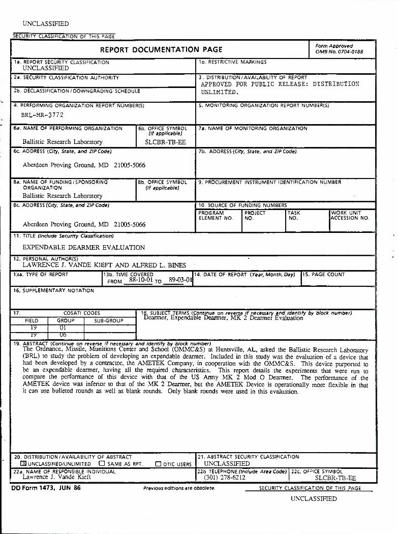
A schematic diagram of the experimental setup for evaluating the AMETEK devices is shown
in Figure 2; the associated photos are shown in Figures 3a and 3b.
Q- < u Q Z
LU
z
<
••••
0 a
<
z <
o u o in
/ \
E
r3 U
XI
Z ■o B O Q U
r- ■-1
>
u
c X
x: Q U SD 2 c x: a.
3
RHA Steel 6"x6"x1"
Mass: 4,540g
7039 Aluminum 8"x8"x2"
Mass: 5,700g
10" for AMETEK
12H for MK 2
Note: Not Drawn to Scale
Mild Steel Backing Plate: 6" dia. x 4" thick
1/2" hole for electric primer leads
L
Dearmer Device
Recess: 2.5" dia. 1.0" depth
Figure 2. Experimental setup for evaluating dearmers.

Figure 3a. MK 2 Mod O deamer in position for firing.
Figure 3b. Close-up photo of MK 2 Mod 0 dearmer.
Shots were fired vertically, to provide a more rigid recoil backstop and to provide a higher
degree of symmetry than would have existed in a horizontal configuration. One complication that
resulted from this was the damage that was caused by the steel slug ricocheting from the aluminum
witness plate onto the MK 2 dearmer and damaging its front face. It required repair twice during
this series of tests. Figure 4 is a photo of the front face o: the MK 2 and the top of the slag that
impacted it; the impact marks are clearly invisible.
A massive steel hlock was machined to accept the bac< of the dearmers and was rigidly
supported from beneath. In this way, recoil was minimized and was the same for all shots. The
dearmers were mounted in this backing block with their symmetry axis vertical and were aimed at
the middle of a witness plate configuration. This target configuration consisted of two plates, an
aluminum witness plate for dent depth recording and a steel plate to provide additional inertial
mass. Dimensions are shown in the figure.
Because of the different dimensions of the AMETEK devices and Jie MK 2 dearmers,
different stand-off distances were required between the rest position of the slug and the bottom of
the witness plate. This created no problem because velocity measurements were made before
impact to the witness plate, and -.here would be essentially no velocity change in the last increment
Figure 4. Front face and slug from, the MK 2 Mod O Dearmer after impact, following ricochet.
of travel. Also, dent depths from the AMETEK devices were meaningless because they used
unhardened steel slugs that mushroomed greatly upon impact. The impact, thus, produced very
shallow, wide dents not suitable for comparison with dents made by the MK 2 dearmer slugs.
Thus, most of the useful data came from the Cineradiography photos.
Figures 3a and 3b show some of the details of the mounting. Vertical alignment was achieved
by clamping the dearmers to a vertical piece of angle iron welded to the base plate. A standard
hose clamp, shown in the photos, was used for this purpose. The plywood shown is the protective
cover for the image intensifier screen. (The markings on the plywood have no meaning in this
experiment.)
Projectile speeds were measured by a Cineradiography system. A schematic diagram of this
system is shown in Figure 5.
This system consists of four x-ray tubes grouped together and directed across the target region,
through a protective sheet of plywood, onto an image intensifier screen. X-rays striking this screen
produce photons in the visible region of the spectrum, which are then focused onto four micro-
channel amplifiers, one for each x-ray tube. These amplifiers consist of two phosphor screens
separated by a bundle of capillary tubes internally coated with a phosphor. Photons from the image
intensifier screen strike the initial phosphor screen which emits electrons; the number depends upon
the intensity of the image at that point. These electrons are accelerated down the capillary tubes by
X
xoc X
"I
So
*5 XO •*
CO
>- «^ ■c UJ
vrCC 00
/\1
<S1
*
MO*? 3 06 J- OZ O bk-O O
4. o *—• I
■>■ u->
cC UJ UJ
UJ O
CO «C
I
_ 0 — no 0
f= ^ [= r- 1
si-
CO
6
Si Li. .. -■ CO
B o
Zz CO
—-„-^[ * 5
U o
to c '5
> 2
g c o 3 a o
j5
,0
> x: D a CJ o
« u U c U
M

a potential difference established between the two phosphor end screens. During their travel they
strike the phosphor coating on the capillary walls, causing more electrons to be emitted. These
electrons strike the final phosphor end screen and create an amplified optical image. In operation,
this screen is pressed directly onto a Polaroid film, thus exposing it to the shadow image of
whatever is in the target region at the moment of exposure.
The time resolution of this system is limited only by the relaxation time of the image
intensifier screen, which is somewhat less than 10 |J,sec. In these experiments, a fine conductive
wire was bound over the slug of the dearmer and attached to the firing circuit to act as a trigger.
Figure 6.
When this trigger wire broke, it initiated the timing sequence for taking the x-rays. In all of
the AMETEK dearmer shots, the following sequence was used: The firing button was pushed; the
trigger wire broke; 10 |isec later the first x-ray was taken, and the next three x-rays followed at
500-|isec intervals. In summary, x-rays were taken at the intervals of 10, 500, 1,000, and 1,500
|xsec after the trigger wire broke. This sequence yielded a nicely spaced set of images, almost
filling the available image space. The first image always showed the slug just after it began to
move; the second showed the slug almost out of the barrel or having just emerged; the third, the
slug travelling toward the witness plate; and the fourth, moments before impact Figure 7 shows a
typical sequence of these images.
The x-ray sequence was almost identical for the MK 2 dearaier shots. The only difference
was that the last x-ray was taken with a l,400-|4.sec delay instead of the 1,500-M5ec delay used for
the AMETEK shots. This was necessary because the slugs from the MK 2 dearmer had a slightly
higher speed, and they would have impacted the witness plate at the l,500-|isec delay time, making
it impossible to calculate the impact speed. In fact, one shot was spoiled because of this.
The left-hand sequence shows the static photos, one for each camera, from which comparisons
are made with the dynamic photos shown on the right. Use of this procedure avoids problems with
parallax and is necessary since the cameras are not coaxially emplaced.
The x-rays were read by using a Leitz Optical Comparator. Notice in Figure 7 the horizontal
and vertical reference lines in the background of each photo. The vertical lines are 100 mm apart,
and the horizontal lines are separated by 127 mm. In this set of experiments, only the horizontal
reference lines were used since these orthogonally intersect the direction of projectile flight. Using
these, the operator can directly read the position of the projectile for each x-ray, in other words, for
8
Power Designs
Model 6050A DC Source
In-house built
trigger circuit
1000A1 ow
Break-wire at Dearmer Device v^y
X-ray Time delays
(Four Channels)
—Copper Break-wire
-—Tape
Note: When slug moves, wire breaks which starts time delays on x-ray system. Tape is needed to insulate break- wire from slug as it ejects.
Figure 6. Schematic diagram of the firing circuit.
AMETEK Shot 1
+10 usec
+500 usec
+1,000 (isec
+1,500 \isec
STATIC IMAGES DYNAMIC IMAGES
Figure 7. Sequences of x-ray images of AMETEK device number 1 test. These are representative sequences, typical of most of the tests that were run.
10
TABLE 1. Projectile Data.
Slug mass, g Slug length, in before after
Slug diameter, in before after
AMETEK device no.
1 2 3 4 5
301.3 301.5 300.9 301.4 301.0
2.998 2.900 2.999 3.000 3.001
2.759 2.700 2.707 2.718 2.728
1.000 1.000 0.999 1.000 0.999
1.215 1.270 1.237 1.243 1.225
MK 2 dearmers
1 2
299.2 299.8
2.992 2.979
1.000 1.000
1.003*
* After three shots
NOTE: The mass of the steel inertial backing plate was 4,540 g. The aluminum witness plates
were made from 7039 aluminum, having the approximate dimensions 8-in square by 2-in
thick.
The cartridges that were used in all of these tests were identified as follows:
U.S. Navy NAVSEA
Cartridge, 50-Cal. Blank
(Electrically initiated)
1377-00-896-3694-M174
Lot No. CRA79D002-002
Five shots were fired with the AMETEK devices in the configuration in which they were
received. They were apparently designed to be used with either blank or bulleted cartridges. Since
these tests were performed with blank cartridges, there was a void space where the bullet would
normally be found. Each AMETEK device was supplied with a plastic insert to fill the space
between the cartridge case and the inside of the dearmer cylinder. In approximately half of the
shots, these plastic liners bonded tightly to the inside of the dearmers. In the remaining shots, they
could be removed and the dearmer immediately reused. In all cases after firing, the dearmers were
able to accept a new slug, so if a new cartridge could be inserted, they could be reused.
12

each time. Since four position-lime coordinates are known, three independent speeds can be
calculated. The speed of the slug at which it exits the dearmer is likely the most operationally
important speed because the slug length is the usual stand-off distance for this device; however, the
speed of impact is a better measure of performance.
3. RESULTS
As mentioned before, the criteria for performance were chosen to be projectile speed and depth
of dent in an aluminum armor witness block. The only usable dents were those made by the
hardened steel projectiles, those that came with the MK 2 dearmer, although they were also fired
from the AMETEK devices. The other slugs, those provided with the AMETEK devices,
mushroomed upon impact to the point that no useful dent resulted. Figure 8 shows a photo of the
five AMETEK slugs after they had been fired and of the two hardened steel slugs, one before and
the other after having been fired.
Table 1 lists the parameters pertinent to the projectiles that were fired. As can be seen, the
slug masses are very consistent within and between the two groups. This is also true of their
lengths and diameters. There is a greater variation in the mass of the wimess plates (Table 2), but
even that is a very small percentage and turns out to be irrelevant since dent depths formed no
basis for comparison of performance.
Figure 8. Dearmer slugs showing deformation resulting from impact.
11

Two additional AMETEK shots were fired, one with all conditions the same as before except
that a hardened slug was used, and the other with hardened slug and a cylindrical polyethylene plug
used to fill the void space normally occupied by the bullet.
Three data shots were fired with the MK 2 dearmer. Data from these shots and those
described above are in Table 2.
TABLE 2. Data from Dearmer Evaluation Tests.
Shot ID Final velocity, ft/sec
Dent depth/Vol, inAnl
Witness plate mass, g
Comments
AMETEK
1 2 3 4 5 9
603.17 590.3 629.85 604.07 601.09 693.59 0.266/3.4
5,738 5,733 5,633 5,637 5,717
Reused no. 5 w/no. 2 hard slug and Polyethylene plug
10 ■ 612.43 0.217/3.0 W/no. 2 hard slug and air space vice bullet or plug
MK 2
1 760.3 0.325/3.9 2 761.5 0.322/4.2 3 766.7 0.324/4.0
Note: No dent depth/volume data were obtained in shots 1-5 because mild steel slugs were used. See text for details.
13
4. CONCLUSIONS
The MK 2 dearmer yielded very uniform and consistent data for all three categories of
information, viz., projectile speed, dent depth and dent volume. The AMETEK devices yielded data
that were somewhat more scattered and that indicated lower perfonnance in terms of slug speed and
kinetic energy: Average projectile speed for the normal shots of the AMETEK devices was
605.69 ft/sec. This compares with 762.83 ft/sec, approximately 25% greater, for the MK 2. The
energies corresponding to these speeds, for the projectile masses used, are 5,129.45 J and
8,136.31 J, respectively.
These differences in performance were likely caused by the void volume ahead of the cartridge
in the AMETEK devices. When this was partially filled as in shot 9, the final slug speed, as
indicated in Table 2, was significantly greater than for those fired without the polyethylene spacer,
however, not as great as those achieved by the MK 2s with the same slug masses. This void space
does give the AMETEK device greater flexibility in that it can use bulleted rounds as well as blank
cartridges. Performance of the AMETEK dearmers was not evaluated with bulleted rounds in this
series of experiments.
In operation, these devices will not be as well supported in the rear as they were for these
tests. Consequendy, because of lower chamber pressure and reduced time for the propellant to
operate, there may be further degradation in performance, particularly for the less massive dearmers.
This will be true for any dearmer design that relies upon momentum transfer for its effectiveness,
and so is not a deficiency specific to the AMETEK design.
14
No of Copies
12
Organization
Administrator Defense Technical Info Center ATTN: DTIC-DDA Cameron Station Alexandria, VA 22304-6145
HQDA (SARD-TR) Washington, DC 20310-0001
Commander US Army Materiel Command ATTN: AMCDRA-ST 5001 Eisenhower Avenue Alexandria, VA 22333-0001
Commander US Army Laboratory Command ATTN: AMSLC-DL Adelphi, MD 20783-1145
Commander Armament RD&E Center US Army AMCCOM ATTN: SMCAR-MSI Picatinny Arsenal, NJ 07806-5000
Commander Armament RD&E Center US Army AMCCOM ATTN: SMCAR-TDC Picatinny Arsenal, NJ 07806-5000
Director Benet Weapons Laboratory Armament RD&E Center US Army AMCCOM ATTN: SMCAR-LCB-TL Watervliet, NY 12189-4050
Commander US Army Armament, Munitions
and Chemical Command ATTN: SMCAR-ESP-L Rock Island, IL 61299-5000
Commander US Army Aviation Systems Command ATTN: AMSAV-DACL 4300 Goodfellow Blvd. St. Louis, MO 63120-1798
Director US Army Aviation Research
and Technology Activity Ames Research Center Moffett Field, CA 94035-1099
DISTRIBUTION LIST
No of Copies Organization
Commander US Army Tank Automotive Command ATTN: AMSTA-DDL (Technical Library) Warren, MI 48397-5000
Director US Army TRADOC Analysis Command ATTN: ATAA-SL White Sands Missile Range, NM 88002-5502
Commandant US Army Infantry School ATTN: ATSH-CD-CSO-OR Fort Benning, GA 31905-5660
AFWL/SUL Kirtland AFB, NM 87117-5800
Air Force Armament Laboratory ATTN: AFATL/DLODL Eglin AFB, FL 32542-5000
Aberdeen Proving Ground Dir, USAMSAA
ATTN: AMXSY-D AMXSY-MP, H. Cohen
Cdr, USATECOM ATTN: AMSTE-TO-F
Cdr, CRDEC, AMCCOM ATTN: SMCCR-RSP-A
Cdr, USATEU ATTN:
SMCCR-MU SMCCR- MSI
SMCTE-OP, LT. Spencer Edgewood Area, BIdg. 5137
15
No of Copies Organization
HQDA DAMA-ART-M Washington, DC 20310
C.I.A. OIR/DB/Standard GE47 HQ Washington, D.C. 20505
Chairman DoD Explosives Safety Board ATTN: COL Powell Room 856-C Hoffman Bldg 1 2461 Eisenhower Avenue Alexandria, VA 22331
Commander Armament RD&E Center US Army AMCCOM ATTN: SMCAR-LCE, Dr. N. Slagg, Mike Joyce, Charles Capuccino Picatinny Arsenal, NJ 07806-5000
Commander US Army Armament Munitions and
Chemical Command ATTN: AMSMC-IMP-L Rock Island, 1L 61299-7300
Commander US AMCCOM ARDEC CCAC Benet Weapons Laboratory ATTN: SMCAR-CCB-TL Watervliet, NY 12189-4050
Commander CECOM R&D Technical Library ATTN: AMSEL-IM-L (Reports
Section) Bldg 2700 Fort Monmouth, NJ 07703-5000
Commander MICOM Research, Development and
Engineering Center ATTN: AMSMI-RD-CS-R (DOC) Redstone Arsenal, AL 35898
Commander US Army Development & Employment
Agency ATTN: MODE-ORO Fort Lewis, WA 98433-5000
Commandant USAFAS ATTN: ATSF-TSM-CN Fort Sill, OK 73503-5600
No of Copies
1
Organization
Commander US Army Research Office ATTN: Chemistry Division P.O. Box 12211 Research Triangle Park, NC 27709-2211
Office of Naval Research ATTN: Dr. A. Faulstick, Code 23 800 N. Quincy Street Arlington, VA 22217
Commander Naval Sea Systems Command ATTN: Dr. R. Bowen
SEA 061 Washington, DC 20362
Commander Naval Explosive Ordnance
Disposal Technology Center ATTN: Technical Library, Code 604 Indian Head, MD 20640
Commander Naval Research Lab ATTN: Code 6100 Washington, DC 20375
Commander Naval Surface Weapons Center ATTN: Code G13 Dahlgren, VA 22448-5000
Commander Naval Surface Weapons Center ATTN: Mr. L. Roslund, R10C Silver Spring, MD 20902-5000
Commander Naval Surface Weapons Center ATTN: Mr. M. Stosz, R10B Silver Spring, MD 20902-5000
Commander Naval Surface Weapons Center ATTN: Code X211, Lib Silver Spring, MD 20902-5000
Commander Naval Surface Weapons Center ATTN: Carl Gotzmer Silver Spring, MD 20902-5000
Commander Naval Weapons Center ATTN: Dr. L. Smith, Code 326 China Lake, CA 93555
16
No of Copies
1
Organization
Commander Naval Weapons Center ATTN: Dr. R. Atkins, Code 385 China Lake, CA 93555
Commander Naval Weapons Center ATTN: Dr. R. Reed, Jr., Code 388 China Lake, CA 93555
Commander Naval Weapons Station NEDED ATTN: Dr. Louis Rothstein, Code 50 Yorktown, VA 23691
Commander Fleet Marine Force, Atlantic ATTN: G-4 (NSAP) Norfolk, VA 23511
Commander Air Force Rocket Propulsion Laboratory ATTN: Mr. R. Geisler, Code AFRPL MKPA Edwards AFB, CA 93523
No of Copies
1
AFWL/SUL Kirtland AFB, NM 87117
Air Force Armament Laboratory ATTN: AFATL/Gary Parsons Eglin AFB, FL 32542-5000
Air Force Armament Laboratory ATTN: AFATL/Thomas Floyd Eglin AFB, FL 32542-5000
Commander Ballistic Missile Defense
Advanced Technology Center ATTN: Dr. David C. Sayles P.O. Box 1500 Huntsville, AL 35807
Director Lawrence Livermore National
Laboratories University of California ATTN: Dr. M. Finger P.O. Box 808 Livermore, CA 94550
Director Lawrence Livermore National
Laboratories University of California ATTN: Kenneth Scribner P.O. Box 808 Livermore, CA 94550
Organization
Director Lawrence Livermore National Laboratories University of California ATTN: Lee Frahm P.O. Box 808 Livermore, CA 94550
Director Los Alamos National Lab ATTN: Mr. J. Ramsey P.O. Box 1663 Los Alamos, NM 87545
Director Los Alamos National Lab ATTN: Mary Stinecipher P.O. Box 1663 Los Alamos, NM 87545
Irving B. Akst IDOS Corporation P.O. Box 285 Pampa, TX 79065
Director Sandia National Lab ATTN: Dr. Robert Carling Livermore, CA 94557-0096
Commandant USAOMMCS ATTN: ATSK-CME
Mr. Steven J. Herman, Mr. Eugene J. Squires, SGT Michael Caswell
Redstone Arsenal, AL 35897-6500
Commander Naval Surface Weapons Center ATTN: Dr. Kurt Mueller, Code R-10 Silver Spring, MD 20902-5000
Air Force Armament Laboratory ATTN: Dr. Michael Patrick Eglin AFB, FL 32542-5000
Director Los Alamos National Lab ATTN: Dr. Howard Cady P.O. Box 1663 Los Alamos, NM 87545
Commander Belvoir RD&E Center ATTN: STRBE-N, (Dr. David Hcbcrlcin) STRBE-NA (Dr. Herman Spitzer) STRBE-NAN (Ms. Pamela Jacobs)
(Mr. Rick Martinez) (Mr. Josh Williams) (Mr. Steve Bishop)
Fort Belvoir, VA 22060-5606
17
No of Copies Organization
Commander Naval Explosive Ordnance Disposal
Technology Center ATTN: Mr. James Petrousky, Code 601 Indian Head, MD 20640
Commander USATECHDET Naval Explosive Ordnance Disposal
Technology Center Indian Head, MD 20640-5096
James Lawrence AMETEK Company 5944 51st Ave. North St. Petersburg, FL 33709
18