Embed Size (px)
Citation preview

Membranes and MEA's for Dry, Hot Operating Conditions
Steven HamrockFuel Cell Components
June 10, 2008
FC13This presentation does not contain any proprietary, confidential, or otherwise restricted information

2
Overview
Timeline• Project start 4/1/07• Project end 3/31/11• 25% complete
BarriersA. DurabilityC. Performance
Budget• Total Project funding $11.4 million
- $8.9 million - DOE- $2.5 million - contractor cost share
(22%)• Funding in FY 2007• $0.8 Million (6 months)• Funding in FY 2008 • $1.2 Million (6 Months)
PartnersCase Western Reserve Univ.Professors T. Zawodzinski and D. SchiraldiColorado School of MinesProfessor A. HerringUniversity of Detroit MercyProfessor S. SchlickUniversity of TennesseeProfessor S. Paddison

3
Milestones• Year 1, Quarter 4: Complete the development of all pertinent testing methods and install and
modify new equipment as appropriate. Screening of new materials developed as part of Task 1 will be underway.
• Year 2, Quarter 4: Complete the identification of a first set of new, more conductive and durable materials.
• Year 3, Quarter 2: Go/no-go decision based on progress toward meeting DOE 2010 Membrane Technical Targets (this decision point coincides with the end of Budget Period 1). Membrane will have shown improvement over baseline material and measurable progress indicating a pathway to meeting DOE Membrane Technical Targets. The broad material classes showing the higher promise will be identified, based on performance in ex situ and single cell tests, and optimization of the final membrane structure and composition will begin.
• Year 4, Quarter 2: 3M will down select for the best performing catalyst/GDL/process based on performance in ex situ testing and single cell testing. Go/no-go decision for starting Subtask 4.1, Stack Fabrication and Testing.
• Year 4, Quarter 3: 3M will have assembled a short stack with the best stack components and prepared the stack for independent testing at DOE designated entity.
• To develop a new proton exchange membrane with:• higher proton conductivity• improved durabilityunder hotter and dryer conditions compared, to current membranes.
Project Objectives

4
Project Approach– New polymers, fluoropolymers, non-fluorinated polymers and composite/hybrid
systems with increased proton conductivity and improved chemical and mechanical stability
– Developing new membrane additives for both increased conductivity and improved stability/durability under these dry conditions
– Experimental and theoretical studies of factors controlling proton transport both within the membrane and mechanisms of polymer degradation and membrane durability in an MEA
– New membrane fabrication methods for better mechanical properties and lower gas crossover.
– Focus on materials which can be made using processes which are scalable to commercial volumes using cost effective methods
– Testing performance and durability. Tests will be performed in conductivity cells, single fuel cells and short stacks using realistic automotive testing conditions and protocols.

5
Project Approach• Task 1 Membrane Subcomponent
Development– Subtask Materials Development
(Polymer development, conductivity enhancing additive development and stabilizing additive development)
– Subtask Studies for Downselection (conductivity, membrane physical properties, failure and degradation mechanisms)
– Subtask Membrane Fabrication Process Development
• Task 2 MEA Fabrication and Testing (MEA fabrication, performance and durability test method development, initial performance testing, accelerated durability testing)
• Task 3 Final MEA Design and Integration (membrane fabrication, catalyst interface optimization and integration, final MEA optimization and fabrication)
• Task 4 Final Fuel Cell Testing (stack fabrication and testing, durability and performance testing)
• Task 5 Project Management, Deliverables and Reporting (building and testing short stack, reporting)

6
• Conductivity vs. temperature for EW ionomers in 640 – 980 EW range.
• The lowest EW ionomer tested so far, 640 EW, shows a conductivity of about 30 mS/cm at 120˚ C, 80˚ C DP, ambient pressure, very dry conditions, and meets DOE milestone for RT conductivity (ca. 80 mS/cm at 80%RH, 25C).
AC 4-point probe measurement.
Conductivity w/ Low EW
Conductivity versus Relative Humidity @ 25°C
0.01
0.10
1.00
60 70 80 90 100Relative Humidity (%RH)
Con
duct
ivity
(S/c
m) 640 EW
825 EW
0.01
0.10
1.00
80 100 120Temp (°C)
S/cm
3M PFSA 640 EW3M PFSA 730 EW 3M PFSA 830 EW 3M PFSA 900 EW 3M PFSA 980 EW
100 50 25
%RH
OCF2CF2CF2CF2
SO3H
(CF2CF)n(CF2CF2)m
3M Polymer

7
Polymer Modification – one approach
Polymer Research• A few example prepared w/ low
MW starting polymer.• Fluorocarbon/aromatic imides are
very chemically stable and highly acetic.
• Aromatic groups will be substituted with additional functionality for stable cross-linking and/or adding additional acid groups including HPA’s.
CF2
CF2
CF2
CF
O
F2C
CF2
F2C
CF2
S
F
OO
CF2
CF2
CF2
CF
O
F2C
CF2
F2C
CF2
S
N
OO
H HCF2
CF2
CF2
CF
O
F2C
CF2
F2C
CF2
S NOH
S
O
RO
O
NH3
1) RSO2X, R3N
2) H+
CF2
O2S NSO2
H
Polymer
CF2
O2S NSO2
H
Polymer

8
CF2
CF2
CF2
CF
O
F2C
CF2
F2C
CF2
S
O
OO
H
• Changing the nature of the acid group
Sulfonic acid• Lowest EW limited by monomer MW

9
SF3CO
O
CF2
CF2
CF2
CF
O
F2C
CF2
F2C
CF2
S
N
OO
H
• Changing the nature of the acid group
Perfluoro imides • Similar material prepared by
DesMarteau via polymerization of imide monomers with TFE
• Stronger acids than sulfonic acids• This example has been prepared, not
tested yet.

10
SO
O
CF2
CF2
CF2
CF
O
F2C
CF2
F2C
CF2
S
N
OO
H
• Changing the nature of the acid group
Aromatic imides • Useful synthetic handle• Similar pKa to sulfonic acids• Excellent thermal, hydrolytic and oxidative
stability. Further stability testing underway.
Conductivity versus Relative Humidity @ 25C
0.001
0.010
0.100
1.000
40 50 60 70 80 90 100Relative Humidity (%RH)
Con
duct
ivity
(S/c
m)
785 EW Bz imide
800 EW Sulfonic acid
• Starting with a low MW, 640 EW sulfony fluoride, a 785 EW imideionomer was prepared.
• This material has similar conductivity to an 800 EW PFSA control at 25ºC.

11
SO
O
HO3S
CF2
CF2
CF2
CF
O
F2C
CF2
F2C
CF2
S
N
OO
H
• Changing the nature of the acid group
Aromatic imides • Multiple acid groups• This example has been prepared• starting with a 640 EW polymer, this
ionomer should have an EW of 430.

12
SO
O
HO3S
HO3S
SO3H
CF2
CF2
CF2
CF
O
F2C
CF2
F2C
CF2
S
N
OO
H
• Changing the nature of the acid group
Aromatic imides • Multiple acid groups• EW could be < 280 !!• By increasing and/or changing
size and shape of pendant group, we hope to increase free volume of ionic regions, increasing water retention under hotter, drier conditions.
One possible example – has not been prepared

13
SO
O
CF2
CF2
CF2
CF
O
F2C
CF2
F2C
CF2
S
N
OO
H
H2O3P
• Changing the nature of the acid group
Aromatic imides • Phosphonic acid groups can allow:
• Attachment of HPA’s, • Attachment of zirconia particles
or zirconyl phosphate particles for increased conductivity, better mechanical properties, or latent cross-link.
Linking group(HPA’s Zircania)

14
SO
O
O2S
CF2
CF2
CF2
CF
O
F2C
CF2
F2C
CF2
S
N
OO
H
NHO2S
Polymer
• Changing the nature of the acid group
Aromatic imides • Crosslinking the ionic
region can allow lower EW’s to be more stable and prevent disruption of ionic structure at temperatures approaching Tα.
Cross-linking group

15
Cross-linking polymers – Objectives• Minimize swelling at high hydration levels.• Increase/eliminate α transition.• Conductivity and mechanical properties can be compromised above this transition • Improve mechanical properties.
• Compare properties of crosslinking hydrophobic matrix vs ionic domain.– Measure water uptake and conductivity.– Measure durability
• wet/dry cycling– H2O2
– Single cell tests
1.E+01
1.E+02
1.E+03
1.E+04
1.E+05
1.E+06
25 50 75 100 125 150 175 200Temp (C)
E' (
PSI)
0
0.1
0.2
0.3
0.4
0.5
0.6
0.7
0.8
0.9
1
Tan
Del
ta
Std. PFSA E'
3M Membrane E'
Std. PFSA Tan Delta
3M Membrane Tan Delta
Relevant previous work - DMA of Nafion™ and 3M Membrane (Both 1,000 EW) showing Tα
Changing or cross-linking the acid group may also have a big impact on Tα. A higher Tα may improve conductivity at higher temperatures.
Tα

16
0.0 300.0 600.0 900.0 1200.0 1500.0 1800.0 2100.0103
104
173.0
174.0
175.0
176.0
177.0
178.0
tim e [s]
¬*
()
[P]
Temp (
) [°C
]
Sample #1& 2, LM9-767 & 844, 175C, time scan, 3-20-08
x: 77.0 [s ] y : 1188.1 [P]
x : 18.0 [s ] y : 2176.0 [P]
x: 201.0 [s ] y : 1532.7 [P]
x: 607.0 [s ] y : 1986.6 [P]
x : 1207.0 [s] y : 2303.1 [P]
x: 1797.0 [s] y : 2523.0 [P]
x: 1507.0 [s ] y: 2419.7 [P]
Temp Sample #1 LM 9-767, 175C , time scan, 3-20-08 Sample #2 LM 9-844, 175C , time scan, 3-20-08
¬* Sample #1 LM 9-767, 175C , time scan, 3-20-08 Sample #2 LM 9-844, 175C , time scan, 3-20-08
Cure Rheology
Melt viscosity increase shows polymer is being cross-linked in SO2F form.
Swelling Experiments based on x-y dimensions SO3H form
Sample Water Glycol Methanol
Uncrosslinked Sample 30.6 63.3 solubleCrosslinked Sample 24.4 52.4 73.7
Swelling measurements show hydrolyzed samples are cross-linked.
Crosslinked ionomer using cure site monomerCrosslinking the hydrophobic matrix
• Standard fluoroelastomer cure systems for initial experiments.
• This is being used to understand the effects of cross-linking. More stable cross-links will be developed if this approach is successful.
Ionomer with Cure Site Monomer
CF2CF2 CF2CF
O
CF2
CF2
CF2
CF2
SO3H
CF2CF
O
CF2
CF2
Br
n ~0.03
x

17
Polymer Research New polymer structures with hydrocarbon polymers
• Hydrocarbon ionomers with fluorochemicalacids attached for improved conductivity.– Initial coupling reactions have been run.– Can be made into composites with PFSA’s?
• Prepare ‘hybrid’ polymers with perfluorinated and aromatic regions as hydrophobic and hydrophilic portions– Initial reactions have been run.– Durable linkages are key.

18
Example: Side-chain addition
• Cross-linking occurred in all trials and products formed gels and werepartially soluble
• In one case IEC=0.66 meq/g was obtained (Target was 0.86) and conductivity was around 80 mS/cm
* O
O2S
O*
* O
O2S
O*
CF2
F2CCF2
O
HO3S1. n-BuLi, THF, -70C2. Acylfluoride3. KOH4. H2SO4
F2CCF2
F2CS
OF
OO F• Model reactions carried out on small molecules to test
• Friedel-Crafts acylationunsuccessful
• Lithiation/ElectrophilicAddition (at right)successful

19
Studies of Transport in Polymer Electrolytes• This activity is just getting started; collaborative between Case Western and
Colorado School of Mines. • Use NMR relaxation and diffusion to probe local and long-range motion• Extend analysis as function of protogenic group, water content, equivalent
weight, polymer composition, blockiness etc.• Look for:
– tortuosity analysis– chain to chain hand-off? interaction?
• use polarization transfer, 2-D methods• sidechain mobility: C-13 relaxation
– changes in activation energies• threshold for increase as f(EW)?
• Eventually implement Electrophoretic NMR• First samples will be 3M PFSA of varying EW

20
SO2NH2
Br
SO2Cl
Br
+ Phosphonation
Br
SO2NH
SO2
Br
-HCl
(OEt)2OP
SO2NH
SO2
(OEt)2OP
(OH)2OP
SO2NH
SO2
(OH)2OP
Hydrolysis
Phosphonic Acids containing Bis sulfonyl imide
Zirconyl phosphate structure where imides control distance between platelets? We will attempt to attach this molecule to
HPA’s to generate chains or oligamers. These may immobilize the HPA’s
= SO2NHSO2
SO2N
H
SO2
This bis-phosphonate has been prepared.
21
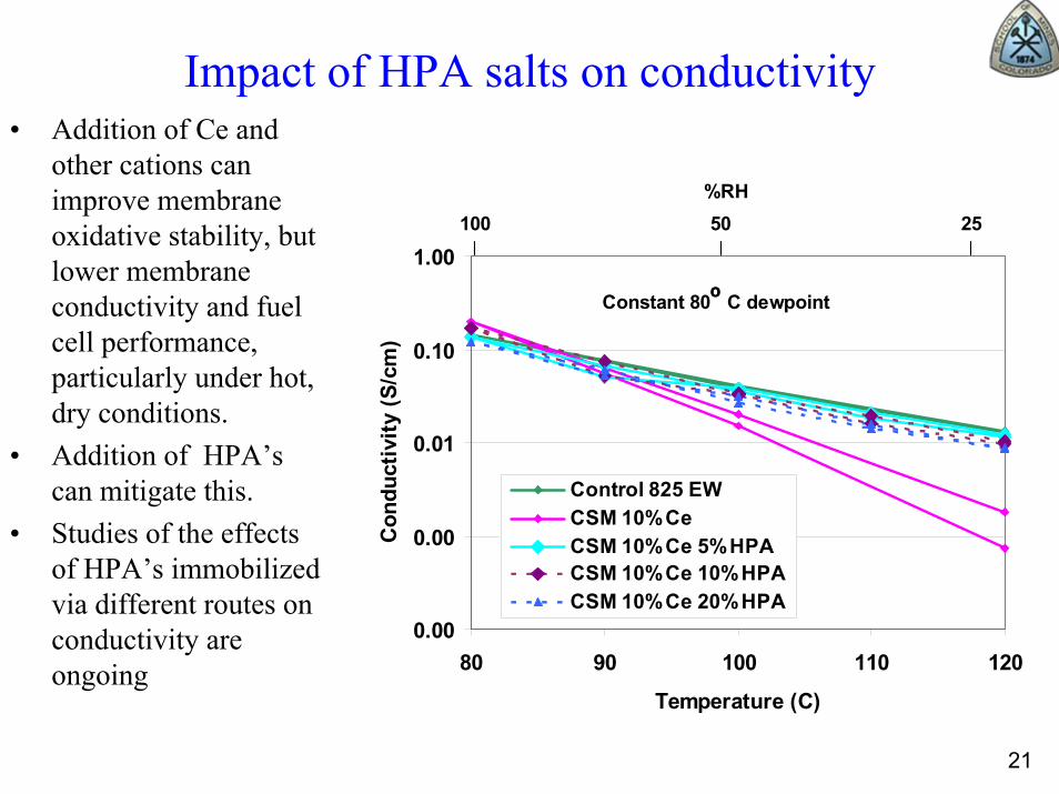
Impact of HPA salts on conductivity• Addition of Ce and
other cations can improve membrane oxidative stability, but lower membrane conductivity and fuel cell performance, particularly under hot, dry conditions.
• Addition of HPA’scan mitigate this.
• Studies of the effects of HPA’s immobilized via different routes on conductivity are ongoing
0.00
0.00
0.01
0.10
1.00
80 90 100 110 120
Temperature (C)
Con
duct
ivity
(S/c
m)
Control 825 EWCSM 10%CeCSM 10%Ce 5%HPACSM 10%Ce 10%HPACSM 10%Ce 20%HPA
Constant 80º C dewpoint
100 50 25%RH

3450 3460 3470 3480 3490 3500 3510 3520
3M (3.5%)/H2O2/DMPO/UV
DMPO/CCR 30%
DMPO/OH 70%
Simulation
Experimental: UV 6 min
Magnetic Field / G
Carbon-centered Adducts in Nafion™ and 3M in Aqueous Solutions
3450 3460 3470 3480 3490 3500 3510 3520
DMPO degradation 5%
DMPO/CCR 45%
DMPO/OH 50%
Simulation
Experimental: UV 14 min
Nafion (2.8%)/H2O2/DMPO/UV)
Magnetic Field / G
Carbon-centered radical (CCR) and •OH radical adducts were detected. The magnetic parameters for the CCR adducts in Nafion™ and 3M solutions are different, suggesting: (a) formation of different radicals, and (b) attack of •OH radicals on the side chain.
Oxygen Radicals Formed by UV-irradiation, DMPO as the Spin Trap
N
O
Me
MeH + R
N
O
Me
Me
Ηβ
R
DMPO Spin Trap DMPO/R Adduct

23
Effect of Ce(III) on the Intensity of theChain End Radical RCF2CF2•
3100 3200 3300 3400 3500 3600 3700
0
Integrated Intensity4538737442961123
70741013924
Fe(III) 0%, Ce(III) 10%
Nafion, 120 K, after UV 40 min
Fe(III) 10%, Ce(III) 90%
Fe(III) 10%, Ce(III) 70%Fe(III) 10%, Ce(III) 50%Fe(III) 10%, Ce(III) 35%
Fe(III) 10%, Ce(III) 20%Fe(III) 10%, Ce(III) 10%Fe(III) 10%, Ce(III) 5%Fe(III) 10%, Ce(III) 0%
Magnetic Field / G0 20 40 60 80 100
0.0
0.5
1.0
1.5
2.0
2.5
Nor
mal
ized
Inte
nsity
/ a.
u.
Ce(III) % (constant Fe(III) 10%)
The chain end radical is not generated when the membrane contains only Ce(III), and no Fe(III).For a constant 10 % neutralization by Fe(III), Ce(III) is an effective stabilizer of membrane fragmentation when the degree of neutralization by Ce(III) is ≥10%.
Nafion™ Membranes with Constant Fe(III) Concentration

24
Model Compounds –Approach and recent progress• Developed initial approach to testing aromatic sulfonic acid model compounds
– Initial evaluation of MC’s has begun.– Many aromatic sulfonic acids and other model compounds readily degrade in
Fenton’s reagent solution– Systematically ‘harvesting’ small molecule analogs from synthetic activity to
explore degradation pathways– Considering oxidation, hydrolysis and other degradation modes
• Recently received new LC/MS for rapid turnaround on degradation product analysis• Extensive analysis of perfluorosulfonic acid degradation products, 19F NMR carried out• Developing new methods to explore other possible degradation pathways
– Could sulfonate cleavage be more favorable in presence of Pt?• Collaboration beginning between Case Western and Detroit-Mercy
S
O
O
FF
OHHO
O
S
O
O
OH
SN
SCF2
CF3
Li
O
O
O
O
H

25
Fluoride bond
Energy of C-F bond dissociation (kcal/mol)
F1 103.60F2 114.92F3 108.78F4 105.14F5 102.77F6 105.43
Bond type Energy of bond dissociation (kcal/mol)
C6-S 61.15C5-C6 79.96C4-C5 75.77C3-C4 80.96O-C3 81.26C1-C2 76.83
Bond Dissociation Energies of 3M fragment
F1
F2
F3
F4
F5
F6
F1
F2
F3
F4
F5
F6
C1
C2
C3
C4
C5
C6
O
S
C1
C2
C3
C4
C5
C6
O
S
• Nafion™, 3M ionomer and the short side chain (Dow) ionomer have been investigated.
• All show, qualitatively, that the C-S bond is the weakest. Possible sight of side-chain attack?
• An investigation into the energetics and kinetics of reaction of the fragments with hydroxyl radicals has begun.

26
• Nafion™, 3M ionomer and the short side chain ionomer have been investigated.
• It appears that the longer side in the 3M membrane results in larger water domains with higher density than the SSC PFSA membrane.
• Need to account for backbone crystalinity.• Add other protogenic groups (size and
acidity?).
SSC 3MEW = 678
(λ = 16
λ = 11
Meso-scale modeling of MorphologyDissipative Particle Dynamics (DPD) simulations

27
Performance Testing• Developed Humidity Performance Test - Hold the dew point constant at
80°C and gradually raise cell temperature from 80 to 120°C (Record performance and impedance)
Durability Testing Protocol Development• 95ºC OCV Hold
• One station running this protocol and we have begun to run samples. • SHIVA 1 Automotive Protocol
• Protocol carried over from previous automotive development. • Four Cells commissioned. One sample set started.
• SHIVA 2 Automotive Protocol with 120ºC Excursion• Equipment upgrade complete• New protocol currently being tested
• Mechanical Membrane Humidity Cycle• Equipment upgrade complete• New protocol currently being tested
Test Method Development

28
Fuel Cell TestingDown selection of screening electrode• Time was spent evaluating different
electrodes for increased performance in the screening of MEAs. We do not want the electrode to limit evaluation of new PEMs.
• Cursor study of such electrode variables as:– I/C ratio– Ionomer EW– GDL type– Catalyst type
• We have down-selected V2 for our screening process.
Performance Gains• Over 300 samples have been screened
for performance.• Gains in performance seen with –
– Thinner PEMS– Lower ew– New Chemistries– New Additives
0
0.1
0.2
0.3
0.4
0.5
0.6
0.7
70 80 90 100 110 120 130
V1HFR V1V2HFR V2V3HFR V3V4HFR V4
Cell
Volta
ge (v
olts
)@
0.5
Am
ps/c
m2
Cell Temperature (oC)
H2/Air CS 2.0
Ambient Pressurex/8080oCCounter Flow
0.2
0.3
0.4
0.5
0.6
0.7
80 85 90 95 100 105
1000 ew 30 um1000 ew 5um644 ew 25um733 ew 30 um825 ew CSM additive 30um
Cel
l Vol
tage
(Vol
ts)
@ 0
.5 A
mps
/cm
2
Cell Temperature (oC)
H2/Air CS 2.0 70oC Dewpoint Inlets
Ambient Pressure Outlets Co-Flow

29
Oxidative Stability/Durability Gains
• We have screened over 200 samples over our contract so far.
• Variables showing an influence on FRR include:
– Additives– Different PEM constructs.– Electrode effects.
• Additive A in 825 EW 3M membrane also provides about 1,000 hours lifetime at 120º C.
• Relatively high humidity and pressure.
• Future testing will be done at lower pressure, drier conditions.
1
10
100
1000
10000
No
Add
itive
Con
trol
3M A
dditi
ve A
Mul
tilay
er N
o A
dd
CSM
HPA
Add
itive
B
CSM
HPA
Add
itive
C
Oxidative StabilityH
2O
2 90oC 30%RH Ambient Pressure OCV
Flou
ride
Rel
ease
Rat
e
(ug/
day/
cm2 )
0
0.1
0.2
0.3
0.4
0.5
0.6
0.7
0.8
0
1
2
3
4
5
6
0 200 400 600 800 1000 1200
Cel
l Vol
tage
(Vol
ts)
@ 0
.4 a
mps
/cm
2
FRR
(ug/day/cm2)
Time (hours)
H2/Air CS 2.5/2
120oC 80/95%RH inlet
Counter Flow 30psig 102cm2

30
Future Work• Continue preparation and evaluate conductivity and durability of low EW and new imide
containing polymers.• Prepare and test membranes crosslinked in both the hydrophilic and hydrophobic regions.• Produce low EW/MW ionomer segments for ‘Hybrid’ polymers.• Demonstrate synthesis of aromatic membrane or monomer unit with perfluorosulfonic acid side
chain and ‘Hybrid’ polymers: Key focus on creating stable ‘links’.• Probe key factors in transport using NMR relaxation and diffusion, SAXS, QCM measurements,
conductivity and other spectroscopy measurements. Develop better understanding of effect of low lambda on proton transport.
• Prepare and test zirconyl analogs of new polymers and small molecules.• Immobilize stabilizing metal ions/HPA through synthesis of novel HPA as stand alone insoluble
salts or grafting to ionomer backbone or inorganic nanoparticle.• Describe degradation pathways for current group of model compounds.• Quantify the intensity of the •OH radicals in the Fenton reaction based on Ce cations in aqueous
solutions. • Quantify the intensity of the carbon-centered radicals (CCRs) generated in the Fenton reaction in
aqueous solutions in the presence of model compounds.• Assess mechanism of Ce stabilization in dry 3M and Nafion™ membranes. • Complete hydrated morphology comparison of the three PFSA ionomers: Nafion™, SSC, and 3M
ionomer. EW comparison and degree of hydration (λ=3-20)• Undertake first principles modeling of crystallinity through a comparison of the three PFSA
ionomers and aromatic backbone ionomers with perfluorinated sulfonic acid side chains.• Complete chemical stability comparison of Nafion™, SSC, and 3M ionomer. (1) Bond
dissociation energies; (2) Kinetics and thermodynamics of reaction with hydroxyl and peroxylradicals.
• Begin longer term single cell durability testing.

31
Summary
* tested at 25ºC** not same EW membrane as conductivity test
2008 Status 2010 target 2015 target
Conductivity at 120º C S/cm 0.03 (25%RH) 0.1 0.1
Conductivity at 80º C S/cm
0.05 (50%RH) 0.29 (100%RH) 0.1 0.1
Conductivity at 30º C S/cm
0.08 (80% RH)* 0.07 0.07
Conductivity at -20º C S/cm Not tested 0.01 0.01
O2 cross-over mA/cm2 Not tested 2 2
H2 cross-over mA/cm2 <2 2 2
Durability w/ cycling** hours
> 5000 (80ºC) <1000 (120ºC)
5000 (80ºC) 2000 (120ºC)
5000 (80ºC) 5000 (120ºC)
• This project involves using experiment and theory to develop an understanding of factors controlling proton transport and the chemical/physical durability of the membranes.
• New materials are being synthesized based on this understanding, and evaluation of these materials will further our understanding.
• This “feedback loop” will ultimately allow for materials “designed” to meet performance and durability targets.
• Several approaches or pathways to new membranes are being investigated. We expect the final membrane will combine some or all of these. We will not “down select” just one approach.