Embed Size (px)
Citation preview
MEMBRANE SEPARATION OF OLEFINS FROM FCC NAPHTHA AND GASES FOR PRODUCTION OF REFORMULATED GASOLINE
G.P. Sakellaropoulos, H. Plaggesis, G-H Koops, M. Makhlouf
Foundation of Research and Technology - Chemical Process Engineering Research Institute
Hellenic Aspropyrgos Refinery University of Twente Fluent Europe Ltd.
Contract JOE3-CT97-0052
PUBLISHABLE FINAL REPORT
1-12-1997 to 30-10-2000
Research funded in part by
THE EUROPEAN COMMISSION in the framework of the
Non Nuclear Energy Programme JOULE III
Membrane Separation of Olefins from FCC Naphtha and Gases for Production of Reformulated Gasoline
3. Abstract
The new EU directives will require reduction of olefins in gasoline from 30% to 12% to reduce the environmental impact of transportation fuels. The only available technologies today for olefin reduction in FCC-derived gasoline require new investments, with high energy consumption and operating costs in a refinery. Furthermore their environmental impact is significant since they require large quantities of pollutant materials, such as catalysts. This project aimed to achieve the desirable olefin separation with reduced energy requirements, no need for hydrogen and catalysts, and no reduction in gasoline quality (RON). The objectives of this project were to develop: (i) a membrane system for more energy efficient and more profitable olefin separation, (ii) a system for naphtha production with predetermined amounts of olefins, without RON (Research Octane Number) losses, (iii) olefins recovery for further exploitation, (iv) software for membrane process simulation and scale-up, and (v) the technoeconomic evaluation of the process.
The methodology to accomplish these goals included first the selection of the most suitable polymer material for olefin paraffin separation. Seven membrane materials have been selected and flat sheet membranes were prepared and characterised. Taking into account the permeability, selectivity, price and availability, a polyimide (Matrimid 5218) was selected as the best material to use for developing hollow fibre membranes. Several configurations of hollow fibre modules were prepared and tested for polymer plasticization, and finally a module with polymer housing and heat treated fibres of sufficient chemical strength, was adopted for pilot experiments. For the pilot membrane gas separation and pervaporation testing two pilot units were designed and constructed, based on the vacuum time-lag method.
The Hellenic Aspropyrgos Refinery performed six commercial tests for the production of samples at various flow rates, with two catalysts, covering the most extreme cases for FCC naphtha and gas compositions. These samples were used in the gas separation and pervaporation pilot tests. The membrane pilot experimental conditions were varied in the range of ∆p = 1-2 bar, stage cut θ = 0.1-0.4, and temperatures 20-70oC.
Initial tests with untreated fibres showed a decline of membrane separation performance with time, possibly due to plasticisation or condensation phenomena in the polymer. With the thermally heated fibres, steady state permeation was achieved and working temperatures up to 70oC were possible. This operating temperature ensured high permeation rates and absence of condensation effects inside the membrane. Results show a significant increase of olefins concentration in the permeate stream especially at low stage cuts. Selection of the optimal stage cut depends on the objective goal of the application. For the production of olefin rich streams a small stage cut is needed, while for the recovery of LPG isoparaffins higher stage cuts are preferable. Increase of the feed pressure results in improved olefin purity and recovery, while at the same time, the paraffin purity and recovery in the residue also increase.
For liquid phase olefin/paraffin separations, a pervaporation module was prepared and tested using four light naphtha samples, two from the FCC pilot unit and two from the HAR refinery. From group type analysis, the membrane seems to be selective in olefins and unsaturated naphthenes. However, the results showed that the membrane is much more selective in hydrocarbons with small number of carbon atoms, and this could be an indication that steady state conditions may have not been reached.
Experimental and pilot tests results were used to develop and validate a 1D and a 3D model and simulation code for hollow fibre membrane separations. A 1D simulation code for a
single hollow fibre separation was completed by CPERI, describing the gas separation and the pervaporation of olefins and paraffins in the gas and liquid state, respectively. The 1D model results compare well with experimental data on gas separation of olefins and paraffins in the pilot membrane unit. Also, a 3D code was developed by FLUENT, describing the flow, pressure and concentration profiles inside the hollow fibre module. The obtained results compare also well with the experimental and the respective results of 1D code.
Using data from experimental and model results, a technoeconomic evaluation of three alternative processes for olefin separation was undertaken: (i) Hydrogenation, (ii) Undercut Distillation, and (iii) Membrane Separation. At present membrane technology has the highest Pay Out Time (POT) of all other technologies. However, with minor improvement of operational conditions, the POT can decrease considerably (about 100%). Therefore the proposed membrane technology has high potential to become economically competitive to the conventional techniques. Furthermore, its attractiveness for olefin paraffin separation from FCC naphtha is strengthened by its environmental friendliness since it does not require, pollutant materials, such as catalysts.
4. Partnership The groups, which participated in the project, are: Foundation of Research and Technology – Chemical Process Engineering Research Institute P.O. Box 1520 54006, Thessaloniki Greece Contact: Prof. G.P. Sakellaropoulos Hellenic Aspropyrgos Refinery 16 km Athens-Corinth National Road 193 00, Aspropyrgos Greece Contact: H. Plaggesis University of Twente Faculty of Chemical Technology P.O. Box 217 7500 AE Enschede, The Netherlands Contact: Dr G-H Koops Fluent Europe Ltd Holmwood House Cortworth Road Sheffield, S11 9LP United Kingdom Contact: Dr M. Makhlouf 5. Objectives
The new EU directives will require reduction of olefins in gasoline from 30% to 12% to
reduce the environmental impact of transportation fuels. The only available technologies today for olefin reduction in FCC-derived gasoline are distillation and hydro-treating. These processes, however, require new investments, with high-energy consumption and operating costs in a refinery. Furthermore their environmental impact is significant since they require large quantities of catalysts. The project aimed to achieve the required olefin separation with reduced energy requirements, no need for hydrogen and catalysts, and no reduction in gasoline quality (RON).
The development of a membrane process for olefins separation from FCC naphtha and lighter gases has significant environmental benefits. The final reformulated gasoline, which could be obtained, will have a strong influence in decreasing the total gasoline vehicle emissions. Moreover, the technological solution for olefin separation via membrane technology would have an indirect environmental impact, through the decrease in the required energy, which in turn is related to lower emission from the various utility plants. Concerning safety,
membrane separations would avoid the high pressures employed in hydrogen hydro-treating technologies, and thus would offer safer operation in the oil-industries. The production of high RON gasoline components by the membrane technology should possibly create a lower dependence of the gasoline pool on alkylate gasoline.
The olefins, which are recovered by the examined methodology constitute an additional, indirect benefit. The separated and recovered olefins can be used as raw materials in other processes for the production of petrochemicals, for the production of oxygenates and for the production of alkylate gasoline.
The innovative technology for olefin separation is of great importance for the large number of European refineries, leading to more economic and energy efficient production of environmentally friendly gasoline. To meet these technological needs, this project aimed to develop an innovative system, based on membrane technologies, for the separation of olefins from FCC naphtha and gases. The objectives of the project were:
• Development of a membrane system for a more energy efficient and more profitable olefin separation.
• Development of a system, which could lead to the production of naphtha with predetermined amounts of olefins, without RON losses, aiming at reduced cost reformulated gasoline.
• Recovery of olefins for further exploitation. • Development of software for membrane simulation and scale-up. • Technoeconomic evaluation of the proposed process. Most of these objectives were met in this project, although a number of scientific
questions have arisen in its course.
6. Technical description
The first step of the work was the selection, synthesis and modification of a number of polymer membrane materials. Bench scale experiments were performed in order to determine their olefin/paraffin permeability and selectivity properties, and to study the effect of operating variables (pressure, temperature, concentration). Various glassy and rubbery polymers were investigated, while blending and modification of selected polymers was also examined, to attain lower cost and higher temperature and chemical resistance. The permeation experiments included both gas and liquid hydrocarbons depending on the boiling point.
The selected polymer material was then used to prepare hollow fibre membranes for pilot plant testing for gas separation and pervaporation. Various techniques of hollow fibre spinning were investigated including tube-in-orifice and triple-layer spinning. Other crucial factors i.e. solvent, non-solvent, fast and slow coagulation, as well as the membrane characteristics (integrally skinned membrane, composite membrane, top-layer thickness) were also taken into account. The prepared hollow fibre asymmetric membranes were characterised by SEM, FT-IR, DSC, XRD, DSR. At least two types of hollow fibre modules were prepared, one for each separation technique, i.e. for gas separation and pervaporation.
Two pilot units one for gas separation and one for pervaporation were designed and constructed. These units consist of the respective hollow fibre modules and all necessary ancillary equipment for T, P, flow control and sampling of all streams.
Olefin/paraffin separations are examined in the pilot plant units, both for gas separation and pervaporation. Gas experiments included the separation of LPG supplied from refinery commercial tests and from samples from a FCC pilot unit. The pervaporation pilot unit was fed with liquid hydrocarbons, which were supplied from both refinery commercial tests and the
FCC pilot plant. The experimental protocols included several samples and various operating conditions, i.e. pressure, temperature and stage cut.
In order to analyse the permeation phenomena, a mathematical model was developed and used for a one-dimensional and a three-dimensional hollow fibre module. The latter, which is applicable in large membrane systems, examines the mass, and momentum field gradients inside the hollow fibre module. Both model were validated with experimental results.
For the production of necessary samples used in the membrane pilot unit, the refinery performed a number of commercial tests in its plant. These samples were produced under specific conditions, which covered the most extreme cases for FCC naphtha and gas compositions, and included various feed-stocks and catalysts at various operating conditions (flow rate, catalyst/oil ratio, temperature).
Using input from experimental and modelling results, a technoeconomic study was carried out in order to assess the gain for the refinery if this method is applied for olefin separation, for the production of reformulated gasoline and of high olefinic streams. The study also compared membrane technology with the conventional technologies used currently for the production of reformulated gasoline (hydrotreating or distillation). 7. Results and conclusions
Polymer materials evaluation and preparation
From the extensive literature review it was identified that the most promising polymer
materials for both gas and liquid phase hydrocarbon separations are the polyimides. Seven commercial polymers, named: Matrimid 5218 (Ciba-Geigy), Pyralin PI 2566 (6FDA-ODA polyamic acid, by Du Pont de Nemours, Germany), P84 (Lenzing), Torlon (Amoco), PPO (General Electric), polyetherimide (Aldrich) and a BPDA-based polyimide in hollow fibre form (Ube) have been tested at CPERI and UT-CT labs. The selection of these polymers was based mainly on their chemical structure, which indicated that the above materials probably have interesting permeation, mechanical and chemical resistance properties.
Blending techniques of the above polyimides with compatible polymers have also been applied in order to improve the chemical and mechanical stability of the membranes. For this purpose, flat sheet membranes have been prepared, with polymer blends of Matrimid with polysulfone (CPERI), and Matrimid with Thermid (UT-CT), at proportions 20:80 and 85:15, respectively.
The selection of the most effective polymer in terms of olefin/paraffin separation is based on permeation experiments at various operating conditions for several gas hydrocarbons, which are components of the LPG in FCC products. Experimental results of propene/propane permeation through the BPDA-based hollow fibre membranes, showed that BPDA polyimide has low selectivity for C3
=/ C3 separations. The same pair of hydrocarbons has also been examined by UT-CT, and the results are shown in Table 1. Comparison of the selectivity values for the tested materials shows that Matrimid 5218 and Pyralin 2566 have the highest selectivity (αID). However, Pyralin is not a good option because it is a very expensive material ($ 1225 per kg for a 15 % wt solution) and it is applied in the form of a polyamic acid solution. This means that for the polyimide formation a special heat treatment is required, which is not feasible in preparing hollow fibre membranes by spinning. The Matrimid/Thermid blends exhibited lower selectivity than pure Matrimid, and therefore are excluded from further examination. PPO membranes showed high permeability (P) but their selectivity was lower than that of Matrimid. Additionally, PPO requires the use of ethanol instead of water as a
coagulant, which is very inconvenient for preparing hollow fibre membranes. Finally, Torlon has a very low permeability and does not seem to be a suitable candidate for future work.
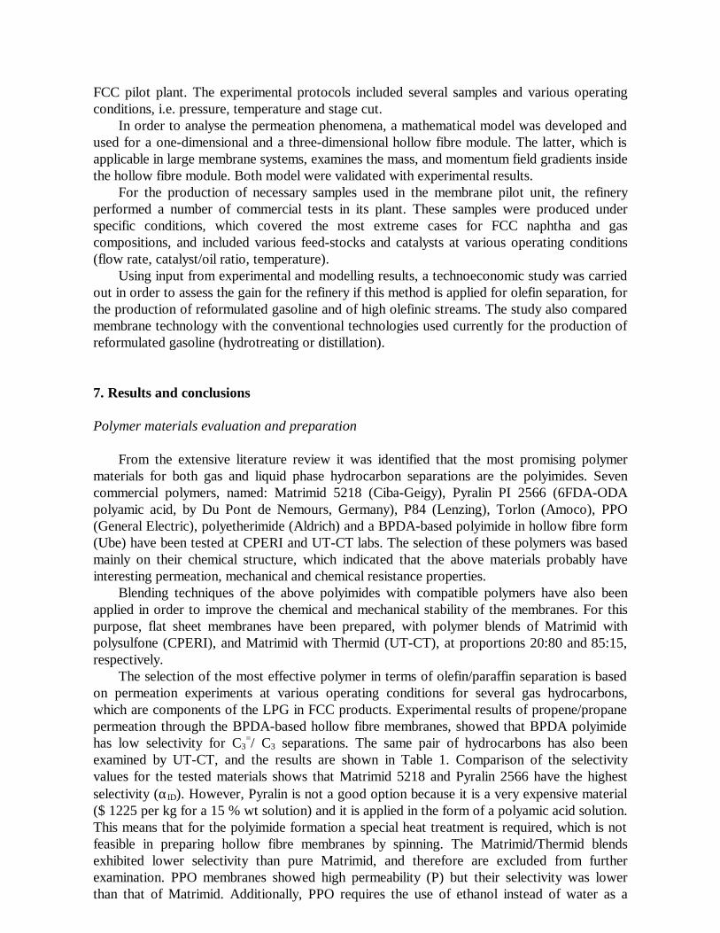
Extensive gas separation experiments were also carried with additional hydrocarbons, at several operating conditions. Most of LPG olefins and paraffins have been tested in order to evaluate the permeation properties of the most promising polymeric dense membranes, (Table 2). The selectivity values of Matrimid for C4 olefin/paraffin separation are quite high, especially for n-butane, which is the most permeable hydrocarbon. It should be noted that good agreement is attained on the permeability values of n-propane, measured in both laboratories. However, in the case of propene, tests carried out at CPERI showed significant evidence of Matrimid plasticization by this particular hydrocarbon.
Table 1: Permeabilities of propane/propene on various flat sheet homogeneous membranes
Membrane type Thickness (µm)
Feed pressure (bar)
Propane P(Barrers)
Propene P(Barrers)
αID
Matrimid 5218 30 3 0.012 0.109 9 Matrimid 5218 18 2 0.004 0.088 22 Matrimid/Thermid 31 3 0.008 0.028 4 Pyralin 2566 19 3 0.004 0.086 21 Torlon 23 3 <0.020 <0.020 - PPO 27 3 0.240 2.570 11 PPO 49 2 0.260 1.670 6 PPO 41 2 0.220 2.000 9
1Barrer = 10-10 cm3(STP) cm / (cm2 s cmHg) The results presented in Table 1 and 2, show that the most effective polymer material for
C3-C4 olefin/paraffin separation is Matrimid 5218, which exhibited the best permeability and selectivity behaviour. Further lab evaluation of gas hydrocarbon mixtures was not deemed necessary since the single hydrocarbon results provide all the necessary information for the final selection of this material among all examined, prospective polymers.
Table 2: Permeability coefficients of LPG hydrocarbons in Matrimid 5218 at 27-29°C Feed Pressure (Torr)
Permeability coefficient (Barrers)
Propane n-Butane 1-Butene i-Butane i-Butene
250 - 5.524 0.011 0.006 0.052 500 0.011 5.797 0.008 0.003 0.042 1000 0.009 5.639
5.257 0.006 0.002 0.037
0.032 1500 - 5.864 0.006 0.002 0.036
1Barrer = 10-10 cm3(STP) cm / (cm2 s cmHg) ; 1 Torr= 760 mm Hg
The activation energy (Ep) values for propane permeation in polyimides 6FDA-TeMPD,
6FDA-TrMPD, 6FDA-DDBT and 6FDA-ODA are 4, 9, 29 and 34 kJ/mol, respectively [Tanaka et al, 1996]. The obtained value of Ep for propane in Matrimid 5218 (16.8 kJ/mol) lies in the middle of the literature data for 6FDA-based polyimides, which are considered the best materials for the specific gas.
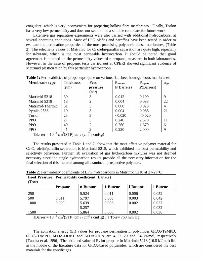
In order to further increase the permeation rate of Matrimid 5218 and to investigate the feasibility of hollow fibre membrane preparation, asymmetric flat membranes were prepared by an immersion-precipitation process. This technique includes an evaporation step prior to coagulation of the polymer film. The presence of a low boiling point component, such as acetone in the casting solution makes this evaporation step easier. Therefore, a casting solution, containing 25 % wt Matrimid, 37.5 % wt NMP and 37.5 % wt acetone, was prepared. Films were cast into a glass plate, evaporated in the open air for a certain time and coagulated by transferring the glass plate into de-ionised water.
Results on C3=/C3 separation through Matrimid asymmetric films are shown in Table 3
(UT-CT). Since the thickness of the skin layer of the asymmetric membranes is not known the permeability is expressed as the thickness normalised permeability P/l. The obtained propene/propane selectivities (about 20) are in good agreement with those obtained for the dense membranes (Table 1) but in this case the permeation rate is considerably higher since the membrane thickness is substantially lower.
Table 3: Propane and propene permeation rates of asymmetric Matrimid films at 30°C and 3bar
Evaporation time (min) (P/l)propane (Ba/µm) (P/l)propene (Ba/µm) αID 1.5 0.0019 0.039 20 5 0.0015 0.027 18
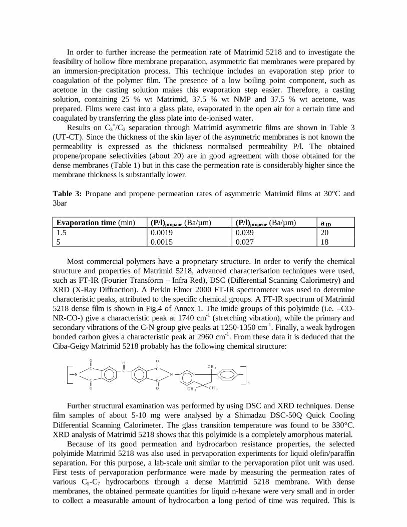
Most commercial polymers have a proprietary structure. In order to verify the chemical
structure and properties of Matrimid 5218, advanced characterisation techniques were used, such as FT-IR (Fourier Transform – Infra Red), DSC (Differential Scanning Calorimetry) and XRD (X-Ray Diffraction). A Perkin Elmer 2000 FT-IR spectrometer was used to determine characteristic peaks, attributed to the specific chemical groups. A FT-IR spectrum of Matrimid 5218 dense film is shown in Fig.4 of Annex 1. The imide groups of this polyimide (i.e. –CO-NR-CO-) give a characteristic peak at 1740 cm-1 (stretching vibration), while the primary and secondary vibrations of the C-N group give peaks at 1250-1350 cm-1. Finally, a weak hydrogen bonded carbon gives a characteristic peak at 2960 cm-1. From these data it is deduced that the Ciba-Geigy Matrimid 5218 probably has the following chemical structure:
O
C
C
O
N
O
C
C
O C H 3C H 3
C H 3
n
N
O
C
Further structural examination was performed by using DSC and XRD techniques. Dense film samples of about 5-10 mg were analysed by a Shimadzu DSC-50Q Quick Cooling Differential Scanning Calorimeter. The glass transition temperature was found to be 330°C. XRD analysis of Matrimid 5218 shows that this polyimide is a completely amorphous material.
Because of its good permeation and hydrocarbon resistance properties, the selected polyimide Matrimid 5218 was also used in pervaporation experiments for liquid olefin/paraffin separation. For this purpose, a lab-scale unit similar to the pervaporation pilot unit was used. First tests of pervaporation performance were made by measuring the permeation rates of various C5-C7 hydrocarbons through a dense Matrimid 5218 membrane. With dense membranes, the obtained permeate quantities for liquid n-hexane were very small and in order to collect a measurable amount of hydrocarbon a long period of time was required. This is
probably due to the relatively high thickness of the dense membrane examined (about 50 µm), and the size of the permeate manifold which was originally designed for higher permeation rates. Since this behaviour is also expected for the rest of the liquid hydrocarbons, modification of the experimental set-up was necessary. Modifications include the use of low thickness asymmetric membranes and the redesign of the permeate manifold in order to accomodate for bench scale tests. Nevertheless, conclusions drawn on the permeation behaviour of polyimide Matrimid 5218 for gas olefin/paraffin separation are also valid in pervaporation, since both processes are based on similar mass transfer phenomena.
To-date no studies have been reported on the separation of liquid olefins and paraffins by means of the pervaporation process. This technology has been applied, however, to dehydration of organic solvents, removal of organic compounds from aqueous solutions, and separation of anhydrous organic mixtures, resulting in significant energy savings compared to classical distillation. The membranes, which are used in pervaporation, are made of polymers in homogeneous or asymmetric form. Several imide polymers are extremely resistant to solvent dissolution, and hence, these polymers are of particular interest for preparing membranes used in organic – organic separations, where membrane stability is of primary importance due to the relatively harsh conditions. The olefins and paraffins of C5 – C7 have similar boiling points and molecular shapes, and it is difficult to separate them, since they may have similar diffusion coefficients. Therefore, their solubility differences should be a key factor to achieve selective separation. The selective enhancement of olefin solubility may be achieved by choosing a polymer material with higher affinity to olefins than to paraffins.
Olefin/paraffin separation could be considered similar to aromatic/paraffin separation, due to the existence of π-electron clouds in the >C=C< (double) bond, in both the olefins and the aromatic structure. In the open literature there are only few, very recent, papers on separation of aromatics and paraffins on polymer membranes, via pervaporation; these were used as an initial starting point for the selection of potential polymers in the present study. The best permeation behaviour, in terms of separation factor and permeation rate, was shown by the DSDA-DDBT polyimide for the separations of benzene/n-hexane, toluene/n-octane, toluene/i-octane, and n-octane/i-octane. The efficiency of this polyimide was attributed to the existence of sulfonyl groups in the molecular structure of both the DSDA dianhydride and the DDBT diamine. The sulfonyl groups as well as the carbonyl or amino groups contribute to the enhancement of the affinity to the aromatic components. Thus, it is assumed that the interaction between the sulfonyl, or amino, or carbonyl groups of the polyimides and an aromatic molecule is stronger than that for a paraffin with the same number of carbon atoms, resulting to higher solubility for the aromatics. The same rule could be valid in the case of olefin/paraffin separation, and in the beginning of the present study this specific class of imide polymers was considered as the most appropriate.
Based on the above considerations, CPERI selected two commercial polymers: Matrimid 5218 (Ciba-Geigy Ltd.), a polyimide with carbonyl groups in the dianhydride structure, and polysulfone, PSF (Amoco), a glassy polymer with sulfonyl groups. The mechanical strength of these materials is very good at elevated temperatures, at least to 180°C. In addition, their chemical resistance in a C5-C7 olefins and paraffins environment is also very good. A third series of potential materials, PEBAX (a range of Polyether Block Amides family), which are rubbery polymers, was proposed by UT-CT according to their experience in separation of toluene in mixtures with heptane, decane, dodecane, tetradecane or hexadecane. Four different PEBAX samples (2533-SA01, 3533-SA01, 4033-SA01 and 6333-SA00 grades) were kindly offered by UT-CT. However, PEBAX grades 2533 and 3533 do not show good chemical resistance to paraffins, while the chemical compatibility of 4033 grade with benzene is not very good, and may be worse with olefins. Thus, CPERI scientists selected PEBAX grade 6333 for
evaluation. Matrimid 5218 and PSF homogenous dense membranes were prepared by casting a 4% wt
solution into petri dishes. Methylene chloride and chloroform were used as solvents for Matrimid and PSF solutions, respectively. After solution casting the solvent was evaporated for 1 day at room temperature and then, the flat sheet films were removed from the plates by immersion in water. Finally, the membranes were dried in an oven for 3 days by slowly increasing the temperature from 25 to 250°C for Matrimid, or to 180°C for PSF.
In the case of PEBAX 6333, a 4wt % solution in formic acid was prepared. This technique was used, in analogy to grade 2533 and 3533 casting, based on UT-CT experience with the latter. The polymer could not be dissolved at room temperature even after one week agitation; a clear solution was prepared only at a temperature of 50°C. The hot casting solution resulted in shrinkage at room temperature and the prepared membranes cracked. At a second attempt, the solution was spread cold, but membranes with only small homogenous sections were prepared, since polymer lumps formed when the solution was cooled. These results show that PEBAX 6333 can not provide a stable, defect-free membrane with the currently available method of casting. Further exploration of this material did not seem necessary, since PEBAX is a rubbery polymer, which would be difficult to cast into asymmetric hollow fibres.
Blending techniques of the above polyimides with compatible polymers have also been applied in order to improve the chemical and mechanical stability of the membranes. For this purpose, flat sheet membranes have been prepared, with polymer blends of Matrimid with PSF at a proportion of 20:80.
Membranes prepared from polyimide, polysulfone and their blend were tested for liquid olefins and paraffins pervaporation. Initial tests with n-hexane on dense Matrimid membranes did not permit collection of sufficient liquid permeate to evaluate pervaporation rates. Therefore, the pervaporation unit was modified to measure the pressure change with time on the permeate side, similar to the gas separation procedure. The feed was liquid hydrocarbons, circulated by a peristaltic pump, as described in our report on the pervaporation pilot unit. This approach was successful for the evaluation of permeate rates at room temperature. Higher feed temperatures caused some vapour formation in the recycle stream and required careful pressure regulation of the feed side of the pervaporation cell. Feed flow rates of about 300 ml/min were found effective in providing regular flow on the feed side, while higher circulation rates caused localised mechanical strain and possibly chemical "erosion" of the membrane.
The evaluation of the potential polymers was based on the permeation behaviour of n-hexane, 1-hexene and n-heptane, through Matrimid 5218 and PSF dense membranes. Several n-hexane experiments were carried out to determine the necessary experimental time, for steady state permeation, both in Matrimid and PSF. These tests show very good reproducibility, which also indicates the lack of a plasticization phenomenon. After extensive study of n-hexane, in terms of permeability and total productivity, the suitability of each subsequently tested film was then examined using n-hexane, as a reference material, before any experiments with the other hydrocarbons. These experiments showed that PSF is more permeable than Matrimid, without loss in selectivity. In addition, n-heptane is the most permeable hydrocarbon, in both PSF and Matrimid 5218. The permeability of n-hexane is slightly higher than 1-hexene at steady state conditions, but the total productivity of n-hexane is lower than that of 1-hexene in the tested polymers. This happens because the pressure increase in the transient state is more rapid in the case of 1-hexene, but in the steady state the permeation rate of n-hexane is higher. The similarity of results with pure PI and PSF membranes indicated that there would be no advantage to explore further PSF-PI blends for this application.
Based on the obtained results it appears that both polyimide and polysulfone have
sufficient selectivities for the separation of liquid hydrocarbons with different number of carbon atoms. For a paraffin and an olefin with the same number of carbon atoms selectivity can be acceptable under certain operating conditions. Polysulfone is a chemically resistant glassy polymer, with good mechanical and permeation properties for liquid paraffins and olefins. Furthermore, it is an available and cheap commercial polymer. Therefore, it is considered as a potentially suitable material for further investigation in pilot scale tests with real C5-C7 mixtures.
Membrane formation and characterisation The polyimide Matrimid 5218 was selected as the most suitable membrane material for
olefin/paraffin separation. This material was then used for the preparation of hollow fibre membranes and the construction of membrane modules for pilot plant testing. By varying spinning parameters such as dope composition, bore liquid composition and flow rates, Matrimid hollow fibres were prepared with different top layer thicknesses.
Hollow fibre membranes were produced by pumping the spinning dope (polymer solution) and bore liquid through a double orifice spinneret. Water (21°C) was used as the coagulant. Before entering the water bath, the fibre went through an air gap of 20 cm. The function of the air gap is to include an evaporation step prior to coagulation. The evaporation step is necessary to increase the polymer concentration on the outside of the fibre, which is important in obtaining defect-free top layers.
The airgap was formed by a cylindrical, thermostated stainless steel tube which hereafter will be referred to as the chimney. On the inside of the chimney a porous metal structure was present through which a N2 flow of 2 ml/min was introduced. This construction of the air gap allowed to create a reproducible and controllable environment in the air gap.
Spinneret, spinning dope reservoir, chimney and N2 flow into the chimney were all thermostated. Fibres were collected, rinsed in water overnight and dried by a liquid displacement method. Hereto the fibres were placed in ethanol for at least four hours and then placed in n-hexane for at least four hours. Finally, the fibres were dried overnight in a vacuum oven at 30 °C
Spinning dopes were prepared from Matrimid (MM), N-methylpyrrolidone (NMP) and acetone (Ac). Acetone is a non-solvent for Matrimid. It was added to the spinning dope since it is a low boiling point component, which should facilitate the evaporation step. For the bore, liquid mixtures of NMP and water in different ratios were used.
The dimensions and structures of the prepared fibres were determined by Scanning Electron Microscopy. Furthermore, the fibres were characterised by gas permeation measurements. Hereto, small modules containing five fibres each were prepared. The permeation rate was determined the same way as was described in section 1.1. In case of the hollow fibres, a vacuum was present on the bore side of the fibre while the feed was applied to the outside of the fibres.
Previous gas permeation experiments with flat sheet membranes showed that the time to reach a constant permeability value is much larger when gases such as propane and propene are used instead of, for example, O2 and N2. To reduce the time necessary for determining the gas permeation behaviour and checking whether produced fibres were defect-free and selective, it was decided to characterise the fibres with O2 and N2. Using homogeneous Matrimid films the intrinsic permeabilities for O2 and N2 were determined: PO2 = 1.602 Barrer PN2 = 0.236 Barrer. This gives an ideal selectivity of: αO2 / N2 = 6.8. Using the intrinsic permeabilities of Matrimid, the thickness of the dense top layers of these fibres can be calculated from the measured permeation rates (P/l). The top layer thickness of the fibres is calculated to be in the range of 1.4 to 1.9 µm.
Two fibres were used to determine the permeation properties for propane and propene. The results are shown in Table 4. A propene/propane selectivity of 27-28 could be achieved, which is even higher than the selectivity previously determined with flat sheet homogeneous dense Matrimid films. This confirms that Matrimid has been a good material selection.
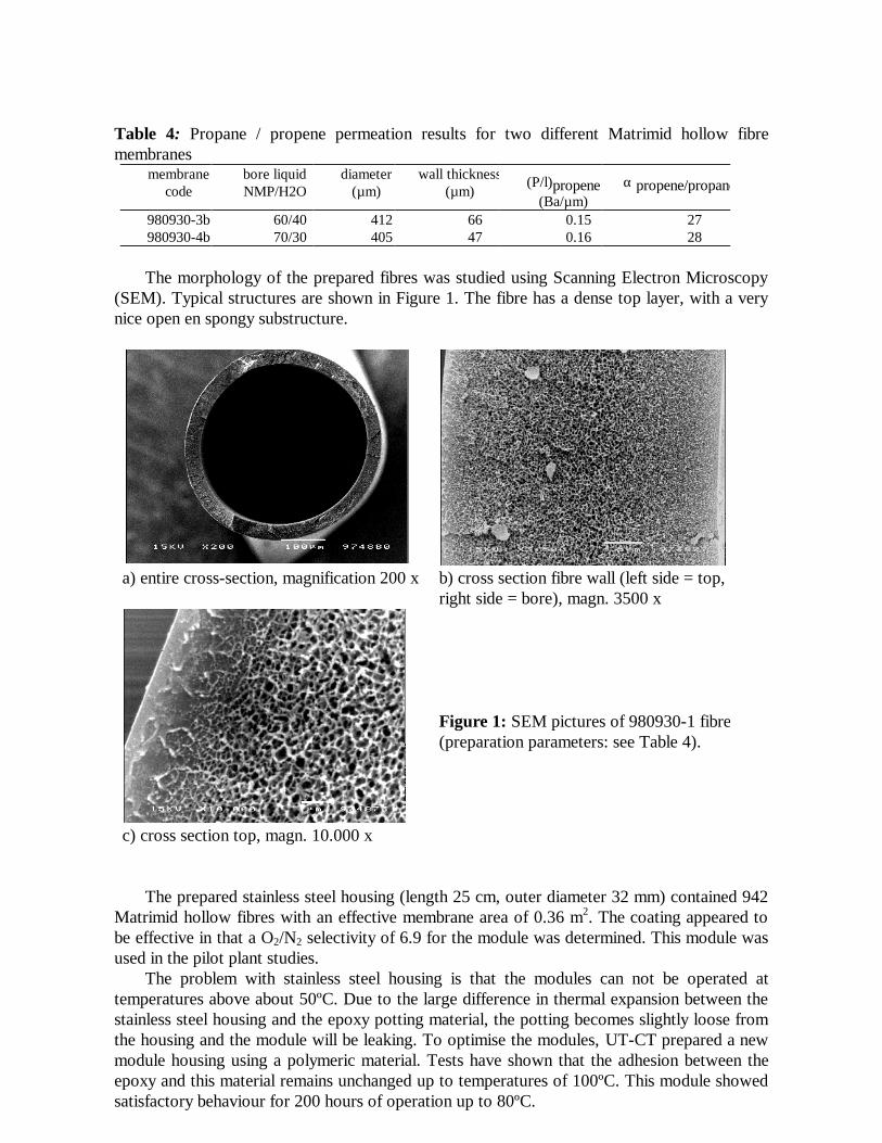
Table 4: Propane / propene permeation results for two different Matrimid hollow fibre membranes
membrane code
bore liquid NMP/H2O
diameter (µm)
wall thickness(µm)
(P/l)propene (Ba/µm)
α propene/propane
980930-3b 60/40 412 66 0.15 27 980930-4b 70/30 405 47 0.16 28 The morphology of the prepared fibres was studied using Scanning Electron Microscopy
(SEM). Typical structures are shown in Figure 1. The fibre has a dense top layer, with a very nice open en spongy substructure.
a) entire cross-section, magnification 200 x b) cross section fibre wall (left side = top,
right side = bore), magn. 3500 x
Figure 1: SEM pictures of 980930-1 fibre (preparation parameters: see Table 4).
c) cross section top, magn. 10.000 x The prepared stainless steel housing (length 25 cm, outer diameter 32 mm) contained 942
Matrimid hollow fibres with an effective membrane area of 0.36 m2. The coating appeared to be effective in that a O2/N2 selectivity of 6.9 for the module was determined. This module was used in the pilot plant studies.
The problem with stainless steel housing is that the modules can not be operated at temperatures above about 50ºC. Due to the large difference in thermal expansion between the stainless steel housing and the epoxy potting material, the potting becomes slightly loose from the housing and the module will be leaking. To optimise the modules, UT-CT prepared a new module housing using a polymeric material. Tests have shown that the adhesion between the epoxy and this material remains unchanged up to temperatures of 100ºC. This module showed satisfactory behaviour for 200 hours of operation up to 80ºC.
All the optimisation techniques (fibres heat treatment and use of polymeric housing) have been applied to the preparation of two new modules, one for gas separation and one for pervaporation. These improved modules, containing heat-treated fibres inside polymeric housing, were also used in pilot plant testing.
Membrane pilot unit design and construction Gas separation vacuum unit
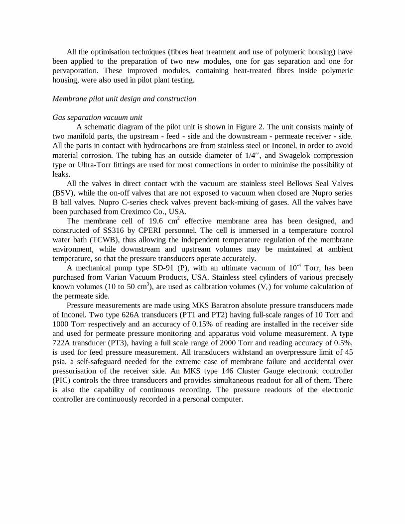
A schematic diagram of the pilot unit is shown in Figure 2. The unit consists mainly of two manifold parts, the upstream - feed - side and the downstream - permeate receiver - side. All the parts in contact with hydrocarbons are from stainless steel or Inconel, in order to avoid material corrosion. The tubing has an outside diameter of 1/4′′, and Swagelok compression type or Ultra-Torr fittings are used for most connections in order to minimise the possibility of leaks.
All the valves in direct contact with the vacuum are stainless steel Bellows Seal Valves (BSV), while the on-off valves that are not exposed to vacuum when closed are Nupro series B ball valves. Nupro C-series check valves prevent back-mixing of gases. All the valves have been purchased from Creximco Co., USA.
The membrane cell of 19.6 cm2 effective membrane area has been designed, and constructed of SS316 by CPERI personnel. The cell is immersed in a temperature control water bath (TCWB), thus allowing the independent temperature regulation of the membrane environment, while downstream and upstream volumes may be maintained at ambient temperature, so that the pressure transducers operate accurately.
A mechanical pump type SD-91 (P), with an ultimate vacuum of 10-4 Torr, has been purchased from Varian Vacuum Products, USA. Stainless steel cylinders of various precisely known volumes (10 to 50 cm3), are used as calibration volumes (Vc) for volume calculation of the permeate side.
Pressure measurements are made using MKS Baratron absolute pressure transducers made of Inconel. Two type 626A transducers (PT1 and PT2) having full-scale ranges of 10 Torr and 1000 Torr respectively and an accuracy of 0.15% of reading are installed in the receiver side and used for permeate pressure monitoring and apparatus void volume measurement. A type 722A transducer (PT3), having a full scale range of 2000 Torr and reading accuracy of 0.5%, is used for feed pressure measurement. All transducers withstand an overpressure limit of 45 psia, a self-safeguard needed for the extreme case of membrane failure and accidental over pressurisation of the receiver side. An MKS type 146 Cluster Gauge electronic controller (PIC) controls the three transducers and provides simultaneous readout for all of them. There is also the capability of continuous recording. The pressure readouts of the electronic controller are continuously recorded in a personal computer.
Pure paraffins (propane, n-butane and isobutane), pure olefins (propene, 1-butene, and isobutylene) and a gas mixture containing C3-C7 hydrocarbons in nitrogen, are used in the gas permeation tests. The pure hydrocarbons are in a liquefied gas state and have an N20 to N35 purity, while the gas mixture is a special order. Pure nitrogen (N50) is used as an inert gas for volume calibrations. All gases are supplied by Air Liquide Co. and Messer Griesheim Co.
Figure 2 : Flow diagram of the vacuum unit for gas hydrocarbons permeability tests. Pervaporation pilot unit
CPERI designed and constructed the pilot unit for pervaporation tests, based on the vacuum method. This unit was modified in order to enhance the sensitivity and to evaluate in bench-scale laboratory experiments, the performance of different polymer membranes for the C5-C7 olefins/paraffins separation. After the production of the pervaporation membrane module, the pervaporation unit was rearranged to its initial configuration, capable to be connected with a pilot scale module, so that light naphtha samples could be tested.
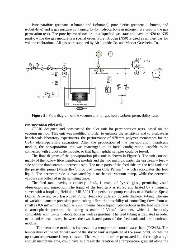
The flow diagram of the pervaporation pilot unit is shown in Figure 3. The unit consists mainly of the hollow fibre membrane module and the two manifold parts, the upstream – feed – side and the downstream – permeate side. The main parts of the feed side are the feed tank and the peristaltic pump (Masterflex®, procured from Cole Parmer®), which recirculates the feed liquid. The permeate side is evacuated by a mechanical vacuum pump, while the permeate vapours are collected in the sampling traps.
The feed tank, having a capacity of 4L, is made of Pyrex® glass, permitting visual observation and inspection. The liquid of the feed tank is stirred and heated by a magnetic stirrer with a hotplate, Heidolph MR 3001.The peristaltic pump consists of a Variable–Speed Digital Drive and two Easy-Load Pump Heads for different outside diameter tubing. The use of variable diameter precision pump tubing offers the possibility of controlling flows from as small as 0.6 ml/min to as high as 2900 ml/min. Since liquid hydrocarbons in the feed side flow at atmospheric pressure, the tubing is made of Viton® elastomer, which is chemically compatible with C5-C7 hydrocarbons as well as gasoline. The feed tubing is insulated in order to minimise heat losses, between the two heated parts of the feed tank and the membrane module.
The membrane module is immersed in a temperature control water bath (TCWB). The temperature of the water bath and of the stirred tank is regulated at the same point, so that the upstream temperature is kept constant. The evaporation of the permeated liquid through a high enough membrane area, could have as a result the creation of a temperature gradient along the
B V 1
B V 2
B S V 1
N 2
C Hx y
B S V 7B SV 8
B S V 6
B S V 3
B S V 5
B SV 4
C ELLT C W B
T IC
G C
D
P
V ent
V ent
B S V 2
C V
CV
T
P C V PI
P C V P I
S
S
S
S
S P T 1 P T 2
P T 3
PIC PR
S SS
V c
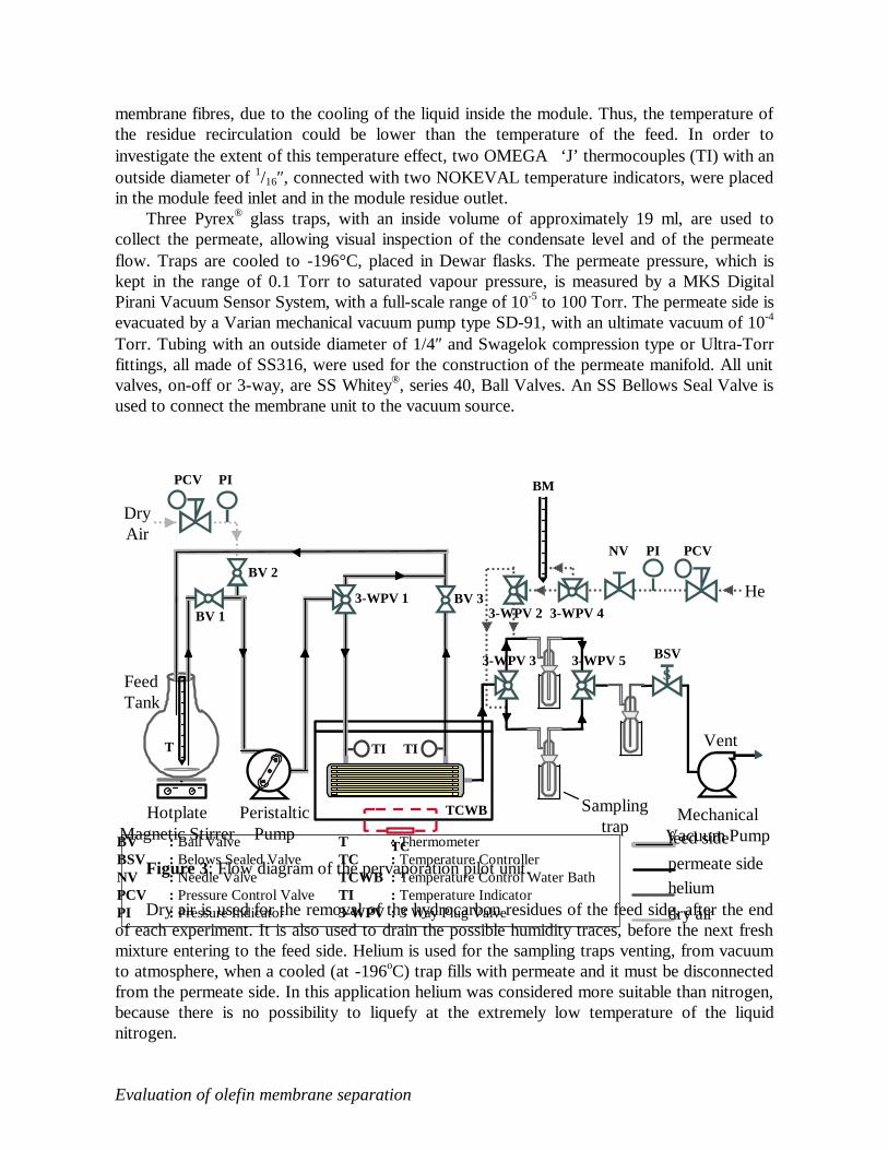
membrane fibres, due to the cooling of the liquid inside the module. Thus, the temperature of the residue recirculation could be lower than the temperature of the feed. In order to investigate the extent of this temperature effect, two OMEGA ‘J’ thermocouples (TI) with an outside diameter of 1/16″, connected with two NOKEVAL temperature indicators, were placed in the module feed inlet and in the module residue outlet.
Three Pyrex® glass traps, with an inside volume of approximately 19 ml, are used to collect the permeate, allowing visual inspection of the condensate level and of the permeate flow. Traps are cooled to -196°C, placed in Dewar flasks. The permeate pressure, which is kept in the range of 0.1 Torr to saturated vapour pressure, is measured by a MKS Digital Pirani Vacuum Sensor System, with a full-scale range of 10-5 to 100 Torr. The permeate side is evacuated by a Varian mechanical vacuum pump type SD-91, with an ultimate vacuum of 10-4 Torr. Tubing with an outside diameter of 1/4″ and Swagelok compression type or Ultra-Torr fittings, all made of SS316, were used for the construction of the permeate manifold. All unit valves, on-off or 3-way, are SS Whitey®, series 40, Ball Valves. An SS Bellows Seal Valve is used to connect the membrane unit to the vacuum source.
Figure 3: Flow diagram of the pervaporation pilot unit.
Dry air is used for the removal of the hydrocarbon residues of the feed side, after the end of each experiment. It is also used to drain the possible humidity traces, before the next fresh mixture entering to the feed side. Helium is used for the sampling traps venting, from vacuum to atmosphere, when a cooled (at -196oC) trap fills with permeate and it must be disconnected from the permeate side. In this application helium was considered more suitable than nitrogen, because there is no possibility to liquefy at the extremely low temperature of the liquid nitrogen. Evaluation of olefin membrane separation
HotplateMagnetic Stirrer
FeedTank
T
PeristalticPump
TC
TCWB MechanicalVacuum Pump
Vent
PCVPI
BM
NV
He
SBSV
PCV PI
DryAir
BV 1
BV 2
BV 33-WPV 13-WPV 2 3-WPV 4
3-WPV 3
TI TI
3-WPV 5
Samplingtrap
BV : Ball Valve BSV : Belows Sealed Valve NV : Needle Valve PCV : Pressure Control Valve PI : Pressure Indicator
T : Thermometer TC : Temperature Controller TCWB : Temperature Control Water Bath TI : Temperature Indicator 3-WPV : 3 Way Plug Valve
feed side permeate side helium dry air
Olefin/paraffin separation in the gas separation hollow fibre unit
In the gas phase olefin/paraffin separations, the prepared gas separation modules were tested using gaseous mixtures from C3 to C7 hydrocarbons, and four commercial LPG samples. The evaluation of the membrane performance was accomplished by measuring the following variables: separation factor ((yi/yj)/(xi/xj)), permeance (Pi/l), olefin purity and recovery in the permeate stream, and paraffin purity and recovery in the residue streams. The influence of the basic operational parameters such as transmembrane pressure, ∆p, temperature, T, and stage cut, θ, and the feed concentration was examined.
In the gas separation pilot scale tests, two types of membrane modules were used. The first module contained a bunch of thermally untreated hollow fibres inside a stainless steel housing. The second module contained heat-treated fibres inside a polymeric housing in order to improve its thermal stability.
In the first module series of experiments, the separation performance of the modules was examined using two commercial LPG samples. Tests showed that the recovery of high olefin streams from gaseous FCC products, and the exploitation of the valuable lower isoparaffins, is possible. However, a decline of the membrane separation performance with time is observed, manifested as gradual increase of the permeate flux, and could be attributed to membrane swelling caused by plasticization or condensation phenomena in the polymer.
In the second series of the experiments, with the new membrane module of heat treated fibres and polymeric housing, long term (11-14 h) gas separation tests were performed. These experiments first focused on the investigation of the steady state approach of permeation rate and on membrane ageing. Then, the influence of transmembrane pressure, stage cut and feed concentration on LPG permeation was tested. The experimental conditions of the pilot scale gas separation tests were varied in the range of: gauge feed pressure, pf = 1-2 bar, temperature, T = 28-70oC, and stage cut, θ = 0.1-0.6, while three different LPG samples were used.
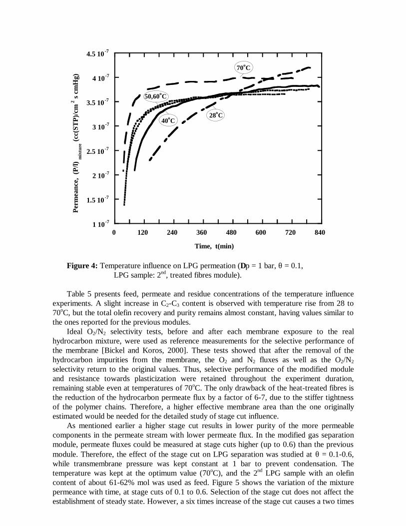
In Fig. 4, test results above 50oC show that steady state of the permeation rate is well-established after 5 h. Steady-state approach after long term permeation was also reported from other researchers [Okamoto, et al., 1997; Tanaka, et al., 1996], for the separation of C3-C4 hydrocarbons in rigid polyimides. However, a continuous increase of the permeate flux at room temperature (28oC), and a slow approach of the steady state up to 40oC were observed, probably attributed to membrane swelling due to condensation of heavier LPG hydrocarbons inside the polymer. At 1 bar applied feed pressure, i-pentane, the heaviest LPG component, is a liquid at temperatures up 48.8oC, and trans- and cis-2-butene condense near room temperature. Possible phase change of some LPG hydrocarbons at the experimental conditions, could explain why steady state is well established above 50oC. LPG permeation at 50 and 60oC seems very similar, but at 70oC the obtained permeate flux is sufficiently high and at well-established steady state behaviour.
1 10-7
1.5 10 -7
2 10-7
2.5 10 -7
3 10-7
3.5 10 -7
4 10-7
4.5 10 -7
0 120 240 360 480 600 720 840
Perm
eanc
e, (
P/l)
mix
ture
(cc(
STP)
/cm
2 s c
mH
g)
Time, t(min)
28oC
50,60oC
70oC
40oC
Figure 4: Temperature influence on LPG permeation (∆p = 1 bar, θ = 0.1,
LPG sample: 2nd, treated fibres module). Table 5 presents feed, permeate and residue concentrations of the temperature influence
experiments. A slight increase in C2-C3 content is observed with temperature rise from 28 to 70oC, but the total olefin recovery and purity remains almost constant, having values similar to the ones reported for the previous modules.
Ideal O2/N2 selectivity tests, before and after each membrane exposure to the real hydrocarbon mixture, were used as reference measurements for the selective performance of the membrane [Bickel and Koros, 2000]. These tests showed that after the removal of the hydrocarbon impurities from the membrane, the O2 and N2 fluxes as well as the O2/N2 selectivity return to the original values. Thus, selective performance of the modified module and resistance towards plasticization were retained throughout the experiment duration, remaining stable even at temperatures of 70oC. The only drawback of the heat-treated fibres is the reduction of the hydrocarbon permeate flux by a factor of 6-7, due to the stiffer tightness of the polymer chains. Therefore, a higher effective membrane area than the one originally estimated would be needed for the detailed study of stage cut influence.
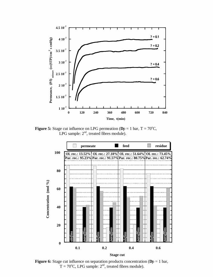
As mentioned earlier a higher stage cut results in lower purity of the more permeable components in the permeate stream with lower permeate flux. In the modified gas separation module, permeate fluxes could be measured at stage cuts higher (up to 0.6) than the previous module. Therefore, the effect of the stage cut on LPG separation was studied at θ = 0.1-0.6, while transmembrane pressure was kept constant at 1 bar to prevent condensation. The temperature was kept at the optimum value (70oC), and the 2nd LPG sample with an olefin content of about 61-62% mol was used as feed. Figure 5 shows the variation of the mixture permeance with time, at stage cuts of 0.1 to 0.6. Selection of the stage cut does not affect the establishment of steady state. However, a six times increase of the stage cut causes a two times
decrease of the permeance. The stage cut influence on LPG separation products concentration is shown in the column
chart of Figure 6. Comparing the olefin columns, it is observed that the difference in olefins concentration between the feed and the permeate is significant at low stage cuts. This difference is becoming smaller at elevated stage cuts. On the other hand, the difference in paraffin content between feed and residue becomes important at higher stage cuts. As a result, olefin recovery in the permeate increases significantly, from 13.5 to 73.5% as the stage cut varies from 0.1 to 0.6, but at the same time the olefin purity decreases, from 85 to 76 mol %. In contrast, paraffin recovery in the residue stream drops from 95.2 to 62.7% as θ increases from 0.1 to 0.6, while the paraffin residue purity increases from 41 to 60% mol. Thus, the selection of the optimal stage cut depends on the objective goal of the application. For the production of olefin rich streams a small stage cut is needed, while for the recovery of LPG isoparaffins higher stage cuts are preferable.
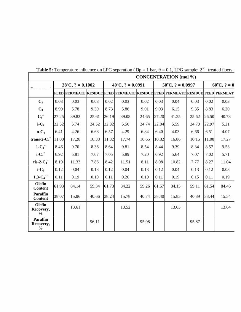
Table 5: Temperature influence on LPG separation ( ∆p = 1 bar, θ = 0.1, LPG sample: 2nd, treated fibers module)CONCENTRATION (mol %)
Component 28oC, ? = 0.1002 40oC, ? = 0.0991 50oC, ? = 0.0997 60oC, ? = 0.0994
FEED PERMEATE RESIDUE FEED PERMEATE RESIDUE FEED PERMEATE RESIDUE FEED PERMEATE
C2 0.03 0.03 0.03 0.02 0.03 0.02 0.03 0.04 0.03 0.02 0.03
C3 8.99 5.78 9.30 8.73 5.86 9.01 9.03 6.15 9.35 8.83 6.20
C3= 27.25 39.83 25.61 26.19 39.08 24.65 27.20 41.25 25.62 26.50 40.73
i-C4 22.52 5.74 24.52 22.82 5.56 24.74 22.84 5.59 24.73 22.97 5.21
n-C4 6.41 4.26 6.68 6.57 4.29 6.84 6.40 4.03 6.66 6.51 4.07
trans-2-C4= 11.00 17.28 10.33 11.32 17.74 10.65 10.82 16.86 10.15 11.08 17.27
1-C4= 8.46 9.70 8.36 8.64 9.81 8.54 8.44 9.39 8.34 8.57 9.53
i-C4= 6.92 5.81 7.07 7.05 5.89 7.20 6.92 5.64 7.07 7.02 5.71
cis-2-C4= 8.19 11.33 7.86 8.42 11.51 8.11 8.08 10.82 7.77 8.27 11.04
i-C5 0.12 0.04 0.13 0.12 0.04 0.13 0.12 0.04 0.13 0.12 0.03
1,3-C4== 0.11 0.19 0.10 0.11 0.20 0.10 0.11 0.19 0.15 0.11 0.19
Olefin Content 61.93 84.14 59.34 61.73 84.22 59.26 61.57 84.15 59.11 61.54 84.46
Paraffin Content 38.07 15.86 40.66 38.24 15.78 40.74 38.40 15.85 40.89 38.44 15.54
Olefin Recovery,
% 13.61 13.52 13.63 13.64
Paraffin Recovery,
% 96.11 95.98 95.87
1 10-7
1.5 10-7
2 10-7
2.5 10-7
3 10-7
3.5 10-7
4 10-7
4.5 10-7
0 120 240 360 480 600 720 840
Perm
eanc
e, (
P/l)
mix
ture
(cc(
STP)
/cm
2 s c
mH
g)
Time, t(min)
? = 0.1
? = 0.2
? = 0.4
? = 0.6
Figure 5: Stage cut influence on LPG permeation (∆p = 1 bar, T = 70oC,
LPG sample: 2nd, treated fibres module).
0
20
40
60
80
100
0.1 0.2 0.4 0.6
permeate feed residue
Stage cut
olef
ins
para
ffin
s
Con
cent
ratio
n (m
ol %
)
Ol. rec.: 13.52%Par. rec.: 95.23%
olef
ins
olef
ins
olef
ins
para
ffin
s
para
ffin
s
para
ffin
s
Ol. rec.: 27.18%Par. rec.: 91.57%
Ol. rec.: 51.64%Par. rec.: 80.75%
Ol. rec.: 73.45%Par. rec.: 62.74%
Figure 6: Stage cut influence on separation products concentration (∆p = 1 bar,
T = 70oC, LPG sample: 2nd, treated fibres module).
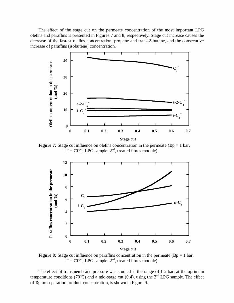
The effect of the stage cut on the permeate concentration of the most important LPG olefins and paraffins is presented in Figures 7 and 8, respectively. Stage cut increase causes the decrease of the fastest olefins concentration, propene and trans-2-butene, and the consecutive increase of paraffins (isobutene) concentration.
0
10
20
30
40
0 0.1 0.2 0.3 0.4 0.5 0.6 0.7
Ole
fins
conc
entr
atio
n in
the
perm
eate
(mol
%)
Stage cut
t-2-C4=
C3=
c-2-C4
=
1-C4=
i-C4
=
Figure 7: Stage cut influence on olefins concentration in the permeate (∆p = 1 bar,
T = 70oC, LPG sample: 2nd, treated fibres module).
0
2
4
6
8
10
12
0 0.1 0.2 0.3 0.4 0.5 0.6 0.7
Para
ffin
s co
ncen
trat
ion
in th
e pe
rmea
te(m
ol %
)
Stage cut
C3
i-C4
n-C4
Figure 8: Stage cut influence on paraffins concentration in the permeate (∆p = 1 bar,
T = 70oC, LPG sample: 2nd, treated fibres module).
The effect of transmembrane pressure was studied in the range of 1-2 bar, at the optimum temperature conditions (70oC) and a mid-stage cut (0.4), using the 2nd LPG sample. The effect of ∆p on separation product concentration, is shown in Figure 9.
0
20
40
60
80
100
1 1.5 2
permeate feed residue
Transmembrane pressure (bar)
olef
ins
Con
cent
ratio
n (m
ol %
)
Ol. recovery: 51.64 %Par. recovery: 80.75 %
olef
ins
para
ffin
s
para
ffin
s
olef
ins
para
ffin
s
Ol. recovery: 53.48%Par. recovery: 82.80 %
Ol. recovery: 54.62 %Par. recovery: 84.17 %
Figure 9: Transmembrane pressure influence on the concentration of separation products
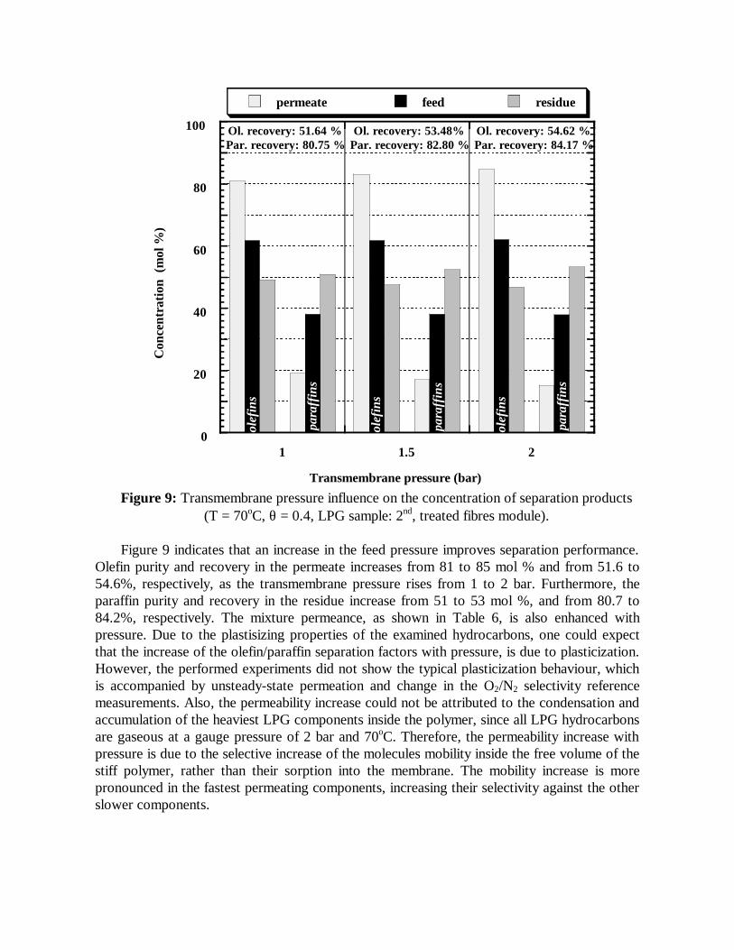
(T = 70oC, θ = 0.4, LPG sample: 2nd, treated fibres module). Figure 9 indicates that an increase in the feed pressure improves separation performance.
Olefin purity and recovery in the permeate increases from 81 to 85 mol % and from 51.6 to 54.6%, respectively, as the transmembrane pressure rises from 1 to 2 bar. Furthermore, the paraffin purity and recovery in the residue increase from 51 to 53 mol %, and from 80.7 to 84.2%, respectively. The mixture permeance, as shown in Table 6, is also enhanced with pressure. Due to the plastisizing properties of the examined hydrocarbons, one could expect that the increase of the olefin/paraffin separation factors with pressure, is due to plasticization. However, the performed experiments did not show the typical plasticization behaviour, which is accompanied by unsteady-state permeation and change in the O2/N2 selectivity reference measurements. Also, the permeability increase could not be attributed to the condensation and accumulation of the heaviest LPG components inside the polymer, since all LPG hydrocarbons are gaseous at a gauge pressure of 2 bar and 70oC. Therefore, the permeability increase with pressure is due to the selective increase of the molecules mobility inside the free volume of the stiff polymer, rather than their sorption into the membrane. The mobility increase is more pronounced in the fastest permeating components, increasing their selectivity against the other slower components.
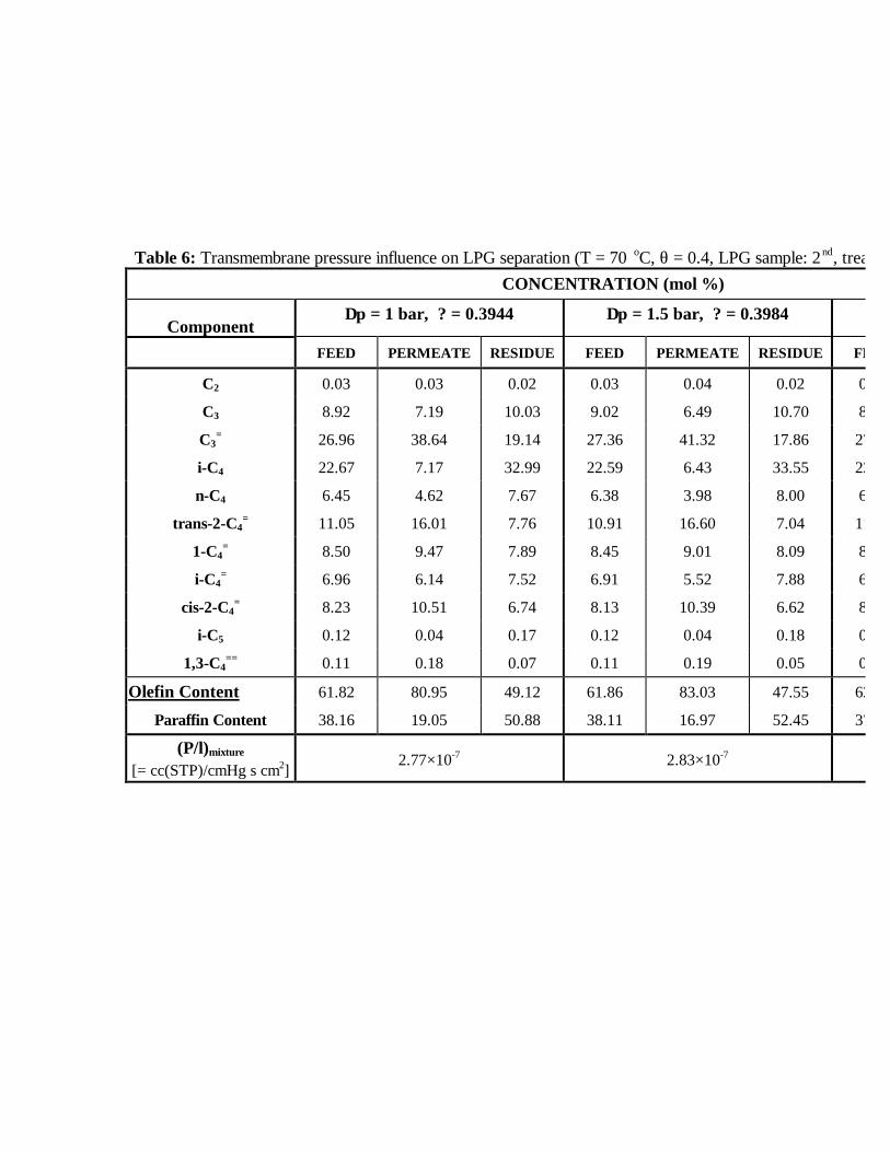
Table 6: Transmembrane pressure influence on LPG separation (T = 70 oC, θ = 0.4, LPG sample: 2nd, treated fibers module)CONCENTRATION (mol %)
Component ∆p = 1 bar, ? = 0.3944 ∆p = 1.5 bar, ? = 0.3984
FEED PERMEATE RESIDUE FEED PERMEATE RESIDUE FEED
C2 0.03 0.03 0.02 0.03 0.04 0.02 0.03
C3 8.92 7.19 10.03 9.02 6.49 10.70 8.91
C3= 26.96 38.64 19.14 27.36 41.32 17.86 27.16
i-C4 22.67 7.17 32.99 22.59 6.43 33.55 22.47
n-C4 6.45 4.62 7.67 6.38 3.98 8.00 6.43
trans-2-C4= 11.05 16.01 7.76 10.91 16.60 7.04 11.12
1-C4= 8.50 9.47 7.89 8.45 9.01 8.09 8.50
i-C4= 6.96 6.14 7.52 6.91 5.52 7.88 6.93
cis-2-C4= 8.23 10.51 6.74 8.13 10.39 6.62 8.22
i-C5 0.12 0.04 0.17 0.12 0.04 0.18 0.12
1,3-C4== 0.11 0.18 0.07 0.11 0.19 0.05 0.11
Olefin Content 61.82 80.95 49.12 61.86 83.03 47.55 62.04
Paraffin Content 38.16 19.05 50.88 38.11 16.97 52.45 37.93
(P/l)mixture [= cc(STP)/cmHg s cm2]
2.77×10⁻⁷ 2.83×10⁻⁷
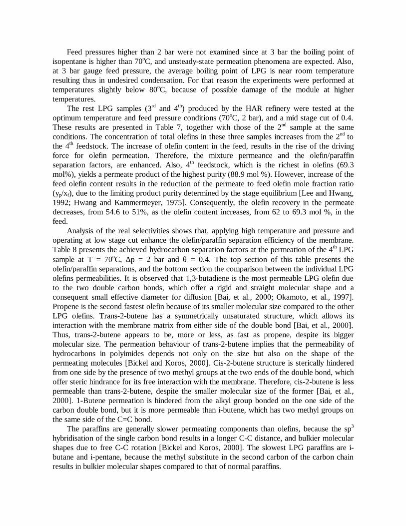
Feed pressures higher than 2 bar were not examined since at 3 bar the boiling point of isopentane is higher than 70oC, and unsteady-state permeation phenomena are expected. Also, at 3 bar gauge feed pressure, the average boiling point of LPG is near room temperature resulting thus in undesired condensation. For that reason the experiments were performed at temperatures slightly below 80oC, because of possible damage of the module at higher temperatures.
The rest LPG samples (3rd and 4th) produced by the HAR refinery were tested at the optimum temperature and feed pressure conditions (70oC, 2 bar), and a mid stage cut of 0.4. These results are presented in Table 7, together with those of the 2nd sample at the same conditions. The concentration of total olefins in these three samples increases from the 2nd to the 4th feedstock. The increase of olefin content in the feed, results in the rise of the driving force for olefin permeation. Therefore, the mixture permeance and the olefin/paraffin separation factors, are enhanced. Also, 4th feedstock, which is the richest in olefins (69.3 mol%), yields a permeate product of the highest purity (88.9 mol %). However, increase of the feed olefin content results in the reduction of the permeate to feed olefin mole fraction ratio (yp/xf), due to the limiting product purity determined by the stage equilibrium [Lee and Hwang, 1992; Hwang and Kammermeyer, 1975]. Consequently, the olefin recovery in the permeate decreases, from 54.6 to 51%, as the olefin content increases, from 62 to 69.3 mol %, in the feed.
Analysis of the real selectivities shows that, applying high temperature and pressure and operating at low stage cut enhance the olefin/paraffin separation efficiency of the membrane. Table 8 presents the achieved hydrocarbon separation factors at the permeation of the 4th LPG sample at T = 70oC, ∆p = 2 bar and θ = 0.4. The top section of this table presents the olefin/paraffin separations, and the bottom section the comparison between the individual LPG olefins permeabilities. It is observed that 1,3-butadiene is the most permeable LPG olefin due to the two double carbon bonds, which offer a rigid and straight molecular shape and a consequent small effective diameter for diffusion [Bai, et al., 2000; Okamoto, et al., 1997]. Propene is the second fastest olefin because of its smaller molecular size compared to the other LPG olefins. Trans-2-butene has a symmetrically unsaturated structure, which allows its interaction with the membrane matrix from either side of the double bond [Bai, et al., 2000]. Thus, trans-2-butene appears to be, more or less, as fast as propene, despite its bigger molecular size. The permeation behaviour of trans-2-butene implies that the permeability of hydrocarbons in polyimides depends not only on the size but also on the shape of the permeating molecules [Bickel and Koros, 2000]. Cis-2-butene structure is sterically hindered from one side by the presence of two methyl groups at the two ends of the double bond, which offer steric hindrance for its free interaction with the membrane. Therefore, cis-2-butene is less permeable than trans-2-butene, despite the smaller molecular size of the former [Bai, et al., 2000]. 1-Butene permeation is hindered from the alkyl group bonded on the one side of the carbon double bond, but it is more permeable than i-butene, which has two methyl groups on the same side of the C=C bond.
The paraffins are generally slower permeating components than olefins, because the sp3 hybridisation of the single carbon bond results in a longer C-C distance, and bulkier molecular shapes due to free C-C rotation [Bickel and Koros, 2000]. The slowest LPG paraffins are i-butane and i-pentane, because the methyl substitute in the second carbon of the carbon chain results in bulkier molecular shapes compared to that of normal paraffins.
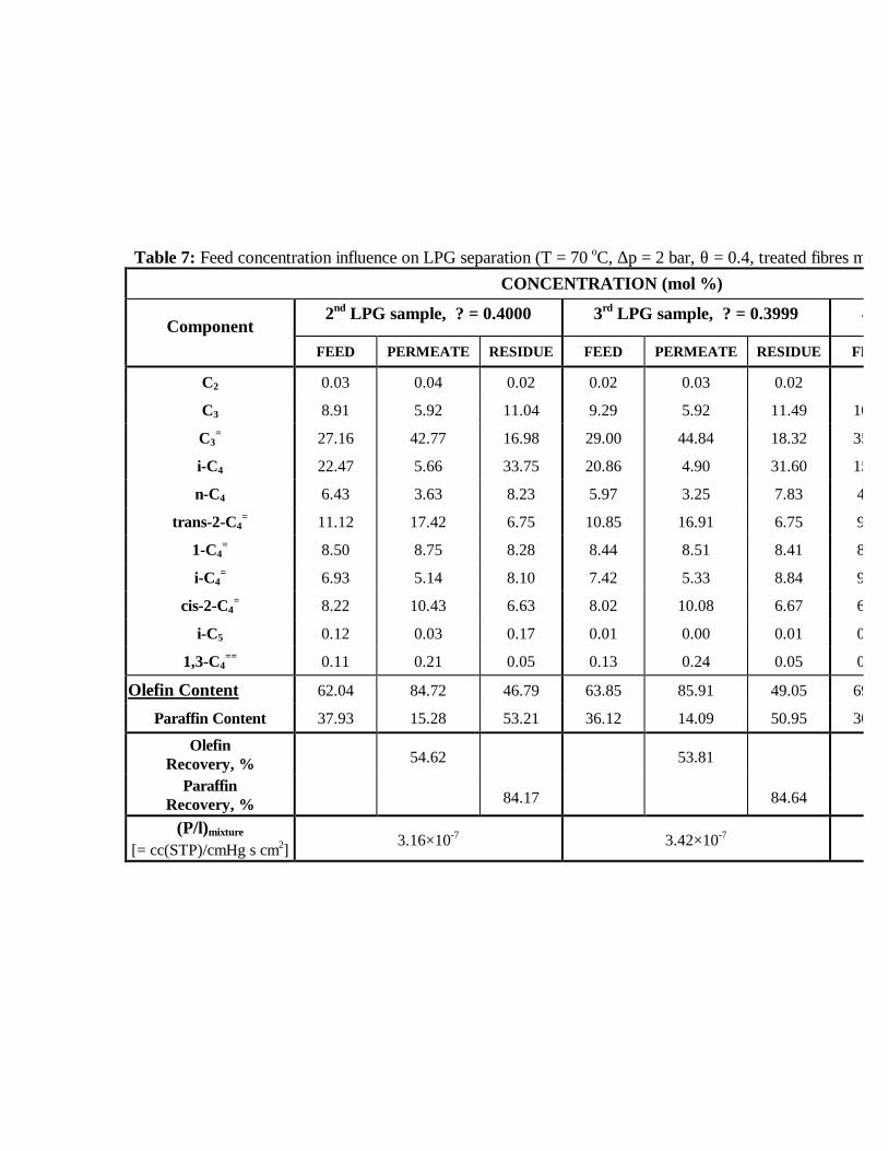
Table 7: Feed concentration influence on LPG separation (T = 70 oC, ∆p = 2 bar, θ = 0.4, treated fibres module)CONCENTRATION (mol %)
Component 2nd LPG sample, ? = 0.4000 3rd LPG sample, ? = 0.3999 4
FEED PERMEATE RESIDUE FEED PERMEATE RESIDUE FEED
C2 0.03 0.04 0.02 0.02 0.03 0.02
C3 8.91 5.92 11.04 9.29 5.92 11.49 10.17
C3= 27.16 42.77 16.98 29.00 44.84 18.32 35.45
i-C4 22.47 5.66 33.75 20.86 4.90 31.60 15.41
n-C4 6.43 3.63 8.23 5.97 3.25 7.83 4.65
trans-2-C4= 11.12 17.42 6.75 10.85 16.91 6.75 9.28
1-C4= 8.50 8.75 8.28 8.44 8.51 8.41 8.49
i-C4= 6.93 5.14 8.10 7.42 5.33 8.84 9.01
cis-2-C4= 8.22 10.43 6.63 8.02 10.08 6.67 6.73
i-C5 0.12 0.03 0.17 0.01 0.00 0.01 0.43
1,3-C4== 0.11 0.21 0.05 0.13 0.24 0.05 0.37
Olefin Content 62.04 84.72 46.79 63.85 85.91 49.05 69.34
Paraffin Content 37.93 15.28 53.21 36.12 14.09 50.95 30.66
Olefin Recovery, %
54.62 53.81
Paraffin Recovery, %
84.17 84.64
(P/l)mixture [= cc(STP)/cmHg s cm2] 3.16×10⁻⁷ 3.42×10⁻⁷
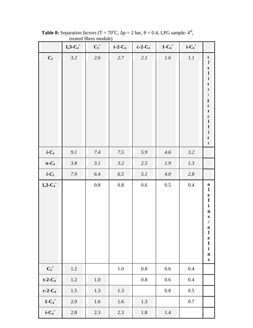
Table 8: Separation factors (T = 70oC, ∆p = 2 bar, θ = 0.4, LPG sample: 4th, treated fibres module)
1,3-C4== C3
= t-2-C4= c-2-C4
= 1-C4= i-C4
=
C3 3.2 2.6 2.7 2.1 1.6 1.1 olefins / paraffins
i-C4 9.1 7.4 7.5 5.9 4.6 3.2
n-C4 3.8 3.1 3.2 2.5 1.9 1.3
i-C5 7.9 6.4 6.5 5.1 4.0 2.8
1,3-C4== 0.8 0.8 0.6 0.5 0.4 o
lefins / olefins
C3= 1.2 1.0 0.8 0.6 0.4
t-2-C4= 1.2 1.0 0.8 0.6 0.4
c-2-C4= 1.5 1.3 1.3 0.8 0.5
1-C4= 2.0 1.6 1.6 1.3 0.7
i-C4= 2.8 2.3 2.3 1.8 1.4

Olefin/paraffin separation via pervaporation In the liquid phase olefin/paraffin separations, the prepared pervaporation modules had to
be tested using four light naphtha samples, two from the FCC pilot unit and two from the HAR refinery. As with the pilot scale gas separation experiments, the pervaporation pilot tests were performed in two membrane module types. The first module contained 336 thermally untreated hollow fibres, with a skin thickness of 0.2 µm, bonded in a SS housing with an epoxy resin. The second modified module contained 299 heat-treated hollow fibres bonded in an acrylate housing, to improve the affinity and the strength of the epoxy potting. In the second module, the fibre skin thickness was increased to 0.4 µm, enhancing the membrane strength against fluid friction. A heat treatment at 260°C for 8 min was given to fibres, to minimise membrane swelling by naphtha.
Initial experiments were performed in the first delivered pervaporation module with pure n-hexane and a simulated C5-C7 mixture, in order to establish an experimental procedure and to test module integrity. All these tests were performed at room temperature and permeate pressures up to 2.5 Torr. Hexane experiments were successful, and a permeation rate of about 3×10⁻² kg/m2 h was measured after 90 min permeation. However, the module sealing failed during the test of the C5-C7 mixture.
The second improved pervaporation module was tested by UT-CT for its thermal and chemical resistance, before delivery to CPERI. The module proved to be thermally stable at temperatures up to 70°C. A chemical stability test was performed, by flowing pure 1-hexene through the module at 50°C. Permeability measurements of O2 and N2 before and after 1-hexene experiment, showed that liquid olefins probably alter the permeation characteristics of the membrane, since the O2/N2 selectivity increased from the initial value of 6.4 to 7.4 after the experiment, and the permeation rate decreased by one half.
Initial n-hexane pervaporation tests in the second module were carried out at room temperature and 2 Torr permeate pressure. These experiments showed that the permeation rate of n-hexane was reduced at 5.5x10⁻⁴ Kg/m2 h, about fifty times lower than the corresponding flux of the first module. The reduction of permeation rate was expected to some extent, since the new module contained lower number of fibres with a twofold skin thickness. However, the significant decrease of the permeate flux, disproportionate to the change of the number of fibers and their skin thickness, is mainly due to the very stiff membrane structure because of the fiber heat treatment. Comparing the pilot tests in gas and liquid phase, it is evident that the reduction of the permeate flux due to fibre heat treatment is much more pronounced in the case of liquid hydrocarbon permeation than that of the gaseous ones, where a 6-7 times reduction was observed. Unfortunately, the low permeation rates for the liquids result in a consequent drastic decrease on the accuracy of the mass measurements of the collected permeate samples. Moreover, the approach of steady state permeation requires extremely long term tests (over one day). This reduces significantly the accuracy of the measurements because of variation of the experimental conditions (e.g. feed concentration, room temperature). In addition, any hydrocarbon impurities, remaining inside the membrane after its exposure to hydrocarbons, are very difficult to remove because of capillary flow phenomena inside the fibres.
The membrane stability to olefins was further tested in the second module, in 1-hexene pervaporation at room temperature and 1.9 Torr permeate pressure. The permeation rate of 1-hexene was about 10x10-4 Kg/m2 h, almost two times higher than that of n-hexane. After this test, O2 and N2 fluxes were further reduced by 17% without any significant change in the O2/N2 selectivity.
The separation performance of the second membrane module was examined for hydrocarbon liquid mixtures, despite the difficulty in measuring the mass flux. A light naphtha (supplied by the FCC unit) pervaporation test, carried out at room temperature and 1.4 Torr
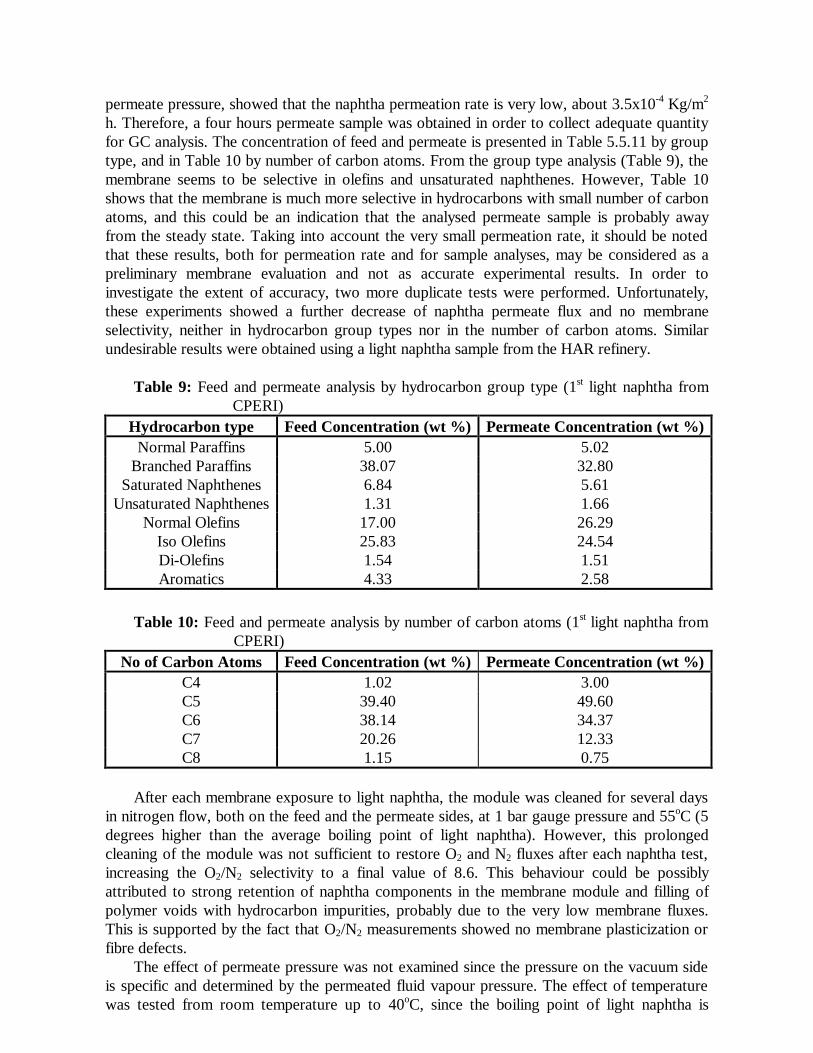
permeate pressure, showed that the naphtha permeation rate is very low, about 3.5x10⁻⁴ Kg/m2 h. Therefore, a four hours permeate sample was obtained in order to collect adequate quantity for GC analysis. The concentration of feed and permeate is presented in Table 5.5.11 by group type, and in Table 10 by number of carbon atoms. From the group type analysis (Table 9), the membrane seems to be selective in olefins and unsaturated naphthenes. However, Table 10 shows that the membrane is much more selective in hydrocarbons with small number of carbon atoms, and this could be an indication that the analysed permeate sample is probably away from the steady state. Taking into account the very small permeation rate, it should be noted that these results, both for permeation rate and for sample analyses, may be considered as a preliminary membrane evaluation and not as accurate experimental results. In order to investigate the extent of accuracy, two more duplicate tests were performed. Unfortunately, these experiments showed a further decrease of naphtha permeate flux and no membrane selectivity, neither in hydrocarbon group types nor in the number of carbon atoms. Similar undesirable results were obtained using a light naphtha sample from the HAR refinery.
Table 9: Feed and permeate analysis by hydrocarbon group type (1st light naphtha from
CPERI) Hydrocarbon type Feed Concentration (wt %) Permeate Concentration (wt %)
Normal Paraffins 5.00 5.02 Branched Paraffins 38.07 32.80
Saturated Naphthenes 6.84 5.61 Unsaturated Naphthenes 1.31 1.66
Normal Olefins 17.00 26.29 Iso Olefins 25.83 24.54 Di-Olefins 1.54 1.51 Aromatics 4.33 2.58
Table 10: Feed and permeate analysis by number of carbon atoms (1st light naphtha from
CPERI) No of Carbon Atoms Feed Concentration (wt %) Permeate Concentration (wt %)
C4 1.02 3.00 C5 39.40 49.60 C6 38.14 34.37 C7 20.26 12.33 C8 1.15 0.75
After each membrane exposure to light naphtha, the module was cleaned for several days
in nitrogen flow, both on the feed and the permeate sides, at 1 bar gauge pressure and 55oC (5 degrees higher than the average boiling point of light naphtha). However, this prolonged cleaning of the module was not sufficient to restore O2 and N2 fluxes after each naphtha test, increasing the O2/N2 selectivity to a final value of 8.6. This behaviour could be possibly attributed to strong retention of naphtha components in the membrane module and filling of polymer voids with hydrocarbon impurities, probably due to the very low membrane fluxes. This is supported by the fact that O2/N2 measurements showed no membrane plasticization or fibre defects.
The effect of permeate pressure was not examined since the pressure on the vacuum side is specific and determined by the permeated fluid vapour pressure. The effect of temperature was tested from room temperature up to 40oC, since the boiling point of light naphtha is
estimated at about 50oC. However, the heating of the liquid feed at 40oC, resulted in considerable leaks of the Viton elastomer tubing of the feed manifold, due to feed pressure increase with temperature. Taking into account, the considerable inaccuracy problems in naphtha pervaporation tests, and that a temperature increase of 10 to 15 degrees was not expected to improve significantly the membrane permselective behaviour, pervaporation tests at higher than room temperatures were not pursued further.
In conclusion, the extremely low permeation rates of the membrane and perhaps the geometry of the current hollow fibre module, do not allow the achievement of the desired olefin/paraffin separations in light naphtha pervaporation. For further study of these separations, polyimide membranes with a high free volume, and perhaps carbonised or composite polymer with zeolites, could be examined to obtain high flux, high selectivity and swelling resistance. Attention should be also paid to the hollow fibre geometry, by preparing short fibres of wide inner diameter to avoid capillary phenomena.
Process simulation and prediction of membrane performance
The modelling work of the project included the extension of the already developed models [Kaldis et al., 1998, 2000] for the description of membrane permeation phenomena in a single hollow fibre for both binary and multicomponent mixtures in order to be applied in olefin/paraffin separation. The one-dimensional, single fibre model considers the permeation of a binary and a multicomponent gas mixture through an asymmetric hollow fibre membrane with significant permeate pressure drop inside the fibre bore. Feed and permeate are assumed to flow along the fibre without radial changes of pressure, temperature, velocity or concentration. The membrane can operate in co-current or counter-current flow, with the permeate stream exiting at the same or the opposite direction of the feed, respectively. The model includes: (a) A relationship describing transport across the membrane; (b) Mass balance equations; (c) Relationships or assumptions for the pressure drop occurring on both sides of the membrane due to convective flow of the gas; (d) Boundary conditions that reflect the configuration and operation of the membrane module.
The single fibre (1-D) gas phase separation algorithms have been completed and tested for a variety of polymer materials and gas mixtures (binary and multicomponent). Results compare very well with literature experimental and theoretical data. In the present project, the models have been applied to the case of propylene/propane separation with permeability data obtained experimentally.
In the case of liquid hydrocarbons separation, a one-dimensional, single fibre model was developed for the pervaporation of a binary mixture through an asymmetric hollow fibre membrane with significant permeate pressure drop inside the fibre bore. The developed model consists also of the three basic simultaneous, first order, ordinary differential equations together with the appropriate boundary conditions, which describe the permeate production rate, the permeate concentration and the permeate pressure across the membrane length. However, in this case the permeability equation was incorporated with the use of the pore flow model [Feng and Huang, 1995) in order to account for the two phase phenomena on membrane surface. The model results were tested and found in good agreement with literature experimental and theoretical data [Feng and Huang, 1995).
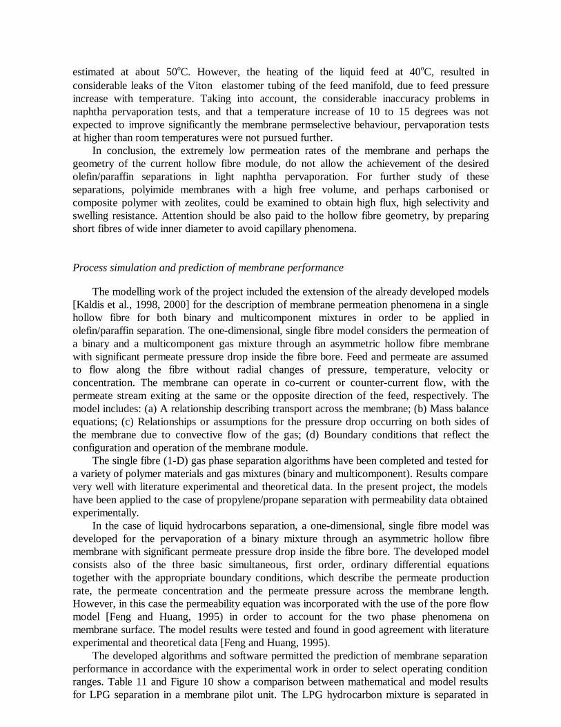
The developed algorithms and software permitted the prediction of membrane separation performance in accordance with the experimental work in order to select operating condition ranges. Table 11 and Figure 10 show a comparison between mathematical and model results for LPG separation in a membrane pilot unit. The LPG hydrocarbon mixture is separated in
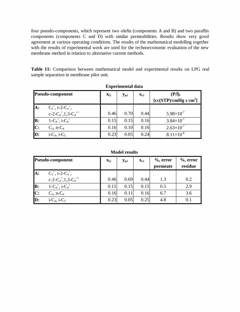
four pseudo-components, which represent two olefin (components A and B) and two paraffin components (components C and D) with similar permeabilities. Results show very good agreement at various operating conditions. The results of the mathematical modelling together with the results of experimental work are used for the technoeconomic evaluation of the new membrane method in relation to alternative current methods.
Table 11: Comparison between mathematical model and experimental results on LPG real sample separation in membrane pilot unit.
Experimental data
Pseudo-component xf,i yp,i xr,i (P/l)i
[cc(STP)/cmHg s cm2] A: C3
=, t-2-C4=,
c-2-C4=,1,3-C4
== 0.46 0.70 0.44 5.98×10⁻⁷ B: 1-C4
=, i-C4= 0.15 0.15 0.16 3.84×10⁻⁷
C: C3, n-C4 0.16 0.10 0.16 2.63×10⁻⁷ D: i-C4, i-C5 0.23 0.05 0.24 8.11×10⁻⁸
Model results
Pseudo-component xf,i yp,i xr,i %, error permeate
%, error residue
A: C3=, t-2-C4
=, c-2-C4
=,1,3-C4== 0.46 0.69 0.44 1.3 0.2
B: 1-C4=, i-C4
= 0.15 0.15 0.15 0.5 2.9 C: C3, n-C4 0.16 0.11 0.16 6.7 3.6 D: i-C4, i-C5 0.23 0.05 0.25 4.8 0.1
0
0.2
0.4
0.6
0.8
1
0
20
40
60
80
100
0 0.2 0.4 0.6 0.8 1
Stage Cut
olefin recoveryresidue
permeate
Recovery, %
Ole
fin fr
actio
n
Figure 10: LPG separation on membrane pilot unit at various stage cuts. Feed pressure 2 bars. Points: experimental, Line: model results
Based on one-dimensional codes, the study of shell-side flow on a 3-D separator model
was conducted. The binary gas separation model was implemented into version 5 of commercial CFD code FLUENT. The model is built on the mass transport and balance across a single fibre. In the 1-D simulation by Kaldis et al, 1998, the flow around the fibre (shell-side flow) was considered as uniform and the influence of shell-side flow on the separation process was not considered. The 3-D model is implemented into the CFD code FLUENT. This enables the simulation of the separation process to be done under a 3-D configuration so that the performance of a real separator can be investigated.
In CFD implementation of the gas separation model two-flow regimes need to be considered. One is the shell-side flow that originates from the feed gas mixture. The other is the permeate flow inside the fibre that originates from permeate of mixture species through the fibre membrane. For each flow regime transport of species and mass balances have to be addressed. Shell-side flow is modelled as laminar flow in porous media. The property of the porous media is determined by the fibre thickness and packing density. Due to the separation process taking place, the mass transport of species from the flow into the fibre needs to be considered.
Three cases were evaluated using the 3-D CFD code and the results show good agreement
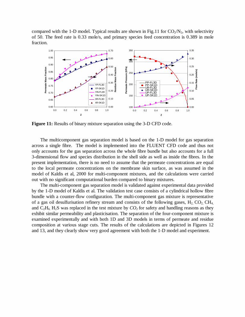
compared with the 1-D model. Typical results are shown in Fig.11 for CO2/N2, with selectivity of 50. The feed rate is 0.33 mole/s, and primary species feed concentration is 0.389 in mole fraction.
0.60
0.65
0.70
0.75
0.80
0.85
0.90
0.95
1.00
0.0 0.2 0.4 0.6 0.8 1.0
Z
Per
mea
te M
ass
Frac
tion
0.00
0.10
0.20
0.30
0.40
0.50
0.60
0.70
Res
idue
Mas
s Fr
actio
n
YP-FL3DYP-SK1DYIN-FL3DYIN-SK1DXR-FL3DXR-SK1D
100
150
200
250
300
350
0.0 0.2 0.4 0.6 0.8 1.0
Z
Per
mea
te P
ress
ure
(KP
a)
0.00
0.05
0.10
0.15
0.20
0.25
0.30
0.35
Flow
Rat
e (m
ole/
s)
PP-FL3DPP-SK1DUR-FL3DUR-SK1DUP-FL3DUP-SK1D
Figure 11: Results of binary mixture separation using the 3-D CFD code.
The multicomponent gas separation model is based on the 1-D model for gas separation
across a single fibre. The model is implemented into the FLUENT CFD code and thus not only accounts for the gas separation across the whole fibre bundle but also accounts for a full 3-dimensional flow and species distribution in the shell side as well as inside the fibres. In the present implementation, there is no need to assume that the permeate concentrations are equal to the local permeate concentrations on the membrane skin surface, as was assumed in the model of Kaldis et al, 2000 for multi-component mixtures, and the calculations were carried out with no significant computational burden compared to binary mixtures.
The multi-component gas separation model is validated against experimental data provided by the 1-D model of Kaldis et al. The validation test case consists of a cylindrical hollow fibre bundle with a counter-flow configuration. The multi-component gas mixture is representative of a gas oil desulfurisation refinery stream and consists of the following gases, H2, CO2, CH4,
and C2H6. H2S was replaced in the test mixture by CO2 for safety and handling reasons as they exhibit similar permeability and plasticisation. The separation of the four-component mixture is examined experimentally and with both 1D and 3D models in terms of permeate and residue composition at various stage cuts. The results of the calculations are depicted in Figures 12 and 13, and they clearly show very good agreement with both the 1-D model and experiment.
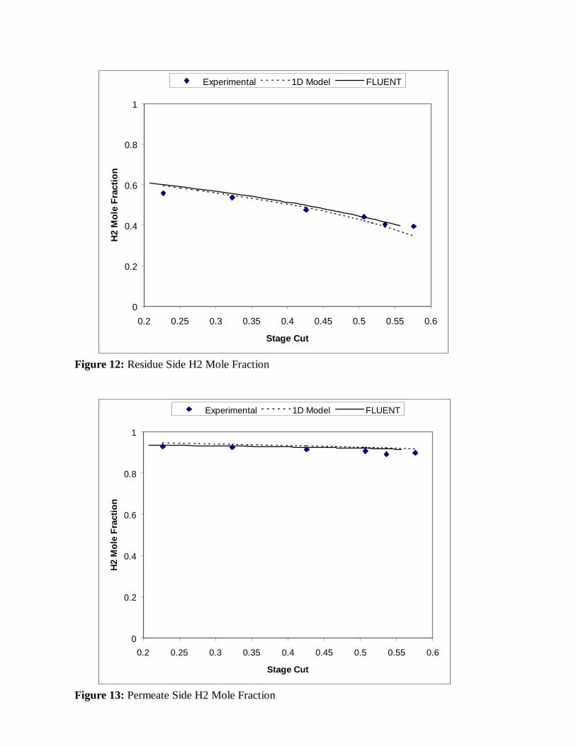
0
0.2
0.4
0.6
0.8
1
0.2 0.25 0.3 0.35 0.4 0.45 0.5 0.55 0.6
Stage Cut
H2
Mol
e Fr
actio
n
Experimental 1D Model FLUENT
Figure 12: Residue Side H2 Mole Fraction
0
0.2
0.4
0.6
0.8
1
0.2 0.25 0.3 0.35 0.4 0.45 0.5 0.55 0.6
Stage Cut
H2
Mol
e Fr
actio
n
Experimental 1D Model FLUENT
Figure 13: Permeate Side H2 Mole Fraction
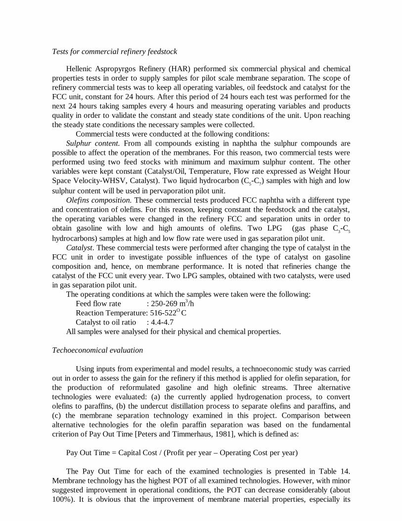
Tests for commercial refinery feedstock
Hellenic Aspropyrgos Refinery (HAR) performed six commercial physical and chemical properties tests in order to supply samples for pilot scale membrane separation. The scope of refinery commercial tests was to keep all operating variables, oil feedstock and catalyst for the FCC unit, constant for 24 hours. After this period of 24 hours each test was performed for the next 24 hours taking samples every 4 hours and measuring operating variables and products quality in order to validate the constant and steady state conditions of the unit. Upon reaching the steady state conditions the necessary samples were collected.
Commercial tests were conducted at the following conditions: Sulphur content. From all compounds existing in naphtha the sulphur compounds are
possible to affect the operation of the membranes. For this reason, two commercial tests were performed using two feed stocks with minimum and maximum sulphur content. The other variables were kept constant (Catalyst/Oil, Temperature, Flow rate expressed as Weight Hour Space Velocity-WHSV, Catalyst). Two liquid hydrocarbon (C5-C7) samples with high and low sulphur content will be used in pervaporation pilot unit.
Olefins composition. These commercial tests produced FCC naphtha with a different type and concentration of olefins. For this reason, keeping constant the feedstock and the catalyst, the operating variables were changed in the refinery FCC and separation units in order to obtain gasoline with low and high amounts of olefins. Two LPG (gas phase C3-C5 hydrocarbons) samples at high and low flow rate were used in gas separation pilot unit.
Catalyst. These commercial tests were performed after changing the type of catalyst in the FCC unit in order to investigate possible influences of the type of catalyst on gasoline composition and, hence, on membrane performance. It is noted that refineries change the catalyst of the FCC unit every year. Two LPG samples, obtained with two catalysts, were used in gas separation pilot unit.
The operating conditions at which the samples were taken were the following: Feed flow rate : 250-269 m3/h Reaction Temperature: 516-522O C Catalyst to oil ratio : 4.4-4.7 All samples were analysed for their physical and chemical properties.
Techoeconomical evaluation Using inputs from experimental and model results, a technoeconomic study was carried
out in order to assess the gain for the refinery if this method is applied for olefin separation, for the production of reformulated gasoline and high olefinic streams. Three alternative technologies were evaluated: (a) the currently applied hydrogenation process, to convert olefins to paraffins, (b) the undercut distillation process to separate olefins and paraffins, and (c) the membrane separation technology examined in this project. Comparison between alternative technologies for the olefin paraffin separation was based on the fundamental criterion of Pay Out Time [Peters and Timmerhaus, 1981], which is defined as:
Pay Out Time = Capital Cost / (Profit per year – Operating Cost per year) The Pay Out Time for each of the examined technologies is presented in Table 14.
Membrane technology has the highest POT of all examined technologies. However, with minor suggested improvement in operational conditions, the POT can decrease considerably (about 100%). It is obvious that the improvement of membrane material properties, especially its
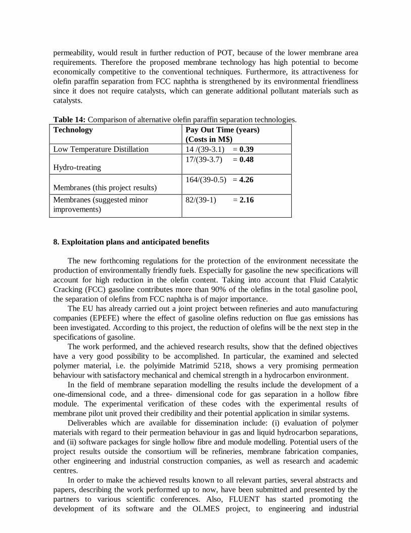
permeability, would result in further reduction of POT, because of the lower membrane area requirements. Therefore the proposed membrane technology has high potential to become economically competitive to the conventional techniques. Furthermore, its attractiveness for olefin paraffin separation from FCC naphtha is strengthened by its environmental friendliness since it does not require catalysts, which can generate additional pollutant materials such as catalysts.
Table 14: Comparison of alternative olefin paraffin separation technologies. Technology Pay Out Time (years)
(Costs in M$) Low Temperature Distillation 14 /(39-3.1) = 0.39
Hydro-treating 17/(39-3.7) = 0.48
Membranes (this project results) 164/(39-0.5) = 4.26
Membranes (suggested minor improvements)
82/(39-1) = 2.16
8. Exploitation plans and anticipated benefits
The new forthcoming regulations for the protection of the environment necessitate the production of environmentally friendly fuels. Especially for gasoline the new specifications will account for high reduction in the olefin content. Taking into account that Fluid Catalytic Cracking (FCC) gasoline contributes more than 90% of the olefins in the total gasoline pool, the separation of olefins from FCC naphtha is of major importance.
The EU has already carried out a joint project between refineries and auto manufacturing companies (EPEFE) where the effect of gasoline olefins reduction on flue gas emissions has been investigated. According to this project, the reduction of olefins will be the next step in the specifications of gasoline.
The work performed, and the achieved research results, show that the defined objectives have a very good possibility to be accomplished. In particular, the examined and selected polymer material, i.e. the polyimide Matrimid 5218, shows a very promising permeation behaviour with satisfactory mechanical and chemical strength in a hydrocarbon environment.
In the field of membrane separation modelling the results include the development of a one-dimensional code, and a three- dimensional code for gas separation in a hollow fibre module. The experimental verification of these codes with the experimental results of membrane pilot unit proved their credibility and their potential application in similar systems.
Deliverables which are available for dissemination include: (i) evaluation of polymer materials with regard to their permeation behaviour in gas and liquid hydrocarbon separations, and (ii) software packages for single hollow fibre and module modelling. Potential users of the project results outside the consortium will be refineries, membrane fabrication companies, other engineering and industrial construction companies, as well as research and academic centres.
In order to make the achieved results known to all relevant parties, several abstracts and papers, describing the work performed up to now, have been submitted and presented by the partners to various scientific conferences. Also, FLUENT has started promoting the development of its software and the OLMES project, to engineering and industrial
construction companies and other potential users of its technology, by means of a technical leaflet.
The partners are examining also, other possible exploitation measures, such as diffusion activities to industries and engineering design companies, publications to scientific and technical journals, seminars etc. Licensing of technology to third parties will be considered on a case-by-case basis. It must be noted that none of the partners has an existing or anticipated agreement or commitment, which could impose a limitation on the subsequent exploitation of inventions generated as a result of this research. REFERENCES
Bai S., Sridhar, S., and Khan, A.A., J. Membrane Sci. 174 (2000) 67. Bickel C.S., and Koros W.J., J. Membrane Sci. 170 (2000) 205. Feng X., and Huang, R.Y.M., Ind. Eng. Chem. Res., 36 (1997) 1048. Feng, X., and Huang, R., Can. J. Chem. Eng., 73 (1995) 833. Hwang S.T., and Kammermeyer K., “Membranes in Separations”, Vol.VII, John Wiley and
Sons, Inc., New York, 1975, ch.4-5. Kaldis, S.P., Kapantaidakis, G.C., Papadopoulos, T.I., and Sakellaropoulos, G.P., J.
Membrane Sci., 142 (1998) 43. Kaldis, S.P., Kapantaidakis, G.C., and Sakellaropoulos, G.P., J. Membrane Sci., 173 (2000)
61. Lee, K.R., and Hwang, S.T., J. Membrane Sci., 73 (1992) 37. Okamoto, K., Noborio, K., Hao, J., Tanaka, K., and Kita, H., J. Membrane Sci., 134 (1997)
171. Peters, M.S., and Timmerhaus, K.D., Plant Design and Economics for Chemical Engineers, 3rd
Edition, McGraw-Hill, 1981. Tanaka, K., Taguchi, A., Hao, J., Kita, H., and Okamoto, K., J. Membrane Sci., 121 (1996)
197.