Embed Size (px)
Citation preview
www.cnr.it
Membrane engineering for CO2 separation by gas separation systems
Adele Brunetti1, Alessio Caravella1, Giuseppe Barbieri1,
Young Mo Lee3, Enrico Drioli1,2,3
3° Trondheim Gas Technology Conference (TGTC-3) June 4th-5th, 2014
1 - National Research Council - Institute for Membrane Technology (ITM–CNR)
Via Pietro BUCCI, c/o The University of Calabria, cubo 17C, 87036 Rende CS, Italy. www.itm.cnr.it
2 - The University of Calabria - Department of Chemical Engineering and Materials
Via Pietro BUCCI, cubo 44A - 87036 Rende CS, Italy
3 - Hanyang University, WCU Energy Engineering Department, Seongdong-gu, Seoul 133-791, South Korea
www.cnr.it
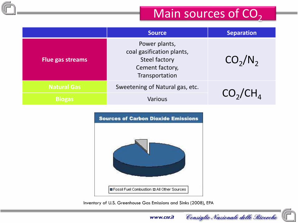
Main sources of CO2
Source Separation
Flue gas streams
Power plants, coal gasification plants,
Steel factory Cement factory, Transportation
CO2/N2
Natural Gas Sweetening of Natural gas, etc. CO2/CH4 Biogas Various
Inventory of U.S. Greenhouse Gas Emissions and Sinks (2008), EPA
www.cnr.it
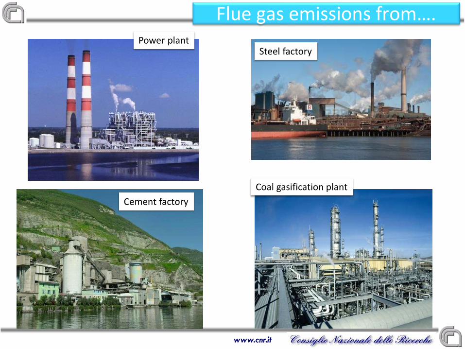
Flue gas emissions from…. Power plant
Steel factory
Cement factory
Coal gasification plant
www.cnr.it
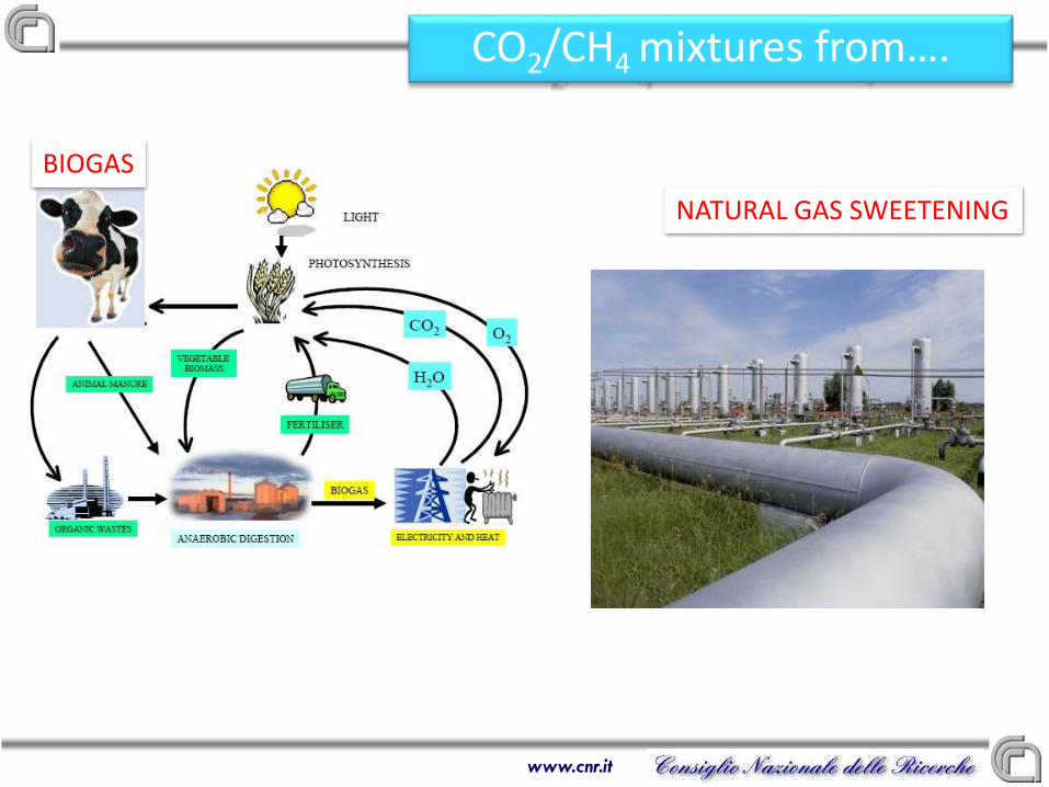
CO2/CH4 mixtures from….
BIOGAS
NATURAL GAS SWEETENING
www.cnr.it
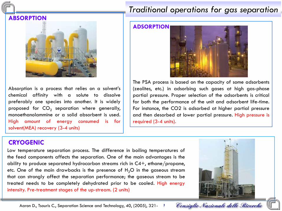
Traditional operations for gas separation
Aaron D., Tsouris C., Separation Science and Technology, 40, (2005), 321-
ABSORPTION
Absorption is a process that relies on a solvent’s
chemical affinity with a solute to dissolve
preferably one species into another. It is widely
proposed for CO2 separation where generally,
monoethanolammine or a solid absorbent is used.
High amount of energy consumed is for
solvent(MEA) recovery (3-4 units)
ADSORPTION
The PSA process is based on the capacity of some adsorbents
(zeolites, etc.) in adsorbing such gases at high gas-phase
partial pressure. Proper selection of the adsorbents is critical
for both the performance of the unit and adsorbent life-time.
For instance, the CO2 is adsorbed at higher partial pressure
and then desorbed at lower partial pressure. High pressure is
required (3-4 units).
Low temperature separation process. The difference in boiling temperatures of
the feed components affects the separation. One of the main advantages is the
ability to produce separated hydrocarbon streams rich in C4+, ethane/propane,
etc. One of the main drawbacks is the presence of H2O in the gaseous stream
that can strongly affect the separation performance; the gaseous stream to be
treated needs to be completely dehydrated prior to be cooled. High energy
intensity. Pre-treatment stages of the up-stream. (2 units)
CRYOGENIC
www.cnr.it
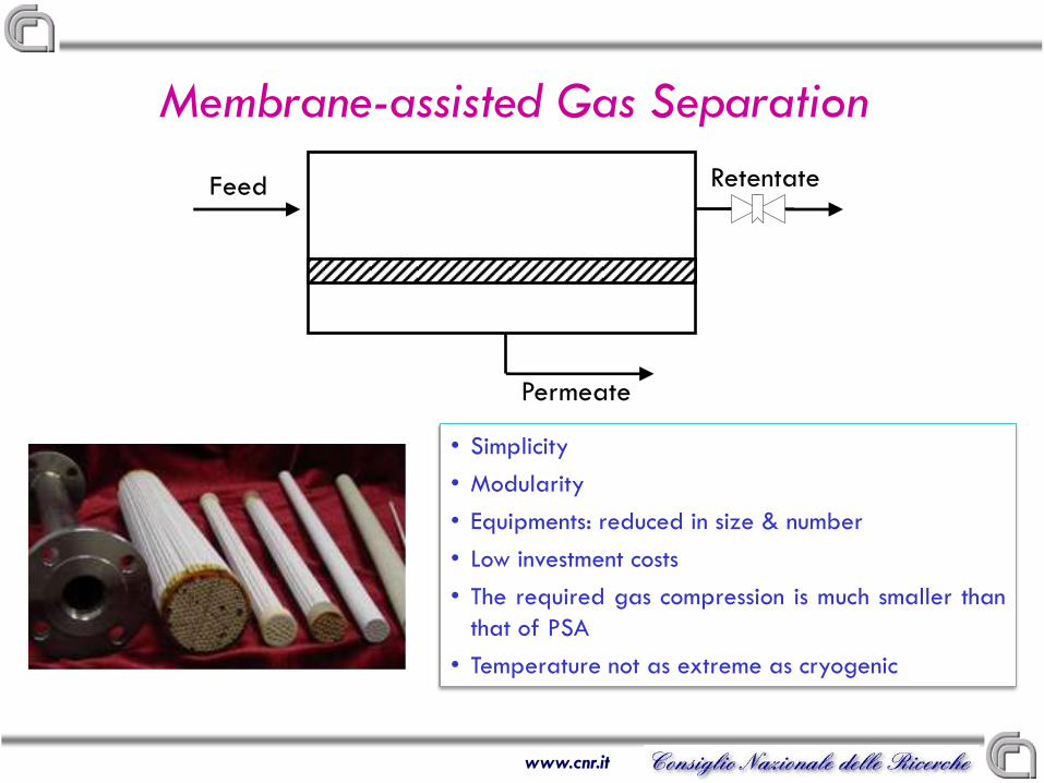
Membrane-assisted Gas Separation
• Simplicity
• Modularity
• Equipments: reduced in size & number
• Low investment costs
• The required gas compression is much smaller than
that of PSA
• Temperature not as extreme as cryogenic
1800 m2
One stage plant
1.2X10⁶ Nm3/h
10%CO2
55 bar
2% CO2
44% CO2
1.7 bar
Use for fuel or flare
Feed
Permeate
Retentate
www.cnr.it
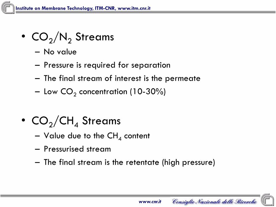
• CO2/N2 Streams
– No value
– Pressure is required for separation
– The final stream of interest is the permeate
– Low CO2 concentration (10-30%)
• CO2/CH4 Streams
– Value due to the CH4 content
– Pressurised stream
– The final stream is the retentate (high pressure)
Institute on Membrane Technology, ITM-CNR, www.itm.cnr.it
www.cnr.it
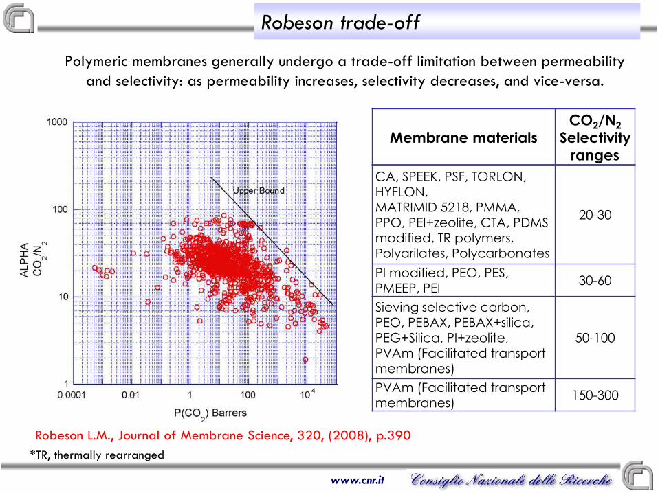
Robeson trade-off
Polymeric membranes generally undergo a trade-off limitation between permeability
and selectivity: as permeability increases, selectivity decreases, and vice-versa.
Robeson L.M., Journal of Membrane Science, 320, (2008), p.390
*TR, thermally rearranged
Membrane materials
CO2/N2
Selectivity
ranges
CA, SPEEK, PSF, TORLON, HYFLON, MATRIMID 5218, PMMA, PPO, PEI+zeolite, CTA, PDMS
modified, TR polymers, Polyarilates, Polycarbonates
20-30
PI modified, PEO, PES,
PMEEP, PEI 30-60
Sieving selective carbon, PEO, PEBAX, PEBAX+silica, PEG+Silica, PI+zeolite, PVAm (Facilitated transport
membranes)
50-100
PVAm (Facilitated transport membranes)
150-300
www.cnr.it
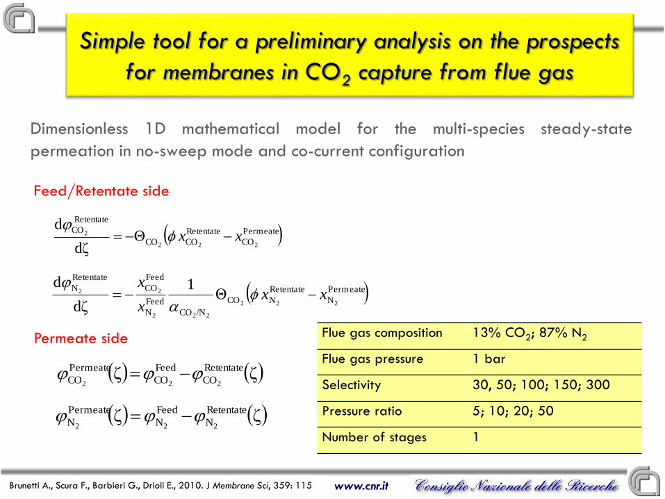
Simple tool for a preliminary analysis on the prospects
for membranes in CO2 capture from flue gas
Dimensionless 1D mathematical model for the multi-species steady-state
permeation in no-sweep mode and co-current configuration
Feed/Retentate side
Permeate side
Permeate
CO
Retentate
COCO
Retentate
CO
222
2 Θdζ
dxx
Permeate
N
Retentate
NCO
/NCO
Feed
N
Feed
CO
Retentate
N
222
222
22 Θ1
dζ
dxx
x
x
ζζ Retentate
CO
Feed
CO
Permeate
CO 222
ζζ Retentate
N
Feed
N
Permeate
N 222
Brunetti A., Scura F., Barbieri G., Drioli E., 2010. J Membrane Sci, 359: 115
Flue gas composition 13% CO2; 87% N2
Flue gas pressure 1 bar
Selectivity 30, 50; 100; 150; 300
Pressure ratio 5; 10; 20; 50
Number of stages 1
www.cnr.it
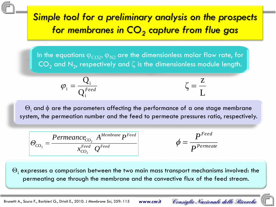
Simple tool for a preliminary analysis on the prospects
for membranes in CO2 capture from flue gas
In the equations CO2, N2 are the dimensionless molar flow rate, for
CO2 and N2, respectively and z is the dimensionless module length.
Feed
i
ii
Q
Q
L
zζ
Qi and are the parameters affecting the performance of a one stage membrane
system, the permeation number and the feed to permeate pressures ratio, respectively.
FeedFeed
CO
FeedMembrane
CO
COQx
PAPermeanceΘ
2
2
2
Permeate
Feed
P
P
Qi expresses a comparison between the two main mass transport mechanisms involved: the
permeating one through the membrane and the convective flux of the feed stream.
Brunetti A., Scura F., Barbieri G., Drioli E., 2010. J Membrane Sci, 359: 115
www.cnr.it
0 20 40 60 80 100
CO2 recovery index, %
0
20
40
60
80
100
CO
2 p
erm
eate
pu
rity
, %Q
CO2=1
0.05
0.1
0.5
0.2
=510 20
50
CO2/N2=30
C
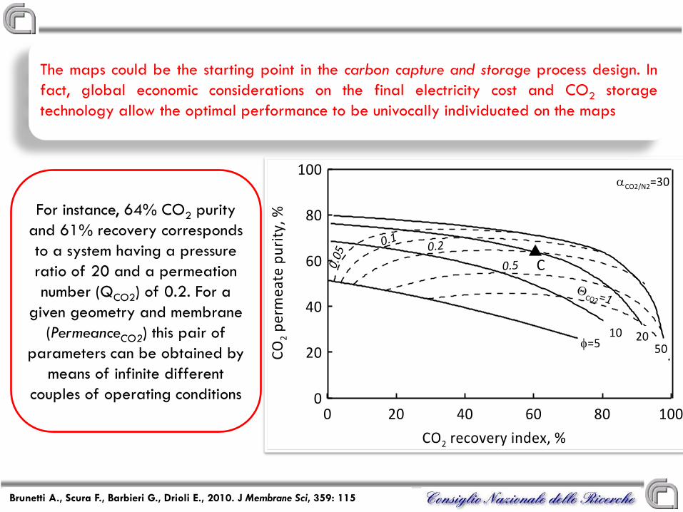
The maps could be the starting point in the carbon capture and storage process design. In
fact, global economic considerations on the final electricity cost and CO2 storage
technology allow the optimal performance to be univocally individuated on the maps
For instance, 64% CO2 purity
and 61% recovery corresponds
to a system having a pressure
ratio of 20 and a permeation
number (QCO2) of 0.2. For a
given geometry and membrane
(PermeanceCO2) this pair of
parameters can be obtained by
means of infinite different
couples of operating conditions
Brunetti A., Scura F., Barbieri G., Drioli E., 2010. J Membrane Sci, 359: 115
www.cnr.it
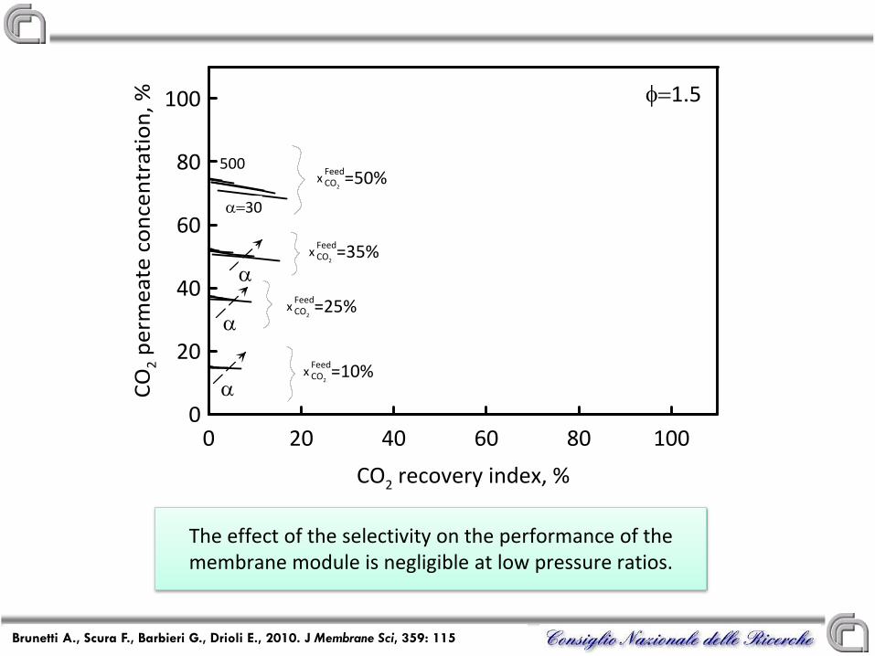
The effect of the selectivity on the performance of the membrane module is negligible at low pressure ratios.
Brunetti A., Scura F., Barbieri G., Drioli E., 2010. J Membrane Sci, 359: 115
www.cnr.it
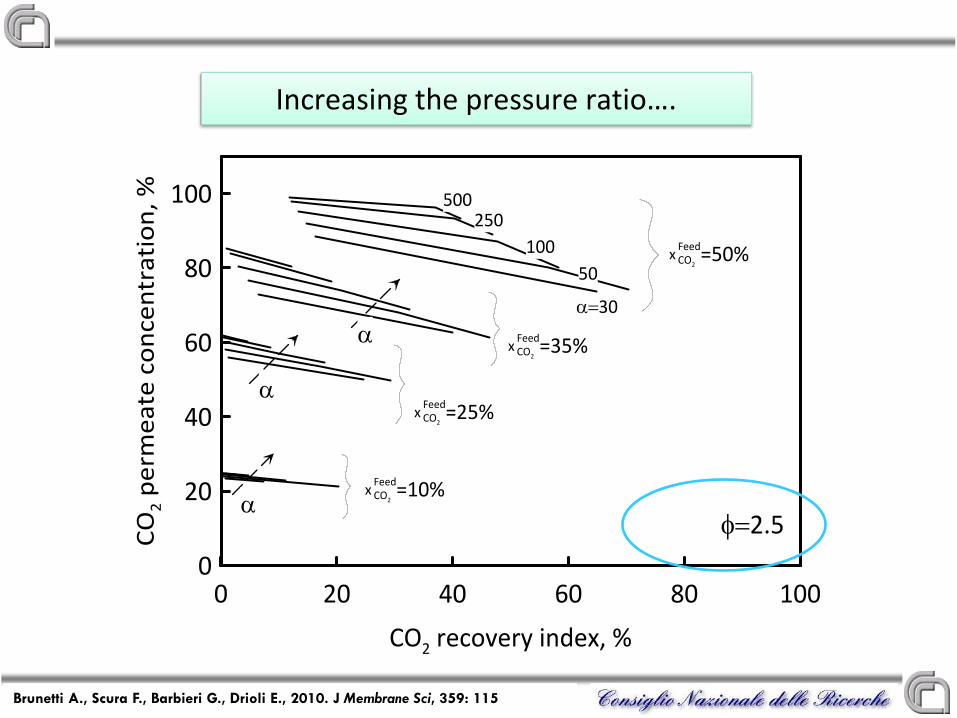
Increasing the pressure ratio….
Brunetti A., Scura F., Barbieri G., Drioli E., 2010. J Membrane Sci, 359: 115
www.cnr.it
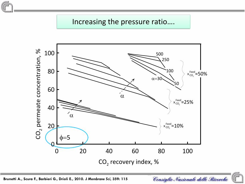
Increasing the pressure ratio….
Brunetti A., Scura F., Barbieri G., Drioli E., 2010. J Membrane Sci, 359: 115
www.cnr.it
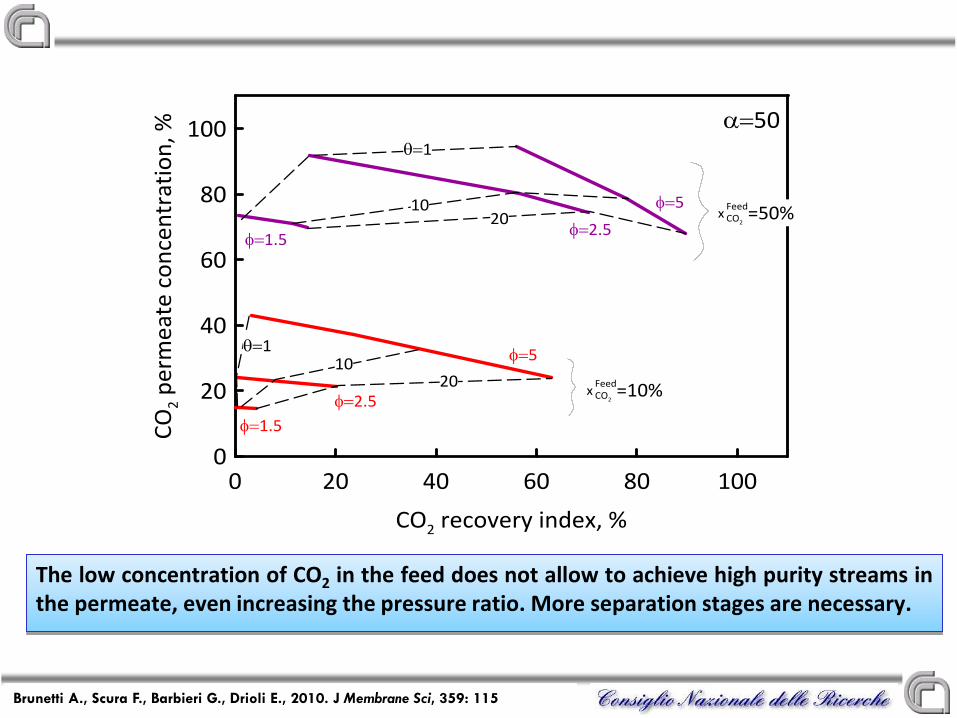
The low concentration of CO2 in the feed does not allow to achieve high purity streams in the permeate, even increasing the pressure ratio. More separation stages are necessary.
Brunetti A., Scura F., Barbieri G., Drioli E., 2010. J Membrane Sci, 359: 115
www.cnr.it
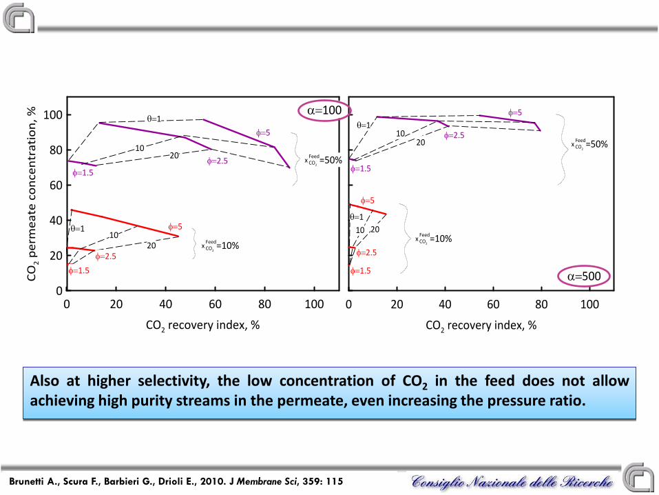
Also at higher selectivity, the low concentration of CO2 in the feed does not allow achieving high purity streams in the permeate, even increasing the pressure ratio.
Brunetti A., Scura F., Barbieri G., Drioli E., 2010. J Membrane Sci, 359: 115
www.cnr.it
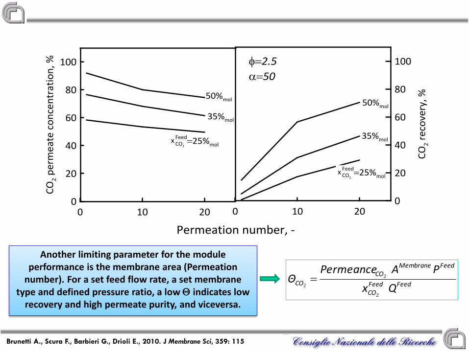
Another limiting parameter for the module performance is the membrane area (Permeation
number). For a set feed flow rate, a set membrane type and defined pressure ratio, a low Q indicates low
recovery and high permeate purity, and viceversa.
FeedFeedCO
FeedMembraneCO
COQx
PAPermeanceΘ
2
2
2
Brunetti A., Scura F., Barbieri G., Drioli E., 2010. J Membrane Sci, 359: 115
www.cnr.it
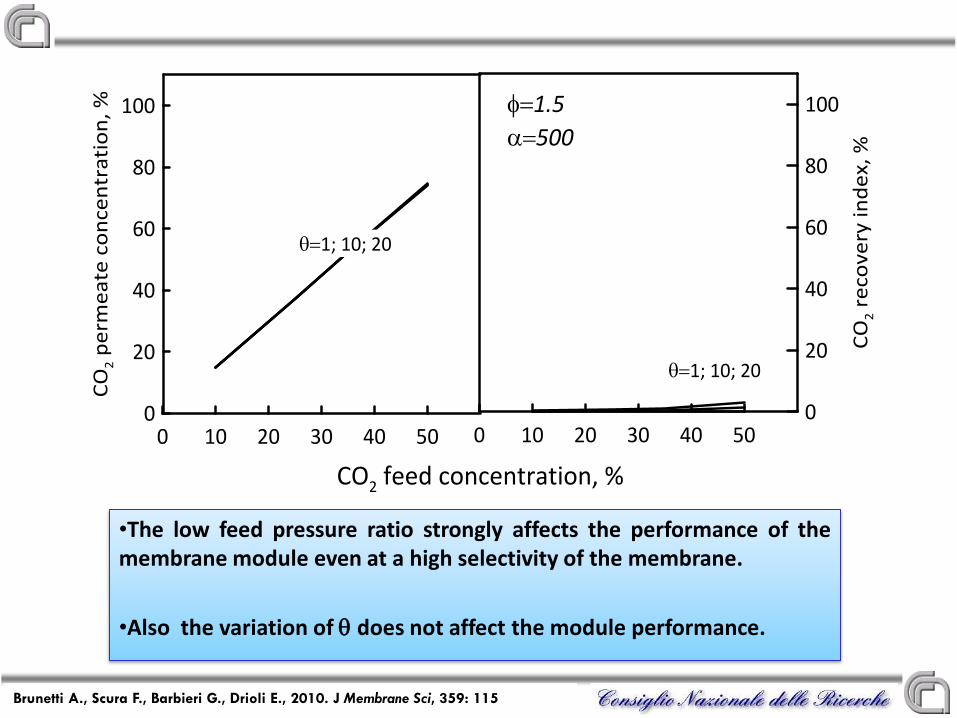
•The low feed pressure ratio strongly affects the performance of the membrane module even at a high selectivity of the membrane.
•Also the variation of q does not affect the module performance.
Brunetti A., Scura F., Barbieri G., Drioli E., 2010. J Membrane Sci, 359: 115
www.cnr.it
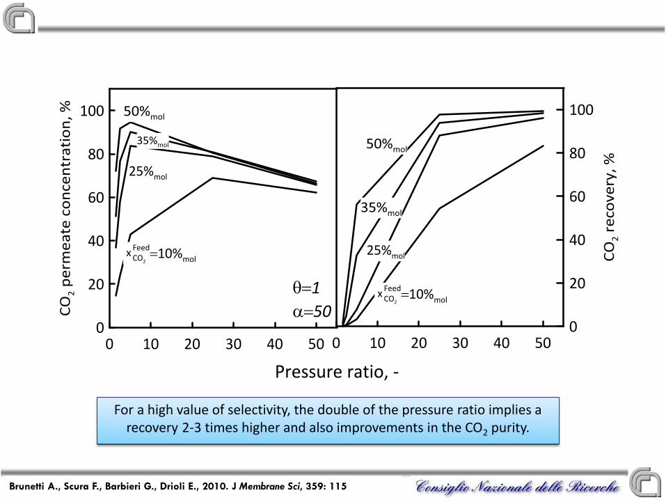
For a high value of selectivity, the double of the pressure ratio implies a recovery 2-3 times higher and also improvements in the CO2 purity.
Brunetti A., Scura F., Barbieri G., Drioli E., 2010. J Membrane Sci, 359: 115
www.cnr.it
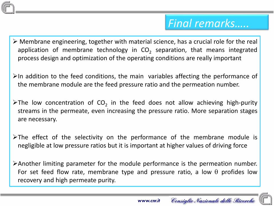
Final remarks…..
Membrane engineering, together with material science, has a crucial role for the real application of membrane technology in CO2 separation, that means integrated process design and optimization of the operating conditions are really important
In addition to the feed conditions, the main variables affecting the performance of the membrane module are the feed pressure ratio and the permeation number.
The low concentration of CO2 in the feed does not allow achieving high-purity streams in the permeate, even increasing the pressure ratio. More separation stages are necessary.
The effect of the selectivity on the performance of the membrane module is negligible at low pressure ratios but it is important at higher values of driving force
Another limiting parameter for the module performance is the permeation number. For set feed flow rate, membrane type and pressure ratio, a low q profides low recovery and high permeate purity.
www.cnr.it
ITM-CNR
Padova
UOS
ITM – Rende
Headquarter
National Research Council – Institute on Membrane Technology www.itm.cnr.it
c/o University of Calabria, Via Pietro BUCCI, 17/C, I-87030 Rende CS, Italy
Tel. +39 0984-492050; Fax. +39 0984-402103