Embed Size (px)
Citation preview


a
Member (River Management) Central Water Commission
& Ex-Officio Additional Secretary
to the Government of India Room No 212(S), Sewa Bhawan R. K. Puram, New Delhi-110066
FOREWORD
India is one of the most flood-affected countries in the world. There is not a single year when some or the other part of the country does not get inundated during floods.
The floods are now considered as natural disaster. But unlike other natural disasters such as, earthquakes, landslides, etc, it is possible to manage floods to a great extent. As widely known, there are two options for flood management viz. structural measures & non-structural measures. The modern flood management strategy is a judicious mixture of both options.
This Handbook has been brought out to provide necessary guidance to the field engineers to deal primarily with structural measures of flood management like flood protection works, anti erosion measures and river training works. The handbook deliberates on planning, design and monitoring of various flood protection, anti erosion and river training works along with use of new construction materials which are integral part of any project. I am sure that this handbook would provide all relevant information at one place to the practicing Engineers dealing with flood management works for ready reference.
I place on record the inspiring leadership of Sh K. N. Keshri, Chief Engineer (Flood Management) for guiding the team to bring out such a useful publication in flood control sector.
(S. P. Kakran)
New Delhi June, 2012

b
Chief Engineer Flood Management Organisation
Central Water Commission New Delhi
PREFACE
India has peculiar geographical features experiencing flood in some parts and drought in other parts and sometimes they co-exist.
India has made huge investment in flood control sector since 1951 in implementing number of flood management schemes which has undoubtedly provided great relief to a large population against floods.
The Engineers involved in framing the project report and subsequent implementation for flood protection, anti-erosion and river training works need a handbook for having a comprehensive view of design principles, construction techniques and costing thereof.
This handbook containing details of construction materials, guidelines for design embankment, bank revetment, spurs/groynes, RCC porcupines, drainage improvement works, Construction methodology, cost estimate and unit rate analysis would provide a ready reference to plan, construct and monitor the flood management projects in an integrated manner.
I place on record the outstanding efforts made by officials of
Flood Management-II Directorate specially Sh A K Kharya, Director and Sh Piyush Kumar, Dy Director in preparation of this handbook.
Any suggestion for improvement of the contents will be highly
appreciated.
(K. N. Keshri)
New Delhi June 2012
i
Contents
Contents ...................................................................................................... i
List of Tables ............................................................................................... vi
List of Figures ............................................................................................ vii
Abbreviations and Common Terms ............................................................. ix
1.0 Introduction .................................................................................... 1 1.1 General .................................................................................................................................... 1 1.2 Flood damages in India ......................................................................................................... 2 1.3 Flood prone areas in the country ......................................................................................... 4 1.4 Flood Management Programme ........................................................................................... 4
1.4.1 Salient features of FMP ........................................................................................... 4 1.4.2 Funds released under FMP ...................................................................................... 5
1.5 Working Group on "Flood Management and Region Specific Issues" ............................... 5 1.6 Measures for flood management and erosion control ........................................................ 5
1.6.1 Non-structural measures ......................................................................................... 5 1.6.2 Structural measures ................................................................................................ 6
1.7 References ............................................................................................................................... 6
2.0 Construction Materials .................................................................... 7 2.1 General .................................................................................................................................... 7 2.2 Type of construction materials ............................................................................................. 7
2.2.1 River bed materials .................................................................................................. 7 2.2.2 GI wire mesh ............................................................................................................ 8 2.2.3 Revet-mattress ........................................................................................................ 8 2.2.4 Concrete blocks ....................................................................................................... 8 2.2.5 Reinforced cement concrete porcupines ................................................................ 9 2.2.6 Geo-synthetics ......................................................................................................... 9
2.3 Technical specifications of construction materials and testing ....................................... 12 2.3.1 Wire mesh gabions ................................................................................................ 12 2.3.2 Geo-textile as filter ................................................................................................ 15 2.3.3 Geo-textile bags. ................................................................................................... 16 2.3.4 Geo-textile tubes ................................................................................................... 17 2.3.5 Vetiver for bank protection ................................................................................... 18
2.4 References ............................................................................................................................ 18
3.0 Design of Flood Embankment ........................................................ 19 3.1 General. ................................................................................................................................ 19 3.2 Planning of embankments. ................................................................................................. 19
3.2.1 Classification .......................................................................................................... 19 3.2.2 Requirement of data. ............................................................................................ 20 3.2.3 Degree of protection. ............................................................................................ 20 3.2.4 Alignment & spacing of embankment................................................................... 21
3.3 Design of embankment ........................................................................................................ 22 3.3.1 Types. .................................................................................................................... 22

ii
3.3.2 Design HFL. ............................................................................................................ 23 3.3.3 Free board ............................................................................................................. 24 3.3.4 Top width ............................................................................................................... 24 3.3.5 Hydraulic gradient ................................................................................................. 25 3.3.6 Side slope ............................................................................................................... 25 3.3.7 Drainage ................................................................................................................ 27 3.3.8 Safety measures in design ..................................................................................... 28 3.3.9 Sluices .................................................................................................................... 28 3.3.10 Causes of failure of embankment ......................................................................... 28 3.3.11 Preventive measures ............................................................................................. 29 3.3.12 Closure of breach................................................................................................... 29 3.3.13 Protection of embankment ................................................................................... 29
3.4 Stability analysis for high embankments ........................................................................... 30 3.4.1 Selection of design parameters ............................................................................. 31 3.4.2 Analysis procedure ................................................................................................ 31 3.4.3 Stability computation ............................................................................................ 31 3.4.4 Final selection of embankment section ................................................................ 31 3.4.5 Defensive design measures ................................................................................... 32
3.5 Merits and demerits of embankments ............................................................................... 32 3.5.1 Merits .................................................................................................................... 32 3.5.2 Demerits ................................................................................................................ 32
3.6 References ............................................................................................................................ 33
4.0 Design of Bank Revetment ............................................................. 34 4.1 General .................................................................................................................................. 34 4.2 Causes of bank failures ........................................................................................................ 34 4.3 Methods of bank protection: ............................................................................................... 35
4.3.1 Vetivers .................................................................................................................. 36 4.3.2 Submerged vanes .................................................................................................. 36 4.3.3 RCC kellener Jettys ................................................................................................ 37 4.3.4 Geo-cell .................................................................................................................. 37
4.4 Planning of bank revetment ................................................................................................ 38 4.4.2 Degree of protection ............................................................................................. 40
4.5 Design of bank revetment ................................................................................................... 40 4.5.1 Weight of stones/ boulders ................................................................................... 40 4.5.2 Size of stone/ boulder ........................................................................................... 41 4.5.3 Thickness of pitching ............................................................................................. 41 4.5.4 Filter ....................................................................................................................... 42 4.5.5 Paneling ................................................................................................................. 42 4.5.6 Top key/Berm ........................................................................................................ 42
4.6 Design of bank revetment: An illustration ......................................................................... 43 4.7 Pitching in mortar ................................................................................................................ 44
4.7.1 Size of stones ......................................................................................................... 44 4.7.2 Paneling ................................................................................................................. 44 4.7.3 Drain holes ............................................................................................................. 44
4.8 Pitching by geo-textile bags ................................................................................................ 45 4.8.1 Size of geo-bag ...................................................................................................... 45 4.8.2 Thickness of geo-bags pitching .............................................................................. 45

iii
4.8.3 Filter ....................................................................................................................... 45 4.9 Toe protection ...................................................................................................................... 45
4.9.1 Toe key .................................................................................................................. 45 4.9.2 Toe wall ................................................................................................................. 46 4.9.3 Sheet piles and launching apron ........................................................................... 46 4.9.4 Size of launching apron ......................................................................................... 46
4.10 Anchoring ............................................................................................................................. 47 4.11 Merits and demerits of bank protection ............................................................................ 47 4.12 References ............................................................................................................................ 48
5.0 Design of Spurs/Groynes ............................................................... 49 5.1 General .................................................................................................................................. 49 5.2 General design features ....................................................................................................... 49
5.2.1 Alignment .............................................................................................................. 49 5.2.2 Functions of spurs ................................................................................................. 50 5.2.3 Classification of spurs ............................................................................................ 50 5.2.4 Orientation of spurs .............................................................................................. 51
5.3 Design of boulder spurs. ..................................................................................................... 52 5.3.1 Length and spacing ................................................................................................ 52 5.3.2 Top level/top width and side slope ....................................................................... 52 5.3.3 Weight of stones for pitching ................................................................................ 53 5.3.4 Thickness of pitching ............................................................................................. 53 5.3.5 Filter ....................................................................................................................... 54
5.4 Pitching in mortar ................................................................................................................ 54 5.4.1 Size of stones ......................................................................................................... 54 5.4.2 Drain holes ............................................................................................................. 54
5.5 Pitching by geo-bags ............................................................................................................ 55 5.5.1 Size of geo-bag ...................................................................................................... 55 5.5.2 Thickness of geo-bags pitching .............................................................................. 55 5.5.3 Filter ....................................................................................................................... 55
5.6 Launching apron for spur .................................................................................................... 56 5.6.1 Size of launching apron ......................................................................................... 56
5.7 Design of boulder spur: an illustration .............................................................................. 57 5.8 Permeable spurs .................................................................................................................. 58
5.8.1 Introduction ........................................................................................................... 58 5.8.2 Classification of permeable spurs.......................................................................... 59 5.8.3 Submergence of spurs ........................................................................................... 60 5.8.4 Length and spacing of permeable spurs ................................................................ 60
5.9 Limitation of spurs............................................................................................................... 61 5.10 References ............................................................................................................................ 61
6.0 Design of RCC Porcupines- Screens/ Spurs/ Dampeners ............... 62 6.1 General .................................................................................................................................. 62 6.2 General design features ....................................................................................................... 62
6.2.1 Concept.................................................................................................................. 62 6.2.2 Functions of permeable structures ....................................................................... 63 6.2.3 Structural elements ............................................................................................... 63 6.2.4 Layout in plan ........................................................................................................ 64
6.3 Limitation of RCC porcupines ............................................................................................. 67

iv
6.4 References ............................................................................................................................ 67
7.0 Design of Drainage Improvement Works ......................................... 68 7.1 General .................................................................................................................................. 68 7.2 Planning of drainage improvement works ........................................................................ 68
7.2.1 Requirement of data ............................................................................................. 68 7.2.2 Degree of protection ............................................................................................. 69
7.3 Classification of drains ........................................................................................................ 69 7.4 Alignment of drains ............................................................................................................. 70 7.5 Capacity /design discharge of drains. ................................................................................ 71
7.5.1 Design frequency of rainfall .................................................................................. 72 7.5.2 Period of disposal .................................................................................................. 72 7.5.3 Run-off ................................................................................................................... 73 7.5.4 Run-off for composite crops .................................................................................. 73
7.6 Capacity/ design discharge for cross drainage works. ..................................................... 74 7.7 Design discharge for cross drainage works ....................................................................... 74
7.7.1 Velocity .................................................................................................................. 74 7.7.2 Discharge capacity of the drain ............................................................................. 75 7.7.3 Side slopes ............................................................................................................. 75 7.7.4 Cross sections of the drain .................................................................................... 75 7.7.5 Fixation of full supply level (FSL) at outfall ............................................................ 75 7.7.6 Hydraulic slope ...................................................................................................... 75 7.7.7 Tidal lockage .......................................................................................................... 76 7.7.8 Falls ........................................................................................................................ 76
7.8 Longitudinal section ............................................................................................................ 76 7.8.1 Collection of data .................................................................................................. 76 7.8.2 Preparation of longitudinal section ....................................................................... 76
7.9 Channel improvement by dredging .................................................................................... 77 7.10 Methodology for determining the dominant flood level: an illustration ......................... 77 7.11 Design of regime drainage channel using the Lacey’s theory: an illustration ................ 78 7.12 References ............................................................................................................................ 79
8.0 Implementation and Construction Methodology ...................................... 80 8.1 General. ................................................................................................................................ 80 8.2 Construction planning ......................................................................................................... 80
8.2.1 Invitation of Tenders ............................................................................................. 80 8.2.2 Procurement of construction material .................................................................. 81 8.2.3 Storage of construction material at site ................................................................ 81 8.2.4 Testing of the material .......................................................................................... 81
8.3 Construction methodology.................................................................................................. 81 8.3.1 Construction methodology for gabion/ crate structures ...................................... 81 8.3.2 Construction methodology for anti erosion measures with geo-bags .................. 86
8.4 References ............................................................................................................................ 88
9.0 Cost Estimate of Flood Management Works ............................................ 89 9.1 General .................................................................................................................................. 89 9.2 Basic rates ............................................................................................................................ 89 9.3 Abstract of cost estimate of flood management works .................................................... 90 9.4 Assumptions for cost estimate............................................................................................ 90

v
9.5 Cost of construction of earthen-embankment/km length ................................................ 90 9.6 Cost of construction of geo-tube-embankment/km length .............................................. 92 9.7 Construction of bank pitching in boulders ........................................................................ 94 9.8 Construction of bank pitching in geo bags ......................................................................... 96 9.9 Construction of boulder spur with earthen shank ............................................................ 97 9.10 Construction of spur with geo-bags with earthen shank................................................ 101 9.11 Construction of bank protection using RCC porcupines ................................................. 104 9.12 References .......................................................................................................................... 104
10.0 Unit Rate Analysis for Flood Management Works ................................... 105 10.1 General ................................................................................................................................ 105
10.1.1 Earth in excavation .............................................................................................. 105 10.1.2 Earthwork in embankment filling ........................................................................ 106 10.1.3 Turfing ................................................................................................................. 107 10.1.4 Spreading of earth over crest .............................................................................. 108 10.1.5 Earthwork in bank trimming ................................................................................ 109 10.1.6 Collection of boulders ......................................................................................... 110 10.1.7 Local carriage of boulders ................................................................................... 111 10.1.8 Preparation of stack-yard .................................................................................... 112 10.1.9 Local carriage of wire-netting sheets .................................................................. 113 10.1.10 Labour charge for dumping boulders in crates with boat ................................... 114 10.1.11 Labour charge for dumping boulders for pitching .............................................. 115 10.1.12 Carriage of Geo-bags ........................................................................................... 116 10.1.13 Carriage of Poly-propylene gabions .................................................................... 117 10.1.14 Filling of Geo-bags ............................................................................................... 118 10.1.15 Dumping of geo-bags in gabions by barge .......................................................... 119 10.1.16 Dumping of boulders in wire crates without boat .............................................. 120 10.1.17 Dumping of geo-bags in gabions by crane without boat .................................... 121 10.1.18 Construction of RCC porcupines.......................................................................... 122 10.1.19 Transportation/carriage of RCC porcupines ........................................................ 123 10.1.20 Laying of RCC porcupines without boats ............................................................. 124 10.1.21 Laying of RCC porcupines with boats .................................................................. 125
10.2 References .......................................................................................................................... 125

vi
List of Tables
Table 1-1: Flood damages in India during 1953-2010. ........................................................ 3 Table 2-1: Identification of the usual primary function for each type of geo-synthetic .......... 9 Table 2-2: Tests for the gabions ....................................................................................... 14 Table 2-3: Properties of geo-textile as filter ....................................................................... 15 Table 2-4: Properties of non-woven geo-textile bag ............................................................ 16 Table 2-5: Properties of double layer geo-textile bag .......................................................... 16 Table 2-6: Dimensions for Geotextile tube ........................................................................ 17 Table 2-7: Type of fabric for geo-textile tube ..................................................................... 17 Table 2-8: Properties for geo-textile tube........................................................................... 17 Table 2-9: Properties of vetivers for bank protection .......................................................... 18 Table 3-1: Classification of embankment .......................................................................... 19 Table 9-1: Basic rates adopted for preparing indicative cost-estimate ................................ 89 Table 9-2: Abstract of indicative cost-estimate .................................................................. 90
vii
List of Figures
Figure 2-1: A wire-mesh gabion .......................................................................................... 8 Figure 2-2: Hexagonal double twist steel wire mesh, revet-mattress .................................... 8 Figure 2-3: A sketch of typical RCC porcupine .................................................................... 9 Figure 2-4: Geo-textile bag ............................................................................................... 11 Figure 2-5: Geo-textile tube ............................................................................................. 11 Figure 2-6: Erosion control mat ....................................................................................... 12 Figure 3-1:Typical high embankment with slope protection using geo-mattress ................. 19 Figure 3-2: A typical earthen embankment ....................................................................... 21 Figure 3-3: Embankment with core .................................................................................. 23 Figure 3-4: An embankment crest with brick soling .......................................................... 25 Figure 3-5: Slope of a typical embankment ....................................................................... 25 Figure 3-6: Typical cross-section of an embankment ........................................................ 26 Figure 3-7: Provision of drain pipe.................................................................................... 27 Figure 3-8: Provision of geo-textile material ...................................................................... 28 Figure 3-9: A typical completed embankment with road on crest ....................................... 30 Figure 4-1: A typical bank protection work ....................................................................... 34 Figure 4-2: A typical eroded river bank ............................................................................. 35 Figure 4-3: Bank before the vetiver implementation .......................................................... 36 Figure 4-4: Bank after the vetiver implementation ............................................................ 36 Figure 4-5: bank profile after implementing the submerged vanes ..................................... 37 Figure 4-6: RCC kellenrr Jetty ......................................................................................... 37 Figure 4-7: A typical geo-cell being prepared at site .......................................................... 38 Figure 4-8: A typical bank pitching in wire crates ............................................................. 40 Figure 4-9: A typical bank pitching in crates .................................................................... 42 Figure 4-10: Typical cross-section of bank pitching with launching apron (line diagram) ... 43 Figure 4-11: Use of cement blocks in bank protection ....................................................... 44 Figure 4-12: Bank before implementation of geo-bags ....................................................... 45 Figure 4-13: Bank after implementation of geo-bags ......................................................... 45 Figure 4-14: Toe protection using toe wall and apron ........................................................ 46 Figure 5-1: Spur built with boulders ................................................................................ 49 Figure 5-2: Alignment of spurs at bends to induce siltation .............................................. 50 Figure 5-3: Permeable spurs constructed with timber ....................................................... 51 Figure 5-4: Groynes field for training a river ..................................................................... 51 Figure 5-5: Location of boulder spurs ............................................................................... 52 Figure 5-6: Spur using geo-bags ...................................................................................... 55 Figure 5-7: Spur along with bank protection using geo-textile ........................................... 57 Figure 5-8: A typical RCC porcupine spur ........................................................................ 60 Figure 6-1: RCC porcupines for slackening the flow .......................................................... 63 Figure 6-2: Typical RCC porcupine screen ........................................................................ 64 Figure 6-3: A typical porcupine spur ................................................................................ 65 Figure 6-4: RCC porcupine spur....................................................................................... 65 Figure 6-5: Typical RCC porcupine dampener ................................................................... 66 Figure 6-6: Typical RCC porcupine screen ........................................................................ 67 Figure 7-1: A cross drainage work .................................................................................... 68 Figure 7-2: cross drain under the embankment ................................................................ 69 Figure 7-3: Embankment with sluice ................................................................................ 70 Figure 7-4: A gated sluice ............................................................................................... 71 Figure 7-5: A typical drain ............................................................................................... 72 Figure 7-6: A typical gated sluice drain ............................................................................ 74 Figure 8-1: Gabion retaining wall ..................................................................................... 82 Figure 8-2: Formation of excavated surface ...................................................................... 82 Figure 8-3: Geo-textile laid out on rolled surface .............................................................. 82

viii
Figure 8-4: Straightening out of DT mesh panels of folded gabion unit .............................. 83 Figure 8-5: Straightened out Gabion with diaphragm fixed in position .............................. 83 Figure 8-6: Laying and connecting all adjacent gabions .................................................... 84 Figure 8-7: Stretching the gabions ................................................................................... 85 Figure 8-8: Boulders filled in gabions ............................................................................... 85 Figure 8-9: Filling pattern of gabions boxes ...................................................................... 86 Figure 8-10: Geo-textile bag ............................................................................................. 86 Figure 8-11: Filling of geo-bags ........................................................................................ 87 Figure 8-12: Stitching of geo-textile bag ........................................................................... 87 Figure 8-13: Filled Geo-bags ............................................................................................ 88

ix
Abbreviations and Common Terms A/E : Anti-erosion
ASTM : American Society for Testing and Materials B.C. Ratio : Benefit-Cost ratio BIS : Bureau of Indian Standard
BS : British Standards C/S Slope : Country side slope
CBIP Central Board of Irrigation and Power CC : Cement concrete Cumec : Cubic meter/sec
cm : Centimeter CWC : Central Water Commission
CWPC : Central Water and Power Commission EN : European Standard FMP : Flood Management Programme
GFCC : Ganga Flood Control Commission
G-D Curve : Gauge-Discharge curve GI : Galvanized iron
Gsm : Gram/square meter HDPE : High density polyethylene HFL : Highest flood level
HGL : Hydraulic gradient line IRC : Indian Road Congress IS : Indian Standard
ISO : International Standards Organization Km : Kilometer
KN: : Kilo-newton LDPE : Low density polyethylene LWL : Lowest Water Level
Mha : Million hectares MHA : Ministry of Home Affairs
mm : Millimeter MoWR: : Ministry of Water Resources MPa : Mega Pascal
NDMA : National Disaster Management Authority NSL : Natural surface level PP : Poly propylene
PVC : Poly vinyl chloride R/S : Raising and strengthening
R/S Slope : River side slope RBA : Rashtriya Barh Ayog RBL : River bed level
RCC : Reinforced cement concrete UV : Ultraviolet
Zn : Zinc

1
1.0 Introduction
1.1 General
Floods are recurrent phenomena in India from time immemorial. Floods of varying magnitude, affect some or the other parts of the country,
almost every year due to different climates and rainfall patterns. With the increase in population and developmental activities in the country,
there has been a tendency to occupy the floodplains, often resulting in serious flood damages and loss of lives over the years. Of late, some areas, which were not traditionally prone to floods, also experienced
severe inundation. Floods cause severe bank erosion if the river banks are fragile and not protected against the heavy flood discharges.
Figure 1-1: A flooded street in city
As per “Compendium of Guidelines in the field of Flood Management” prepared by Ganga Flood Control Commission (GFCC), Patna, the
floods have been classified as under.
(i) Low flood: If water level in the river during monsoon rises higher than usual in other seasons of the year and results in over
flowing of bank once in every two years; submerges the adjoining fields but generally doesn‟t prevent flow of drainage of fields; also
doesn‟t create drainage congestion in the nearby populated area, it is termed as low flood situation. In such situation, the water level always remains at least 1 m below plinth level of township
as fixed by the Civil Authorities for civil construction of
2
industrial Complexes and residential areas.
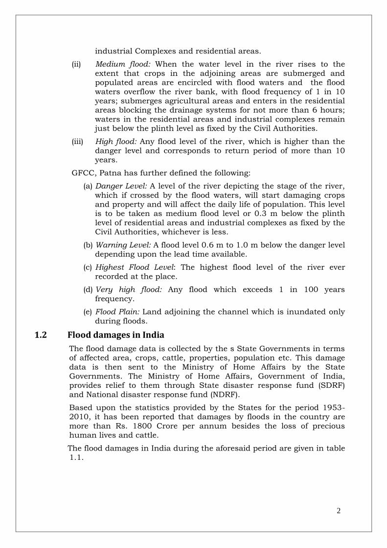
(ii) Medium flood: When the water level in the river rises to the
extent that crops in the adjoining areas are submerged and populated areas are encircled with flood waters and the flood
waters overflow the river bank, with flood frequency of 1 in 10 years; submerges agricultural areas and enters in the residential areas blocking the drainage systems for not more than 6 hours;
waters in the residential areas and industrial complexes remain just below the plinth level as fixed by the Civil Authorities.
(iii) High flood: Any flood level of the river, which is higher than the danger level and corresponds to return period of more than 10 years.
GFCC, Patna has further defined the following:
(a) Danger Level: A level of the river depicting the stage of the river,
which if crossed by the flood waters, will start damaging crops and property and will affect the daily life of population. This level is to be taken as medium flood level or 0.3 m below the plinth
level of residential areas and industrial complexes as fixed by the Civil Authorities, whichever is less.
(b) Warning Level: A flood level 0.6 m to 1.0 m below the danger level depending upon the lead time available.
(c) Highest Flood Level: The highest flood level of the river ever
recorded at the place.
(d) Very high flood: Any flood which exceeds 1 in 100 years
frequency.
(e) Flood Plain: Land adjoining the channel which is inundated only
during floods.
1.2 Flood damages in India
The flood damage data is collected by the s State Governments in terms of affected area, crops, cattle, properties, population etc. This damage
data is then sent to the Ministry of Home Affairs by the State Governments. The Ministry of Home Affairs, Government of India, provides relief to them through State disaster response fund (SDRF)
and National disaster response fund (NDRF).
Based upon the statistics provided by the States for the period 1953-2010, it has been reported that damages by floods in the country are
more than Rs. 1800 Crore per annum besides the loss of precious human lives and cattle.
The flood damages in India during the aforesaid period are given in table 1.1.

3
Table 1-1: Flood damages in India during 1953-2010.
# Item Unit Average
Annual
Damage
Maximum
Damage
Extent Year
1 Area affected M ha 7.06 17.50 1978
2 Population affected million 36.86 70.45 1978
3 Human lives lost nos. 1611 11316 1977
4 Cattle lost nos. 93202 618248 1979
5 Cropped area affected M ha. 3.46 10.15 1988
6 Damage to crops Rs crore 703 4247 2000
7 Houses damaged nos. 1193877 3507542 1978
8 Damage to houses Rs crore 276 1308 1995
9 Damage to public utilities Rs crore 828 5605 2001 Note: The damage data for 2003 onwards is under validation by States. The figures are without any
escalation and not at current price level. At the price level of 2010, the total flood damages have been estimated to Rs.8,12,500 crore considering escalation @ 10% per annum on compounded basis.
The devastating floods not only result in loss of precious human lives, cattle and damage to public and private property but also create a
sense of insecurity and fear in the minds of people living in the flood plains. The after-effects of floods like the agony of survivors, spread of epidemic, non-availability of essential commodities and medicines, loss
of the dwellings etc. make floods most feared among the natural disasters being faced by human kind.
Figure 1-2: River bank experiencing severe erosion

4
1.3 Flood prone areas in the country
Rashtriya Barh Ayog (RBA) had been set up in 1976 to assess the flood prone area in the country. As per the RBA Report -1980, it was
assessed that a total of 40 million ha area was flood prone in the country; by adding the maxima of flood affected area (34 million ha) in any year to the area protected (10 million ha) and deducting 4 million
ha of the protected area included in the flood affected area due to failure of protection works.
The XI Plan Working Group on Water Resources compiled the area
liable to floods as 45.64 million ha. Subsequently, XII Plan Working Group revised the assessment to 49.815 million ha as per the latest
database maintained by Central Water Commission on the flood damage data reported by the States for the period 1953-2010.
1.4 Flood Management Programme
As per Entry-17 of the Constitution of India, the flood control and
management works are planned and implemented by the respective States as per their own priority through own resources. This had resulted in increased flood damages due to non-completion of flood
control works and their poor maintenance on account of funds constraints. The Government of India therefore, decided to provide them financial assistance through various Plan schemes.
A plan scheme ”Flood Management Programme” for providing central assistance to the State Governments was taken up at an estimated cost
of Rs.8000.00 crore during XI Plan for river management, flood control, anti-erosion, drainage development, flood proofing, restoration of damaged flood management works and anti-sea erosion works; which
were considered critical in nature. This programme was appreciated by all the States and XII Plan Working Group on "Flood Management and
Region Specific Issues" recommended to continue with it in the XII plan period also.
1.4.1 Salient features of FMP
To avail the central assistance; the States have been advised to prepare the schemes of flood management works in an integrated manner covering the entire river/tributary or a major segment. However, in case of emergent situation arising due to high floods, the works in critical reaches are taken up immediately after flood season.
While submitting a proposal, the State Governments have to ensure acquisition of land required under the scheme and submit a certificate to this effect.
The State Governments have to ensure inclusion of the scheme in the State Plan and make requisite budget provision towards Central as well as State share on annual basis.
Subsequent installments of central assistance are released on receipt of the Utilization Certificate in FORM GFR-19A submitted by the concerned

5
Chief Engineer and the financial authority; and countersigned by the concerned Secretary of the implementing department/Finance Secretary of the State Government.
Actual expenditure incurred by the State Governments from their own resources in the financial year (in which the scheme is approved by the Empowered Committee under FMP) would be reimbursed in the same financial year or, if the central assistance is not released in that financial year, in the next financial year, in which case requirement of budget provision may not be necessary.
1.4.2 Funds released under FMP
A total of 406 no. flood management/anti-sea erosion works of various State Governments were included under the Programme out of which 218 works have been completed upto 31-03-2011 which have provided
protection to flood affected area of 1.87 million ha. These works have benefitted total population of 19.73 million in the concerned States.
1.5 Working Group on "Flood Management and Region Specific Issues"
The Working Group on "Flood Management and Region Specific issues" for XII Plan was constituted by the Planning Commission in Oct, 2010.
The Working Group has recommended strategies to deal with flood management during XII Plan ensuring development in the key areas in
order to achieve the broad objectives, targets, associated challenges and implementation of policies by the Centre and the States. In order to have effective programme for addressing the problem of flood in the
country, the following strategies are recommended to be effectively implemented during XII Plan.
Scientific assessment of flood prone area.
Integrated basin management approach.
Construction of dams and reservoirs with adequate flood cushion.
Development of detention basins.
Drainage improvement.
Strengthening of organizations.
Public-Private Partnership concept.
Inventory of works completed by State.
Provision for adequate funds for maintenance of existing works.
Procedural reforms.
Application of new technologies.
Emergency action plans.
1.6 Measures for flood management and erosion control
Different measures have been adopted to reduce the flood/erosion
losses and protect the flood plains. Depending upon manner in which they work, flood protection and flood management measures may be broadly classified as under.
1.6.1 Non-structural measures
The non-structural methods to mitigate the flood damages are as

6
under:
Flood Plain Zoning;
Flood Forecasting, Flood Warning and evacuation of the people;
Flood Proofing; and
Living with Floods.
1.6.2 Structural measures
The structural measures for flood management/erosion control (may further be classified into long term measures and short term measures)
which bring relief to the flood prone areas by managing the flood flows and thereby the flood levels are:
Creation of reservoir;
Diversion of a part of the peak flow to another river or basin where such diversion would not cause sizeable damages;
Construction of flood embankments;
Channel improvement;
Watershed management;
Construction of spurs, groynes, studs etc.;
Construction of bank revetment along with launching apron;
RCC porcupines in the form of screens, spurs, dampeners etc.; and
Vetivers, geo-cells, geo-bags etc.
The structural measures for flood management mentioned above are designed as per BIS codes. However, many works like RCC porcupines,
Geo-textile materials, vetivers etc are not covered in the existing BIS codes.
This handbook has been designed with a view to help all the practicing
engineers in the States and the Central Government for design, appraisal, construction and monitoring of the flood management works
covering all the relevant BIS codes, design manuals, guidelines, technical specifications for construction materials and practices etc. to meet new challenges in the flood management in India. This handbook
has been provided with typical examples of civil structures to help the field professionals in standardizing the design practices and use of state-of-art technology.
1.7 References
1. “Compendium of Guidelines in the field of Flood Management” prepared by GFCC.
2. Report of the Working Group on "Flood Management and Region
Specific issues" for XII Plan.
3. MoWR Guidelines of Flood Management Programme.

7
2.0 Construction Materials
2.1 General
Flood management and river training works in the form of
embankment, bank revetment, spurs, porcupines, sluices etc. are provided to manage/control the floods, to check the bank erosion and to improve drainage system. Construction of these works makes use of
different kind of materials depending on the nature of problem and the structure provided.
2.2 Type of construction materials
Different construction materials have their own uniqueness and are used according to the site conditions, availability, transportability, cost effectiveness, low maintenance cost etc.
Materials like boulders, timber are in use since ages, but due to their increased usage in other sectors leading towards reduced supply and
their environment un-friendly nature, use of them now-a-days is decreasing. High wear and tear of timber structures in underwater and near water situation makes it less suitable for their use in anti-
erosion measures.
Now–a-days, new innovative materials like Geo-textile in the form of Geo-textile bags, Geo-textile tubes, Sand filled Geo-mattress, Neo-web,
submerged vanes and RCC porcupines are being increasingly used in construction of revetments, spurs, groynes, embankments etc. These
materials are used due to their unique characteristics like durability, resistance to chemical waste, environment friendly nature, easiness in installation etc. Different construction materials being used for
structural measures for flood management are described below in detail.
2.2.1 River bed materials
Considering economy and ease in availability, river bed materials including sand and boulders are widely used in flood management
works. However, rounded river boulders are used in contained forms like gabions/crates but avoided in loose for pitching of the banks.
2.2.1.1 Soil
The soil is used as a fill material for flood embankments and spurs. The soil is also used for filling Geo-textile bags, mattress and tubes.
The soil shall preferably be coarse sand and free from organic material. Loamy and clayey type soil should be avoided

8
2.2.1.2 Boulders
Boulders are naturally available materials and are used as
construction material in various works, including slope protection for embankment, bank revetment, spurs etc. The boulder‟s shape, size, weight, gradation plays an important role in their effective use. The
boulders in a revetment should be well graded throughout the layer thickness. The boulders used should be angular and regular in shape.
The boulders should have sharp clean edges at the intersections of relatively flat faces. Rounded boulders should be avoided
2.2.2 GI wire mesh
Figure 2-1: A wire-mesh gabion
When appropriate size and quality
boulders are not available, gabions or crates filled with the boulders should be used. The gabions are rectangular boxes
made of hexagonal double twist steel wire mesh filled with the small size
boulders/cobbles. Crates are smaller in size than gabions. Opening of the gabions or crates should be smaller than
the size of smallest boulder/cobble so that they are kept intact.
2.2.3 Revet-mattress
Revet-mattress is rectangular mattress made with hexagonal double twisted steel wire mesh,
where the depth is small in proportion to its length and width. Revet mattress can be
differentiated with the gabions due to its lesser height. It is
divided into several cells by transverse diaphragms.
Figure 2-2: Hexagonal double twist
steel wire mesh, revet-mattress
2.2.4 Concrete blocks
Concrete is a composite material, made from the combination of
aggregate including sand, stones and a binder such as cement. Cement Concrete (CC) blocks are sometimes used in place of
boulders for construction of bank revetment or slope protection of the embankment. The CC blocks may be pre-casted or casted in-situ. The execution of works using the CC blocks is faster than the
boulder works.

9
2.2.5 Reinforced cement concrete porcupines
Figure 2-3: A sketch of typical RCC porcupine
Reinforced cement concrete (RCC) is mainly used for
construction of RCC porcupine screens due to
ease of construction,longer durability and low cost. Further details of RCC
porcupines are given in section 6. The use of RCC is replacing the timber in
construction of porcupine screens.
2.2.6 Geo-synthetics
A synthetic material in the form of strong flexible sheets either woven or non-woven, permeable, water tight membranes etc is used to improve soil quality and performance in different applications like
lining, drainage, filtration, separation, reinforcement and protection. For specific application in flood management works, products like
geo-textile bags/tubes, geo-membrane, geo-grid, geo-mattress are used. The generic name given to all these materials is referred as ”geo-synthetics”. As stipulated by Indian Road Congress (IRC:SP 59)
publications major important products of geosynthetic are been described in brief along with their application.
The geo-synthetics have different applications and perform different
functions, as described below in Table 2-1 below:
Table 2-1: Identification of the usual primary function for each type of geo-
synthetic
Type of Geo-synthetic Separation Reinforcemen
t Filtration Drainage Containment
Geo-textile
Geo-grid
Geo-net
Geo-membrane
Geo-synthetic Clay
Liner
Geo-foam
Geo-cells
Geo-composite
Geo-textile tube & bag

10
2.2.6.1 Geo-textile
The basic raw material which is used in
geo-textile is polymer and the most widely used polymeres are polypropylene and polyester. Based
upon the manufacturing process, geo-textile is often categorized as woven or
non woven. Woven geo-textile are manufactured by weaving weft thread through warp thread. While non woven
geo-textile is produced from randomly distributed continuous or staple fibers which are bonded together chemically,
thermally or mechanically
2.2.6.2 Geo-membrane
Geo-membrane materials are relatively thin and impervious sheets of
polymeric material, used primarily for linings and covers of liquids- or solid-storage facilities. This includes all types of landfills, reservoirs,
canals, and other containment facilities. Thus the primary function is always containment as a liquid or moisture barrier or both. Geo-membrane are of different types as per density and texture. Use of geo-
membrane is rapidly increasing in areas of soil stabilization, landfills, lagoons, lining, pavement, dams and spillways etc. These membranes
can be classified into HDPE (high density polyethylene) and LDPE (Low density polyethylene).
2.2.6.3 Geo-grid
A geo-grid is deformed/ non deformed grid like polymeric material formed by intersecting
ribs joined at junctions. Main function of a geo-grid is reinforcement by friction
mechanism. Geo-grids are:
(a) Either stretched in one or two directions for improved physical properties
(b) Made on weaving or knitting machinery by standard textile manufacturing methods
(c) By bonding rods or straps together
2.2.6.4 Geo-net Geo-nets are formed by a continuous
extrusion of parallel sets of polymeric ribs at acute angles to one another.
When the ribs are opened, relatively large apertures are formed into a net-like configuration.

11
2.2.6.5 Geo-synthetic Clay Liner
A geo-synthetic clay liner acts as a
hydraulic barrier. It consists of bentonite clay or other very low permeability material, supported by
geo-textile and/or geo-membrane which are held together by needling
or stitching. Main area of application is in landfills, rockfill dams etc.
2.2.6.6 Geo-composite
A geo-composite consists of a
combination of geo-textile, geo-grids, geo-nets and/or geo-membrane with numerous application areas. The
major functions encompass the entire range of functions listed for geo-synthetic discussed previously:
separation, reinforcement, filtration, drainage, and containment.
2.2.6.7 Geo-textile tube and bags
Geo-textile tube is a tube made of geo-textile and is generally filled with sand or dredged material. These tubes are generally about 1 m to 3 m
in diameter, though they can be customised to any size depending on their application. Today, geo-textile tubes ranging in diameters from
1.5 m to 5.0 m are used in many coastal and flood protection applications. Geo-textile bags are made of woven or non woven geo-textile fabrics which are specially designed for good soil tightness and
high seam efficiency. Geo-textile bags range in volume from 0.05 m3 to around 5 m3, and are pillow shaped, box shaped or mattress shaped
depending on the required application. Geo-textile bags have also been used as revetment, breakwaters, etc to build erosion protection measures. A sample of a geo-textile tube and bag is shown in the
Figure 2-4 and Figure 2-5.
Figure 2-4: Geo-textile bag Figure 2-5: Geo-textile tube

12
2.2.6.8 Erosion control mat
Figure 2-6: Erosion control mat
Erosion control mats can be of bio-
degradable or non degradable type. Erosion control mat provides immediate erosion control and high moisture
content to establish vegetation. It creates hospitable conditions for
invasion and establishment of plants.
Biodegradable mats are made of coir or straw fibers which are used for short
term erosion control unit growth of vegetation Biodegradable mats are made of coir or straw fibers which are used for
short term erosion control unit growth of vegetation.
While synthetic mats consist of UV stabilized non-degradable polypropylene fibers that are heat bonded at the contact points to provide a dimensionally stable matrix for soil erosion protection. For
very high embankments and embankments with steeper slopes, synthetic mat can be reinforced with galvanized mesh with or without
PVC coating. The composite nature of reinforced mat adds to the erosion control and sediment trapping function of the geo-synthetic matrix.
2.3 Technical specifications of construction materials and testing
Materials including gabions, revet-mattress, geo-textile tubes and bags
are used with specific strength and durability requirements as per the proposed structure. The detailed technical specifications of these
innovative materials along with the test methods and their recommended values for each parameter are being described in paras below in detail.
2.3.1 Wire mesh gabions
This work may consist of furnishing, assembling, and filling mechanically woven double twist wire mesh gabions with boulders.
These specifications are mainly in accordance with International Standards EN 10223, EN 10244
2.3.1.1 Material /structural properties
Desired properties for various components for fabrication of wire mesh gabions are as under
2.3.1.1.1 Wire
All tests on the wire mesh, lacing wire should be performed prior to
manufacturing the mesh.
Tensile strength: Both the wire used for the manufacture of gabions
and the lacing, shall have a tensile strength of 350-500 N/mm2, in

13
accordance with EN 10223-3.
Elongation: Elongation shall not be less than 10%, in accordance with
EN 10223-3.The length of the sample should be more than 25 cm for conducting this test
2.3.1.1.2 Zinc coating
Minimum quantities of zinc should meet the requirements of EN 10244-2. The adhesion of the zinc coating to the wire shall be such that, when the wire is wrapped six turns around a mandrel having
four times the diameter of the wire, it does not flake or crack when rubbing it with the bare fingers, in accordance with EN 10244. The
mesh wire shall show no rusty spots on any part of the surface excluding the cut ends. Minimum quantity of zinc (gm/sqm) based on the internal diameters of 2.2 mm, 2.7 mm & 3.4 mm should be 230,
245 and 265 respectively
2.3.1.1.3 PVC coating
The initial properties of PVC coating material shall have a
demonstrated ability to conform to the following requirements. The Specific Gravity should be in the range from 1.30 kg/dm3 to 1.35 kg/dm3, when tested in accordance with Test method ISO 1183. Tensile Strength should not less than 20.6 Mpa, when tested in accordance with test method ISO 527. Elongation at break should not
be less than 200% in accordance with ISO 527. The PVC coating shall not show cracks or breaks after the wires are twisted in the fabrication of the mesh.
Wherever, there is high changes of corrosion, alternate wetting and drying, high salinity, presence of shingles in water etc a further refinement in coating shall be used like Galmac (where Zinc + 10%
Aluminum) coating to the main steel wire mesh. Further, if there is more severe condition, an additional coating of PVC coating shall be
applied
2.3.1.1.4 Mesh characteristics
Mesh wire: Diameter – Inner diameter shall be 2.7 mm for the Zinc
coated wire and when measured with PVC coating the outer diameter shall be 3.7 mm.
Selvedge wire: Diameter – Inner diameter shall be 3.4 mm for the Zinc
coated wire and when measured with PVC coating the outer diameter shall be 4.4 mm.
Mesh opening: Nominal Dimension D =100 mm.
Lacing and stiffener wire: Diameter – Inner diameter shall be 2.2 mm for the Zinc coated wire and when measured with PVC coating the
outer diameter shall be 3.2 mm

14
2.3.1.1.5 Boulders
The boulders for gabions shall be hard, angular to round, durable and of such quality that they shall not disintegrate on exposure to
water or weathering during the life of the structure. The size may be between 0.15 m and 0.25 m. The range in sizes shall allow for a
variation of 5% oversize and/or 5% undersize rock, provided it is not placed on the gabion exposed surface. The size shall be such that a minimum of three layers of boulders must be achieved when filling
the gabions of 1m thick
2.3.1.2 Tolerances
Wire: Wire tolerances based on the internal diameters of 2.2 mm, 2.7
mm & 3.4 mm should be ± 0.06 mm, ± 0.06 mm and ± 0.07 mm respectively in accordance with EN 10218-2.
Mesh opening: Tolerances on the hexagonal, double twisted wire mesh, opening shall not exceed -4% to 16% on the nominal dimension value.
Gabions: 5 % (±) on the length, width, and height
2.3.1.3 Tests for the gabions
Different tests to be carried on the gabion material are tabulated along with references and standards in Table 2-2.
Table 2-2: Tests for the gabions
Mesh Type 10' x 12' References of Specifications
Mesh Opening “D” mm 100 EN10223
Mesh Tolerance +16% to –4% EN10223
Unit Dimensions
Tolerances in sizes of
units ± 5% ASTM A975
Mesh Wire Diameter (mm)
2.7/3.7 (Inner Dia/Outer Dia) EN10223
Tolerance (±) mm 0.08 BS1052
Zn Coating Min (gsm) 240 ASTM A 641
Selvedge/Edge Wire
Diameter (mm) 3.4/4.4 (Inner Dia/Outer Dia) EN10223
Tolerance (±) mm 0.10 BS1052
Zn Coating
(Selvedge/Edge Wire)
Min (gsm)
260 ASTM A 641
Lacing Wire Diameter
(mm) 2.2/3.2 (Inner Dia/Outer Dia)
Tolerance (±) mm 0.06 BS1052
Zn Coating (Lacing Wire) Min (gsm)
220 ASTM A 641
Fasteners (mm) 3.0/4.0 (Inner Dia/Outer Dia)
Stiffeners (mm) 2.2/3.2 (Inner Dia/Outer Dia)
Zn coating on fastener/
stiffener (gsm) 240 ASTM A 641
PVC Coating
Colour Grey-RAL 7037 ASTM D 1482
Thickness Nominal (mm) 0.50 ASTM A 975

15
Thickness Minimum (mm)
0.38 ASTM A 975
Specific Gravity 1.30 – 1.35 ASTM D 792
Tensile strength Not less than 20.6 MPa ASTM D 412
Modulus of Elasticity Not less than 18.6 MPa ASTM D 412
Hardness Between 50 and 60 Shore D ASTM D 2240
Brittleness temperature Not higher than –90C ASTM D 746
Weight loss Less than 5% after 24 hour at
1050 C ASTM D 2287
Abrasion Resistance The percentage of weight loss
shall be less than 12% ASTM D 1242
Salt spray Exposure and
Ultraviolet Light
exposure
a) The PVC shall show no effect
after 3000 hours of salt spray exposure
b) The PVC shall show no effect of
exposure to ultraviolet light with
test exposure of 3000 hours
using apparatus Type E at 630C c) After the salt spray test and
exposure to ultraviolet light, the
PVC coating shall not show
cracks or noticeable change of
colour, or blisters or splits. In addition, the specific gravity,
tensile strength, hardness and
resistance to abrasion shall not
change more than 6%, 25%, 10%
and 10% respectively from their
initial values.
ASTM B 117
ASTM D 1499
and G 23
2.3.2 Geo-textile as filter The material should be woven with multifilament yarn in both warp and weft direction or non-woven needle punched type with
continuous filament. The geo-textile shall be preferably made of polypropylene. The material may have about 70% polypropylene and rest may be polyethylene or any other equivalent material. The
standard roll length and width should be 100 m and 5 m. The average roll values of geo-textile should be as shown in Error! Reference source not
ound.. Table 2-3: Properties of geo-textile as filter
# Properties Marginal Value
Reference for Test Method
Mechanical Properties
1 Tensile strength (Warp/Weft)(=>) 28/26 KN/m IS 1969
2 Elongation at designated peak tensile load
(Warp/Weft)(<=)
25%/25% IS 1969
3 Trapezoid tear strength Warp/Weft) (=>) 300 N/300N ASTM D 4533
4 Puncture Strength(=>) 250 N ASTM D 4833
Hydraulic properties
1 Apparent opening size(<=) 75 microns ASTM D 4751
2 Permeability(=>) 10 l/m2/s ASTM D 4491
Physical
Unit Weight(=>) 140g/sqm ASTM D 3776

16
2.3.3 Geo-textile bags.
Geo-textile bags are made of woven/non-woven polypropylene/polyester geo-textile. Double layer geo-textile bags
using woven and non-woven geo-textile are used for harsh conditions. Geo-textile used to manufacture geo-textile bags should have high mechanical properties for enhanced durability along with enhanced
puncture, abrasion and U.V. resistance characteristics. Geo-textile should be inert to biological degradation and resistant to naturally
encountered chemicals, alkalis, and acids.
Geo-textile used to manufacture geo-textile bags made of non-woven material may conform to the properties listed in Table 2-4.
Table 2-4: Properties of non-woven geo-textile bag
Properties Reference for Test Method
Unit Values
Properties of Geo-textile
Polymer Type Polyester/PP
Nominal Mass ISO 9864 Gms/Sq.
m
≥400
Tensile Strength ASTM D4595 kN/m ≥20
Tensile Elongation ASTM D4595 % ≥40% & ≤ 90%
Puncture Resistance ASTM D4833 kN ≥ .40
Opening Size ASTM D 4751 mm ≥0.07mm & ≤0.16mm
UV resistance ASTM D 435 %/Hr 70/50
Properties of Geo-textile Bag
Seam Type Double Seam
Preferably flat dimensions
103 cm x 70 cm
Geo-textile used to manufacture geo-textile bags having double layers both for woven and non-woven material should conform to the properties listed in Table 2-5.
Table 2-5: Properties of double layer geo-textile bag
Properties Reference for Test Method
Unit Values
Non Woven
Woven
Properties of Geo-textile
Polymer Type PP PP
Weight ISO 9864/ ASTM
D5261 Gms/Sqm ≥300 ≥230
Tensile Strength ASTM D 4595 kN/m ≥12 ≥35
Tensile Elongation ASTM D 4595 % ≥30% &
≤90% ≥05% & ≤30%
Tensile Strength ASTM D4632 kN ≥0.80 ≥1.5
Grab Elongation ASTM D4632 % ≥30% &
≤90 ≥05% & ≤3 %
Puncture Resistance ASTM D4833 kN ≥ .40
Opening Size ASTM D4751 mm ≥0.06 & ≤0.17
≥0.10 & ≤0.25
UV Resistance ASTM D4355 %/hrs 70/500 70/ 00
Properties of Geo-textile Bag
Seam Type Double Seam
Preferably flat
dimensions 2.00m x 1.50m

17
Note: Lay Flat dimensions of the Geo-textile Bags given in the table above are preferable sizes. The Client is free to use site specific sizes lesser than specified values but shall not exceed the dimensions given in the table
2.3.4 Geo-textile tubes
Geo-textile tubes should be made of high-tenacity polypropylene yarns
which are woven into a stable network such that the yarns retain their relative position. These geo-textile tubes are often filled hydraulically
with slurry of sand and water, although many other fill materials may also be used. Each fill port may consist of a Geotextile sleeve having a length of at least 1.5 m and a circumference slightly greater than that
of the filling pipe. Sometimes double layer of sheets of woven textiles may also be required in consideration of added UV protection for a
prolonged life and sufficient abrasion resistance. The geo-textile tubes should be constructed to meet the dimensions, type of materials and properties mentioned in Table 2-6, table 2-6 and table 2-7
respectively.
Table 2-6: Dimensions for Geotextile tube
Property/Parameter Units Values
Geotextile tube length M 20
Geotextile tube diameter M 3
Filling port length M 2
Filling port diameter M 0.5
Filling port spacing M 5
Seam strength efficiency(=>) % 40
Table 2-7 contains type and structure of material to be used for geo-
textile tubes.
Table 2-7: Type of fabric for geo-textile tube
Property Reference for Test Method
Units Values
Polymer n/a n/a Poly propylene
Roll dimensions (LxW) n/a n/a 100mx5m
Structure
n/a n/a
Woven with multifilament
yarn in both warp and weft
directions
Weight per unit area ASTM D 3776 Gm/m2 >=330
Properties of geo-textile tubes are given in and
Table 2-8 contains properties of geo-textile tubes.
Table 2-8: Properties for geo-textile tube
# Properties Marginal Value Reference for Test Method
Mechanical Properties
1 Tensile strength (Warp/Weft)(=>) 80/78 KN/m IS 1969
2 Elongation at designated peak tensile load (Warp/Weft)(<=)
25%/25% IS 1969
3 Trapezoid tear strength Warp/Weft) (=>) 1600 N/1600N ASTM D 4533
4 Puncture Strength(=>) 600 N ASTM D 4833
Hydraulic properties
1 Apparent opening size(<=) 250 microns ASTM D 4751
2 Permeability(=>) 18 l/m2/s ASTM D 4491

18
2.3.5 Vetiver for bank protection
The vetiver is a special type of grass having longer roots of length. This grass is infertile in nature. Due to their long roots and high tensile
strength this grass is resistant to the high velocity streams and checks the erosion Desirable properties of the vetivers are given in Table 2-9.
Table 2-9: Properties of vetivers for bank protection
# Properties Mar Value
1 Average tensile strength 75 MPa
2 Root length Up to 3 m
3 Life under 14 m of water Up to 5 months
4 Air temperature range for sustainability -140C to 550C
5 Soil Ph 3 to 10
2.4 References
1. Design practices and specifications adopted by the Maccafferi India Pvt
Ltd.
2. Draft for 2nd revision of IS code 8408.

19
3.0 Design of Flood Embankment
3.1 General.
A levee or dyke may be defined as an earthen embankment extending
generally parallel to the river channel and designed to protect the area behind it from overflow of flood waters.
Embankments are the oldest known forms of flood protection works and have been used extensively for this purpose. These serve to prevent inundation, when the stream spills over its natural section, and
safeguard lands, villages and other properties against damages
3.2 Planning of embankments.
Basic understanding and steps to be taken up for planning of flood embankments has been described in the paras below
3.2.1 Classification
Embankment Manual, CW&PC, 1960 stipulates that an embankment is designated as low, medium or major (according to its height above natural surface level (NSL). The details are as under in Table 3-1.
Table 3-1: Classification of embankment
# Classification of
embankment
Criterion
1 Low Embankment Height < 10 ft (3 m)
2 Medium Embankment 10 ft (3 m) <Height> 30 ft
(9 m)
3 Major Embankment Height > 30 ft (9 m)
A typical high embankment with slope protection is shown in Figure
3-1.
Figure 3-1:Typical high embankment with slope protection using geo-mattress

20
3.2.2 Requirement of data.
BIS code 12094: 2000 stipulates that the following data is required for planning of an embankment
3.2.2.1 Topographical data.
Index plan showing area affected, contour survey plan of the area, past river courses, plan and section of earlier executed works
3.2.2.2 Hydrological data.
Discharge, gauge, velocity, carrying capacity, extent of spill of river, cross sections and longitudinal section of river, rainfall data for the basin sediment flow and river behavior like aggrading or degrading etc
3.2.2.3 History of past floods.
Indicating duration of floods, flood discharges and corresponding levels, stage of river at which damage was most pronounced, extent of damage
etc.
Generally the data as mentioned above is not available while framing
the detailed project report. The efforts should be made to collect the above mentioned data specially gauge and discharge data for past recent 10-20 years for the river from all possible sources
3.2.3 Degree of protection.
BIS code 12094: 2000 stipulates that the height of embankment and the corresponding cost and Benefit Cost Ratio should be worked out for various flood frequencies taking into account the damages likely to
occur. The degree of protection which gives the optimum Benefit Cost Ratio should be adopted.
Benefit Cost Ratio of the flood management/coastal protection scheme should be higher than 1. The B. C. Ratio is calculated dividing the annual benefits of the scheme by annual cost of the scheme. The annual benefits should be based on losses occurred during last 10 years duly verified by the Competent Authority. Annual cost of the scheme is taken as 16% of capital cost of scheme envisaging construction of embankments. Annual cost is adopted as 17% of capital cost of scheme envisaging construction of anti erosion measures
However till such time as the details of all the relevant parameters are available, following criterion for degree of protection may be adopted
3.2.3.1 Embankment for predominantly agricultural areas.
The design flood for this type of embankment is kept 25 years for fixation of crest level
3.2.3.2 Embankments for township or areas having industrial installations
The design flood for this type of embankment is kept 100 years for fixation of crest level.
In the cases where anti erosion measures are proposed along with the
embankment then design flood may be kept as 50 years for rural areas

21
and 100 years for urban/industrial areas. In certain special cases, where damage potential justifies, maximum observed flood may also be
considered for fixing the crest level.
In cases where gauge & discharge sites are not present, discharge may
be worked out using the Empirical formula using the catchment area, extent of rainfall, catchment characteristics etc. Further hydrological data may be adopted using the regional hydrological booklets/manuals,
prepared by the Hydrological Studies Organization, CWC. A typical earthen embankment is shown in Figure 3-2.
Figure 3-2: A typical earthen embankment
3.2.4 Alignment & spacing of embankment.
BIS code 12094: 2000 stipulates following guidelines related with the alignment and spacing of the embankment
3.2.4.1 Alignment.
The embankments should be aligned on the natural bank of the river, where land is high and soil available for the construction of
embankments. The alignment should be such that important township, vital installations, properties, cropped area is well protected by the embankment The alignment should be such that high velocity flow is
quite distant from the toe of embankment to avoid scouring of the same and if embankments‟ alignment is near the high velocity flow then slope
and toe protection in the form of pitching along with launching apron using the boulders, geo-bags, sand filled geo-mattress may be given. RCC porcupine screens along the toe line may also be used to retard the
flow to induce siltation and check scouring of the toe-line. Alignment should also be planned so that land acquisition is feasible and not prolonged
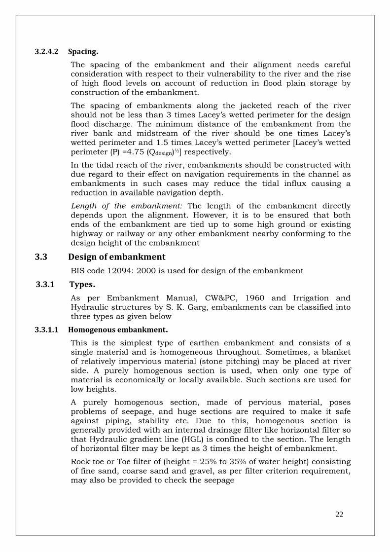
22
3.2.4.2 Spacing.
The spacing of the embankment and their alignment needs careful consideration with respect to their vulnerability to the river and the rise
of high flood levels on account of reduction in flood plain storage by construction of the embankment.
The spacing of embankments along the jacketed reach of the river should not be less than 3 times Lacey‟s wetted perimeter for the design flood discharge. The minimum distance of the embankment from the
river bank and midstream of the river should be one times Lacey‟s wetted perimeter and 1.5 times Lacey‟s wetted perimeter [Lacey‟s wetted
perimeter (P) =4.75 (Qdesign)½] respectively.
In the tidal reach of the river, embankments should be constructed with due regard to their effect on navigation requirements in the channel as
embankments in such cases may reduce the tidal influx causing a reduction in available navigation depth.
Length of the embankment: The length of the embankment directly
depends upon the alignment. However, it is to be ensured that both ends of the embankment are tied up to some high ground or existing
highway or railway or any other embankment nearby conforming to the design height of the embankment
3.3 Design of embankment
BIS code 12094: 2000 is used for design of the embankment
3.3.1 Types.
As per Embankment Manual, CW&PC, 1960 and Irrigation and Hydraulic structures by S. K. Garg, embankments can be classified into three types as given below
3.3.1.1 Homogenous embankment.
This is the simplest type of earthen embankment and consists of a single material and is homogeneous throughout. Sometimes, a blanket
of relatively impervious material (stone pitching) may be placed at river side. A purely homogenous section is used, when only one type of material is economically or locally available. Such sections are used for
low heights.
A purely homogenous section, made of pervious material, poses
problems of seepage, and huge sections are required to make it safe against piping, stability etc. Due to this, homogenous section is generally provided with an internal drainage filter like horizontal filter so
that Hydraulic gradient line (HGL) is confined to the section. The length of horizontal filter may be kept as 3 times the height of embankment.
Rock toe or Toe filter of (height = 25% to 35% of water height) consisting
of fine sand, coarse sand and gravel, as per filter criterion requirement, may also be provided to check the seepage

23
3.3.1.2 Zoned embankment
It consists of an inner core or section which is impervious and which
checks the HGL. The transition zone prevents piping through cracks which may be developed in the core due to shrinkage and swelling of core material. The outer zone gives stability to the central impervious
core and also distributes the load over a larger area of foundations.
The core of the embankment may be constructed using the clay mixed
with the fine sand or fine gravel. Pure clay is not best material for core as it shrinks and swells too much. Silt or silty-clay may also be used as core.
Sand filled geo-tube, which is a relatively impervious material, may also be used as core of the embankment. Typical zoned embankment is shown in Figure 3-3.
Figure 3-3: Embankment with core
3.3.1.3 Diaphragm type embankment.
Diaphragm type embankment has a thin impervious core, which is
surrounded by sand. The impervious core, called as diaphragm, is made of imperious soils, concrete, steel, timber or any other material. It acts as water barrier to prevent seepage. The diaphragm must be tied to the
bed rock or to a very impervious foundation material.
The diaphragm type of embankment is differentiated from zoned
embankment, depending upon thickness of core. If thickness of diaphragm is less than 10 m or less than height of embankment, the embankment is to be considered as diaphragm type embankment. Sand
filled geo-tube may also be used as core or diaphragm of the embankment
3.3.2 Design HFL.
The essential requirements for the design of embankment are the
determination of design High Flood Level (HFL), hydraulic gradient, free board, side slopes, top width etc.
The design HFL should be obtained from gauge discharge relationship (G-D curve). The design HFL so obtained should be verified on the basis of observed cross-sections, slopes and velocities of the river in recent
years. The design HFL may also be obtained from flood frequency analysis for corresponding return period.
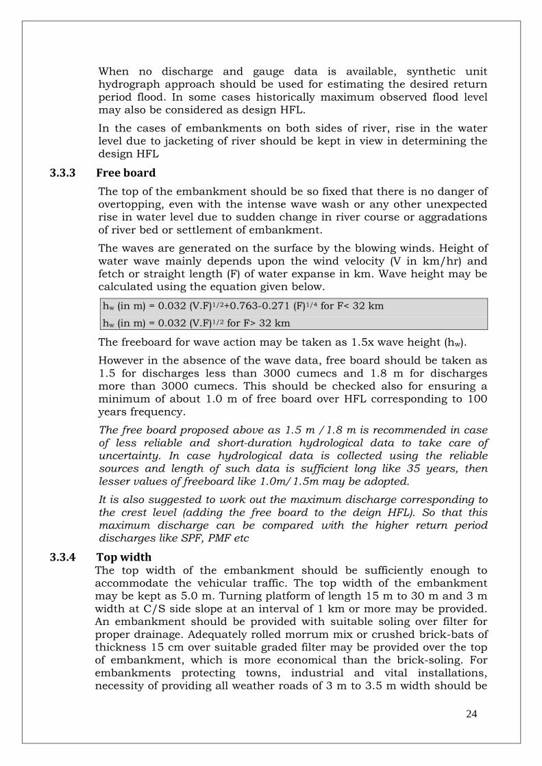
24
When no discharge and gauge data is available, synthetic unit hydrograph approach should be used for estimating the desired return
period flood. In some cases historically maximum observed flood level may also be considered as design HFL.
In the cases of embankments on both sides of river, rise in the water level due to jacketing of river should be kept in view in determining the design HFL
3.3.3 Free board
The top of the embankment should be so fixed that there is no danger of overtopping, even with the intense wave wash or any other unexpected rise in water level due to sudden change in river course or aggradations
of river bed or settlement of embankment.
The waves are generated on the surface by the blowing winds. Height of
water wave mainly depends upon the wind velocity (V in km/hr) and fetch or straight length (F) of water expanse in km. Wave height may be calculated using the equation given below.
hw (in m) = 0.032 (V.F)1/2+0.763-0.271 (F)1/4 for F< 32 km
hw (in m) = 0.032 (V.F)1/2 for F> 32 km
The freeboard for wave action may be taken as 1.5x wave height (hw).
However in the absence of the wave data, free board should be taken as
1.5 for discharges less than 3000 cumecs and 1.8 m for discharges more than 3000 cumecs. This should be checked also for ensuring a minimum of about 1.0 m of free board over HFL corresponding to 100
years frequency.
The free board proposed above as 1.5 m /1.8 m is recommended in case of less reliable and short-duration hydrological data to take care of uncertainty. In case hydrological data is collected using the reliable sources and length of such data is sufficient long like 35 years, then lesser values of freeboard like 1.0m/1.5m may be adopted.
It is also suggested to work out the maximum discharge corresponding to the crest level (adding the free board to the deign HFL). So that this maximum discharge can be compared with the higher return period discharges like SPF, PMF etc
3.3.4 Top width
The top width of the embankment should be sufficiently enough to accommodate the vehicular traffic. The top width of the embankment may be kept as 5.0 m. Turning platform of length 15 m to 30 m and 3 m
width at C/S side slope at an interval of 1 km or more may be provided. An embankment should be provided with suitable soling over filter for
proper drainage. Adequately rolled morrum mix or crushed brick-bats of thickness 15 cm over suitable graded filter may be provided over the top of embankment, which is more economical than the brick-soling. For
embankments protecting towns, industrial and vital installations, necessity of providing all weather roads of 3 m to 3.5 m width should be
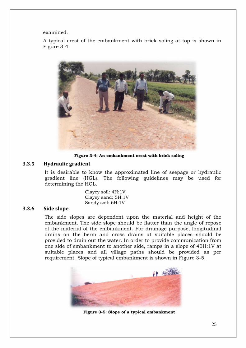
25
examined.
A typical crest of the embankment with brick soling at top is shown in
Figure 3-4.
Figure 3-4: An embankment crest with brick soling
3.3.5 Hydraulic gradient
It is desirable to know the approximated line of seepage or hydraulic
gradient line (HGL). The following guidelines may be used for determining the HGL.
Clayey soil: 4H:1V Clayey sand: 5H:1V Sandy soil: 6H:1V
3.3.6 Side slope
The side slopes are dependent upon the material and height of the
embankment. The side slope should be flatter than the angle of repose of the material of the embankment. For drainage purpose, longitudinal drains on the berm and cross drains at suitable places should be
provided to drain out the water. In order to provide communication from one side of embankment to another side, ramps in a slope of 40H:1V at
suitable places and all village paths should be provided as per requirement. Slope of typical embankment is shown in Figure 3-5.
Figure 3-5: Slope of a typical embankment

26
3.3.6.1 River side slope
The river side (R/S) slope should be flatter than the under-water angle
of repose of the material. Up to an height of 4.5 m, the slope should not be steeper than 2H:1V and in case of high embankments, slope should not be steeper than 3H:1V, when the soil is good and to be used in the
most favorable condition of saturation and drawdown.
(a) In case of higher embankment protected by rip-rap/pitching, the slope of
embankment up to 6 m high may be 2H:1V or 2.5H:1V depending upon the
type of slope protection.
(b) If the construction material is sandy, the slope should be protected with a
cover of 0.6 m thick good soil; and
(c) It is usually preferable to have more or less free draining material on the
river side to take care of sudden drawdown. In case of high and important
embankment, slopes may be protected by the stone pitching, concrete
blocks with open joints or sand filled geo-mattress to protected against
sudden drawdown or erosive action of river flow.
(d) For embankment with height more than 6 m, line of saturation should be
found by Kozeny‟s base parabola method and stability analysis should be
carried by slip circle method for finalizing river side slope (IS 7894)
3.3.6.2 Country side slope
A minimum cover of 0.6 m over the HGL should be maintained. For embankment up to height of 4.5 m, the country side slope should be
2H:1V from the top up to the point where the cover over HGL is 0.6 m after which a berm of suitable width, with country side slope of 2H:1V
from the end of the berm up to the ground level should be provided.
For embankment of height from 4.5 m to 6.0 m, the country side slope should be 3H:1V from the top up to the point where the cover over HGL
is 0.6 m after which a berm of suitable width, with country side slope of 3H:1V from the end of the berm up to the ground level should be provided.
For embankment of height more than 6 m, detailed design should be done. Typical cross section of an earthen embankment is shown as
under as Figure 3-6.
Figure 3-6: Typical cross-section of an embankment

27
3.3.6.3 Borrow Pits.
As per BIS code 11532, for taking out soil for use in embankment, borrow pit should be preferred on the river side and located at minimum
distance of 25 m from the toe of embankment. In order to obviate development of flow parallel to embankment, cross-bars of width 8 times
the depth of borrow pits @ 50-60 m c/c shall be left in the borrow pits. When adding new earthwork to existing embankment, the old bank shall first be cut and benched into steps with treads sloping slightly
towards centre of the embankment. Surface of old work should be properly wetted so that new earth may adhere to old
3.3.7 Drainage
For drainage, longitudinal drains should be provided on the berm and cross drains at suitable places should be provided to drain the water from the longitudinal drains. Toe drain should be provided to prevent
sloughing of toe. Perforated pipe embedded in properly designed graded filter with arrangements for disposal of water in the country side should be provided. Use of geo-textile material is also useful for safe drainage.
Provision of drainage pipe and geo-textile material in embankment is shown in Figure 3-7 and Figure 3-8.
Figure 3-7: Provision of drain pipe

28
Figure 3-8: Provision of geo-textile material
3.3.8 Safety measures in design
Structure should be stable under all stages of construction and conditions of saturation and drawdown. It is therefore necessary that
stability checks for various conditions should be done to ensure safety. Seismic forces should also be considered for high embankments. The
factor of safety should be higher than 1.3.
Safety against cracks due to unequal settlement and wetting:
Unequal settlements can be largely avoided by preparing the
foundations properly and by selecting suitable material for construction. Where the foundation soil is weak, suitable strengthening measures
may be taken. Clayey soils containing organic matter such as remains of plants and root should be rejected. Well graded homogenous materials are most suitable for construction. In case of difficulty in getting full
quantities of same material, zonal sections with impervious core and a pervious casing may be adopted. In high embankments it is desirable to mechanically compact the earth fill in suitable layers with a view to
achieve optimum density with appropriate moisture content. Breaking of big clods especially in clayey soils is to be done ad organic/vegetable
matter separated to safeguard against seepage/leakage/piping.
3.3.9 Sluices
Sluices with regulating arrangements should be provided for country side drainage. The size of sluice will depend upon the intensity of
rainfall and the catchment area to be drained. Sluices may be designed as per provision of BIS code IS 8835:1978.
3.3.10 Causes of failure of embankment
As stipulated by the CBIP publication - 1989 River Behavior Management and Training Volume-I, in the absence of proper maintenance and supervision, embankments are susceptible to
breaches due to various causes given below.
(a) Improper compaction and settlement of embankment. (b) Transverse cracks due to unequal settlement. (c) Inadequate drainage and pore pressure development. (d) Erosion of riverside slope due to river current and wave wash.

29
(e) Caving-in of the banks. (f) Overtopping of flood water during high floods. (g) Failure of foundations due to infiltration; and (h) Piping as a result of insufficient cross-section. Leaks and cracks due to
shrinkage of soil, and rat holes. (i) Increase in moisture content of the soil material.
3.3.11 Preventive measures
As stipulated by the CBIP publication- 1989 River Behavior Management and Training Volume-I, breaches/failures can be avoided by adopting suitable preventive measures mentioned briefly underneath:
(a) Toe drainage. (b) Placing sands bags near toe (with drains covered by wooden planks) in
order to increase shear resistance actuating forces causing slip. (c) Reducing seepage by lowering seepage head by constructing ring wells
with sand bags near the toe. (d) Plugging piping holes with divers using tarpaulins soaked with bitumen
from river side face of the hole. (e) Raising height of embankment (in case of overtopping) by using wooden
planks without endangering stability against slip.
3.3.12 Closure of breach
Breaches should be closed on war footing so that the flooding of country
side can be minimized. Usually retired embankments are constructed around the breach connecting the retired embankment with the original one at points sufficiently away from the breach so that by the time
construction of retired embankment is over, the breach doesn‟t propagate to the connecting points. Vertical closure by driving piles all along the breach width is better than trying to close the breach
horizontally starting from ends, since here will be very high drag due to increasing velocity of the stream passing through the neck as the breach
width gets narrowed down
3.3.13 Protection of embankment
An embankment under direct attack of a river needs protection against failure. Different protective measures which are commonly employed to
protect embankment are as under.
(a) Revetment/mattressing to protect against erosive action of river. (b) Spurs/groynes to deflect/dampen high velocity attacking the embankment (c) Different grade control measures to tame a river flowing in steep terrain. (d) Improving shear strength of embankment soil by growing shallow rooted
vegetation.

30
A typical completed embankment is shown in Figure 3-9.
Figure 3-9: A typical completed embankment with road on crest
3.4 Stability analysis for high embankments
The criterion for stability analysis for high embankment is based on the
stability analysis of embankment dams.
The most important cause of failure of an embankment is sliding. A portion of the earth may slide downwards and outwards with respect to
remaining part, generally along a well defined slice surface. The failure is caused when the average shearing stress exceeds the average
shearing resistance along the sliding surface due to various loading conditions.
Slope stability is generally analyzed by two methods depending upon the
profile of failure surface viz. (a) Circular arc method and (b) Sliding Wedge method. In the „Circular arc‟ method or „Swedish Slip Circle‟
method, the rupture surface is assumed cylindrical or in the cross-section by an arc of a circle. The sliding wedge method assumes that the failure surface is approximated by a series of planes.
Generally for low embankments the sections designed on consideration of hydraulic gradient and cover are found to be quite suitable under all stages of construction, condition of saturation and draw down provided
the foundation conditions are satisfactory. For high embankments the section proposed should be checked for stability by Swedish Circle
method. The minimum factor of safety aimed at should be 1.3.
If the embankment is located in an area subjected to earthquakes, the forces developed by such movements should also be taken in to account
while checking the stability. The value up to 0.1g for vertical acceleration and 0.2g for horizontal acceleration depending upon its
distance from the epicenter may be assumed for the design purposes in areas subject to earthquake

31
3.4.1 Selection of design parameters
The embankment material shear strength is obtained by performing tri-axial tests of borrow area materials compacted to densities aimed at
during construction. The foundation material strength is obtained by tests with undisturbed samples from tri-axial shear testing. Testing in
each case shall be from zero to maximum normal stress expected in the embankment.
The design shear parameters for fill material is fixed at 75% availability
from an adequate number of samples, and for foundation soils minimum shear strength values along foundation obtained are adopted after rejecting extreme or freak values.
3.4.2 Analysis procedure
The procedure of arriving at driving and resisting forces involves assumption of a tentative cross-section of the embankment, a possible
circular failure surface, division of the slip circle mass into a number of slices, calculation of forces on each slice and summation of the forces. The factor of safety against sliding for assumed failure surface is
obtained by the equation:
FS = ∑S/∑V
= C + (N-U) tan/W sin Where: FS = Factor of safety S = Resisting or stabilizing Force T = Driving or actuating force
C = C1x (b/ Cos ) N = Force normal to the arc or slice U = Pore water pressure.
= Angle of shearing resistance W = Weight of the slice Α = Angle made by the radius of the failure surface with the vertical at the centre of slice. C1 = Unit cohesion, and b = Width of the slice
3.4.3 Stability computation
The slope stability analysis is carried out to get the minimum factor of safety for a tested section under different loading conditions for downstream and upstream slopes respectively. The computer
programmes used for static analysis are used for the computations
3.4.4 Final selection of embankment section
Based on the results of studies for slope stability by static and pseudo
static method, final section of the embankment may be selected. In this selection, great emphasis is put on the experience of the designer and the data of behavior of embankments constructed in almost identical
situations

32
3.4.5 Defensive design measures
The design details should also include defensive measures to enhance their performance. The measures may include:
Provision of adequate freeboard for settlement, slumping and fault movement.
Use of wide transition zones of materials not vulnerable to cracking.
Use of drains near critical zones and central portion of embankment.
Use of wide core zones.
Use of adequate well-graded filter zone upstream of core to serve as a crack stopper.
Controlled compaction of embankment zones.
Removal or treatment of foundation materials that are of low strength or density.
Widening of core at abutment interfaces.
Special treatment of foundations at faults including provision of transition embankment sections.
Stabilization of hill slopes susceptible to sliding around reservoir rim.
3.5 Merits and demerits of embankments
Merits and demerits of flood embankments have been listed out below:
3.5.1 Merits
Merits of embankment as method of river training works are as under:
Embankments are the main mean of preventing inundation during flood season.
The initial cost of construction of embankment is low, although when raised subsequently, they may become a bit expensive.
Construction is easy and presents no difficulty, as it can be done by utilizing local resources in unskilled labor and materials. Maintenance is equally simple and cheap.
They can be executed in parts, provided that‟s ends are properly protected
3.5.2 Demerits
Embankments cause rising of high flood levels.
Embankments are fragile works. Bore holes caused by small animals like crabs, rats and worms may result in piping. They must be supervised closely during floods and protected, as soon as they are in danger.
In the event of a breach, there is a sudden and considerable inflow of water which may cause damage in the country side and deposition of sand making the area infertile.
Embankments are susceptible to direct attack of the river flow which can erode and undermine them.
Low lying areas may become infested with water borne disease if proper drainage is not provided.
In the case of river carrying considerable amount of silt, then deposition of silt on the river bed causes rise in the water level which may be lead subsequent overtopping of the crest level of embankment

33
3.6 References 1. BIS code 12094:2000 2. BIS code11532:1995
3. Preliminary draft Guidelines for planning and design of river embankment (Levees) (Second revision of IS 12094) (Feb, 2011)
4. Embankment manual (1960)
5. Irrigation Engineering and Hydraulic structures-1995 - S. K. Garg 6. River Behavior Management and Training Volume-I (Central
Irrigation and Power (CBIP), 1989

34
4.0 Design of Bank Revetment
4.1 General
CBIP-manual “River Behavior Management and Training Volume-I -1989” stipulates that protection of banks is a part and parcel of river
training works because bank caving is one of the causes of deterioration of river conditions. River passing through populated/agricultural areas necessitates protection of adjacent lands and properties threatened by
the erosion. The protection of river bank from the threat of erosion comes under Anti Erosion works. The purpose of bank protection may be training of river, protection of adjacent land and properties,
protection of nearby hydraulic structures like embankments etc. Generally, bank protection works are auxiliary to river training works
and expensive. Because of the high costs involved, all available materials are used. The river bank consists of the upper (above the Lowest water level or LWL) and lower sections (Below the LWL). The
lower bank acts as the foundation for supporting the upper bank and, is, generally more susceptible to erosion. Recession of bank is caused by
the erosion of lower bank, particularly at toe. The recession is fast, especially when there is sandy substrata below.
The upper bank is the portion between LWL and High Flood level (HFL).
Action on this bank portion is most severe when the current impinges normal to the bank. During high stage of floods, erosion is also due to strong current along the bank. A typical bank protection work is shown
in Figure 4-1.
Figure 4-1: A typical bank protection work
4.2 Causes of bank failures
CBIP-manual “River Behavior Management and Training Volume-I -1989” stipulates following causes of bank failure as listed below.

35
(a) Washing away of the soil particles from the bank by strong current. (b) Undermining the toe of bank by eddies, current etc followed by collapse of
overhanging material deprived of support. (c) Sliding or Sloughing of slope when saturated with water by floods of long
duration. Saturation decreases the shear strength of soil. The stability is further reduced by the pressure of seepage flow.
(d) Piping in sub-layers due to movement of ground water towards the river, which carries away material with it.
Causes (a) and (b) of bank failures may be attributed to erosion. Failure under (c) is due to reduction in shear strength and under (d) results
from foundation failure. An eroded bank is shown in Figure 4-2.
Figure 4-2: A typical eroded river bank
4.3 Methods of bank protection:
CBIP-manual “River Behavior Management and Training Volume-I -1989” stipulates that bank protection works may be classified as direct
and indirect. Direct protection works includes work done on the bank itself such as providing vegetal cover, pavement, revetment, grading of slope etc. Indirect protection of slopes includes works constructed not
directly on the banks, but in front of them for reducing the erosive forces of the current, either by deflecting the current away from the
banks or by inducing silt deposition near the bank.
If the current is not strong, bank can be protected by a vegetal cover using the shrubs and willows. Sometimes a special vegetal cover like
vetiver (the long rooted grass having high tensile strength) can also be used for bank protection. In the case of strong current, banks may be protected by pitching using stone/boulders, concrete blocks, sand filled
geo-bags/geo-mattress. The bank pitching is provided along with the launching apron to prevent the scouring under the water and the
consequent fall of pitching.
In case of more steep slopes the banks can also be protected by retaining wall/guide walls to save the cost of cutting. This method is

36
also beneficial when there is very limited land viz in hilly terrains.
Bank protection using the RCC porcupine screens comes under both
type of method of protection viz. direct and indirect method. RCC porcupines are laid over the bank slopes and also protrude into the river
section to induce siltation near the bank. Some innovative methods of bank protection are as under
4.3.1 Vetivers
The vetiver is a special type of grass having longer roots of length up to
3 m. These roots have an average tensile strength of 75MPa. This type of grass is a perennial type of grass which can grow under extreme and wide type of conditions. This grass can live upto 5 months under 14 m
of water. Due to their long roots and high tensile strength this grass is resistant to the high velocity streams and checks the erosion. The river
bank before and after the implementation of vetiver is shown in Figure 4-3 and Figure 4-4.
Figure 4-3: Bank before the
vetiver implementation Figure 4-4: Bank after the
vetiver implementation
4.3.2 Submerged vanes
Submerged vanes are under-water permeable type bank protection
measures. These vanes are kept at an appropriate angle with the bank and at appropriate height with intention to induce optimum siltation near the bank. Orientation of submerged vanes should be decided after
the model study to get their desired results. A typical cross section of river after implementing the submerged vanes is shown in Figure 4-5:
bank profile after implementing the submerged vanes .

37
Figure 4-5: bank profile after implementing the submerged vanes
4.3.3 RCC kellener Jettys
RCC Kellner Jettys are monolithic RCC structures very similar to the RCC porcupines. RCC Kellner jettys are cast in-situ or pre-casted and
consists of 3 RCC members. They are lighter than the RCC porcupines and there is no risk of rusting of the nuts and bolts as compared to the
RCC porcupines. A typical picture of RCC kellener Jetty is given as Figure 4-6.
Figure 4-6: RCC kellenrr Jetty
4.3.4 Geo-cell
A geo-cell (or Cellular Confinement System) consists of a three
dimensional honey comb mattress that can be filled with granular soil/aggregate/sand or concrete. A sketch of a typical geo-cell is provided below.

38
Geo-cell is made of HDPE or non-woven geo-textile strips, which are welded together to form a honey comb structure. The cellular
confinement provides a solution for slope surface erosion protection, earth retention, load support etc.
The geo-cell is used because of its low maintenance, easiness in installation, low wastage and low handling cost. The geo-cell ensures the integrity of granular in-fill materials resulting in extended protected
bank life. The system confines the fill material within its strong and flexible geo-textile cell structure.
The 3D zone of confinement reduces the lateral movement of soil
particles which increase the shear strength of the confined soil and decrease the deformation. The cell height may be kept as 50mm for
HDPE and 100 mm for non woven geo-textile. The minimum sheet thickness of geo-cell may be 1.1 mm (ASTM D 5199) in case of HDPE.The infill material in geo-cell should be predominantly granular
with a maximum particle size of 50 mm. The fines fraction (<75 μm) should not be greater than 10%.
A typical geo-cell being prepared at the site is shown in Figure 4-7.
Figure 4-7: A typical geo-cell being prepared at site
4.4 Planning of bank revetment
IS code 14262:1995 mentioned following provisions regarding planning of bank revetment or pitching.
4.4.1.1 Requirement of data
Following data is required for planning of a bank revetment.
4.4.1.2 Topographical data

39
Index plan showing area affected, bank slope, type of soil, plan and section of earlier executed works
4.4.1.3 Hydrological data & other data
Discharge, gauge, velocity, bank to bank cross sections and longitudinal section of river, Gauge and discharge relationship, bed material grain
size etc
4.4.1.4 History of past erosion of banks during floods
Location of erosion prone sites, their extent, annual bank erosion lines
(preferably be obtained using satellite imageries) , maximum annual erosion, annual erosion rate, extent of damage etc.

40
4.4.2 Degree of protection
The design flood for pitching/revetment may be calculated for 50 years return period using the flood frequency analysis. In certain special
cases, where damage potential justifies, maximum observed flood may also be considered for fixing the crest level. The design HFL should be
obtained from gauge discharge relationship (G-D curve).
In cases where G&D site are not present, discharge may be worked out with the Empirical formula using the catchment area, extent of rainfall,
catchment characteristics etc. A typical bank pitching is shown in Figure 4-8.
Figure 4-8: A typical bank pitching in wire crates
4.5 Design of bank revetment
IS code 14262:1995 provides for following provisions regarding design of bank revetment
4.5.1 Weight of stones/ boulders
Stones/boulders, used in revetment for bank protection, are subjected to hydrodynamic drag and lift forces. These destabilizing forces are expressed in terms of velocity, tractive forces etc. The stabilizing forces
acting against these are component of submerged weight of the stones and downward component of force caused by contact of the stones.
The weight of stones on slopes (W in kg) may be worked using the formula given below
:W (in kg) = 0.02323*Ss*V6 /K* (Ss-1)3 -------------------------------- (1)
Where K (correction factor for slope) =[1-Sin2θ/Sin2Φ ]1/2 Ss=specific gravity of boulders (may be adopted as 2.65)
Φ = Angle of repose of material of protection works (adopted as 300 for
boulders) θ= Angle of sloping bank2 (H) :1 (V) (26.560) V= Velocity in m/s K =[1-Sin226.560/ Sin2300]1/2 = =0.447 Hence weight of stones for 2H:1V slope W (in kg) = 0.02323*Ss*V6/0.447* (Ss-1)3
For river training works, sub-base is to be graded to a stable slope
depending upon the angle of repose and cohesion of bank material under saturated condition and height of the bank. For a high bank,

41
berm needs to be provided. For important works, stability of bank with designed slope and berm should be checked by slip circle method or by
soil dynamic testing procedures. For normal bank protection works, a slope of 2H:1V or flatter is recommended
4.5.2 Size of stone/ boulder
Size of stone (Ds in m) may be determined from the following relationship.
Ds (in m) = 0.124* (W/Ss) 1/3 ------------------------------------------- (2) Where W= Weight of stone in kg Ss= Specific gravity of stone (may be adopted as 2.65) Minimum dimension of stones > Ds
Generally, the size of stone should be such that its length, width and
thickness are more or less same ie stones should be more or less cubical. Round stones or very flat stones having small thickness should
be avoided
4.5.3 Thickness of pitching
Minimum thickness of pitching (t) or protection layer is required to withstand the negative head created by the velocity. This may be
determined by the following equation.
Minimum thickness of pitching (t in m) = V2/2g (Ss-1) ------------ (3) V= Velocity in m/sec g= Gravitational acceleration in m/sec2 Ss= Specific gravity of stone (may be adopted as 2.65).
Therefore thickness of pitching should be higher than t (as obtained above in equation 3). Two layers of stones of minimum size „t‟ should be
provided, when pitching is being provided with boulders in loose
4.5.3.1 Pitching in crates
At high velocity, required weight of stones (to be found by equation No 1)
comes out to be higher, which makes handling and placing of stones a bit difficult. In such cases or in case when requisite sized stones are not available, small size stones filled in GI (Galvanized Iron) wire crates may
be used for pitching purpose. In this case single layer of GI wire crates filled with stones having thickness more than „t‟ may be used as
pitching. The specific gravity of the crate is different from the boulders due to presence of voids. Porosity of the crates (e) may be worked out using the following formula.
E = 0.245+ 0.0864/ (D50)0.21 --------------------------------------------- (4) Where D50= mean diameter of stones used in mm. let us assume D50 as 250 mm e = 0.245 + 0.0864/ (250)0.21= 0.27
The opening in the wire net used for crates should not be larger than
the smallest size of stone used. The mass specific gravity of protection (Sm) can be worked out using the following relationship.
Sm = (1-e) *Ss-------------------------------------------------------------- (5)

42
This mass specific gravity may be used to work out the weight of the crates and this weight should be more than weight of stone required,
worked out by the equation No.1.
Crates should be laid with long dimension along the slope of the bank.
Crates must be tied to each other by 5 mm GI wire as additional protection. If crates are being provided in layers then each layers should be tied to each other at suitable interval using the 4 mm GI wire
4.5.4 Filter
A graded filter of size 150 mm to 300 mm thickness may be laid beneath the pitching to prevent failure by sucking action by high velocity. Geo-synthetic filter may also be used as that is easy to lay, durable, efficient
and quality control is easy. A 150 mm thick sand layer over the geo-synthetic filter may be laid to avoid rupture of fabric by the stones
4.5.5 Paneling
Paneling may be provided in the pitching where slope length is more so that slopes may remain more stable. The size of panel may be varied depending upon the length of river reach to be protected and the length
of slope length. A typical bank pitching in crates is shown in Figure 4-9.
Figure 4-9: A typical bank pitching in crates
4.5.6 Top key/Berm
In case of revetment on slopes up to NSL, which is below HFL, a top key or capping berm should be provided for allowing flow of water over the
top surface of the revetment

43
4.6 Design of bank revetment: An illustration
The design of typical bank revetment has been provided in the following method.
Design Discharge Q (assumed) = 20000 cumec
Gravitational Acceleration (g) = 9.81 m/sec2
Design HFL (Assumed) = 100.00 m
Observed LWL (Assumed) = 96.00 m
Stream Velocity V (Assumed) = 3.00 m/sec
Mean Dia of river bed material d (assumed) = 0.30 mm
Silt Factor f= 1.76* (d) 1/2 = 0.96 Angle of sloping bank (2H:1V) θ = 26.56 0
Angle of repose of protection material Φ = 30 0
Value of K=[1-Sin2θ/ Sin2Φ ]1/2 = 0.447 Specific gravity of boulders Ss = 2.65 Weight of boulders W=0.02323*Ss*V6/ (K* (Ss-1) 3) = 22.349 kg
Size of boulder= 0.124 (W/Ss) 1/3 = 0.25 m
Thickness of pitching (T) for negative head criterion=V2/2g (Ss-1) = 0.28 m
Thickness of pitching (=2*0.3=0.60m) = 0.60 m
Design of Launching Apron (to be laid at LWL)
Scour Depth below HFL D = 0.473* (Q/f) 1/3 = 13.015 m
Max. Scour Depth below HFL due to bends etc (Dmax) =
1.5*D = 19.523 m
Width of Launching Apron = 1.5*[Dmax- (HFL-LWL) ] = 23.285 m
Adopt 16 crates of size 1.5mx1.5mx0.45 m (total width
of launching apron=16*1.5=24) = 24.000 m
Thickness of Launching Apron (2 layers of
crates=2*0.45=0.90)) =1.5* 0.60 = 0.900 m
Size of Launching apron = 24x0.90 m
In case of limitation of space width of launching apron may be reduced and thickness is increased keeping the volume per m length remains same.
The values shown as “ (assumed)” are indicative only. For actual use, site
specific values have to be obtained by actual observations/laboratory tests.
Figure 4-10: Typical cross-section of bank pitching with launching apron (line
diagram)
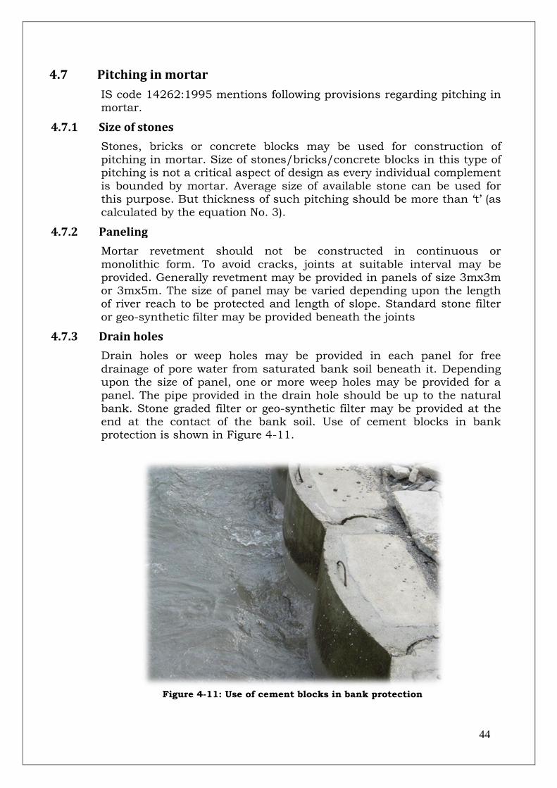
44
4.7 Pitching in mortar
IS code 14262:1995 mentions following provisions regarding pitching in mortar.
4.7.1 Size of stones
Stones, bricks or concrete blocks may be used for construction of pitching in mortar. Size of stones/bricks/concrete blocks in this type of pitching is not a critical aspect of design as every individual complement
is bounded by mortar. Average size of available stone can be used for this purpose. But thickness of such pitching should be more than „t‟ (as calculated by the equation No. 3).
4.7.2 Paneling
Mortar revetment should not be constructed in continuous or monolithic form. To avoid cracks, joints at suitable interval may be
provided. Generally revetment may be provided in panels of size 3mx3m or 3mx5m. The size of panel may be varied depending upon the length of river reach to be protected and length of slope. Standard stone filter
or geo-synthetic filter may be provided beneath the joints
4.7.3 Drain holes
Drain holes or weep holes may be provided in each panel for free
drainage of pore water from saturated bank soil beneath it. Depending upon the size of panel, one or more weep holes may be provided for a panel. The pipe provided in the drain hole should be up to the natural
bank. Stone graded filter or geo-synthetic filter may be provided at the end at the contact of the bank soil. Use of cement blocks in bank protection is shown in Figure 4-11.
Figure 4-11: Use of cement blocks in bank protection

45
4.8 Pitching by geo-textile bags
As per design practices following guidelines may be adopted for pitching by geo-textile bags.
4.8.1 Size of geo-bag
The pitching may also be provided using sand filled geo-synthetic bags. The size of bags may be 1.1m x 0.7m x 0.15m. The weight of such bags is around 126 kg which is generally safe for the velocity up to 3 m/s.
For higher velocities, size of Geo-bag may be higher so that weight of bag is higher than the required weight (worked out by the equation No.1). The geo-synthetic material should be safe against the UV rays
and abrasion.
4.8.2 Thickness of geo-bags pitching
The thickness of Geo-bag pitching may be decided as per procedure
given above at para 4.5.3. To summarize again, thickness of pitching should be more than „t‟ (as obtained by equation no. 3). Pitching may be provided in double layers of geo-bags (in loose) and single layer (encased
with nylon/polypropylene ropes).
4.8.3 Filter
If the pitching is being provided in geo-bags, then generally filter in not
provided because material of Geo-bags itself work as filter. But for safety purpose (for taking care of bank soil in joints), a geo-synthetic filter layers beneath the geo-bags may be provided. River bank before and
after geo-bags for bank protection is shown in Figure 4-12 and Figure 4-13
Figure 4-12: Bank before implementation of geo-bags
Figure 4-13: Bank after
implementation of geo-bags
4.9 Toe protection
IS code 14262:1995 mentions following provisions regarding toe
protection.
To prevent the sliding and failure of the revetment on slope, toe is required to be protected. This may be in the form of simple toe-key, toe
wall, sheet pile or launching apron
4.9.1 Toe key
Simple key may be provided at the toe (may be called as toe key) when

46
rock or un-erodible strata is available just below the river bed and the overlaying banks are erodible. The key is in the form of stone/bricks or
concrete blocks filled in the trench below the hard river bed for depth equal to the thickness of pitching “t” for proper anchorage. Sole purpose
of this key is to provide lateral support to the pitching. The key may be of mortar or in geo-bags, if the pitching is provided in mortar or geo-bags
4.9.2 Toe wall
When hard strata is available below the river bed at a reasonable depth, toe wall is recommended. The thickness of the toe wall depends upon height of wall and height of overlaying pitching. The toe wall may be
design as retaining wall and be constructed in masonry along with provisions of weep holes etc
4.9.3 Sheet piles and launching apron
When firm strata is not available at reasonable depth below the river bed, toe protection in the form of sheet pile or launching apron may be provided. The sheet pile may be made of RCC, steel or bamboo. The
sheet piles may be drilled below the river bed up to maximum scour depth.
Sheet piles are difficult to drive; therefore Launching apron is preferred and provided with revetment. Launching apron should be laid at low water level (LWL). The launching apron may be laid using the stones or
geo-bags. The stones/geo-bags in the apron should be designed to launch along the slope of scour and provide a protection layer so that scouring is checked. The size of launching apron should be such that it
should form a protection layer up to level of maximum scour depth. Slope of launching apron may be taken as 2H:1V. Filter below the
launching apron may also be provided so that river bed material is safe against suction. Typical toe protection using toe wall and launching apron is shown in Figure 4-14.
Figure 4-14: Toe protection using toe wall and apron
4.9.4 Size of launching apron
Width of the launching apron depends upon the scour depth below HFL.
Depth of scour below HFL (D) may be worked out using the following formula:

47
D = 0.473 (Q/f)1/3 -------------------------------------------------------------- (6.1) and D= 1.33 (q2/f)1/3 ------------------------------------------------------------------ (6.2) Where Q = design discharge in cumecs and q = design discharge per unit width or design discharge intensity in cumecs/m f is silt factor. Silt factor (f) may be calculated using the following formula f= 1.76 (d) 1/2----------------------------------------------------------------------- (7) where d is mean particle diameter of river material in mm
Generally scour depth (D) below HFL should be calculated using the
design discharge (equation no. 6.1). In some cases (for braided rivers) scour depth may be calculated using the design discharge intensity (equation no. 6.2).
Maximum scour depth (Dmax) below HFL= 1.5* Scour depth (D below HFL). Maximum Scour depth (Dmax) below LWL = (Dmax) below HFL – (HFL-LWL)
If the launching apron is being laid at LWL then width of the launching apron should be calculated using the following formula. Width of launching apron= 1.5 * (Dmax) below LWL
Thickness of launching apron (T) = 1.5* thickness of pitching (t).
In some cases, thickness of the launching apron is kept different from „T‟ due to size of crates etc (if launching apron is being provided in crated stones), then width of the launching apron may be revised keeping the volume of stones/geo-bags same per unit length of the apron.
4.10 Anchoring
IS code 14262:1995 mentions following provisions regarding anchoring.
Proper anchor is required for keeping the revetment in place and serving
the desired function. Upstream edge from where the revetment starts should be secured well to the adjoining bank. Similarly, downstream edge where the revetment ends also needs to be secured well to the
adjoining bank. Anchorage is also required to be provided on the top of submerged bank. If the top of bank is above HFL, the revetment should be provided above HFL with an adequate free board say 1.0 m. Under
such situation, anchorage at top is not required.
4.11 Merits and demerits of bank protection
CBIP-manual “River Behavior Management and Training Volume-I -1989” stipulates that owing to its extent, bank protection is usually
bulky and expensive. The failure of these type of works may be attributed to the over-economizing the cost of these type of works.
Cost can be reduced if protective measures are taken up immediately after signs of erosion of the banks. Otherwise deep scour develops, the river channel forms sharp and irregular bends and works become more
expensive. Once a deep channel is developed, it is preferable to divert the current from the bank.
Cost of river training works vary widely from one river to another and it
is very difficult to make a comparison. However for the protection of river bank and even already constructed embankment, bank protection
works become necessity of the time.

48
The other demerit of these type of works may be termed as shifting of the erosion prone location from protected location to some other
unprotected location in the d/s of the river
4.12 References 1. BIS code 14262:1995 2. Irrigation and Hydraulic structures- S. K. Garg
3. River Behavior Management and Training Volume-I (Central Irrigation and Power (CBIP), 1989)
4. Draft for revision of IS code 14262:1995

49
5.0 Design of Spurs/Groynes
5.1 General
CBIP-manual “River Behavior Management and Training Volume-I -
1989” stipulates that protection of banks is a part and parcel of river training works. This protection comes under anti erosion works.
Spurs/groynes are structures, constructed transverse to the river flow and extended from the bank into the river. Spurs/groynes, protruding into river come under purview of anti erosion works. These types of
works are provided to keep away flow from the erosion prone bank. The spurs are provided along with launching apron to prevent scouring under the water and consequent fall of spurs. A typical spur is shown in
Figure 5-1.
Figure 5-1: Spur built with boulders
5.2 General design features
IS code 8408:1994 mentions following provisions regarding planning of
spurs
5.2.1 Alignment
Spurs may be aligned either normal to flow direction or at angle pointing
towards u/s or d/s of the flow. A spur pointing u/s of the flow repels the flow away from the bank and is known as repelling type spur/groyne. When a short length spur changes only direction of flow without
repelling, it is known as deflecting spur/groyne. Spur pointing d/s of the flow attracts the flow towards the bank and is known as attracting spur/groyne. Generally repelling type or deflecting spurs are provided
for anti erosion measures. Repelling type spurs may be kept at an angle of 50 to 100 against the direction of flow. Alignment of spurs at bend is
shown in Figure 5-2.
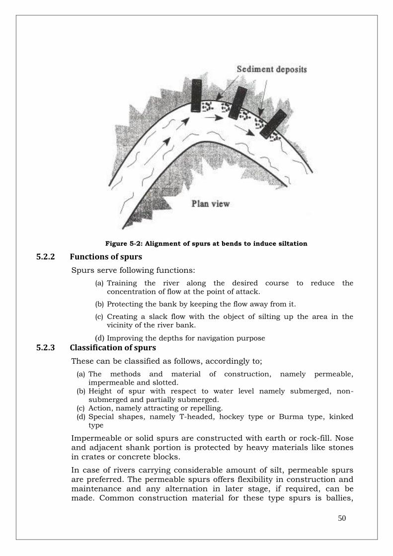
50
Figure 5-2: Alignment of spurs at bends to induce siltation
5.2.2 Functions of spurs
Spurs serve following functions:
(a) Training the river along the desired course to reduce the concentration of flow at the point of attack.
(b) Protecting the bank by keeping the flow away from it.
(c) Creating a slack flow with the object of silting up the area in the vicinity of the river bank.
(d) Improving the depths for navigation purpose
5.2.3 Classification of spurs
These can be classified as follows, accordingly to;
(a) The methods and material of construction, namely permeable, impermeable and slotted.
(b) Height of spur with respect to water level namely submerged, non-submerged and partially submerged.
(c) Action, namely attracting or repelling. (d) Special shapes, namely T-headed, hockey type or Burma type, kinked
type
Impermeable or solid spurs are constructed with earth or rock-fill. Nose and adjacent shank portion is protected by heavy materials like stones
in crates or concrete blocks.
In case of rivers carrying considerable amount of silt, permeable spurs
are preferred. The permeable spurs offers flexibility in construction and maintenance and any alternation in later stage, if required, can be made. Common construction material for these type spurs is ballies,

51
trees, bamboos and RCC porcupines. Generally RCC porcupine spurs are preferred as these are easy to construct, more durable and give
better performance. Permeable spurs made with timber are shown in Figure 5-3.
Figure 5-3: Permeable spurs constructed with timber
5.2.4 Orientation of spurs
IS code 8408:1994 & Draft for revision of IS 8408:1994 mention
following provisions regarding orientation of spurs.
Spurs/groynes can be used single or in series, depending upon the
reach of length to be protected. It can be used in combination with other river training measures. The spacing, orientation and length of spurs may be decided by the model study. Figure 5-4 illustrates a typical
orientation of groynes field for training a river.
Figure 5-4: Groynes field for training a river

52
5.3 Design of boulder spurs.
IS code 8408:1994 mentions following provisions regarding design of spurs
5.3.1 Length and spacing
The length of spur should be decided on the basis of availability of land on the bank. Effective length of the spur should be the portion which is likely to face/counter the river flow. Extra length given in the spur only
for the purpose of tagging the spur with high ground should not be taken into consideration for adoption as effective length of spur. Length shouldn‟t be less than that required to keep the scour hole formed at
the nose away from the bank. Thus assuming angle of repose of sand to be 2.5H:1V and anticipated maximum scour depth below river bed (ds),
the length should be more than 2.5xds. Short length may lead to bank erosion at u/s and d/s of the groyne due to formation of eddies at nose. On the other hand, too long spur may obstruct the river and may not
withstand the attack on account of heavy discharge concentration at the nose.
Normally the effective length of spur shouldn‟t exceed 1/5th of width of flow in case of single channel. In case of wide, shallow and braided rivers, the protrusion of spur in the deep channel should not exceed
1/5th of the width of channel on which the spur is proposed excluding the length over then bank.
The spacing of spurs is normally 2 to 2.5 times its effective length. For
site specific cases model studies may be conducted. The spurs located with proper spacing and length are shown in Figure 5-5.
Figure 5-5: Location of boulder spurs
5.3.2 Top level/top width and side slope
The top level of spur will depend on the type namely, submerged,
partially submerged or non-submerged and will be best decided by model study. In case of non-submerged spurs, the top level should be above design flood level with adequate free board. Free board may be
adopted as 1m/1.5m. In case non-submerged spur is tied with the embankment, then top level of embankment and top level of spur may
be kept same with similar free board and design HFL.
The top width of spur should be 3 to 6 m as per requirement. Side

53
slopes of the spur may be kept 2H:1V or 3H:1V depending upon the material being used for construction
5.3.3 Weight of stones for pitching
Stones/boulders used in pitching are subjected to hydrodynamic drag and lift forces. These destabilizing forces are expressed in terms of
velocity, tractive forces etc. the stabilizing forces acting against these are component of submerged weight of stones and downward component of force caused by contact of the stones.
The weight of stones on slopes (W in kg) may be worked using the formula given below.
W (in kg) = 0.02323*Ss*V6 /K* (Ss-1) 3 ---------------------------------------- (1) Where K (correction factor for slope) =[1-Sin2θ/Sin2Φ ]1/2 Ss = specific gravity of boulders (may be adopted as 2.65)
Φ = Angle of repose of material of protection works (adopted as 300 for
boulders) Θ = Angle of sloping bank 2 (H) :1 (V) (26.560) V = Velocity in m/s K = [1-Sin226.560/ Sin2300]1/2 = 0.447 Hence weight of stones for 2H:1V slope W (in kg) = 0.02323*Ss*V6/0.447* (Ss-1)3
5.3.3.1 Size of stone/ boulder.
Size of stone (Ds in m) may be determined from the following relationship.
Ds (in m) = 0.124* (W/Ss) 1/3 --------------------------------------------------- (2) Where: W = Weight of stone in kg Ss = Specific gravity of stone (may be adopted as 2.65) Minimum diminution of stones > Ds
Generally, the size of stone should be such that its length, width and thickness are more or less same ie stones should be more or less
cubical. Round stones or very flat stones having small thickness should be avoided
5.3.4 Thickness of pitching
Minimum thickness of pitching (t) or protection layer is required to withstand the negative head created by the velocity. This may be determined by the following equation.
Minimum thickness of pitching (t in m) = V2/2g (Ss-1) ------------------ (3) V= Velocity in m/sec g= Gravitational acceleration in m/sec2 Ss= Specific gravity of stone (Generally adopted as 2.65).
Therefore thickness of pitching should be higher than t (as obtained
above). Two layers of stones of minimum size „t‟ should be provided when pitching is being provided with boulders in loose
5.3.4.1 Pitching in crates
At high velocity, required weight of stones (to be found by equation no 1)

54
comes out to be higher, which makes handling and placing of stones a bit difficult. In such cases or in case when requisite sized stones are not
available, small size stones filled in GI (Galvanized Iron) wire crates may be used for pitching purpose. In this case single layer of GI wire crates
filled with stones having thickness more than „t‟ may be used as pitching. The specific gravity of the crate is different from the boulders due to presence of voids. Porosity of the crates (e) may be worked out
using the following formula.
e = 0.245+ 0.0864/ (D50) 0.21 ---------------------------------------------------(4) Where D50 = mean diameter of stones used in mm. let us assume D50 as 250 mm e = 0.245 + 0.0864/ (250)0.21
= 0.27
The opening in the wire net used for crates should not be larger than
the smallest size of stone used. The mass specific gravity of protection (Sm) can be worked out using the following relationship.
Sm= (1-e) *Ss------------------------------------------------------------------- (5)
This mass specific gravity may be used to work out the weight of the
crates and this weight should be more than weight of stone required, worked out by the equation no.1.
Crates should be laid with long dimension along the slope of the bank. Crates must be tied to each other by 5 mm GI wire as additional protection. If crates are being provided in layers then each layers should
be tied to each other at suitable interval using the 4 mm GI wire.
5.3.5 Filter
A graded filter of size 150 mm to 300 mm thickness may be laid beneath
the pitching to prevent failure by sucking action by high velocity. Geo-synthetic filter may also be used as that is easy to lay, durable, efficient and quality control is easy. A 150 mm thick sand layer over the Geo-
synthetic filter may be laid to avoid rupture of fabric by the stones.
5.4 Pitching in mortar
IS code 14262:1995 mentions following provisions regarding pitching in mortar.
5.4.1 Size of stones
Stones, bricks or concrete blocks may be used for construction of pitching in mortar. Size of stones/bricks/concrete blocks in this type of pitching is not a critical aspect of design as every individual complement
is bounded by mortar. Average size of available stone can be used for this purpose. But thickness of such pitching should be more than „t‟ (as
calculated by the equation no. 3).
5.4.2 Drain holes
Drain holes or weep holes may be provided for free drainage of pore water from saturated bank soil beneath it. The pipe provided in the

55
drain hole should be up to the natural bank. Stone graded filter or geo-synthetic filter may be provided at the end at the contact of the bank
soil.
5.5 Pitching by geo-bags
As per design practices following guidelines may be adopted for pitching by geo-textile bags.
5.5.1 Size of geo-bag
The pitching may also be provided using sand filled geo-synthetic bags. The size of bags may be 1.1 mx0.7mx0.15 m. The weight of such bags is around 126 kg which is generally safe for the velocity up to 3 m/s. For
higher velocities, size of geo-bag may be higher so that weight of bag is higher than the require weight (worked out by the equation no. 1. The
Geo-synthetic material should be safe against the UV rays and abrasion
5.5.2 Thickness of geo-bags pitching
The thickness of geo-bag pitching may be decided as per procedure given above at 5.3. To summarize again, thickness of pitching should be
more than „t‟. Pitching may be provided in double layers of geo-bags (in loose) and in single layer if encased using the nylon/polypropylene
ropes.
5.5.3 Filter
If the pitching is being provided in geo-bags, then generally filter in not provided because material of geo-bags itself work as filter. But for safety
purpose (for taking care of bank soil in joints), a geo-synthetic filter layers beneath the geo-bags may be provided. A spur using the geo-bags is shown in Figure 5-6:
Figure 5-6: Spur using geo-bags

56
5.6 Launching apron for spur
IS code 8408:1994 & 14262:1995 mentions following provisions regarding launching apron.
To prevent the sliding and failure of the spur due to scouring action by the river current, provision of launching apron is kept to take care of the scouring at nose and at shank (portion in the river) of the spur.
Launching apron should be laid at low water level (LWL). The launching apron may be laid using the stones or geo-bags. The stones/geo-bags in the apron should be designed to launch along the slope of scour and
provide a protection layer so that scouring is checked. The size of launching apron should be such that it should form a protection layer
up to level of maximum scour depth. Slope of launching apron may be taken as 2H:1V. Filter below the launching apron may also be provided so that river bed material is safe against suction
5.6.1 Size of launching apron
Width of the launching apron depends upon the scour depth below HFL. Depth of scour below HFL (D) may be worked out suing the following
formula.
D = 0.473 (Q/f) 1/3 -------------------------------------------------------------- (6.1) and D= 1.33 (q2/f) 1/3 ---------------------------------------------------------------- (6.2) Where Q= design discharge in cumecs and q= design discharge per unit width or design discharge intensity in cumecs/m. f is silt factor. Silt factor (f) may be calculated using the following formula f= 1.76 (d) 1/2---------------------------------------------------------------------- (7) where d is mean particle diameter of river material in mm
Generally scour depth (D) below HFL should be calculated using the design discharge (equation no.6.1). In some cases (for braided rivers)
scour depth may be calculated using the design discharge intensity (equation no. 6.2).
Maximum scour depth (Dmax) below HFL= 1.5* Scour depth (Dbelow HFL). Maximum Scour depth (Dmax) below LWL = (Dmax)below HFL – (HFL-LWL)
If the launching apron is being laid at LWL then width of the launching apron should be calculated using the following formula at different
locations of the groyne.
(i) Width of launching apron at nose = (2-2.5) * (Dmax) below LWL
(ii) Width of launching apron at transition from nose to shank and first 30 m to 60 m in u/s
= 1.5 * (Dmax) below LWL
(iii) Width of launching apron in shank portion for next 30 m to 60 m
= 1.0 * (Dmax) below LWL
(iv) Width of launching apron at transition from nose to shank and first 15 m to 30 m in d/s
= 1.0 * (Dmax) below LWL

57
Thickness of launching apron (T) = 1.5* thickness of pitching (t).
In some cases, thickness of the launching apron is kept different from „T‟ due to size of crates etc (if launching apron is being provided in crated stones), then width of the launching apron may be revised keeping the volume of stones/geo-bags same per unit length of the apron.
Figure 5-7: Spur along with bank protection using geo-textile
5.7 Design of boulder spur: an illustration
The design of typical boulder spur has been provided in the following method.
Design Discharge Q (assumed) = 20000 cumecs
Gravitational Acceleration g = 9.81 m/sec2
Design HFL (Assumed) = 100.00 m
Observed LWL (Assumed) = 96.00 m
Stream Velocity V (Assumed) = 3.00 m/sec
Mean Dia of river bed material d (assumed) = 0.30 mm
Silt Factor f= 1.76* (d) 1/2 = 0.96
Angle of sloping bank (2H:1V) θ = 26.56 0
Angle of repose of protection material Φ = 30 0
Value of K=[1-Sin2θ/ Sin2Φ ]1/2 = 0.447 Specific gravity of boulders Ss = 2.65 Weight of boulders W=0.02323*Ss*V6/ (K* (Ss-1) 3) = 22.349 kg
Size of boulder= 0.124 (W/Ss) 1/3 = 0.25 m
Thickness of pitching (T) for negative head criterion=V2/2g (Ss-1) = 0.28 m
Thickness of pitching (=2*0.3=0.60m) = 0.60 m
Design of Launching Apron (to be laid at LWL)
Scour Depth below HFL D = 0.473* (Q/f) 1/3 = 13.015 m
Max. Scour Depth below HFL at Nose (Dmax) = (2.0-2.5) *D (adopted as 2D) = 26.030 m
Max. Scour Depth below HFL at transition from nose to shank and 1ST 30 m to 60 m U/S (D'max) = = 19.523 m

58
1.5*D
Max. Scour Depth below HFL for next 30 m to 60 m in U/S (D''max) = 1.0*D = 13.015 m
Max. Scour Depth below HFL for transition from nose to shank and 1ST 15 m to 30 m D/S (D'''max) = 1.0*D = 13.015 m
Width of Launching Apron at nose= 1.5*[Dmax- (HFL-LWL) ] = 33.045 m
Adopt 23 crates of size 1.5mx1.5mx0.45 m (total width of launching apron=23*1.5=34.5) = 34.50 m
Width of Launching Apron for transition from nose to shank and up to 60-90 m U/S =1.5*[D'max- (HFL-LWL) ] = 23.285 m
Adopt 16 crates of size 1.5mx1.5mx0.45 m (total width of launching apron=16*1.5=24) = 24.00 m
Width of Launching Apron for next 30 m to 60 m in U/S =1.0*[D''max- (HFL-LWL) ] = 9.015 m
Adopt 6 crates of size 1.5mx1.5mx0.45 m (total width of launching apron=6*1.5=9) = 9.000 m
Width of Launching Apron for transition from nose to shank and 1st 15 m to 30 m D/S =1.0*[D'''max- (HFL-LWL) ] = 9.015 m
Adopt 6 crates of size 1.5mx1.5mx0.45 m (total width of launching apron=6*1.5=9) = 9.000 m
Thickness of Launching Apron (loose boulder)
=1.5* Thickness of pitching = 0.900 m
5.8 Permeable spurs
Draft for 2nd revision of IS code 14262:1995 mentions following provisions regarding permeable spurs
5.8.1 Introduction
Unlike impermeable spurs which do not allow any water to flow through
its body (except seepage due to differential head), permeable groynes made of ballies, bamboos, trees, porcupines etc. are pervious enough so that the flow takes place across the groynes through their bodies. As
found experimentally (by Lagasse-), up to 35% permeability (defined as the area of opening to the total area of flow intercepted by spurs i.e. the
product of its length normal to the flow and the depth of flow), the behavior of a permeable spur, as far as its effectiveness in bank protection is concerned, is almost similar to that of an impermeable
groyne. As the permeability increases, the length of the protected reach of bank gets reduced since eddies are reduced. As the flow passes
through the permeable groynes, the micro eddies and the turbulence produced downstream of the groynes cause dampening of flow (due to energy dissipation) and consequent reduction in velocity. As a result the
erosive power of the flow is reduced.
Permeable spurs are usually made in groups and may be used in combination with an upstream impermeable spur acting as flow
deflector and sheltering the permeable spurs from any direct attack on them. They may also be constructed in combination with longitudinal
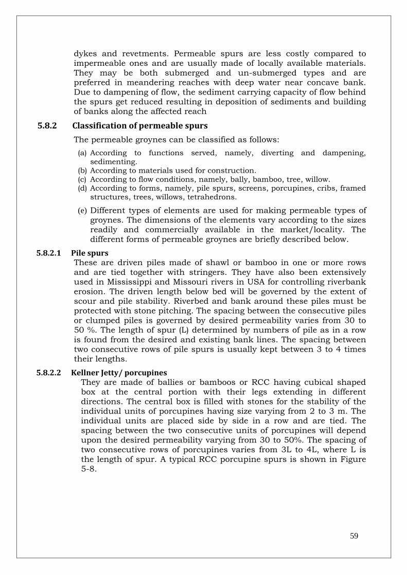
59
dykes and revetments. Permeable spurs are less costly compared to impermeable ones and are usually made of locally available materials.
They may be both submerged and un-submerged types and are preferred in meandering reaches with deep water near concave bank.
Due to dampening of flow, the sediment carrying capacity of flow behind the spurs get reduced resulting in deposition of sediments and building of banks along the affected reach
5.8.2 Classification of permeable spurs
The permeable groynes can be classified as follows:
(a) According to functions served, namely, diverting and dampening, sedimenting.
(b) According to materials used for construction. (c) According to flow conditions, namely, bally, bamboo, tree, willow. (d) According to forms, namely, pile spurs, screens, porcupines, cribs, framed
structures, trees, willows, tetrahedrons.
(e) Different types of elements are used for making permeable types of groynes. The dimensions of the elements vary according to the sizes readily and commercially available in the market/locality. The
different forms of permeable groynes are briefly described below.
5.8.2.1 Pile spurs These are driven piles made of shawl or bamboo in one or more rows
and are tied together with stringers. They have also been extensively used in Mississippi and Missouri rivers in USA for controlling riverbank
erosion. The driven length below bed will be governed by the extent of scour and pile stability. Riverbed and bank around these piles must be protected with stone pitching. The spacing between the consecutive piles
or clumped piles is governed by desired permeability varies from 30 to 50 %. The length of spur (L) determined by numbers of pile as in a row
is found from the desired and existing bank lines. The spacing between two consecutive rows of pile spurs is usually kept between 3 to 4 times their lengths.
5.8.2.2 Kellner Jetty/ porcupines They are made of ballies or bamboos or RCC having cubical shaped box at the central portion with their legs extending in different
directions. The central box is filled with stones for the stability of the individual units of porcupines having size varying from 2 to 3 m. The individual units are placed side by side in a row and are tied. The
spacing between the two consecutive units of porcupines will depend upon the desired permeability varying from 30 to 50%. The spacing of
two consecutive rows of porcupines varies from 3L to 4L, where L is the length of spur. A typical RCC porcupine spurs is shown in Figure 5-8.

60
Figure 5-8: A typical RCC porcupine spur
5.8.2.3 Cribs
These are similar to porcupines with the difference that the ballies/bamboos from a pyramid type structure with a box at the bottom
for holding stones for the stability of individual units. The spacing between the consecutive cribs and the consecutive rows of cribs will be similar to that of porcupines.
5.8.2.4 Balli/bamboo frames
A framed structure made with driven poles of bamboos/shawls with longitudinal, cross and diagonal bracings is constructed across the flow.
5.8.2.5 Tree spurs
Locally available tree branches (hung with their trunks) up and branches/leaves down tied with ropes across a framed structure are
found to be highly effective in dampening flow velocity and entrapping suspended sediments in the flowing water.
5.8.2.6 Willow/ brushwood spurs
Willow (also called as Tarza or Shirkanda) is a type of bush available in plenty across the country, has sufficient rigidity and strength are not easily decomposed. These or other brushwood available locally are filled
and weighed by heavy stones in alternate layers within the framed structures. Such spurs however, entrap sediments and lose their initial
permeability and eventually behave like impermeable spurs with deep scour near their noses.
5.8.3 Submergence of spurs
Unlike impermeable spurs which are un-submerged with freeboard,
permeable spurs may be either un-submerged or submerged. Submergence up to 50% is acceptable for porcupines, 20% for cribs and
5% to 10% for tree and willow spurs with framed structure.
5.8.4 Length and spacing of permeable spurs
Considerations similar to those as already discussed for impermeable groynes under clause 5.2 should be followed in deciding length and
spacing of permeable spurs. Very long spurs should not be provided due to difficulties in construction as well as maintenance against scour. The
61
spacing of spurs will be determined by their lengths. Shorter spurs at closer interval is desirable in curved outer banks of a meandering
stream compared to those in the straight reach of rivers.
5.9 Limitation of spurs
CBIP-manual “River Behavior Management and Training Volume-I -1989” stipulates that the success of repelling type spur depends upon
the extent and the quickness with which scour occurs at the nose, and also on how quickly the pockets between the spurs get filled up with sediment. This condition make the impermeable groynes useless in
boulder rivers, in which the rate of silt deposition may be slow or in flashy rivers in which floods rise and fall so quickly that desired silting
doesn‟t take place. The spurs can‟t be relied upon to afford immediate protection.
It is also observed that silting between the successive spurs can be
accomplished only when their lengths are sufficient. Short spurs don‟t offer sufficient protection.
In case of narrow and deep rivers, the cost of solid spurs above high water is substantial. Moreover, because of the narrow width of rivers, solid spurs can‟t be extended much as otherwise they can cause
harmful conditions on the opposite bank or further d/s. In such cases submerged spurs are recommended. As the tractive force on the slope is maximum at 1/3 depth from the bottom, the top of spur should be kept
at least half of depth of water. A single submerged spur may not be as effective as series of submerged spurs. Since flow over the spurs
produces turbulence and scour below them, silting may not take place as rapidly as required. It may be concluded that permeable spurs are effective only in rivers which carry heavy suspended load
5.10 References 1. IS code 8408:1994. 2. Irrigation and Hydraulic structures- S. K. Garg. 3. River Behavior Management and Training Volume-I (Central
Irrigation and Power (CBIP), 1989). 4. Draft for revision of IS code 8408:1994

62
6.0 Design of RCC Porcupines- Screens/ Spurs/ Dampeners
6.1 General
Protection of banks is a part and parcel of river training works. This
protection comes under anti erosion works. Permeable structures envisaging construction of RCC porcupine screens/spurs/ dampeners
are a cost effective alternative to the impermeable bank protection works for the rivers carrying considerable amount of silt. RCC porcupine is a prismatic type permeable structure, comprises of six members of made
of RCC, which are joined with the help of iron nuts and bolts.
Permeable screens, spurs, dampeners are the main type of permeable structures in vogue. Prima facie, the purpose, overall behavior and
layout of the above mentioned structures can be compared to those of submersible bunds, spurs and revetment respectively. The permeable
structures can be used either independently or with a support of other impermeable boulder structures or river training and bank protection measures. Depending upon the purpose, the permeable structures like
RCC porcupines may be constructed in transverse or parallel to direction of flow. Typical sketch of a RCC porcupine is as given at Figure 2-3.
6.2 General design features
General design features of RCC porcupine screens/spurs/ dampeners are given below in detail.
6.2.1 Concept
Dampening of velocity is achieved by using the permeable structures. If
the flow is sediment laden, siltation is induced in the slack flow region and the channel is shifted away from the protected reach.
If the flow is not carrying the sufficient sediments, only dampening of velocity can result. Sedimentation may not be achieved near the protected reach.
Only partial obstruction to the flow of about 15 to 20% only is envisaged in the design. Higher obstruction causes more diversion of flow resulting
in undesired scouring around the proposed structures, particularly at the nose portion. Additional protection to the nose and flanks is required to avoid such scour. Therefore, obstruction more than 20% is
avoided.
Submergence of RCC porcupine screens/spurs/ dampeners may be kept up to 50% of depth of flow. For example, single layer of RCC
porcupines, comprising 3 m long members is sufficient for depth of water till 6 m.

63
6.2.2 Functions of permeable structures Permeable structures serve one or more of the following functions:
(a) Training the river along the desired course. (b) Reducing the intensity of flow at the point of river attack. (c) Creating a slack flow to induce siltation in the vicinity of the permeable
structures and in the d/s reach. (d) Providing protection to the bank by dampening the velocity of flow along the
bank.
Use of RCC porcupines for slackening the flow is shown in Figure 6-1.
Figure 6-1: RCC porcupines for slackening the flow
6.2.3 Structural elements
The elements used in the RCC porcupine screens/spurs are as under:
(a) Members: The porcupines are made of RCC members/elements. These members are casted in-situ at the site or location near the site. Generally six members are used to construct one porcupine. The size of one member is kept as 3mx0.1mx0.1m or 2mx0.1mx0.1m. These members are joined with the help of Nails.
(b) Nails: Standard commercially available nails of length 100 mm to 150 mm
are used to join the porcupine members. Double nailing at critical joints may be provided.
(c) GI Wire: 4 to 5 strands of 4 mm GI wire should be used for inter-connecting the porcupines and may be anchored with the ground. Alternatively, 12 mm 3-4 strands wire ropes should be used for the interconnecting the porcupines.
Use of nylon ropes instead of GI wires may also be tried. But these are susceptible to disintegration in presence of UV rays. In view of this, UV stabilized nylon ropes may be tried instead of GI wires due to their
better usability and flexibility and non-corrosive behavior. A typical RCC porcupine screen is shown in Figure 6-2.

64
Figure 6-2: Typical RCC porcupine screen
6.2.4 Layout in plan
As already pointed out that the RCC porcupine screens are laid in the form of screens, spurs and dampeners, the layout for each of the
structure is as under
6.2.4.1 The RCC porcupine spurs
(a) The porcupines (comprising of six members of size 3mx0.1mx0.1m) are laid in a row across the river bank protruding into the river at spacing generally adopted as 3m c/c. If size of member is 2m x 0.1m x 0.1m, then spacing between the porcupines may be kept as 2m c/c.
(b) Each porcupine spur is made up of 3 to 7 rows of porcupines (Higher rows for higher flow). The spacing of rows is kept at same as spacing of each porcupine in each row (3 m or 2 m c/c depending upon size of the member).
(c) If the flow depth is more than 6 m, RCC porcupine spurs may be provided in double vertical layers.
(d) On a straight reach, RCC porcupine spurs are placed at 3 to 5 times the length of spur. On a curved channel, the spacing can be kept as 2 to 4 times the length of spur.
(e) The length of spur into the river shouldn‟t exceed the 1/5 of the width of the flow. Generally length of spurs may be kept less than 100m to 150 m.
(f) In order to resist the tendency of outflanking, additional porcupines may be provided along the sloping bank at u/s and d/s of the RCC porcupine spurs.
(g) At least three RCC porcupine spurs may be provided for a reach to be protected. A single permeable spur is generally not effective.
(h) At several locations facing severe erosion, where revetment with apron is not feasible or justified due to space and cost constraint, provisions of RCC porcupine spurs along with porcupine dampeners/screens along the eroded bank may be provided.
(i) The practice of providing one or two additional spurs u/s and d/s of the eroding reach, pointing towards u/s with reference to flow may be followed for the RCC porcupine spurs also. Typical sketch of RCC porcupine spur
is as under in Figure 6-3. A RCC porcupine spur is also shown in Figure 6-4.

65
Figure 6-3: A typical porcupine spur
.
Figure 6-4: RCC porcupine spur
6.2.4.2 The RCC porcupine dampeners
(a) The porcupines (comprising of six members of size 3mx0.1mx0.1m) are laid in a row along the river bank functioning similar to revetment at
spacing generally adopted as 3m c/c. If size of member is 2mx0.1mx0.1m, then spacing between the porcupines may be kept as 2m c/c.
(b) The spacing of rows is kept at same as spacing of each porcupine in each row (3 m or 2 m c/c depending upon size of the member).
(c) For a maximum depth of flow up to 3 m, 2 rows of porcupines are laid along the either side of toe as dampeners.
(d) For a depth of flow more than 3 m, rows of porcupines are added across the bank line up to HFL @ spacing of 3 m or 2 m depending upon the length of member. Additional rows (2 or 3) may be provided at the top of bank in case of submerged river bank during floods.
Typical sketch of RCC porcupine dampener is as under in Figure
6-5.

66
Figure 6-5: Typical RCC porcupine dampener
6.2.4.3 RCC porcupine screens
(a) The RCC porcupine screens are used to block the secondary channels. (b) Each porcupine screen is made up of 5 to 9 rows of porcupines (Higher
rows for higher flow). The spacing of rows is kept at same as spacing of each porcupine in each row (3 m or 2 m c/c depending upon size of the member).
(c) At least two screens are provided to block the secondary channel. A single
screen is generally not found effective. (d) One screen is normally provided at the entrance of the secondary channel.
The second screen is provided at a distance of 1 to 1.5 times width of the secondary channel.
(e) The screens are constructed covering a part or the whole width of secondary channel. If the screen covers the whole width, the screens are extended on both banks for a length 1/3rd of the channel width.
(f) Depending upon the importance, the possibility of development of bypass channel, a third screen can also be provided further d/s at a suitable location.
(g) If the screens are located near the bank, the extension towards bank should be restricted to the design HFL.
Typical sketch of RCC porcupine screen is as under in Figure 6-6.

67
Figure 6-6: Typical RCC porcupine screen
6.2.4.4 Protection to the permeable structures
(a) The elements ie RCC porcupine members may be tied with each other by GI wire or nylon ropes (UV stabilized). The tie ropes may be duly anchored to the bank and at the nose with the help of suitable anchor. Depending upon the length of the screen/spur/dampeners, intermediate anchors may be provided at an interval of 15 m to 20 m along the length of structure on u/s side.
(b) No bed protection is needed for the RCC porcupine structures. Sinking of these structures in riverbed is a welcome feature, which adds up to the stability during floods resulting in better performance.
(c) In order to divert the flow and reduce pressure on the RCC porcupine works, wherever feasible, pilot channels should be provided in additional to the river training works
6.3 Limitation of RCC porcupines
(a) In case of high velocity flows, implementation of only RCC porcupine works is not favored. However, use of RCC porcupine works in between the reach of two solid boulder spurs is more effective
(b) .Generally additional quantities of RCC porcupines is kept for placing the RCC porcupines in 2nd year or during consequent years at locations where partial silting has been taken place after implementation of RCC porcupines in 1st year. In the absence of placing additional porcupine, the silted region near the bank may not become firm.
6.4 References 1. Guidelines for planning and design of Permeable structures in
alluvial rivers

68
7.0 Design of Drainage Improvement Works
7.1 General
IS code 8835:1978 stipulates that drains are constructed with the
object of relieving excess water from agricultural and other areas and disposing of surplus water which is not required for normal agricultural
operations. The proper disposal of surplus rain water is also essential to avoid its percolation down to the water level which may otherwise lead to rise in the water table thereby aggravating or creating the problem of
water logging.
The drains may be natural or artificial. As per accepted principles, these are generally aligned along the valley lines between ridges. However, in
some cases in order to reduce the length of the drain or to have proper outfall conditions, the drains are taken across valleys. These are known
as forced or diversion reaches.
Task Force on Flood Management /Anti Erosion Measures (2004) also stipulated that water logging due to poor drainage system particularly
in flat lands is one of the reasons of flood problem in the area resulting in damages to crops and adverse impact and other activities. Providing
adequate drainage system where natural drainage system is insufficient is the basic requirement to lessen the distress caused by floods in the area. A cross drainage work is shown in Figure 7-1.
Figure 7-1: A cross drainage work
7.2 Planning of drainage improvement works
Various aspects related to planning of drainage/channel improvement works including data requirement, degree of protection, classification of
drains, alignment of drain, capacity of drains etc. are described in paras below.
7.2.1 Requirement of data
For the planning of the drainage/channel improvement following data is required.

69
7.2.1.1 Topographical data
Index plan showing area affected, bank slope, type of soil, cropping
pattern, catchment area, plan and section of earlier executed works.
7.2.1.2 Hydrological and meteorological data
Discharge, gauge, flow depth, silt content, velocity, cross sections and
long section of river, rainfall data etc.
7.2.1.3 History of past drainage congestion
Area of submergence, extent of submergence, duration of submergence
etc.
7.2.2 Degree of protection
IS Code 8835:1978 stipulates that drains may be designed for 3 day rainfall of 5 year return period. However, in specific cases requiring
higher degree of protection, return period of 10 or 15 year may also be adopted. Adoption of higher return period rainfall should be justified in
term of economics. Cross drainage works should be designed for 3 day rainfall of 50 year return period. Construction of cross drain under the embankment is shown in Figure 7-2.
Figure 7-2: cross drain under the embankment
7.3 Classification of drains
IS Code 8835:1978 stipulates that the drains are broadly classified into the following categories according to the purpose for which these
are constructed:
(a) Outfall drains- These are the main drains out falling into a nallah or a river from a particular catchment.
(b) Link Drains- These are branch drains draining sub-catchment into the

70
outfall drain. These are aligned along subsidiary valley lines. (c) Field drains- These are small drains draining individual or a group of
fields into the link drains. (d) Ditch drains- These are constructed to drain the water by connecting
borrow pits along roads, railway lines, etc. (e) Cunnette- This is a small drain constructed in the bed of main drain at
level lower than the normal bed levels of the main drain for carrying non-monsoon/seepage discharge without allowing it to spread across the entire section of the main drain.
(f) Seepage drains- These are constructed along the canals to collect the seepage water from the canal embankments and to drain it either directly into a natural outfall or into a carrier drain.
An embankment with sluice is shown in Figure 7-3.
Figure 7-3: Embankment with sluice
7.4 Alignment of drains
IS code 8535:1978 envisages following guidelines for the alignment of the drainage channel.
The drains should generally follow the drainage line ie. lowest valley
line. As far as possible the alignment of the main or outfall drain should be in the centre of the area to be drained. If the alignment
crosses any depressions, ponds or marshes, the drain should not pass through these, as apart from the difficulties in excavation, it affects the hydraulic performance of the drain. In such cases, it is preferable to
take the drain away from the depression or pond, and suitably connect it to the drain if it is required to drain the pond or depression.
In selecting alignments, care should be taken to see that as far as
possible these do not pass through village habitation. In the forced reaches, care should be taken to see that the embankments of the
drains are not of an excessive height in order to minimize the danger of flooding in the event of breaches in the embankments.
As far as possible, the alignment of the drain should be such that the
full supply level is below the natural surface level. A sluice with gates

71
is shown in Figure 7-4: A gated sluice .
Figure 7-4: A gated sluice
7.5 Capacity /design discharge of drains. IS code 8535:1978 envisages following guidelines for capacity/design discharge of the drainage channel.
Normally the drain is provided to accommodate the design discharge
where drains follow natural valley lines. In such cases, no embankments should be provided along the drain so as to allow free
flow of water from the surroundings areas. Wherever embankments are necessary for accommodating a portion of the design discharge or where disposal of excavated soil will be very costly, large gaps should
be provided in the embankments on either side so as to allow unrestricted inflows, and in case of discharges higher than the channel
capacity, the water should spill over the area and return to the channel freely when the discharge in it recedes. In the forced or diversion reaches, embankments on both sides are, however, provided
as the design discharge cannot be accommodated within the cut section of the drain. However, even in such cases attempts should be made by selecting a proper alignment to keep the height of the
embankments to the minimum. In such cases, inlets of adequate size should be provided in the embankments to admit the water from
surrounding areas. A typical drain is shown in Figure 7-5.

72
Figure 7-5: A typical drain
Intensity of Rainfall- Analysis of the storm rainfall throughout the
country indicates that generally the duration of the storm is about 3 days. Therefore, for design of the drains, a storm rainfall of 3 day duration should be taken
7.5.1 Design frequency of rainfall
In fixing the design capacity of the drain the following factors have to be taken into account:
a) Economics- Drains of a bigger size for catering a rainfall of infrequent occurrence prove to be costly compared to the benefits. Drains are never designed to cater for the worst conditions. In other words, in any drainage project, occurrence of damage at periodical intervals is to be accepted.
b) Performance- The experience indicates that drains of a bigger size tend to deteriorate fast, as these are not required to carry the design discharge frequently. Consequently in carrying smaller discharge, drains tend to get silted soon. On the other hand, Drains of a smaller size remain in a better condition and can occasionally carry higher discharges with marginal scour of bed and sides and encroachment on free board.
c) Land requirement- On account of small land holdings, bigger drains
involve larger land acquisition resulting in a permanent loss of the cultivated land.
d) Design frequency- Generally the drains should be designed for three day rainfall of 5 year frequency. Studies carried out indicate that 5 year frequency gives optimum benefit cost ratio. However, in specific cases requiring a higher degree of protection, the frequency of 10 or 15 year can also be adopted. Adoption of such higher frequencies will need to be justified in terms of the economics
7.5.2 Period of disposal
The period of disposal of the excess rainfall is entirely dependent on the tolerance of individual crops. Crops Like paddy can generally stand
submersion for a period of 7 to 10 days without suffering any significant damage. Therefore, in paddy growing areas, the drainage should aim at disposing of the rain water in a period varying from 7 to

73
10 days. Based on experience the following periods of disposal are recommended.
# Crops Period of Disposal
(i) Paddy 7 to 10 days
(ii) Maize, bajra and other similar crops
3 days
(iii) Sugarcane and bananas 7days
(iv) Cotton 3 days
(v) Vegetables 1 day (in case of vegetables, 24 hour rainfall will have to be drained out in 24 hours)
7.5.3 Run-off
Run-off coefficients depends on the type of soil, crops, general topographical conditions like land slopes, etc. In plain areas, the run-
off percentage is generally of the order of 15 to 20. In semi- hilly areas the percentage may be higher. Until precise data becomes available, the following run-off coefficients for different soils are recommended for
plain areas.
# Type of catchment Run-off Coefficient
(i) Loam, lightly cultivated or covered 0.40
(ii) Loam, largely cultivated and suburbs with gardens, lawns, macadamized roads
0.30
(iii) Sandy soils, light growth 0.20
(iv) Parks, lawns, meadows, gardens, cultivated area 0.05-0.20
(v) Plateaus lightly covered 0.70
(vi) Clayey soils stiff and bare and clayey soils lightly covered 0.55
7.5.4 Run-off for composite crops
In large areas, there are often different types of crops grown. In such cases, the field and link drains can be designed on the basis of the
crops grown in a particular area. For the outfall drain, either a composite discharge can be worked out or the total discharge can be worked out by taking into account the discharges from individual link
drains. As the area grows larger, the chances of synchronization of discharge from the entire area become less. As such, working out a composite discharge may also serve the purpose. However, individual
cases will have to be studied on their own merit. A typical gated sluice for high embankment is shown in Figure 7-6.
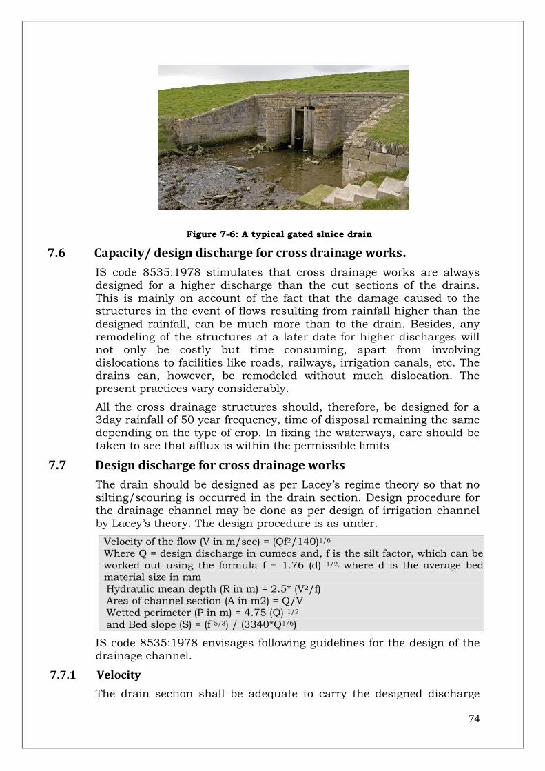
74
Figure 7-6: A typical gated sluice drain
7.6 Capacity/ design discharge for cross drainage works.
IS code 8535:1978 stimulates that cross drainage works are always designed for a higher discharge than the cut sections of the drains.
This is mainly on account of the fact that the damage caused to the structures in the event of flows resulting from rainfall higher than the
designed rainfall, can be much more than to the drain. Besides, any remodeling of the structures at a later date for higher discharges will not only be costly but time consuming, apart from involving
dislocations to facilities like roads, railways, irrigation canals, etc. The drains can, however, be remodeled without much dislocation. The present practices vary considerably.
All the cross drainage structures should, therefore, be designed for a 3day rainfall of 50 year frequency, time of disposal remaining the same
depending on the type of crop. In fixing the waterways, care should be taken to see that afflux is within the permissible limits
7.7 Design discharge for cross drainage works
The drain should be designed as per Lacey‟s regime theory so that no
silting/scouring is occurred in the drain section. Design procedure for the drainage channel may be done as per design of irrigation channel by Lacey‟s theory. The design procedure is as under.
Velocity of the flow (V in m/sec) = (Qf2/140)1/6
Where Q = design discharge in cumecs and, f is the silt factor, which can be worked out using the formula f = 1.76 (d) 1/2, where d is the average bed material size in mm Hydraulic mean depth (R in m) = 2.5* (V2/f) Area of channel section (A in m2) = Q/V Wetted perimeter (P in m) = 4.75 (Q) 1/2
and Bed slope (S) = (f 5/3) / (3340*Q1/6)
IS code 8535:1978 envisages following guidelines for the design of the drainage channel.
7.7.1 Velocity
The drain section shall be adequate to carry the designed discharge

75
and the velocity shall be non-silting, non-scouring to be determined by Manning‟s formula.
7.7.2 Discharge capacity of the drain
In order to obtain the discharge capacity of a drain it is necessary to know the mean velocity of flow as obtained above which when
multiplied by the area of the cross section of the drain in square meters will give the discharge in m3/s.
7.7.3 Side slopes
In selecting the side slopes for the drain, it will be necessary to
consider the kind of material through which the drain is to be excavated. Generally side slopes of 1.5H : 1V are provided.
7.7.4 Cross sections of the drain
Although deeper sections of the drain may be desirable, the width to
depth ratio should be so selected that the section is both hydraulically efficient as well as economical in excavation. In the case of drains with
embankments, the berm width equal to the depth of the drain, subject to a minimum of 1 m should be provided between the toe of the embankment and the section of the drain. The top of the
embankments should be 1 m higher than the design full supply level. Wherever, there is likelihood of backing up effect on account of floods
in a river into which the drain outfalls, the top of the embankments should be so designed that the flood levels on account of back water conditions are accommodated within the section over which the
minimum freeboard is to be provided.
7.7.5 Fixation of full supply level (FSL) at outfall
Whenever the drain is out falling into a river, the FSL should be slightly higher than the dominant flood level. The dominant flood level
is the stage of river/outfall which is (a) attained and not exceeded for more than 3 days at a time; and also (b) attained and not exceeded
75% of time over a period of preferably not less than 10 years. In cases where the topography permits, the FSL can be above the highest flood level. However, if such a level results in flatter slopes or in FSL
becoming higher than the natural ground level, FSL at outfall should be kept slightly above the dominant flood level. In such cases, there
will be backing up in the drain when the river rises above the dominant flood level. Such occurrences being infrequent and of short duration can be tolerated. Care shall, however, be taken in
determining the dominant flood discharge and the level.
7.7.6 Hydraulic slope
The FSL of the drain as far as possible should be at or below the ground level. Where it cannot be ensured, the FSL should in no case
be more than 0.3 m above the average ground level at the starting point of the drain. The hydraulic should then be determined adopting
the stipulation and the criteria laid down for fixation of FSL at outfall.

76
The hydraulic slope should normally be such as to provide permissible velocities as indicated in 7.7.1 above.
7.7.7 Tidal lockage
In the case of drains out falling into rivers subjected to tidal influence, the reaches of the drains which will be subjected to tidal lockage
should be determined. In these reaches capacity of the drains should be increased to provide for duration of the tidal lockage gradually diminishing from the outfall towards the upstream. For this purpose, it
will be necessary to plot the dominant tidal curves. The FSL of the drains in such cases should normally be fixed at mean tide levels. This will also be known as cut off level. This will be level at which the drain
will again start discharging during the ebb tide. This level will always be higher than the cut off level. In major outfall drains, an outfall
regulator should invariably be constructed to prevent tides entering the channel, which will result in silting of the drains.
7.7.8 Falls
Normally no falls should be provided in drains except in rare cases
where there is a sudden appreciable drop in the natural surface level or where the FSL s likely to be more than natural surface level without
provision of falls.
7.8 Longitudinal section
IS code 8535:1978 envisages following guidelines for deciding the longitudinal profile of drainage channel.
7.8.1 Collection of data
The following data should be collected while carrying out surveys along
different alternatives alignments of drains:
(a) Cross sections at every 150 m. (b) Natural ground, design bed and full supply levels at every 150 m. (c) Locations of inlets of link/field drains with related hydraulic data. (d) Full data of all crossings like roads, railways, irrigation canals, etc. (e) Representative soil samples to determine the probable stable side slopes. (f) Ground water levels at a distance of about 2 km. (g) Boundaries and slopes of the areas needing drainage. (h) Existing drains. (i) Location and elevation of all depressions, drains, mounds and ridges. (j) Location and elevation of possible inlets (outfalls). (k) Area that will drain into each part of the system. (l) Flood data of Outfall River and study of backwater effect of flood
7.8.2 Preparation of longitudinal section
(a) Fix outfall level considering the dominant flood levels in the river/drain and the likely backing up.
(b) Hydraulic slope to be determined on the basis of the ground levels, permissible submersion and the outfall levels determined in (a).
(c) Plot the natural ground levels, design bed levels, full sully levels and the backwater profiles, if any.
(d) Divide the drain in convenient reaches between inlets sites o the junction

77
of tributary/link drains. The capacity of the drains in each of these reaches should be uniform. The capacity will change with the addition of discharge from tributary/link drains
7.9 Channel improvement by dredging
The method of improving the channel by improving the hydraulic conditions of the river channels by desilting, dredging, lining etc., to enable the river to carry its discharges at lower levels or within its
banks has been often advocated but adopted on a very limited extent because of its high cost and other problems especially because the success of this method of river improvement for lowering flood levels
depends on outfall conditions which can‟t be changed appreciably.
Dredging operations of the Brahmaputra, which were undertaken in
the early seventies on an experimental basis, were discontinued because of their prohibitive cost and limited benefits. Dredging in selected locations may perhaps be considered as a component of a
package of measures for channel improvement to check the river bank erosion subject to techno-economic justification. It may be
economically justifiable as a method for channel improvement where navigation is involved. Dredging is sometimes advocated for clearing river mouth or narrow constrictions.
The Task Force on Flood Management /Anti Erosion Measures (2004) also recommended that “desilting operations may be carried out for improvement of carrying capacity of drainage channels downstream of sluices at their outfalls into rivers and in upstream selectively, if absolutely essential. Desilting at mouth of the tributaries out falling into main rivers, at the mouth of rivers out falling into sea and at other critical locations may also be taken up selectively after detailed studies”.
7.10 Methodology for determining the dominant flood level: an illustration
As per example given in IS Code 8835:1978 the method for determining the dominant flood level has been explained in table
below:
The record of gauge hydrographs of a river, as available from 1962 to
1971. The levels which were attained and not exceeded for more than 3 days at a time are as under:
Year Levels attained and not exceeded for more than 3 days at a time
1962 138.30 137.20 138.00 135.75 125.00
1963 137.85 136.85 135.00 132.00 129.60
1964 137.30 132.10 123.60 121.00
1965 137.30 132.10 123.60 121.00
1966 136.45 135.30 128.75
1967 135.60 133.10 133.00 130.45 128.62 120.15
1968 137.00 135.62 135.45 132.45 130.46 128.62 120.15
1969 137.60 136.60
1970 139.30 138.31 138.60 133.30 122.75
1971 142.45 142.30 139.28 128.55 129.00 114.00
To determine the level which is attained and not exceeded for 75% of

78
the time, the above levels are arranged in ascending order:
Event Level Event Level Event Level Event Level
1 114.00 13 129.60 25 135.00 37 137.30
2 120.15 14 130.45 26 135.30 38 137.60
3 121.00 15 130.46 27 135.45 39 137.85
4 122.75 16 132.00 28 135.60 40 138.00
5 123.60 17 132.10 29 135.62 41 138.10
6 124.45 18 132.45 30 135.75 42 138.30
7 125.00 19 132.47 31 136.45 43 138.31
8 128.55 20 132.60 32 136.50 44 138.60
9 128.60 21 133.00 33 136.60 45 139.28
10 128.62 22 133.10 34 136.85 46 139.28
11 128.75 23 133.30 35 137.00 47 142.30
12 129.00 24 133.75 36 137.20 48 142.45
The level, which is attained and not exceeded 75% of time is at event
no. 48x75/100= 36
Hence dominant flood level (at event no. 36) = 137.20 m
7.11 Design of regime drainage channel using the Lacey’s theory: an illustration
Assuming design discharge Q= 50 cumecs and silt factor f= 1.1.
Velocity V = (Qf2/140)1/6
= (50*1.12/140)1/6
V = (50*1.21/140)1/6 = 0.8695 m/sec Area of cross section (A) = Q/V= 50/0.8695= 57.50 m2
Hydraulic mean depth (R) = 2.5* (V2/f) = 2.5* (0.8692/1.1)
= 1.72 m Wetted perimeter (P in m) = 4.75 (Q)1/2
= 4.75 (50)1/2
= 33.59 m For a trapezoidal channel with side slope of 0.5H:1V
P = b+2*d (0.52+12) 1/2
where b = width of channel in m and d is depth of channel in m
P = b+2.24d 33.59 = b+2.24d or b= 33.59-2.24d A = (b+0.5d) *d
57.50 = bd+0.5d2 (33.59-2.24d) *d+0.5d2 = 57.50
33.59d-2.24d2+0.5d2 = 57.50 1.74d2-33.59d+57.50 = 0 d2-19.31d+33.05 = 0
d = (19.31- (19.312-132.2) 0.5) /2 (neglecting + sign for realistic values of d) = (19.31-15.51) /2
= 1.90 m
b = 33.59-2.24*1.9 = 29.33 m channel slope (S) = (f 5/3) / (3340*Q1/6)

79
= (1.15/3) / (3340*501/6 = 0.00018 or 1 in 5459.
Hence design of channel is as under: Base width (b) = 29.33 m
Depth (d) = 1.90 m Channel slope (S) = 1 in 5469 Velocity (V) = 0.8695 m /sec
7.12 References 1. IS code 8535:1978: Guidelines of Planning and design of
surface drains. 2. Report of Task Force on Flood Management /Anti Erosion
Measures (2004).

80
8.0 Implementation and Construction Methodology
8.1 General.
The construction planning for works envisaged in any flood management/river training works is a vital component for the timely completion of the works avoiding time and cost overrun. Time is of
high essence of flood management works as the same has to be completed in available non-monsoon season. Construction Planning becomes part of the overall activity starting from off-setting of
monsoon which include (i) vulnerability/damage assessment; (ii) Type of measures to be taken, (iii) Design of structures, construction
planning and preparation of DPR, (iv) Administrative approval of DPR and (v) Implementation of the works while keeping sufficient time for each activity. Time to accommodate unforeseen issues should also be
kept in mind.
Implementation of a flood management/river training works include
invitation of tenders for various works, site survey like latest river configuration, site clearance etc, mobilization of resources like men, material at the site in pre-organized manner for various works.
Construction methodology includes proper construction of the works as per the approved design and drawings. This also includes the in-time procurement, mobilization and proper installation of the
construction materials being used for the works. The installation procedure for the innovative materials like geo-textile bags, geo-
mattress, geo-textile tubes etc should be performed in a systematic controlled and well planed manner so that it would give optimum benefits due to use of these materials.
8.2 Construction planning
It is understood that construction planning is the key for in-time
completion of the flood management and river training works. It is seen from the past experience that most of the projects are delayed in
completion due to lack of proper construction planning.
For a proper completion of a project, the storage and installation of new innovative material for construction of embankments, revetment,
spurs etc. for project specific problem need to be executed under well trained guidance and accuracy. The planning for the same needs to be
done considering all the situations like working season, monsoon season, land acquisition, site survey and clearance, procurement of materials etc. The Implementation of project may involve following
steps.
8.2.1 Invitation of Tenders
Model tender documents for procurement of materials including geo-textile bags, geo-textile tubes, mattress, wire-mesh for various civil
works including earth work, boulder work, launching of RCC

81
porcupines should be prepared and used immediately after administrative approval of the project.
8.2.2 Procurement of construction material
Construction materials, required frequently in large quantities including boulders, sand, geo-textile bags, geo-textile tubes, mattress,
wire-mesh etc. should be procured well in advance preferably during monsoon season to save time. Any additional quantity as per approved DPR may be procured concurrent to execution of works.
8.2.3 Storage of construction material at site
There should be proper space/shed for the storage of construction material. The storage space/shed should be such that, there is no risk of wear-n-tear and theft of the construction material till the works are
over.
8.2.4 Testing of the material
There should be arrangement of testing of the construction material
before the start of the work. Provision for standard testing along with procedure of testing should be made a part of the tender document. All the construction material should posses qualifying standards
before construction.
8.3 Construction methodology
The construction methodology and equipment planning for various works is based on the site conditions prevailing in the project area.
Construction activities are planned in such a way that the project will be completed in the shortest possible time period. The activities are divided into pre-construction and construction/ main (during
construction) activities. The pre-construction activities like land acquisition, infrastructure works and procurement, transportation
and testing of materials are completed before the start of construction works. All the main activities for the project will be executed in phases and some works will be executed simultaneously.
The detailed design may be done in parallel with the pre-construction works. During tendering stage, detailed design work may be started
and construction drawings may be available by the time contracts are awarded.
Detailed construction guidelines for the works using the like gabions,
geo-textile tubes and bags etc are given below.
8.3.1 Construction methodology for gabion/ crate structures
As per construction practices adopted by the M/s Maccaferi India Pvt Ltd., construction methodology for gabion structures is as under.
Gabions are a cage made from mechanically woven Double Twisted (DT) steel wire mesh. They are uniformly partitioned, of variable size,
interconnected with other similar containers and filled with stone at the site of use, to form flexible, permeable, monolithic structures such

82
as spurs, retaining walls etc for anti erosion works. These gabions are filled by the boulders, which are obtained from the nearby quarry.
Boulders should be hard, angular to round, durable and of such quality that they do not lose their integrity on exposure to water or
weathering during the life of the structure. The size of the boulder should range between 150 and 300 mm A gabion retaining wall is given in Figure 8-1 as under.
Figure 8-1: Gabion retaining wall
The following sequence may be followed in the construction of
Gabion/crates structures.
i. The natural surface should be excavated to the required level as per the drawings for formation of the base of the structure. The surface of formation should be free from any deleterious material and unwanted foreign objects. Loose pockets if any, should be excavated and filled with suitable granular or backfill material.
ii. The excavated surface should be compacted by using the vibro-roller of 8 to 10 tonne capacity. The design requirements with respect to bearing capacity should be achieved and verified before proceeding further. Density of compacted formation should be greater than or equal to 95% of the modified Proctor value.
iii. The excavated surface prepared should be leveled without ruts and undulations and geo-textile filter material laid over this as shown in Figure 8-2 and Figure 8-3 below:
Figure 8-2: Formation of
excavated surface Figure 8-3: Geo-textile laid
out on rolled surface
iv. The folded gabion unit may be opened by placing it on a flat surface/leveled ground and straightening out the various end panels as shown in the Figure 8-4. One or two persons may be deployed for the

83
straightening of DT mesh panel activity depending on the size of gabions.
Figure 8-4: Straightening out of DT mesh panels of folded gabion unit
v. The back, front and end panels may be folded along the lines. The gabion box may be assembled by making the end panels on either side meet with the front and back panels. The resulting arrangement is as shown in the Figure 8-5 below.
Figure 8-5: Straightened out Gabion with diaphragm fixed in position

84
vi. The gabions may be placed at the leveled surface over the geo-textile layer. All the gabions placed may be connected to each other. The resulting arrangement is as shown in the Error! Reference source not found. elow:
Figure 8-6: Laying and connecting all adjacent gabions
vii. The top and bottom ends of the panels may be stretched along the
longitudinal direction as shown in the Figure 8-7. This arrangement will keep the front and back panels in tension during the rock filling operation.
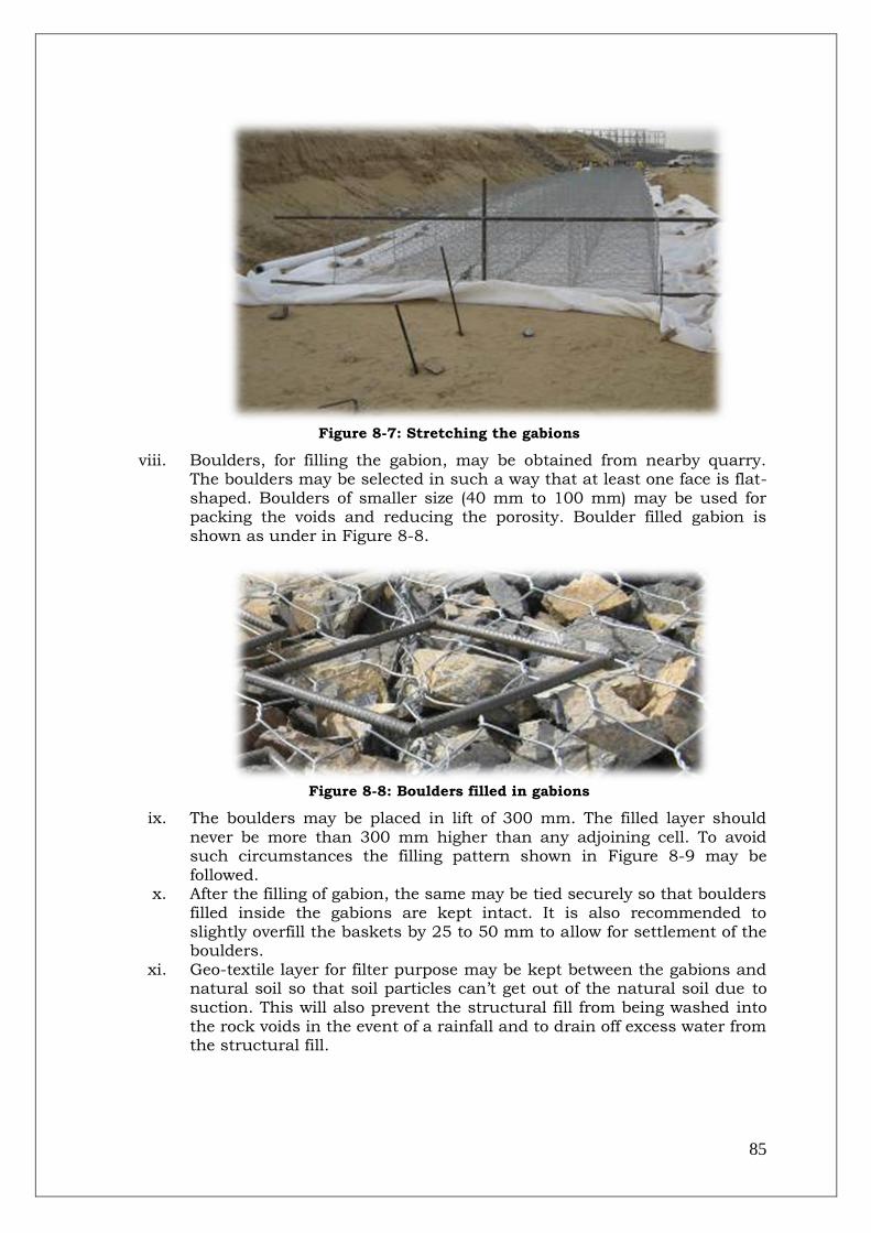
85
Figure 8-7: Stretching the gabions
viii. Boulders, for filling the gabion, may be obtained from nearby quarry. The boulders may be selected in such a way that at least one face is flat-shaped. Boulders of smaller size (40 mm to 100 mm) may be used for packing the voids and reducing the porosity. Boulder filled gabion is shown as under in Figure 8-8.
Figure 8-8: Boulders filled in gabions
ix. The boulders may be placed in lift of 300 mm. The filled layer should
never be more than 300 mm higher than any adjoining cell. To avoid such circumstances the filling pattern shown in Figure 8-9 may be followed.
x. After the filling of gabion, the same may be tied securely so that boulders filled inside the gabions are kept intact. It is also recommended to slightly overfill the baskets by 25 to 50 mm to allow for settlement of the boulders.
xi. Geo-textile layer for filter purpose may be kept between the gabions and natural soil so that soil particles can‟t get out of the natural soil due to suction. This will also prevent the structural fill from being washed into the rock voids in the event of a rainfall and to drain off excess water from the structural fill.
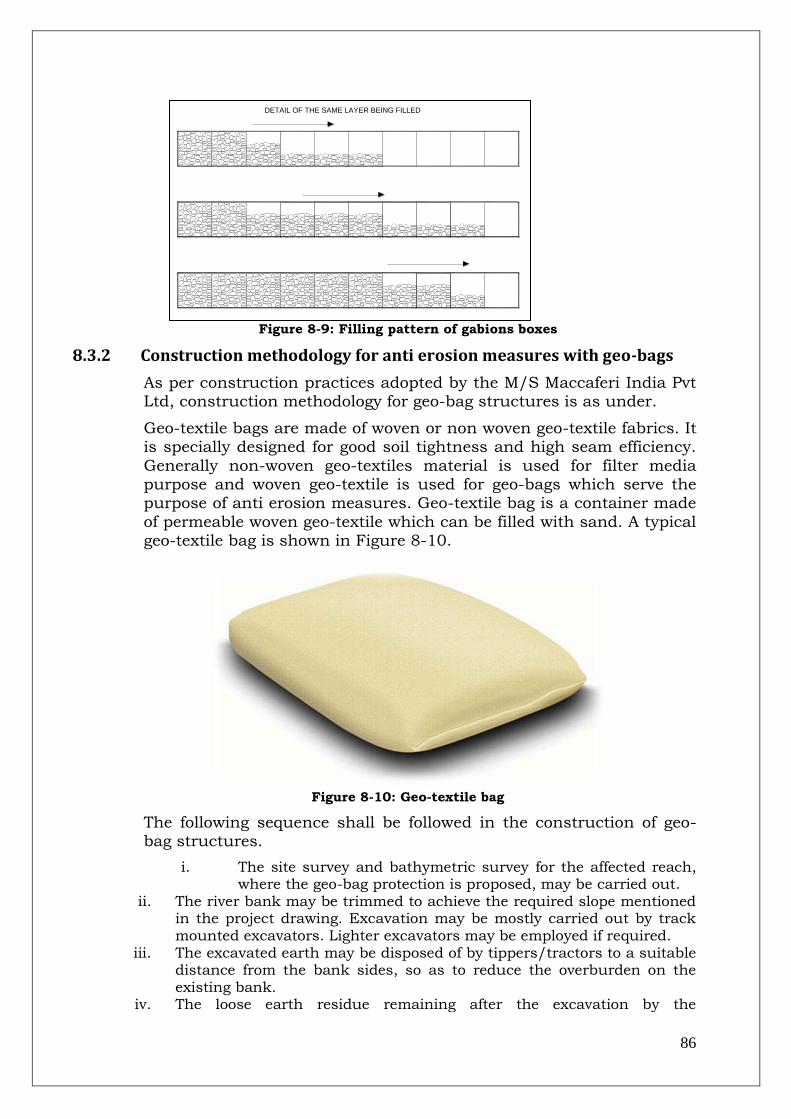
86
Figure 8-9: Filling pattern of gabions boxes
8.3.2 Construction methodology for anti erosion measures with geo-bags
As per construction practices adopted by the M/S Maccaferi India Pvt Ltd, construction methodology for geo-bag structures is as under.
Geo-textile bags are made of woven or non woven geo-textile fabrics. It is specially designed for good soil tightness and high seam efficiency.
Generally non-woven geo-textiles material is used for filter media purpose and woven geo-textile is used for geo-bags which serve the purpose of anti erosion measures. Geo-textile bag is a container made
of permeable woven geo-textile which can be filled with sand. A typical geo-textile bag is shown in Figure 8-10.
Figure 8-10: Geo-textile bag
The following sequence shall be followed in the construction of geo-bag structures.
i. The site survey and bathymetric survey for the affected reach, where the geo-bag protection is proposed, may be carried out.
ii. The river bank may be trimmed to achieve the required slope mentioned in the project drawing. Excavation may be mostly carried out by track mounted excavators. Lighter excavators may be employed if required.
iii. The excavated earth may be disposed of by tippers/tractors to a suitable distance from the bank sides, so as to reduce the overburden on the existing bank.
iv. The loose earth residue remaining after the excavation by the
DETAIL OF THE SAME LAYER BEING FILLED

87
machineries may be removed manually. The slope formation may be given necessary ramming to remove any undulations and corrected to the desired slope (if required) before the start of installation of the non woven geo-textile on the trimmed surface. At the bottom and top of the slope, anchor trench or key shall be prepared as per the required design.
v. The geo-textile fabric may be laid across the dressed slope over which sand filled geo-textile bags may be kept.
vi. The geo-textile may be filled at a location preferably higher than the HFL. This may ensure that the filling process of the bag remains unaffected by the rain and subsequent changes in the water levels.
vii. The sand used for filling may be transported to the site by dumpers and bulldozers or any other appropriate mode conducive to the local
availability and geographical suitability. The bags may be supplied to the project in the folded form and packed in bundles. The bags may be filled with sand by suitable methods. The sand used for filling should posses the technical specifications of the project. Filling of the sand bags is shown in Figure 8-11.
Figure 8-11: Filling of geo-bags
viii. After the sand filling is completed, the geo-textile bag may be weighed to confirm the desired weight as per the technical requirements of the project. After confirmation of the weight, the geo-textile bag may be stitched at the mouth by means of a bag closing machine as shown in the Figure 8-12.
Figure 8-12: Stitching of geo-textile bag

88
ix. For the sake of easy counting and monitoring the geo-textile bags may be stored in batches of 100 numbers or any suitable multiple as per the available space at site. The filled bags in group are shown in Figure 8-13.
Figure 8-13: Filled Geo-bags
x. The dumping of geo-bags for launching apron may be carried out using the motor boat/barge. The motor boat/barge may be positioned at the required location with the help of Total Station and anchored in position with the help of anchors. The dumping of the geo-textile bags shall be continued up to the location of the key at the bottom of the slope near LWL.
8.4 References Construction practices by Maccaferri India Pvt Limited.

89
9.0 Cost Estimate of Flood Management Works
9.1 General
Cost estimate is an integral part of any DPR. As usual cost estimate of any DPR of flood management project is based upon the rates and quantities of various items. The quantities of items are derived from the
design of the works. The rates of items are generally adopted from the Schedule of Rates of Engineering department of State and some times in the absence of particular rate in the Schedule of Rate, the same is
analyzed. The analysis of rate is dependent upon the location of site, basic item rates etc.
In this chapter, model cost estimate for various works like embankment, bank revetment, spur, RCC porcupine screens etc have been prepared on the basis of some assumptions and design using
provisions given in the various chapter of this handbook
9.2 Basic rates
Basic rates for items like labour rates, hire charges, material charges are given below in Table 9-1.
Table 9-1: Basic rates adopted for preparing indicative cost-estimate
# Item Rate (Rs.)
(A) Worker
1 skilled labour (for making wire cages etc) 157 per day
2 Semi-skilled labour (for turfing etc) 147 per day
3 Unskilled labour (Ordinary worker) 142 per day
(B) Materials
1 Diesel 42.35 per litre
2 Mobil 211 per litre
3 Cement 320 per bag
4 Sand 560 per m3
5 Coarse aggregate 1220 per m3
6 Steel 35 per kg
7 Timber pile(over-ground) 20 per m
8 Timber pile(under-ground) 25 per m
9 Geo bags of (1.07mx0.7mx0.15 m) 180 per bag
10 PVC pipe 15mm dia 50 per m
11 Polyethylene size 3mx 0.10m x 3.00m 4 per sq-m
12 Poly propylene gabion 1640 No
13 Geo tube of dia 2.5 m and length 25 m 3 lakh per tube
14 Geo-textile sheet as filter 122 sq-m
15 Wire netting sheet 559.3 per
sheet
16 wooden shuttering 200 sq-m
17 Steel Bolt 75 kg
(C) Hire Charges
1 Hire charge of truck 1500 per day
2 Mileage of truck 3 km/litre
3 Hire charge of barge 150 per hour
4 Hire charge of single engine boat of 10 tonne capacity 1200 per day
5 Hire charge for 20 Ton capacity mechanical crane 900 per hour

90
(D) Misc Items
1 Initial lead 5 km
2 Distance of project site from store 50 km
3 Forest Royalty sand 90 per m3
4 Forest Royalty boulder 130 per m3
5 Contractor's profit 20%
6 Labour welfare cess 1%
7 Vat 4%
8 Sundries (LS) 20
The quantities of the materials, labour, machinery etc in the estimation
of typical analysis of rates is based upon the various detailed project reports, prepared by the State Govt and “Estimation and Costing in
Civil Engineering” by B. N. Dutta.
9.3 Abstract of cost estimate of flood management works
Abstract of indicative cost estimate of various works is given below in table 9.2.
Table 9-2: Abstract of indicative cost-estimate
# Item Rate (Rs. Crore)
1 Cost of construction of earthen-embankment /km length 2.59
2 Cost of construction of geo-tube embankment (1 over 2 Geo-
tubes of 2.5 m dia) /km length
6.20
3 Cost of construction of bank pitching using boulders/km length 6.71
4 Cost of construction of bank pitching using geo bags /km length 8.58
5 Cost of construction of 1 boulder spur with 500 m shank length 2.51
6 Cost of construction of 1 geo-bag spur with 500 m shank length 2.79
7 Cost of bank protection using RCC porcupines /km length 1.17
9.4 Assumptions for cost estimate These rates are purely indicative and would vary as per site conditions and
specific design adopted for the works.
These costs are construction costs and are different from economic cost which includes maintenance cost, depreciation, interest etc.
Height of embankment/spur as been adopted as 5 m.
Slope length of the river bank is taken as 15 m.
Distance of boulder quarry from the site is 25 km.
Lead for the collection of sand is 5 km.
Length of earthen shank for spur is 500 m.
There is provision of 25 m pitching at the river bank each at u/s and d/s of the spur.
RCC porcupines are provided in 8 rows along the bank and spurs of length 50 m across the bank @ 100 m c/c.
9.5 Cost of construction of earthen-embankment/km length
Design Assumptions:
Length of embankment = 1000 m
Top width = 5 m
R/S slope = 2 :1
C/S slope = 3 :1
Average height of embankment = 5 m
Considering above assumptions
Base width = 30 m
Average cross sectional area = 87.5 m2

91
R/S slope length = 11.2 m
C/S slope length = 15.8 m
Total length of pile , assuming 4 piles @ 25 m c/c 3 m above the ground, for
profiling
= 492 m
Total length of pile , assuming 4 piles @
25 m c/c 2 m below the ground, for
profiling
= 328 m
Estimate:
Item of Work Quantity Unit Rate
(Rs.)
Amount
(Rs.)
1
Supplying and driving timber pile (25 to
30 cm dia) including marking the length
(coaltaring 2 coats)
a. Portion of pile driven above ground (rates as given in table 9.1)
492 m 20 9,840
b: Portion of pile underground (rates as
given in table 9.1)
328 m 25 8,200
2 Earth work in grabbing the seat (0.45 m
deep trench) of the embankment by
removing the sludges/ undesirable, foreign materials and refilling the same
with selected soil (1000*30*.45). (rates as
per analysis no. 9.12.1)
13,500 m3 58.31 7,87,136
3 Earth work in embankment by truck
carriage in all kinds of soils excluding sandy rocky soil free from roots and
vegetation and filling in uniform layers not
exceeding 22.50 cm thick including
cutting and clearing light jungles and
trees any etc. .(1000*87.5) (rates as per
analysis no. 10.1.2).
87,500 m3 275.11 2,40,72,157
4 Turfing with grass sods of largest possible
rectangle of 12 mm thickness placed
closely including dressing earth, pegging,
ramming and watering till the grass grows
for a lead upto 90 m and all lifts complete as directed on both slopes
(1000*(11.2+15.8)) (rates as per analysis
no.10.1.3)
26,992 m2 8.11 2,18,792
5 Collection and supply of boulders/gravel
from approved quarry free from dust dirt
and any foreign materials (1000*5*0.15) (rates as per analysis no. 10.1.6).
750 m3 537.75 4,03,310
6 Spreading of earth stack over the crest
and in uniform layers not exceeding 30
cm thick (1000*0.15*5) (rates as per
analysis no. 10.1.4)
750 m3 45.98 34,486
Total 2,55,33,921
Add 1.5% contingency 3,83,009
Grand Total Rs 2,59,16,930

92
9.6 Cost of construction of geo-tube-embankment/km length
Design Assumptions:
Length of embankment = 1000 m
Top width = 5 m
R/S slope = 2 :1
C/S slope = 3 :1
Average height of embankment = 5 m
Considering above assumptions
Base width = 30 m
Average cross sectional area = 87.5 m2
R/S slope length = 11.2 m
C/S slope length = 15.8 m
Considering 1 over 2 Geo tubes of dia 2.5
m and length 25 m as core of the embankment, nos of geo tubes
= 120 Nos
Volume of slurry in one geo tube = 123 m3
Total length of pile , assuming 4 piles @
25 m c/c 3 m above the ground, for
profiling
= 492 m
Total length of pile , assuming 4 piles @ 25 m c/c 2 m below the ground, for
profiling
= 328 m
Estimate:
Item of Work Quantity Unit Rate
(Rs.)
Amount
(Rs.)
1 Earth work in grabbing the seat (0.45 m deep trench) of the embankment by
removing the sludges/ undesirable,
foreign materials and refilling the same
with selected soil (1000*30*.45). (rates as
per analysis no. 10.1.1)
13,500 m3 58.31 7,87,136
2 Earth work in embankment by truck
carriage in all kinds of soils excluding
sandy rocky soil free from roots and
vegetation and filling in uniform layers not
exceeding 22.50 cm thick including
cutting and clearing light jungles and trees any etc. .(1000*87.5) (rates as per
analysis no. 10.1.2).
72,768 m3 275.11 2,00,19,192
3 Supply and transportation of geo-tube
with requisite qualities
120 Nos 3,00,000 3,60,00,000
4 Filling and laying of geo-tubes 14,732 m3 246 3,6,24,107
5 Turfing with grass sods of largest possible rectangle of 12 mm thickness placed
closely including dressing earth, pegging,
ramming and watering till the grass grows
for a lead upto 90 m and all lifts complete
as directed on both slopes (1000*(11.2+15.8)) (rates as per analysis
no. 10.1.3)
26,992 m2 8.11 2,18,792
6 Collection and supply of boulders/gravel
from approved quarry free from dust dirt
and any foreign materials (1000*5*0.15)
(rates as per analysis no. 10.1.6).
750 m3 537.75 4,03,310
7 Spreading of earth stack over the crest
and in uniform layers not exceeding 30
cm thick (1000*0.15*5) (rates as per
750 m3 45.98 34,486

93
analysis no. 10.1.4)
Total 6,10,87,023
Add 1.5% contingency 9,16,305 Grand Total Rs 6,20,03,328

94
9.7 Construction of bank pitching in boulders
Design Assumptions (pitching in loose and apron in wire crates):
Length of bank protection = 1000 m
Slope length = 15 m
Thickness of pitching (2 layers of 0.30 m
thick) = 0.6 m
Quantity of boulders in pitching = 9000 m3
Width of launching apron (in crates) = 24 m
Thickness of launching apron (in crates) = 0.9 m
Quantity of boulders in crates for
launching apron = 21600 m3
Nos of wire crates for boulders in crates
(2 nos of crates per m3) 43200 nos
quantity of Non-woven geo-textile fabric sheet for slope protection
= 17000 m2
Estimate:
Item of Work Quantity Unit Rate
(Rs.)
Amount
(Rs.)
1 Earthwork in bank trimming to the
designed section/ slope including removing the spoils and depositing in
bank of the river (rates as per analysis
no. 10.1.5).
2250 m3 71.10 1,59,972
2 Collection and supply of boulders/gravel
from approved quarry free from dust dirt
and any foreign materials (rates as per analysis no. 10.1.6).
30,600 m3 537.75 1,64,55,061
3 Local carriage of boulder from the
approachable site beyond 150 m from
the work site with 10 (ten) ton capacity
truck, (lead taking as 25 km) (rates as per analysis no. 10.1.7).
30,600 m3 474.42 1,45,17,150
4 Preparation of stack-yard for boulder/
metal/ boulder (rates as per analysis no.
10.1.8).
30,600 m3 9.47 2,89,802
5 Supply of Non-woven Geo-textile fabric sheet of 400 gsm including for laying
and stitching (1 m extra on top and toe
for anchoring purpose) (rates as given in
table 9.1)
17,000 m2 122 20,74,000
6 Supply of galvanized wire netting sheet
made of 8g wire 152mm (6") square mesh in sheet 2.57m x 1.66m with
longitudinal wire at 152mm center at
76mm projection of each wire on all side
beyond net size of 2.42 m x 1.51 m
having knots at every joint including loading, unloading, stacking complete as
directed. (Weight of each sheet should
not be less than 6.3 kg / sheet.)
43,200 nos 559.3 2,41,61,760
7 Local carriage of galvanized. wire netting
sheets by truck (rates as per analysis no.
10.1.9).
43,200 nos 6.70 2,89,399
8 Labour charge for dumping boulder in
cage made of wire netting sheets (Rates
21,600 nos 295.38 63,80,294

95
Analysis No. 10.1.10)
9 Labour charge for laying and pitching
(rates as per analysis no. 10.1.11)
9,000 m2 199.18 17,92,620
Total 6,61,20,058
Add 1.5% contingency 9,91,801
Grand Total Rs 6,71,11,859

96
9.8 Construction of bank pitching in geo bags
Design Assumptions (pitching in loose and apron in gabions):
Length of bank protection = 1000 m
Slope length = 15 m
Thickness of pitching (2 layers of 0.30 m
thick) = 0.6 m
No. of layers of geo bag of size
(1.03mx0.70 mx0.15m) for pitching
= 4 nos
Nos of geo bags for pitching = 83218 nos
Thickness of launching apron (in crates) = 0.9 m
Width of launching apron = 24 m
Thickness of launching apron = 0.9 m
Nos of geo bags in one gabion of size
(2mx2mx0.9 m) = 18 nos
Nos of gabions for launching apron = 12000 nos
Nos of geo bags (filled in gabions) in
launching apron
= 216000 nos
Estimate:
Item of Work Quantity Unit Rate
(Rs.)
Amount
(Rs.)
1 Earthwork in bank trimming to the
designed section/ slope including
removing the spoils and depositing in
bank of the river (rates as per analysis
no. 10.1.5).
2250 m3 71.10 1,59,972
2 Supply of geo- bags of size 1.03mx0.70mx 0.15 m (Rates as per
given in table 9.1)
2,99,218 nos 180.00 5,38,59,196
3 Carriage of geo bags from Godown to
different work sites (rates as per analysis
no. 10.1.12).
2,99,218 nos 3.00 8,96,865
4 Supply of poly propylene (PP) gabions of
size 2mx2mx0.90 m (rates as given in
table 9.1)
12,000 nos 1640 1,96,80,000
5 Carriage of gabions from Godown to
different work sites (rates as per analysis
no. 10.1.13).
12,000 nos 6.17 74,050
6 Filling of Geo-bags of size 1.03mx0.70 m
and bank pitching (rates as per analysis
no. 10.1.14)
83,218 nos 30.06 25,01,664
7 Dumping of sand filled geo bags
contained in gabions from properly
positioned and anchored flat top pontoon/barge (rates as per analysis no.
10.1.15)
12,000 nos 613.81 73,65,696
Total 8,45,37,442
Add 1.5% contingency 12,68,062
Grand Total 8,58,05,504

97
9.9 Construction of boulder spur with earthen shank
Design Assumptions (pitching in loose and apron in wire crates)
A Shank portion tie with embankment
Length of earthen shank = 500 m
Top width = 3 m
R/S slope = 2 :1
C/S slope = 2 :1
Average height of shank = 5 m
Considering above assumptions
Base width = 23 m
Average cross sectional area = 65 m2
R/S slope length = 11.18 m
C/S slope length = 11.18 m
B
Length of bank protection (25 m u/s and
d/s of the spur) to avoid outflanking = 50 m
Slope length = 15 m
Thickness of pitching (2 layers of 0.30 m
thick) = 0.6 m
Quantity of boulders in pitching = 450 m3
Width of launching apron (in crates) = 24 m
Thickness of launching apron (in crates) = 0.9 m
Quantity of boulders in crates for
launching apron = 1080 m3
Nos of wire crates for boulders in crates (2 nos of crates per m3)
2160 nos
C Nose of spur with shank pitching
Top width
3 m
Side slope
2 :1
Height of spur
5 m
Considering above assumptions
Base width = 23 m
Average cross sectional area = 65 m2
slope length = 11.18 m
Thickness of pitching (2 layers of 0.30 m
thick) = 0.6 m
Length of pitching at nose = 4.7143 m
Length of pitching at shank in U/S
(30+30+30) = 90 m
Length of pitching at shank in D/S
(30+15)
= 45 m
Quantity of boulders in pitching = 937.2 m3
Width of Launching Apron at nose = 34.5 m
Width of Launching Apron for transition
from nose to shank and up to 30 m U/S
= 24 m
Width of Launching Apron for next 30 m
in U/S
= 9 m
Width of Launching Apron for transition
from nose to shank and 1st 15 m D/S
= 9 m
Thickness of launching apron (in crates) = 0.9 m
Quantity of boulder in nose portion = 1683.4 m3
Quantity boulder for Launching Apron
for transition from nose to shank and up to 30 m U/S
= 1437.8 m3
Quantity of boulder for Launching Apron
for next 30 m in U/S
= 648 m3
Quantity of boulder for Launching Apron
for transition from nose to shank and 1st 15 m D/S
= 708.75 m3

98
Total quantity of boulder in apron = 4478 m3
Nos of wire crates for boulders in crates
(2 nos of crates per m3)
= 8956 nos
Estimate:
Item of Work Quantity Unit Rate
(Rs.)
Amount
(Rs.)
1
Supplying and driving timber pile (25 to
30 cm dia) including marking the length
(coaltaring 2 coats)
a. Portion of pile driven above ground (Rates as per given in table 9.1)
252 m 20 5,040
b: Portion of pile underground (Rates as
per given in table 9.1)
168 m 25 4,200
2 Earth work in grabbing the seat (0.45 m
deep trench) of the embankment by removing the sludges/ undesirable,
foreign materials and refilling the same
with selected soil (500*23*0.45). (Rates
as per Analysis no. 10.1.1)
5,175 m3 58.31 3,01,736
3 Earth work in embankment by truck
carriage in all kinds of soils excluding sandy rocky soil free from roots and
vegetation and filling in uniform layers
not exceeding 22.50 cm thick including
cutting and clearing light jungles and
trees any etc. (500*65) (Rates as per Analysis no. 10.1.2).
32,500 nos 275.11 89,41,087
4 Turfing with grass sods of largest
possible rectangle of 12 mm thickness
placed closely including dressing earth,
pegging, ramming and watering till the
grass grows for a lead upto 90 m and all lifts complete as directed on both slopes
(500*(11.18+11.18)) (Rates as per
Analysis No.10.1.3)
8,162 m2 8.11 66,158
5 Collection and supply of boulders/gravel
from approved quarry free from dust dirt and any foreign materials (500*3*0.15)
(Rates as per Analysis No. 10.1.6).
225 m3 537.75 1,20,993
7 Spreading of earth stack over the crest
and in uniform layers not exceeding 30
cm thick (500*0.15*3) (Rates as per
analysis No. 10.1.4)
225 m3 45.98 10,346
Total
94,49,560
B
Length of bank protection (25 m u/s
and d/s of the spur) to avoid
outflanking
1 Earthwork in bank trimming to the
designed section/ slope including
removing the spoils and depositing in
bank of the river (rate as per analysis no.
10.1.5).
113 m3 71.10 7,999
2 Collection and supply of boulders/gravel from approved quarry free from dust dirt
and any foreign materials (rate as per
analysis no. 10.1.6).
1,530 m3 537.75 8,22,753
3 Local carriage of boulder from the 1,530 m3 474.42 7,25,858

99
approachable site beyond 150 m from
the work site with 10 (ten) ton capacity
truck, (lead taking as 25 km) (rate as per analysis No. 10.1.7).
4 Preparation of stack-yard for boulder/
metal/ boulder (Rate as per analysis
10.1.8).
1,530 m3 9.47 14,490
5 Supply of non-woven geo-textile fabric
sheet of 400 gsm including for laying and stitching (1 m extra on top and toe
for anchoring purpose) (rates as given in
table 9.1)
850 m2 122 1,03,700
6 Supply of galvanized wire netting sheet
made of 8g wire 152mm (6") square mesh in sheet 2.57m x 1.66m with
longitudinal wire at 152mm center at
76mm projection of each wire on all side
beyond net size of 2.42 m x 1.51 m
having knots at every joints including
loading, unloading, stacking complete as directed. (Weight of each sheet should
not be less than 6.3 kg / sheet) (rates as
given in table 9.1)
2,160 nos 559.3 12,08,088
7 Local carriage of galvanized wire netting
sheets by truck (rates as per analysis no. 10.1.9).
2,160 nos 6.70 14,470
8 Labour charge for dumping boulder in
cage made of wire netting sheets (rates
as per analysis no. 10.1.10)
1,080 m3 295.38 3,19,015
9 Labour charge for laying and pitching
(rates as per analysis no. 10.1.11)
450 m2 199.18 89,631
Total(50 m pitching)
33,06,004
C Nose of spur with shank pitching
1 Collection and supply of boulders/gravel
from approved quarry free from dust dirt and any foreign materials (rate as per
analysis no. 10.1.6).
5,415 m3 537.75 29,11,946
2 Local carriage of boulder from the
approachable site beyond 150 m from
the work site with 10 (ten) ton capacity
truck, (lead taking as 25 km) (rate as per analysis No. 10.1.7).
5,415 m3 474.42 25,69,007
3 Preparation of stack-yard for boulder/
metal/ boulder (Rate as per analysis
10.1.8).
5,415 m3 9.47 51,284
4 Supply of Non-woven Geo-textile fabric sheet of 400 gsm including for laying
and stitching (1 m extra on top and toe
for anchoring purpose) (Rates as per
given in table 9.1)
1,841 m2 122 2,24,661
5 Supply of galvanized wire netting sheet
made of 8g wire 152mm (6") square mesh in sheet 2.57m x 1.66m with
longitudinal wire at 152mm center at
76mm projection of each wire on all side
beyond net size of 2.42 m x 1.51 m
having knots at every joints including
loading, unloading, stacking complete as
8,956 nos 559.30 50,08,927

100
directed. (Weight of each sheet should
not be less than 6.3 kg / sheet.) (Rates
as per given in table 9.1) 6 Local carriage of galvanized wire netting
sheets by truck (Rate as per Analysis
10.1.9)
8,956 nos 6.70 59,995
7 Labour charge for dumping boulder in
cage made of wire netting sheets (With
boat) (Rate Analysis No. 10.1.10)
1,683 m3 295.38 4,97,236
8 Labour charge for dumping boulder in
cage made of wire netting sheets
(Without boat) (Rates Analysis No.
10.1.16)
2,795 m3 164.58 4,59,930
9 Labour charge for laying and pitching (Rate as per Analysis 10.1.11)
937 m2 199.18 1,86,678
Total (Nose of spur with shank pitching) 1,19,69,665
Total cost of boulder spur
2,47,25,228
Add 1.5% contingency
3,70,878
Grand Total
2,50,96,107

101
9.10 Construction of spur with geo-bags with earthen shank Design Assumptions: (pitching in bags and apron in gabions) A Shank portion tie with embankment
Length of earthen shank = 500 m
Top width = 3 m
R/S slope = 2 :1
C/S slope = 2 :1
Average height of shank = 5 m
Considering above assumptions
Base width = 23 m
Average cross sectional area = 65 m2
R/S slope length = 11.18 m
C/S slope length = 11.18 m
B Length of bank protection (25 m u/s and
d/s of the spur) to avoid outflanking = 50 m
Slope length = 15 m
Thickness of pitching (4 layers of 0.15 m
thick geo bags) = 0.6 m
No. of layers of geo bag of size
(1.03mx0.70 mx0.15m) for pitching
= 4 nos
Nos of geo bags for pitching = 4161 nos
Width of launching apron = 24 m
Thickness of launching apron = 0.9 m
No.s of geo bags in one gabion of size (2mx2mx0.9 m)
= 18 nos
Nos of gabions for launching apron
600 nos C
Nos of geo bags (filled in gabions) in
launching apron = 10800 nos
C Nose of spur with shank pitching
Top width = 3 m
Side slope = 2 :1
Height of spur = 5 m
Considering above assumptions
Base width = 23 m
Average cross sectional area = 65 m
slope length = 11.18 m
Thickness of pitching (4 layers of 0.15 m
thick geo bags) = 0.6 m
Length of pitching at nose = 4.7143 m
Length of pitching at shank in U/S (30+30+30)
= 90 m
Length of pitching at shank in D/S
(30+15)
= 45 m
Quantity of geo-bags in pitching = 746 nos
Width of Launching Apron at nose = 34 m
Width of Launching Apron for transition from nose to shank and up to 30 m U/S
= 24 m
Width of Launching Apron for next 30 m
in U/S
= 10 m
Width of Launching Apron for transition
from nose to shank and 1st 15 m D/S
= 10 m
Thickness of launching apron (in crates) = 0.9 m
No. of gabions in nose portion = 908 nos
No. of gabions for Launching Apron for
transition from nose to shank and up to
30 m U/S
= 795 nos
No. of gabions for Launching Apron for next 30 m in U/S
= 360 nos

102
No. of gabions for Launching Apron for
transition from nose to shank and 1st 15
m D/S
= 405 nos
Total quantity of gabions in apron = 2468 nos
Nos of bags in gabions for launching
apron (18 bags per gabion) = 44424 nos
Estimate:
Item of Work Quantity Unit Rate
(Rs.) Amount
(Rs.)
1
Supplying and driving timber pile (25 to
30 cm dia) including marking the length
(coaltaring 2 coats)
a. Portion of pile driven above ground
(Rates as per given in table 9.1)
252 m 20 5,040
b: Portion of pile under ground (Rate as per given in table 9.1)
168 m 25 4,200
2 Earth work in grabbing the seat (0.45 m
deep trench) of the embankment by
removing the sludges/undesirable,
foreign materials and refilling the same with selected soil (500*23*0.45). (Rates
as per Analysis no. 10.1.1)
5,175 m3 58.31 3,01,736
3 Earth work in embankment by truck
carriage in all kinds of soils excluding
sandy rocky soil free from roots and
vegetation and filling in uniform layers not exceeding 22.50 cm thick including
cutting and clearing light jungles and
trees any etc. (500*65) (rates as per
analysis no. 10.1.2).
32,500 nos 275.11 89,41,087
4 Turfing with grass sods of largest possible rectangle of 12 mm thickness
placed closely including dressing earth,
pegging, ramming and watering till the
grass grows for a lead upto 90 m and all
lifts complete as directed on both slopes
(500*(11.18+11.18)) (rates as per analysis no. 10.1.3)
8,162 m2 8.11 66,158
5 Collection and supply of boulders/gravel
from approved quarry free from dust dirt
and any foreign materials (500*3*0.15)
(Rates as per Analysis No. 10.1.6).
225 m3 537.75 1,20,993
7 Spreading of earth stack over the crest
and in uniform layers not exceeding 30
cm thick (500*0.15*3) (rates as per
analysis no. 10.1.4)
225 m3 45.98 10,346
Total 94,49,560
B
Length of bank protection (25 m u/s
and d/s of the spur) to avoid outflanking
1 Earthwork in bank trimming to the
designed section/ slope including
removing the spoils and depositing in
bank of the river (rates as per analysis no. 10.1.5).
113 m3 71.10 7,999
2 Supply of Geo- bags of size
1.03mx0.70mx 0.15 m(Rates as per
given in table 9.1)
14961 nos 180.00 26,92,960

103
3 Carriage of geo bags from Godown to
different work site(rates as per analysis
no. 10.1.12).
14,961 m3 3.00 44,843
4 Supply of poly propylene (PP) gabions of
size 2mx2mx0.90 m(rates as given in
table 9.1)
600 m3 1460 9,84,000
5 Carriage of gabions from Godown to
different work site (rates as per analysis
no. 10.1.13).
600 m2 6.17 3,702
6 Filling of Geo-bags of size 1.03mx0.70 m
and bank pitching (Rates as per Analysis
No. 10.1.14)
4,161 nos 30.06 1,25,083
7 Dumping of sand filled Geo bags
contained in gabions from properly positioned and anchored flat top
pontoon/barge (rates as per analysis no.
10.1.15)
600 nos 613.81 3,68,285
Total(50 m pitching)
42,26,872
C Nose of spur with shank pitching 1 Supply of Geo- bags of size
1.03mx0.70mx0.15 m(rates as given in
table 9.1)
45,170 m3 180 81,30,625
2 Carriage of geo bags from Divisional
Godown to different work site (rates as per analysis no. 10.1.12).
45,170 m3 3.00 1,35,391
3 Supply of poly propylene (PP) gabions of
size 2mx2mx0.90 m(Rates as per given
in table 9.1)
2,468 m3 1640 40,47,520
4 Carriage of gabions from Divisional
Godown to different work site(rates as per analysis no. 10.1.13).
2,468 m2 6.17 15,230
5 Filling of Geo-bags of size 1.03mx0.70 m
and bank pitching (rates as per analysis
no. 10.1.14)
746 nos 30.06 22,430
6 Dumping of sand filled Geo bags contained in gabions from hydraulic
crane (rates as per analysis no. 10.1.17)
1,560 nos 542.38 8,46,119
7 Dumping of sand filled Geo bags
contained in gabions from properly
positioned and anchored flat top
pontoon/barge (rates as per analysis no. 10.1.15)
908 nos 613.81 5,57,338
Total (Nose of spur with shank pitching) 1,37,54,653
Total cost of geo-bag spur
2,74,31,085
Add 1.5% contingency
4,11,466
Grand Total
2,78,42,552

104
9.11 Construction of bank protection using RCC porcupines
Design Assumptions:
A Length of bank protection = 1000 m
Slope length = 15 m
Nos of porcupines with provision of 5
rows of RCC porcupines @ 3 m c/c (2
above the toe line and 3 below the toe
line) along the river bank
= 1452 nos
Nos of porcupines with provision of RCC
porcupine spurs (comprising of 5 rows @
3 m c/c) of length 50 m @ 100 m c/c
across river bank
= 972 nos
Total nos of RCC porcupines = 2424 nos
RCC porcupines to be laid without boat
581 nos
RCC porcupines to be laid with boat
1843 nos
Estimate:
Item of Work Quantity Unit Rate
(Rs.)
Amount(Rs
.)
1 Earthwork in bank trimming to the
designed section/ slope including
removing the spoils and depositing in bank of the river (rate as per analysis no.
10.1.5).
2,250 m3 71.10 1,59,972
2 Construction of R.C.C. porcupine
comprising members of size 0.1 x 0.1 x
3.0m in proportion 1:2:4 (1 cement, 2 coarse sand, 4 graded stone aggregate
20mm down) including fitting fixing 4
nos. of 8mm dia. Plain mild steel rods &
6mm dia. Stirrups @ 18 cm c/c tied with
20 G annealed black wire including
curing etc. complete as directed (Rates as per Analysis No. 10.1.18).
2,424 nos 4,430.64 1,07,39,870
3
Local carriage of RCC member of size
3.00M x 0.10M x 0.10M from stockyard
but not more than 4 km including
loading and unloading etc. complete. (Rates as per Analysis No. 10.1.19).
2,424 nos 66.99 1,62,385
4
Assembling and placing of RCC
porcupines in position at river bed,
slope, dry river bed, (Rates as per
Analysis No. 10.1.20).
581 nos 186.64 1,08,373
5
Assembling (on twin-boat/flat board barge) RCC porcupines made of 6 (six)
Nos. .((Rates as per Analysis No.
10.1.21).
1,843 nos 197.24 3,63,572
Total
1,15,34,172
Add 1.5% contingency
1,73,013
Grand total Rs 1,17,07,1855
9.12 References 1. “Estimation and Costing in Civil Engineering” by B. N. Dutta
2. Detailed project reports for flood management works by Govt of Assam

105
10.0 Unit Rate Analysis for Flood Management Works
10.1 General
Rate Analysis of various items taken into account for cost estimate of
flood management works mentioned in section 9 are given as under.
10.1.1 Earth in excavation
Analysis of rate no.10.1.1
Earthwork in excavation in branches in channel dredging/cutting in all kinds of soil
including rock soil upto a depth of 2.0 to 2.50 m from the existing bed level carrying
and depositing the entrusted.
Volume of Earth 100 m3
Item
No.
Description Rate
(Rs)
Quantity Amount
(Rs.)
A Material B Worker (33 Nos. for 100 m3 earthwork)
(i) Ordinary labour for excavation in branches as per
design specification and deposit of the land for lead
upto 30 m and lift upto 4.5 m including removal of
foreign materials , dressing , and profiling ,
breaking plots etc.
142.00 33 4,686.00
Sub-total 4,686.00
C Sundries (LS)
20.00
D Add 20% contractor's profit (On Sub-total) 937.20
E VAT 4% on sub-total
187.44
Total
5,830.64 Hence, Rate per m3 =Rs 58.31

106
10.1.2 Earthwork in embankment filling
Analysis of rate no.10.1.2
Earth work in embankment by truck carriage in all kinds of soils excluding rocky soil
free from roots and vegetation and filling in uniform layers not exceeding 22.50 cm thick including cutting and clearing light jungles and trees upto 50 cm girth ploughing
breaking clods upto 25mm cube dressing as per design section including payment of
forest royalty (10% deduction may be made from section measurement after
completion on account of shrinkages.)
For initial lead up to 5 km
Total distance from quarry site to construction site in six trips (2*5*6)
= 60 km
Considering one (10 ton capacity) diesel truck can
carry 5.00 m3 and make 6 trips per day in 8
(Eight) working hours.
Total quantity of earth carried by the truck in 8 hours (5*6)
= 30 m3
Deduction of 10% on account of shrinkages = 3 m3
Net quantity of earth carried by the truck in 8
hours
= 27 m3
Item No.
Description Rate (Rs)
Quantity Amount (Rs.)
A Material
(i) Hire charge of diesel truck of 10 ton capacity
including wages of driver and handyman for 8
hours only.
1,500 1 1,500.00
(ii) Diesel required (Up & down)
@ 3.00km/ltr = 60/3 = 20 liters
42.35 20 847.00
(iii) Mobil 0.5 Ltr. 211 0.5 105.50
B Workers (33 for 100 m3 of earth)
(i) Ordinary labour for excavation 142.00 5 710.00
(ii) Ordinary labour for loading and unloading 142.00 5 710.00 (iii) Ordinary labour for removing jungles and breaking
clods dressing etc. including ramming and
watering and consolidation
142.00 1 142.00
Sub total 4,014.50
C Compensation of earth/forest royalty etc. @Rs.90/cum
90 27 2,430.00
D Sundries 20.00
E Add 20% contractors profit (on sub-total) 802.90
F VAT 4%(on sub-total) 160.58
Total 7,427.98
Hence, Rate per m3 =Rs 275.11

107
10.1.3 Turfing
Analysis of rate no.10.1.3
Turfing with grass sods of 12 cm minimum thickness placed closely together including
dressing earth, pegging, ramming and watering till the grass grows for lead upto 90 m and all lifts.
Area of turfing work from a lead of 90.00 M = 100 m2
Item
No.
Description Rate
(Rs)
Quantity Amount
(Rs.)
A Materials
(i) Jati bamboo (for pegging) 37.00 0.25 9.25
B Workers (i) Semi-skilled labour required for cutting the turfing
in proper size and Thickness 147.00 1 147.00
(ii) Semi-skilled labour for carrying of turfing and
laying in proper place as per specification in item
of work etc
147.00 3 441.00
Sub-Total
597.25
C Compensation for borrowing turfing from private
land
50.00 1 50.00
D Sundries(LS)
20.00
E Add 20% contractors profit (on sub-total)
119.45
F VAT 4%(on sub-total)
23.89 Total 810.59
Hence, Rate per m2 =Rs 8.11

108
10.1.4 Spreading of earth over crest Analysis of rate no.10.1.4
Spreading of earth stack over the crest of the embankment, stack-yard in uniform
layers not exceeding 30 cm thick including dressing, ramming etc. with local carriage up to 150 m.
Volume of earth = 100 m3
Item
No.
Description Rate
(Rs)
Quantity Amount
(Rs.)
A Materials
B Workers (20 nos for 100 m3)
(i) Ordinary Labour 142.00 20 2840.0 (ii) Ordinary Labour for watering 142.00 2 284.00
(iii) Ordinary Labour for ramming the earth etc. 142.00 4 568.00
Sub-Total 3692.0
2 Sundries (LS) 20.00
4 Add 20% contractor's profit (On Sub-total) 738.40 6 VAT 4% on sub-total 147.68
Total 4,598.08
Hence, Rate per m3 =Rs 45.98

109
10.1.5 Earthwork in bank trimming Analysis of rate no.10.1.5
Earthwork in bank trimming to the designed slope including removing and depositing
the spoils at place(s) as or all leads and lifts.
Considering area of earth work in trimming = 30 m2
Item
No.
Description Rate
(Rs)
Quantity Amount
(Rs.)
A Materials NIL
Nil
B Workers
(I) Ordinary workers for excavation of earthwork in bank trimming to designed slope
3 142 426.00
(II) Ordinary worker for carrying earth and depositing
at places as directed
8 142 1136.0
(III) Ordinary worker for clearance 1 142 142.00
Sub total 1704.0 C Sundries (LS) 20.00
D Add 20% contractors profit (on sub-total) 340.80
E VAT 4%(on sub-total) 68.16
Total 2,132.96
Hence, Rate per m2 =Rs 71.10

110
10.1.6 Collection of boulders Analysis of rate no.10.1.6
Collection of boulder of size 23 cm to 30 cm (man size) free from all foreign impurities
and debris, hammering to proper size and stacking properly at quarry including payment of forest royalty. VAT etc.
Volume of boulders = 28.3 m3
Item No.
Description Rate (Rs)
Quantity Amount (Rs.)
A Materials
Gelatin 112 3.88 kg 434.56
Detonator 3.92 50 Nos 196
Total (Materials) 630.56
B Workers Skilled labour 157 1 142.00
Driller (as equivalent to skilled labour) 157 40 1,704.00
C Blast-man 200 1.5 20.00
D Hammer-man for breaking the blasted boulder 142 12 340.80
E Labour for stacking the boulder 142 6 68.16
Sub-total 9,223.00 C Sundries 20
D Forest Royalty (Rs 130/m3) 130 28.3 3,680.3
E Contractor‟s profit ( 20% on sub-total) 1,858.
VAT 4% on sub-total 6,371.70
Total 15,223.62 Hence, Rate per m3 =Rs 537.75

111
10.1.7 Local carriage of boulders Analysis of rate no.10.1.7
Local carriage of boulder from the quarry site beyond 150 m from the work site with 10
ton capacity truck.
Lead = 25 km
Total distance from quarry site to construction site
in three trips (2*25*3)
= 150 km
Considering one (10 ton capacity) diesel truck can
carry 4.00 M3 and make 3 trips per day in 8 (Eight) working hours.
Total quantity of boulders carried by the truck in 8
hours (4*2)
= 12 m3
Item
No.
Description Rate
(Rs)
Quantity Amount
(Rs.)
A Materials
(i) Hire charge of diesel truck including wages of driver and handyman
1,500 1 1,500.00
(ii) Diesel required (Up & down)
@ 3.00km/ltr = 200/3
42.35 50 2,117.50
(iii) Mobil 211 0.5 105.50
B Workers
(i) Ordinary labour for loading and unloading 142 6 852.00 Sub-Total 4575.00
C Sundries(LS) 20.00
D Contractor‟s profit ( 20% on sub-total) 915.00
E VAT 4%(sub-total) 183.00
Total 5693.00 Hence, Rate per m3
=Rs 474.42

112
10.1.8 Preparation of stack-yard Analysis of rate no.10.1.8
Local carriage of boulder from the quarry site beyond 150 m from the work site with 10
ton capacity truck.
Consider surface area = 30 m2
Item
No.
Description Rate
(Rs)
Quantity Amount
(Rs.)
A Materials NIL
Nil
B Workers
(I) One Ordinary labour can clear 30 m² of light jungle and trees etc. in one day (i.e. 8 hours)
142 1 142.00
(II) Considering ½ no. of Ordinary labour for leveling
and filling etc. of 30 m² of land in one day (i.e. in 8
hours )
142 0.5 71.00
Sub-Total 213.00 C Sundries 20.00
D Contractor‟s profit ( 20% on sub-total) 42.60
E VAT 4%(on sub-total) 8.52
Total 284.12
Hence, Rate per m2 =Rs 9.47

113
10.1.9 Local carriage of wire-netting sheets Analysis of rate no.10.1.9
Local carriage of galvanized wire netting sheets of size 2.57 m x 1.66 m by truck (10
ton capacity and carry 500 sheets in one trip) from departmental store to the work site (considering 2 trips for 50 km up and down) including loading and unloading and
stacking properly.
Lead = 50 km
Total distance from departmental store to
construction site (considering distance of 50 km) in two trips (2*50*2)
= 200 km
Nos of wire netting sheets carried in two trips/day=
2*500
= 1000 Nos
Item
No.
Description Rate
(Rs)
Quantity Amount
(Rs.)
A Material
(i) Hire charge of diesel truck including wages of driver and handyman
1,500 1 1500
(ii) Diesel required (Up & down) @ 3.00km/ltr = 200/3 42.35 66.67 2,823.33
(iii) Mobil 211 1 211.00
B Workers
(i) Ordinary labour for loading and unloading 142 6 852.00
Sub-Total
5,386.33 C Sundries(LS) 20.00
D Contractor‟s profit ( 20% on sub-total)
1,077.27
E VAT 4%(sub-total)
215.45
Total
6,699.05
Hence, Rate per wire-netting sheet =Rs 6.70

114
10.1.10 Labour charge for dumping boulders in crates with boat Analysis of rate no.10.1.10
Labour charge for dumping boulder in cage made of wire netting sheets of with mesh
of size 2.57m x 1.66 m with two sheets to be made in cage by tying the projected ends, filling boulder inside the cage and launching the same, carriage of boulder from a
distance of 150 M.
Consider volume of boulders = 10 m3
Quantity of boulder For a cage of size 1.50m x
1.50m x 0.45m
= 1.0125 m3
number of crates carried by a boat of 20 to 40
quintal capacity
= 1 No
number of trips by a boat of 20 to 40 quintal
capacity up to an average distance of 150 m in one
working day
= 10 Nos.
number of crates carried by a boat of 20 to 40
quintal capacity considering 10 trips/day
= 10 Nos.
Item
No.
Description Rate
(Rs)
Quantity Amount
(Rs.)
A Materials
(i) Hire charge of single engine boat with boatman,
fitted with salwood platform and fitting devices for
dumping boulder in cage in the river bed at proper position
1,200 1 1,200
B Workers
(i) Skilled labour: for making and fixing cage and also
for tying the cage
157 2 314.00
(ii) Ordinary labour: For carriage of boulder and filling inside the cage and also dumping in proper
position
142 6 852.00
Sub-Total 2366
C Sundries 20.00
D Contractor‟s profit ( 20% on subtotal) 473.20
E VAT 4% (on sub-total) 94.64 Total 2,953.84
Hence, Rate per crate =Rs 295.38

115
10.1.11 Labour charge for dumping boulders for pitching Analysis of rate no.10.1.11
Labour charge for laying and pitching boulder of size 23 cm to 30 cm (man size)
including dressing the seat, ramming to proper size and slope, properly hand packed including local carriage of boulder from a distance up to 150 m.
Assuming that 0.5 labour can dump boulders in
one day
= 1 m3
Item
No.
Description Rate
(Rs)
Quantity Amount
(Rs.)
A Materials
(i) Nil B Workers
(i) Ordinary labour for carriage of boulder and laying
and pitching, including dressing the seat, ramming
etc
142 0.5 71.00
(ii) Semi-Skilled labour for dressing seats, laying, pitching and interstices
147 0.5 73.50
Sub-total 144.50
C Sundries(LS) 20.00
D Contractor‟s profit ( 20% on sub-total) 28.90
E VAT 4% (on sub-total) 5.78
Total 199.18
Hence, Rate per m3 =Rs 199.18

116
10.1.12 Carriage of Geo-bags Analysis of rate no.10.1.12
Carriage of geo bags from Divisional Godown to different work site.
Total distance from Divisional Godown to
construction site (considering distance of 50 km) in
two trips (2*50*2)
= 200 km
Nos of geo bags carried in two trips/day= 2*250 = 2000 Nos
Item
No.
Description Rate
(Rs)
Quantity Amount
(Rs.)
A Materials
(i) Hire charge of diesel truck including wages of driver and handyman
1,500 1 1,500.00
(ii) Diesel required (Up & down) @ 3.00km/ltr = 200/3 42.35 66.67 2,823.33
(iii) Mobil 211 1 211.00
B Workers (i) Labour for loading and unloading 142 2 284.00
Sub-total 4,818.33
C Sundries(LS) 20.00
D Contractor‟s profit ( 20% on sub-total) 963.67
E VAT 4%(sub-total) 192.73
Total
5,994.73
Hence Rate per geo-bag
=Rs 3.00

117
10.1.13 Carriage of Poly-propylene gabions Analysis of rate no.10.1.13
Carriage of polypropylene gabion from Divisional Godown to different work site.
Total distance from Divisional Godown to
construction site (considering distance of 50 km) in
two trips (2*50*2)
= 200 km
Nos of gabions carried in two trips/day= 2*500 = 1000 Nos
Item
No.
Description Rate
(Rs)
Quantity Amount
(Rs.)
A Materials
(i) Hire charge of diesel truck including wages of driver and handyman
1,500 1 1,500.00
(ii) Diesel required (Up & down) @ 3.00km/ltr = 200/3 42.35 66.67 2,823.33
(iii) Mobil 211 1 211.00
B Workers
(i) Labour for loading and unloading 142 3 426.00 Sub-total 4,960.33
C Sundries(LS) 20.00
D Contractor‟s profit ( 20% on sub-total) 992.07
E VAT 4%(sub-total) 198.41
Total
6,170.81
Hence Rate per geo-bag
=Rs 6.17

118
10.1.14 Filling of Geo-bags Analysis of rate no.10.1.14
Filling of geo-bags of size 1.03mx0.70 m and bank pitching including excavation of
specified sand from flood plain or adjacent chars, within a distance of 1000 m of the work site and filling to weigh 126 kg after filling, stitching the mouth of the filled bags
carrying the same by engine boat unloading the same at the bank at work site in proper
stacks and pitching in bank slope.
Nos of geo-bags = 500 Nos
Volume of earth for 500 nos of bags (0.15m3 for each bag)
= 75 m3
Item
No.
Description Rate
(Rs)
Quantity Amount
(Rs.)
A Materials
1 Carriage by engine boat (2 no. 10T capacity) - In
one trip 2 boat can carry = 125 bags. No. of trips
the boat can make in a day including loading and unloading = 4 nos. Hence, in a day 2 boats can
carry = 500 bags Hire charge of boat/
day(including boatman and helper).
1,200 2 2,400.00
2 Diesel 42.35 15 635.25
3 Mobil 211 1 211.00
B Workers (i) Worker for excavation-of sand/silt. 142 14 1,988.00
(ii) Worker for filling of geo bags to weigh 126 kg for
each bag
142 14 1,988.00
Worker for carrying and weighing the Filled bags 142 4 568.00
Worker for stitching the mouth of filled bags 142 4 568.00 Worker for properly stacking the bags in batches of
100 near engine boat
142 8 1,136.0
Worker for loading the bags into the boat and
unloading at bank in the work site
142 12 1,704.00
Worker for pitching bags in slope properly 142 7 994.00
Sub-total 12,107.55 C Sundries(LS) 20.00
D Contractor‟s profit ( 20% on sub-total) 2,421.51
E VAT 4%(sub-total) 484.30
Total
15,033.36
Hence Rate per geo-bag
=Rs 30.06

119
10.1.15 Dumping of geo-bags in gabions by barge
Analysis of rate no.10.1.15
Dumping of sand filled geo bags filled in gabions from properly positioned and anchored
flat top pontoon/barge over an area specified by bathymetric survey for uniform area coverage along the bank line up to the designed length towards river.
No. of gabions(each gabion has 18 bags) = 20 Nos
Volume of each filled geo bag = 0.15 m3
Item
No.
Description Rate
(Rs)
Quantity Amount
(Rs.)
A Materials
(i) Dumping with mechanical crane (20 Ton capacity) Hire charge of crane of 20ton capacity with 35m
arm as per hour basis usage rate (One crane can
dump 20 nos of gabion cage filled with 18 nos sand
cement filled geo-bags with the help of fabricated
steel platform in 8 hours
900 8 7200
(ii) Hire charge of barge anchored by pontoon on
usage basis @ Rs 150.00/hr for 8 hrs
150 8 1,200
(iii) Hire charge of single engine 10T capacity machine
boat with boatman excluding fuel and lubricant to
be used as tug.
1,200 1 1,200
B Workers (i) Worker required for loading the bags into the boat
and unloading at bank in the work site using crane
142 2 284
Sub-total 9,884
C Sundries(LS) 20.00
D Contractor‟s profit ( 20% on sub-total) 1,976.80 E VAT 4%(sub-total) 395.36
Total
12,276.16
Hence Rate per gabion
=Rs 613.81

120
10.1.16 Dumping of boulders in wire crates without boat
Analysis of rate no.10.1.16
Labour charge for dumping boulder in cage made of wire netting sheets of mesh of size
2.57m x 1.66 m with two sheets to be made in cage within 150 m (Without boat).
Analysis for 1 m³ boulder
Item
No.
Description Rate
(Rs)
Quantity Amount
(Rs.)
A Materials
B. Workers
(i) Skilled labour: for making one cage and also for
tying the cage
157 0.2 31.40
(ii) Ordinary labour : For carriage of boulder and filling
inside the cage and also dumping in proper
position
142 0.6 85.20
Sub-total 116.60
C Sundries 20.00 D Contractor‟s profit ( 20% on sub-total) 23.32
E VAT 4% (on sub-total) 4.66
Total 164.58
Hence Rate per crate
=Rs 164.58

121
10.1.17 Dumping of geo-bags in gabions by crane without boat
Analysis of rate no.10.1.17
Laying of polypropylene gabion filled with sand filled geo bags on the trimmed slope for
pitching from properly positioned and anchored mechanical crane of 20 ton capacity with 25 m arm including loading unloading. Including dumping by barge for launching
apron.
No. of gabions(each gabion has 18 bags) = 20 Nos
Volume of each filled geo bag = 0.15 m3
Item
No.
Description Rate
(Rs)
Quantity Amount
(Rs.)
A Materials (i) Dumping with mechanical crane (20 Ton capacity)
Hire charge of crane of 20ton capacity with 25 m
arm as per hour basis usage rate (One crane can
dump 20 nos of gabion cage filled with 18 nos sand
cement filled geo-bags with the help of fabricated steel platform in 8 hours
900 8 7,200
(ii) Hire charge of barge anchored by pontoon on
usage basis @ Rs 150.00/hr for 8 hrs
150 8 1200
(iii) Platform made with ISB 150x100x6mm with hooks
at lower ends of size 2mx1m. Considering use for
1000 nos gabions @ Rs 2400.00/platform
24 2 48.
B Workers
(i) Worker for fastening the gabions securely to the
hooks of the fabricated platform and lowering it
safely at the specified and directed locations with
the cane
142 2 284
Sub-total 8732
C Sundries(LS) 20.00
D Contractor‟s profit ( 20% on sub-total) 1746.40
E VAT 4%(sub-total) 349.28
Total
10,847.68
Hence Rate per gabion
=Rs 542.38
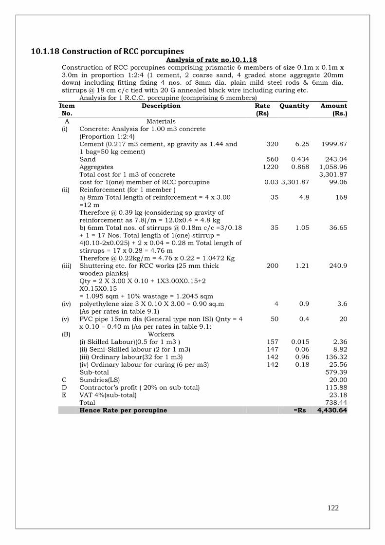
122
10.1.18 Construction of RCC porcupines
Analysis of rate no.10.1.18
Construction of RCC porcupines comprising prismatic 6 members of size 0.1m x 0.1m x
3.0m in proportion 1:2:4 (1 cement, 2 coarse sand, 4 graded stone aggregate 20mm down) including fitting fixing 4 nos. of 8mm dia. plain mild steel rods & 6mm dia.
stirrups @ 18 cm c/c tied with 20 G annealed black wire including curing etc.
Analysis for 1 R.C.C. porcupine (comprising 6 members)
Item
No.
Description Rate
(Rs)
Quantity Amount
(Rs.)
A Materials
(i) Concrete: Analysis for 1.00 m3 concrete
(Proportion 1:2:4)
Cement (0.217 m3 cement, sp gravity as 1.44 and
1 bag=50 kg cement)
320 6.25 1999.87
Sand 560 0.434 243.04 Aggregates 1220 0.868 1,058.96
Total cost for 1 m3 of concrete 3,301.87 cost for 1(one) member of RCC porcupine 0.03 3,301.87 99.06
(ii) Reinforcement (for 1 member )
a) 8mm Total length of reinforcement = 4 x 3.00
=12 m
Therefore @ 0.39 kg (considering sp gravity of
reinforcement as 7.8)/m = 12.0x0.4 = 4.8 kg
35 4.8 168
b) 6mm Total nos. of stirrups @ 0.18m c/c =3/0.18
+ 1 = 17 Nos. Total length of 1(one) stirrup =
4(0.10-2x0.025) + 2 x 0.04 = 0.28 m Total length of
stirrups = 17 x 0.28 = 4.76 m
Therefore @ 0.22kg/m = 4.76 x 0.22 = 1.0472 Kg
35 1.05 36.65
(iii) Shuttering etc. for RCC works (25 mm thick
wooden planks)
Qty = 2 X 3.00 X 0.10 + 1X3.00X0.15+2
X0.15X0.15
= 1.095 sqm + 10% wastage = 1.2045 sqm
200 1.21 240.9
(iv) polyethylene size 3 X 0.10 X 3.00 = 0.90 sq.m (As per rates in table 9.1)
4 0.9 3.6
(v) PVC pipe 15mm dia (General type non ISI) Qnty = 4
x 0.10 = 0.40 m (As per rates in table 9.1:
50 0.4 20
(B) Workers
(i) Skilled Labour)(0.5 for 1 m3 ) 157 0.015 2.36 (ii) Semi-Skilled labour (2 for 1 m3) 147 0.06 8.82
(iii) Ordinary labour(32 for 1 m3) 142 0.96 136.32
(iv) Ordinary labour for curing (6 per m3) 142 0.18 25.56
Sub-total 579.39
C Sundries(LS) 20.00
D Contractor‟s profit ( 20% on sub-total) 115.88 E VAT 4%(sub-total) 23.18
Total
738.44
Hence Rate per porcupine
=Rs 4,430.64

123
10.1.19 Transportation/carriage of RCC porcupines
Analysis of rate no.10.1.19
Local carriage of RCC porcupines (comprising 6 member of size 3.00 m x 0.10m x
0.10m) from more than 4 km including loading and unloading.
Total distance from cast-in-situ site to construction
site (considering distance of 25 km) in four trips
(2*25*4)
= 200 km
Nos of RCC members (150 member per trip by 10
ton capacity truck) carried in four trips/day= 4*150
= 600 Nos
Item
No.
Description Rate
(Rs)
Quantity Amount
(Rs.)
A Materials
(i) Hire charge of diesel truck including wages of
driver and handyman
1 1500 1500.00
(ii) Diesel required (Up & down) =200/3 42.35 66.67 2,823.33 (iii) Mobil 211 1 211.00
B Workers
(i) Ordinary labour for loading and unloading 142 6 852.00
Sub-total 5,386.33
C Sundries (LS) 20.00
D Contractor‟s profit ( 20% on sub-total) 1,077.27 E VAT 4% (on sub-total) 215.45
Total 6,699.05
Hence Rate per porcupine
=Rs 66.99

124
10.1.20 Laying of RCC porcupines without boats
Analysis of rate no.10.1.20
Assembling and placing of RCC porcupines in position at river bed, slope, dry river
bed, porcupines including carrying the RCC porcupine members by vehicle from the stack yard to the work site within 1 km including all leads and lifts, handling, local
carriage, loading, unloading etc.
Nos of RCC members assembled to make 6
member-RCC porcupine and placing of same at
bank
= 60 Nos
Item No.
Description Rate (Rs)
Quantity Amount (Rs.)
A Materials
(i) MS bolts of 12mm diameter 25cm long with 3mm
thick MS washer
60 nos. of bolt & nuts and 120 nos. of
washer/porcupine @ 0.25 Kg /bolt, nut & washer for fixing the piles(0.25*60=15 kg and rate of bolts,
nut and washer @ Rs 75/kg)
75 15 1,125
(ii) Jati Bamboo (including carrying charge to work
site) for making levers for placing in position
40 2 80
B Workers
(i) Ordinary labour for assembling of RCC Porcupine members with necessary nuts, bolts & washer,
carrying and placing porcupines in position in
shallow water
142 2 284
Sub-total 1489
C Sundries (LS) 20.00 D Contractor‟s profit ( 20% on sub-total) 297.80
E VAT 4% (on sub-total) 59.56
Total 1,866.36
Hence Rate per porcupine
=Rs 186.64
125
10.1.21 Laying of RCC porcupines with boats Analysis of rate no.10.1.21
Assembling on boat with engine RCC porcupines including launching the same from
twin board/flat barge on river bed along the alignment, including carrying the members from the stack-yard by vehicle to the worksite within 1 (one) Km, then carrying and
loading the same to the single engine board and transhipment to the Twin Engine Boat
(with Wooden Platform) / flat board barge including handling, local carriage, loading and
unloading etc. for all leads and lifts.
number of RCC porcupine members carried by a boat of 20 to 40 quintal capacity
= 60 No
number of trips by a boat of 20 to 40 quintal
capacity upto an average distance of 150 m in one
working day
= 10 Nos.
number of members carried by a boat of 20 to 40 quintal capacity considering 10 trips/day
= 600 Nos.
Item
No.
Description Rate
(Rs)
Quantity Amount
(Rs.)
A Materials
(i) Hire charge of single boat with boatman, fitted with
salwood platform and fitting devices for laying RCC porcupines in cage in the river bed at proper
position
1,200 1 1,200
(ii) MS bolts of 12mm diameter 25cm long with 3mm
thick MS washer 600 Nos. of bolt & nuts and 120
nos. of washer/porcupine @ 0.25 Kg /bolt, nut & washer for fixing the piles(0.25*600=150 kg and
rate of bolts, nut and washer @ Rs 75/kg)
75 150 11,250
(iii) Plastic empty container to be used as floats for
alignment (50 container @ Rs 10 each)
10 50 500
B Workers
(i) Semi-skilled labour for assembling of RCC Porcupine members with necessary nuts, bolts &
washer, carrying and placing porcupines in
position in shallow water
147 20 2,940
Sub-total 15,890
C Sundries (LS) 20.00 D Contractor‟s profit ( 20% on sub-total) 3,178
E VAT 4% (on sub-total) 635.60
Total 19,723.60
Hence rate per porcupine =Rs 197.24
10.2 References 1. Estimation and Costing in Civil Engineering” by B. N. Dutta.
2. Various detailed project report for flood management works
prepared by Government of Assam