Embed Size (px)
Citation preview
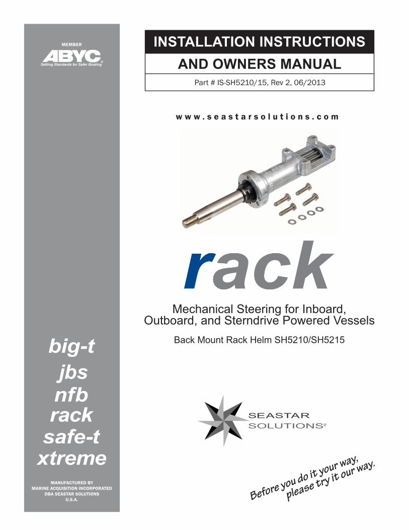
Mechanical Steering for Inboard, Outboard, and Sterndrive Powered Vessels
Back Mount Rack Helm SH5210/SH5215
w w w . s e a s t a r s o l u t i o n s . c o m
®
Before you do it your way,
please try it our way.
INSTALLATION INSTRUCTIONSAND OWNERS MANUAL
Part # IS-SH5210/15, Rev 2, 06/2013
nfb
MANUFACTURED BYMARINE ACQUISITION INCORPORATED
DBA SEASTAR SOLUTIONSU.S.A.
MEMBER
jbs
BACK MOUNT RACKHELM SH5210, SH5215Installer: these instructions contain important safety information and must be forwarded to the boat owner.
NOTICE
These instructions describe how to install helm assemblies for The Back Mount Rack steering system. Additional components required to complete the system are: •SSC134XXorSSC154XXCable(whereXXisthelengthinfeet)For
single cable system.•SSC135XXCable(whereXXisthelengthinfeet)Fordualcable
system.•SB39526BezelKit(Requiredtomounthelmtodash)•EngineConnectionKit(refertoSeaStarSolutionscatalog)•SteeringWheel(refertoSeaStarSolutionscatalog;Maximum wheeldiameter16")
Optional components are: •SB2744810°MountingKit•SB2744920°MountingKit•SA39531PFrictionDevice
Before starting installation read these instructions and engine makers instructions thoroughly. Failure to follow either of these instructions or incorrect assembly can result in loss of control and cause property damage, injury, or death.
DO NOT substitute parts from other manufacturers, they may cause a safety hazard for which SeaStar Solutions cannot accept responsibility. Use only SeaStar Solutions steering cables with this helm.
To avoid excessive steering loads, and to get the best steering performance, the outboard motor or outdrive trim tabs and tilt position must be adjusted as instructed in the motor manufacturers operation manual. Failure to do so can effect the performance of the boat and its safe operation which may cause property damage, injury, or death.
WARNING
WARNING
WARNING
DO NOT attach any electrical ground wires to the helm. This would result in an electrolytic reaction to the steering system that may result in system failure or greatly reduced service life.
WARNING
When replacing an existing steering system it is recommended that you stay with the style (rotary or rack) the boat manufacturer installed. Never change your steering from a dual cable to a single cable system, as this could cause an unsafe boating condition.
NOTICE
DISCLAIMER: This system is only recommended as replacement for the original system as installed by the boat manufacturer. SeaStar Solutions always recommends NFB™ helms for outboard applications. NFB helms lock out steering loads caused by propeller torque eliminating the driver fatigue normally experienced with a standard helm. Patented SeaStar Solutions steering helms are a drop in replacement for Back Mount Rack systems.
NOTICE
Page 2 of 8 SeaStar Solutions Installation Instructions and Owner’s Manual Telephone: 610-495-7011
Helms must not be disassembled for any reason. Failure to reassemble correctly may lead to total failure of the system, which could result in property damage, injury, or death.
WARNING
If possible the steering cable should be routed to the starboard side of the boat in order to balance engine torque.Whenroutingthecableselectapathwiththeminimumnumberofbends, making the bends as large as possible. DO NOT MAKE BENDS LESS THAN 8" RADIUS. Sharp or frequent bends will result in hard steeringandprematurecablewear.Whennecessarytopass through a bulkhead, a 1-1/2" diameter hole is required. The cable should be loosely clamped or tied for support at regular intervals.
Preparation for Installation
STEP 1. Locate the position for the Helm Assembly on the dashboard.
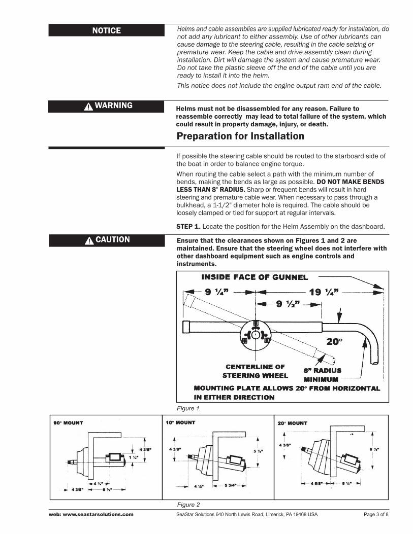
Figure 1.
Ensure that the clearances shown on Figures 1 and 2 are maintained. Ensure that the steering wheel does not interfere with other dashboard equipment such as engine controls and instruments.
CAUTION
Figure 2
Helms and cable assemblies are supplied lubricated ready for installation, do not add any lubricant to either assembly. Use of other lubricants can cause damage to the steering cable, resulting in the cable seizing or premature wear. Keep the cable and drive assembly clean during installation. Dirt will damage the system and cause premature wear. Do not take the plastic sleeve off the end of the cable until you are ready to install it into the helm. This notice does not include the engine output ram end of the cable.
NOTICE
web: www.seastarsolutions.com SeaStar Solutions 640 North Lewis Road, Limerick, PA 19468 USA Page 3 of 8

Figure 3.
Helm Assembly InstallationSTEP 1.Attachthehelmmountingplate(suppliedwiththeSB39526BezelKitalongwithmountinghardware)tothedashasdescribedinFigure3.
STEP 2.Positionthetemplate(Figure5)ontheconsoleordashboardatthelocationpreviouslymarked.Drillonehole21/4"diameterand3holes 5/16" diameter.
Template for 20° mount differs from template for 90° and 10° mounts. Ensure that the correct one is used.
NOTICE
Page 4 of 8 SeaStar Solutions Installation Instructions and Owner’s Manual Telephone: 610-495-7011
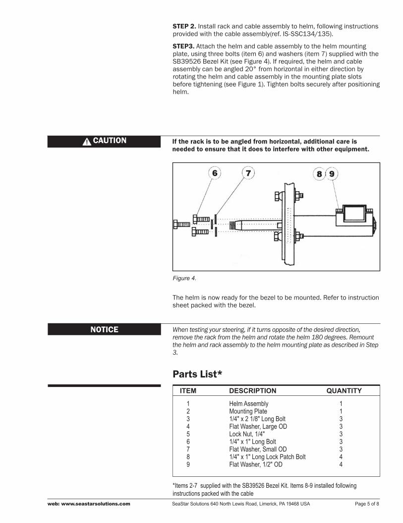
STEP 2. Install rack and cable assembly to helm, following instructions providedwiththecableassembly(ref.IS-SSC134/135).
STEP3. Attach the helm and cable assembly to the helm mounting plate,usingthreebolts(item6)andwashers(item7)suppliedwiththeSB39526BezelKit(seeFigure4).Ifrequired,thehelmandcableassemblycanbeangled20°fromhorizontalineitherdirectionbyrotating the helm and cable assembly in the mounting plate slots beforetightening(seeFigure1).Tightenboltssecurelyafterpositioninghelm.
If the rack is to be angled from horizontal, additional care is needed to ensure that it does to interfere with other equipment.
CAUTION
Figure 4.
Thehelmisnowreadyforthebezeltobemounted.Refertoinstructionsheetpackedwiththebezel.
Parts List*
*Items 2-7 supplied with the SB39526 Bezel Kit. Items 8-9 installed following instructions packed with the cable
123456789
113333344
Helm AssemblyMounting Plate1/4" x 2 1/8" Long BoltFlat Washer, Large ODLock Nut, 1/4"1/4" x 1" Long BoltFlat Washer, Small OD1/4" x 1" Long Lock Patch BoltFlat Washer, 1/2" OD
ITEM DESCRIPTION QUANTITY
When testing your steering, if it turns opposite of the desired direction, remove the rack from the helm and rotate the helm 180 degrees. Remount the helm and rack assembly to the helm mounting plate as described in Step 3.
NOTICE
web: www.seastarsolutions.com SeaStar Solutions 640 North Lewis Road, Limerick, PA 19468 USA Page 5 of 8
It is possible to over trim the engine and increase the steering torque to the point that the steering wheel cannot be turned, even though the torque is not felt at the wheel. This may give the impression that the steering is “locked”. This condition can occur more when jack plates are used to raise the engine on the transom, and can only be overcome by reducing the boat speed or engine trim out position. Until you are completely familiar with the boat and the effects of power trim, make all adjustments of trim with extreme caution.
Loosening or loss of one or more fasteners may cause failure of the steering system, resulting in loss of steering control and could cause property damage, injury, or death.
DO NOT cover cracks with tape or other sealants, this will create a hazard in which the cable can fail suddenly without warning, resulting in property damage, injury, or death.
DANGER
DANGER
1. After a few hours of operation and at frequent intervals thereafter, check all fasteners and the complete steering system for security and integrity.
2.Keepallmovingpartsfreefrombuild-upofsaltandotherforeignmaterial. This will affect their operation and create steering problems. Periodically remove the cable, clean support tube and telescopic end of cable thoroughly and lubricate with a waterproof marine grease.
3. Periodically inspect for corrosion. Any parts affected by corrosion mustbereplaced.Whenreplacinghardware,self-lockinghardwareasoriginally supplied must be used.
4. Periodically inspect steering cable for cracks or other damage. If any is found the cable must be replaced.
5. If cable is stiff in operation, it is unsafe to use and must be replaced immediately.
Boat builder and boat dealer, please supply these Installation Instructions and Owner’s Manual with the delivery of boat. Boat owner keep these instructions with your boat for future reference. Boat owner consult with your boat builder, boat dealer, or SeaStar Solutions if you have any questions regarding these instructions.
NOTICE
Operation & Maintenance Notes CAUTION
Page 6 of 8 SeaStar Solutions Installation Instructions and Owner’s Manual Telephone: 610-495-7011

✁
If you must photocopy this mounting template for use, check ALL measurements using a measuring device prior to using as a template.
NOTICE
Mou
ntin
g Te
mpl
ates
Figu
re 5
.
web: www.seastarsolutions.com SeaStar Solutions 640 North Lewis Road, Limerick, PA 19468 USA Page 7 of 8

©1998MARINEACQUISITION(US)INC.
PART #IS-SH5210/15,Rev2,07/2013
ISO 8848