Embed Size (px)
Citation preview
MEM Circuit Protection & Control The Guide to Circuit Protection & Control
Technical Support forElectrical Installations
2003 Issue
31258 MEM The Guide 1/7/03 16:02 Page 1
As a market-leading manufacturer of circuit protection and control equipment, Eaton
MEM’s world leading switch and fusegear, circuit breaker and wiring accessory products
are distributed across the globe.
Incorporating the latest technological advances, our products are the result of a
comprehensive ongoing development programme and comply with the industry’s most
rigorous quality standards. This all serves to make Eaton MEM an industry benchmark,
with unsurpassed quality and performance guaranteed.
This extensive product range, together with our lengthy experience and specialist
knowledge serves to make Eaton MEM the only source for your installation needs.
Eaton Corporation is a global $7.2 billion diversified industrial manufacturer that is
a leader in fluid power systems; electrical power quality, distribution and control;
automotive engine air management and fuel economy; and intelligent drivetrain
systems for fuel economy and safety in trucks. Eaton has 51,000 employees and sells
products in more than 50 countries. For more information, visit www.eaton.com.
www.memonline.com
T H E S O U R C E O F C I R C U I T P R O T E C T I O N S O L U T I O N S
31258 MEM The Guide 1/7/03 16:02 Page 2

CIRCUIT BREAKER PROTECTION 2MCB OPERATION 2PROTECTION OF CABLES 3DISCRIMINATION 6BACK-UP PROTECTION 10FUSE DATA FOR BACK-UP 11PROSPECTIVE FAULT CURRENT 12THERMAL DE-RATING 18PROTECTING LIGHTING CIRCUITS 20DC APPLICATIONS OF MEMSHIELD 2 MCBS 21MOTOR CIRCUIT PROTECTION 22TRANSFORMER PROTECTION 24
RCD’S & MODULAR CONTACTORS 26RCD SELECTION CRITERIA & OPERATING PRINCIPLES 26OPERATING CHARACTERISTICS 28SHOCK HAZARD CURVES 29RCD TROUBLE SHOOTING 30CAUSES OF SPASMODIC TRIPPING 31MODULAR CONTACTORS 32
CIRCUIT BREAKER DATA 36
HRC FUSELINK PROTECTION 48FEATURES 48CABLE PROTECTION 49PROTECTION AGAINST ELECTRIC SHOCK 50HIGH AMBIENT AIR TEMPERATURE 50TRANSFORMER, FLUORESCENT LIGHTING CIRCUITS 52CAPACITOR CIRCUITS 52DISCRIMINATION BETWEEN FUSELINKS 52BACK-UP PROTECTION 52MOTOR CIRCUIT PROTECTION 53CO-ORDINATION WITH SHORT CIRCUIT PROTECTIVE DEVICES 53TYPE 2 CO-ORDINATION 54TYPICAL TIME/CURRENT & CUT-OFF CURRENT CHARACTERISTICS 55
SELECTING THE CORRECT MOTOR STARTER 60SINGLE-PHASE OR THREE-PHASE? 60TYPE OF DUTY 62REDUCED VOLTAGE STARTING 63LOCAL OR AUTOMATIC CONTROL? 63ENVIRONMENTAL CONDITIONS 64FAULT FINDING 64SELECTION OF OVERLOAD RELAYS 65MOTOR FULL LOAD CURRENT TABLE 67SHORT CIRCUIT CO-ORDINATION 68IP RATING TABLES 69
C O N T E N T S
THE 16TH EDITION OF THE IEE WIRING REGULATIONS
(BS7671) DEFINES A FUSE AS:
“A device that by the fusing of one or more ofits specially designed and proportioned
components, opens the circuit in which it isinserted by breaking the current when thisexceeds a given value for a sufficient time.
The fuse comprises all the parts that form the complete device.”
A CIRCUIT BREAKER IS DEFINED AS:
“A device capable of making, carrying andbreaking normal load currents and also
making and automatically breaking underpredetermined conditions, abnormal currents
such as short-circuit currents. It is usuallyrequired to operate infrequently although some
types are suitable for frequent operation.”
EATON MEM IS UNIQUELY QUALIFIEDTO OFFER AUTHORITATIVE GUIDANCE.
Eaton MEM offers designers a wide spectrum
of protective devices available anywhere in the
world from a single source - from packaged
substations to final distribution; whether the
installation is based on fuses, circuit breakers
or a combination of both.
This guide is designed to provide essential
information on HRC fuses, circuit breakers
and motor control gear to designers, specifiers
and installers of electrical installations. The
characteristics, performance and benefits of
each device are described with the
requirements of the 16th Edition of the IEE
Wiring Regulations (BS7671) in mind.
To make full use of the latest generation of
Eaton MEM circuit protective devices the
installation designer should ensure the
suitability of the products for installation. To
this end it is a requirement for the installation
designer to determine the level of
discrimination that is required and to take
account of the need for back-up protection.
Using the information provided within this
document will assist in the design of a safe
and reliable system.
1
31258 MEM The Guide 1/7/03 16:02 Page 3
Miniature & Moulded Case C
THERMAL OPERATION
The long time protection (typically 1 second after energising) of the
MCB is defined as the thermal protection. The thermal component
of the MCBs protection is dealt with by a bi-metal blade (in the case
of Memshield 2 MCBs this is a multi-layer metallic blade which
provides a more linear and accurate movement than a conventional
bi-metallic blade).
When deflection of the bi-metal blade occurs, due to the heating
effect of the overload current, it moves a trip lever which trips the
latching mechanism and separates the main contacts under the
action of a spring. The movement of the bi-metal blade is calibrated
at manufacture to ensure correct performance in an ambient
temperature of 40ºC. Memshield 2 MCBs conform to the tripping
requirements of BSEN60898 as required by the wiring regulations
for overload protection of cables between ambients of 20ºC and
40ºC. This means that the Memshield 2 MCB is calibrated to meet
the higher ambient temperatures likely to be encountered when the
MCBs are grouped together.
Therefore, it is unlikely that any derating of the MCB is necessary in
normal use. 50ºC calibration is available.
Should further detailed information be required please contact our
Technical Services Department at Reddings Lane.
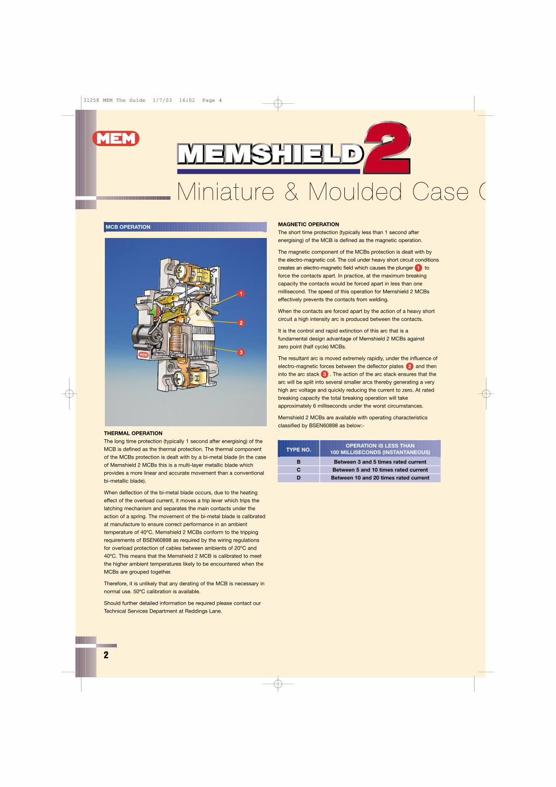
MAGNETIC OPERATION
The short time protection (typically less than 1 second after
energising) of the MCB is defined as the magnetic operation.
The magnetic component of the MCBs protection is dealt with by
the electro-magnetic coil. The coil under heavy short circuit conditions
creates an electro-magnetic field which causes the plunger (1) to
force the contacts apart. In practice, at the maximum breaking
capacity the contacts would be forced apart in less than one
millisecond. The speed of this operation for Memshield 2 MCBs
effectively prevents the contacts from welding.
When the contacts are forced apart by the action of a heavy short
circuit a high intensity arc is produced between the contacts.
It is the control and rapid extinction of this arc that is a
fundamental design advantage of Memshield 2 MCBs against
zero point (half cycle) MCBs.
The resultant arc is moved extremely rapidly, under the influence of
electro-magnetic forces between the deflector plates (2) and then
into the arc stack (3) . The action of the arc stack ensures that the
arc will be split into several smaller arcs thereby generating a very
high arc voltage and quickly reducing the current to zero. At rated
breaking capacity the total breaking operation will take
approximately 6 milliseconds under the worst circumstances.
Memshield 2 MCBs are available with operating characteristics
classified by BSEN60898 as below:-
OPERATION IS LESS THANTYPE NO. 100 MILLISECONDS (INSTANTANEOUS)
B Between 3 and 5 times rated current
C Between 5 and 10 times rated current
D Between 10 and 20 times rated current
3
1
2
1
2
3
MCB OPERATION
2
31258 MEM The Guide 1/7/03 16:02 Page 4
e Circuit Breaker Protection PROTECTION OF CABLES
PROTECTION OF CABLES IN ACCORDANCE WITH THE 16THEDITION OF THE IEE WIRING REGULATIONS (BS 7671)
PROTECTION AGAINST OVERCURRENT:
Overcurrent is defined in the 16th Edition of the IEE Wiring Regulationsas “a current exceeding the rated value. For conductors the rated valueis the current-carrying capacity.” Overcurrent can be divided into twoindividual levels of fault these being overload current and short circuitcurrent. These should be considered separately.
PROTECTION AGAINST OVERLOAD:
Overload is defined in the 16th Edition of the IEE Wiring Regulationsas “an over current occurring in a circuit which is electrically sound”.This may be the result of too many appliances drawing current froma system, a faulty appliance, or a motor subjected to mechanicaloverload. Regulation 433-01-01 of the 16th Edition of the IEE WiringRegulations defines the basic requirement for overload protection,“protective devices shall be provided to break an overload currentflowing in the circuit conductors before such a current could causea temperature rise detrimental to insulation, joints, terminations, orthe surroundings of the conductors. Circuits shall be so designedthat a small overload of long duration is unlikely to occur”.
CO-ORDINATION BETWEEN CONDUCTORS AND PROTECTIVE DEVICES:
It is apparent that Regulation 433-01-01 of the 16th Edition placesemphasis on the surroundings of the conductor as well as theconductor itself. Regulation 433-02-01 has laid down threeconditions to meet this requirement:a) lb ≤ lnb) ln ≤ lzc) l2 ≤ 1.45 lzWhere lb = design current of circuit
ln = nominal current of protective devicelz = current-carrying capacity of the cablel2 = minimum operating current of protective device
Miniature circuit breakers and moulded case circuit breakers normallyhave tripping factors of, or below this 1.45 figure so that if either ofthese devices is used in compliance with condition a) above willmean that condition b) is also met, thus providing overloadprotection to the conductors concerned.
PROTECTION AGAINST SHORT CIRCUIT:
Short circuit is defined in the 16th Edition of the IEE WiringRegulations as: “an overcurrent resulting from a fault of negligibleimpedance between live conductors having a difference in potentialunder normal operating conditions”. IEE Wiring Regulation 434-03-02 states that: “provided an overload protective devicecomplies with regulation 433 and also provides short circuitprotection the regulations are satisfied” without need for furtherproof. This is because if 433-03-02 is satisfied then the cable andthe overload rating of the device are compatible. However, wherethis condition is not met or in some doubt for example where aprotective device is provided for fault current protection only, as inan MCCB backing up a motor overload relay then IEE WiringRegulation 434-03-03 must be satisfied “where a protective deviceis provided for fault protection only, the clearance time of the device,under short circuit conditions, shall not result in the limitingtemperature of any conductors being exceeded.”
3
31258 MEM The Guide 1/7/03 16:02 Page 5
4
PROTECTION OF CABLES & CONDUCTORS AGAINSTSHORT CIRCUITS:
Regulation 434-03-03 of the IEE Wiring Regulations takes accountof the time by applying what is known as the adiabatic equation434-03-03 states:
“The time ‘t’ in which a given short circuit current will raise thetemperature of the conductors to the limiting temperature, can becalculated from the formula”:-
t = k2 s2
l2
Where t = duration in secss = cable cross section (mm2)l = effective short circuit current (Amps)k = a factor taking into account various criteria of
the conductor
e.g. for a p.v.c. insulated copper conductor k = 115 (see Table 1)for a few of the k values quoted in the 16th Edition of the IEE Wiring Regulations.
TABLE 1
Values of k for common materials, for calculation of the effects ofshort circuit current.
CONDUCTOR INSULATION MATERIAL
ASSUMED LIMITING
KMATERIAL
INITIAL FINAL
TEMPERATURE TEMPERATURE
ºC ºC
Copper pvc 70 160/140 115/10360ºC rubber 60 200 14185ºC rubber 85 220 13490ºC thermosetting 90 250 143Impregnated paper 80 160 108Mineral – exposed 70 160 115– not exposed 105 250 135
Aluminium pvc 70 160/140 76/6860ºC rubber 60 200 9385ºC rubber 85 220 8990ºC thermosetting 90 250 94Impregnated paper 80 160 71
NOTE: Where two values of limiting final temperature and of k are given the lower value relates to cables having conductors of greater than 300mm2 cross-sectional area.
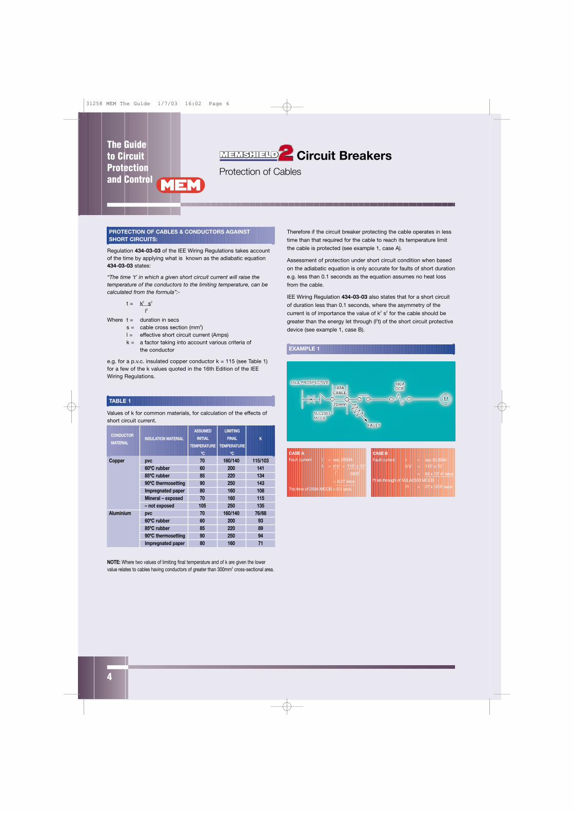
Therefore if the circuit breaker protecting the cable operates in less
time than that required for the cable to reach its temperature limit
the cable is protected (see example 1, case A).
Assessment of protection under short circuit condition when based
on the adiabatic equation is only accurate for faults of short duration
e.g. less than 0.1 seconds as the equation assumes no heat loss
from the cable.
IEE Wiring Regulation 434-03-03 also states that for a short circuit
of duration less than 0.1 seconds, where the asymmetry of the
current is of importance the value of k2 s2 for the cable should be
greater than the energy let through (l2t) of the short circuit protective
device (see example 1, case B).
EXAMPLE 1
CASE A
Fault current l = say 2800A
t = k2s2 = 1152 x 702
l2
28002
= 8.27 secs
Trip time of 250A MCCB = 0.3 secs.
CASE B
Fault current l = say 35,000A
k2s2 = 1152 x 702
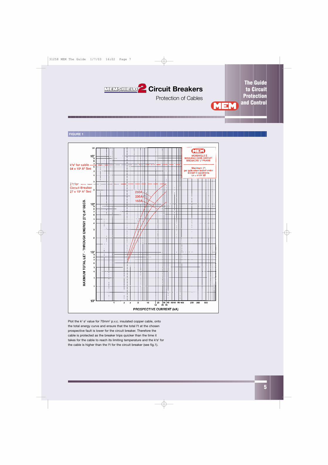
= 64 x 106 A2 secs
l2t let-through of MJLA2503 MCCB
l2t = 27 x 106A2 secs
Circuit Breakers Protection of Cables
The Guide to CircuitProtectionand Control
31258 MEM The Guide 1/7/03 16:02 Page 6
5
Plot the k2 s2 value for 70mm2 p.v.c. insulated copper cable, onto
the total energy curve and ensure that the total l2t at the chosen
prospective fault is lower for the circuit breaker. Therefore the
cable is protected as the breaker trips quicker than the time it
takes for the cable to reach its limiting temperature and the k2s2 for
the cable is higher than the l2t for the circuit breaker (see fig.1).
FIGURE 1
Circuit Breakers Protection of Cables
The Guide to Circuit
Protectionand Control
31258 MEM The Guide 1/7/03 16:02 Page 7
The Guide to CircuitProtectionand Control
6
DISCRIMINATION:
The 16th Edition of the IEE Wiring Regulations (BS7671) 533-01-06
requires that in an installation: “The characteristics and settings of
devices for overcurrent protection shall be such that any intended
discrimination in their operation is achieved”.
Whether fuses or circuit breakers are utilised in a distribution system
it is necessary to ensure that all the requirements of the 16th Edition
of the IEE Wiring Regulations are complied with.
Discrimination, also called selectivity, is considered to be achieved
when, under fault conditions the circuit breaker nearest the fault
operates rather than any of the circuit breakers or fuses upstream
of it (see example 2).
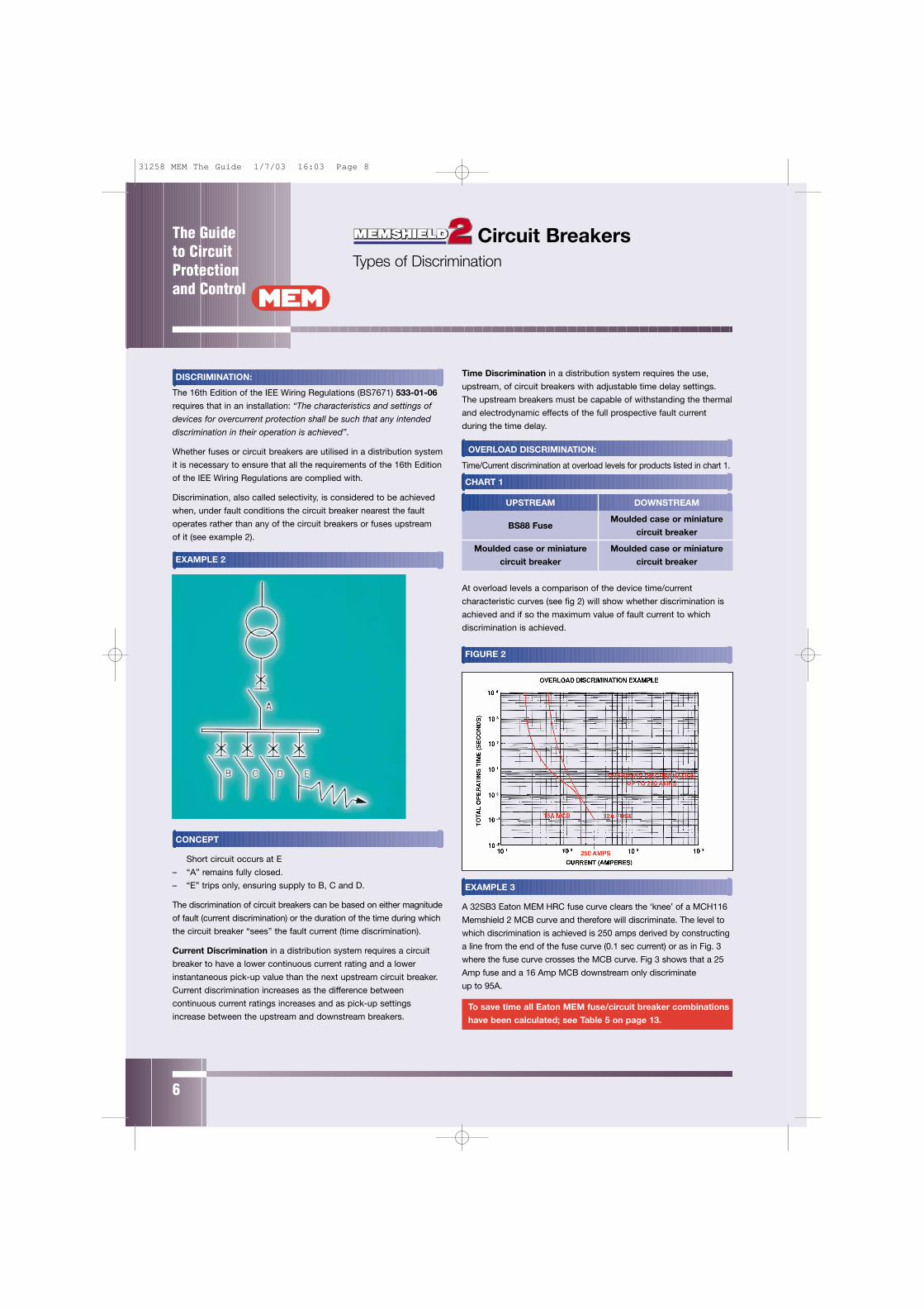
EXAMPLE 2
CONCEPT
Short circuit occurs at E
– “A” remains fully closed.
– “E” trips only, ensuring supply to B, C and D.
The discrimination of circuit breakers can be based on either magnitude
of fault (current discrimination) or the duration of the time during which
the circuit breaker “sees” the fault current (time discrimination).
Current Discrimination in a distribution system requires a circuit
breaker to have a lower continuous current rating and a lower
instantaneous pick-up value than the next upstream circuit breaker.
Current discrimination increases as the difference between
continuous current ratings increases and as pick-up settings
increase between the upstream and downstream breakers.
Time Discrimination in a distribution system requires the use,
upstream, of circuit breakers with adjustable time delay settings.
The upstream breakers must be capable of withstanding the thermal
and electrodynamic effects of the full prospective fault current
during the time delay.
OVERLOAD DISCRIMINATION:
Time/Current discrimination at overload levels for products listed in chart 1.
CHART 1
UPSTREAM DOWNSTREAM
BS88 FuseMoulded case or miniature
circuit breaker
Moulded case or miniature Moulded case or miniature
circuit breaker circuit breaker
At overload levels a comparison of the device time/current
characteristic curves (see fig 2) will show whether discrimination is
achieved and if so the maximum value of fault current to which
discrimination is achieved.
FIGURE 2
EXAMPLE 3
A 32SB3 Eaton MEM HRC fuse curve clears the ‘knee’ of a MCH116
Memshield 2 MCB curve and therefore will discriminate. The level to
which discrimination is achieved is 250 amps derived by constructing
a line from the end of the fuse curve (0.1 sec current) or as in Fig. 3
where the fuse curve crosses the MCB curve. Fig 3 shows that a 25
Amp fuse and a 16 Amp MCB downstream only discriminate
up to 95A.
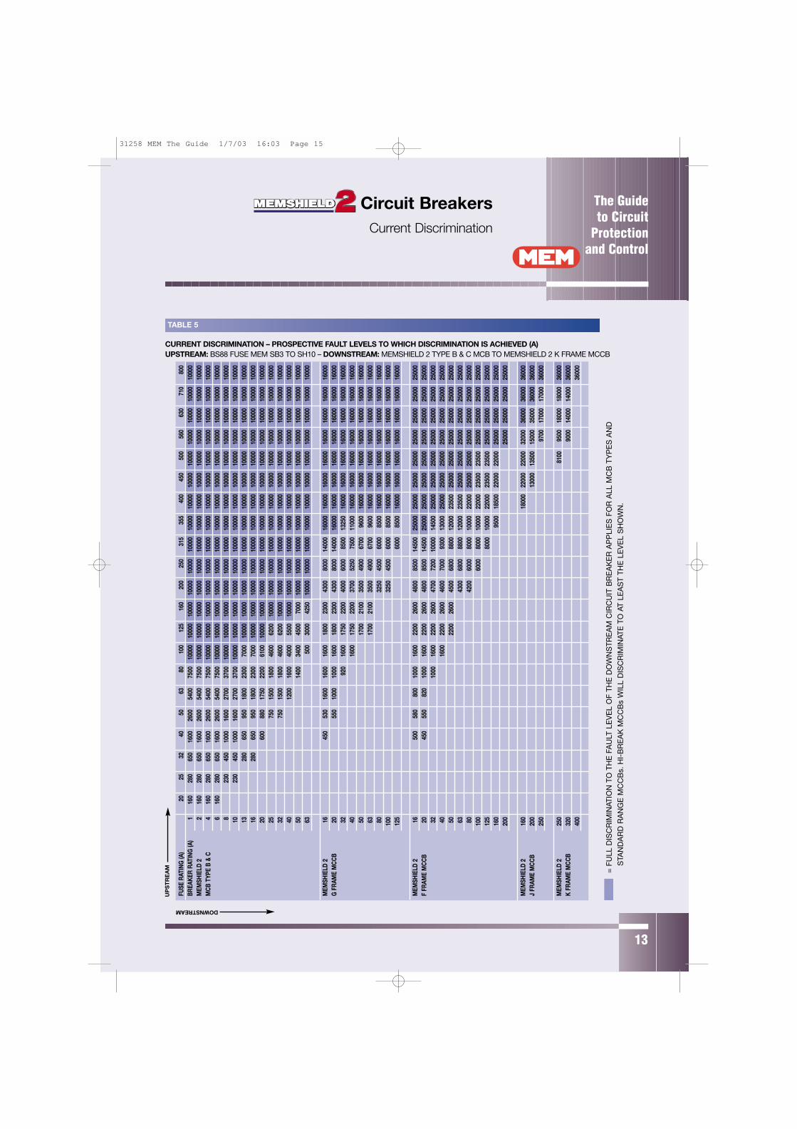
To save time all Eaton MEM fuse/circuit breaker combinations
have been calculated; see Table 5 on page 13.
Circuit Breakers Types of Discrimination
31258 MEM The Guide 1/7/03 16:03 Page 8

The Guide to Circuit
Protectionand Control
7
FIGURE 3 Short Circuit Discrimination: Current discrimination at short circuit
levels for products in chart 2.
CHART 2
UPSTREAM DOWNSTREAM
BS88 FuseMoulded case or miniature
circuit breaker
Where high prospective fault levels exist at the circuit breaker
distribution point then discrimination at short circuit levels
should be considered. This requires comparison of the
devices total let through energy and pre-arcing energy for
the prospective fault level concerned.
Discrimination will be obtained at all fault levels for the circuit
breaker when its total let through energy (l2t) is less than the
pre-arcing energy (l2t) of the fuse nearer the supply.
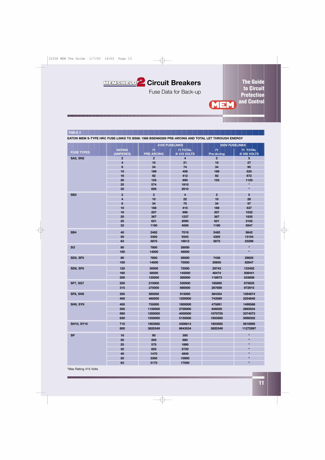
The information for Eaton MEMs BS88 HRC fuse range can be
extracted from curves and is presented in tabular form
(see table 2 on page 11). This can be compared with
Memshield 2 miniature circuit breaker and moulded case
circuit breaker total let through energy curves an example
being Figure 4.
EXAMPLE 4
The total let through energy of a 32A Memshield 2 miniature circuit
breaker experiencing a fault of 5kA will be 22000 A2s (See Figure 4).
Relating this value to the pre-arcing value of the upstream fuse
(see table 2) it can be seen that the lowest rated fuse providing
discrimination is the 125SF6, as its pre-arcing energy is greater
than the total let through energy of a 32A Memshield 2
MCB at 5kA ie.
Fuse pre-arcing MCB Total let through
Upstream Downstream
29743A2s > 22000A
2s
Fuse Circuit Breaker
Full discrimination is achieved at 5kA.
This has been calculated for every combination of Memshield 2
circuit breakers and Eaton MEM BS88 fuselinks – see Table 5 on
page 13.
FIGURE 4
Circuit Breakers Types of Discrimination
31258 MEM The Guide 1/7/03 16:03 Page 9
The Guide to CircuitProtectionand Control
8
SHORT CIRCUIT DISCRIMINATION:
Current discrimination at short circuit levels for products listed in
chart 3.
CHART 3
UPSTREAM DOWNSTREAM
Category A MCCB Category A MCCB
Category A MCCB MCB
Category A moulded case circuit breakers are defined in
BSEN60947-2 (IEC 60947-2), summarised as follows:-
– Category “A” applies to circuit breakers not specifically intended
for selectivity (discrimination) under short circuit conditions.
Discrimination is possible but not on a time basis. These are
current limiting type moulded case circuit breakers and as such it
is not possible to assess short circuit discrimination by overlapping
time current curves. Discrimination in the overload portion of the
time/current characteristic can be shown by overlapping the time
current curves but to determine short circuit discrimination a
different technique must be applied.
Discrimination between two circuit breakers both of category A
current limiting type cannot be determined by comparing the
individual l2t figures of the circuit breakers. This is not possible
because unlike fuses, circuit breakers have no “fixed” pre-arcing
energy. The nearest equivalent is the delatching energy; the point
at which the tripping mechanism starts to open and is past its
“point of no return”.
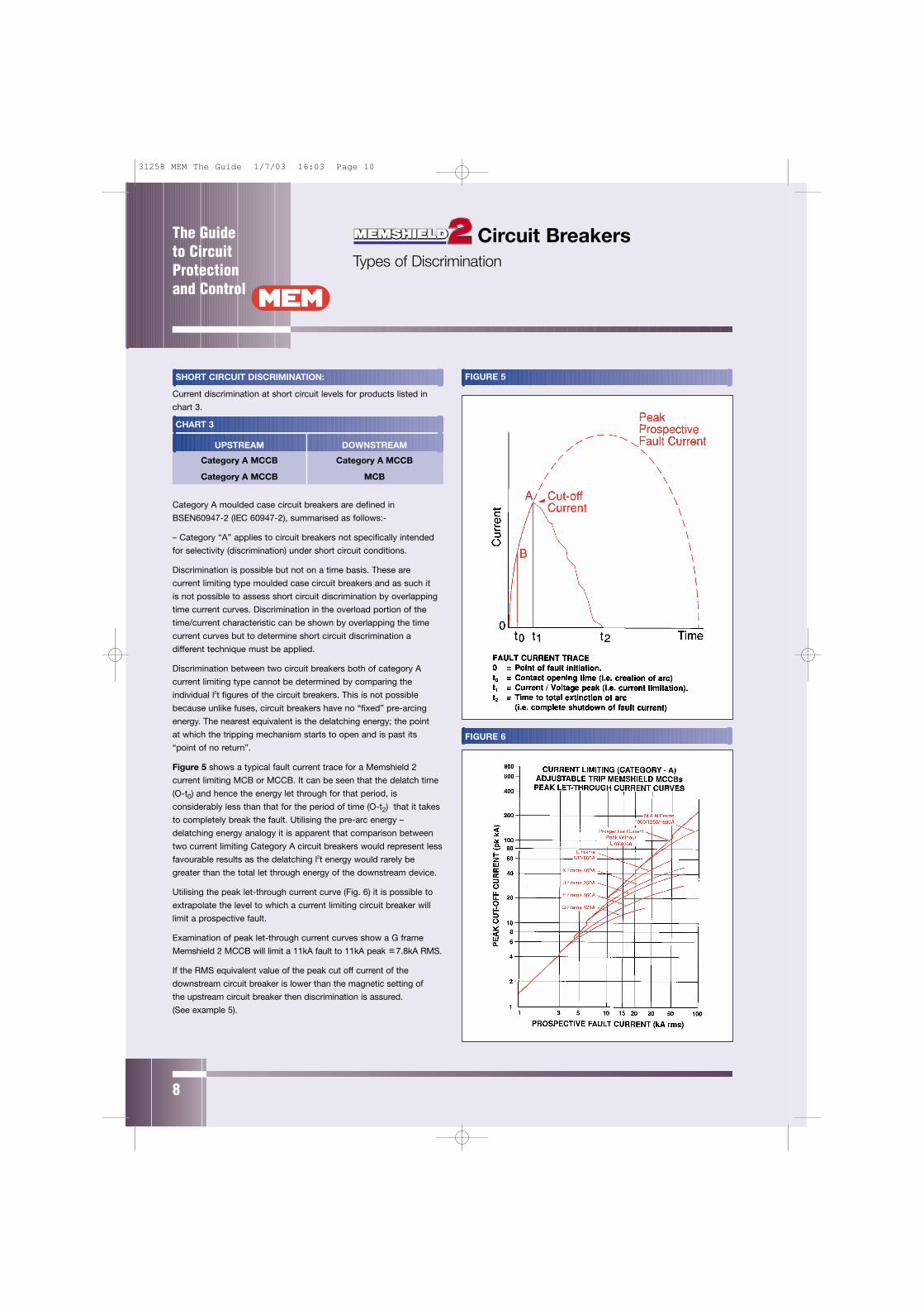
Figure 5 shows a typical fault current trace for a Memshield 2
current limiting MCB or MCCB. It can be seen that the delatch time
(O-t0) and hence the energy let through for that period, is
considerably less than that for the period of time (O-t2) that it takes
to completely break the fault. Utilising the pre-arc energy –
delatching energy analogy it is apparent that comparison between
two current limiting Category A circuit breakers would represent less
favourable results as the delatching l2t energy would rarely be
greater than the total let through energy of the downstream device.
Utilising the peak let-through current curve (Fig. 6) it is possible to
extrapolate the level to which a current limiting circuit breaker will
limit a prospective fault.
Examination of peak let-through current curves show a G frame
Memshield 2 MCCB will limit a 11kA fault to 11kA peak 7.8kA RMS.
If the RMS equivalent value of the peak cut off current of the
downstream circuit breaker is lower than the magnetic setting of
the upstream circuit breaker then discrimination is assured.
(See example 5).
FIGURE 5
Circuit Breakers Types of Discrimination
FIGURE 6
31258 MEM The Guide 1/7/03 16:03 Page 10
The Guide to Circuit
Protectionand Control
9
Category B moulded case circuit breakers are defined in
BSEN60947-2 (IEC 60947-2), summarised as follows:-
– Category “B” applies to circuit breakers specifically intended
for selectivity under short circuit conditions with respect to other
short-circuit protective devices in series on the load side.
These circuit breakers are equipped with an intentional short time
delay. This ensures that the upstream circuit breaker remains
closed long enough under short circuit conditions to allow the
downstream circuit protective device to clear the fault (see Fig 7).
In contrast with the current limiting category A type circuit breakers
this type of circuit breaker is designed to withstand the rated short
time withstand current (lcw) for the time duration dependent on
the maximum time delay setting made on the circuit breaker.
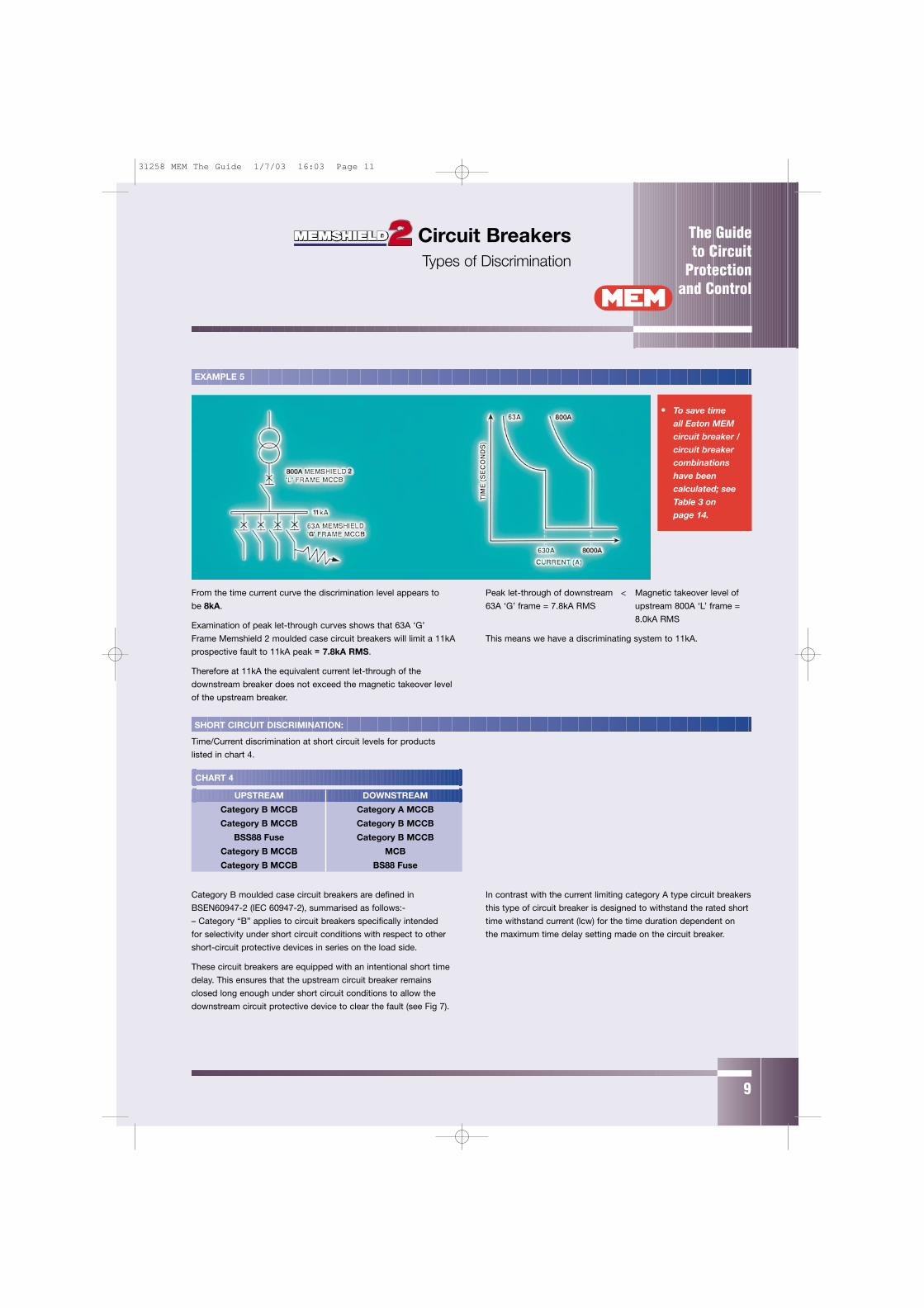
From the time current curve the discrimination level appears to
be 8kA.
Examination of peak let-through curves shows that 63A ‘G’
Frame Memshield 2 moulded case circuit breakers will limit a 11kA
prospective fault to 11kA peak 7.8kA RMS.
Therefore at 11kA the equivalent current let-through of the
downstream breaker does not exceed the magnetic takeover level
of the upstream breaker.
Peak let-through of downstream < Magnetic takeover level of
63A ‘G’ frame = 7.8kA RMS upstream 800A ‘L’ frame =
8.0kA RMS
This means we have a discriminating system to 11kA.
CHART 4
UPSTREAM DOWNSTREAM
Category B MCCB Category A MCCB
Category B MCCB Category B MCCB
BSS88 Fuse Category B MCCB
Category B MCCB MCB
Category B MCCB BS88 Fuse
EXAMPLE 5
• To save time all Eaton MEMcircuit breaker /circuit breakercombinationshave beencalculated; seeTable 3 on page 14.
SHORT CIRCUIT DISCRIMINATION:
Time/Current discrimination at short circuit levels for products
listed in chart 4.
Circuit Breakers Types of Discrimination
31258 MEM The Guide 1/7/03 16:03 Page 11
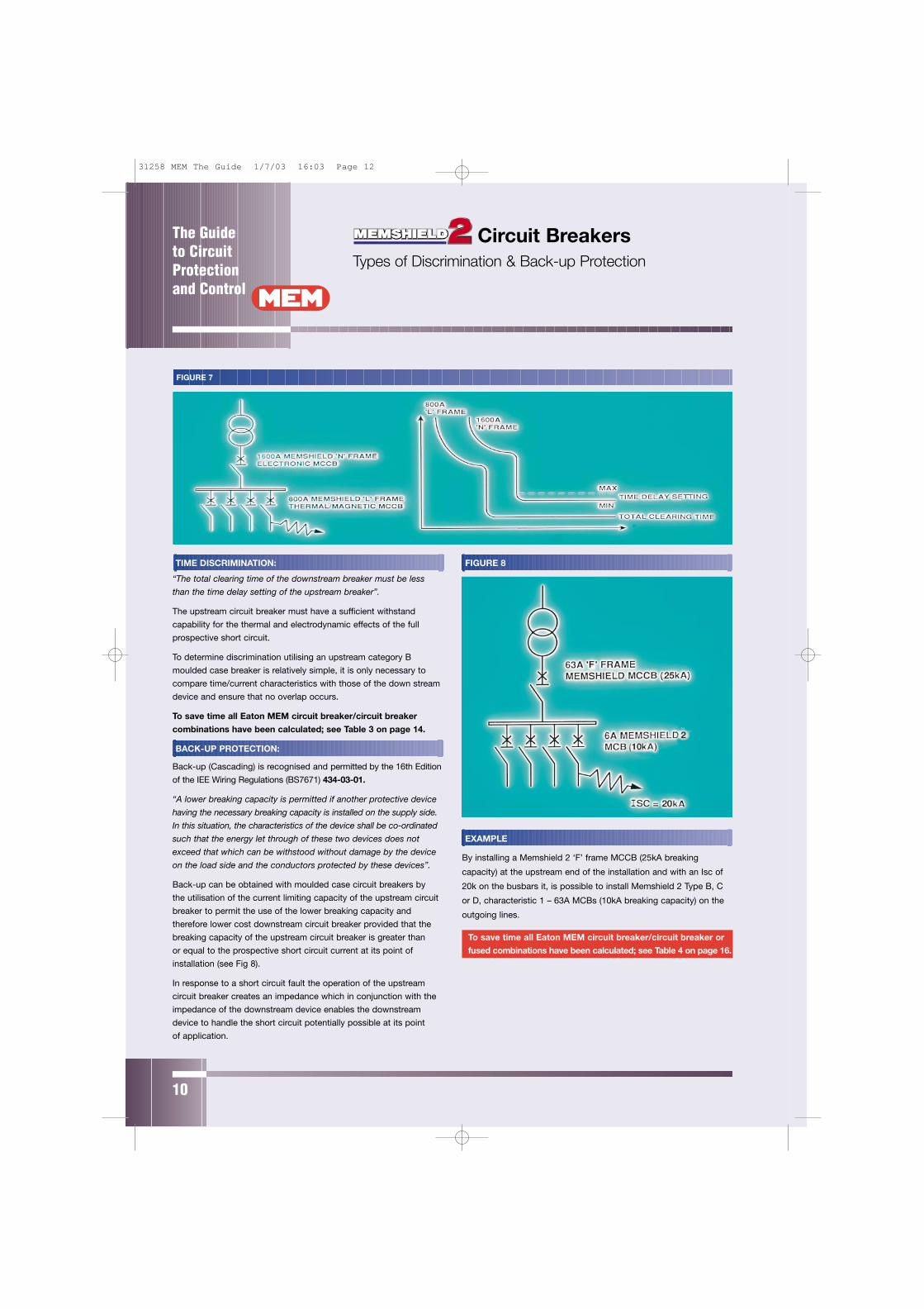
FIGURE 8
EXAMPLE
By installing a Memshield 2 ‘F’ frame MCCB (25kA breaking
capacity) at the upstream end of the installation and with an Isc of
20k on the busbars it, is possible to install Memshield 2 Type B, C
or D, characteristic 1 – 63A MCBs (10kA breaking capacity) on the
outgoing lines.
To save time all Eaton MEM circuit breaker/circuit breaker or
fused combinations have been calculated; see Table 4 on page 16.
The Guide to CircuitProtectionand Control
10
TIME DISCRIMINATION:
“The total clearing time of the downstream breaker must be less
than the time delay setting of the upstream breaker”.
The upstream circuit breaker must have a sufficient withstand
capability for the thermal and electrodynamic effects of the full
prospective short circuit.
To determine discrimination utilising an upstream category B
moulded case breaker is relatively simple, it is only necessary to
compare time/current characteristics with those of the down stream
device and ensure that no overlap occurs.
To save time all Eaton MEM circuit breaker/circuit breaker
combinations have been calculated; see Table 3 on page 14.
BACK-UP PROTECTION:
Back-up (Cascading) is recognised and permitted by the 16th Edition
of the IEE Wiring Regulations (BS7671) 434-03-01.
“A lower breaking capacity is permitted if another protective device
having the necessary breaking capacity is installed on the supply side.
In this situation, the characteristics of the device shall be co-ordinated
such that the energy let through of these two devices does not
exceed that which can be withstood without damage by the device
on the load side and the conductors protected by these devices”.
Back-up can be obtained with moulded case circuit breakers by
the utilisation of the current limiting capacity of the upstream circuit
breaker to permit the use of the lower breaking capacity and
therefore lower cost downstream circuit breaker provided that the
breaking capacity of the upstream circuit breaker is greater than
or equal to the prospective short circuit current at its point of
installation (see Fig 8).
In response to a short circuit fault the operation of the upstream
circuit breaker creates an impedance which in conjunction with the
impedance of the downstream device enables the downstream
device to handle the short circuit potentially possible at its point
of application.
FIGURE 7
Circuit Breakers Types of Discrimination & Back-up Protection
31258 MEM The Guide 1/7/03 16:03 Page 12
The Guide to Circuit
Protectionand Control
11
SO 80 7800 26000 *100 14000 46000 *
SD6, SF6 125 30000 75500 29743 133402160 58500 145000 46474 208441200 120000 300000 118973 533608
SH10, SY10 710 1903565 4306813 1903565 5616995800 3820349 8643534 3820349 11272997
SP 16 90 300 *20 205 680 *25 575 1890 *32 825 2720 *40 1470 4840 *50 3300 10900 *63 5170 17000 *
*Max Rating 415 Volts
SH9, SY9 450 755000 1900000 475891 1499588500 1100000 2700000 846029 2665934560 1200000 4000000 1070755 3374073630 1550000 5150000 1903565 5998352
SF8, SH8 355 365000 915000 364354 1594874400 480000 1200000 743580 3254846
SF7, SG7 250 210000 530000 185895 675635315 270000 680000 267689 972915
SD5, SF5 80 7800 26000 7436 29825100 14000 75500 20655 82847
SB4 40 2482 7019 2482 984250 3305 9345 3305 1310463 5875 16612 5875 23296
SB3 2 2 4 2 54 10 22 10 286 34 75 34 9710 188 415 188 53716 207 696 207 103220 367 1237 367 183525 621 2090 621 310232 1190 4006 1190 5947
TABLE 2
EATON MEM S-TYPE HRC FUSE-LINKS TO BS88: 1988 BSEN60269 PRE-ARCING AND TOTAL LET THROUGH ENERGY
FUSE TYPESRATING l2t l2t TOTAL l2t l2t TOTAL
(AMPERES) PRE-ARCING @ 415 VOLTS Pre-Arcing @ 550 VOLTSSA2, SN2 2 2 4 2 5
4 10 21 10 276 34 74 34 9510 188 408 188 52516 92 412 92 67220 155 690 155 112025 574 1810 *32 826 2610 *
550V FUSELINKS415V FUSELINKS
Circuit Breakers Fuse Data for Back-up
31258 MEM The Guide 1/7/03 16:03 Page 13
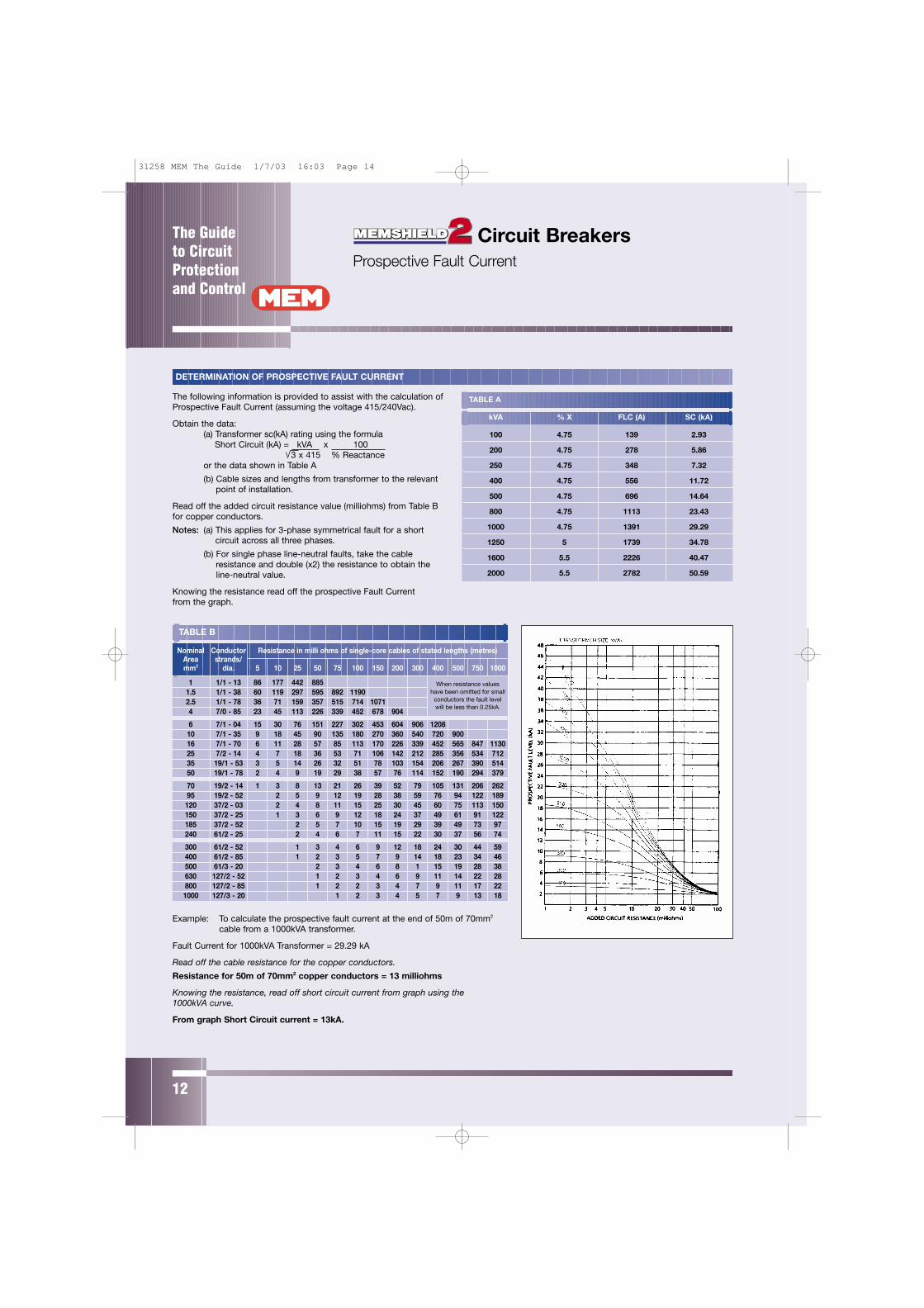
DETERMINATION OF PROSPECTIVE FAULT CURRENT
The following information is provided to assist with the calculation ofProspective Fault Current (assuming the voltage 415/240Vac).
Obtain the data:(a) Transformer sc(kA) rating using the formula
Short Circuit (kA) = kVA x 100 3 x 415 % Reactance
or the data shown in Table A
(b) Cable sizes and lengths from transformer to the relevant point of installation.
Read off the added circuit resistance value (milliohms) from Table Bfor copper conductors.
Notes: (a) This applies for 3-phase symmetrical fault for a short circuit across all three phases.
(b) For single phase line-neutral faults, take the cable resistance and double (x2) the resistance to obtain the line-neutral value.
Knowing the resistance read off the prospective Fault Current from the graph.
Example: To calculate the prospective fault current at the end of 50m of 70mm2
cable from a 1000kVA transformer.
Fault Current for 1000kVA Transformer = 29.29 kA
Read off the cable resistance for the copper conductors.
Resistance for 50m of 70mm2 copper conductors = 13 milliohms
Knowing the resistance, read off short circuit current from graph using the 1000kVA curve.
From graph Short Circuit current = 13kA.
The Guide to CircuitProtectionand Control
12
Circuit Breakers Prospective Fault Current
TABLE A
kVA % X FLC (A) SC (kA)
100 4.75 139 2.93
200 4.75 278 5.86
250 4.75 348 7.32
400 4.75 556 11.72
500 4.75 696 14.64
800 4.75 1113 23.43
1000 4.75 1391 29.29
1250 5 1739 34.78
1600 5.5 2226 40.47
2000 5.5 2782 50.59
Nominal ConductorArea strands/mm2 dia. 5 10 25 50 75 100 150 200 300 400 500 750 1000
1 1/1 - 13 86 177 442 8851.5 1/1 - 38 60 119 297 595 892 11902.5 1/1 - 78 36 71 159 357 515 714 10714 7/0 - 85 23 45 113 226 339 452 678 904
6 7/1 - 04 15 30 76 151 227 302 453 604 906 120810 7/1 - 35 9 18 45 90 135 180 270 360 540 720 90016 7/1 - 70 6 11 28 57 85 113 170 226 339 452 565 847 113025 7/2 - 14 4 7 18 36 53 71 106 142 212 285 356 534 71235 19/1 - 53 3 5 14 26 32 51 78 103 154 206 267 390 51450 19/1 - 78 2 4 9 19 29 38 57 76 114 152 190 294 379
70 19/2 - 14 1 3 8 13 21 26 39 52 79 105 131 206 26295 19/2 - 52 2 5 9 12 19 28 38 59 76 94 122 189120 37/2 - 03 2 4 8 11 15 25 30 45 60 75 113 150150 37/2 - 25 1 3 6 9 12 18 24 37 49 61 91 122185 37/2 - 52 2 5 7 10 15 19 29 39 49 73 97240 61/2 - 25 2 4 6 7 11 15 22 30 37 56 74
300 61/2 - 52 1 3 4 6 9 12 18 24 30 44 59400 61/2 - 85 1 2 3 5 7 9 14 18 23 34 46500 61/3 - 20 2 3 4 6 8 1 15 19 28 38630 127/2 - 52 1 2 3 4 6 9 11 14 22 28800 127/2 - 85 1 2 2 3 4 7 9 11 17 22
1000 127/3 - 20 1 2 3 4 5 7 9 13 18
Resistance in milli ohms of single-core cables of stated lengths (metres)
TABLE B
When resistance values have been omitted for small
conductors the fault level will be less than 0.25kA.
31258 MEM The Guide 1/7/03 16:03 Page 14
The Guide to Circuit
Protectionand Control
13
315
355
400
450
500
560
630
710
800
1000
010
000
1000
010
000
1000
010
000
1000
010
000
1000
010
000
1000
010
000
1000
010
000
1000
010
000
1000
010
000
1000
010
000
1000
010
000
1000
010
000
1000
010
000
1000
010
000
1000
010
000
1000
010
000
1000
010
000
1000
010
000
1000
010
000
1000
010
000
1000
010
000
1000
010
000
1000
010
000
1000
010
000
1000
010
000
1000
010
000
1000
010
000
1000
010
000
1000
010
000
1000
010
000
1000
010
000
1000
010
000
1000
010
000
1000
010
000
1000
010
000
1000
010
000
1000
010
000
1000
010
000
1000
010
000
1000
010
000
1000
010
000
1000
010
000
1000
010
000
1000
010
000
1000
010
000
1000
010
000
1000
010
000
1000
010
000
1000
010
000
1000
010
000
1000
010
000
1000
010
000
1000
010
000
1000
010
000
1000
010
000
1000
010
000
1000
010
000
1000
010
000
1000
010
000
1000
010
000
1000
010
000
1000
010
000
1000
010
000
1400
016
000
1600
016
000
1600
016
000
1600
016
000
1600
014
000
1600
016
000
1600
016
000
1600
016
000
1600
016
000
8500
1325
016
000
1600
016
000
1600
016
000
1600
016
000
7500
1100
016
000
1600
016
000
1600
016
000
1600
016
000
6700
9600
1600
016
000
1600
016
000
1600
016
000
1600
067
0096
0016
000
1600
016
000
1600
016
000
1600
016
000
6000
8500
1600
016
000
1600
016
000
1600
016
000
1600
060
0085
0016
000
1600
016
000
1600
016
000
1600
016
000
6000
8500
1600
016
000
1600
016
000
1600
016
000
1600
0
1450
025
000
2500
025
000
2500
025
000
2500
025
000
2500
014
500
2500
025
000
2500
025
000
2500
025
000
2500
025
000
1000
014
500
2500
025
000
2500
025
000
2500
025
000
2500
093
0013
000
2500
025
000
2500
025
000
2500
025
000
2500
088
0012
000
2350
025
000
2500
025
000
2500
025
000
2500
088
0012
000
2350
025
000
2500
025
000
2500
025
000
2500
080
0010
000
2200
025
000
2500
025
000
2500
025
000
2500
080
0010
000
2200
023
500
2350
025
000
2500
025
000
2500
080
0010
000
2200
023
500
2350
025
000
2500
025
000
2500
095
0018
500
2200
022
000
2500
025
000
2500
025
000
2500
025
000
2500
025
000
1800
022
000
2200
032
000
3600
036
000
3600
013
000
1350
015
000
3500
036
000
3600
097
0017
000
1700
036
000
8100
9500
1800
018
000
3600
090
0014
000
1400
036
000
3600
0
FUSE
RAT
ING
(A)
2025
3240
5063
8010
012
516
020
025
0BR
EAKE
R RA
TING
(A)
116
028
065
016
0026
0054
0075
0010
000
1000
010
000
1000
010
000
MEM
SHIE
LD 2
216
028
065
016
0026
0054
0075
0010
000
1000
010
000
1000
010
000
MCB
TYP
E B
& C
416
028
065
016
0026
0054
0075
0010
000
1000
010
000
1000
010
000
616
028
065
016
0026
0054
0075
0010
000
1000
010
000
1000
010
000
823
045
010
0016
0027
0037
0010
000
1000
010
000
1000
010
000
1023
045
010
0016
0027
0037
0010
000
1000
010
000
1000
010
000
1328
065
095
018
0023
0070
0010
000
1000
010
000
1000
016
280
650
950
1800
2300
7000
1000
010
000
1000
010
000
2060
088
017
5022
0061
0010
000
1000
010
000
1000
025
750
1500
1800
4600
6200
1000
010
000
1000
032
750
1500
1800
4600
6200
1000
010
000
1000
040
1200
1600
4000
5500
1000
010
000
1000
050
1400
3400
4500
7000
1000
010
000
6350
030
0042
5010
000
1000
0
MEM
SHIE
LD 2
1645
053
016
0016
0016
0018
0023
0043
0080
00G
FRA
ME
MCC
B20
550
1000
1000
1600
1800
2300
4300
8000
3292
016
0017
5022
0040
0060
0040
1600
1750
2200
3700
5250
5017
0021
0035
0049
0063
1700
2100
3500
4900
8032
5045
0010
032
5045
0012
5
MEM
SHIE
LD 2
1650
058
080
010
0016
0022
0026
0048
0085
00F
FRAM
E M
CCB
2045
055
082
010
0016
0022
0026
0048
0085
0032
1000
1600
2200
2600
4700
7200
4016
0022
0026
0046
0070
0050
2200
2600
4500
6800
6343
0068
0080
4200
6000
100
6000
125
160
200
MEM
SHIE
LD 2
160
J FR
AME
MCC
B20
025
0
MEM
SHIE
LD 2
250
K FR
AME
MCC
B32
040
0
CURRENT DISCRIMINATION – PROSPECTIVE FAULT LEVELS TO WHICH DISCRIMINATION IS ACHIEVED (A)UPSTREAM: BS88 FUSE MEM SB3 TO SH10 – DOWNSTREAM: MEMSHIELD 2 TYPE B & C MCB TO MEMSHIELD 2 K FRAME MCCB
= F
ULL
DIS
CR
IMIN
ATIO
N T
O T
HE
FA
ULT
LE
VE
L O
F TH
E D
OW
NS
TRE
AM
CIR
CU
IT B
RE
AK
ER
AP
PLI
ES
FO
R A
LL M
CB
TY
PE
S A
ND
STA
ND
AR
D R
AN
GE
MC
CB
s. H
I-B
RE
AK
MC
CB
s W
ILL
DIS
CR
IMIN
ATE
TO
AT
LEA
ST
THE
LE
VE
L S
HO
WN
.
DOWNSTREAM
UP
ST
RE
AM
TABLE 5
Circuit Breakers Current Discrimination
31258 MEM The Guide 1/7/03 16:03 Page 15
14
The Guide to CircuitProtectionand Control
DO
WN
ST
RE
AM
UPSTREAM
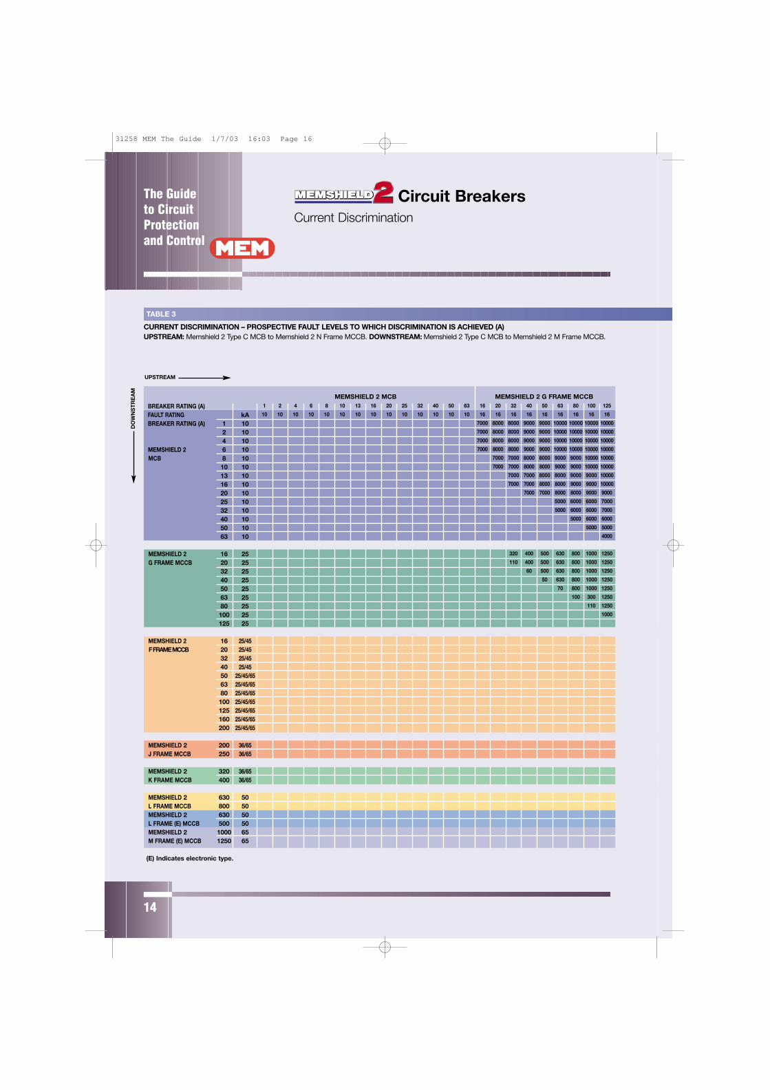
TABLE 3
CURRENT DISCRIMINATION – PROSPECTIVE FAULT LEVELS TO WHICH DISCRIMINATION IS ACHIEVED (A)UPSTREAM: Memshield 2 Type C MCB to Memshield 2 N Frame MCCB. DOWNSTREAM: Memshield 2 Type C MCB to Memshield 2 M Frame MCCB.
MEMSHIELD 2 MCB1 2 4 6 8 10 13 16 20 25 32 40 50 63
10 10 10 10 10 10 10 10 10 10 10 10 10 10BREAKER RATING (A)FAULT RATING kABREAKER RATING (A) 1 10
2 104 10
MEMSHIELD 2 6 10MCB 8 10
10 1013 1016 1020 1025 1032 1040 1050 1063 10
MEMSHIELD 2 16 25G FRAME MCCB 20 25
32 2540 2550 2563 2580 25100 25125 25
MEMSHIELD 2 16 25/45F FRAME MCCB 20 25/45
32 25/4540 25/4550 25/45/6563 25/45/6580 25/45/65100 25/45/65125 25/45/65160 25/45/65200 25/45/65
MEMSHIELD 2 200 36/65J FRAME MCCB 250 36/65
MEMSHIELD 2 320 36/65K FRAME MCCB 400 36/65
MEMSHIELD 2 630 50L FRAME MCCB 800 50MEMSHIELD 2 630 50L FRAME (E) MCCB 500 50MEMSHIELD 2 1000 65M FRAME (E) MCCB 1250 65
(E) Indicates electronic type.
Circuit Breakers Current Discrimination
MEMSHIELD 2 G FRAME MCCB16 20 32 40 50 63 80 100 125
16 16 16 16 16 16 16 16 16
7000 8000 8000 9000 9000 10000 10000 10000 10000
7000 8000 8000 9000 9000 10000 10000 10000 10000
7000 8000 8000 9000 9000 10000 10000 10000 10000
7000 8000 8000 9000 9000 10000 10000 10000 10000
7000 7000 8000 8000 9000 9000 10000 10000
7000 7000 8000 8000 9000 9000 10000 10000
7000 7000 8000 8000 9000 9000 10000
7000 7000 8000 8000 9000 9000 10000
7000 7000 8000 8000 9000 9000
5000 6000 6000 7000
5000 6000 6000 7000
5000 6000 6000
5000 5000
4000
320 400 500 630 800 1000 1250
110 400 500 630 800 1000 1250
60 500 630 800 1000 1250
50 630 800 1000 1250
70 800 1000 1250
100 300 1250
110 1250
1000
31258 MEM The Guide 1/7/03 16:03 Page 16
The Guide to Circuit
Protectionand Control
15
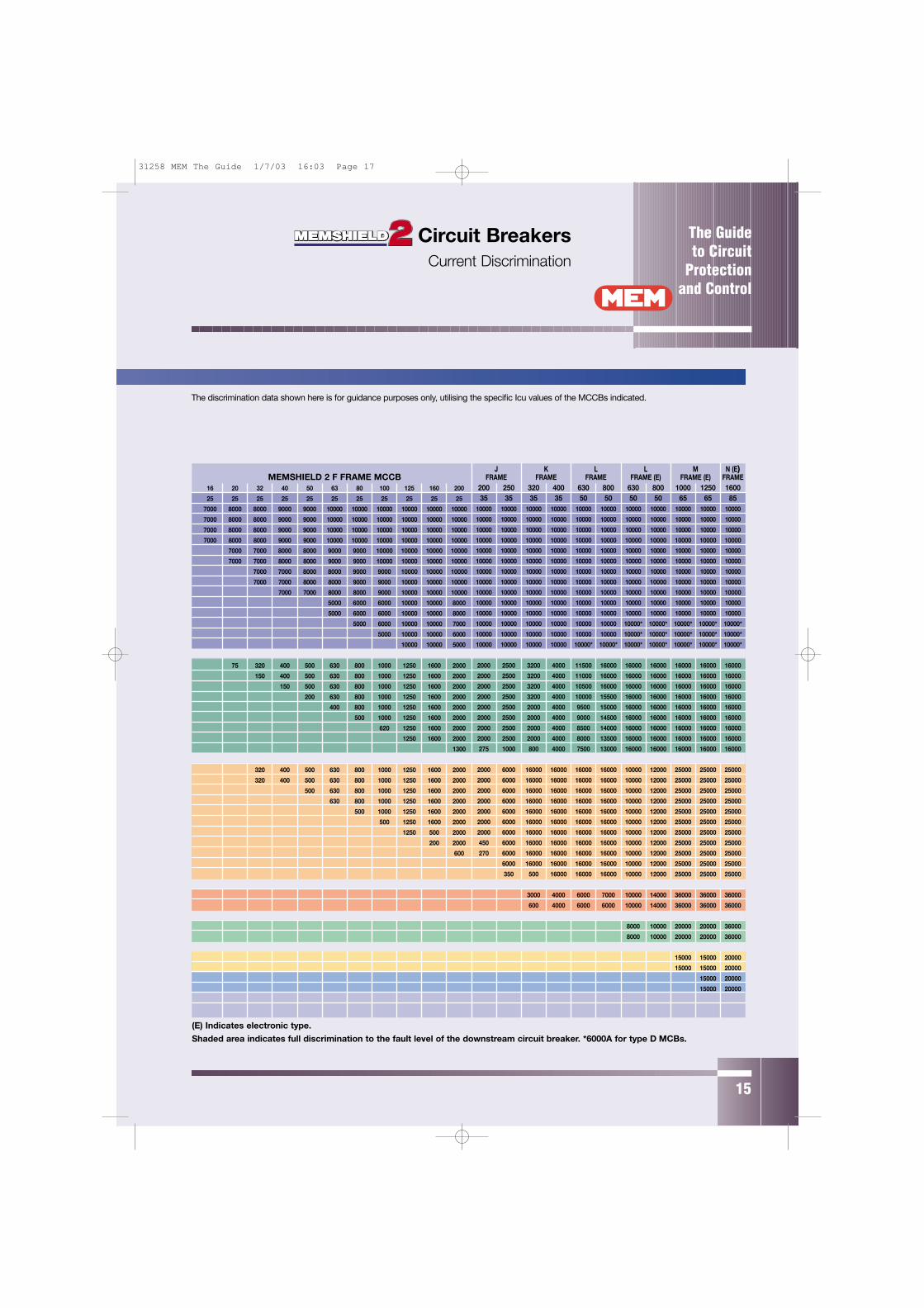
(E) Indicates electronic type.
Shaded area indicates full discrimination to the fault level of the downstream circuit breaker. *6000A for type D MCBs.
The discrimination data shown here is for guidance purposes only, utilising the specific Icu values of the MCCBs indicated.
J K L L M N (E)FRAME FRAME FRAME FRAME (E) FRAME (E) FRAME
200 250 320 400 630 800 630 800 1000 1250 160035 35 35 35 50 50 50 50 65 65 85
10000 10000 10000 10000 10000 10000 10000 10000 10000 10000 10000
10000 10000 10000 10000 10000 10000 10000 10000 10000 10000 10000
10000 10000 10000 10000 10000 10000 10000 10000 10000 10000 10000
10000 10000 10000 10000 10000 10000 10000 10000 10000 10000 10000
10000 10000 10000 10000 10000 10000 10000 10000 10000 10000 10000
10000 10000 10000 10000 10000 10000 10000 10000 10000 10000 10000
10000 10000 10000 10000 10000 10000 10000 10000 10000 10000 10000
10000 10000 10000 10000 10000 10000 10000 10000 10000 10000 10000
10000 10000 10000 10000 10000 10000 10000 10000 10000 10000 10000
10000 10000 10000 10000 10000 10000 10000 10000 10000 10000 10000
10000 10000 10000 10000 10000 10000 10000 10000 10000 10000 10000
10000 10000 10000 10000 10000 10000 10000* 10000* 10000* 10000* 10000*
10000 10000 10000 10000 10000 10000 10000* 10000* 10000* 10000* 10000*
10000 10000 10000 10000 10000* 10000* 10000* 10000* 10000* 10000* 10000*
2000 2500 3200 4000 11500 16000 16000 16000 16000 16000 16000
2000 2500 3200 4000 11000 16000 16000 16000 16000 16000 16000
2000 2500 3200 4000 10500 16000 16000 16000 16000 16000 16000
2000 2500 3200 4000 10000 15500 16000 16000 16000 16000 16000
2000 2500 2000 4000 9500 15000 16000 16000 16000 16000 16000
2000 2500 2000 4000 9000 14500 16000 16000 16000 16000 16000
2000 2500 2000 4000 8500 14000 16000 16000 16000 16000 16000
2000 2500 2000 4000 8000 13500 16000 16000 16000 16000 16000
275 1000 800 4000 7500 13000 16000 16000 16000 16000 16000
2000 6000 16000 16000 16000 16000 10000 12000 25000 25000 25000
2000 6000 16000 16000 16000 16000 10000 12000 25000 25000 25000
2000 6000 16000 16000 16000 16000 10000 12000 25000 25000 25000
2000 6000 16000 16000 16000 16000 10000 12000 25000 25000 25000
2000 6000 16000 16000 16000 16000 10000 12000 25000 25000 25000
2000 6000 16000 16000 16000 16000 10000 12000 25000 25000 25000
2000 6000 16000 16000 16000 16000 10000 12000 25000 25000 25000
450 6000 16000 16000 16000 16000 10000 12000 25000 25000 25000
270 6000 16000 16000 16000 16000 10000 12000 25000 25000 25000
6000 16000 16000 16000 16000 10000 12000 25000 25000 25000
350 500 16000 16000 16000 10000 12000 25000 25000 25000
3000 4000 6000 7000 10000 14000 36000 36000 36000
600 4000 6000 6000 10000 14000 36000 36000 36000
8000 10000 20000 20000 36000
8000 10000 20000 20000 36000
15000 15000 20000
15000 15000 20000
15000 20000
15000 20000
MEMSHIELD 2 F FRAME MCCB16 20 32 40 50 63 80 100 125 160 200
25 25 25 25 25 25 25 25 25 25 25
7000 8000 8000 9000 9000 10000 10000 10000 10000 10000 10000
7000 8000 8000 9000 9000 10000 10000 10000 10000 10000 10000
7000 8000 8000 9000 9000 10000 10000 10000 10000 10000 10000
7000 8000 8000 9000 9000 10000 10000 10000 10000 10000 10000
7000 7000 8000 8000 9000 9000 10000 10000 10000 10000
7000 7000 8000 8000 9000 9000 10000 10000 10000 10000
7000 7000 8000 8000 9000 9000 10000 10000 10000
7000 7000 8000 8000 9000 9000 10000 10000 10000
7000 7000 8000 8000 9000 10000 10000 10000
5000 6000 6000 10000 10000 8000
5000 6000 6000 10000 10000 8000
5000 6000 10000 10000 7000
5000 10000 10000 6000
10000 10000 5000
75 320 400 500 630 800 1000 1250 1600 2000
150 400 500 630 800 1000 1250 1600 2000
150 500 630 800 1000 1250 1600 2000
200 630 800 1000 1250 1600 2000
400 800 1000 1250 1600 2000
500 1000 1250 1600 2000
620 1250 1600 2000
1250 1600 2000
1300
320 400 500 630 800 1000 1250 1600 2000
320 400 500 630 800 1000 1250 1600 2000
500 630 800 1000 1250 1600 2000
630 800 1000 1250 1600 2000
500 1000 1250 1600 2000
500 1250 1600 2000
1250 500 2000
200 2000
600
Circuit Breakers Current Discrimination
31258 MEM The Guide 1/7/03 16:03 Page 17
The Guide to CircuitProtectionand Control
16
DO
WN
ST
RE
AM
UPSTREAM
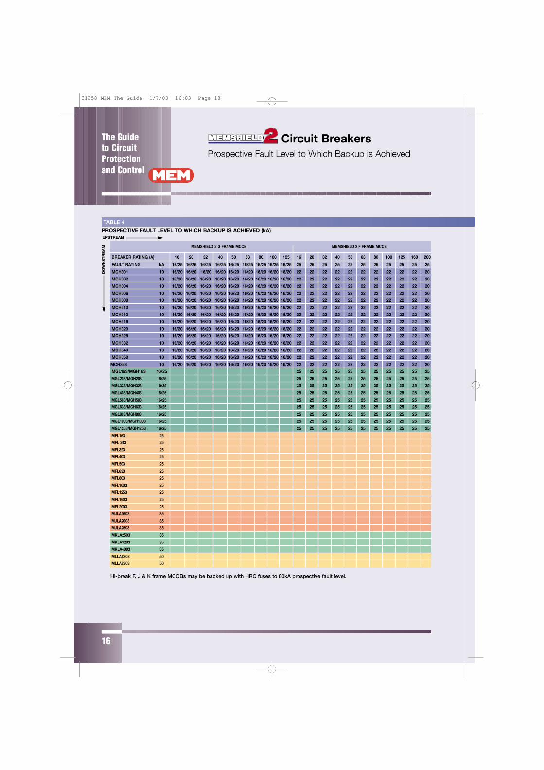
TABLE 4
PROSPECTIVE FAULT LEVEL TO WHICH BACKUP IS ACHIEVED (kA)
MEMSHIELD 2 G FRAME MCCB
BREAKER RATING (A) 16 20 32 40 50 63 80 100
FAULT RATING kA 16/25 16/25 16/25 16/25 16/25 16/25 16/25 16/25
MCH301 10 16/20 16/20 16/20 16/20 16/20 16/20 16/20 16/20
MCH302 10 16/20 16/20 16/20 16/20 16/20 16/20 16/20 16/20
MCH304 10 16/20 16/20 16/20 16/20 16/20 16/20 16/20 16/20
MCH306 10 16/20 16/20 16/20 16/20 16/20 16/20 16/20 16/20
MCH308 10 16/20 16/20 16/20 16/20 16/20 16/20 16/20 16/20
MCH310 10 16/20 16/20 16/20 16/20 16/20 16/20 16/20 16/20
MCH313 10 16/20 16/20 16/20 16/20 16/20 16/20 16/20 16/20
MCH316 10 16/20 16/20 16/20 16/20 16/20 16/20 16/20 16/20
MCH320 10 16/20 16/20 16/20 16/20 16/20 16/20 16/20 16/20
MCH325 10 16/20 16/20 16/20 16/20 16/20 16/20 16/20 16/20
MCH332 10 16/20 16/20 16/20 16/20 16/20 16/20 16/20 16/20
MCH340 10 16/20 16/20 16/20 16/20 16/20 16/20 16/20 16/20
MCH350 10 16/20 16/20 16/20 16/20 16/20 16/20 16/20 16/20
MCH363 10 16/20 16/20 16/20 16/20 16/20 16/20 16/20 16/20
MGL163/MGH163 16/25
MGL203/MGH203 16/25
MGL323/MGH323 16/25
MGL403/MGH403 16/25
MGL503/MGH503 16/25
MGL633/MGH633 16/25
MGL803/MGH803 16/25
MGL1003/MGH1003 16/25
MGL1253/MGH1253 16/25
MFL163 25
MFL 203 25
MFL323 25
MFL403 25
MFL503 25
MFL633 25
MFL803 25
MFL1003 25
MFL1253 25
MFL1603 25
MFL2003 25
MJLA1603 35
MJLA2003 35
MJLA2503 35
MKLA2503 35
MKLA3203 35
MKLA4003 35
MLLA6303 50
MLLA8303 50
MEMSHIELD 2 F FRAME MCCB
125 16 20 32 40 50 63 80 100 125 160 200
16/25 25 25 25 25 25 25 25 25 25 25 25
16/20 22 22 22 22 22 22 22 22 22 22 20
16/20 22 22 22 22 22 22 22 22 22 22 20
16/20 22 22 22 22 22 22 22 22 22 22 20
16/20 22 22 22 22 22 22 22 22 22 22 20
16/20 22 22 22 22 22 22 22 22 22 22 20
16/20 22 22 22 22 22 22 22 22 22 22 20
16/20 22 22 22 22 22 22 22 22 22 22 20
16/20 22 22 22 22 22 22 22 22 22 22 20
16/20 22 22 22 22 22 22 22 22 22 22 20
16/20 22 22 22 22 22 22 22 22 22 22 20
16/20 22 22 22 22 22 22 22 22 22 22 20
16/20 22 22 22 22 22 22 22 22 22 22 20
16/20 22 22 22 22 22 22 22 22 22 22 20
16/20 22 22 22 22 22 22 22 22 22 22 20
25 25 25 25 25 25 25 25 25 25 25
25 25 25 25 25 25 25 25 25 25 25
25 25 25 25 25 25 25 25 25 25 25
25 25 25 25 25 25 25 25 25 25 25
25 25 25 25 25 25 25 25 25 25 25
25 25 25 25 25 25 25 25 25 25 25
25 25 25 25 25 25 25 25 25 25 25
25 25 25 25 25 25 25 25 25 25 25
25 25 25 25 25 25 25 25 25 25 25
Circuit Breakers Prospective Fault Level to Which Backup is Achieved
Hi-break F, J & K frame MCCBs may be backed up with HRC fuses to 80kA prospective fault level.
31258 MEM The Guide 1/7/03 16:03 Page 18

The Guide to Circuit
Protectionand Control
17
(E) Indicates electronic Type
J FRAME K FRAME L FRAME M FRAME (E) N FRAME BS88 MAX FUSE BS1361(E) MAX FUSE
160 200 250 320 400 630 800 1000 1250 1600 100 160 200 400 450 100
36 36 36 36 36 50 50 65 65 85 80 80 80 80 80 33
20 20 20 40 25 25 33
20 20 20 40 25 25 33
20 20 20 40 25 25 33
20 20 20 40 25 25 33
20 20 20 40 25 25 33
20 20 20 40 25 25 33
20 20 20 40 25 25 33
20 20 20 50 40 25 33
20 20 20 50 40 25 33
20 20 20 50 40 25 33
20 20 20 50 40 25 33
20 20 20 50 40 25 33
20 20 20 50 40 33
20 20 20 50 40 33
36 36 36 36 36 80 80 80 80
36 36 36 36 36 80 80 80 80
36 36 36 36 36 80 80 80
36 36 36 36 36 80 80 80 80
36 36 36 36 36 80 80 80 80
36 36 36 36 36 80 80 80 80
35 35 35 35 36 80 80 80
36 36 36 36 36 80 80 80
36 36 36 36 36 80 80 80
36 36 36 36 36 50 50 80 80 80 80
36 36 36 36 36 50 50 80 80 80 80
36 36 36 36 36 50 50 80 80 80 80
36 36 36 36 36 50 50 80 80 80 80
36 36 36 36 36 50 50 80 80 80 80 80
36 36 36 36 36 50 50 80 80 80 80 80
36 36 36 36 36 50 50 80 80 80 80 80
36 36 36 36 36 50 50 80 80 80 80 80
36 36 36 36 36 50 50 80 80 80 80
36 36 36 36 50 50 80 80 80 80
36 36 36 50 50 80 80 80
36 36 36 50 50 80 80 80
36 36 36 50 50 80 80 80
36 36 36 50 50 80 80
36 36 50 50 80 80
36 50 50 80 80
50 50 80 80
65 85
65 85
Circuit BreakersProspective Fault Level to Which Backup is Achieved
31258 MEM The Guide 1/7/03 16:03 Page 19
The Guide to CircuitProtectionand Control
18
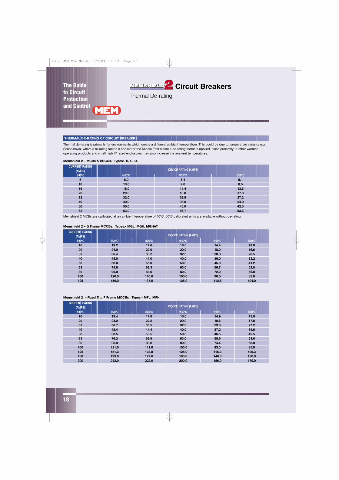
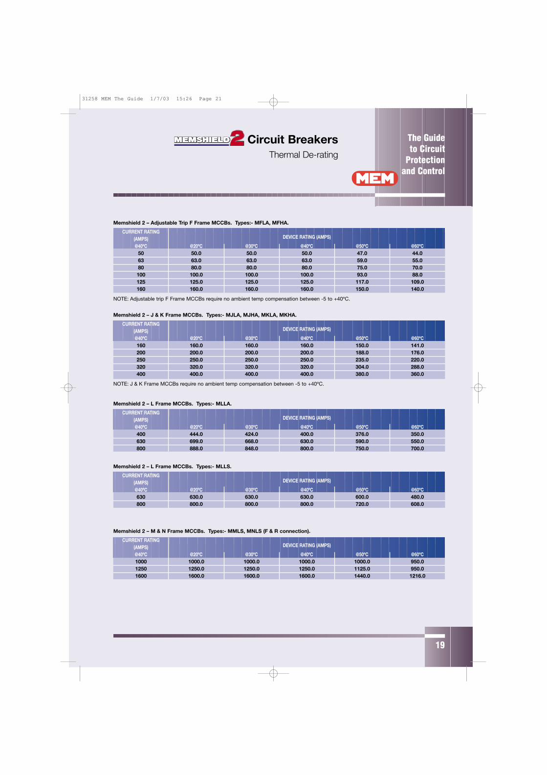
THERMAL DE-RATING OF CIRCUIT BREAKERS
Thermal de-rating is primarily for environments which create a different ambient temperature. This could be due to temperature variants e.g.Scandinavia, where a re-rating factor is applied or the Middle East where a de-rating factor is applied, close proximity to other warmeroperating products and small high IP rated enclosures may also increase the ambient temperatures.
Memshield 2 – MCBs & RBCOs. Types:- B, C, D.
CURRENT RATINGDEVICE RATING (AMPS)(AMPS)
@40ºC @40ºC @55ºC @60ºC6 6.0 5.4 5.110 10.0 9.0 8.516 16.0 14.4 13.620 20.0 18.0 17.032 32.0 28.8 27.240 40.0 36.0 34.050 50.0 45.0 42.563 63.0 56.7 53.6
Memshield 2 MCBs are calibrated at an ambient temperature of 40ºC. 50ºC calibrated units are available without de-rating.
Memshield 2 – G Frame MCCBs. Types:- MGL, MGH, MGHAT.
CURRENT RATINGDEVICE RATING (AMPS)(AMPS)
@40ºC @20ºC @30ºC @40ºC @50ºC @60ºC16 19.2 17.6 16.0 14.4 13.020 24.0 22.0 20.0 18.0 16.632 38.4 35.2 32.0 28.8 26.540 48.0 44.0 40.0 36.0 33.250 60.0 55.0 50.0 45.0 41.263 75.6 69.3 63.0 56.7 52.080 96.0 88.0 80.0 72.0 66.0100 120.0 110.0 100.0 90.0 83.0125 150.0 137.5 125.0 112.5 104.0
Memshield 2 – Fixed Trip F Frame MCCBs. Types:- MFL, MFH.
CURRENT RATINGDEVICE RATING (AMPS)(AMPS)
@40ºC @20ºC @30ºC @40ºC @50ºC @60ºC16 19.4 17.8 16.0 14.9 13.620 24.2 22.2 20.0 18.6 17.032 38.7 35.5 32.0 29.8 27.240 48.4 44.4 40.0 37.2 34.050 60.5 55.5 50.0 46.5 42.563 76.2 69.9 63.0 58.6 53.680 96.8 88.8 80.0 74.4 68.0100 121.0 111.0 100.0 93.0 85.0125 151.3 138.8 125.0 116.3 106.3160 193.6 177.6 160.0 148.8 136.0200 242.0 222.0 200.0 186.0 170.0
Circuit Breakers Thermal De-rating
31258 MEM The Guide 1/7/03 16:17 Page 20
The Guide to Circuit
Protectionand Control
19
Memshield 2 – Adjustable Trip F Frame MCCBs. Types:- MFLA, MFHA.
CURRENT RATINGDEVICE RATING (AMPS)(AMPS)
@40ºC @20ºC @30ºC @40ºC @50ºC @60ºC50 50.0 50.0 50.0 47.0 44.063 63.0 63.0 63.0 59.0 55.080 80.0 80.0 80.0 75.0 70.0100 100.0 100.0 100.0 93.0 88.0125 125.0 125.0 125.0 117.0 109.0160 160.0 160.0 160.0 150.0 140.0
NOTE: Adjustable trip F Frame MCCBs require no ambient temp compensation between -5 to +40ºC.
Memshield 2 – J & K Frame MCCBs. Types:- MJLA, MJHA, MKLA, MKHA.
CURRENT RATINGDEVICE RATING (AMPS)(AMPS)
@40ºC @20ºC @30ºC @40ºC @50ºC @60ºC160 160.0 160.0 160.0 150.0 141.0200 200.0 200.0 200.0 188.0 176.0250 250.0 250.0 250.0 235.0 220.0320 320.0 320.0 320.0 304.0 288.0400 400.0 400.0 400.0 380.0 360.0
NOTE: J & K Frame MCCBs require no ambient temp compensation between -5 to +40ºC.
Memshield 2 – L Frame MCCBs. Types:- MLLA.
CURRENT RATINGDEVICE RATING (AMPS)(AMPS)
@40ºC @20ºC @30ºC @40ºC @50ºC @60ºC400 444.0 424.0 400.0 376.0 350.0630 699.0 668.0 630.0 590.0 550.0800 888.0 848.0 800.0 750.0 700.0
Memshield 2 – L Frame MCCBs. Types:- MLLS.
CURRENT RATINGDEVICE RATING (AMPS)(AMPS)
@40ºC @20ºC @30ºC @40ºC @50ºC @60ºC630 630.0 630.0 630.0 600.0 480.0800 800.0 800.0 800.0 720.0 608.0
Memshield 2 – M & N Frame MCCBs. Types:- MMLS, MNLS (F & R connection).
CURRENT RATINGDEVICE RATING (AMPS)(AMPS)
@40ºC @20ºC @30ºC @40ºC @50ºC @60ºC1000 1000.0 1000.0 1000.0 1000.0 950.01250 1250.0 1250.0 1250.0 1125.0 950.01600 1600.0 1600.0 1600.0 1440.0 1216.0
Circuit Breakers Thermal De-rating
31258 MEM The Guide 1/7/03 15:26 Page 21
The Guide to CircuitProtectionand Control
20
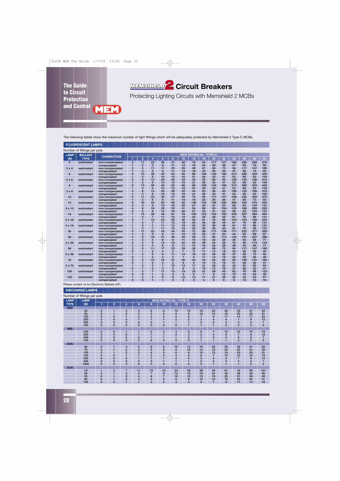
Circuit Breakers Protecting Lighting Circuits with Memshield 2 MCBs
The following tables show the maximum number of light fittings which will be adequately protected by Memshield 2 Type C MCBs.
FLUORESCENT LAMPS
Number of fittings per poleLAMP BALLAST CONNECTION
MCB RATING (A) - TYPE C(W) TYPE4 switchstart non-compensated
compensated2 x 4 switchstart non-compensated
compensated6 switchstart non-compensated
compensated2 x 6 switchstart non-compensated
compensated8 switchstart non-compensated
compensated2 x 8 switchstart non-compensated
compensated13 switchstart non-compensated
compensated15 switchstart non-compensated
compensated2 x 15 switchstart non-compensated
compensated18 switchstart non-compensated
compensated2 x 18 switchstart non-compensated
compensated4 x 18 switchstart non-compensated
compensated30 switchstart non-compensated
compensated36 switchstart non-compensated
compensated2 x 36 switchstart non-compensated
compensated58 switchstart non-compensated
compensated2 x 58 switchstart non-compensated
compensated70 switchstart non-compensated
compensated2 x 70 switchstart non-compensated
compensated100 switchstart non-compensated
compensated125 switchstart non-compensated
compensated
Please contact us for Electronic Ballasts (HF)
1 2 4 6 8 10 13 16 20 25 32 40 50 635 11 23 35 47 58 76 94 117 147 188 235 294 3701 2 5 8 11 14 19 23 29 36 47 58 73 922 5 11 17 23 29 38 47 58 73 94 117 147 1851 2 5 8 11 14 19 23 29 36 47 58 73 926 13 26 40 53 66 86 106 133 166 213 266 333 4201 3 6 10 13 16 21 26 33 41 53 66 83 1053 6 13 20 26 33 43 53 66 83 106 133 166 2101 3 6 10 13 16 21 26 33 41 53 66 83 1056 13 26 40 53 66 86 106 133 166 213 266 333 4201 3 6 10 13 16 21 26 33 41 53 66 83 1053 6 13 20 26 33 43 53 66 83 106 133 166 2101 3 6 10 13 16 21 26 33 41 53 66 83 1055 11 23 35 47 58 76 94 117 147 188 235 294 3701 2 5 8 11 14 19 23 29 36 47 58 73 928 16 33 50 66 83 108 133 166 208 266 333 416 5252 3 8 12 16 20 27 33 41 52 66 83 104 1314 8 16 25 33 41 54 66 83 104 133 166 208 2622 3 8 12 16 20 27 33 41 52 66 83 104 1317 15 30 46 61 76 100 123 153 192 246 307 384 4841 3 7 11 15 19 25 30 38 48 61 76 96 1213 7 15 23 30 38 50 61 76 96 123 153 192 2421 3 7 11 15 19 25 30 38 48 61 76 96 1211 3 7 11 15 19 25 30 38 48 61 76 96 1211 3 7 11 15 19 25 30 38 48 61 76 96 1215 11 22 33 44 55 72 88 111 138 177 222 277 3501 2 5 8 11 13 18 22 27 34 44 55 69 874 9 18 27 36 45 59 72 90 113 145 181 227 2861 2 4 6 9 11 14 18 22 28 36 45 56 712 4 9 13 18 22 29 36 45 56 72 90 113 1431 2 4 6 9 11 14 18 22 28 36 45 56 712 5 11 17 23 29 38 47 58 73 94 117 147 1850 1 2 4 5 7 9 11 14 18 23 29 36 461 2 5 8 11 14 19 23 29 36 47 58 73 920 1 2 4 5 7 9 11 14 18 23 29 36 462 5 10 15 21 26 34 42 52 65 84 105 131 1650 1 2 3 5 6 8 10 13 16 21 26 32 411 2 5 7 10 13 17 21 26 32 42 52 65 820 1 2 3 5 6 8 10 13 16 21 26 32 411 3 7 11 15 19 25 31 39 49 62 78 98 1230 0 1 2 3 4 6 7 9 12 15 19 24 301 2 4 6 8 10 13 17 21 26 34 42 53 670 0 1 1 2 2 3 4 5 6 8 10 13 16
DISCHARGE LAMPS
Number of fittings per poleLAMP LAMP MCB RATING (A) - TYPE CTYPE (W) 1 2 4 6 8 10 13 16 20 25 32 40 50 63MBF
50 0 1 3 5 6 8 10 13 16 20 26 33 41 5280 0 1 2 3 4 5 6 8 10 12 16 20 25 31125 0 0 1 2 2 3 4 5 7 8 11 14 17 22250 0 0 0 1 1 1 2 3 3 4 6 7 9 12400 0 0 0 0 0 1 1 1 2 2 3 4 5 7700 0 0 0 0 0 0 0 1 1 1 2 2 3 4
MBI150 0 0 1 1 2 3 4 5 6 7 10 12 15 19250 0 0 0 1 1 1 2 3 3 4 6 7 9 12400 0 0 0 0 1 1 1 2 2 3 4 5 6 7750 0 0 0 0 0 0 0 0 1 1 1 2 3 3
SON50 0 1 3 5 6 8 10 13 16 20 26 33 41 5270 0 1 2 3 5 6 8 10 12 15 20 25 31 39100 0 1 2 3 4 5 6 8 10 12 16 20 25 31150 0 0 1 1 2 3 4 5 6 7 10 12 15 19250 0 0 0 1 1 1 2 3 3 4 6 7 9 12400 0 0 0 0 0 1 1 1 2 2 3 4 5 71000 0 0 0 0 0 0 0 0 0 1 1 1 2 2
SOX18 1 3 7 11 15 19 24 30 38 48 61 76 96 12135 0 1 3 5 7 9 12 15 19 24 30 38 48 6055 0 1 3 4 6 7 10 12 15 19 25 31 39 4990 0 1 2 3 4 5 6 8 10 12 16 20 25 31135 0 0 1 1 2 2 3 4 5 7 9 11 14 18
31258 MEM The Guide 1/7/03 15:26 Page 22
The Guide to Circuit
Protectionand Control
21
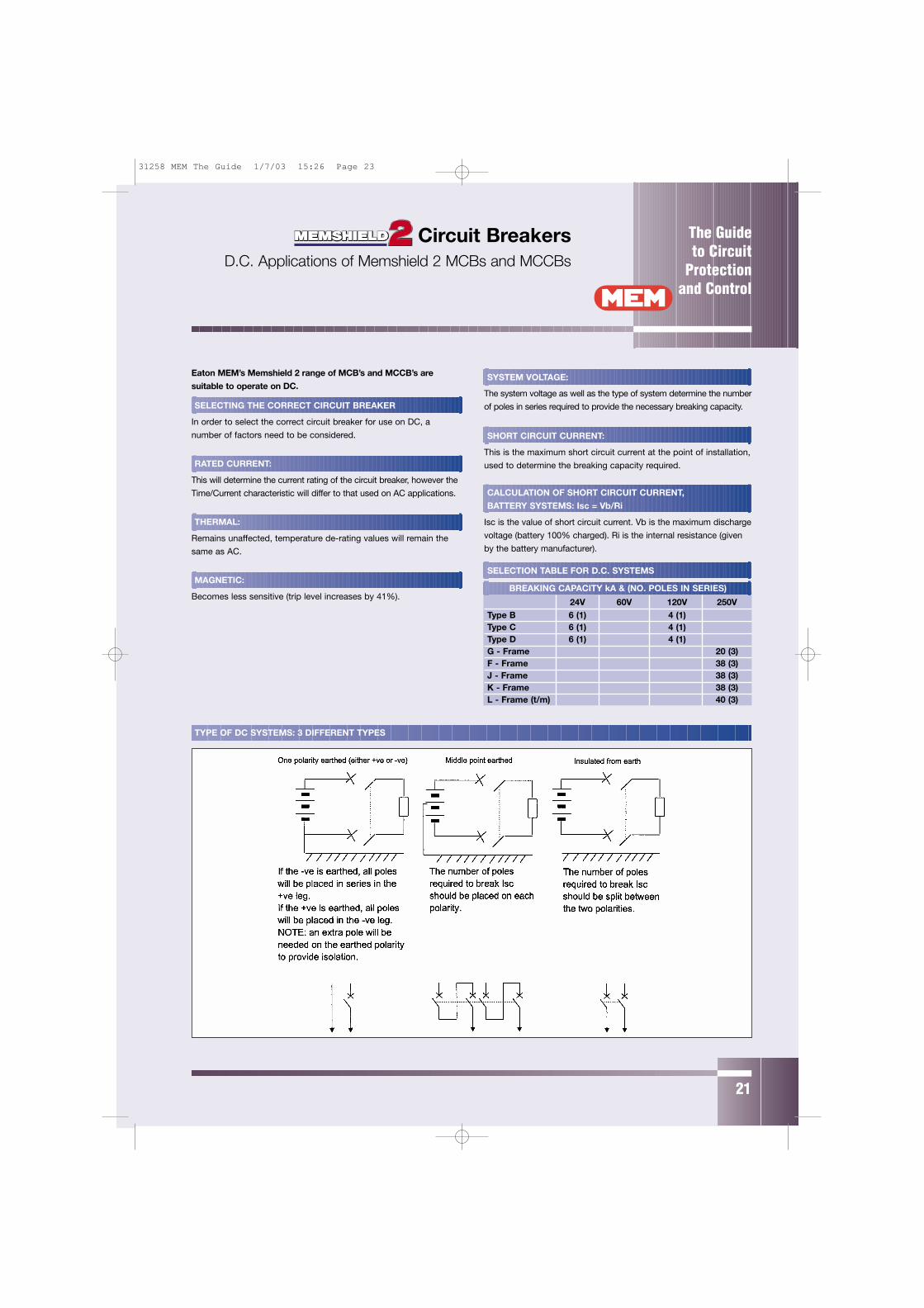
Eaton MEM’s Memshield 2 range of MCB’s and MCCB’s are
suitable to operate on DC.
SELECTING THE CORRECT CIRCUIT BREAKER
In order to select the correct circuit breaker for use on DC, a
number of factors need to be considered.
RATED CURRENT:
This will determine the current rating of the circuit breaker, however the
Time/Current characteristic will differ to that used on AC applications.
THERMAL:
Remains unaffected, temperature de-rating values will remain the
same as AC.
MAGNETIC:
Becomes less sensitive (trip level increases by 41%).
SYSTEM VOLTAGE:
The system voltage as well as the type of system determine the number
of poles in series required to provide the necessary breaking capacity.
SHORT CIRCUIT CURRENT:
This is the maximum short circuit current at the point of installation,
used to determine the breaking capacity required.
CALCULATION OF SHORT CIRCUIT CURRENT,
BATTERY SYSTEMS: Isc = Vb/Ri
Isc is the value of short circuit current. Vb is the maximum discharge
voltage (battery 100% charged). Ri is the internal resistance (given
by the battery manufacturer).
SELECTION TABLE FOR D.C. SYSTEMS
BREAKING CAPACITY kA & (NO. POLES IN SERIES)
24V 60V 120V 250VType B 6 (1) 4 (1)Type C 6 (1) 4 (1)Type D 6 (1) 4 (1)G - Frame 20 (3)F - Frame 38 (3)J - Frame 38 (3)K - Frame 38 (3)L - Frame (t/m) 40 (3)
TYPE OF DC SYSTEMS: 3 DIFFERENT TYPES
Circuit Breakers D.C. Applications of Memshield 2 MCBs and MCCBs
31258 MEM The Guide 1/7/03 15:26 Page 23
The Guide to CircuitProtectionand Control
22
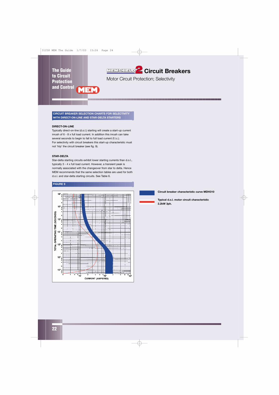
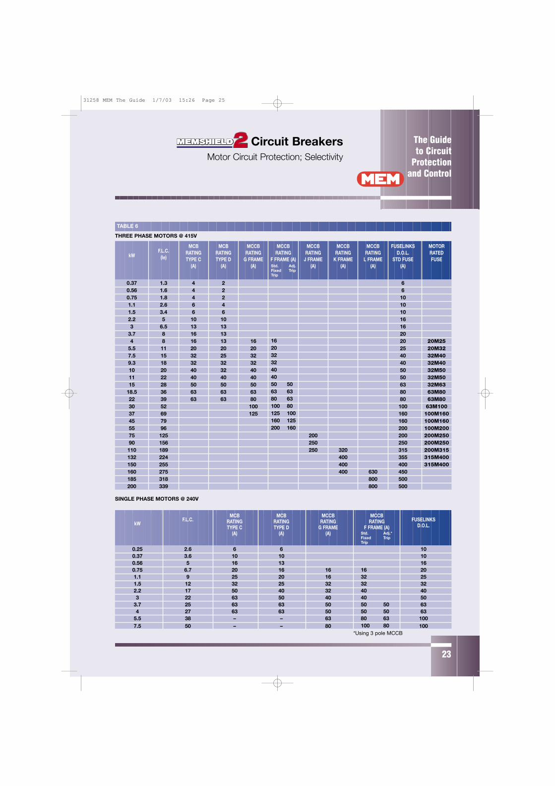
CIRCUIT BREAKER SELECTION CHARTS FOR SELECTIVITY
WITH DIRECT-ON-LINE AND STAR-DELTA STARTERS
DIRECT-ON-LINE
Typically direct-on-line (d.o.l.) starting will create a start-up current
inrush of 6 - 8 x full load current. In addition this inrush can take
several seconds to begin to fall to full load current (f.l.c.).
For selectivity with circuit breakers this start-up characteristic must
not ‘trip’ the circuit breaker (see fig. 9).
STAR-DELTA
Star-delta starting circuits exhibit lower starting currents than d.o.l.,
typically 3 - 4 x full load current. However, a transient peak is
normally associated with the changeover from star to delta. Hence
MEM recommends that the same selection tables are used for both
d.o.l. and star-delta starting circuits. See Table 6.
FIGURE 9
Circuit breaker characteristic curve MDH310
Typical d.o.l. motor circuit characteristic
2.2kW 3ph.
Circuit Breakers Motor Circuit Protection; Selectivity
31258 MEM The Guide 1/7/03 15:26 Page 24
The Guide to Circuit
Protectionand Control
23
TABLE 6
THREE PHASE MOTORS @ 415V
MCB MCB MCCB MCCB MCCB MCCB MCCB FUSELINKS MOTORF.L.C. RATING RATING RATING RATING RATING RATING RATING D.O.L. RATEDkW (le) TYPE C TYPE D G FRAME F FRAME (A) J FRAME K FRAME L FRAME STD FUSE FUSE
(A) (A) (A) (A) (A) (A) (A)
0.37 1.3 4 2 60.56 1.6 4 2 60.75 1.8 4 2 101.1 2.6 6 4 101.5 3.4 6 6 102.2 5 10 10 163 6.5 13 13 16
3.7 8 16 13 204 8 16 13 16 20 20M25
5.5 11 20 20 20 25 20M327.5 15 32 25 32 40 32M409.3 18 32 32 32 40 32M4010 20 40 32 40 50 32M5011 22 40 40 40 50 32M5015 28 50 50 50 63 32M63
18.5 36 63 63 63 80 63M8022 39 63 63 80 80 63M8030 52 100 100 63M10037 69 125 160 100M16045 79 160 100M16055 96 200 100M20075 125 200 200 200M25090 156 250 250 200M250110 189 250 320 315 200M315132 224 400 355 315M400150 255 400 400 315M400160 275 400 630 450185 318 800 500200 339 800 500
SINGLE PHASE MOTORS @ 240V
MCB MCB MCCB MCCBF.L.C. RATING RATING RATING RATING FUSELINKS
kWTYPE C TYPE D G FRAME F FRAME (A) D.O.L.
(A) (A) (A)
0.25 2.6 6 6 100.37 3.6 10 10 100.56 5 16 13 160.75 6.7 20 16 16 201.1 9 25 20 16 251.5 12 32 25 32 322.2 17 50 40 32 403 22 63 50 40 50
3.7 25 63 63 50 634 27 63 63 50 63
5.5 38 – – 63 1007.5 50 – – 80 100
Std. Adj.Fixed TripTrip
16203232404050 5063 6380 63100 80125 100160 125200 160
Std. Adj.*Fixed TripTrip
163232404050 5050 5080 63100 80
*Using 3 pole MCCB
Circuit Breakers Motor Circuit Protection; Selectivity
31258 MEM The Guide 1/7/03 15:26 Page 25

The Guide to CircuitProtectionand Control
24
32A Type B MCB (MBH132).
Typical 1000VA transformer curve 1ph.
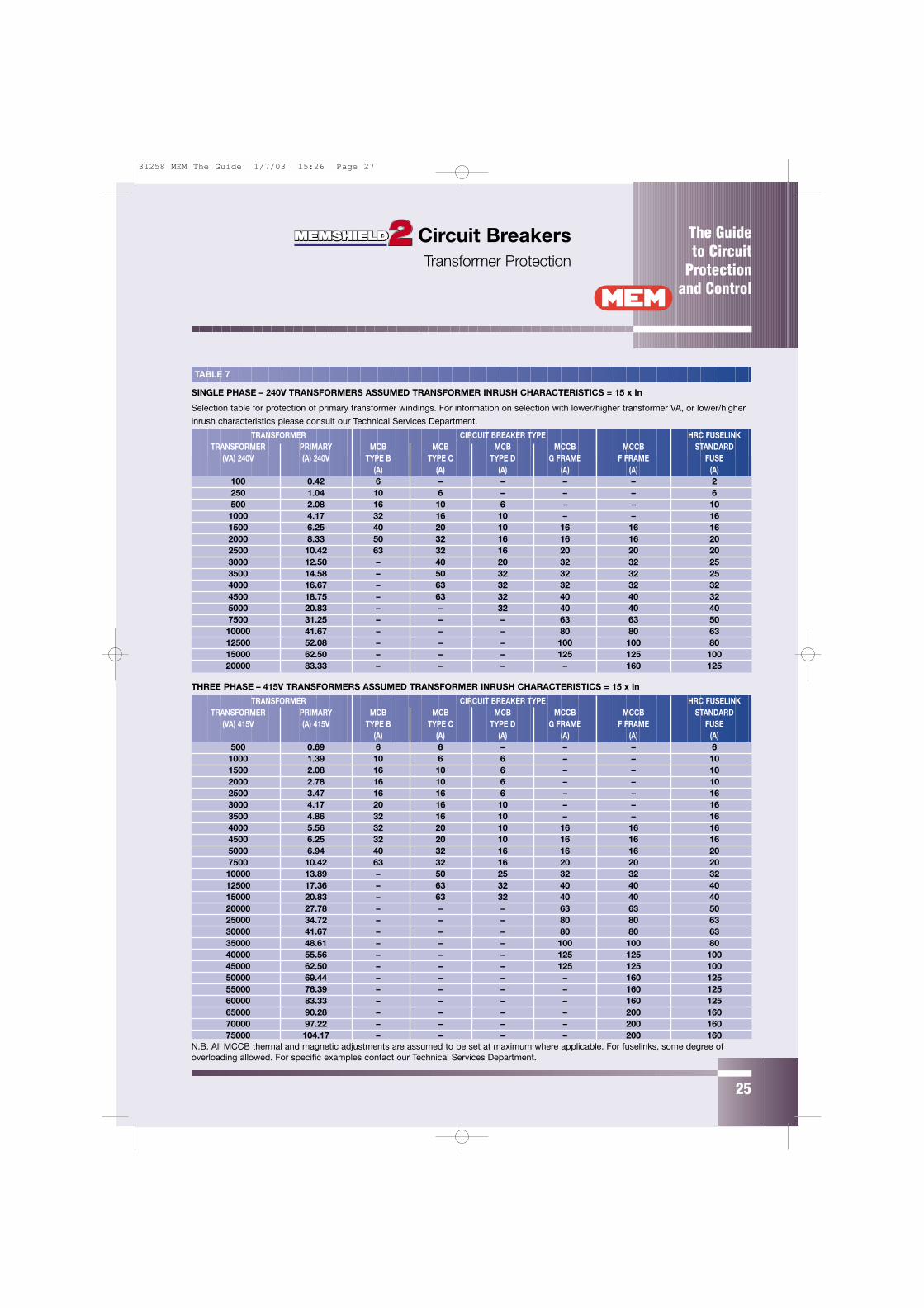
CIRCUIT BREAKER SELECTION CHARTS FOR CONNECTION
IN THE PRIMARY WINDINGS OF TRANSFORMERS.
Due to the inductive windings of transformers a high inrush current
is experienced upon ‘switch-on’. Typically this can be 10 - 15 x full
load current of the transformer (In) and is virtually instantaneous.
To protect supply lines to the primary windings of a transformer the
circuit breaker must provide thermal (long time) protection and
magnetic (short time) protection without the device tripping when
the transformer is switched on (see fig. 10).
FIGURE 10
Circuit Breakers Transformer Protection
31258 MEM The Guide 1/7/03 15:26 Page 26
The Guide to Circuit
Protectionand Control
25
TRANSFORMER CIRCUIT BREAKER TYPE HRC FUSELINKTRANSFORMER PRIMARY MCB MCB MCB MCCB MCCB STANDARD
(VA) 240V (A) 240V TYPE B TYPE C TYPE D G FRAME F FRAME FUSE(A) (A) (A) (A) (A) (A)
100 0.42 6 – – – – 2250 1.04 10 6 – – – 6500 2.08 16 10 6 – – 101000 4.17 32 16 10 – – 161500 6.25 40 20 10 16 16 162000 8.33 50 32 16 16 16 202500 10.42 63 32 16 20 20 203000 12.50 – 40 20 32 32 253500 14.58 – 50 32 32 32 254000 16.67 – 63 32 32 32 324500 18.75 – 63 32 40 40 325000 20.83 – – 32 40 40 407500 31.25 – – – 63 63 5010000 41.67 – – – 80 80 6312500 52.08 – – – 100 100 8015000 62.50 – – – 125 125 10020000 83.33 – – – – 160 125
THREE PHASE – 415V TRANSFORMERS ASSUMED TRANSFORMER INRUSH CHARACTERISTICS = 15 x In
TRANSFORMER CIRCUIT BREAKER TYPE HRC FUSELINKTRANSFORMER PRIMARY MCB MCB MCB MCCB MCCB STANDARD
(VA) 415V (A) 415V TYPE B TYPE C TYPE D G FRAME F FRAME FUSE(A) (A) (A) (A) (A) (A)
500 0.69 6 6 – – – 61000 1.39 10 6 6 – – 101500 2.08 16 10 6 – – 102000 2.78 16 10 6 – – 102500 3.47 16 16 6 – – 163000 4.17 20 16 10 – – 163500 4.86 32 16 10 – – 164000 5.56 32 20 10 16 16 164500 6.25 32 20 10 16 16 165000 6.94 40 32 16 16 16 207500 10.42 63 32 16 20 20 2010000 13.89 – 50 25 32 32 3212500 17.36 – 63 32 40 40 4015000 20.83 – 63 32 40 40 4020000 27.78 – – – 63 63 5025000 34.72 – – – 80 80 6330000 41.67 – – – 80 80 6335000 48.61 – – – 100 100 8040000 55.56 – – – 125 125 10045000 62.50 – – – 125 125 10050000 69.44 – – – – 160 12555000 76.39 – – – – 160 12560000 83.33 – – – – 160 12565000 90.28 – – – – 200 16070000 97.22 – – – – 200 16075000 104.17 – – – – 200 160
N.B. All MCCB thermal and magnetic adjustments are assumed to be set at maximum where applicable. For fuselinks, some degree ofoverloading allowed. For specific examples contact our Technical Services Department.
Selection table for protection of primary transformer windings. For information on selection with lower/higher transformer VA, or lower/higher
inrush characteristics please consult our Technical Services Department.
TABLE 7
SINGLE PHASE – 240V TRANSFORMERS ASSUMED TRANSFORMER INRUSH CHARACTERISTICS = 15 x In
Circuit Breakers Transformer Protection
31258 MEM The Guide 1/7/03 15:26 Page 27
26
WHAT DO THE ABBREVIATIONS MEAN?
R.C.D.: Residual Current Device is the generic term covering the
range of devices incorporating sensing of residual current and
includes within the scope R.C.C.B. and R.C.B.O. type products.
R.C.C.B.: Residual Current Circuit Breaker is an RCD which will
cause disconnection of electrical supply should a residual current
passing through the device exceed a specified level.
R.C.B.O.: Residual Current Circuit Breaker with Overload protection
is an RCD which will cause disconnection of electrical supply due to
residual current exceeding specified limits together with integral
overload; overcurrent and short circuit protection associated with a
miniature circuit breaker.
DEFINITIONS:
Residual Current: is the vector sum of the currents of all the phases
and associated neutral passing through the core balance
transformer of an RCD.
Equipotential Zone: the zone within which all conductive parts are
maintained at substantially the same potential by bonding to Earth.
WHEN MUST AN RCD BE USED?
BS7671 (16th Edition IEE Regs)
i) Sockets outlets on a TT supply (471-08-06)
ii) Sockets to supply portable equipment
outside the equipotential zone (471-16-01)
iii) Supply to caravan (608-13-05)
WHEN IS IT ADVISABLE TO INSTALL AN RCD?
For protection against risk of fire due to live to earth fault
where fault current is insufficient to cause over-current
protection device to operate.
For protection against risk of shock from indirect contact with
equipment suffering a live to earth fault.
For protection against shock in potentially
hazardous environment.
As supplementary protection against shock from directly
touching ‘Live’ parts.
Note: an RCD must not be used as the sole means of protection
against touching live parts.
WHAT TRIP CURRENT RATING SHOULD BE SELECTED?
10mA – to give a high degree of protection against electric shock in
a hazardous environment situation where supplementary protection
against shock from accidental direct contact is required.
This rating should only be used to supply final circuits where a high
risk exists.
30mA – to give a high degree of protection against electric shock in
a situation where supplementary protection against shock from
accidental direct contact is required when it must be able to trip
within 40 milliseconds when a fault current of 150mA is detected.
This will also satisfy the IEE/BS condition for supplementary
protection of sockets feeding portable equipment outside the
equipotential zone.
100mA – to give a degree of protection against electric shock due
to indirect contact situation.
Generally this rating should be used to protect groups of circuits
and provide overall protection against fire risk.
If lower rated RCD devices are employed down stream then a time
delayed 100mA RCD should be employed to ensure discrimination
between same.
300mA – gives overall protection against risk of fire from electrical
faults in wiring etc, only where sufficient current (typically less than
500mA) may cause incandescence of metal parts in suitable
circumstances and in consideration that installed over current
devices would require far in excess of 300mA to operate.
If lower rated RCD devices are employed down stream then a time
delayed 300mA RCD should be employed to ensure discrimination
between same.
NOTE: 10mA; 30mA and 100mA also inherently protect against
this risk.
Selection Criteria a
31258 MEM The Guide 1/7/03 15:27 Page 28
27
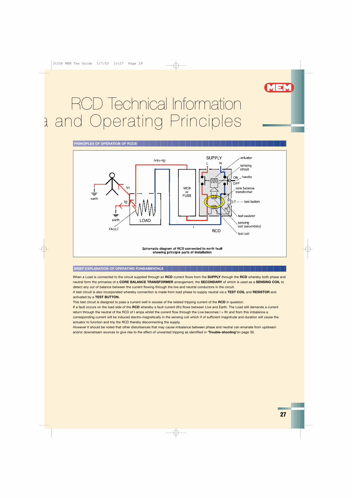
PRINCIPLES OF OPERATION OF RCCB
BRIEF EXPLANATION OF OPERATING FUNDAMENTALS
When a Load is connected to the circuit supplied through an RCD current flows from the SUPPLY through the RCD whereby both phase and
neutral form the primaries of a CORE BALANCE TRANSFORMER arrangement, the SECONDARY of which is used as a SENSING COIL to
detect any out of balance between the current flowing through the live and neutral conductors in the circuit.
A test circuit is also incorporated whereby connection is made from load phase to supply neutral via a TEST COIL and RESISTOR and
activated by a TEST BUTTON.
This test circuit is designed to pass a current well in excess of the related tripping current of the RCD in question.
If a fault occurs on the load side of the RCD whereby a fault current (lfn) flows between Live and Earth. The Load still demands a current
return through the neutral of the RCD of I amps whilst the current flow through the Live becomes l + lfn and from this imbalance a
corresponding current will be induced electro-magnetically in the sensing coil which if of sufficient magnitude and duration will cause the
actuator to function and trip the RCD thereby disconnecting the supply.
However it should be noted that other disturbances that may cause imbalance between phase and neutral can emanate from upstream
and/or downstream sources to give rise to the effect of unwanted tripping as identified in ‘Trouble-shooting’on page 30.
RCD Technical Informationa and Operating Principles
31258 MEM The Guide 1/7/03 15:27 Page 29
The Guide to CircuitProtectionand Control
28
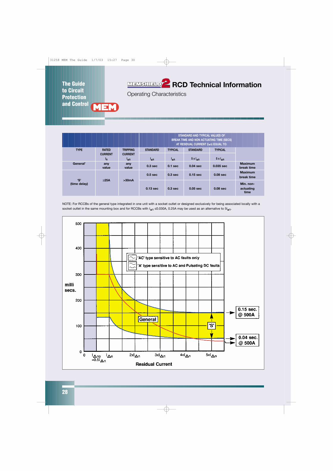
TYPE RATED TRIPPING STANDARD TYPICAL STANDARD TYPICALCURRENT CURRENT
ln ln ln ln 5 x ln 5 x lnGeneral’ any any
0.3 sec 0.1 sec 0.04 sec 0.035 secMaximum
value value break time
0.5 sec 0.3 sec 0.15 sec 0.08 secMaximum
break time‘S’ ≥25A >30mA
(time delay) Min. non-
0.13 sec 0.3 sec 0.05 sec 0.08 sec actuatingtime
NOTE: For RCCBs of the general type integrated in one unit with a socket outlet or designed exclusively for being associated locally with a
socket outlet in the same mounting box and for RCCBs with In ≤0.030A, 0.25A may be used as an alternative to 5ln.
STANDARD AND TYPICAL VALUES OFBREAK TIME AND NON ACTUATING TIME (SECS)
AT RESIDUAL CURRENT (In) EQUAL TO:
RCD Technical InformationOperating Characteristics
31258 MEM The Guide 1/7/03 15:27 Page 30
The Guide to Circuit
Protectionand Control
29
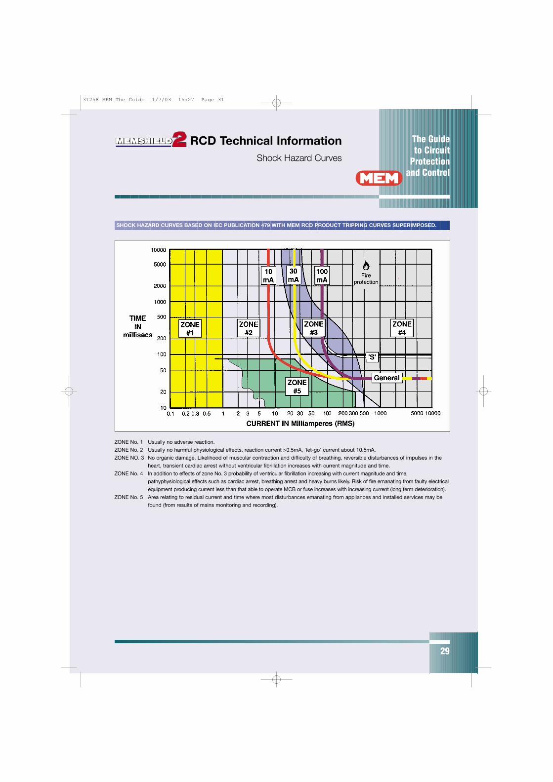
ZONE No. 1 Usually no adverse reaction.
ZONE No. 2 Usually no harmful physiological effects, reaction current >0.5mA, ‘let-go’ current about 10.5mA.
ZONE NO. 3 No organic damage. Likelihood of muscular contraction and difficulty of breathing, reversible disturbances of impulses in the
heart, transient cardiac arrest without ventricular fibrillation increases with current magnitude and time.
ZONE No. 4 In addition to effects of zone No. 3 probability of ventricular fibrillation increasing with current magnitude and time,
pathyphysiological effects such as cardiac arrest, breathing arrest and heavy burns likely. Risk of fire emanating from faulty electrical
equipment producing current less than that able to operate MCB or fuse increases with increasing current (long term deterioration).
ZONE No. 5 Area relating to residual current and time where most disturbances emanating from appliances and installed services may be
found (from results of mains monitoring and recording).
SHOCK HAZARD CURVES BASED ON IEC PUBLICATION 479 WITH MEM RCD PRODUCT TRIPPING CURVES SUPERIMPOSED.
RCD Technical InformationShock Hazard Curves
31258 MEM The Guide 1/7/03 15:27 Page 31
The Guide to CircuitProtectionand Control
30
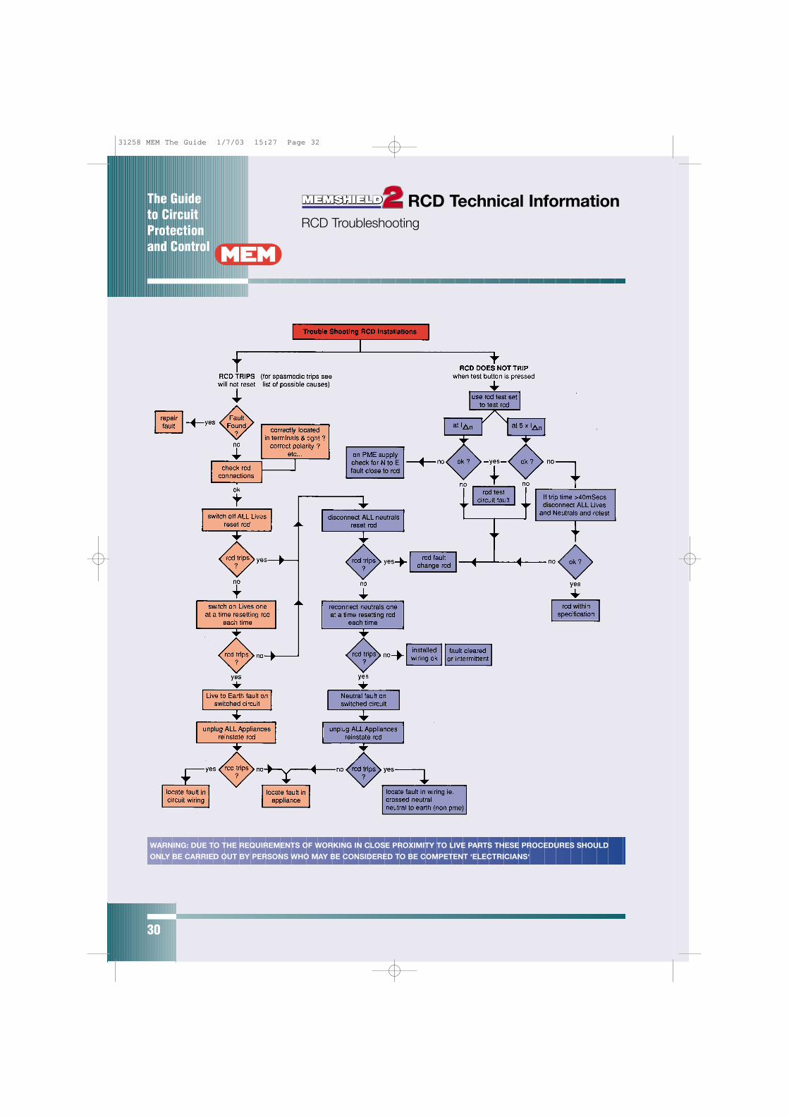
WARNING: DUE TO THE REQUIREMENTS OF WORKING IN CLOSE PROXIMITY TO LIVE PARTS THESE PROCEDURES SHOULD
ONLY BE CARRIED OUT BY PERSONS WHO MAY BE CONSIDERED TO BE COMPETENT ‘ELECTRICIANS‘
RCD Technical InformationRCD Troubleshooting
31258 MEM The Guide 1/7/03 15:27 Page 32
The Guide to Circuit
Protectionand Control
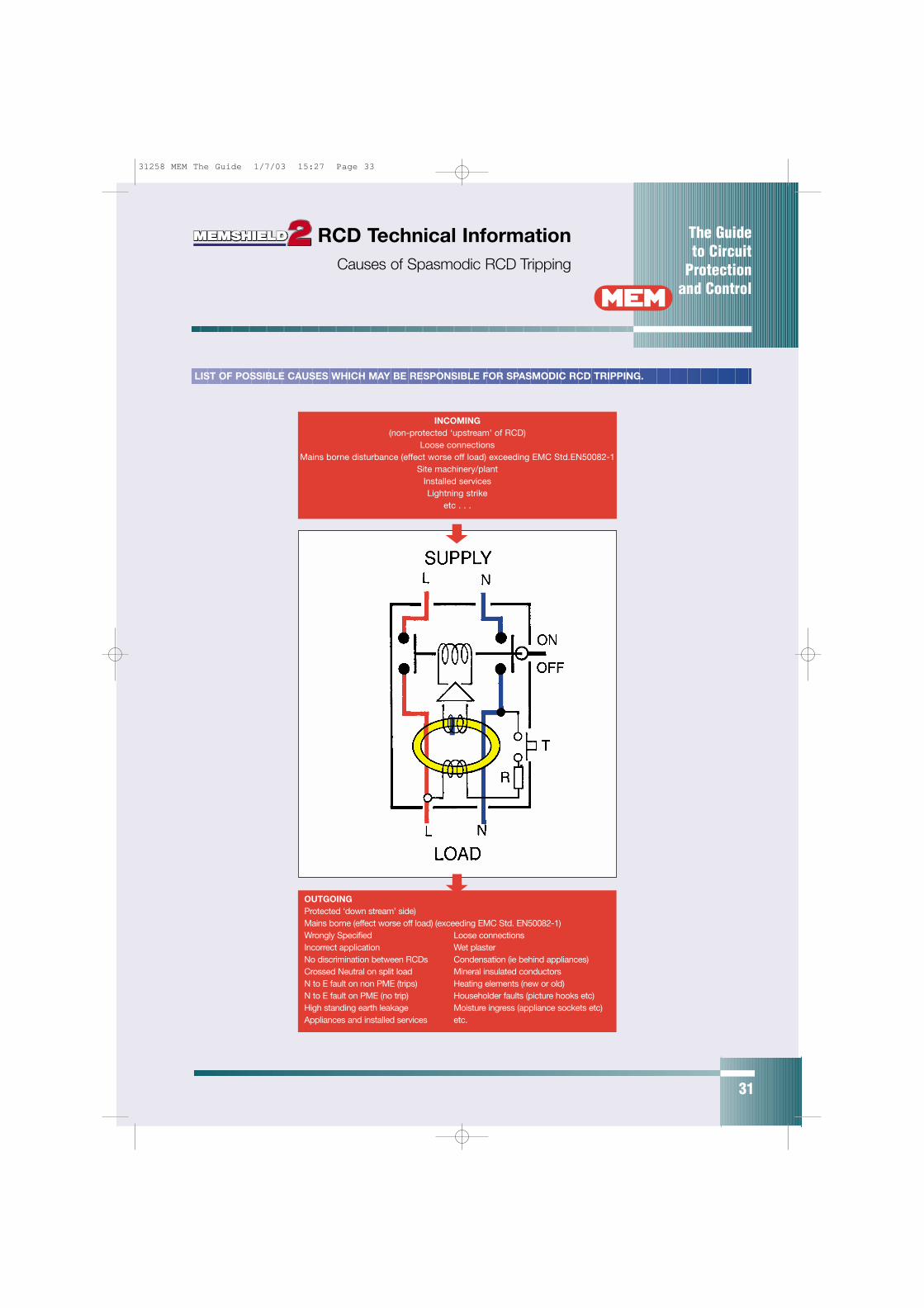
INCOMING(non-protected ‘upstream’ of RCD)
Loose connectionsMains borne disturbance (effect worse off load) exceeding EMC Std.EN50082-1
Site machinery/plantInstalled servicesLightning strike
etc . . .
LIST OF POSSIBLE CAUSES WHICH MAY BE RESPONSIBLE FOR SPASMODIC RCD TRIPPING.
OUTGOINGProtected ‘down stream’ side)Mains borne (effect worse off load) (exceeding EMC Std. EN50082-1)Wrongly Specified Loose connectionsIncorrect application Wet plasterNo discrimination between RCDs Condensation (ie behind appliances)Crossed Neutral on split load Mineral insulated conductorsN to E fault on non PME (trips) Heating elements (new or old)N to E fault on PME (no trip) Householder faults (picture hooks etc)High standing earth leakage Moisture ingress (appliance sockets etc)Appliances and installed services etc.
31
RCD Technical InformationCauses of Spasmodic RCD Tripping
31258 MEM The Guide 1/7/03 15:27 Page 33
The Guide to CircuitProtectionand Control
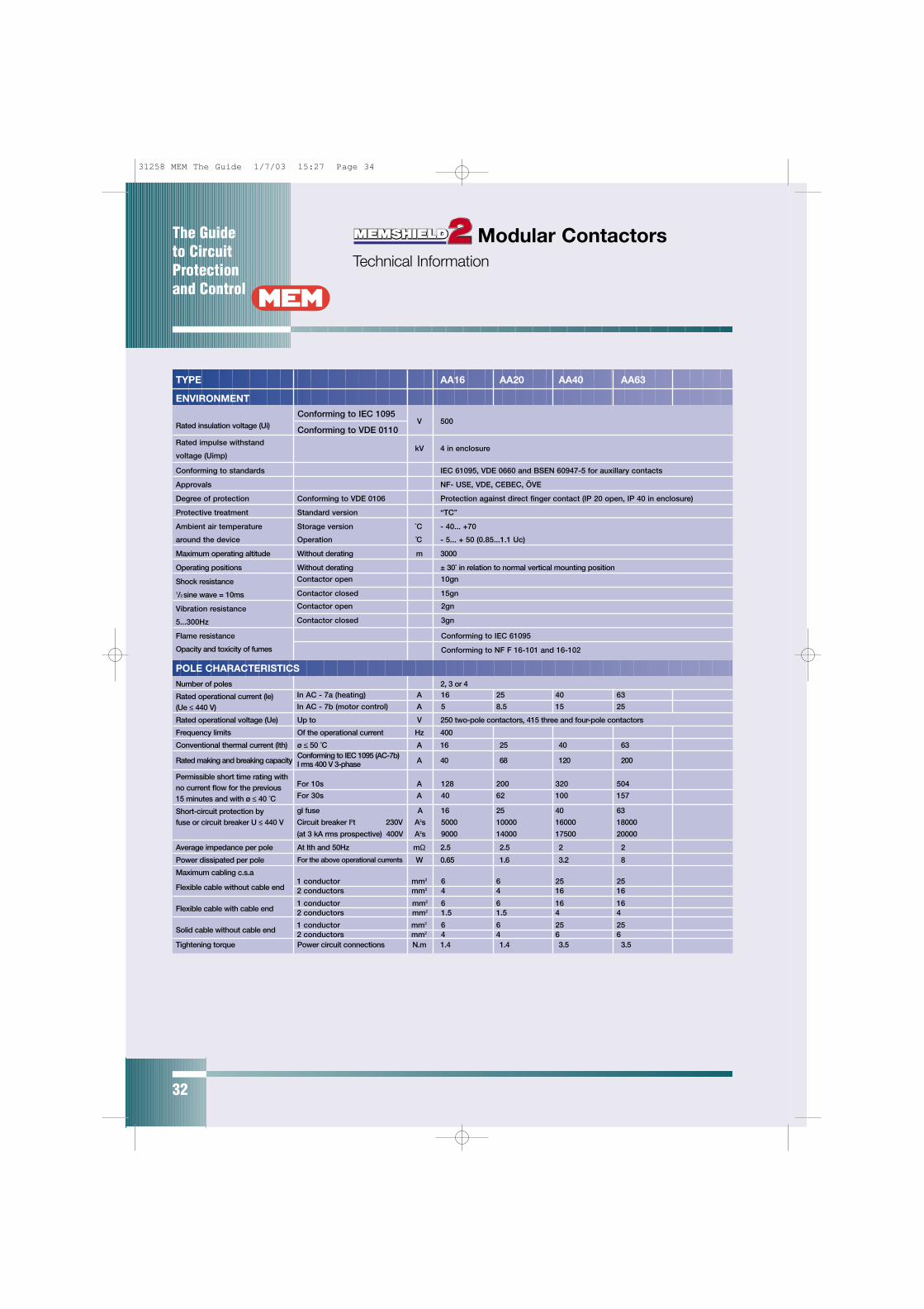
32
Conforming to IEC 1095
Conforming to VDE 0110
Contactor open 10gn
Contactor closed 15gn
Contactor open 2gn
Contactor closed 3gn
Conforming to IEC 61095
Conforming to NF F 16-101 and 16-102
TYPE AA16 AA20 AA40 AA63
ENVIRONMENT
Rated insulation voltage (Ui) V 500
Rated impulse withstandkV
voltage (Uimp)4 in enclosure
Conforming to standards IEC 61095, VDE 0660 and BSEN 60947-5 for auxillary contacts
Approvals NF- USE, VDE, CEBEC, ÖVE
Degree of protection Conforming to VDE 0106 Protection against direct finger contact (IP 20 open, IP 40 in enclosure)
Protective treatment Standard version “TC”
Ambient air temperature Storage version ˚C - 40... +70
around the device Operation ˚C - 5... + 50 (0.85...1.1 Uc)
Maximum operating altitude Without derating m 3000
Operating positions Without derating ± 30˚ in relation to normal vertical mounting position
Shock resistance1/2 sine wave = 10ms
Vibration resistance
5...300Hz
Flame resistance
Opacity and toxicity of fumes
POLE CHARACTERISTICS
Number of poles 2, 3 or 4
Rated operational current (le)(Ue ≤ 440 V)
Rated operational voltage (Ue) Up to V 250 two-pole contactors, 415 three and four-pole contactors
Frequency limits Of the operational current Hz 400
Conventional thermal current (lth) ø ≤ 50 ˚C A 16 25 40 63
Rated making and breaking capacityConforming to IEC 1095 (AC-7b)
A 40 68 120 200I rms 400 V 3-phase
Permissible short time rating with no current flow for the previous 15 minutes and with ø ≤ 40 ˚C
Short-circuit protection byfuse or circuit breaker U ≤ 440 V
Average impedance per pole At Ith and 50Hz mΩ 2.5 2.5 2 2
Power dissipated per pole For the above operational currents W 0.65 1.6 3.2 8
Maximum cabling c.s.a
Flexible cable without cable end
Flexible cable with cable end
Solid cable without cable end
Tightening torque Power circuit connections N.m 1.4 1.4 3.5 3.5
In AC - 7a (heating) A 16 25 40 63
In AC - 7b (motor control) A 5 8.5 15 25
1 conductor mm2 6 6 25 252 conductors mm2 4 4 16 16
1 conductor mm2 6 6 16 162 conductors mm2 1.5 1.5 4 4
1 conductor mm2 6 6 25 252 conductors mm2 4 4 6 6
For 10s A 128 200 320 504
For 30s A 40 62 100 157
gl fuse A 16 25 40 63
Circuit breaker I2t 230V A2s 5000 10000 16000 18000
(at 3 kA rms prospective) 400V A2s 9000 14000 17500 20000
Modular Contactors Technical Information
31258 MEM The Guide 1/7/03 15:27 Page 34
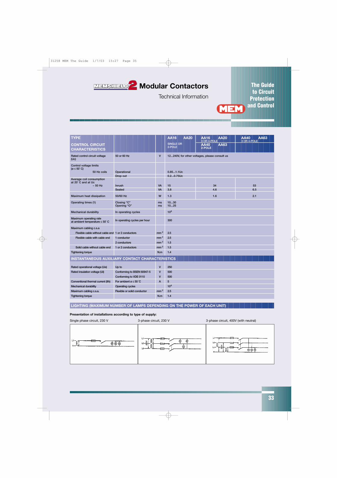
The Guide to Circuit
Protectionand Control
33
TYPE AA16 AA20
CONTROL CIRCUIT SINGLE OR
CHARACTERISTICS2-POLE
Rated control circuit voltage 50 or 60 Hz V 12...240V, for other voltages, please consult us(Uc)
Control voltage limits(ø ≤ 50˚ C)
50 Hz coils Operational 0.85...1.1UcDrop out 0.2...0.75Uc
Average coil consumptionat 20˚ C and at Uc
~ 50 Hz Inrush VA 15 34 53Sealed VA 3.8 4.6 6.5
Maximum heat dissipation 50/60 Hz W 1.3 1.6 2.1
Operating times (1) Closing “C” ms 10...30Opening “O” ms 10...25
Mechanical durability In operating cycles 106
Maximum operating rateat ambient temperature ≤ 50˚ C In operating cycles per hour 300
Maximum cabling c.s.a
Flexible cable without cable end 1 or 2 conductors mm 2 2.5
Flexible cable with cable end 1 conductor mm 2 2.5
2 conductors mm 2 1.5
Solid cable without cable end 1 or 2 conductors mm 2 1.5
Tightening torque N.m 1.4
INSTANTANEOUS AUXILIARY CONTACT CHARACTERISTICS
Rated operational voltage (Ue) Up to V 250
Rated insulation voltage (Ui) Conforming to BSEN 60947-5 V 500
Conforming to VDE 0110 V 500
Conventional thermal current (Ith) For ambient ø ≤ 50 ˚C A 5
Mechanical durability Operating cycles 106
Maximum cabling c.s.a. Flexible or solid conductor mm 2 2.5
Tightening torque N.m 1.4
AA16 AA203 OR 4-POLEAA40 AA632-POLE
AA40 AA633 OR 4-POLE
LIGHTING (MAXIMUM NUMBER OF LAMPS DEPENDING ON THE POWER OF EACH UNIT)
Presentation of installations according to type of supply:
Single phase circuit, 230 V 3-phase circuit, 230 V 3-phase circuit, 400V (with neutral)
Modular ContactorsTechnical Information
31258 MEM The Guide 1/7/03 15:27 Page 35
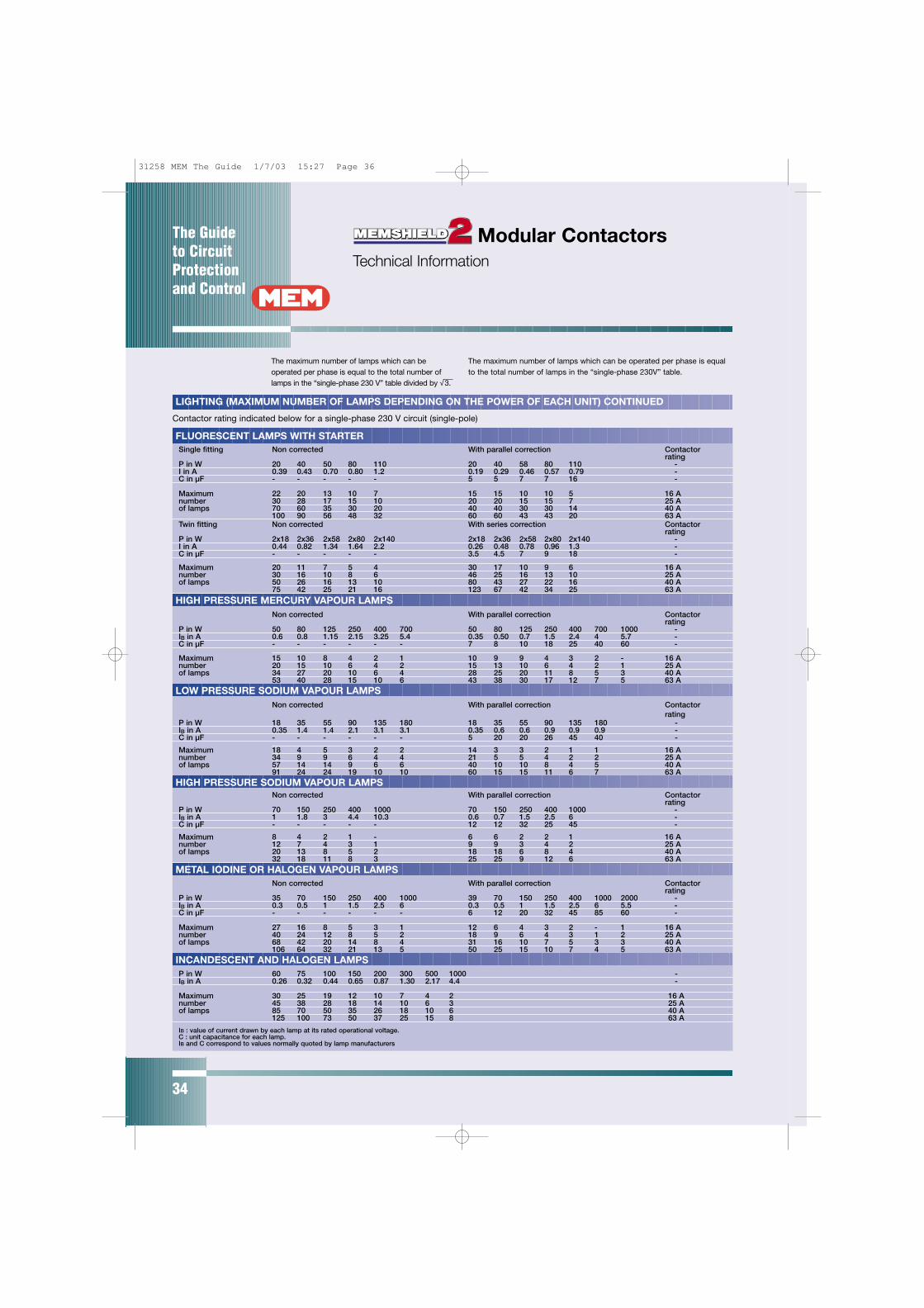
The Guide to CircuitProtectionand Control
34
FLUORESCENT LAMPS WITH STARTERSingle fitting Non corrected With parallel correction Contactor
ratingP in W 20 40 50 80 110 20 40 58 80 110 -I in A 0.39 0.43 0.70 0.80 1.2 0.19 0.29 0.46 0.57 0.79 -C in µF - - - - - 5 5 7 7 16 -
Maximum 22 20 13 10 7 15 15 10 10 5 16 Anumber 30 28 17 15 10 20 20 15 15 7 25 Aof lamps 70 60 35 30 20 40 40 30 30 14 40 A
100 90 56 48 32 60 60 43 43 20 63 ATwin fitting Non corrected With series correction Contactor
ratingP in W 2x18 2x36 2x58 2x80 2x140 2x18 2x36 2x58 2x80 2x140 -I in A 0.44 0.82 1.34 1.64 2.2 0.26 0.48 0.78 0.96 1.3 -C in µF - - - - - 3.5 4.5 7 9 18 -
Maximum 20 11 7 5 4 30 17 10 9 6 16 Anumber 30 16 10 8 6 46 25 16 13 10 25 Aof lamps 50 26 16 13 10 80 43 27 22 16 40 A
75 42 25 21 16 123 67 42 34 25 63 A
Non corrected With parallel correction Contactorrating
P in W 50 80 125 250 400 700 50 80 125 250 400 700 1000 -IB in A 0.6 0.8 1.15 2.15 3.25 5.4 0.35 0.50 0.7 1.5 2.4 4 5.7 -C in µF - - - - - - 7 8 10 18 25 40 60 -
Maximum 15 10 8 4 2 1 10 9 9 4 3 2 - 16 Anumber 20 15 10 6 4 2 15 13 10 6 4 2 1 25 Aof lamps 34 27 20 10 6 4 28 25 20 11 8 5 3 40 A
53 40 28 15 10 6 43 38 30 17 12 7 5 63 A
Non corrected With parallel correction Contactorrating
P in W 18 35 55 90 135 180 18 35 55 90 135 180 -IB in A 0.35 1.4 1.4 2.1 3.1 3.1 0.35 0.6 0.6 0.9 0.9 0.9 -C in µF - - - - - - 5 20 20 26 45 40 -
Maximum 18 4 5 3 2 2 14 3 3 2 1 1 16 Anumber 34 9 9 6 4 4 21 5 5 4 2 2 25 Aof lamps 57 14 14 9 6 6 40 10 10 8 4 5 40 A
91 24 24 19 10 10 60 15 15 11 6 7 63 A
Non corrected With parallel correction Contactorrating
P in W 70 150 250 400 1000 70 150 250 400 1000 -IB in A 1 1.8 3 4.4 10.3 0.6 0.7 1.5 2.5 6 -C in µF - - - - - 12 12 32 25 45 -
Maximum 8 4 2 1 - 6 6 2 2 1 16 Anumber 12 7 4 3 1 9 9 3 4 2 25 Aof lamps 20 13 8 5 2 18 18 6 8 4 40 A
32 18 11 8 3 25 25 9 12 6 63 A
Non corrected With parallel correction Contactorrating
P in W 35 70 150 250 400 1000 39 70 150 250 400 1000 2000 -IB in A 0.3 0.5 1 1.5 2.5 6 0.3 0.5 1 1.5 2.5 6 5.5 -C in µF - - - - - - 6 12 20 32 45 85 60 -
Maximum 27 16 8 5 3 1 12 6 4 3 2 - 1 16 Anumber 40 24 12 8 5 2 18 9 6 4 3 1 2 25 Aof lamps 68 42 20 14 8 4 31 16 10 7 5 3 3 40 A
106 64 32 21 13 5 50 25 15 10 7 4 5 63 A
P in W 60 75 100 150 200 300 500 1000 -IB in A 0.26 0.32 0.44 0.65 0.87 1.30 2.17 4.4 -
Maximum 30 25 19 12 10 7 4 2 16 Anumber 45 38 28 18 14 10 6 3 25 Aof lamps 85 70 50 35 26 18 10 6 40 A
125 100 73 50 37 25 15 8 63 A
IB : value of current drawn by each lamp at its rated operational voltage.C : unit capacitance for each lamp.IB and C correspond to values normally quoted by lamp manufacturers
HIGH PRESSURE MERCURY VAPOUR LAMPS
LOW PRESSURE SODIUM VAPOUR LAMPS
HIGH PRESSURE SODIUM VAPOUR LAMPS
METAL IODINE OR HALOGEN VAPOUR LAMPS
INCANDESCENT AND HALOGEN LAMPS
The maximum number of lamps which can beoperated per phase is equal to the total number oflamps in the “single-phase 230 V” table divided by √3.
The maximum number of lamps which can be operated per phase is equalto the total number of lamps in the “single-phase 230V” table.
Modular Contactors Technical Information
Contactor rating indicated below for a single-phase 230 V circuit (single-pole)
LIGHTING (MAXIMUM NUMBER OF LAMPS DEPENDING ON THE POWER OF EACH UNIT) CONTINUED
31258 MEM The Guide 1/7/03 15:27 Page 36
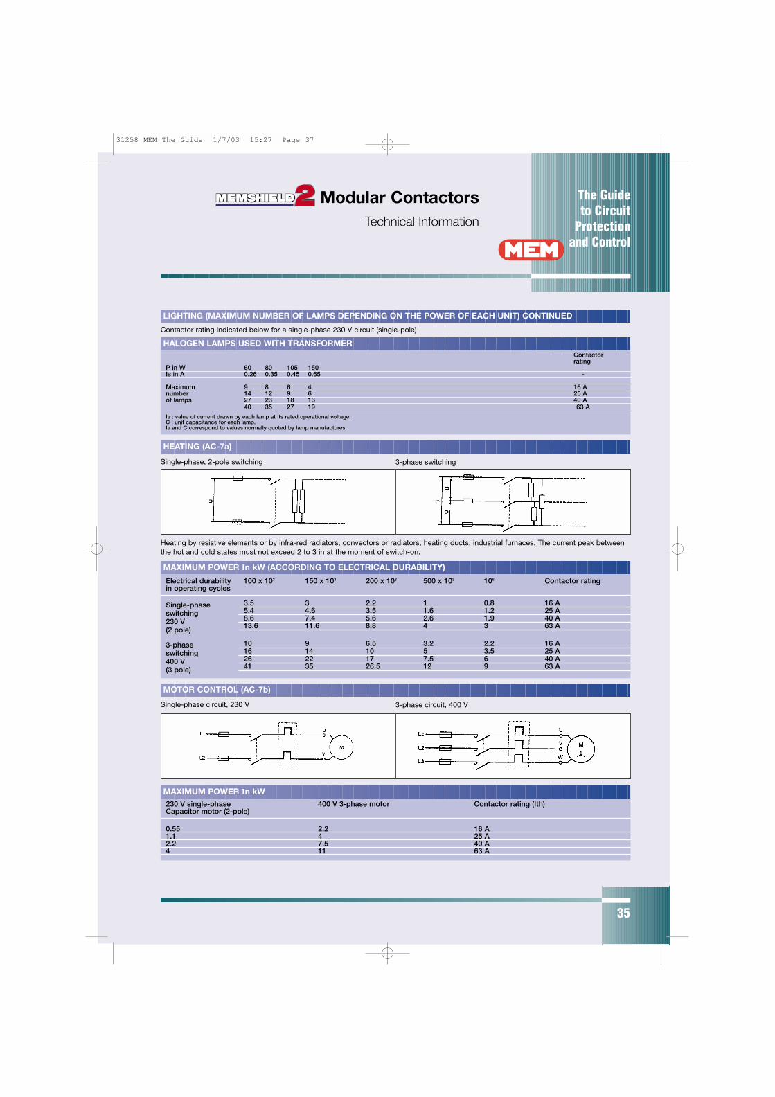
The Guide to Circuit
Protectionand Control
35
LIGHTING (MAXIMUM NUMBER OF LAMPS DEPENDING ON THE POWER OF EACH UNIT) CONTINUED
Contactor rating indicated below for a single-phase 230 V circuit (single-pole)
Contactorrating
P in W 60 80 105 150 -IB in A 0.26 0.35 0.45 0.65 -
Maximum 9 8 6 4 16 Anumber 14 12 9 6 25 Aof lamps 27 23 18 13 40 A
40 35 27 19 63 A
IB : value of current drawn by each lamp at its rated operational voltage.C : unit capacitance for each lamp.IB and C correspond to values normally quoted by lamp manufactures
HALOGEN LAMPS USED WITH TRANSFORMER
HEATING (AC-7a)
Single-phase, 2-pole switching 3-phase switching
Heating by resistive elements or by infra-red radiators, convectors or radiators, heating ducts, industrial furnaces. The current peak betweenthe hot and cold states must not exceed 2 to 3 in at the moment of switch-on.
MAXIMUM POWER In kW (ACCORDING TO ELECTRICAL DURABILITY)
Electrical durability 100 x 103 150 x 103 200 x 103 500 x 103 106 Contactor ratingin operating cycles
3.5 3 2.2 1 0.8 16 A5.4 4.6 3.5 1.6 1.2 25 A8.6 7.4 5.6 2.6 1.9 40 A13.6 11.6 8.8 4 3 63 A
10 9 6.5 3.2 2.2 16 A16 14 10 5 3.5 25 A26 22 17 7.5 6 40 A41 35 26.5 12 9 63 A
Single-phaseswitching230 V(2 pole)
3-phaseswitching400 V(3 pole)
Single-phase circuit, 230 V 3-phase circuit, 400 V
MOTOR CONTROL (AC-7b)
MAXIMUM POWER In kW230 V single-phase 400 V 3-phase motor Contactor rating (Ith)Capacitor motor (2-pole)
0.55 2.2 16 A1.1 4 25 A2.2 7.5 40 A4 11 63 A
Modular ContactorsTechnical Information
31258 MEM The Guide 1/7/03 15:27 Page 37

36
Circuit Breakers - CMEMSHIELD 2 TYPE B
TYPE OF DEVICE = MINIATURE CIRCUIT BREAKER (MCB)RATED VOLTAGE = 415 Volts ACFREQUENCY = 50/60 HertzSHORT CIRCUIT CATEGORY = 10kA (415 Volts) 1 TO 63 Amps
MAXIMUM EARTH LOOP IMPEDANCE Zs (OHMS):SOCKET OUTLET FIXED APPLIANCE
In (A) CIRCUITS (0.4 secs) CIRCUITS (5 secs)1 48.0 49.02 24.0 24.04 12.00 12.006 8.00 8.288 6.00 7.5010 4.80 6.0013 3.69 4.7016 3.00 3.6920 2.40 3.0025 1.92 2.2832 1.50 1.7140 1.20 1.550 0.96 1.1763 0.76 1.04
DISCONNECTION TIME/CURRENT DATA:DISCONNECTIONTIME (s) 60.00 10.00 5.00 1.00 0.40 0.10
In (A) DISCONNECTION CURRENT (A)1 2.10 4.20 4.90 5.00 5.00 5.002 4.20 9.00 10.00 10.00 10.00 10.004 8.00 16.00 20.00 20.00 20.00 20.006 13.00 17.5 29.00 30.00 30.00 30.008 16.00 25.00 32.00 40.00 40.00 40.0010 20.00 30.00 40.00 50.00 50.00 50.0013 22.00 40.00 51.00 65.00 65.00 65.0016 31.00 50.00 65.00 80.00 80.00 80.0020 39.00 64.00 80.00 100.00 100.00 100.0025 50.00 80.00 105.00 125.00 125.00 125.0032 62.00 105.00 140.00 160.00 160.00 160.0040 80.00 145.00 160.00 200.00 200.00 200.0050 100.00 160.00 205.00 250.00 250.00 250.0063 120.00 190.00 230.00 315.00 315.00 315.00
MAXIMUM LET THROUGH ENERGY:PROSPECTIVESHORT CIRCUIT (kA) 0.5 1 2 3 5 10
In (A) l2t (A2 sec)1 140 200 240 270 300 3702 650 1050 2000 2900 4700 80004 880 1550 3000 4200 7000 125006 1020 1750 3400 5100 8100 150008 1250 2100 4000 5900 9500 1800010 1350 2500 4750 7000 11500 2100013 1500 2700 5200 7700 13000 2400016 1600 3000 5800 8700 14500 2700020 1800 3500 7000 10500 18000 3300025 2000 3600 7700 12000 20000 3800032 2100 4000 8300 13000 22000 4300040 2400 4300 9300 14000 26000 5100050 2600 5100 11000 17000 31000 6100063 - 6000 13000 21000 38000 80000
31258 MEM The Guide 1/7/03 15:27 Page 38
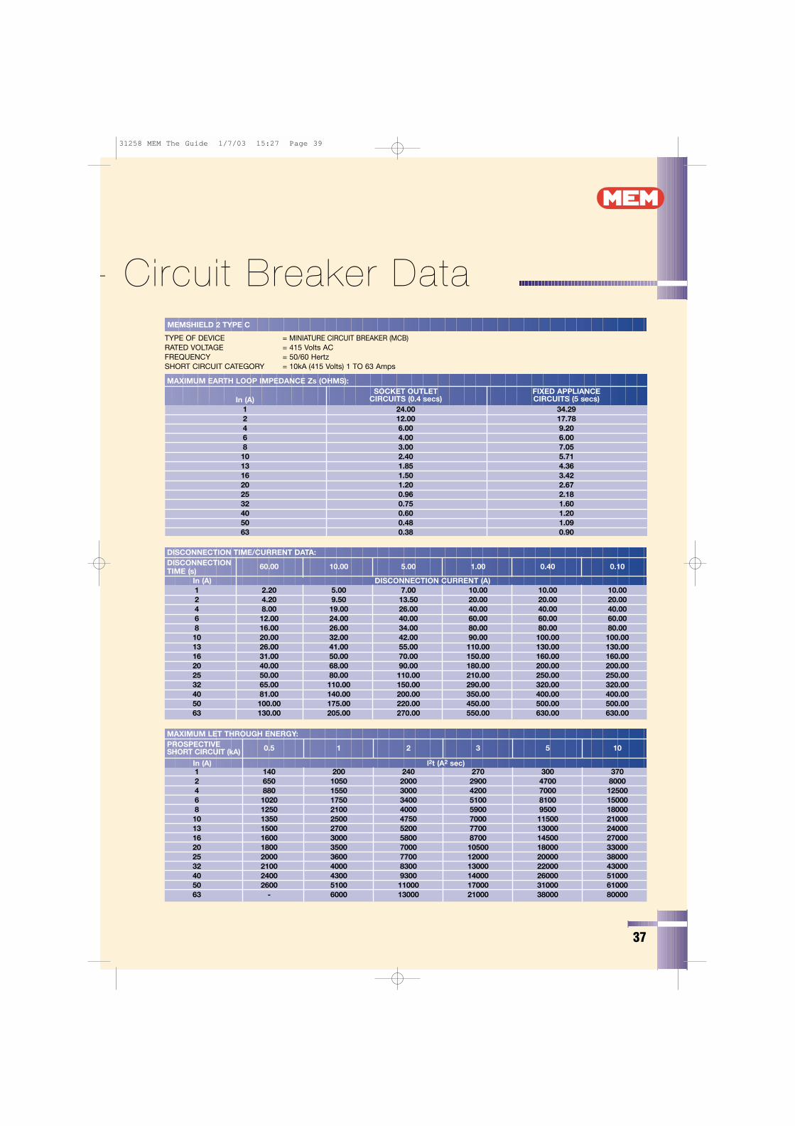
37
- Circuit Breaker DataMEMSHIELD 2 TYPE C
TYPE OF DEVICE = MINIATURE CIRCUIT BREAKER (MCB)RATED VOLTAGE = 415 Volts ACFREQUENCY = 50/60 HertzSHORT CIRCUIT CATEGORY = 10kA (415 Volts) 1 TO 63 Amps
MAXIMUM EARTH LOOP IMPEDANCE Zs (OHMS):SOCKET OUTLET FIXED APPLIANCE
In (A) CIRCUITS (0.4 secs) CIRCUITS (5 secs)1 24.00 34.292 12.00 17.784 6.00 9.206 4.00 6.008 3.00 7.0510 2.40 5.7113 1.85 4.3616 1.50 3.4220 1.20 2.6725 0.96 2.1832 0.75 1.6040 0.60 1.2050 0.48 1.0963 0.38 0.90
DISCONNECTION TIME/CURRENT DATA:DISCONNECTIONTIME (s)
60.00 10.00 5.00 1.00 0.40 0.10
In (A) DISCONNECTION CURRENT (A)1 2.20 5.00 7.00 10.00 10.00 10.002 4.20 9.50 13.50 20.00 20.00 20.004 8.00 19.00 26.00 40.00 40.00 40.006 12.00 24.00 40.00 60.00 60.00 60.008 16.00 26.00 34.00 80.00 80.00 80.0010 20.00 32.00 42.00 90.00 100.00 100.0013 26.00 41.00 55.00 110.00 130.00 130.0016 31.00 50.00 70.00 150.00 160.00 160.0020 40.00 68.00 90.00 180.00 200.00 200.0025 50.00 80.00 110.00 210.00 250.00 250.0032 65.00 110.00 150.00 290.00 320.00 320.0040 81.00 140.00 200.00 350.00 400.00 400.0050 100.00 175.00 220.00 450.00 500.00 500.0063 130.00 205.00 270.00 550.00 630.00 630.00
MAXIMUM LET THROUGH ENERGY:PROSPECTIVESHORT CIRCUIT (kA) 0.5 1 2 3 5 10
In (A) l2t (A2 sec)1 140 200 240 270 300 3702 650 1050 2000 2900 4700 80004 880 1550 3000 4200 7000 125006 1020 1750 3400 5100 8100 150008 1250 2100 4000 5900 9500 1800010 1350 2500 4750 7000 11500 2100013 1500 2700 5200 7700 13000 2400016 1600 3000 5800 8700 14500 2700020 1800 3500 7000 10500 18000 3300025 2000 3600 7700 12000 20000 3800032 2100 4000 8300 13000 22000 4300040 2400 4300 9300 14000 26000 5100050 2600 5100 11000 17000 31000 6100063 - 6000 13000 21000 38000 80000
31258 MEM The Guide 1/7/03 15:27 Page 39
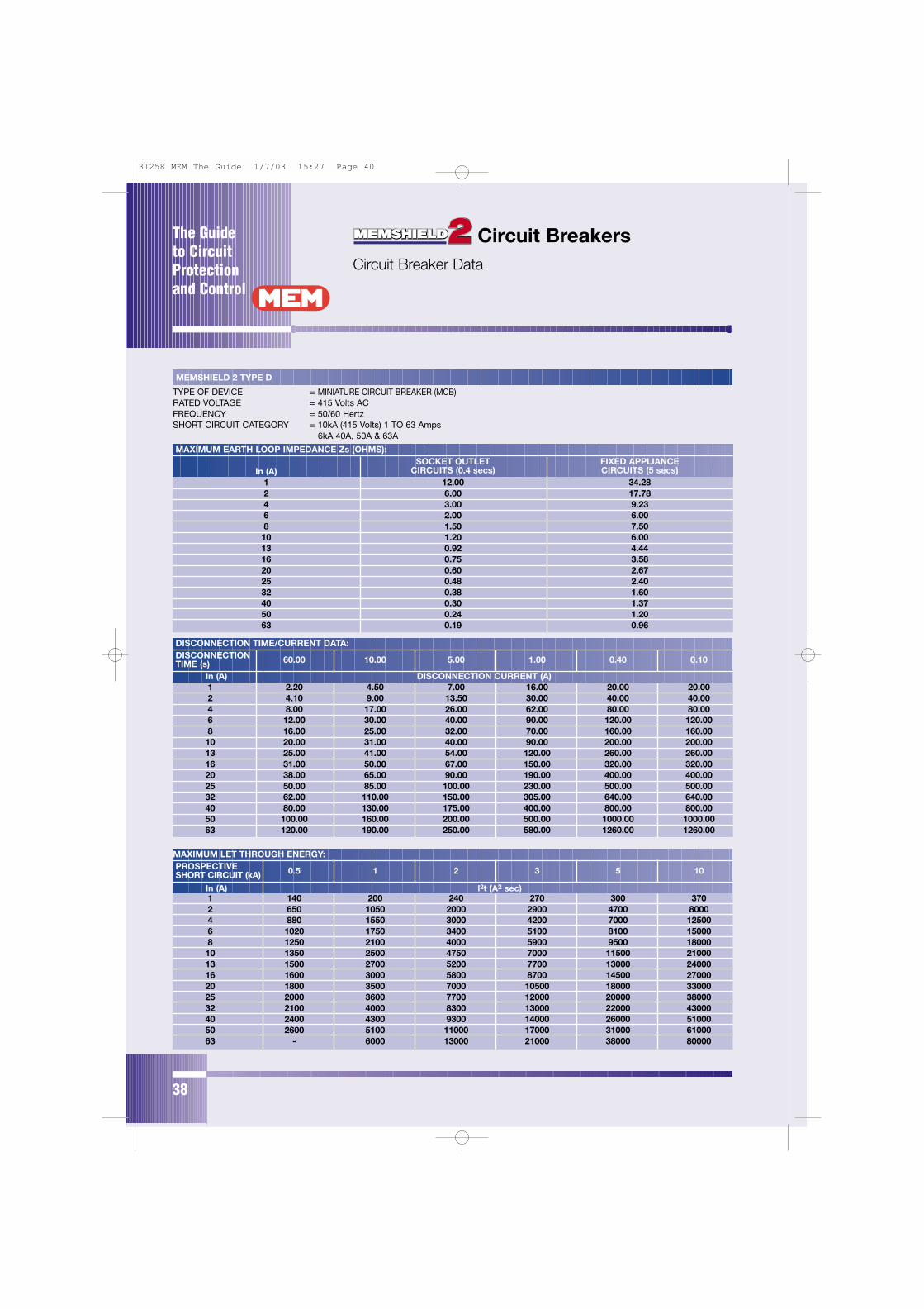
The Guide to CircuitProtectionand Control
38
MEMSHIELD 2 TYPE D
TYPE OF DEVICE = MINIATURE CIRCUIT BREAKER (MCB)RATED VOLTAGE = 415 Volts ACFREQUENCY = 50/60 HertzSHORT CIRCUIT CATEGORY = 10kA (415 Volts) 1 TO 63 Amps
6kA 40A, 50A & 63A
MAXIMUM EARTH LOOP IMPEDANCE Zs (OHMS):SOCKET OUTLET FIXED APPLIANCE
In (A) CIRCUITS (0.4 secs) CIRCUITS (5 secs)1 12.00 34.282 6.00 17.784 3.00 9.236 2.00 6.008 1.50 7.5010 1.20 6.0013 0.92 4.4416 0.75 3.5820 0.60 2.6725 0.48 2.4032 0.38 1.6040 0.30 1.3750 0.24 1.2063 0.19 0.96
DISCONNECTION TIME/CURRENT DATA:DISCONNECTIONTIME (s) 60.00 10.00 5.00 1.00 0.40 0.10
In (A) DISCONNECTION CURRENT (A)1 2.20 4.50 7.00 16.00 20.00 20.002 4.10 9.00 13.50 30.00 40.00 40.004 8.00 17.00 26.00 62.00 80.00 80.006 12.00 30.00 40.00 90.00 120.00 120.008 16.00 25.00 32.00 70.00 160.00 160.0010 20.00 31.00 40.00 90.00 200.00 200.0013 25.00 41.00 54.00 120.00 260.00 260.0016 31.00 50.00 67.00 150.00 320.00 320.0020 38.00 65.00 90.00 190.00 400.00 400.0025 50.00 85.00 100.00 230.00 500.00 500.0032 62.00 110.00 150.00 305.00 640.00 640.0040 80.00 130.00 175.00 400.00 800.00 800.0050 100.00 160.00 200.00 500.00 1000.00 1000.0063 120.00 190.00 250.00 580.00 1260.00 1260.00
MAXIMUM LET THROUGH ENERGY:PROSPECTIVESHORT CIRCUIT (kA) 0.5 1 2 3 5 10
In (A) l2t (A2 sec)1 140 200 240 270 300 3702 650 1050 2000 2900 4700 80004 880 1550 3000 4200 7000 125006 1020 1750 3400 5100 8100 150008 1250 2100 4000 5900 9500 1800010 1350 2500 4750 7000 11500 2100013 1500 2700 5200 7700 13000 2400016 1600 3000 5800 8700 14500 2700020 1800 3500 7000 10500 18000 3300025 2000 3600 7700 12000 20000 3800032 2100 4000 8300 13000 22000 4300040 2400 4300 9300 14000 26000 5100050 2600 5100 11000 17000 31000 6100063 - 6000 13000 21000 38000 80000
Circuit BreakersCircuit Breaker Data
31258 MEM The Guide 1/7/03 15:27 Page 40
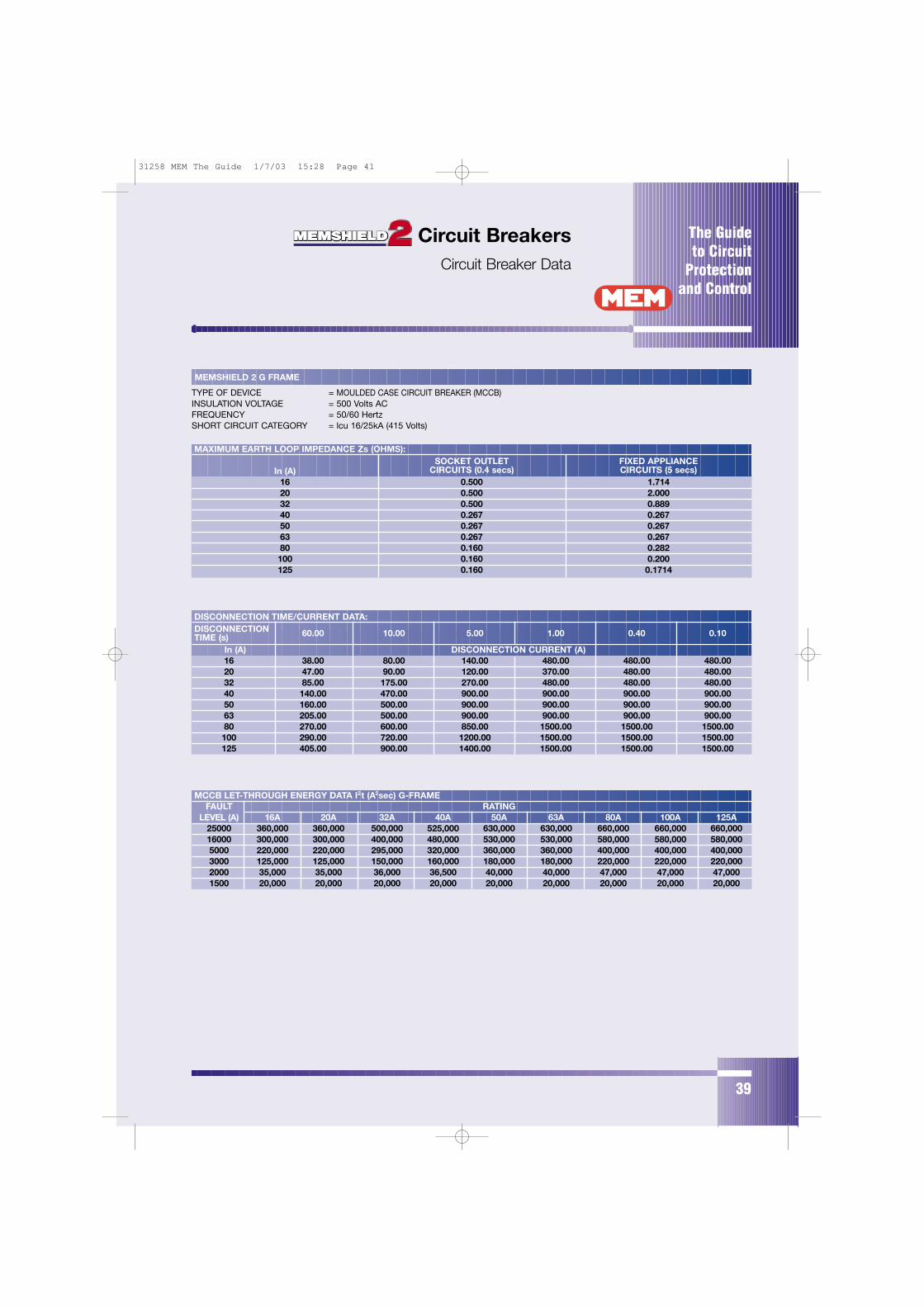
The Guide to Circuit
Protectionand Control
39
Circuit BreakersCircuit Breaker Data
MEMSHIELD 2 G FRAME
TYPE OF DEVICE = MOULDED CASE CIRCUIT BREAKER (MCCB)INSULATION VOLTAGE = 500 Volts ACFREQUENCY = 50/60 HertzSHORT CIRCUIT CATEGORY = lcu 16/25kA (415 Volts)
MAXIMUM EARTH LOOP IMPEDANCE Zs (OHMS):SOCKET OUTLET FIXED APPLIANCE
In (A) CIRCUITS (0.4 secs) CIRCUITS (5 secs)16 0.500 1.71420 0.500 2.00032 0.500 0.88940 0.267 0.26750 0.267 0.26763 0.267 0.26780 0.160 0.282100 0.160 0.200125 0.160 0.1714
DISCONNECTION TIME/CURRENT DATA:DISCONNECTION TIME (s) 60.00 10.00 5.00 1.00 0.40 0.10
In (A) DISCONNECTION CURRENT (A)16 38.00 80.00 140.00 480.00 480.00 480.0020 47.00 90.00 120.00 370.00 480.00 480.0032 85.00 175.00 270.00 480.00 480.00 480.0040 140.00 470.00 900.00 900.00 900.00 900.0050 160.00 500.00 900.00 900.00 900.00 900.0063 205.00 500.00 900.00 900.00 900.00 900.0080 270.00 600.00 850.00 1500.00 1500.00 1500.00100 290.00 720.00 1200.00 1500.00 1500.00 1500.00125 405.00 900.00 1400.00 1500.00 1500.00 1500.00
MCCB LET-THROUGH ENERGY DATA I2t (A2sec) G-FRAMEFAULT RATING
LEVEL (A) 16A 20A 32A 40A 50A 63A 80A 100A 125A25000 360,000 360,000 500,000 525,000 630,000 630,000 660,000 660,000 660,00016000 300,000 300,000 400,000 480,000 530,000 530,000 580,000 580,000 580,0005000 220,000 220,000 295,000 320,000 360,000 360,000 400,000 400,000 400,0003000 125,000 125,000 150,000 160,000 180,000 180,000 220,000 220,000 220,0002000 35,000 35,000 36,000 36,500 40,000 40,000 47,000 47,000 47,0001500 20,000 20,000 20,000 20,000 20,000 20,000 20,000 20,000 20,000
31258 MEM The Guide 1/7/03 15:28 Page 41
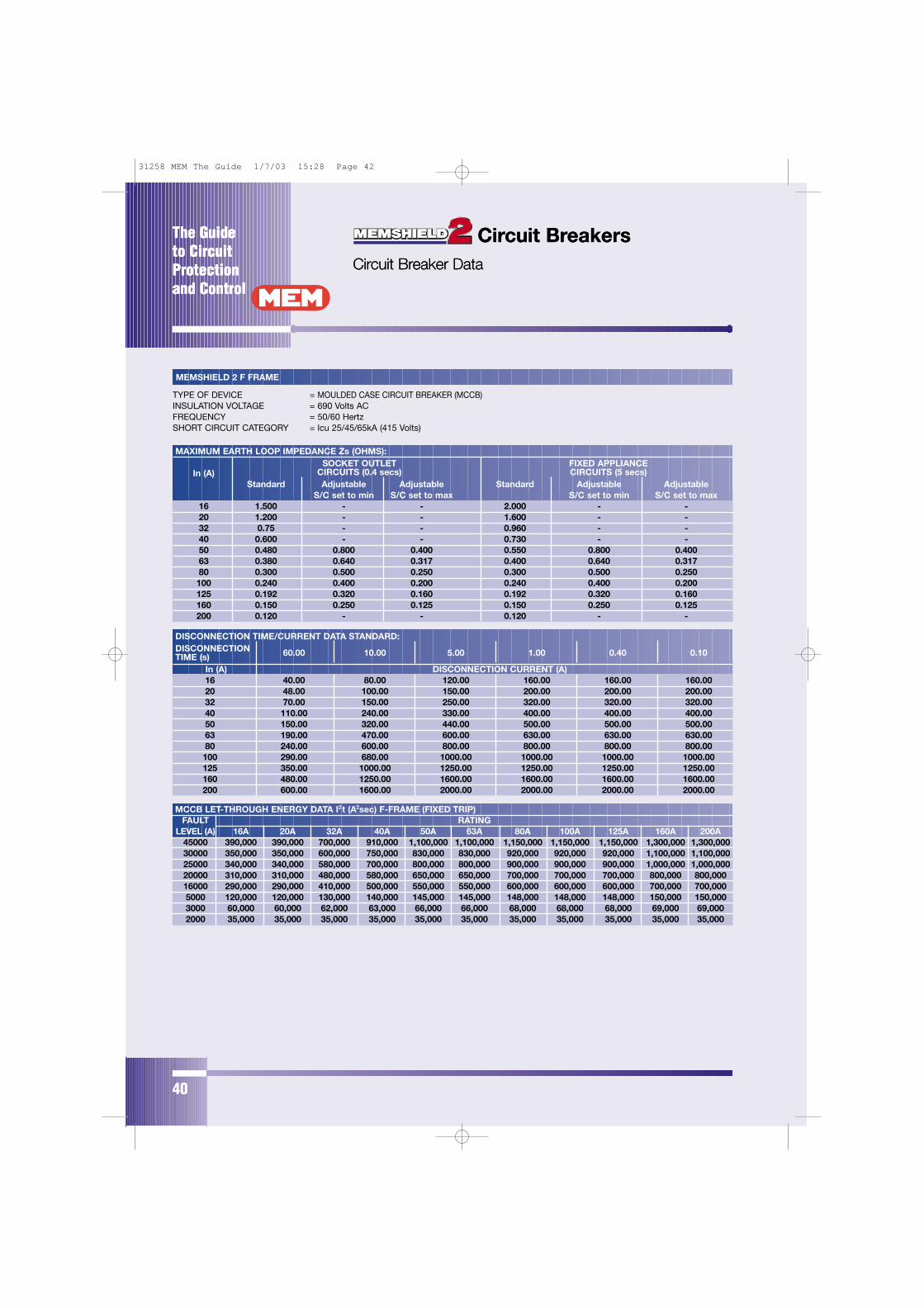
The Guide to CircuitProtectionand Control
Circuit BreakersCircuit Breaker Data
The Guide to CircuitProtectionand Control
40
Circuit BreakersCircuit Breaker Data
MEMSHIELD 2 F FRAME
TYPE OF DEVICE = MOULDED CASE CIRCUIT BREAKER (MCCB)INSULATION VOLTAGE = 690 Volts ACFREQUENCY = 50/60 HertzSHORT CIRCUIT CATEGORY = lcu 25/45/65kA (415 Volts)
MAXIMUM EARTH LOOP IMPEDANCE Zs (OHMS):SOCKET OUTLET FIXED APPLIANCE
In (A) CIRCUITS (0.4 secs) CIRCUITS (5 secs)Standard Adjustable Adjustable Standard Adjustable Adjustable
S/C set to min S/C set to max S/C set to min S/C set to max16 1.500 - - 2.000 - -20 1.200 - - 1.600 - -32 0.75 - - 0.960 - -40 0.600 - - 0.730 - -50 0.480 0.800 0.400 0.550 0.800 0.40063 0.380 0.640 0.317 0.400 0.640 0.31780 0.300 0.500 0.250 0.300 0.500 0.250100 0.240 0.400 0.200 0.240 0.400 0.200125 0.192 0.320 0.160 0.192 0.320 0.160160 0.150 0.250 0.125 0.150 0.250 0.125200 0.120 - - 0.120 - -
DISCONNECTION TIME/CURRENT DATA STANDARD:DISCONNECTION TIME (s) 60.00 10.00 5.00 1.00 0.40 0.10
In (A) DISCONNECTION CURRENT (A)16 40.00 80.00 120.00 160.00 160.00 160.0020 48.00 100.00 150.00 200.00 200.00 200.0032 70.00 150.00 250.00 320.00 320.00 320.0040 110.00 240.00 330.00 400.00 400.00 400.0050 150.00 320.00 440.00 500.00 500.00 500.0063 190.00 470.00 600.00 630.00 630.00 630.0080 240.00 600.00 800.00 800.00 800.00 800.00100 290.00 680.00 1000.00 1000.00 1000.00 1000.00125 350.00 1000.00 1250.00 1250.00 1250.00 1250.00160 480.00 1250.00 1600.00 1600.00 1600.00 1600.00200 600.00 1600.00 2000.00 2000.00 2000.00 2000.00
MCCB LET-THROUGH ENERGY DATA I2t (A2sec) F-FRAME (FIXED TRIP)FAULT RATING
LEVEL (A) 16A 20A 32A 40A 50A 63A 80A 100A 125A 160A 200A45000 390,000 390,000 700,000 910,000 1,100,000 1,100,000 1,150,000 1,150,000 1,150,000 1,300,000 1,300,00030000 350,000 350,000 600,000 750,000 830,000 830,000 920,000 920,000 920,000 1,100,000 1,100,00025000 340,000 340,000 580,000 700,000 800,000 800,000 900,000 900,000 900,000 1,000,000 1,000,00020000 310,000 310,000 480,000 580,000 650,000 650,000 700,000 700,000 700,000 800,000 800,00016000 290,000 290,000 410,000 500,000 550,000 550,000 600,000 600,000 600,000 700,000 700,0005000 120,000 120,000 130,000 140,000 145,000 145,000 148,000 148,000 148,000 150,000 150,0003000 60,000 60,000 62,000 63,000 66,000 66,000 68,000 68,000 68,000 69,000 69,0002000 35,000 35,000 35,000 35,000 35,000 35,000 35,000 35,000 35,000 35,000 35,000
31258 MEM The Guide 1/7/03 15:28 Page 42
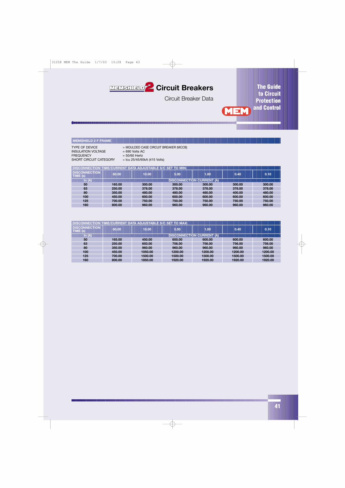
The Guide to Circuit
Protectionand Control
41
Circuit BreakersCircuit Breaker Data
MEMSHIELD 2 F FRAME
TYPE OF DEVICE = MOULDED CASE CIRCUIT BREAKER (MCCB)INSULATION VOLTAGE = 690 Volts ACFREQUENCY = 50/60 HertzSHORT CIRCUIT CATEGORY = lcu 25/45/65kA (415 Volts)
DISCONNECTION TIME/CURRENT DATA ADJUSTABLE S/C SET TO MIN:DISCONNECTION TIME (s) 60.00 10.00 5.00 1.00 0.40 0.10
In (A) DISCONNECTION CURRENT (A)50 165.00 300.00 300.00 300.00 300.00 300.0063 250.00 378.00 378.00 378.00 378.00 378.0080 350.00 480.00 480.00 480.00 400.00 480.00100 450.00 600.00 600.00 600.00 600.00 600.00125 700.00 750.00 750.00 750.00 750.00 750.00160 800.00 960.00 960.00 960.00 960.00 960.00
DISCONNECTION TIME/CURRENT DATA ADJUSTABLE S/C SET TO MAX:DISCONNECTION TIME (s) 60.00 10.00 5.00 1.00 0.40 0.10
In (A) DISCONNECTION CURRENT (A)50 165.00 450.00 600.00 600.00 600.00 600.0063 250.00 650.00 756.00 756.00 756.00 756.0080 350.00 960.00 960.00 960.00 960.00 960.00100 450.00 1050.00 1200.00 1200.00 1200.00 1200.00125 700.00 1500.00 1500.00 1500.00 1500.00 1500.00160 800.00 1850.00 1920.00 1920.00 1920.00 1920.00
31258 MEM The Guide 1/7/03 15:28 Page 43

The Guide to CircuitProtectionand Control
42
Circuit BreakersCircuit Breaker Data
MEMSHIELD 2 J FRAME
TYPE OF DEVICE = MOULDED CASE CIRCUIT BREAKER (MCCB)INSULATION VOLTAGE = 690 Volts ACFREQUENCY = 50/60 HertzSHORT CIRCUIT CATEGORY = lcu 36/65kA (415 Volts)
MAXIMUM EARTH LOOP IMPEDANCE Zs (OHMS):SOCKET OUTLET FIXED APPLIANCE
In (A) CIRCUITS (0.4 secs) CIRCUITS (5 secs)Adjustable Adjustable Adjustable Adjustable
S/C Set to Min S/C Set to Max S/C Set to Min S/C Set to Max
200 0.200 0.100 0.200 0.100250 0.160 0.080 0.160 0.080
MCCB LET-THROUGH ENERGY DATA I2t (A2sec) J-FRAMEFAULT RATING
LEVEL (A) 160A 200A 250A65000 1,500,000 2,300,000 3,400,00050000 1,300,000 2,200,000 3,100,00036000 1,150,000 1,700,000 2,700,00025000 1,000,000 1,400,000 2,400,00016000 700,000 1,100,000 1,800,00010000 420,000 620,000 1,150,0005000 190,000 230,000 390,0003000 90,000 95,000 125,0002500 62,000 65,000 85,000
DISCONNECTION TIME/CURRENT DATA ADJUSTABLE S/C SET TO MAX:DISCONNECTION TIME (s) 60.00 10.00 5.00 1.00 0.40 0.10
In (A) DISCONNECTION CURRENT (A)200 600.00 2400.00 2400.00 2400.00 2400.00 2400.00250 1000.00 3000.00 3000.00 3000.00 3000.00 3000.00
DISCONNECTION TIME/CURRENT DATA ADJUSTABLE S/C SET TO MIN:DISCONNECTION TIME (s) 60.00 10.00 5.00 1.00 0.40 0.10
In (A) DISCONNECTION CURRENT (A)200 600.00 1200.00 1200.00 1200.00 1200.00 1200.00250 1000.00 1500.00 1500.00 1500.00 1500.00 1200.00
31258 MEM The Guide 1/7/03 15:28 Page 44
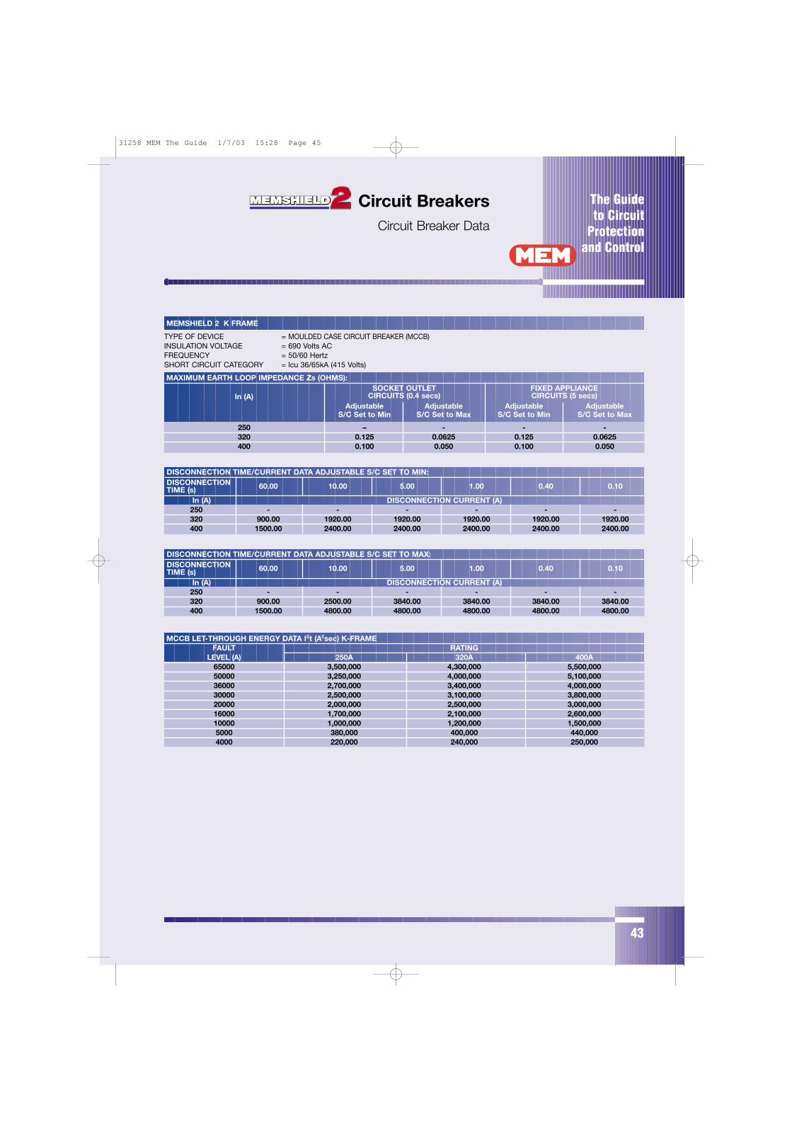
The Guide to Circuit
Protectionand Control
43
Circuit BreakersCircuit Breaker Data
MEMSHIELD 2 K FRAME
TYPE OF DEVICE = MOULDED CASE CIRCUIT BREAKER (MCCB)INSULATION VOLTAGE = 690 Volts ACFREQUENCY = 50/60 HertzSHORT CIRCUIT CATEGORY = lcu 36/65kA (415 Volts)
MAXIMUM EARTH LOOP IMPEDANCE Zs (OHMS):SOCKET OUTLET FIXED APPLIANCE
In (A) CIRCUITS (0.4 secs) CIRCUITS (5 secs)Adjustable Adjustable Adjustable Adjustable
S/C Set to Min S/C Set to Max S/C Set to Min S/C Set to Max
250 – - - -320 0.125 0.0625 0.125 0.0625400 0.100 0.050 0.100 0.050
DISCONNECTION TIME/CURRENT DATA ADJUSTABLE S/C SET TO MAX:DISCONNECTION TIME (s) 60.00 10.00 5.00 1.00 0.40 0.10
In (A) DISCONNECTION CURRENT (A)250 - - - - - -320 900.00 2500.00 3840.00 3840.00 3840.00 3840.00400 1500.00 4800.00 4800.00 4800.00 4800.00 4800.00
DISCONNECTION TIME/CURRENT DATA ADJUSTABLE S/C SET TO MIN:DISCONNECTION TIME (s) 60.00 10.00 5.00 1.00 0.40 0.10
In (A) DISCONNECTION CURRENT (A)250 - - - - - -320 900.00 1920.00 1920.00 1920.00 1920.00 1920.00400 1500.00 2400.00 2400.00 2400.00 2400.00 2400.00
MCCB LET-THROUGH ENERGY DATA I2t (A2sec) K-FRAMEFAULT RATING
LEVEL (A) 250A 320A 400A65000 3,500,000 4,300,000 5,500,00050000 3,250,000 4,000,000 5,100,00036000 2,700,000 3,400,000 4,000,00030000 2,500,000 3,100,000 3,800,00020000 2,000,000 2,500,000 3,000,00016000 1,700,000 2,100,000 2,600,00010000 1,000,000 1,200,000 1,500,0005000 380,000 400,000 440,0004000 220,000 240,000 250,000
31258 MEM The Guide 1/7/03 15:28 Page 45
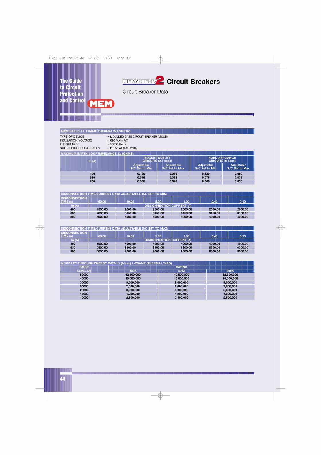
The Guide to CircuitProtectionand Control
44
Circuit BreakersCircuit Breaker Data
MEMSHIELD 2 L FRAME THERMAL/MAGNETIC
TYPE OF DEVICE = MOULDED CASE CIRCUIT BREAKER (MCCB)INSULATION VOLTAGE = 690 Volts ACFREQUENCY = 50/60 HertzSHORT CIRCUIT CATEGORY = lcu 50kA (415 Volts)
MAXIMUM EARTH LOOP IMPEDANCE Zs (OHMS):SOCKET OUTLET FIXED APPLIANCE
In (A) CIRCUITS (0.4 secs) CIRCUITS (5 secs)Adjustable Adjustable Adjustable Adjustable
S/C Set to Min S/C Set to Max S/C Set to Min S/C Set to Max
400 0.120 0.060 0.120 0.060630 0.076 0.038 0.076 0.038800 0.060 0.030 0.060 0.030
DISCONNECTION TIME/CURRENT DATA ADJUSTABLE S/C SET TO MIN:DISCONNECTION TIME (s) 60.00 10.00 5.00 1.00 0.40 0.10
In (A) DISCONNECTION CURRENT (A)400 1500.00 2000.00 2000.00 2000.00 2000.00 2000.00630 2800.00 3150.00 3150.00 3150.00 3150.00 3150.00800 4000.00 4000.00 4000.00 4000.00 4000.00 4000.00
DISCONNECTION TIME/CURRENT DATA ADJUSTABLE S/C SET TO MAX:DISCONNECTION TIME (s) 60.00 10.00 5.00 1.00 0.40 0.10
In (A) DISCONNECTION CURRENT (A)400 1500.00 4000.00 4000.00 4000.00 4000.00 4000.00630 2800.00 6300.00 6300.00 6300.00 6300.00 6300.00800 4000.00 8000.00 8000.00 8000.00 8000.00 8000.00
MCCB LET-THROUGH ENERGY DATA I2t (A2sec) L-FRAME (THERMAL/MAG)FAULT RATING
LEVEL (A) 400A 630A 800A50000 12,500,000 12,500,000 12,500,00040000 10,000,000 10,000,000 10,000,00035000 9,000,000 9,000,000 9,000,00030000 7,800,000 7,800,000 7,800,00020000 6,000,000 6,000,000 6,000,00015000 4,200,000 4,200,000 4,200,00010000 2,500,000 2,500,000 2,500,000
31258 MEM The Guide 1/7/03 15:28 Page 46
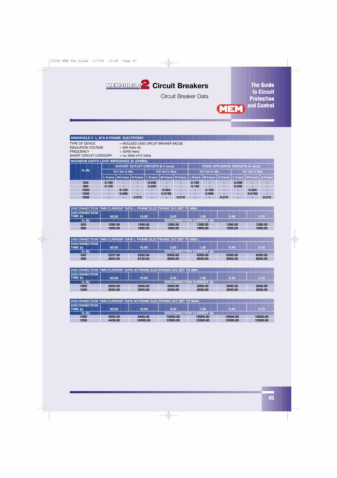
The Guide to Circuit
Protectionand Control
45
MEMSHIELD 2 L, M & N FRAME ELECTRONIC
TYPE OF DEVICE = MOULDED CASE CIRCUIT BREAKER (MCCB)INSULATION VOLTAGE = 690 Volts ACFREQUENCY = 50/60 HertzSHORT CIRCUIT CATEGORY = lcu 50kA (415 Volts)
MAXIMUM EARTH LOOP IMPEDANCE Zs (OHMS):
SOCKET OUTLET CIRCUITS (0.4 secs) FIXED APPLIANCE CIRCUITS (5 secs)In (A) S/C Set to Min S/C Set to Max S/C Set to Min S/C Set to Max
L Frame M Frame N Frame L Frame M Frame N Frame L Frame M Frame N Frame L Frame M Frame N Frame
630 0.190 - - 0.038 - - 0.190 - - 0.038 - -800 0.150 - - 0.030 - - 0.150 - - 0.030 - -1000 - 0.120 - - 0.024 - - 0.120 - - 0.024 -1250 - 0.096 - - 0.0192 - - 0.096 - - 0.0192 -1600 - - 0.075 - - 0.015 - - 0.075 - - 0.015
DISCONNECTION TIME/CURRENT DATA L FRAME ELECTRONIC S/C SET TO MAX:DISCONNECTION TIME (s) 60.00 10.00 5.00 1.00 0.40 0.10
In (A) DISCONNECTION CURRENT (A)630 2237.00 5292.00 6300.00 6300.00 6300.00 6300.00800 2840.00 6720.00 8000.00 8000.00 8000.00 8000.00
DISCONNECTION TIME/CURRENT DATA L FRAME ELECTRONIC S/C SET TO MIN:DISCONNECTION TIME (s) 60.00 10.00 5.00 1.00 0.40 0.10
In (A) DISCONNECTION CURRENT (A)630 1260.00 1260.00 1260.00 1260.00 1260.00 1260.00800 1600.00 1600.00 1600.00 1600.00 1600.00 1600.00
DISCONNECTION TIME/CURRENT DATA M FRAME ELECTRONIC S/C SET TO MIN:DISCONNECTION TIME (s) 60.00 10.00 5.00 1.00 0.40 0.10
In (A) DISCONNECTION CURRENT (A)1000 2000.00 2000.00 2000.00 2000.00 2000.00 2000.001250 2500.00 2500.00 2500.00 2500.00 2500.00 2500.00
Circuit BreakersCircuit Breaker Data
DISCONNECTION TIME/CURRENT DATA M FRAME ELECTRONIC S/C SET TO MAX:DISCONNECTION TIME (s) 60.00 10.00 5.00 1.00 0.40 0.10
In (A) DISCONNECTION CURRENT (A)1000 3500.00 8400.00 10000.00 10000.00 10000.00 10000.001250 4438.00 10500.00 12500.00 12500.00 12500.00 12500.00
31258 MEM The Guide 1/7/03 15:28 Page 47
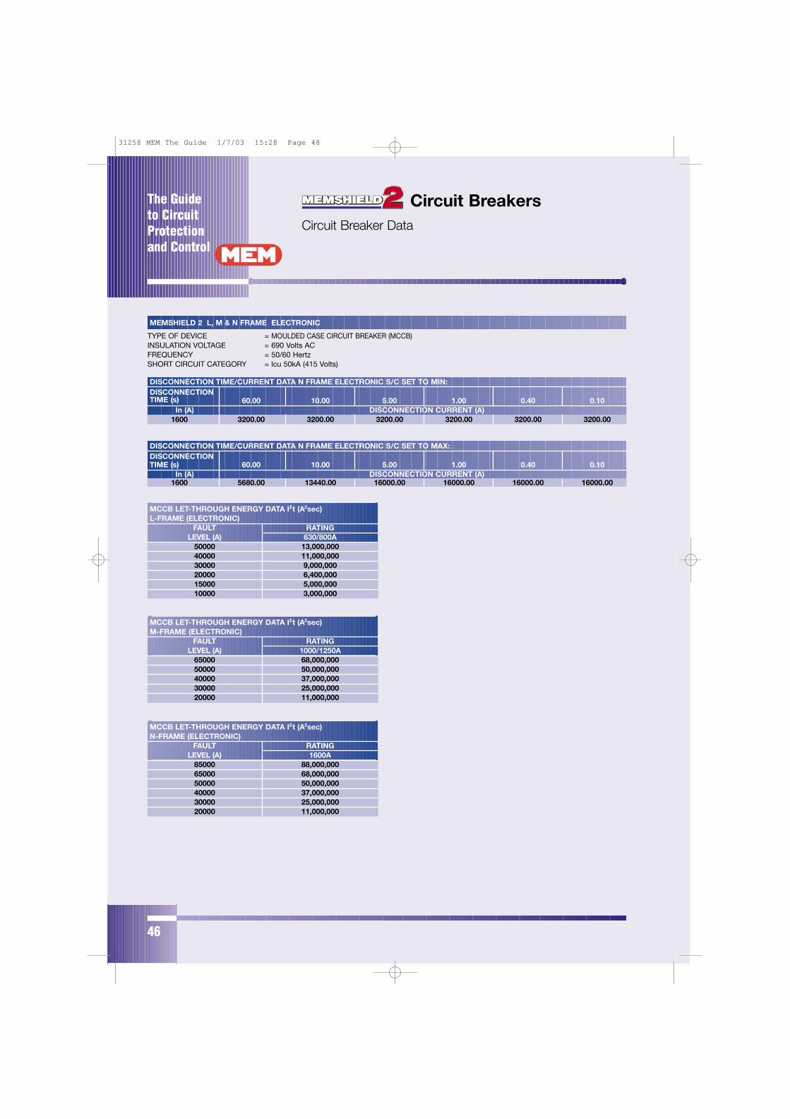
The Guide to CircuitProtectionand Control
46
Circuit BreakersCircuit Breaker Data
DISCONNECTION TIME/CURRENT DATA N FRAME ELECTRONIC S/C SET TO MAX:DISCONNECTION TIME (s) 60.00 10.00 5.00 1.00 0.40 0.10
In (A) DISCONNECTION CURRENT (A)1600 5680.00 13440.00 16000.00 16000.00 16000.00 16000.00
DISCONNECTION TIME/CURRENT DATA N FRAME ELECTRONIC S/C SET TO MIN:DISCONNECTION TIME (s) 60.00 10.00 5.00 1.00 0.40 0.10
In (A) DISCONNECTION CURRENT (A)1600 3200.00 3200.00 3200.00 3200.00 3200.00 3200.00
MEMSHIELD 2 L, M & N FRAME ELECTRONIC
TYPE OF DEVICE = MOULDED CASE CIRCUIT BREAKER (MCCB)INSULATION VOLTAGE = 690 Volts ACFREQUENCY = 50/60 HertzSHORT CIRCUIT CATEGORY = lcu 50kA (415 Volts)
MCCB LET-THROUGH ENERGY DATA I2t (A2sec) L-FRAME (ELECTRONIC)
FAULT RATINGLEVEL (A) 630/800A
50000 13,000,00040000 11,000,00030000 9,000,00020000 6,400,00015000 5,000,00010000 3,000,000
MCCB LET-THROUGH ENERGY DATA I2t (A2sec) N-FRAME (ELECTRONIC)
FAULT RATINGLEVEL (A) 1600A
85000 88,000,00065000 68,000,00050000 50,000,00040000 37,000,00030000 25,000,00020000 11,000,000
MCCB LET-THROUGH ENERGY DATA I2t (A2sec) M-FRAME (ELECTRONIC)
FAULT RATINGLEVEL (A) 1000/1250A
65000 68,000,00050000 50,000,00040000 37,000,00030000 25,000,00020000 11,000,000
31258 MEM The Guide 1/7/03 15:28 Page 48
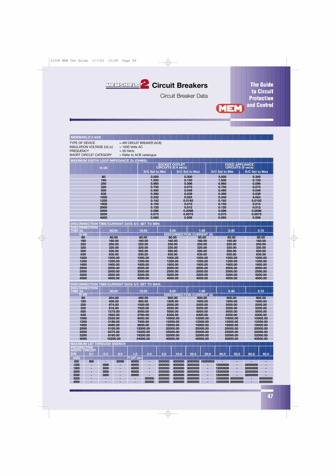
The Guide to Circuit
Protectionand Control
47
Circuit BreakersCircuit Breaker Data
MEMSHIELD 2 ACB
TYPE OF DEVICE = AIR CIRCUIT BREAKER (ACB)INSULATION VOLTAGE (Ui) (v) = 1000 Volts ACFREQUENCY = 50 Hertz SHORT CIRCUIT CATEGORY = Refer to ACB catalogue
MAXIMUM EARTH LOOP IMPEDANCE Zs (OHMS):SOCKET OUTLET FIXED APPLIANCE
In (A) CIRCUITS (0.4 secs) CIRCUITS (5 secs)S/C Set to Min S/C Set to Max S/C Set to Min S/C Set to Max
80 3.000 0.300 3.000 0.300160 1.500 0.150 1.500 0.150250 0.960 0.096 0.960 0.096320 0.750 0.075 0.750 0.075500 0.480 0.048 0.480 0.048630 0.380 0.038 0.380 0.0381000 0.240 0.024 0.240 0.0241250 0.192 0.0192 0.192 0.01921600 0.150 0.015 0.150 0.0152000 0.120 0.012 0.120 0.0122500 0.096 0.0096 0.096 0.00963200 0.075 0.0075 0.075 0.00754000 0.060 0.006 0.060 0.006
DISCONNECTION TIME/CURRENT DATA S/C SET TO MIN:DISCONNECTION TIME (s) 60.00 10.00 5.00 1.00 0.40 0.10
In (A) DISCONNECTION CURRENT (A)80 80.00 80.00 80.00 80.00 80.00 80.00160 160.00 160.00 160.00 160.00 160.00 160.00250 250.00 250.00 250.00 250.00 250.00 250.00320 320.00 320.00 320.00 320.00 320.00 320.00500 500.00 500.00 500.00 500.00 500.00 500.00630 630.00 630.00 630.00 630.00 630.00 630.001000 1000.00 1000.00 1000.00 1000.00 1000.00 1000.001250 1250.00 1250.00 1250.00 1250.00 1250.00 1250.001600 1600.00 1600.00 1600.00 1600.00 1600.00 1600.002000 2000.00 2000.00 2000.00 2000.00 2000.00 2000.002500 2500.00 2500.00 2500.00 2500.00 2500.00 2500.003200 3200.00 3200.00 3200.00 3200.00 3200.00 3200.004000 4000.00 4000.00 4000.00 4000.00 4000.00 4000.00
DISCONNECTION TIME/CURRENT DATA S/C SET TO MAX:DISCONNECTION TIME (s) 60.00 10.00 5.00 1.00 0.40 0.10
In (A) DISCONNECTION CURRENT (A)80 204.00 480.00 800.00 800.00 800.00 800.00160 408.00 960.00 1600.00 1600.00 1600.00 1600.00250 674.00 1500.00 2500.00 2500.00 2500.00 2500.00320 816.00 1920.00 3200.00 3200.00 3200.00 3200.00500 1275.00 3000.00 5000.00 5000.00 5000.00 5000.00630 1605.00 3780.00 6300.00 6300.00 6300.00 6300.001000 2550.00 6000.00 10000.00 10000.00 10000.00 10000.001250 3188.00 7500.00 12500.00 12500.00 12500.00 12500.001600 4080.00 9600.00 16000.00 16000.00 16000.00 16000.002000 5100.00 12000.00 20000.00 20000.00 20000.00 20000.002500 6375.00 15000.00 25000.00 25000.00 25000.00 25000.003200 8160.00 19200.00 32000.00 32000.00 32000.00 32000.004000 10200.00 24000.00 40000.00 40000.00 40000.00 40000.00
MAXIMUM LET THROUGH ENERGY:PROSPECTIVESHORT CIRCUIT (kA) 0.1 0.2 0.5 1.0 2.0 5.0 10.0 20.0 35.0 40.0 50.0 65.0 85.0
In(A) l2t (A2 sec)630 800 - 20000 80000 - 2000000 8000000 30000000 100000000 - - - -1250 - 3000 - 80000 - 2000000 8000000 30000000 - 120000000 - 320000000 -1600 - 3000 - 80000 - 2000000 8000000 30000000 - 120000000 - 320000000 -2000 - 3000 - 80000 - 2000000 8000000 30000000 - 120000000 - 320000000 -2500 - 3000 - 80000 - 2000000 8000000 30000000 - 120000000 - 320000000 -3200 - - - - 300000 2000000 8000000 30000000 - 120000000 200000000 - 6000000004000 - - - - 300000 2000000 8000000 30000000 - 120000000 200000000 - 600000000
31258 MEM The Guide 1/7/03 15:28 Page 49

48
Paramount HRC Cartridge
Eaton MEM HRC fuselinks are manufactured to exacting standards
using precision assembly methods and undergo rigorous quality
checking before dispatch including resistance testing all production.
This ensures that performance will be consistent and conform with
published characteristics within close tolerances. Type tests on
Eaton MEM equipment have been performed using Eaton MEM
fuselinks and the exclusive use of Eaton MEM fuselinks in Eaton
MEM equipment will extend the warranty period to 3 years.
Eaton MEM industrial and general purpose fuselinks have a
breaking range and utilization category gG which replaces the old
class Q1 fusing factor. "g" indicates a full range breaking capacity
fuselink and "G" indicates a fuselink for general application.
Eaton MEM motor circuit protection fuselinks have a breaking
range and utilization category gM indicating a full range breaking
capacity fuselink for the protection of motor circuits. These fuselinks
have a dual current rating separated by the letter "M".
The lower current rating is the maximum continuous rating which
also determines the rating and size of equipment to which the fuse
is fitted. The higher current rating is the time current characteristic
of the fuselink which determines its ability to withstand the motor
starting current. Their selection frequently permits the use of lower
rated switch and/or fusegear than would be the case using gG
fuselinks with a consequent cost saving. Type gG fuselinks however
may still be used and are the preferred option for assisted start
motors where starting currents are reduced.
Technical information for these products is available from Eaton
MEM’s Customer Services Department.
Eaton MEM fuselinks are designed and manufactured in accordance
with a Quality Management System in accordance with ISO 9001
assessed by BSI. Most fuselinks are ASTA Certified for a breaking
capacity of 80kA at 415V or 550V a.c. and are endorsed ASTA 20
CERT showing compliance with the rules of the ASTA 20 scheme
which includes assessment of the Quality Management System to
ISO 9002 and detailed auditing of fuselink manufacture.
Eaton MEM have for many years participated in developing and
influencing fuse standards through EIEMA and BSI at national level
and IEC at international level and therefore are able to produce
designs incorporating forthcoming changes to standards.
31258 MEM The Guide 1/7/03 15:28 Page 50
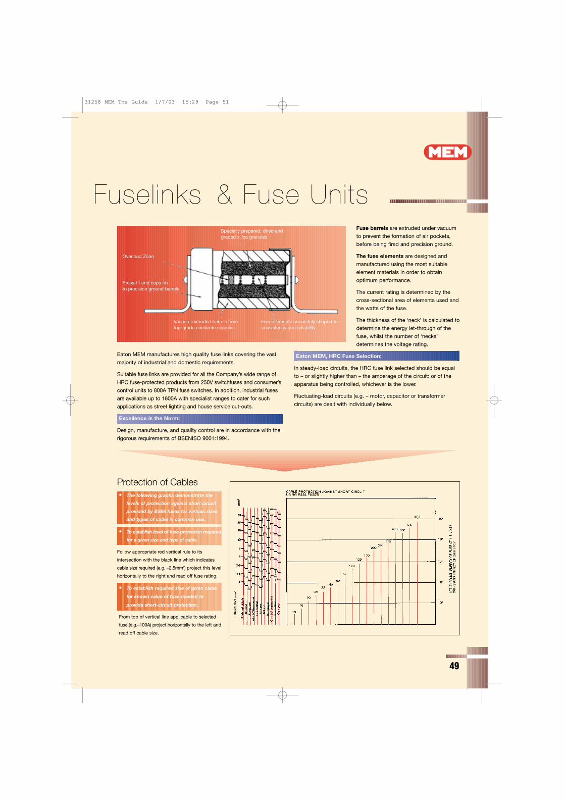
Fuse barrels are extruded under vacuum
to prevent the formation of air pockets,
before being fired and precision ground.
The fuse elements are designed and
manufactured using the most suitable
element materials in order to obtain
optimum performance.
The current rating is determined by the
cross-sectional area of elements used and
the watts of the fuse.
The thickness of the ‘neck’ is calculated to
determine the energy let-through of the
fuse, whilst the number of ‘necks’
determines the voltage rating.
Eaton MEM, HRC Fuse Selection:
In steady-load circuits, the HRC fuse link selected should be equal
to – or slightly higher than – the amperage of the circuit: or of the
apparatus being controlled, whichever is the lower.
Fluctuating-load circuits (e.g. – motor, capacitor or transformer
circuits) are dealt with individually below.
49
e Fuselinks & Fuse Units
Eaton MEM manufactures high quality fuse links covering the vast
majority of industrial and domestic requirements.
Suitable fuse links are provided for all the Company’s wide range of
HRC fuse-protected products from 250V switchfuses and consumer’s
control units to 800A TPN fuse switches. In addition, industrial fuses
are available up to 1600A with specialist ranges to cater for such
applications as street lighting and house service cut-outs.
Excellence is the Norm:
Design, manufacture, and quality control are in accordance with the
rigorous requirements of BSENISO 9001:1994.
Protection of Cables
• To establish level of fuse protection required
for a given size and type of cable.
Follow appropriate red vertical rule to its
intersection with the black line which indicates
cable size required (e.g, –2.5mm2) project this level
horizontally to the right and read off fuse rating.
• To establish required size of given cable
for known value of fuse needed to
provide short-circuit protection.
From top of vertical line applicable to selected
fuse (e.g.–100A) project horizontally to the left and
read off cable size.
• The following graphs demonstrate the
levels of protection against short circuit
provided by BS88 fuses for various sizes
and types of cable in common use.
Specially prepared, dried and graded silica granules
Overload Zone
Press-fit end caps on to precision ground barrels
Vacuum-extruded barrels fromtop-grade cordierite ceramic
Fuse elements accurately shaped forconsistency and reliability
31258 MEM The Guide 1/7/03 15:29 Page 51
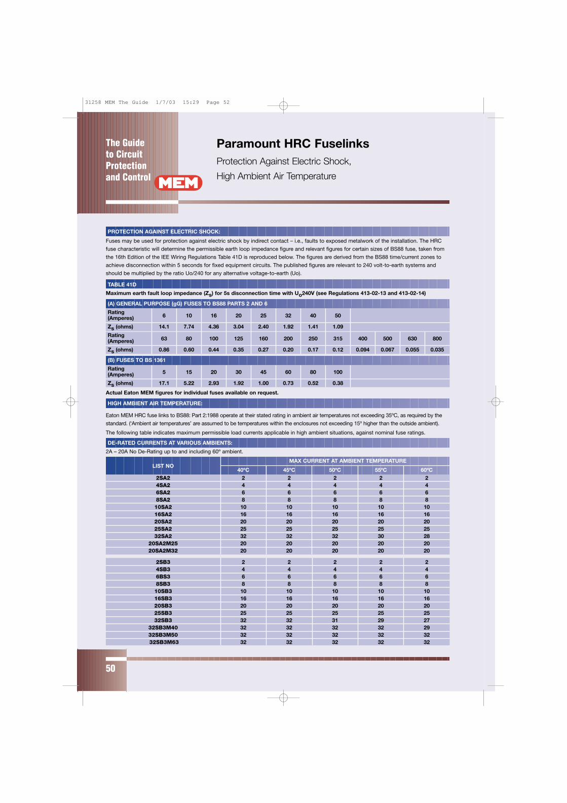
The Guide to CircuitProtectionand Control
50
Paramount HRC FuselinksProtection Against Electric Shock,
High Ambient Air Temperature
MAX CURRENT AT AMBIENT TEMPERATURELIST NO
40ºC 45ºC 50ºC 55ºC 60ºC2SA2 2 2 2 2 24SA2 4 4 4 4 46SA2 6 6 6 6 68SA2 8 8 8 8 810SA2 10 10 10 10 1016SA2 16 16 16 16 1620SA2 20 20 20 20 2025SA2 25 25 25 25 2532SA2 32 32 32 30 28
20SA2M25 20 20 20 20 2020SA2M32 20 20 20 20 20
2SB3 2 2 2 2 24SB3 4 4 4 4 46BS3 6 6 6 6 68SB3 8 8 8 8 810SB3 10 10 10 10 1016SB3 16 16 16 16 1620SB3 20 20 20 20 2025SB3 25 25 25 25 2532SB3 32 32 31 29 27
32SB3M40 32 32 32 32 2932SB3M50 32 32 32 32 3232SB3M63 32 32 32 32 32
PROTECTION AGAINST ELECTRIC SHOCK:
Fuses may be used for protection against electric shock by indirect contact – i.e., faults to exposed metalwork of the installation. The HRC
fuse characteristic will determine the permissible earth loop impedance figure and relevant figures for certain sizes of BS88 fuse, taken from
the 16th Edition of the IEE Wiring Regulations Table 41D is reproduced below. The figures are derived from the BS88 time/current zones to
achieve disconnection within 5 seconds for fixed equipment circuits. The published figures are relevant to 240 volt-to-earth systems and
should be multiplied by the ratio Uo/240 for any alternative voltage-to-earth (Uo).
TABLE 41D
Maximum earth fault loop impedance (Zs) for 5s disconnection time with Uo240V (see Regulations 413-02-13 and 413-02-14)
(A) GENERAL PURPOSE (gG) FUSES TO BS88 PARTS 2 AND 6
Rating6 10 16 20 25 32 40 50(Amperes)
Zs (ohms) 14.1 7.74 4.36 3.04 2.40 1.92 1.41 1.09
Rating63 80 100 125 160 200 250 315 400 500 630 800(Amperes)
Zs (ohms) 0.86 0.60 0.44 0.35 0.27 0.20 0.17 0.12 0.094 0.067 0.055 0.035
(B) FUSES TO BS 1361
Rating5 15 20 30 45 60 80 100(Amperes)
Zs (ohms) 17.1 5.22 2.93 1.92 1.00 0.73 0.52 0.38
HIGH AMBIENT AIR TEMPERATURE:
Eaton MEM HRC fuse links to BS88: Part 2:1988 operate at their stated rating in ambient air temperatures not exceeding 35ºC, as required by the
standard. (‘Ambient air temperatures’ are assumed to be temperatures within the enclosures not exceeding 15º higher than the outside ambient).
The following table indicates maximum permissible load currents applicable in high ambient situations, against nominal fuse ratings.
DE-RATED CURRENTS AT VARIOUS AMBIENTS:
2A – 20A No De-Rating up to and including 60º ambient.
Actual Eaton MEM figures for individual fuses available on request.
31258 MEM The Guide 1/7/03 15:29 Page 52
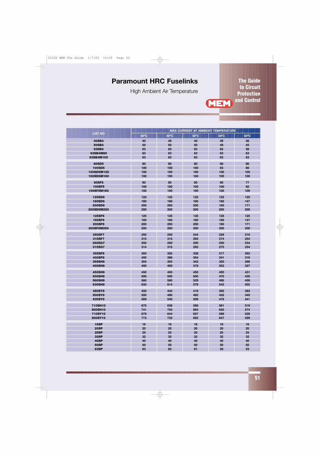
The Guide to Circuit
Protectionand Control
51
Paramount HRC FuselinksHigh Ambient Air Temperature
MAX CURRENT AT AMBIENT TEMPERATURELIST NO
40ºC 45ºC 50ºC 55ºC 60ºC
40SB4 40 40 40 39 3650SB4 50 50 50 49 4563SB4 63 63 63 62 58
63SB4M80 63 63 63 63 6363SB4M100 63 63 63 63 63
80SD5 80 80 80 80 80100SD5 100 100 100 93 86
100SD5M125 100 100 100 100 100100SD5M160 100 100 100 100 100
80SF5 80 80 80 80 77100SF5 100 100 100 100 92
100SF5M160 100 100 100 100 100
125SD6 125 125 125 125 125160SD6 160 160 160 160 147200SD6 200 200 200 185 171
200SD6M250 200 200 200 200 200
125SF6 125 125 125 125 125160SF6 160 160 160 160 147200SF6 200 200 200 185 171
200SF6M250 200 200 200 200 200
250SF7 250 250 244 228 210315SF7 315 315 293 274 254250SG7 250 250 250 250 234315SG7 314 315 293 275 254
355SF8 355 355 338 317 293400SF8 400 386 364 341 316355SH8 355 355 342 320 296400SH8 400 400 378 353 327
450SH9 450 450 450 450 431500SH9 500 500 500 470 435560SH9 560 560 529 495 459630SH9 630 614 579 542 502
450SY9 450 444 419 392 363500SY9 500 490 462 432 340630SY9 569 540 509 476 441
710SH10 670 636 599 561 519800SH10 741 703 663 620 574710SY10 679 644 607 568 526800SY10 773 733 692 647 599
16SP 16 16 16 16 1620SP 20 20 20 20 2025SP 25 25 25 25 2532SP 32 32 32 32 3240SP 40 40 40 40 4050SP 50 50 50 50 5063SP 63 63 61 58 53
31258 MEM The Guide 1/7/03 15:29 Page 53
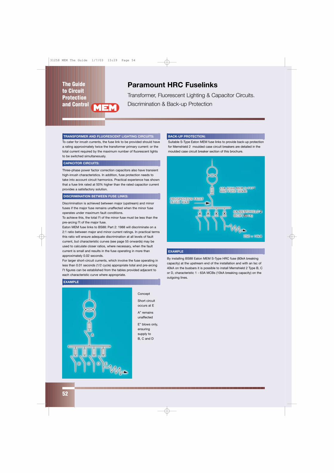
The Guide to CircuitProtectionand Control
52
Paramount HRC FuselinksTransformer, Fluorescent Lighting & Capacitor Circuits.
Discrimination & Back-up Protection
TRANSFORMER AND FLUORESCENT LIGHTING CIRCUITS:
To cater for inrush currents, the fuse link to be provided should have
a rating approximately twice the transformer primary current: or the
total current required by the maximum number of fluorescent lights
to be switched simultaneously.
CAPACITOR CIRCUITS:
Three-phase power factor correction capacitors also have transient
high-inrush characteristics. In addition, fuse protection needs to
take into account circuit harmonics. Practical experience has shown
that a fuse link rated at 50% higher than the rated capacitor current
provides a satisfactory solution.
DISCRIMINATION BETWEEN FUSE LINKS:
Discrimination is achieved between major (upstream) and minor
fuses if the major fuse remains unaffected when the minor fuse
operates under maximum fault conditions.
To achieve this, the total l2t of the minor fuse must be less than the
pre-arcing l2t of the major fuse.
Eaton MEM fuse links to BS88: Part 2: 1988 will discriminate on a
2:1 ratio between major and minor current ratings. In practical terms
this ratio will ensure adequate discrimination at all levels of fault
current, but characteristic curves (see page 55 onwards) may be
used to calculate closer ratios, where necessary, when the fault
current is small and results in the fuse operating in more than
approximately 0.02 seconds.
For larger short-circuit currents, which involve the fuse operating in
less than 0.01 seconds (1/2 cycle) appropriate total and pre-arcing
l2t figures can be established from the tables provided adjacent to
each characteristic curve where appropriate.
EXAMPLE
Concept
Short circuit
occurs at E
A” remains
unaffected
E” blows only,
ensuring
supply to
B, C and D
BACK-UP PROTECTION:
Suitable S-Type Eaton MEM fuse links to provide back-up protection
for Memshield 2 moulded case circuit breakers are detailed in the
moulded case circuit breaker section of this brochure.
EXAMPLE
By installing BS88 Eaton MEM S-Type HRC fuse (80kA breaking
capacity) at the upstream end of the installation and with an Isc of
40kA on the busbars it is possible to install Memshield 2 Type B, C
or D, characteristic 1 - 63A MCBs (10kA breaking capacity) on the
outgoing lines.
31258 MEM The Guide 1/7/03 15:29 Page 54
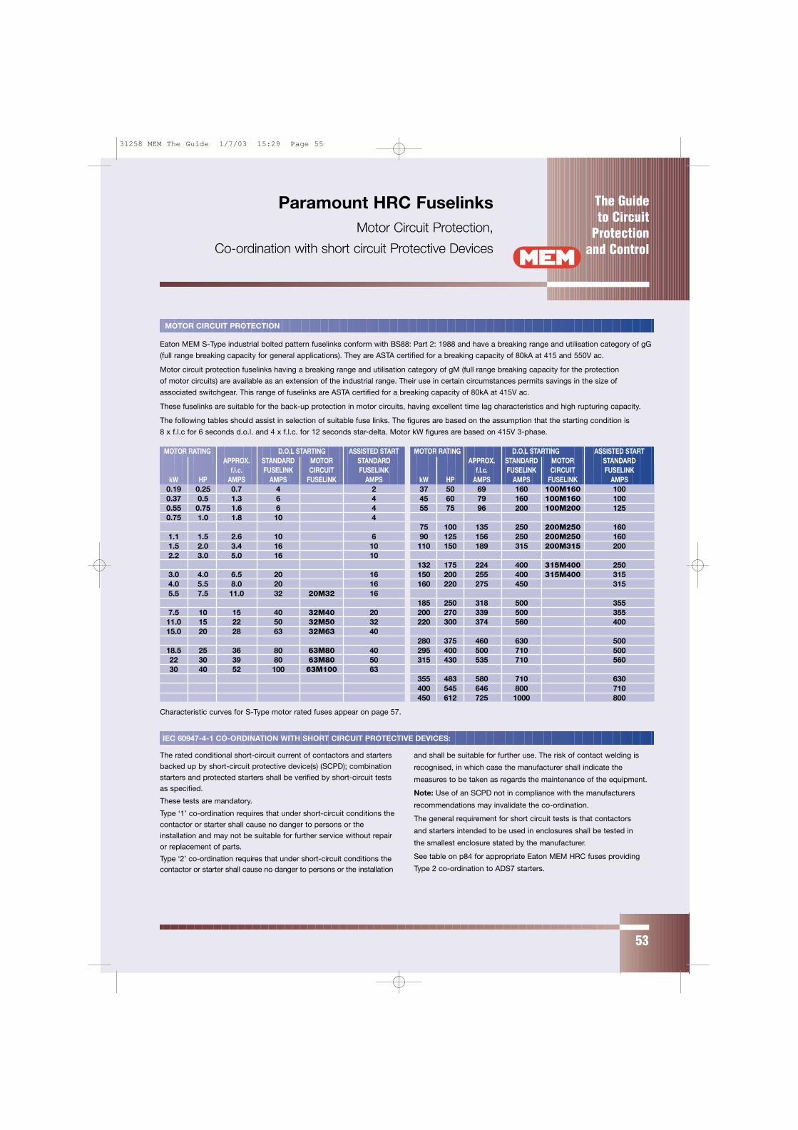
The Guide to Circuit
Protectionand Control
53
Paramount HRC FuselinksMotor Circuit Protection,
Co-ordination with short circuit Protective Devices
MOTOR CIRCUIT PROTECTION
Eaton MEM S-Type industrial bolted pattern fuselinks conform with BS88: Part 2: 1988 and have a breaking range and utilisation category of gG
(full range breaking capacity for general applications). They are ASTA certified for a breaking capacity of 80kA at 415 and 550V ac.
Motor circuit protection fuselinks having a breaking range and utilisation category of gM (full range breaking capacity for the protection
of motor circuits) are available as an extension of the industrial range. Their use in certain circumstances permits savings in the size of
associated switchgear. This range of fuselinks are ASTA certified for a breaking capacity of 80kA at 415V ac.
These fuselinks are suitable for the back-up protection in motor circuits, having excellent time lag characteristics and high rupturing capacity.
The following tables should assist in selection of suitable fuse links. The figures are based on the assumption that the starting condition is
8 x f.l.c for 6 seconds d.o.l. and 4 x f.l.c. for 12 seconds star-delta. Motor kW figures are based on 415V 3-phase.
MOTOR RATING D.O.L STARTING ASSISTED START MOTOR RATING D.O.L STARTING ASSISTED STARTAPPROX. STANDARD MOTOR STANDARD APPROX. STANDARD MOTOR STANDARD
f.l.c. FUSELINK CIRCUIT FUSELINK f.l.c. FUSELINK CIRCUIT FUSELINKkW HP AMPS AMPS FUSELINK AMPS kW HP AMPS AMPS FUSELINK AMPS
0.19 0.25 0.7 4 2 37 50 69 160 100M160 1000.37 0.5 1.3 6 4 45 60 79 160 100M160 1000.55 0.75 1.6 6 4 55 75 96 200 100M200 1250.75 1.0 1.8 10 4
75 100 135 250 200M250 1601.1 1.5 2.6 10 6 90 125 156 250 200M250 1601.5 2.0 3.4 16 10 110 150 189 315 200M315 2002.2 3.0 5.0 16 10
132 175 224 400 315M400 2503.0 4.0 6.5 20 16 150 200 255 400 315M400 3154.0 5.5 8.0 20 16 160 220 275 450 3155.5 7.5 11.0 32 20M32 16
185 250 318 500 3557.5 10 15 40 32M40 20 200 270 339 500 35511.0 15 22 50 32M50 32 220 300 374 560 40015.0 20 28 63 32M63 40
280 375 460 630 50018.5 25 36 80 63M80 40 295 400 500 710 50022 30 39 80 63M80 50 315 430 535 710 56030 40 52 100 63M100 63
355 483 580 710 630400 545 646 800 710450 612 725 1000 800
Characteristic curves for S-Type motor rated fuses appear on page 57.
IEC 60947-4-1 CO-ORDINATION WITH SHORT CIRCUIT PROTECTIVE DEVICES:
The rated conditional short-circuit current of contactors and starters
backed up by short-circuit protective device(s) (SCPD); combination
starters and protected starters shall be verified by short-circuit tests
as specified.
These tests are mandatory.
Type ‘1’ co-ordination requires that under short-circuit conditions the
contactor or starter shall cause no danger to persons or the
installation and may not be suitable for further service without repair
or replacement of parts.
Type ‘2’ co-ordination requires that under short-circuit conditions thecontactor or starter shall cause no danger to persons or the installation
and shall be suitable for further use. The risk of contact welding is
recognised, in which case the manufacturer shall indicate the
measures to be taken as regards the maintenance of the equipment.
Note: Use of an SCPD not in compliance with the manufacturers
recommendations may invalidate the co-ordination.
The general requirement for short circuit tests is that contactors
and starters intended to be used in enclosures shall be tested in
the smallest enclosure stated by the manufacturer.
See table on p84 for appropriate Eaton MEM HRC fuses providing
Type 2 co-ordination to ADS7 starters.
31258 MEM The Guide 1/7/03 15:29 Page 55

The Guide to CircuitProtectionand Control
54
Paramount HRC FuselinksType 2 Co-ordination & ADS7 Starters
The back up fuses quoted give type 2 co-ordination as defined in BSEN 60947-4-1 up to 80kA prospective at 415V 3ph. In selected cases it is
possible to use Memshield 2 miniature circuit breakers to provide back up protection for automatic starters up to 10kA prospective at 415V 3 phase.
STARTER TYPE OVERLOAD RELAY BACK-UP PROTECTION
MAX HRC MEMSHIELD 2 MCBS
CURRENT FUSE, MEM
RANGE A ‘S’ TYPE, A TYPE C TYPE D
Direct-on-line 0.15 – 0.22 2 MCH306 MDH306
380 ... 415V 0.22 – 0.33 2 MCH306 MDH306
3-phase 0.33 – 0.50 2 MCH306 MDH306
0.50 – 0.74 4 MCH306 MDH306
0.74 – 1.11 6 MCH306 MDH306
1.11 – 1.66 6 MCH306 MDH306
1.66 – 2.50 10 MCH306 MDH306
2.50 – 3.70 16 MCH310 MDH306
3.70 – 5.60 20 MCH316 MDH310
5.60 – 8.40 20M25 MCH320 MDH316
8.40 – 11.90 20M32 MCH320 MDH320
11.40 – 16.00 32M40 MCH340 MDH332
16.00 – 23.00 32M50 MCH340 MDH332
23.00 – 33.00 63M80 MCH363 MDH340
Direct-on-line 0.74 – 1.11 6 MCH106 MDH106
220 ... 240V 1.11 – 1.66 6 MCH106 MDH106
single phase 1.66 – 2.50 10 MCH110 MDH106
2.50 – 3.70 16 MCH110 MDH106
3.70 – 5.60 20 MCH116 MDH110
5.60 – 8.40 20M25 MCH120 MDH116
8.40 – 11.90 20M32 MCH132 MDH120
11.40 – 16.00 32M40 MCH150 MDH132
Star-Delta 4.80 – 6.40 16 MCH310 MDH310
380 ... 415V 6.40 – 9.70 20 MCH316 MDH316
3-phase 9.70 – 14.50 20M25 MCH320 MDH320
14.50 – 20.60 20M32 MCH340 MDH332
19.70 – 27.70 32M40 MCH350 MDH332
26.00 – 42.00 32M63 MCH363 –
38.00 – 57.00 63M80 – –
Current range must be selected to include actual motor rated full load current.
STARTER TYPE STARTER SIZEBACK-UP PROTECTION MAXHRC FUSE, MEM ‘S’ TYPE, (A)
Heavy duty contactor 22DSB 63M100
starters. Direct-on-line 30DSB 100M160
380/550V 3-phase 37DSB 100M160
55DSB 200
90DSB 250
Heavy duty contactor 30YSB 63M100
starters. Star-delta 45YSB 63M100
380/550V 3-phase 55YSB 100M160
75YSB 100M160
90YSB 200
31258 MEM The Guide 1/7/03 15:29 Page 56
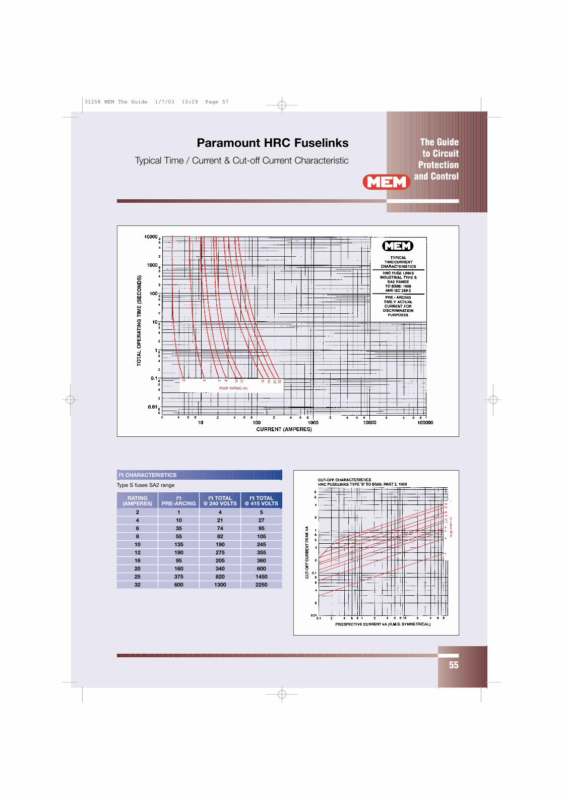
The Guide to Circuit
Protectionand Control
55
Paramount HRC FuselinksTypical Time / Current & Cut-off Current Characteristic
I2t CHARACTERISTICS
Type S fuses SA2 range
RATING I2t I2t TOTAL I2t TOTAL(AMPERES) PRE-ARCING @ 240 VOLTS @ 415 VOLTS
2 1 4 5
4 10 21 27
6 35 74 95
8 55 82 105
10 135 190 245
12 190 275 355
16 95 205 360
20 160 340 600
25 375 820 1450
32 600 1300 2250
31258 MEM The Guide 1/7/03 15:29 Page 57
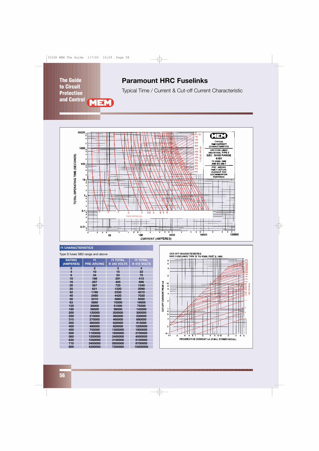
The Guide to CircuitProtectionand Control
56
Paramount HRC FuselinksTypical Time / Current & Cut-off Current Characteristic
l2t CHARACTERISTICS
Type S fuses SB3 range and above
RATING l2t l2t TOTAL l2t TOTAL(AMPERES) PRE-ARCING @ 240 VOLTS @ 415 VOLTS
2 2 3 44 10 15 226 34 53 7510 188 291 41516 207 405 69620 367 720 124025 621 1220 209032 1190 2330 401040 2480 4420 702050 3310 5880 935063 5880 10500 16600125 30000 51000 75500160 58500 99000 145000200 120000 205000 300000250 210000 360000 530000315 270000 460000 680000355 365000 620000 915000400 480000 820000 1200000450 755000 1300000 1900000500 1100000 1850000 2700000560 1200000 2400000 4000000630 1550000 3100000 5150000710 3400000 5850000 8700000800 4200000 7200000 10500000
FUSE RATING (A)
31258 MEM The Guide 1/7/03 15:29 Page 58

The Guide to Circuit
Protectionand Control
57
Paramount HRC FuselinksTypical Time / Current & Cut-off Current Characteristic
l2t CHARACTERISTICS
Type S motor circuit fuses 20M25 – 315M400
RATING l2t l2t TOTAL l2t TOTAL(AMPERES) PRE-ARCING @ 240 VOLTS @ 415 VOLTS
20M25 375 820 1450
20M32 600 1300 2250
32M40 2480 4420 7020
32M50 3310 5880 9350
32M63 5880 10500 16600
100M125 30000 51000 75500
100M160 58500 99000 145000
100M200 120000 205000 300000
200M250 210000 360000 530000
200M315 270000 460000 680000
315M400 480000 820000 1200000
31258 MEM The Guide 1/7/03 15:29 Page 59
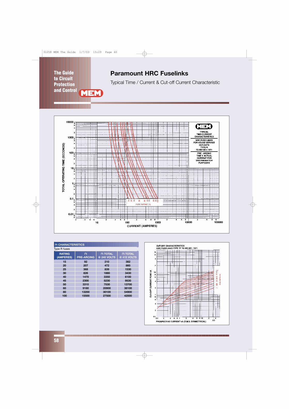
The Guide to CircuitProtectionand Control
58
Paramount HRC FuselinksTypical Time / Current & Cut-off Current Characteristic
l2t CHARACTERISTICS
Type R fuses
RATING l2t l2t TOTAL l2t TOTAL(AMPERES) PRE-ARCING @ 240 VOLTS @ 415 VOLTS
15 92 210 38220 207 472 86025 368 839 153030 826 1880 343040 1470 3350 610045 2300 5230 953050 3310 7530 1370060 9180 20900 3810080 13200 30100 54900100 15500 27500 42000
31258 MEM The Guide 1/7/03 15:29 Page 60
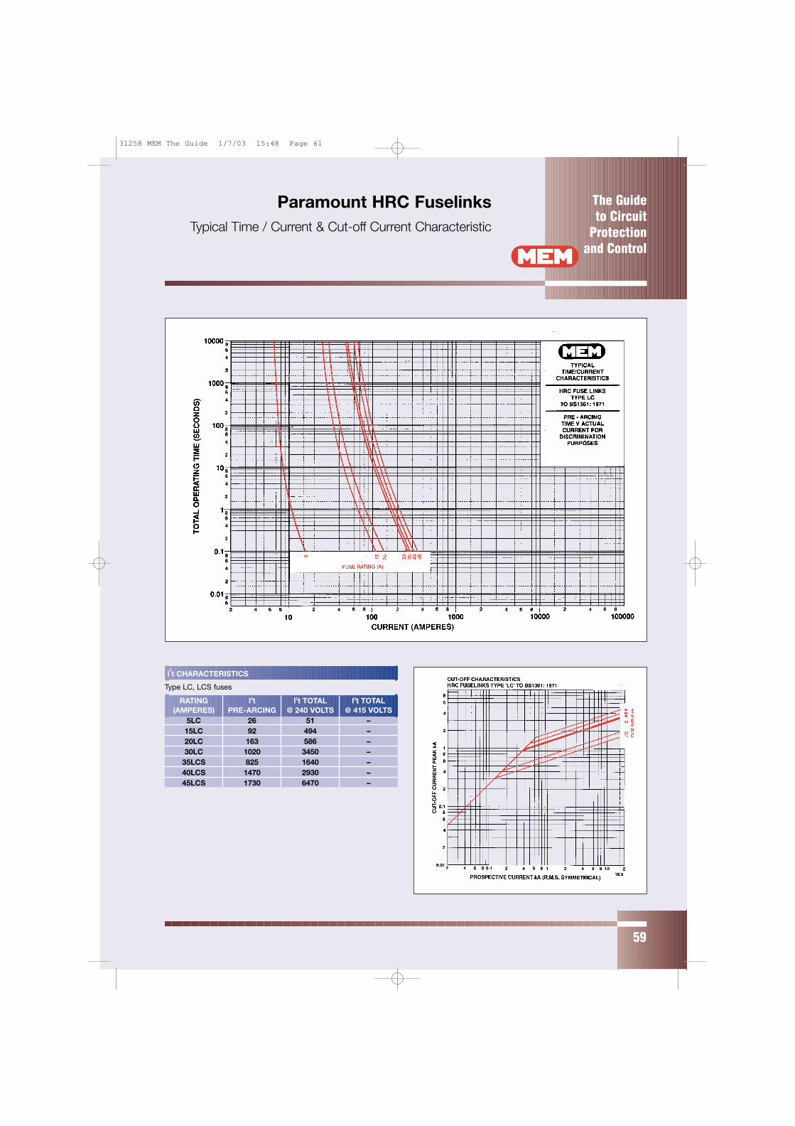
The Guide to Circuit
Protectionand Control
75
Paramount HRC FuselinksTypical Time / Current & Cut-off Current Characteristic
The Guide to Circuit
Protectionand Control
59
Paramount HRC FuselinksTypical Time / Current & Cut-off Current Characteristic
l2t CHARACTERISTICS
Type LC, LCS fuses
RATING l2t l2t TOTAL l2t TOTAL(AMPERES) PRE-ARCING @ 240 VOLTS @ 415 VOLTS
5LC 26 51 –15LC 92 494 –20LC 163 586 –30LC 1020 3450 –
35LCS 825 1640 –40LCS 1470 2930 –45LCS 1730 6470 –
31258 MEM The Guide 1/7/03 15:48 Page 61
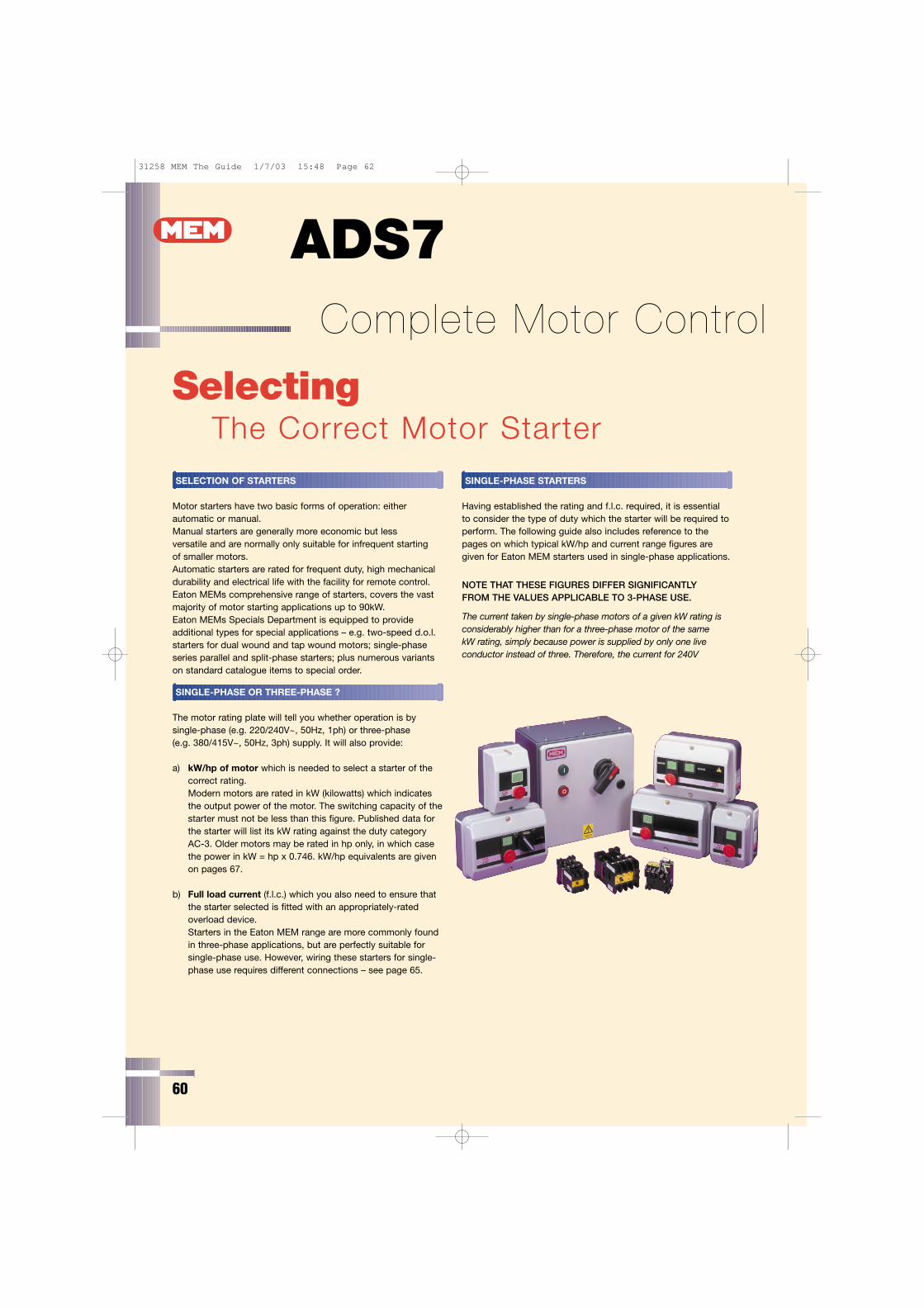
ADS7 Complete Motor Control
60
SelectingThe Correct Motor Starter
SELECTION OF STARTERS
Motor starters have two basic forms of operation: eitherautomatic or manual.Manual starters are generally more economic but less versatile and are normally only suitable for infrequent starting of smaller motors.Automatic starters are rated for frequent duty, high mechanicaldurability and electrical life with the facility for remote control.Eaton MEMs comprehensive range of starters, covers the vastmajority of motor starting applications up to 90kW.Eaton MEMs Specials Department is equipped to provideadditional types for special applications – e.g. two-speed d.o.l.starters for dual wound and tap wound motors; single-phaseseries parallel and split-phase starters; plus numerous variantson standard catalogue items to special order.
SINGLE-PHASE OR THREE-PHASE ?
The motor rating plate will tell you whether operation is bysingle-phase (e.g. 220/240V~, 50Hz, 1ph) or three-phase (e.g. 380/415V~, 50Hz, 3ph) supply. It will also provide:
a) kW/hp of motor which is needed to select a starter of thecorrect rating.Modern motors are rated in kW (kilowatts) which indicatesthe output power of the motor. The switching capacity of thestarter must not be less than this figure. Published data forthe starter will list its kW rating against the duty categoryAC-3. Older motors may be rated in hp only, in which casethe power in kW = hp x 0.746. kW/hp equivalents are givenon pages 67.
b) Full load current (f.l.c.) which you also need to ensure thatthe starter selected is fitted with an appropriately-ratedoverload device.Starters in the Eaton MEM range are more commonly foundin three-phase applications, but are perfectly suitable forsingle-phase use. However, wiring these starters for single-phase use requires different connections – see page 65.
SINGLE-PHASE STARTERS
Having established the rating and f.l.c. required, it is essential to consider the type of duty which the starter will be required toperform. The following guide also includes reference to thepages on which typical kW/hp and current range figures aregiven for Eaton MEM starters used in single-phase applications.
NOTE THAT THESE FIGURES DIFFER SIGNIFICANTLY FROM THE VALUES APPLICABLE TO 3-PHASE USE.
The current taken by single-phase motors of a given kW rating isconsiderably higher than for a three-phase motor of the same kW rating, simply because power is supplied by only one liveconductor instead of three. Therefore, the current for 240V
31258 MEM The Guide 1/7/03 15:48 Page 62
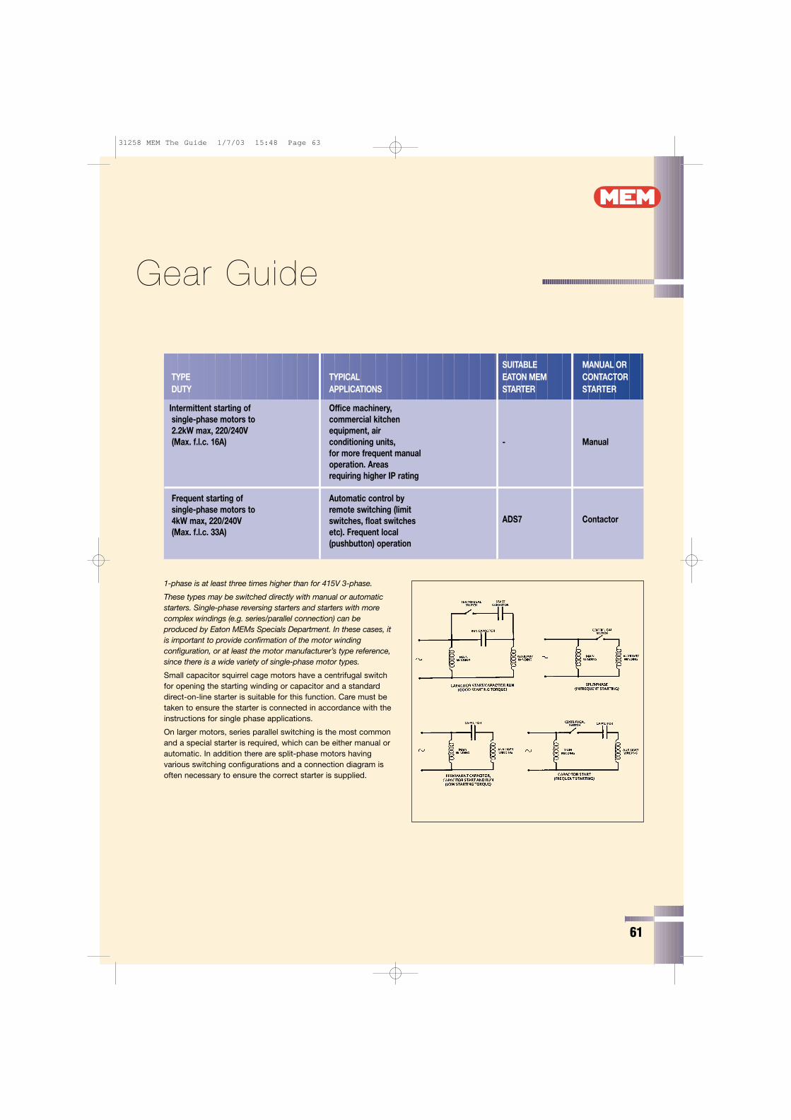
61
Gear Guide
1-phase is at least three times higher than for 415V 3-phase.
These types may be switched directly with manual or automaticstarters. Single-phase reversing starters and starters with morecomplex windings (e.g. series/parallel connection) can beproduced by Eaton MEMs Specials Department. In these cases, itis important to provide confirmation of the motor windingconfiguration, or at least the motor manufacturer’s type reference,since there is a wide variety of single-phase motor types.
Small capacitor squirrel cage motors have a centrifugal switchfor opening the starting winding or capacitor and a standarddirect-on-line starter is suitable for this function. Care must betaken to ensure the starter is connected in accordance with theinstructions for single phase applications.
On larger motors, series parallel switching is the most commonand a special starter is required, which can be either manual orautomatic. In addition there are split-phase motors havingvarious switching configurations and a connection diagram isoften necessary to ensure the correct starter is supplied.
SUITABLE MANUAL ORTYPE TYPICAL EATON MEM CONTACTORDUTY APPLICATIONS STARTER STARTER
Intermittent starting of Office machinery,single-phase motors to commercial kitchen2.2kW max, 220/240V equipment, air(Max. f.l.c. 16A) conditioning units, - Manual
for more frequent manualoperation. Areasrequiring higher IP rating
Frequent starting of Automatic control bysingle-phase motors to remote switching (limit4kW max, 220/240V switches, float switches(Max. f.l.c. 33A) etc). Frequent local
(pushbutton) operation
ADS7 Contactor
31258 MEM The Guide 1/7/03 15:48 Page 63
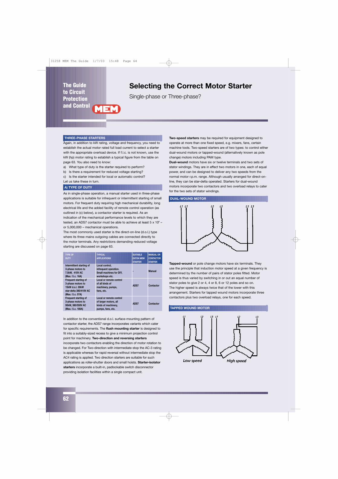
THREE-PHASE STARTERS
Again, in addition to kW rating, voltage and frequency, you need to
establish the actual motor rated full load current to select a starter
with the appropriate overload device. If f.l.c. is not known, use the
kW (hp) motor rating to establish a typical figure from the table on
page 63. You also need to know:
a) What type of duty is the starter required to perform?
b) Is there a requirement for reduced voltage starting?
c) Is the starter intended for local or automatic control?
Let us take these in turn.
A) TYPE OF DUTY
As in single-phase operation, a manual starter used in three-phase
applications is suitable for infrequent or intermittent starting of small
motors. For frequent duty requiring high mechanical durability, long
electrical life and the added facility of remote control operation (as
outlined in (c) below), a contactor starter is required. As an
indication of the mechanical performance levels to which they are
tested, an ADS7 contactor must be able to achieve at least 5 x 10⁶ –
or 5,000,000 – mechanical operations.
The most commonly used starter is the direct-on-line (d.o.l.) type
where its three mains outgoing cables are connected directly to
the motor terminals. Any restrictions demanding reduced voltage
starting are discussed on page 63.
In addition to the conventional d.o.l. surface-mounting pattern of
contactor starter, the ADS7 range incorporates variants which cater
for specific requirements. The flush mounting starter is designed to
fit into a suitably-sized recess to give a minimum projection control
point for machinery. Two-direction and reversing starters
incorporate two contactors enabling the direction of motor rotation to
be changed. For Two-direction with intermediate stop the AC-3 rating
is applicable whereas for rapid reversal without intermediate stop the
AC4 rating is applied. Two direction starters are suitable for such
applications as roller-shutter doors and small hoists. Starter-isolator
starters incorporate a built-in, padlockable switch disconnector
providing isolation facilities within a single compact unit.
Two-speed starters may be required for equipment designed to
operate at more than one fixed speed, e.g. mixers, fans, certain
machine tools. Two-speed starters are of two types: to control either
dual-wound motors or tapped-wound (alternatively known as pole
change) motors including PAM type.
Dual-wound motors have six or twelve terminals and two sets of
stator windings. They are in effect two motors in one, each of equal
power, and can be designed to deliver any two speeds from the
normal motor r.p.m. range. Although usually arranged for direct-on-
line, they can be star-delta operated. Starters for dual-wound
motors incorporate two contactors and two overload relays to cater
for the two sets of stator windings.
Tapped-wound or pole change motors have six terminals. They
use the principle that induction motor speed at a given frequency is
determined by the number of pairs of stator poles fitted. Motor
speed is thus varied by switching in or out an equal number of
stator poles to give 2 or 4, 4 or 8, 6 or 12 poles and so on.
The higher speed is always twice that of the lower with this
arrangement. Starters for tapped wound motors incorporate three
contactors plus two overload relays, one for each speed.
The Guide to CircuitProtectionand Control
62
Selecting the Correct Motor StarterSingle-phase or Three-phase?
TYPE OF TYPICAL SUITABLE MANUAL OR
DUTY APPLICATIONS EATON MEM CONTACTOR
STARTER STARTER
Intermittent starting of Local control,3-phase motors to infrequent operation.7.5kW, 415V AC Small machines for DIY,(Max. f.l.c. 16A) workshops etc.
- Manual
Frequent starting of Local or remote control3-phase motors to of all kinds of15kW d.o.l. 30kW machinery, pumps,star-delta 380/415V AC fans, etc.
ADS7 Contactor
(Max. f.l.c. 57A)Frequent starting of Local or remote control3-phase motors to of larger motors, all90kW, 380/550V AC kinds of machinery,(Max. f.l.c. 180A) pumps, fans, etc.
ADS7 Contactor
DUAL-WOUND MOTOR
TAPPED WOUND MOTOR
31258 MEM The Guide 1/7/03 15:48 Page 64
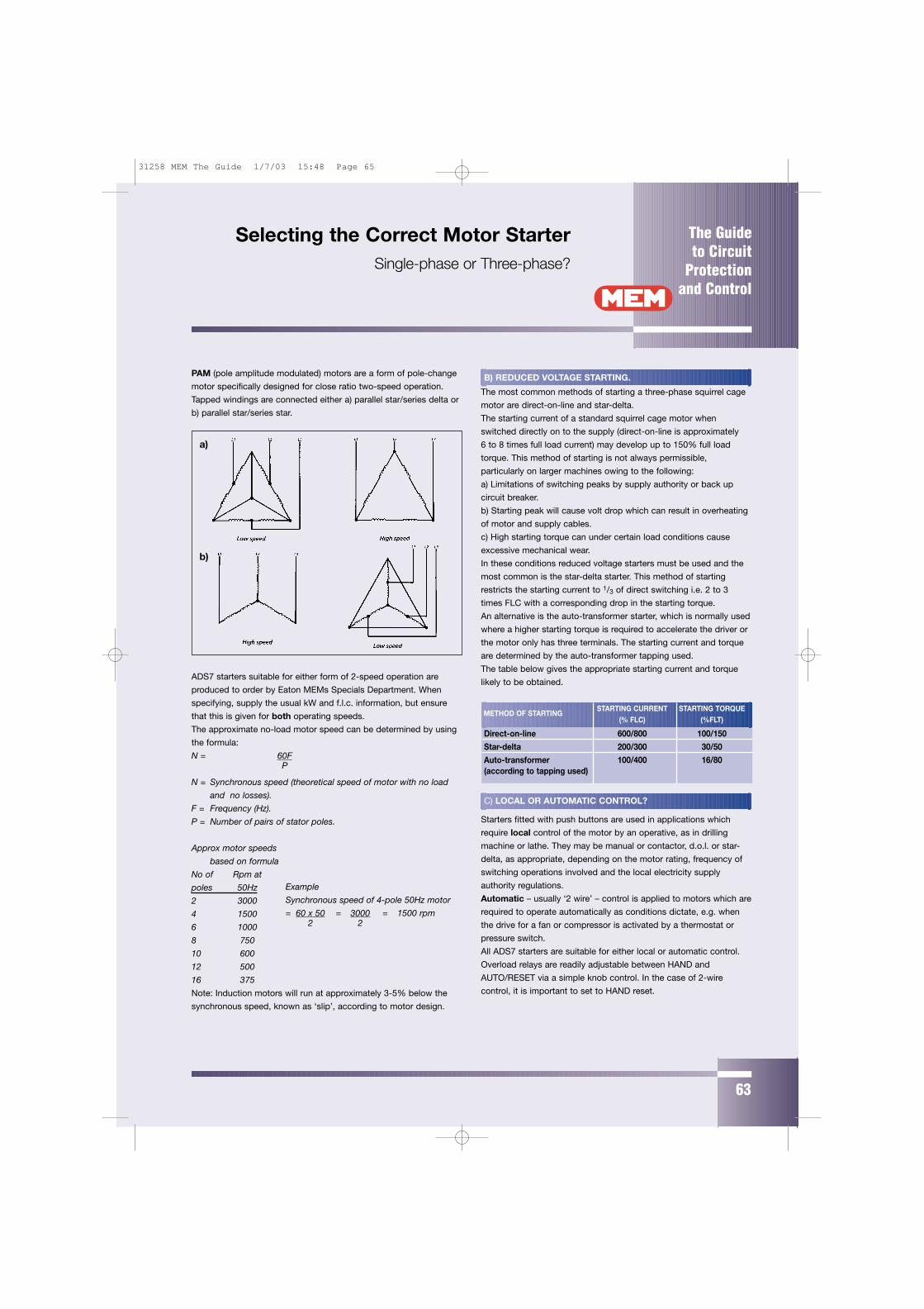
The Guide to Circuit
Protectionand Control
63
Selecting the Correct Motor StarterSingle-phase or Three-phase?
PAM (pole amplitude modulated) motors are a form of pole-change
motor specifically designed for close ratio two-speed operation.
Tapped windings are connected either a) parallel star/series delta or
b) parallel star/series star.
ADS7 starters suitable for either form of 2-speed operation are
produced to order by Eaton MEMs Specials Department. When
specifying, supply the usual kW and f.l.c. information, but ensure
that this is given for both operating speeds.
The approximate no-load motor speed can be determined by using
the formula:
N = 60FP
N = Synchronous speed (theoretical speed of motor with no load
and no losses).
F = Frequency (Hz).
P = Number of pairs of stator poles.
Approx motor speeds
based on formula
No of Rpm at
poles 50Hz
2 3000
4 1500
6 1000
8 750
10 600
12 500
16 375
Note: Induction motors will run at approximately 3-5% below the
synchronous speed, known as ‘slip’, according to motor design.
B) REDUCED VOLTAGE STARTING.
The most common methods of starting a three-phase squirrel cage
motor are direct-on-line and star-delta.
The starting current of a standard squirrel cage motor when
switched directly on to the supply (direct-on-line is approximately
6 to 8 times full load current) may develop up to 150% full load
torque. This method of starting is not always permissible,
particularly on larger machines owing to the following:
a) Limitations of switching peaks by supply authority or back up
circuit breaker.
b) Starting peak will cause volt drop which can result in overheating
of motor and supply cables.
c) High starting torque can under certain load conditions cause
excessive mechanical wear.
In these conditions reduced voltage starters must be used and the
most common is the star-delta starter. This method of starting
restricts the starting current to 1/3 of direct switching i.e. 2 to 3
times FLC with a corresponding drop in the starting torque.
An alternative is the auto-transformer starter, which is normally used
where a higher starting torque is required to accelerate the driver or
the motor only has three terminals. The starting current and torque
are determined by the auto-transformer tapping used.
The table below gives the appropriate starting current and torque
likely to be obtained.
C) LOCAL OR AUTOMATIC CONTROL?
Starters fitted with push buttons are used in applications which
require local control of the motor by an operative, as in drilling
machine or lathe. They may be manual or contactor, d.o.l. or star-
delta, as appropriate, depending on the motor rating, frequency of
switching operations involved and the local electricity supply
authority regulations.
Automatic – usually ‘2 wire’ – control is applied to motors which are
required to operate automatically as conditions dictate, e.g. when
the drive for a fan or compressor is activated by a thermostat or
pressure switch.
All ADS7 starters are suitable for either local or automatic control.
Overload relays are readily adjustable between HAND and
AUTO/RESET via a simple knob control. In the case of 2-wire
control, it is important to set to HAND reset.
METHOD OF STARTINGSTARTING CURRENT STARTING TORQUE
(% FLC) (%FLT)
Direct-on-line 600/800 100/150
Star-delta 200/300 30/50
Auto-transformer 100/400 16/80(according to tapping used)
Example
Synchronous speed of 4-pole 50Hz motor
= 60 x 50 = 3000 = 1500 rpm2 2
a)
b)
31258 MEM The Guide 1/7/03 15:48 Page 65
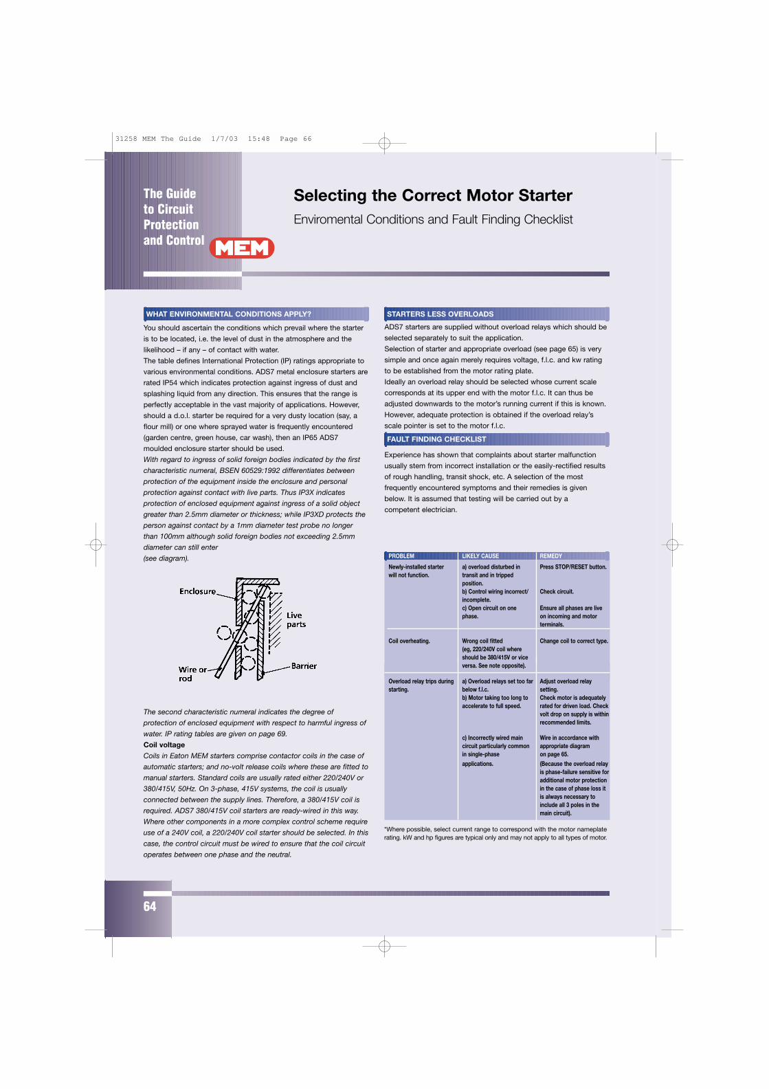
The Guide to CircuitProtectionand Control
64
Selecting the Correct Motor StarterEnviromental Conditions and Fault Finding Checklist
WHAT ENVIRONMENTAL CONDITIONS APPLY?
You should ascertain the conditions which prevail where the starter
is to be located, i.e. the level of dust in the atmosphere and the
likelihood – if any – of contact with water.
The table defines International Protection (IP) ratings appropriate to
various environmental conditions. ADS7 metal enclosure starters are
rated IP54 which indicates protection against ingress of dust and
splashing liquid from any direction. This ensures that the range is
perfectly acceptable in the vast majority of applications. However,
should a d.o.l. starter be required for a very dusty location (say, a
flour mill) or one where sprayed water is frequently encountered
(garden centre, green house, car wash), then an IP65 ADS7
moulded enclosure starter should be used.
With regard to ingress of solid foreign bodies indicated by the first
characteristic numeral, BSEN 60529:1992 differentiates between
protection of the equipment inside the enclosure and personal
protection against contact with live parts. Thus IP3X indicates
protection of enclosed equipment against ingress of a solid object
greater than 2.5mm diameter or thickness; while IP3XD protects the
person against contact by a 1mm diameter test probe no longer
than 100mm although solid foreign bodies not exceeding 2.5mm
diameter can still enter
(see diagram).
The second characteristic numeral indicates the degree of
protection of enclosed equipment with respect to harmful ingress of
water. IP rating tables are given on page 69.
Coil voltage
Coils in Eaton MEM starters comprise contactor coils in the case of
automatic starters; and no-volt release coils where these are fitted to
manual starters. Standard coils are usually rated either 220/240V or
380/415V, 50Hz. On 3-phase, 415V systems, the coil is usually
connected between the supply lines. Therefore, a 380/415V coil is
required. ADS7 380/415V coil starters are ready-wired in this way.
Where other components in a more complex control scheme require
use of a 240V coil, a 220/240V coil starter should be selected. In this
case, the control circuit must be wired to ensure that the coil circuit
operates between one phase and the neutral.
STARTERS LESS OVERLOADS
ADS7 starters are supplied without overload relays which should be
selected separately to suit the application.
Selection of starter and appropriate overload (see page 65) is very
simple and once again merely requires voltage, f.l.c. and kw rating
to be established from the motor rating plate.
Ideally an overload relay should be selected whose current scale
corresponds at its upper end with the motor f.l.c. It can thus be
adjusted downwards to the motor’s running current if this is known.
However, adequate protection is obtained if the overload relay’s
scale pointer is set to the motor f.l.c.
FAULT FINDING CHECKLIST
Experience has shown that complaints about starter malfunction
usually stem from incorrect installation or the easily-rectified results
of rough handling, transit shock, etc. A selection of the most
frequently encountered symptoms and their remedies is given
below. It is assumed that testing will be carried out by a
competent electrician.
PROBLEM LIKELY CAUSE REMEDY
Newly-installed starter a) overload disturbed in Press STOP/RESET button.will not function. transit and in tripped
position.b) Control wiring incorrect/ Check circuit.incomplete.c) Open circuit on one Ensure all phases are livephase. on incoming and motor
terminals.
Coil overheating. Wrong coil fitted Change coil to correct type.(eg, 220/240V coil whereshould be 380/415V or viceversa. See note opposite).
Overload relay trips during a) Overload relays set too far Adjust overload relaystarting. below f.l.c. setting.
b) Motor taking too long to Check motor is adequatelyaccelerate to full speed. rated for driven load. Check
volt drop on supply is withinrecommended limits.
c) Incorrectly wired main Wire in accordance withcircuit particularly common appropriate diagram in single-phase on page 65.applications. (Because the overload relay
is phase-failure sensitive foradditional motor protectionin the case of phase loss itis always necessary toinclude all 3 poles in themain circuit).
*Where possible, select current range to correspond with the motor nameplaterating. kW and hp figures are typical only and may not apply to all types of motor.
31258 MEM The Guide 1/7/03 15:48 Page 66
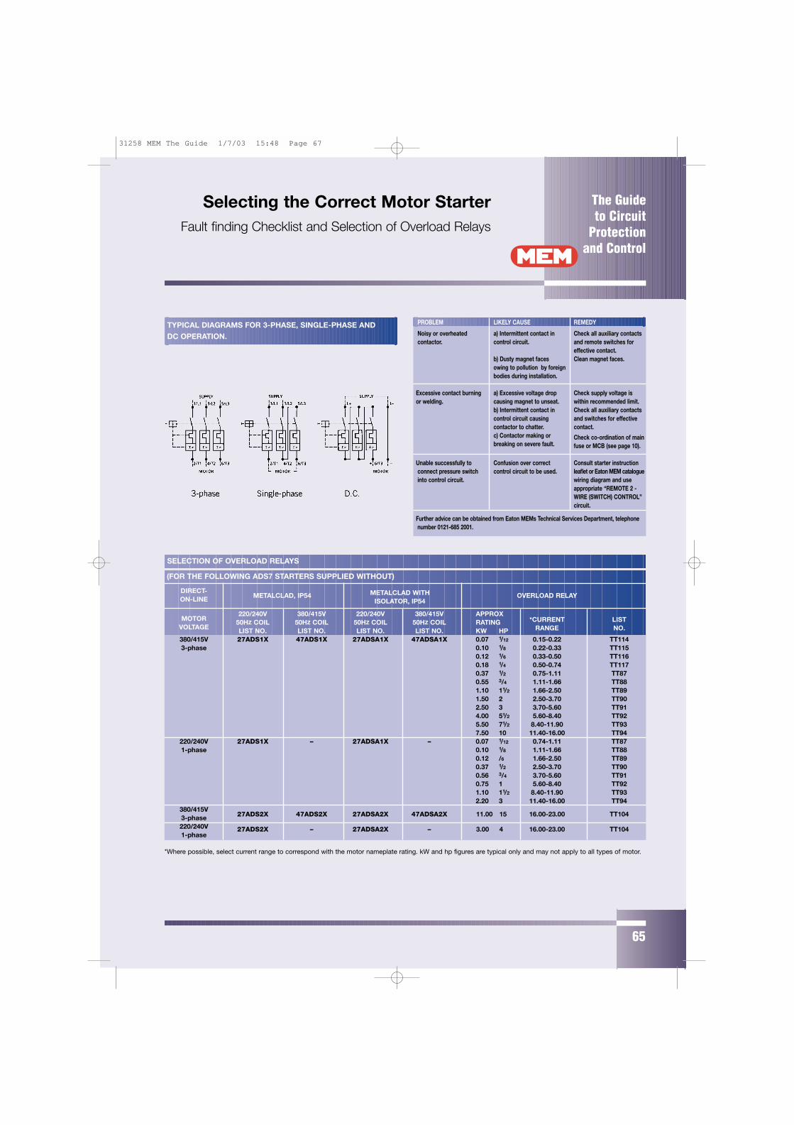
The Guide to Circuit
Protectionand Control
65
Selecting the Correct Motor StarterFault finding Checklist and Selection of Overload Relays
PROBLEM LIKELY CAUSE REMEDY
Noisy or overheated a) Intermittent contact in Check all auxiliary contactscontactor. control circuit. and remote switches for
effective contact.b) Dusty magnet faces Clean magnet faces.owing to pollution by foreignbodies during installation.
Excessive contact burning a) Excessive voltage drop Check supply voltage isor welding. causing magnet to unseat. within recommended limit.
b) Intermittent contact in Check all auxiliary contactscontrol circuit causing and switches for effectivecontactor to chatter. contact.c) Contactor making or Check co-ordination of mainbreaking on severe fault. fuse or MCB (see page 10).
Unable successfully to Confusion over correct Consult starter instructionconnect pressure switch control circuit to be used. leaflet or Eaton MEM catalogueinto control circuit. wiring diagram and use
appropriate “REMOTE 2 -WIRE (SWITCH) CONTROL”circuit.
Further advice can be obtained from Eaton MEMs Technical Services Department, telephonenumber 0121-685 2001.
(FOR THE FOLLOWING ADS7 STARTERS SUPPLIED WITHOUT)
DIRECT-OVERLOAD RELAYON-LINE METALCLAD, IP54 METALCLAD WITH
ISOLATOR, IP54
220/240V 380/415V 220/240V 380/415V APPROXMOTOR 50HZ COIL 50HZ COIL 50HZ COIL 50HZ COIL RATING *CURRENT LIST
VOLTAGE LIST NO. LIST NO. LIST NO. LIST NO. KW HP RANGE NO.
380/415V 27ADS1X 47ADS1X 27ADSA1X 47ADSA1X 0.07 1/12 0.15-0.22 TT1143-phase 0.10 1/8 0.22-0.33 TT115
0.12 1/6 0.33-0.50 TT1160.18 1/4 0.50-0.74 TT1170.37 1/2 0.75-1.11 TT870.55 3/4 1.11-1.66 TT881.10 11/2 1.66-2.50 TT891.50 2 2.50-3.70 TT902.50 3 3.70-5.60 TT914.00 51/2 5.60-8.40 TT925.50 71/2 8.40-11.90 TT937.50 10 11.40-16.00 TT94
220/240V 27ADS1X – 27ADSA1X – 0.07 1/12 0.74-1.11 TT871-phase 0.10 1/8 1.11-1.66 TT88
0.12 /6 1.66-2.50 TT890.37 1/2 2.50-3.70 TT900.56 3/4 3.70-5.60 TT910.75 1 5.60-8.40 TT921.10 11/2 8.40-11.90 TT932.20 3 11.40-16.00 TT94
380/415V27ADS2X 47ADS2X 27ADSA2X 47ADSA2X 11.00 15 16.00-23.00 TT1043-phase
220/240V 27ADS2X – 27ADSA2X – 3.00 4 16.00-23.00 TT1041-phase
*Where possible, select current range to correspond with the motor nameplate rating. kW and hp figures are typical only and may not apply to all types of motor.
TYPICAL DIAGRAMS FOR 3-PHASE, SINGLE-PHASE AND
DC OPERATION.
SELECTION OF OVERLOAD RELAYS
31258 MEM The Guide 1/7/03 15:48 Page 67

The Guide to CircuitProtectionand Control
66
Selecting the Correct Motor StarterSelection of Overload Relays
DIRECT- OVERLOAD RELAYON-LINE
METALCLAD, REVERSING MOULDED, IP65IP54
220/240V 380/415V 220/240V 380/415V APPROXMOTOR 50HZ COIL 50HZ COIL 50HZ COIL 50HZ COIL RATING *CURRENT LIST
VOLTAGE LIST NO. LIST NO. LIST NO. LIST NO. KW HP RANGE NO.380/415V 27ARD1X 47ARD1X 27ADSM1X 47ADSM1X 0.07 1/12 0.15-0.22 TT1143-phase 0.10 1/8 0.22-0.33 TT115
0.12 1/6 0.33-0.50 TT1160.18 1/4 0.50-0.74 TT1170.37 1/2 0.74-1.11 TT870.55 3/4 1.11-1.66 TT881.10 11/2 1.66-2.50 TT891.50 2 2.50-3.70 TT902.50 3 3.70-5.60 TT914.00 51/2 5.60-8.40 TT925.50 71/2 8.40-11.90 TT937.50 10 11.40-16.00 TT94
220/240V 27ARD1X – 27ADSM1X – 0.07 1/12 0.74-1.11 TT871-phase 0.10 1/8 1.11-1.66 TT88
0.12 1/6 1.66-2.50 TT890.37 1/2 2.50-3.70 TT900.56 3/4 3.70-5.60 TT910.75 1 5.60-8.40 TT921.10 11/2 8.40-11.90 TT932.20 3 11.40-16.00 TT94
380/415V 27ARD2X 47ARD2X 27ADSM2X 47ADSM2X 11.00 15 16.00-23.00 TT104
3-phase220/240V 27ARD2X – 27ADSM2X – 3.00 4 16.00-23.00 TT1041-phase
STAR-DELTA OVERLOAD RELAYMETALCLAD, IP54, METALCLAD, IP54
220/240V 380/415V 220/240V 380/415V ApproxMOTOR 50HZ COIL 50HZ COIL 50HZ COIL 50HZ COIL RATING *CURRENT LIST
VOLTAGE LIST NO. LIST NO. LIST NO. LIST NO. KW HP RANGE NO.
380/415V 27SDA2X 47SDA2X 27SDA3X 47SDA3X 3.00 4 4.30-6.40 TT973-phase 5.00 61/2 6.40-9.70 TT98
7.50 10 9.70-14.50 TT9910.00 13 14.50-20.60 TT10015.00 20 19.70-27.70 TT10122.00 30 26.00-38.00 TT10230.00 40 38.00-57.00 TT103
*Where possible, select current range to correspond with the motor nameplate rating. kW and hp figures are typical only and may not apply to all types of motor.
31258 MEM The Guide 1/7/03 15:48 Page 68
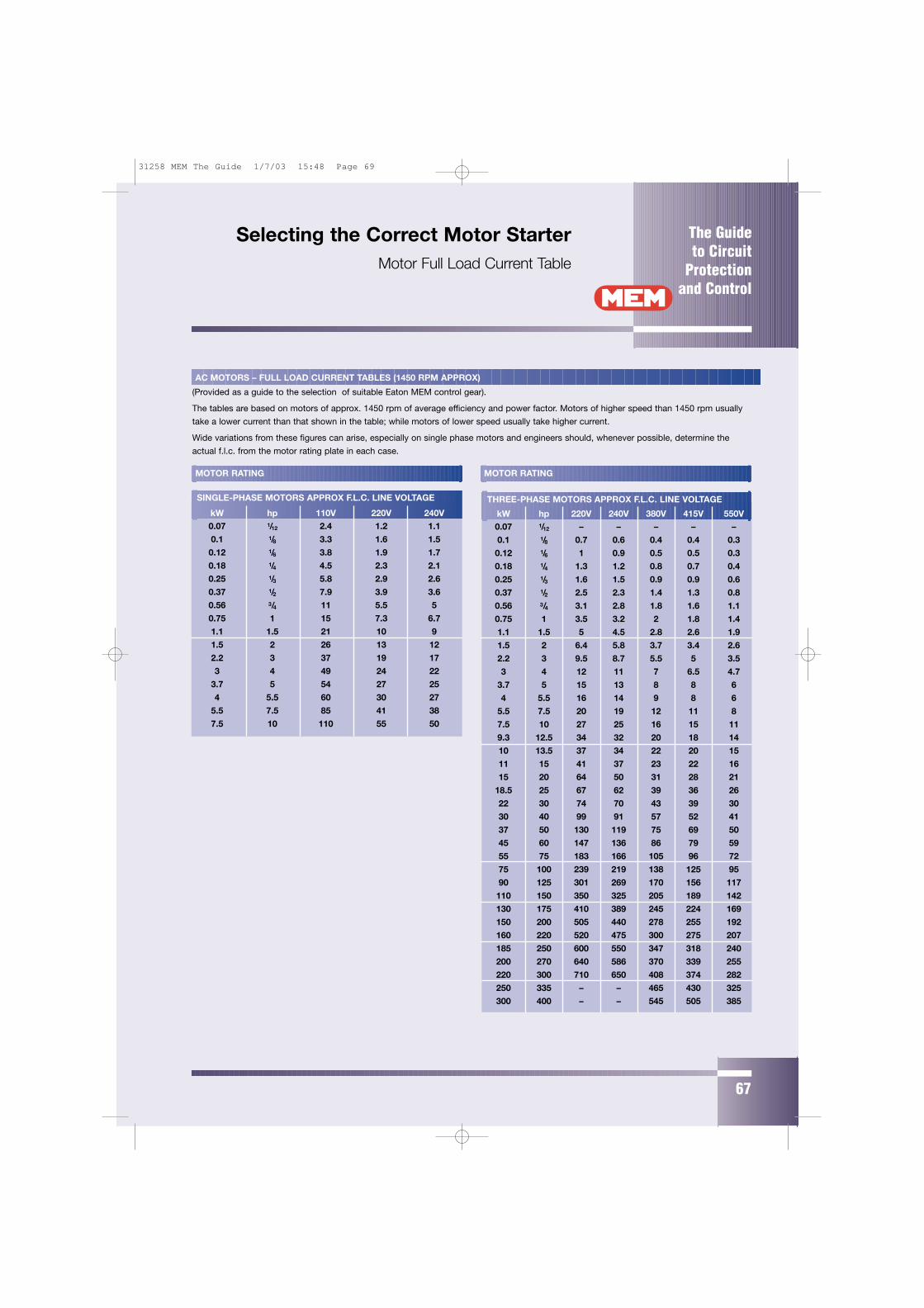
The Guide to Circuit
Protectionand Control
67
Selecting the Correct Motor StarterMotor Full Load Current Table
THREE-PHASE MOTORS APPROX F.L.C. LINE VOLTAGE
kW hp 220V 240V 380V 415V 550V0.07 1/12 – – – – –
0.1 1/8 0.7 0.6 0.4 0.4 0.3
0.12 1/6 1 0.9 0.5 0.5 0.3
0.18 1/4 1.3 1.2 0.8 0.7 0.4
0.25 1/3 1.6 1.5 0.9 0.9 0.6
0.37 1/2 2.5 2.3 1.4 1.3 0.8
0.56 3/4 3.1 2.8 1.8 1.6 1.1
0.75 1 3.5 3.2 2 1.8 1.4
1.1 1.5 5 4.5 2.8 2.6 1.9
1.5 2 6.4 5.8 3.7 3.4 2.6
2.2 3 9.5 8.7 5.5 5 3.5
3 4 12 11 7 6.5 4.7
3.7 5 15 13 8 8 6
4 5.5 16 14 9 8 6
5.5 7.5 20 19 12 11 8
7.5 10 27 25 16 15 11
9.3 12.5 34 32 20 18 14
10 13.5 37 34 22 20 15
11 15 41 37 23 22 16
15 20 64 50 31 28 21
18.5 25 67 62 39 36 26
22 30 74 70 43 39 30
30 40 99 91 57 52 41
37 50 130 119 75 69 50
45 60 147 136 86 79 59
55 75 183 166 105 96 72
75 100 239 219 138 125 95
90 125 301 269 170 156 117
110 150 350 325 205 189 142
130 175 410 389 245 224 169
150 200 505 440 278 255 192
160 220 520 475 300 275 207
185 250 600 550 347 318 240
200 270 640 586 370 339 255
220 300 710 650 408 374 282
250 335 – – 465 430 325
300 400 – – 545 505 385
MOTOR RATING MOTOR RATING
AC MOTORS – FULL LOAD CURRENT TABLES (1450 RPM APPROX)
(Provided as a guide to the selection of suitable Eaton MEM control gear).
The tables are based on motors of approx. 1450 rpm of average efficiency and power factor. Motors of higher speed than 1450 rpm usually
take a lower current than that shown in the table; while motors of lower speed usually take higher current.
Wide variations from these figures can arise, especially on single phase motors and engineers should, whenever possible, determine the
actual f.l.c. from the motor rating plate in each case.
SINGLE-PHASE MOTORS APPROX F.L.C. LINE VOLTAGE
kW hp 110V 220V 240V0.07 1/12 2.4 1.2 1.1
0.1 1/8 3.3 1.6 1.5
0.12 1/6 3.8 1.9 1.7
0.18 1/4 4.5 2.3 2.1
0.25 1/3 5.8 2.9 2.6
0.37 1/2 7.9 3.9 3.6
0.56 3/4 11 5.5 5
0.75 1 15 7.3 6.7
1.1 1.5 21 10 9
1.5 2 26 13 12
2.2 3 37 19 17
3 4 49 24 22
3.7 5 54 27 25
4 5.5 60 30 27
5.5 7.5 85 41 38
7.5 10 110 55 50
31258 MEM The Guide 1/7/03 15:48 Page 69
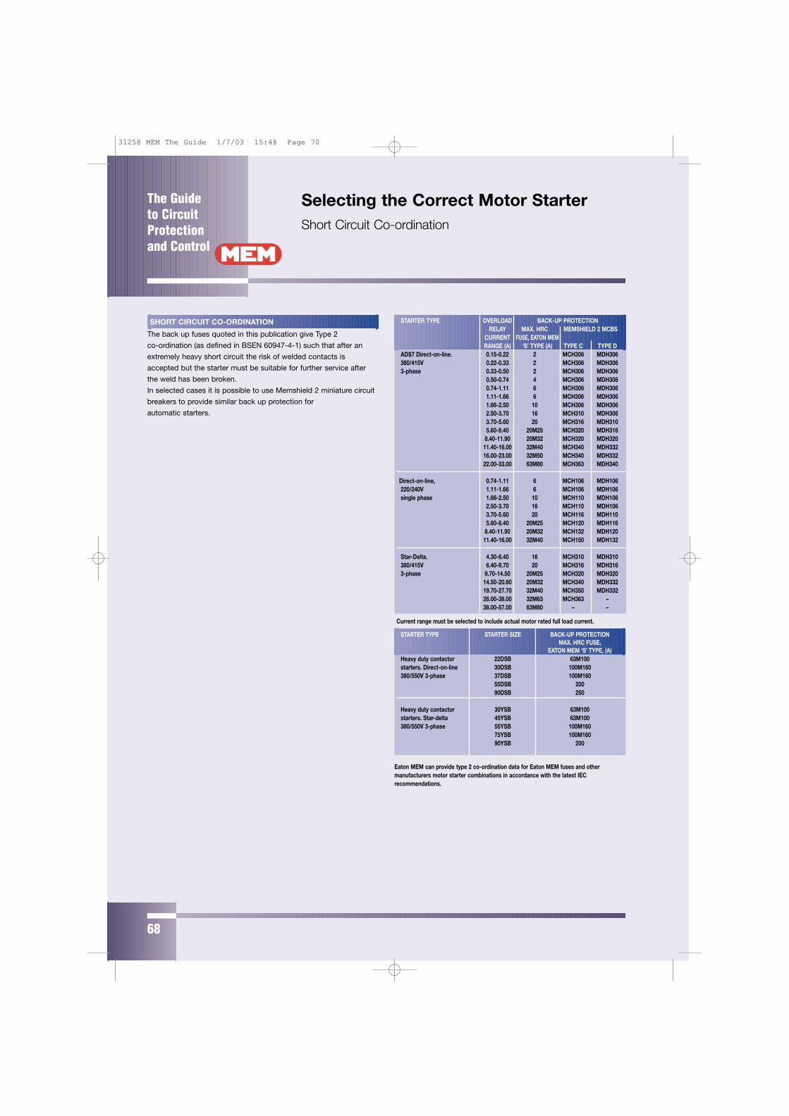
The Guide to CircuitProtectionand Control
68
Selecting the Correct Motor StarterShort Circuit Co-ordination
SHORT CIRCUIT CO-ORDINATION
The back up fuses quoted in this publication give Type 2
co-ordination (as defined in BSEN 60947-4-1) such that after an
extremely heavy short circuit the risk of welded contacts is
accepted but the starter must be suitable for further service after
the weld has been broken.
In selected cases it is possible to use Memshield 2 miniature circuit
breakers to provide similar back up protection for
automatic starters.
STARTER TYPE OVERLOAD BACK-UP PROTECTIONRELAY MAX. HRC MEMSHIELD 2 MCBS
CURRENT FUSE, EATON MEMRANGE (A) ‘S’ TYPE (A) TYPE C TYPE D
ADS7 Direct-on-line. 0.15-0.22 2 MCH306 MDH306380/415V 0.22-0.33 2 MCH306 MDH3063-phase 0.33-0.50 2 MCH306 MDH306
0.50-0.74 4 MCH306 MDH3060.74-1.11 6 MCH306 MDH3061.11-1.66 6 MCH306 MDH3061.66-2.50 10 MCH306 MDH3062.50-3.70 16 MCH310 MDH3063.70-5.60 20 MCH316 MDH3105.60-8.40 20M25 MCH320 MDH316
8.40-11.90 20M32 MCH320 MDH32011.40-16.00 32M40 MCH340 MDH33216.00-23.00 32M50 MCH340 MDH33222.00-33.00 63M80 MCH363 MDH340
Direct-on-line, 0.74-1.11 6 MCH106 MDH106220/240V 1.11-1.66 6 MCH106 MDH106single phase 1.66-2.50 10 MCH110 MDH106
2.50-3.70 16 MCH110 MDH1063.70-5.60 20 MCH116 MDH1105.60-8.40 20M25 MCH120 MDH116
8.40-11.90 20M32 MCH132 MDH12011.40-16.00 32M40 MCH150 MDH132
Star-Delta. 4.30-6.40 16 MCH310 MDH310380/415V 6.40-9.70 20 MCH316 MDH3163-phase 9.70-14.50 20M25 MCH320 MDH320
14.50-20.60 20M32 MCH340 MDH33219.70-27.70 32M40 MCH350 MDH33226.00-38.00 32M63 MCH363 –38.00-57.00 63M80 – –
Current range must be selected to include actual motor rated full load current.
STARTER TYPE STARTER SIZE BACK-UP PROTECTIONMAX. HRC FUSE,
EATON MEM ‘S’ TYPE, (A)Heavy duty contactor 22DSB 63M100starters. Direct-on-line 30DSB 100M160380/550V 3-phase 37DSB 100M160
55DSB 20090DSB 250
Heavy duty contactor 30YSB 63M100starters. Star-delta 45YSB 63M100380/550V 3-phase 55YSB 100M160
75YSB 100M16090YSB 200
Eaton MEM can provide type 2 co-ordination data for Eaton MEM fuses and othermanufacturers motor starter combinations in accordance with the latest IECrecommendations.
31258 MEM The Guide 1/7/03 15:48 Page 70
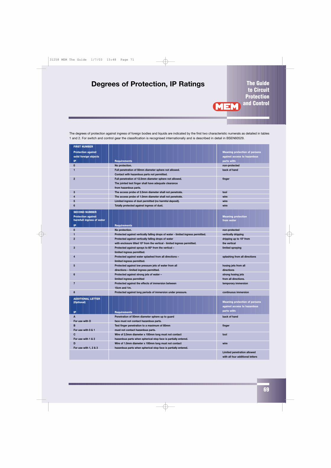
The Guide to Circuit
Protectionand Control
69
Degrees of Protection, IP Ratings
The degrees of protection against ingress of foreign bodies and liquids are indicated by the first two characteristic numerals as detailed in tables
1 and 2. For switch and control gear the classification is recognised internationally and is described in detail in BSEN60529.
FIRST NUMBER
Protection against Meaning protection of persons
solid foreign objects against access to hazardous
IP Requirements parts with:
0 No protection. non-protected
1 Full penetration of 50mm diameter sphere not allowed. back of hand
Contact with hazardous parts not permitted.
2 Full penetration of 12.5mm diameter sphere not allowed. finger
The jointed test finger shall have adequate clearance
from hazardous parts.
3 The access probe of 2.5mm diameter shall not penetrate. tool
4 The access probe of 1.0mm diameter shall not penetrate. wire
5 Limited ingress of dust permitted (no harmful deposit). wire
6 Totally protected against ingress of dust. wire
SECOND NUMBER
Protection against Meaning protectionharmfull ingress of water from water
IP Requirements
0 No protection. non-protected
1 Protected against vertically falling drops of water - limited ingress permitted. vertically dripping
2 Protected against vertically falling drops of water dripping up to 15º from
with enclosure tilted 15º from the vertical - limited ingress permitted. the vertical
3 Protected against sprays to 60º from the vertical – limited spraying
limited ingress permitted.
4 Protected against water splashed from all directions – splashing from all directions
limited ingress permitted.
5 Protected against low pressure jets of water from all hosing jets from all
directions – limited ingress permitted. directions
6 Protected against strong jets of water – strong hosing jets
limited ingress permitted from all directions.
7 Protected against the effects of immersion between temporary immersion
15cm and 1m.
8 Protected against long periods of immersion under pressure. continuous immersion
ADDITIONAL LETTER(Optional) Meaning protection of persons
against access to hazardous
IP Requirements parts with:
A Penetration of 50mm diameter sphere up to guard back of hand
For use with O face must not contact hazardous parts.
B Test finger penetration to a maximum of 80mm finger
For use with 0 & 1 must not contact hazardous parts.
C Wire of 2.5mm diameter x 100mm long must not contact tool
For use with 1 & 2 hazardous parts when spherical stop face is partially entered.
D Wire of 1.0mm diameter x 100mm long must not contact wire
For use with 1, 2 & 3 hazardous parts when spherical stop face is partially entered.
Limited penetration allowed
with all four additional letters
31258 MEM The Guide 1/7/03 15:48 Page 71
MEM Circuit Protection & ControlEaton Electric LimitedReddings LaneBirmingham B11 3EZTel: 0121 685 2100Fax: 0121 706 2012Sales Support 0121-685 2000Technical Support 0121-685 2001Fax for Orders & Sales Enquiries 0121-706 9996Central Quotation Service: 0121 326 2541Email: [email protected]
Eaton Electric Company Ltd595 Pracha-Uthit Road,(Ramkhamhaeng 39)Wangthonglang Bangkok,10310, ThailandTel: (66) 2 935 6470Fax: (66) 2 935 6478
Eaton Electric Switchgear (AsiaPacific) Pte Ltd50 Genting Lane #03-05, Cideco Industrial Complex, Singapore 349558Tel: (65) 67410737Fax: (65) 67410738
Eaton Electric LtdPO Box 1993Doha, QatarTel: (974) 4654792Fax: (974) 4654792
Eaton Innovative Technology15470 Flight Path Drive,Brooksville, Florida 34604, USATel: 001 352 799 0713Fax: 001 352 796 0316
Bell - A Division of Eaton Electric Systems Pty Ltd10 Kent Road, Mascot,NSW 2020, AustraliaTel: (61) 2 9693 9333Fax: (61) 2 9693 1258
Eaton Electric Switchgear Sdn. BhdPO Box 162, 12720 Butterworth,Seberang Perai, MalaysiaTel: (60) 4 3907566Fax: (60) 4 3990746
Eaton Electric LtdPO Box 30838, Dubai, United Arab EmiratesTel: (971) 4 2660187 Fax: (971) 4 2693774
Eaton HolecPO Box 23, 7550 AA HengeloThe NetherlandsTel: (31) 74 246 9111Fax: (31) 74 246 4444
Eaton Electric LtdEast African Regional Office1st Floor, Liaison House, State House Avenue, PO Box 48010, Nairobi, KenyaTel: (254 2) 2719230/2718859Fax: (254 2) 2711969
Eaton Electric & EngineeringServices Ltd6th Floor, Mtl Warehouse, Phase 11 Berth One, Kwai Chung Container TerminalKwai Chung, N.T. Hong KongTel: (852) 2942 4388Fax: (852) 2615 2289
Eaton ElekAM Alten Bach 18,41470 Neuss,GermanyTel: (49) 21 37 7810 Fax: (49) 21 37 781152
TOTAL PROJECT MANAGEMENT,MV & LV SWITCHBOARDS, PFC & TVSS:
MEM Circuit Protection & ControlPremier Street, Birmingham B7 5TQTel: 0121 326 2500Fax: 0121 327 0656Fax: Estimation: 0121 326 2541Fax: Project Management: 0121 326 2567
INDUSTRIAL SWITCHGEAR, CONTROL GEAR, CIRCUITBREAKER SYSTEMS AND BUSBAR TRUNKING:
MEM Circuit Protection & ControlReddings Lane, Birmingham B11 3EZTel: 0121 685 2100Fax: 0121 706 2012Busbar Trunking Tel: 0121 707 9797Fax: 0121 707 4840
ELECTRICAL ACCESSORIES ANDDOMESTIC SWITCHGEAR:
MEM 250 Whitegate, Broadway,Chadderton, Oldham, Lancs. OL9 9QGTel: 0161 652 1111Fax: 0161 626 1709
South West, Midlands,North & Scotland Sales OfficeReddings LaneTyseleyBirmingham B11 3EZTel: 0121 685 2155Fax: 0121 685 2191
South East Regional Sales OfficeSuite 8Ensign HouseAdmiral’s WayLondon E14 9XQTel: 0207 987 8602Fax: 0207 987 4632
UK MANUFACTURING
UK REGIONAL SALES OFFICES
INTERNATIONAL LOCATIONS
CAT 865/06/03
31258 MEM The Guide 1/7/03 15:48 Page 72