Embed Size (px)
Citation preview
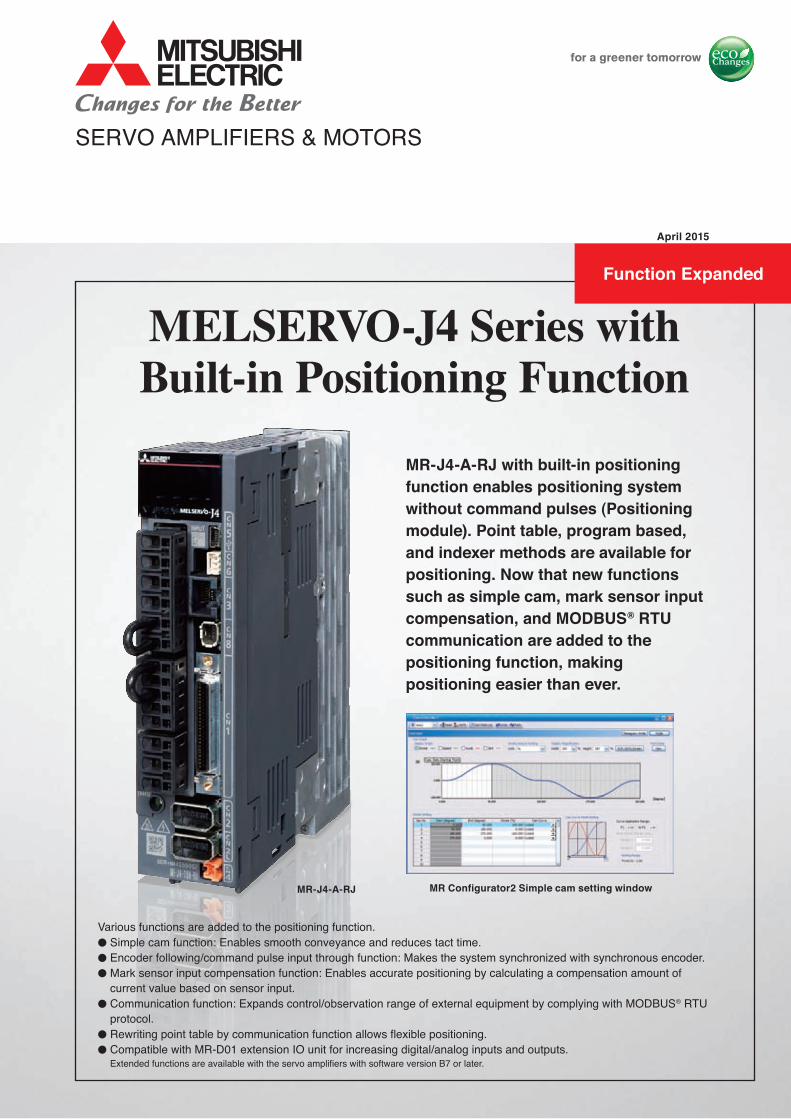
MR Configurator2 Simple cam setting window
MR-J4-A-RJ with built-in positioning function enables positioning system without command pulses (Positioning module). Point table, program based, and indexer methods are available for positioning. Now that new functions such as simple cam, mark sensor input compensation, and MODBUS® RTU communication are added to the positioning function, making positioning easier than ever.
MR-J4-A-RJ
MELSERVO-J4 Series withBuilt-in Positioning Function
SERVO AMPLIFIERS & MOTORS
Various functions are added to the positioning function.● Simple cam function: Enables smooth conveyance and reduces tact time.● Encoder following/command pulse input through function: Makes the system synchronized with synchronous encoder.● Mark sensor input compensation function: Enables accurate positioning by calculating a compensation amount of
current value based on sensor input.● Communication function: Expands control/observation range of external equipment by complying with MODBUS® RTU
protocol.● Rewriting point table by communication function allows flexible positioning. ● Compatible with MR-D01 extension IO unit for increasing digital/analog inputs and outputs. Extended functions are available with the servo amplifiers with software version B7 or later.
April 2015
Function Expanded
1
MR-J4-A-RJ Built-in Positioning Function
Rotary servo motor, linear servo motor, and direct drive servo motor are compatible.
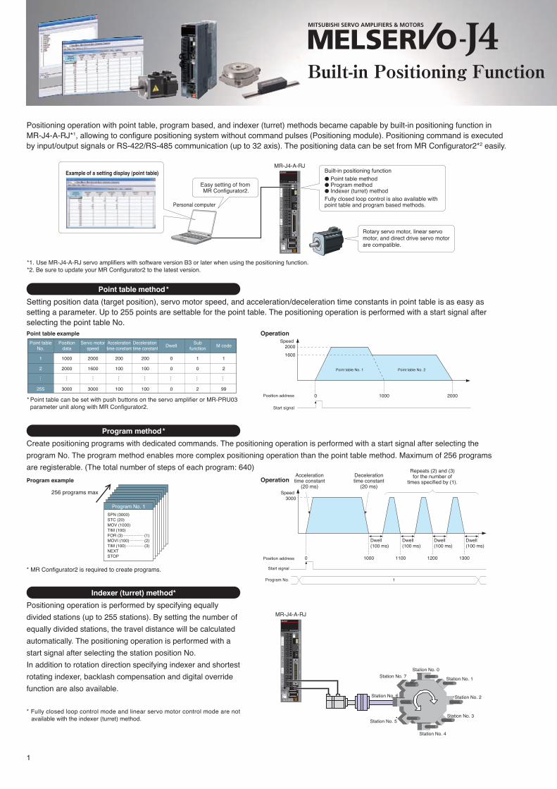
Positioning operation with point table, program based, and indexer (turret) methods became capable by built-in positioning function in MR-J4-A-RJ*1, allowing to configure positioning system without command pulses (Positioning module). Positioning command is executed by input/output signals or RS-422/RS-485 communication (up to 32 axis). The positioning data can be set from MR Configurator2*2 easily.
Easy setting of from MR Configurator2.
Built-in positioning function ● Point table method● Program method● Indexer (turret) methodFully closed loop control is also available with point table and program based methods.
MR-J4-A-RJ
MR-J4-A-RJ
Station No. 0
Station No. 1
Station No. 2
Station No. 3
Station No. 4
Station No. 5
Station No. 6
Station No. 7
*1. Use MR-J4-A-RJ servo amplifiers with software version B3 or later when using the positioning function.*2. Be sure to update your MR Configurator2 to the latest version.
* Point table can be set with push buttons on the servo amplifier or MR-PRU03 parameter unit along with MR Configurator2.
Personal computer
Example of a setting display (point table)
Setting position data (target position), servo motor speed, and acceleration/deceleration time constants in point table is as easy as setting a parameter. Up to 255 points are settable for the point table. The positioning operation is performed with a start signal after selecting the point table No.
Point table method*
Create positioning programs with dedicated commands. The positioning operation is performed with a start signal after selecting the program No. The program method enables more complex positioning operation than the point table method. Maximum of 256 programs are registerable. (The total number of steps of each program: 640)
Program method*
Positioning operation is performed by specifying equally divided stations (up to 255 stations). By setting the number of equally divided stations, the travel distance will be calculated automatically. The positioning operation is performed with a start signal after selecting the station position No.In addition to rotation direction specifying indexer and shortest rotating indexer, backlash compensation and digital override function are also available.
* Fully closed loop control mode and linear servo motor control mode are not available with the indexer (turret) method.
* MR Configurator2 is required to create programs.
Indexer (turret) method*
Program example
256 programs max
SPN (3000)STC (20)MOV (1000)TIM (100)FOR (3) (1)MOVI (100) (2)TIM (100) (3)NEXTSTOP
Point table example OperationSpeed
20001600
1000 20000Position address
Point table No. 1 Point table No. 2
Start signal
Point tableNo.
Positiondata
Servo motorspeed
Accelerationtime constant
Deceleration time constant
SubfunctionDwell M code
1
2
255
1000
2000
3000
2000
1600
3000
200
100
100
200
100
100
0
0
0
1
0
2
1
2
99
Program No. 13000
Start signal
Operation
Speed
Accelerationtime constant
(20 ms)
Decelerationtime constant
(20 ms)
Repeats (2) and (3)for the number of
times specified by (1).
1Program No.
Position address
Dwell (100 ms)
0 1100 1200 13001000
Dwell (100 ms)
Dwell (100 ms)
Dwell (100 ms)
Built-in Positioning Function
2
MR-J4-A-RJ Built-in Positioning Function
Rotary servo motor, linear servo motor, and direct drive servo motor are compatible.
Positioning operation with point table, program based, and indexer (turret) methods became capable by built-in positioning function in MR-J4-A-RJ*1, allowing to configure positioning system without command pulses (Positioning module). Positioning command is executed by input/output signals or RS-422/RS-485 communication (up to 32 axis). The positioning data can be set from MR Configurator2*2 easily.
Easy setting of from MR Configurator2.
Built-in positioning function ● Point table method● Program method● Indexer (turret) methodFully closed loop control is also available with point table and program based methods.
MR-J4-A-RJ
MR-J4-A-RJ
Station No. 0
Station No. 1
Station No. 2
Station No. 3
Station No. 4
Station No. 5
Station No. 6
Station No. 7
*1. Use MR-J4-A-RJ servo amplifiers with software version B3 or later when using the positioning function.*2. Be sure to update your MR Configurator2 to the latest version.
* Point table can be set with push buttons on the servo amplifier or MR-PRU03 parameter unit along with MR Configurator2.
Personal computer
Example of a setting display (point table)
Setting position data (target position), servo motor speed, and acceleration/deceleration time constants in point table is as easy as setting a parameter. Up to 255 points are settable for the point table. The positioning operation is performed with a start signal after selecting the point table No.
Point table method*
Create positioning programs with dedicated commands. The positioning operation is performed with a start signal after selecting the program No. The program method enables more complex positioning operation than the point table method. Maximum of 256 programs are registerable. (The total number of steps of each program: 640)
Program method*
Positioning operation is performed by specifying equally divided stations (up to 255 stations). By setting the number of equally divided stations, the travel distance will be calculated automatically. The positioning operation is performed with a start signal after selecting the station position No.In addition to rotation direction specifying indexer and shortest rotating indexer, backlash compensation and digital override function are also available.
* Fully closed loop control mode and linear servo motor control mode are not available with the indexer (turret) method.
* MR Configurator2 is required to create programs.
Indexer (turret) method*
Program example
256 programs max
SPN (3000)STC (20)MOV (1000)TIM (100)FOR (3) (1)MOVI (100) (2)TIM (100) (3)NEXTSTOP
Point table example OperationSpeed
20001600
1000 20000Position address
Point table No. 1 Point table No. 2
Start signal
Point tableNo.
Positiondata
Servo motorspeed
Accelerationtime constant
Deceleration time constant
SubfunctionDwell M code
1
2
255
1000
2000
3000
2000
1600
3000
200
100
100
200
100
100
0
0
0
1
0
2
1
2
99
Program No. 13000
Start signal
Operation
Speed
Accelerationtime constant
(20 ms)
Decelerationtime constant
(20 ms)
Repeats (2) and (3)for the number of
times specified by (1).
1Program No.
Position address
Dwell (100 ms)
0 1100 1200 13001000
Dwell (100 ms)
Dwell (100 ms)
Dwell (100 ms)
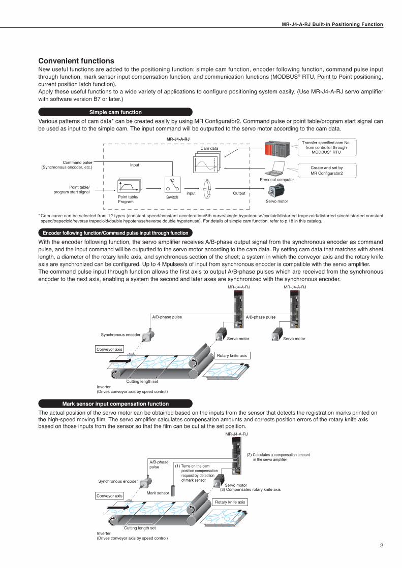
New useful functions are added to the positioning function: simple cam function, encoder following function, command pulse input through function, mark sensor input compensation function, and communication functions (MODBUS® RTU, Point to Point positioning, current position latch function).Apply these useful functions to a wide variety of applications to configure positioning system easily. (Use MR-J4-A-RJ servo amplifier with software version B7 or later.)
Mark sensor input compensation function
Encoder following function/Command pulse input through function
Simple cam function
Convenient functions
Various patterns of cam data* can be created easily by using MR Configurator2. Command pulse or point table/program start signal can be used as input to the simple cam. The input command will be outputted to the servo motor according to the cam data.
* Cam curve can be selected from 12 types (constant speed/constant acceleration/5th curve/single hypotenuse/cycloid/distorted trapezoid/distorted sine/distorted constant speed/trapecloid/reverse trapecloid/double hypotenuse/reverse double hypotenuse). For details of simple cam function, refer to p.18 in this catalog.
Input
SwitchOutputinput
MR-J4-A-RJ
Cam data
Point table/Program
Point table/program start signal
Command pulse(Synchronous encoder, etc.) Create and set by
MR Configurator2Personal computer
Servo motor
Transfer specified cam No. from controller through
MODBUS® RTU
With the encoder following function, the servo amplifier receives A/B-phase output signal from the synchronous encoder as command pulse, and the input command will be outputted to the servo motor according to the cam data. By setting cam data that matches with sheet length, a diameter of the rotary knife axis, and synchronous section of the sheet; a system in which the conveyor axis and the rotary knife axis are synchronized can be configured. Up to 4 Mpulses/s of input from synchronous encoder is compatible with the servo amplifier.The command pulse input through function allows the first axis to output A/B-phase pulses which are received from the synchronous encoder to the next axis, enabling a system the second and later axes are synchronized with the synchronous encoder.
Inverter(Drives conveyor axis by speed control)
Cutting length set
MR-J4-A-RJ MR-J4-A-RJ
Servo motorSynchronous encoder
A/B-phase pulse A/B-phase pulse
Rotary knife axisConveyor axis
Servo motor
The actual position of the servo motor can be obtained based on the inputs from the sensor that detects the registration marks printed on the high-speed moving film. The servo amplifier calculates compensation amounts and corrects position errors of the rotary knife axis based on those inputs from the sensor so that the film can be cut at the set position.
Conveyor axis Mark sensor
(1) Turns on the cam position compensation request by detection of mark sensor
(2) Calculates a compensation amount in the servo amplifier
(3) Compensates rotary knife axis
Inverter(Drives conveyor axis by speed control)
Cutting length set
Servo motorSynchronous encoder
A/B-phase pulse
Rotary knife axis
MR-J4-A-RJ
Built-in Positioning Function
MR-J4-A-RJ Built-in Positioning Function
3
MR-J4-A-RJ Built-in Positioning Function
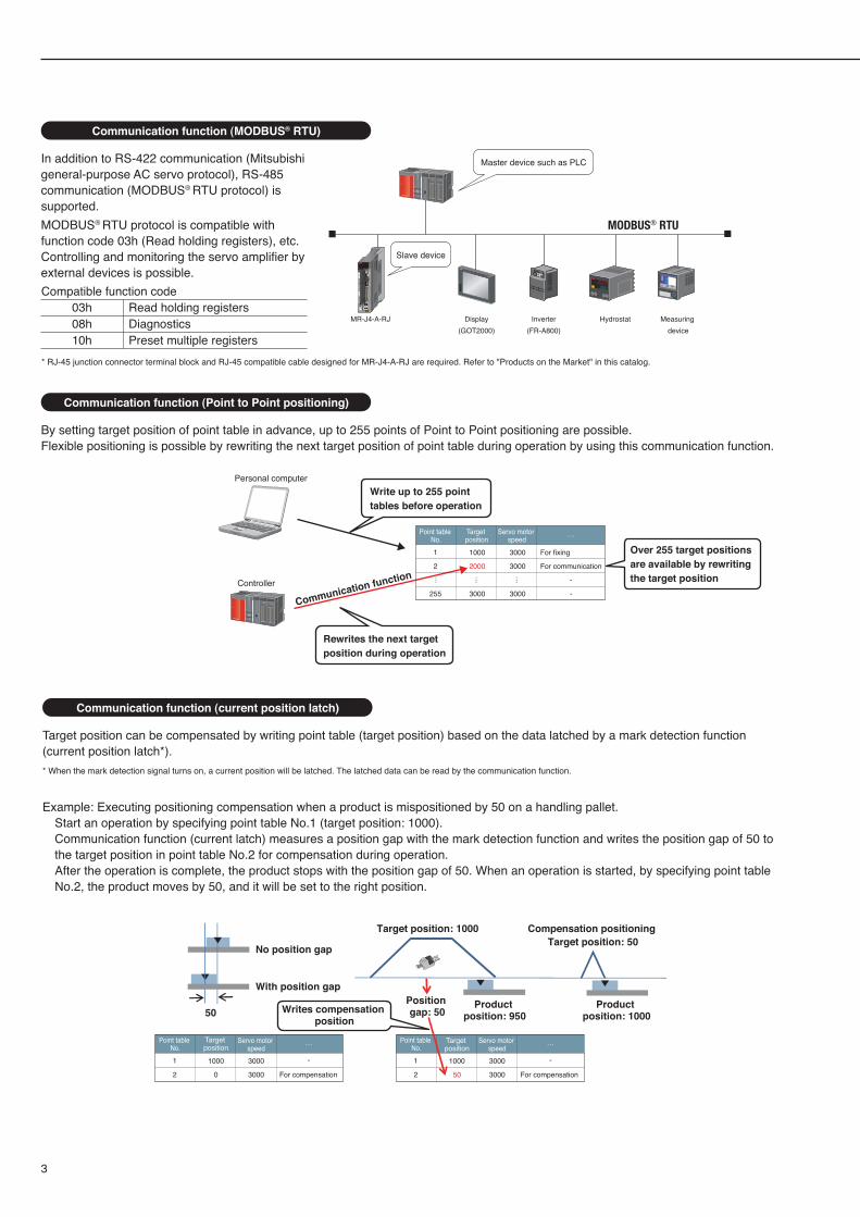
In addition to RS-422 communication (Mitsubishi general-purpose AC servo protocol), RS-485 communication (MODBUS® RTU protocol) is supported.MODBUS® RTU protocol is compatible with function code 03h (Read holding registers), etc. Controlling and monitoring the servo amplifier by external devices is possible.
Communication function (MODBUS® RTU)
By setting target position of point table in advance, up to 255 points of Point to Point positioning are possible.Flexible positioning is possible by rewriting the next target position of point table during operation by using this communication function.
Communication function (Point to Point positioning)
Write up to 255 point tables before operation
Rewrites the next target position during operation
MR‐J4‐A‐RJ
Personal computer
Controller
Communication function
* RJ-45 junction connector terminal block and RJ-45 compatible cable designed for MR-J4-A-RJ are required. Refer to "Products on the Market" in this catalog.
Master device such as PLC
Slave device
MODBUS® RTU
Inverter(FR-A800)
Display(GOT2000)
Hydrostat Measuring device
Compatible function code03h08h10h
Read holding registersDiagnosticsPreset multiple registers
Target position can be compensated by writing point table (target position) based on the data latched by a mark detection function (current position latch*).* When the mark detection signal turns on, a current position will be latched. The latched data can be read by the communication function.
Example: Executing positioning compensation when a product is mispositioned by 50 on a handling pallet.Start an operation by specifying point table No.1 (target position: 1000).Communication function (current latch) measures a position gap with the mark detection function and writes the position gap of 50 to the target position in point table No.2 for compensation during operation.After the operation is complete, the product stops with the position gap of 50. When an operation is started, by specifying point table No.2, the product moves by 50, and it will be set to the right position.
Communication function (current position latch)
No position gap
Target position: 1000 Compensation positioning Target position: 50
Product position: 1000
Product position: 950Writes compensation
position
With position gap
50Position gap: 50
Point table No.
Target position
Servo motor speed
…
1000 3000
2000 3000
For fixing
For communication
-
-3000 3000
1
2
… … …
255
Point table No.
Target position
Servo motor speed
…
1000 3000
0 3000 For compensation
- -1
2
Target position
Servo motor speed
…
1000 3000
50 3000 For compensation
1
2
Over 255 target positions are available by rewriting the target position
Point table No.
MR-J4-A-RJ Built-in Positioning Function
4
MR-J4-A-RJ Built-in Positioning Function
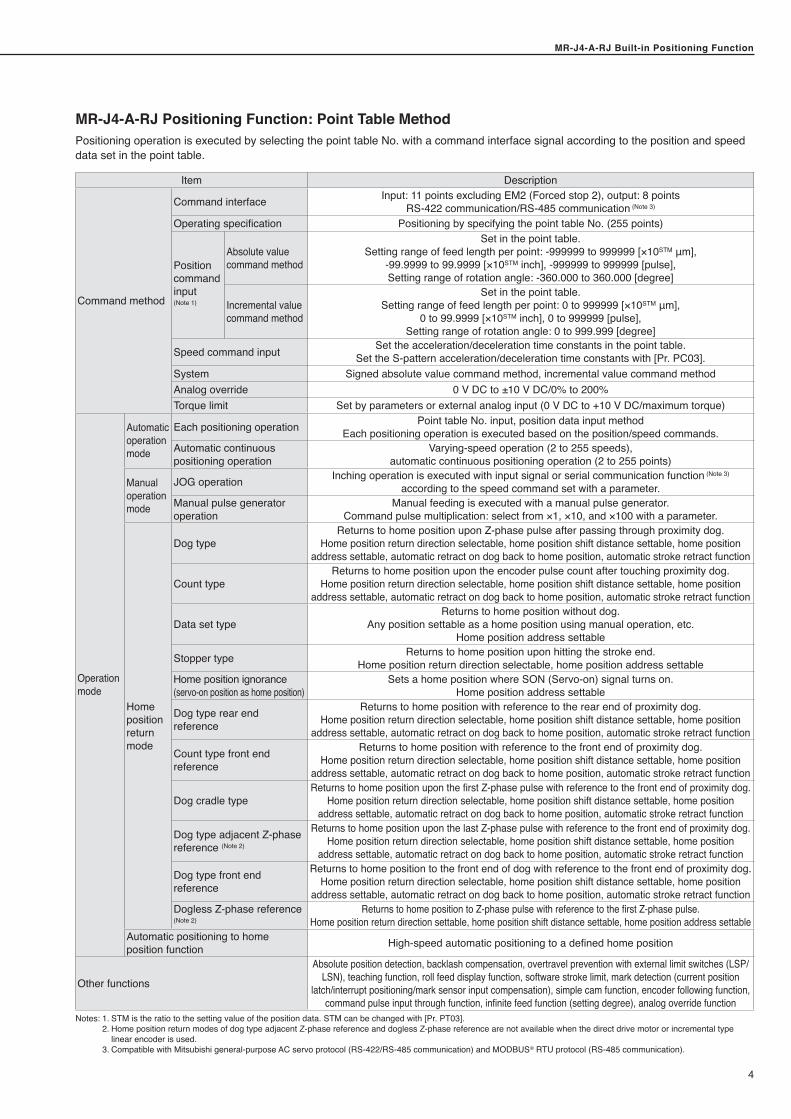
MR-J4-A-RJ Positioning Function: Point Table MethodPositioning operation is executed by selecting the point table No. with a command interface signal according to the position and speed data set in the point table.
Item Description
Command method
Command interface Input: 11 points excluding EM2 (Forced stop 2), output: 8 points RS-422 communication/RS-485 communication (Note 3)
Operating specification Positioning by specifying the point table No. (255 points)
Position command input(Note 1)
Absolute value command method
Set in the point table.Setting range of feed length per point: -999999 to 999999 [×10STM μm],
-99.9999 to 99.9999 [×10STM inch], -999999 to 999999 [pulse], Setting range of rotation angle: -360.000 to 360.000 [degree]
Incremental value command method
Set in the point table.Setting range of feed length per point: 0 to 999999 [×10STM μm],
0 to 99.9999 [×10STM inch], 0 to 999999 [pulse], Setting range of rotation angle: 0 to 999.999 [degree]
Speed command input Set the acceleration/deceleration time constants in the point table.Set the S-pattern acceleration/deceleration time constants with [Pr. PC03].
System Signed absolute value command method, incremental value command methodAnalog override 0 V DC to ±10 V DC/0% to 200%Torque limit Set by parameters or external analog input (0 V DC to +10 V DC/maximum torque)
Operationmode
Automaticoperationmode
Each positioning operation Point table No. input, position data input method Each positioning operation is executed based on the position/speed commands.
Automatic continuous positioning operation
Varying-speed operation (2 to 255 speeds), automatic continuous positioning operation (2 to 255 points)
Manualoperationmode
JOG operation Inching operation is executed with input signal or serial communication function (Note 3) according to the speed command set with a parameter.
Manual pulse generator operation
Manual feeding is executed with a manual pulse generator.Command pulse multiplication: select from ×1, ×10, and ×100 with a parameter.
Homepositionreturn mode
Dog typeReturns to home position upon Z-phase pulse after passing through proximity dog.
Home position return direction selectable, home position shift distance settable, home position address settable, automatic retract on dog back to home position, automatic stroke retract function
Count typeReturns to home position upon the encoder pulse count after touching proximity dog.
Home position return direction selectable, home position shift distance settable, home position address settable, automatic retract on dog back to home position, automatic stroke retract function
Data set typeReturns to home position without dog.
Any position settable as a home position using manual operation, etc.Home position address settable
Stopper type Returns to home position upon hitting the stroke end.Home position return direction selectable, home position address settable
Home position ignorance (servo-on position as home position)
Sets a home position where SON (Servo-on) signal turns on.Home position address settable
Dog type rear end reference
Returns to home position with reference to the rear end of proximity dog.Home position return direction selectable, home position shift distance settable, home position
address settable, automatic retract on dog back to home position, automatic stroke retract function
Count type front end reference
Returns to home position with reference to the front end of proximity dog.Home position return direction selectable, home position shift distance settable, home position
address settable, automatic retract on dog back to home position, automatic stroke retract function
Dog cradle typeReturns to home position upon the first Z-phase pulse with reference to the front end of proximity dog.
Home position return direction selectable, home position shift distance settable, home position address settable, automatic retract on dog back to home position, automatic stroke retract function
Dog type adjacent Z-phase reference (Note 2)
Returns to home position upon the last Z-phase pulse with reference to the front end of proximity dog.Home position return direction selectable, home position shift distance settable, home position
address settable, automatic retract on dog back to home position, automatic stroke retract function
Dog type front end reference
Returns to home position to the front end of dog with reference to the front end of proximity dog.Home position return direction selectable, home position shift distance settable, home position
address settable, automatic retract on dog back to home position, automatic stroke retract functionDogless Z-phase reference(Note 2)
Returns to home position to Z-phase pulse with reference to the first Z-phase pulse.Home position return direction settable, home position shift distance settable, home position address settable
Automatic positioning to home position function High-speed automatic positioning to a defined home position
Other functions
Absolute position detection, backlash compensation, overtravel prevention with external limit switches (LSP/LSN), teaching function, roll feed display function, software stroke limit, mark detection (current position
latch/interrupt positioning/mark sensor input compensation), simple cam function, encoder following function, command pulse input through function, infinite feed function (setting degree), analog override function
Notes: 1. STM is the ratio to the setting value of the position data. STM can be changed with [Pr. PT03]. 2. Home position return modes of dog type adjacent Z-phase reference and dogless Z-phase reference are not available when the direct drive motor or incremental type
linear encoder is used. 3. Compatible with Mitsubishi general-purpose AC servo protocol (RS-422/RS-485 communication) and MODBUS® RTU protocol (RS-485 communication).
MR-J4-A-RJ Built-in Positioning Function
5
MR-J4-A-RJ Built-in Positioning Function
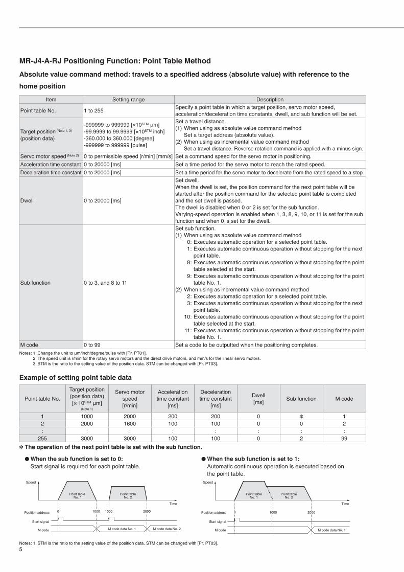
MR-J4-A-RJ Positioning Function: Point Table MethodAbsolute value command method: travels to a specified address (absolute value) with reference to the home position
Item Setting range Description
Point table No. 1 to 255 Specify a point table in which a target position, servo motor speed, acceleration/deceleration time constants, dwell, and sub function will be set.
Target position (Note 1, 3)
(position data)
-999999 to 999999 [×10STM μm]-99.9999 to 99.9999 [×10STM inch]-360.000 to 360.000 [degree]-999999 to 999999 [pulse]
Set a travel distance.(1) When using as absolute value command method Set a target address (absolute value).(2) When using as incremental value command method Set a travel distance. Reverse rotation command is applied with a minus sign.
Servo motor speed (Note 2) 0 to permissible speed [r/min] [mm/s] Set a command speed for the servo motor in positioning.Acceleration time constant 0 to 20000 [ms] Set a time period for the servo motor to reach the rated speed.Deceleration time constant 0 to 20000 [ms] Set a time period for the servo motor to decelerate from the rated speed to a stop.
Dwell 0 to 20000 [ms]
Set dwell.When the dwell is set, the position command for the next point table will be started after the position command for the selected point table is completed and the set dwell is passed.The dwell is disabled when 0 or 2 is set for the sub function.Varying-speed operation is enabled when 1, 3, 8, 9, 10, or 11 is set for the sub function and when 0 is set for the dwell.
Sub function 0 to 3, and 8 to 11
Set sub function.(1) When using as absolute value command method 0: Executes automatic operation for a selected point table. 1: Executes automatic continuous operation without stopping for the next
point table. 8: Executes automatic continuous operation without stopping for the point
table selected at the start. 9: Executes automatic continuous operation without stopping for the point
table No. 1.(2) When using as incremental value command method 2: Executes automatic operation for a selected point table. 3: Executes automatic continuous operation without stopping for the next
point table. 10: Executes automatic continuous operation without stopping for the point
table selected at the start. 11: Executes automatic continuous operation without stopping for the point
table No. 1.M code 0 to 99 Set a code to be outputted when the positioning completes.Notes: 1. Change the unit to μm/inch/degree/pulse with [Pr. PT01]. 2. The speed unit is r/min for the rotary servo motors and the direct drive motors, and mm/s for the linear servo motors. 3. STM is the ratio to the setting value of the position data. STM can be changed with [Pr. PT03].
Example of setting point table data
Point table No.Target position(position data)[× 10STM μm]
(Note 1)
Servo motorspeed[r/min]
Acceleration time constant
[ms]
Deceleration time constant
[ms]
Dwell[ms] Sub function M code
1 1000 2000 200 200 0 ✽ 12 2000 1600 100 100 0 0 2: : : : : : : :
255 3000 3000 100 100 0 2 99✽ The operation of the next point table is set with the sub function.
Speed
Position address
Start signal
M code
Point tableNo. 1
Point tableNo. 2
M code data No. 1
0 1000 2000
Time
When the sub function is set to 1: ●
Automatic continuous operation is executed based on the point table.
When the sub function is set to 0: ●
Start signal is required for each point table.
Notes: 1. STM is the ratio to the setting value of the position data. STM can be changed with [Pr. PT03].
Position address
Start signal
M code
Speed
Point table No. 1
Point tableNo. 2
10000 1000 2000
M code data No. 1 M code data No. 2
Time
MR-J4-A-RJ Built-in Positioning FunctionMR-J4-A-RJ Built-in Positioning Function
6
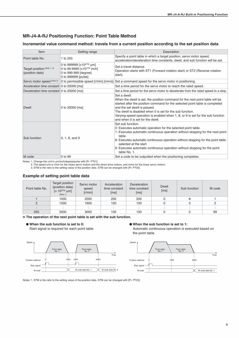
MR-J4-A-RJ Positioning Function: Point Table MethodIncremental value command method: travels from a current position according to the set position data
Item Setting range Description
Point table No. 1 to 255 Specify a point table in which a target position, servo motor speed, acceleration/deceleration time constants, dwell, and sub function will be set.
Target position (Note 1, 3)
(position data)
0 to 999999 [×10STM μm]0 to 99.9999 [×10STM inch]0 to 999.999 [degree]0 to 999999 [pulse]
Set a travel distance.Operation starts with ST1 (Forward rotation start) or ST2 (Reverse rotation start).
Servo motor speed (Note 2) 0 to permissible speed [r/min] [mm/s] Set a command speed for the servo motor in positioning.Acceleration time constant 0 to 20000 [ms] Set a time period for the servo motor to reach the rated speed.Deceleration time constant 0 to 20000 [ms] Set a time period for the servo motor to decelerate from the rated speed to a stop.
Dwell 0 to 20000 [ms]
Set a dwell.When the dwell is set, the position command for the next point table will be started after the position command for the selected point table is completed and the set dwell is passed.The dwell is disabled when 0 is set for the sub function.Varying-speed operation is enabled when 1, 8, or 9 is set for the sub function and when 0 is set for the dwell.
Sub function 0, 1, 8, and 9
Set sub function.0: Executes automatic operation for the selected point table.1: Executes automatic continuous operation without stopping for the next point
table.8: Executes automatic continuous operation without stopping for the point table
selected at the start.9: Executes automatic continuous operation without stopping for the point
table No. 1.M code 0 to 99 Set a code to be outputted when the positioning completes.Notes: 1. Change the unit to μm/inch/degree/pulse with [Pr. PT01]. 2. The speed unit is r/min for the rotary servo motors and the direct drive motors, and mm/s for the linear servo motors. 3. STM is the ratio to the setting value of the position data. STM can be changed with [Pr. PT03].
Example of setting point table data
Point table No.Target position(position data)[× 10STM μm]
(Note 1)
Servo motorspeed[r/min]
Acceleration time constant
[ms]
Deceleration time constant
[ms]
Dwell[ms] Sub function M code
1 1000 2000 200 200 0 ✽ 12 1000 1600 100 100 0 0 2: : : : : : : :
255 3000 3000 100 100 0 0 99✽ The operation of the next point table is set with the sub function.
Speed
Position address
Start signal
M code
Point table No. 1
Point table No. 2
M code data No. 1
0 1000 2000
Time
When the sub function is set to 1: ●
Automatic continuous operation is executed based on the point table.
When the sub function is set to 0: ●
Start signal is required for each point table.
Notes: 1. STM is the ratio to the setting value of the position data. STM can be changed with [Pr. PT03].
Position address
Start signal
M code
Speed
Point table No. 1
Point table No. 2
10000 1000 2000
M code data No. 1 M code data No. 2
Time
MR-J4-A-RJ Built-in Positioning Function
7
MR-J4-A-RJ Built-in Positioning Function
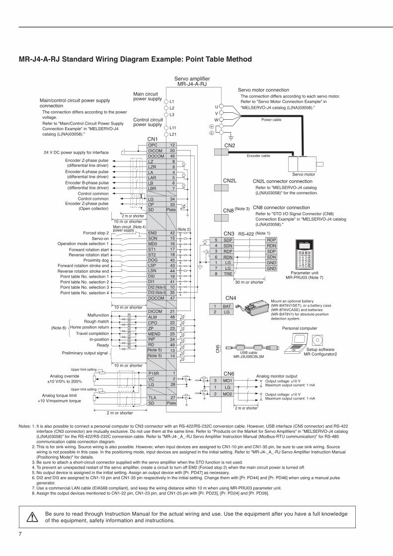
MR-J4-A-RJ Standard Wiring Diagram Example: Point Table Method
CN
5CN8
CN2L
CN2
L1L2L3
L11L21
P15R 1VC 2
27
LG
TLA
28
SD
EM2 42
DI3 (Note 6) 35DI2 (Note 6) 10
SON 15MD0 16
18ST1ST2DOGLSP
17
4543
LSN 44DI0 19DI1 41
DOCOM 47
DICOM 21ALM 48
ZP 23MEND 25
CPO 22
24INP49RD1314
DICOMDOCOM
20OPC 12
4689456
LZ
7
LZRLA
34
LAR
33
LBLBR
LGOPSD
CN6
CN3SDPSDNRDPRDNLGLG
TRE
5436178
RDPRDNSDPSDNGNDGND
RS-422
MO13LG1
MO22
RA1
RA2
RA3
RA4
RA5
RA6
CN1
UVW
CN4BATLG
12
Mount an optional battery (MR-BAT6V1SET), or a battery case (MR-BT6VCASE) and batteries (MR-BAT6V1) for absolute position detection system.
Encoder Z-phase pulse(differential line driver)
Encoder Z-phase pulse(Open collector)
Encoder A-phase pulse(differential line driver)
Encoder B-phase pulse(differential line driver)
Control commonControl common
24 V DC power supply for interface
2 m or shorter10 m or shorterMain circuit power supply
(Note 4) (Note 2)Forced stop 2
Servo-onOperation mode selection 1
Forward rotation startReverse rotation start
Proximity dogForward rotation stroke endReverse rotation stroke end
Point table No. selection 1Point table No. selection 2Point table No. selection 3Point table No. selection 4
10 m or shorter
30 m or shorter
10 m or shorter
2 m or shorter
MalfunctionRough match
Travel completionHome position return
In-positionReady
Preliminary output signal
Analog torque limit+10 V/maximum torque
Upper limit setting
Upper limit setting
Plate
(Note 5)(Note 5)
(Note 8)
(Note 1)
(Note 3)Plate
Main circuit power supply
Control circuit power supply
Servo amplifierMR-J4-A-RJ
Servo motor connection The connection differs according to each servo motor.Refer to "Servo Motor Connection Example" in "MELSERVO-J4 catalog (L(NA)03058)."
Encoder cable
Power cable
Servo motor
CN8 connector connectionRefer to "STO I/O Signal Connector (CN8) Connection Example" in "MELSERVO-J4 catalog (L(NA)03058)."
CN2L connector connectionRefer to "MELSERVO-J4 catalog (L(NA)03058)" for the connection.
Setup softwareMR Configurator2
Parameter unitMR-PRU03 (Note 7)
Personal computer
USB cableMR-J3USBCBL3M
Analog monitor outputOutput voltage: ±10 VMaximum output current: 1 mA
Output voltage: ±10 VMaximum output current: 1 mA
2 m or shorter
Main/control circuit power supply connection
The connection differs according to the power voltage.Refer to "Main/Control Circuit Power Supply Connection Example" in "MELSERVO-J4 catalog (L(NA)03058)."
Analog override±10 V/0% to 200%
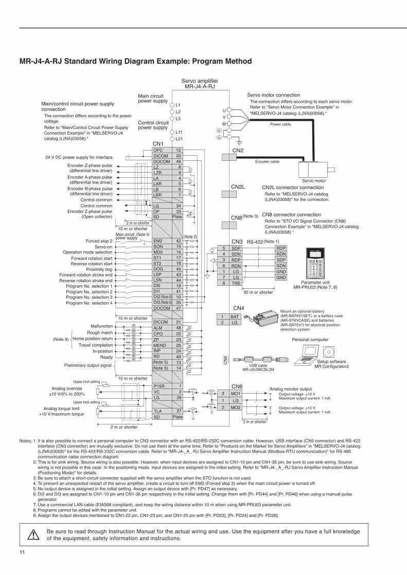
Notes: 1. It is also possible to connect a personal computer to CN3 connector with an RS-422/RS-232C conversion cable. However, USB interface (CN5 connector) and RS-422 interface (CN3 connector) are mutually exclusive. Do not use them at the same time. Refer to "Products on the Market for Servo Amplifiers" in "MELSERVO-J4 catalog (L(NA)03058)" for the RS-422/RS-232C conversion cable. Refer to "MR-J4-_A_-RJ Servo Amplifier Instruction Manual (Modbus-RTU communication)" for RS-485 communication cable connection diagram.
2. This is for sink wiring. Source wiring is also possible. However, when input devices are assigned to CN1-10 pin and CN1-35 pin, be sure to use sink wiring. Source wiring is not possible in this case. In the positioning mode, input devices are assigned in the initial setting. Refer to "MR-J4-_A_-RJ Servo Amplifier Instruction Manual (Positioning Mode)" for details.
3. Be sure to attach a short-circuit connector supplied with the servo amplifier when the STO function is not used. 4. To prevent an unexpected restart of the servo amplifier, create a circuit to turn off EM2 (Forced stop 2) when the main circuit power is turned off. 5. No output device is assigned in the initial setting. Assign an output device with [Pr. PD47] as necessary. 6. DI2 and DI3 are assigned to CN1-10 pin and CN1-35 pin respectively in the initial setting. Change them with [Pr. PD44] and [Pr. PD46] when using a manual pulse
generator. 7. Use a commercial LAN cable (EIA568 compliant), and keep the wiring distance within 10 m when using MR-PRU03 parameter unit. 8. Assign the output devices mentioned to CN1-22 pin, CN1-23 pin, and CN1-25 pin with [Pr. PD23], [Pr. PD24] and [Pr. PD26].
Be sure to read through Instruction Manual for the actual wiring and use. Use the equipment after you have a full knowledge of the equipment, safety information and instructions.
MR-J4-A-RJ Built-in Positioning FunctionMR-J4-A-RJ Built-in Positioning Function
8
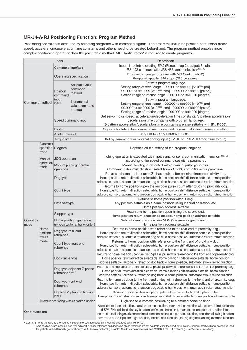
MR-J4-A-RJ Positioning Function: Program MethodPositioning operation is executed by selecting programs with command signals. The programs including position data, servo motor speed, acceleration/deceleration time constants and others need to be created beforehand. The program method enables more complex positioning operation than the point table method. MR Configurator2 is required to create programs.
Item Description
Command method
Command interface Input: 11 points excluding EM2 (Forced stop 2), output: 8 points RS-422 communication/RS-485 communication (Note 3)
Operating specification Program language (program with MR Configurator2)Program capacity: 640 steps (256 programs)
Positioncommandinput(Note 1)
Absolute value command method
Set with program language.Setting range of feed length: -999999 to 999999 [×10STM μm], -99.9999 to 99.9999 [×10STM inch], -999999 to 999999 [pulse], Setting range of rotation angle: -360.000 to 360.000 [degree]
Incremental value command method
Set with program language.Setting range of feed length: -999999 to 999999 [×10STM μm], -99.9999 to 99.9999 [×10STM inch], -999999 to 999999 [pulse], Setting range of rotation angle: -999.999 to 999.999 [degree]
Speed command inputSet servo motor speed, acceleration/deceleration time constants, S-pattern acceleration/
deceleration time constants with program language.S-pattern acceleration/deceleration time constants are also settable with [Pr. PC03].
System Signed absolute value command method/signed incremental value command methodAnalog override 0 V DC to ±10 V DC/0% to 200%Torque limit Set by parameters or external analog input (0 V DC to +10 V DC/maximum torque)
Operationmode
Automatic operation mode
Program Depends on the setting of the program language
Manual operation mode
JOG operation Inching operation is executed with input signal or serial communication function (Note 3) according to the speed command set with a parameter.
Manual pulse generator operation
Manual feeding is executed with a manual pulse generator.Command pulse multiplication: select from ×1, ×10, and ×100 with a parameter.
Homepositionreturn mode
Dog typeReturns to home position upon Z-phase pulse after passing through proximity dog.
Home position return direction selectable, home position shift distance settable, home position address settable, automatic retract on dog back to home position, automatic stroke retract function
Count typeReturns to home position upon the encoder pulse count after touching proximity dog.
Home position return direction selectable, home position shift distance settable, home position address settable, automatic retract on dog back to home position, automatic stroke retract function
Data set typeReturns to home position without dog.
Any position settable as a home position using manual operation, etc. Home position address settable
Stopper type Returns to home position upon hitting the stroke end.Home position return direction selectable, home position address settable
Home position ignorance (servo-on position as home position)
Sets a home position where SON (Servo-on) signal turns on.Home position address settable
Dog type rear end reference
Returns to home position with reference to the rear end of proximity dog.Home position return direction selectable, home position shift distance settable, home position
address settable, automatic retract on dog back to home position, automatic stroke retract function
Count type front end reference
Returns to home position with reference to the front end of proximity dog.Home position return direction selectable, home position shift distance settable, home position
address settable, automatic retract on dog back to home position, automatic stroke retract function
Dog cradle typeReturns to home position upon the first Z-phase pulse with reference to the front end of proximity dog.
Home position return direction selectable, home position shift distance settable, home position address settable, automatic retract on dog back to home position, automatic stroke retract function
Dog type adjacent Z-phase reference (Note 2)
Returns to home position upon the last Z-phase pulse with reference to the front end of proximity dog.Home position return direction selectable, home position shift distance settable, home position
address settable, automatic retract on dog back to home position, automatic stroke retract function
Dog type front end reference
Returns to home position to the front end of dog with reference to the front end of proximity dog.Home position return direction selectable, home position shift distance settable, home position
address settable, automatic retract on dog back to home position, automatic stroke retract functionDogless Z-phase reference(Note 2)
Returns to home position to Z-phase pulse with reference to the first Z-phase pulse.Home position return direction settable, home position shift distance settable, home position address settable
Automatic positioning to home position function High-speed automatic positioning to a defined home position
Other functions
Absolute position detection, backlash compensation, overtravel prevention with external limit switches (LSP/LSN), roll feed display function, software stroke limit, mark detection (current position latch/
interrupt positioning/mark sensor input compensation), simple cam function, encoder following function, command pulse input through function, infinite feed function (setting degree), analog override function
Notes: 1. STM is the ratio to the setting value of the position data. STM can be changed with [Pr. PT03]. 2. Home position return modes of dog type adjacent Z-phase reference and dogless Z-phase reference are not available when the direct drive motor or incremental type linear encoder is used. 3. Compatible with Mitsubishi general-purpose AC servo protocol (RS-422/RS-485 communication) and MODBUS® RTU protocol (RS-485 communication).
MR-J4-A-RJ Built-in Positioning Function
9
MR-J4-A-RJ Built-in Positioning Function
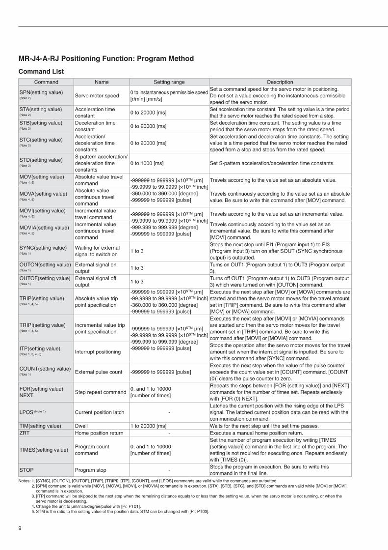
MR-J4-A-RJ Positioning Function: Program MethodCommand List
Command Name Setting range Description
SPN(setting value)
(Note 2) Servo motor speed 0 to instantaneous permissible speed[r/min] [mm/s]
Set a command speed for the servo motor in positioning. Do not set a value exceeding the instantaneous permissible speed of the servo motor.
STA(setting value)
(Note 2)Acceleration time constant 0 to 20000 [ms] Set acceleration time constant. The setting value is a time period
that the servo motor reaches the rated speed from a stop.STB(setting value)
(Note 2)Deceleration time constant 0 to 20000 [ms] Set deceleration time constant. The setting value is a time
period that the servo motor stops from the rated speed.
STC(setting value)
(Note 2)
Acceleration/deceleration time constants
0 to 20000 [ms]Set acceleration and deceleration time constants. The setting value is a time period that the servo motor reaches the rated speed from a stop and stops from the rated speed.
STD(setting value)
(Note 2)
S-pattern acceleration/deceleration time constants
0 to 1000 [ms] Set S-pattern acceleration/deceleration time constants.
MOV(setting value)
(Note 4, 5)Absolute value travel command -999999 to 999999 [×10STM μm]
-99.9999 to 99.9999 [×10STM inch]-360.000 to 360.000 [degree]-999999 to 999999 [pulse]
Travels according to the value set as an absolute value.
MOVA(setting value)
(Note 4, 5)
Absolute value continuous travel command
Travels continuously according to the value set as an absolute value. Be sure to write this command after [MOV] command.
MOVI(setting value)
(Note 4, 5)Incremental value travel command -999999 to 999999 [×10STM μm]
-99.9999 to 99.9999 [×10STM inch]-999.999 to 999.999 [degree]-999999 to 999999 [pulse]
Travels according to the value set as an incremental value.
MOVIA(setting value)
(Note 4, 5)
Incremental value continuous travel command
Travels continuously according to the value set as an incremental value. Be sure to write this command after [MOVI] command.
SYNC(setting value) (Note 1)
Waiting for external signal to switch on 1 to 3
Stops the next step until PI1 (Program input 1) to PI3 (Program input 3) turn on after SOUT (SYNC synchronous output) is outputted.
OUTON(setting value)
(Note 1)External signal on output 1 to 3 Turns on OUT1 (Program output 1) to OUT3 (Program output
3).OUTOF(setting value)
(Note 1)External signal off output 1 to 3 Turns off OUT1 (Program output 1) to OUT3 (Program output
3) which were turned on with [OUTON] command.
TRIP(setting value)
(Note 1, 4, 5)Absolute value trip point specification
-999999 to 999999 [×10STM μm]-99.9999 to 99.9999 [×10STM inch]-360.000 to 360.000 [degree]-999999 to 999999 [pulse]
Executes the next step after [MOV] or [MOVA] commands are started and then the servo motor moves for the travel amount set in [TRIP] command. Be sure to write this command after [MOV] or [MOVA] command.
TRIPI(setting value)
(Note 1, 4, 5)Incremental value trip point specification -999999 to 999999 [×10STM μm]
-99.9999 to 99.9999 [×10STM inch]-999.999 to 999.999 [degree]-999999 to 999999 [pulse]
Executes the next step after [MOVI] or [MOVIA] commands are started and then the servo motor moves for the travel amount set in [TRIPI] command. Be sure to write this command after [MOVI] or [MOVIA] command.
ITP(setting value)
(Note 1, 3, 4, 5) Interrupt positioningStops the operation after the servo motor moves for the travel amount set when the interrupt signal is inputted. Be sure to write this command after [SYNC] command.
COUNT(setting value)
(Note 1) External pulse count -999999 to 999999 [pulse]Executes the next step when the value of the pulse counter exceeds the count value set in [COUNT] command. [COUNT (0)] clears the pulse counter to zero.
FOR(setting value) NEXT Step repeat command 0, and 1 to 10000
[number of times]
Repeats the steps between [FOR (setting value)] and [NEXT] commands for the number of times set. Repeats endlessly with [FOR (0) NEXT].
LPOS (Note 1) Current position latch -Latches the current position with the rising edge of the LPS signal. The latched current position data can be read with the communication command.
TIM(setting value) Dwell 1 to 20000 [ms] Waits for the next step until the set time passes.ZRT Home position return - Executes a manual home position return.
TIMES(setting value) Program count command
0, and 1 to 10000 [number of times]
Set the number of program execution by writing [TIMES (setting value)] command in the first line of the program. The setting is not required for executing once. Repeats endlessly with [TIMES (0)].
STOP Program stop - Stops the program in execution. Be sure to write thiscommand in the final line.
Notes: 1. [SYNC], [OUTON], [OUTOF], [TRIP], [TRIPI], [ITP], [COUNT], and [LPOS] commands are valid while the commands are outputted. 2. [SPN] command is valid while [MOV], [MOVA], [MOVI], or [MOVIA] command is in execution. [STA], [STB], [STC], and [STD] commands are valid while [MOV] or [MOVI]
command is in execution. 3. [ITP] command will be skipped to the next step when the remaining distance equals to or less than the setting value, when the servo motor is not running, or when the
servo motor is decelerating. 4. Change the unit to μm/inch/degree/pulse with [Pr. PT01]. 5. STM is the ratio to the setting value of the position data. STM can be changed with [Pr. PT03].
MR-J4-A-RJ Built-in Positioning FunctionMR-J4-A-RJ Built-in Positioning Function
10
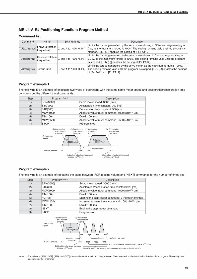
MR-J4-A-RJ Positioning Function: Program Method
Notes: 1. The values in [SPN], [STA], [STB], and [STC] commands remains valid until they are reset. The values will not be initialized at the start of the program. The settings are also valid in other programs.
Position address
Servo motorspeed
0 1000 1000 2500
(4) Absolute value travel command (1000 × 10STM [µm])
(5) Dwell (100 [ms])
(1) Speed (3000 [r/min])
(1) Speed (3000 [r/min])
(2) Acceleration time constant (200 [ms])
(3) Deceleration time constant (300 [ms])
(2) Acceleration time constant (200 [ms])
(3) Deceleration time constant (300 [ms])
(6) Absolute value travel command (2500 × 10STM [µm])
Program example 1The following is an example of executing two types of operations with the same servo motor speed and acceleration/deceleration time constants but the different travel commands.
Step Program (Note 1) Description(1) SPN(3000) Servo motor speed: 3000 [r/min](2) STA(200) Acceleration time constant: 200 [ms](3) STB(300) Deceleration time constant: 300 [ms](4) MOV(1000) Absolute value travel command: 1000 [×10STM μm](5) TIM(100) Dwell: 100 [ms](6) MOV(2500) Absolute value travel command: 2500 [×10STM μm](7) STOP Program stop
Command listCommand Name Setting range Description
TLP(setting value) Forward rotation torque limit 0, and 1 to 1000 [0.1%]
Limits the torque generated by the servo motor driving in CCW and regenerating in CW, as the maximum torque is 100%. The setting remains valid until the program is stopped. [TLP (0)] enables the setting of [Pr. PA11].
TLN(setting value) Reverse rotation torque limit 0, and 1 to 1000 [0.1%]
Limits the torque generated by the servo motor driving in CW and regenerating in CCW, as the maximum torque is 100%. The setting remains valid until the program is stopped. [TLN (0)] enables the setting of [Pr. PA12].
TQL(setting value) Torque limit 0, and 1 to 1000 [0.1%]Limits the torque generated by the servo motor, as the maximum torque is 100%. The setting remains valid until the program is stopped. [TQL (0)] enables the settings of [Pr. PA11] and [Pr. PA12].
Program example 2The following is an example of repeating the steps between [FOR (setting value)] and [NEXT] commands for the number of times set.
Step Program (Note 1) Description(1) SPN(3000) Servo motor speed: 3000 [r/min](2) STC(20) Acceleration/deceleration time constants: 20 [ms](3) MOV(1000) Absolute value travel command: 1000 [×10STM μm](4) TIM(100) Dwell: 100 [ms](5) FOR(3) Starting the step repeat command: 3 [number of times](6) MOVI(100) Incremental value travel command: 100 [×10STM μm](7) TIM(100) Dwell: 100 [ms](8) NEXT Ending the step repeat command(9) STOP Program stop
(4) Dwell(100 [ms])
(7) Dwell (100 [ms])
(2) Acceleration time constant (20 [ms])
(2) Deceleration time constant (20 [ms])
0 1000 1100 13001200
Steps (6) and (7) are repeated for the number of times specified by step (5).
Position address
Servo motorspeed
(1) Speed (3000 [r/min])
(6) Incremental value travel command(100 × 10STM [µm])(3) Absolute value travel command (1000 × 10STM [µm])
MR-J4-A-RJ Built-in Positioning Function
11
MR-J4-A-RJ Built-in Positioning Function
MR-J4-A-RJ Standard Wiring Diagram Example: Program Method
Control circuit power supply
USB cableMR-J3USBCBL3M
CN
5CN8
CN2L
CN2
L1L2L3
L11L21
P15R 1VC 2
27
LG
TLA
28
SD
EM2 42
3510
SON 15MD0 16
18ST1ST2DOGLSP
17
4543
LSN 44DI0 19DI1 41
DOCOM 47
DICOM 21ALM 48
ZP 23MEND 25
CPO 22
24INP49RD1314
DICOMDOCOM
204689456
LZ
7
LZRLA
34
LAR
33
LBLBR
LGOPSD
CN6
CN3SDPSDNRDPRDNLGLG
TRE
5436178
RDPRDNSDPSDNGNDGND
RS-422
MO13LG1
MO22
RA1
RA2
RA3
RA4
RA5
RA6
CN1
UVW
Main/control circuit power supply connection
The connection differs according to the power voltage.Refer to "Main/Control Circuit Power Supply Connection Example" in "MELSERVO-J4 catalog (L(NA)03058)."
Encoder Z-phase pulse(differential line driver)
Encoder Z-phase pulse(Open collector)
Encoder A-phase pulse(differential line driver)
Encoder B-phase pulse(differential line driver)
Control commonControl common
24 V DC power supply for interface
Main circuit power supply
2 m or shorter10 m or shorter
10 m or shorter
10 m or shorter
Main circuit power supply
(Note 4)Forced stop 2
Servo-onOperation mode selection
Forward rotation startReverse rotation start
Proximity dogForward rotation stroke endReverse rotation stroke end
Program No. selection 1Program No. selection 2Program No. selection 3Program No. selection 4
MalfunctionRough match
Travel completionHome position return
In-positionReady
Preliminary output signal
(Note 9)
Analog torque limit+10 V/maximum torque
Upper limit setting
Upper limit setting
Analog override±10 V/0% to 200%
2 m or shorter
Plate
(Note 5)(Note 5)
DI3 (Note 6)DI2 (Note 6)
(Note 2)
Plate
Setup softwareMR Configurator2
Personal computer
Analog monitor outputOutput voltage: ±10 VMaximum output current: 1 mA
Output voltage: ±10 VMaximum output current: 1 mA
2 m or shorter
30 m or shorter
(Note 1)
(Note 3) CN8 connector connectionRefer to "STO I/O Signal Connector (CN8) Connection Example" in "MELSERVO-J4 catalog (L(NA)03058)."
CN2L connector connectionRefer to "MELSERVO-J4 catalog (L(NA)03058)" for the connection.
Encoder cable
Power cable
Servo motor
Servo motor connection The connection differs according to each servo motor.Refer to "Servo Motor Connection Example" in "MELSERVO-J4 catalog (L(NA)03058)."
Servo amplifierMR-J4-A-RJ
Parameter unitMR-PRU03 (Note 7, 8)
CN4BATLG
12
Mount an optional battery (MR-BAT6V1SET), or a battery case (MR-BT6VCASE) and batteries (MR-BAT6V1) for absolute position detection system.
OPC 12
Notes: 1. It is also possible to connect a personal computer to CN3 connector with an RS-422/RS-232C conversion cable. However, USB interface (CN5 connector) and RS-422 interface (CN3 connector) are mutually exclusive. Do not use them at the same time. Refer to "Products on the Market for Servo Amplifiers" in "MELSERVO-J4 catalog (L(NA)03058)" for the RS-422/RS-232C conversion cable. Refer to "MR-J4-_A_-RJ Servo Amplifier Instruction Manual (Modbus-RTU communication)" for RS-485 communication cable connection diagram.
2. This is for sink wiring. Source wiring is also possible. However, when input devices are assigned to CN1-10 pin and CN1-35 pin, be sure to use sink wiring. Source wiring is not possible in this case. In the positioning mode, input devices are assigned in the initial setting. Refer to "MR-J4-_A_-RJ Servo Amplifier Instruction Manual (Positioning Mode)" for details.
3. Be sure to attach a short-circuit connector supplied with the servo amplifier when the STO function is not used. 4. To prevent an unexpected restart of the servo amplifier, create a circuit to turn off EM2 (Forced stop 2) when the main circuit power is turned off. 5. No output device is assigned in the initial setting. Assign an output device with [Pr. PD47] as necessary. 6. DI2 and DI3 are assigned to CN1-10 pin and CN1-35 pin respectively in the initial setting. Change them with [Pr. PD44] and [Pr. PD46] when using a manual pulse
generator. 7. Use a commercial LAN cable (EIA568 compliant), and keep the wiring distance within 10 m when using MR-PRU03 parameter unit. 8. Programs cannot be edited with the parameter unit. 9. Assign the output devices mentioned to CN1-22 pin, CN1-23 pin, and CN1-25 pin with [Pr. PD23], [Pr. PD24] and [Pr. PD26].
Be sure to read through Instruction Manual for the actual wiring and use. Use the equipment after you have a full knowledge of the equipment, safety information and instructions.
MR-J4-A-RJ Built-in Positioning FunctionMR-J4-A-RJ Built-in Positioning Function
12
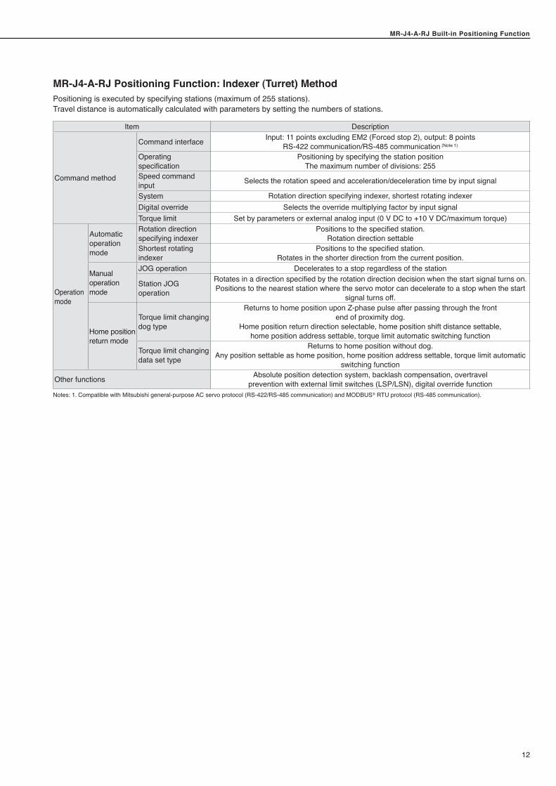
MR-J4-A-RJ Positioning Function: Indexer (Turret) MethodPositioning is executed by specifying stations (maximum of 255 stations).Travel distance is automatically calculated with parameters by setting the numbers of stations.
Item Description
Command method
Command interface Input: 11 points excluding EM2 (Forced stop 2), output: 8 points RS-422 communication/RS-485 communication (Note 1)
Operating specification
Positioning by specifying the station positionThe maximum number of divisions: 255
Speed command input Selects the rotation speed and acceleration/deceleration time by input signal
System Rotation direction specifying indexer, shortest rotating indexerDigital override Selects the override multiplying factor by input signalTorque limit Set by parameters or external analog input (0 V DC to +10 V DC/maximum torque)
Operation mode
Automatic operation mode
Rotation direction specifying indexer
Positions to the specified station.Rotation direction settable
Shortest rotating indexer
Positions to the specified station.Rotates in the shorter direction from the current position.
Manual operation mode
JOG operation Decelerates to a stop regardless of the station
Station JOG operation
Rotates in a direction specified by the rotation direction decision when the start signal turns on.Positions to the nearest station where the servo motor can decelerate to a stop when the start
signal turns off.
Home position return mode
Torque limit changing dog type
Returns to home position upon Z-phase pulse after passing through the front end of proximity dog.
Home position return direction selectable, home position shift distance settable,home position address settable, torque limit automatic switching function
Torque limit changing data set type
Returns to home position without dog.Any position settable as home position, home position address settable, torque limit automatic
switching function
Other functions Absolute position detection system, backlash compensation, overtravelprevention with external limit switches (LSP/LSN), digital override function
Notes: 1. Compatible with Mitsubishi general-purpose AC servo protocol (RS-422/RS-485 communication) and MODBUS® RTU protocol (RS-485 communication).
MR-J4-A-RJ Built-in Positioning Function
13
MR-J4-A-RJ Built-in Positioning Function
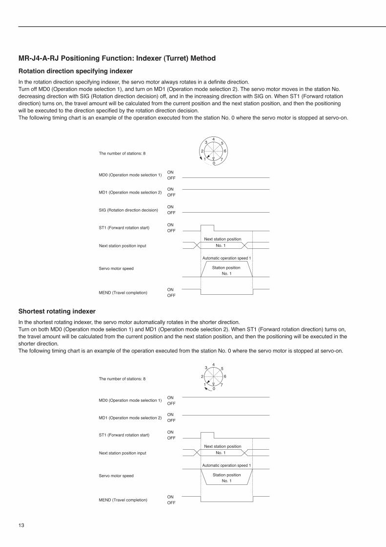
MR-J4-A-RJ Positioning Function: Indexer (Turret) MethodRotation direction specifying indexerIn the rotation direction specifying indexer, the servo motor always rotates in a definite direction.Turn off MD0 (Operation mode selection 1), and turn on MD1 (Operation mode selection 2). The servo motor moves in the station No. decreasing direction with SIG (Rotation direction decision) off, and in the increasing direction with SIG on. When ST1 (Forward rotation direction) turns on, the travel amount will be calculated from the current position and the next station position, and then the positioning will be executed to the direction specified by the rotation direction decision.The following timing chart is an example of the operation executed from the station No. 0 where the servo motor is stopped at servo-on.
Shortest rotating indexerIn the shortest rotating indexer, the servo motor automatically rotates in the shorter direction.Turn on both MD0 (Operation mode selection 1) and MD1 (Operation mode selection 2). When ST1 (Forward rotation direction) turns on, the travel amount will be calculated from the current position and the next station position, and then the positioning will be executed in the shorter direction.The following timing chart is an example of the operation executed from the station No. 0 where the servo motor is stopped at servo-on.
Next station position
Automatic operation speed 1
No. 1
The number of stations: 8
MEND (Travel completion)
Next station position input
Servo motor speed
ST1 (Forward rotation start)
MD0 (Operation mode selection 1)
MD1 (Operation mode selection 2)
ONOFF
ONOFF
ONOFF
ONOFF
SIG (Rotation direction decision)ONOFF
Station position No. 1
01
2
34
5
6
7
Next station position
Automatic operation speed 1
No. 1
ONOFF
ONOFF
ONOFF
ONOFF
Station positionNo. 1
01
2
34
5
6
7The number of stations: 8
MEND (Travel completion)
Next station position input
Servo motor speed
ST1 (Forward rotation start)
MD0 (Operation mode selection 1)
MD1 (Operation mode selection 2)
MR-J4-A-RJ Built-in Positioning FunctionMR-J4-A-RJ Built-in Positioning Function
14
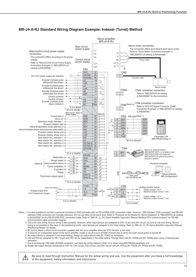
MR-J4-A-RJ Standard Wiring Diagram Example: Indexer (Turret) Method
(Note 2)C
N5
CN8 (Note 3)
CN2L
CN2
L1L2L3
L11L21
EM2 42
DI3 (Note 6) 35DI2 (Note 6) 10
SON 15MD0 16
18ST1MD1SIGLSP
17
4543
LSN 44DI0 19DI1 41
DOCOM 47
DICOM 21ALM 48
ZP 23MEND 25
CPO 22
24INP49RD1314
DICOMDOCOM
204689456
LZ
7
LZRLA
34
LAR
33
LBLBR
LGOPSD
CN6
CN3SDPSDNRDPRDNLGLG
TRE
5436178
RDPRDNSDPSDNGNDGND
RS-422
MO13LG1
MO22
RA1
RA2
RA3
RA4
RA5
RA6
CN1
(Note 5) (Note 5)
UVW
Main/control circuit power supply connection
The connection differs according to the power voltage.Refer to "Main/Control Circuit Power Supply Connection Example" in "MELSERVO-J4 catalog (L(NA)03058)."
Main circuit power supply
Control circuit power supply
Encoder Z-phase pulse(differential line driver)
Encoder Z-phase pulse(Open collector)
Encoder A-phase pulse(differential line driver)
Encoder B-phase pulse(differential line driver)
Control commonControl common
24 V DC power supply for interface
2 m or shorter10 m or shorter
Plate
Forced stop 2Servo-on
Operation mode selection 1
Operation mode selection 2Forward rotation start
External limit/rotation direction decision/automatic speed selectionForward rotation stroke endReverse rotation stroke endNext station No. selection 1Next station No. selection 2Next station No. selection 3Next station No. selection 4
Main circuit power supply
(Note 4)
MalfunctionRough match
Travel completionHome position return
In-positionReady
Preliminary output signal
(Note 8)
(Note 8)
10 m or shorter
10 m or shorter
P15R 1
27LGTLA
28
SD Plate
Analog torque limit+10 V/maximum torque
Upper limit setting
2 m or shorter
USB cableMR-J3USBCBL3M
CN4BATLG
12
Mount an optional battery (MR-BAT6V1SET), or a battery case (MR-BT6VCASE) and batteries (MR-BAT6V1) for absolute position detection system.
Setup softwareMR Configurator2
Personal computer
Analog monitor outputOutput voltage: ±10 VMaximum output current: 1 mA
Output voltage: ±10 VMaximum output current: 1 mA
2 m or shorter
30 m or shorter
(Note 1)
CN8 connector connectionRefer to "STO I/O Signal Connector (CN8) Connection Example" in "MELSERVO-J4 catalog (L(NA)03058)."
CN2L connector connectionRefer to "MELSERVO-J4 catalog (L(NA)03058)" for the connection.
Encoder cable
Power cable
Servo motor
Servo motor connection The connection differs according to each servo motor.Refer to "Servo Motor Connection Example" in "MELSERVO-J4 catalog (L(NA)03058)."
Servo amplifierMR-J4-A-RJ
OPC 12
Parameter unitMR-PRU03 (Note 7)
Notes: 1. It is also possible to connect a personal computer to CN3 connector with an RS-422/RS-232C conversion cable. However, USB interface (CN5 connector) and RS-422 interface (CN3 connector) are mutually exclusive. Do not use them at the same time. Refer to "Products on the Market for Servo Amplifiers" in "MELSERVO-J4 catalog (L(NA)03058)" for the RS-422/RS-232C conversion cable. Refer to "MR-J4-_A_-RJ Servo Amplifier Instruction Manual (Modbus-RTU communication)" for RS-485 communication cable connection diagram.
2. This is for sink wiring. Source wiring is also possible. However, when input devices are assigned to CN1-10 pin and CN1-35 pin, be sure to use sink wiring. Source wiring is not possible in this case. In the positioning mode, input devices are assigned in the initial setting. Refer to "MR-J4-_A_-RJ Servo Amplifier Instruction Manual (Positioning Mode)" for details.
3. Be sure to attach a short-circuit connector supplied with the servo amplifier when the STO function is not used. 4. To prevent an unexpected restart of the servo amplifier, create a circuit to turn off EM2 (Forced stop 2) when the main circuit power is turned off. 5. No output device is assigned in the initial setting. Assign an output device with [Pr. PD47] as necessary. 6. DI2 and DI3 are assigned to CN1-10 pin and CN1-35 pin respectively in the initial setting. Change them with [Pr. PD44] and [Pr. PD46] when using a manual pulse
generator. 7. Use a commercial LAN cable (EIA568 compliant), and keep the wiring distance within 10 m when using MR-PRU03 parameter unit. 8. Assign the output devices mentioned to CN1-18, CN1-22 pin, CN1-23 pin, and CN1-25 pin with [Pr. PD10], [Pr. PD23], [Pr. PD24] and [Pr. PD26].
Be sure to read through Instruction Manual for the actual wiring and use. Use the equipment after you have a full knowledge of the equipment, safety information and instructions.
MR-J4-A-RJ Built-in Positioning Function
15
MR-J4-A-RJ Built-in Positioning Function
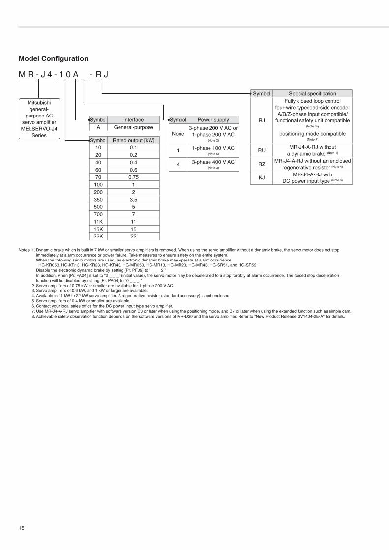
Notes: 1. Dynamic brake which is built in 7 kW or smaller servo amplifiers is removed. When using the servo amplifier without a dynamic brake, the servo motor does not stop immediately at alarm occurrence or power failure. Take measures to ensure safety on the entire system.
When the following servo motors are used, an electronic dynamic brake may operate at alarm occurrence. HG-KR053, HG-KR13, HG-KR23, HG-KR43, HG-MR053, HG-MR13, HG-MR23, HG-MR43, HG-SR51, and HG-SR52 Disable the electronic dynamic brake by setting [Pr. PF09] to "_ _ _ 2." In addition, when [Pr. PA04] is set to "2 _ _ _" (initial value), the servo motor may be decelerated to a stop forcibly at alarm occurrence. The forced stop deceleration
function will be disabled by setting [Pr. PA04] to "0 _ _ _." 2. Servo amplifiers of 0.75 kW or smaller are available for 1-phase 200 V AC. 3. Servo amplifiers of 0.6 kW, and 1 kW or larger are available. 4. Available in 11 kW to 22 kW servo amplifier. A regenerative resistor (standard accessory) is not enclosed. 5. Servo amplifiers of 0.4 kW or smaller are available. 6. Contact your local sales office for the DC power input type servo amplifier. 7. Use MR-J4-A-RJ servo amplifier with software version B3 or later when using the positioning mode, and B7 or later when using the extended function such as simple cam. 8. Achievable safety observation function depends on the software versions of MR-D30 and the servo amplifier. Refer to "New Product Release SV1404-2E-A" for details.
Model Configuration
M R - J 4 - 1 0 A - R J
Symbol Rated output [kW]10 0.120 0.240 0.460 0.670 0.75100 1200 2350 3.5500 5700 711K 1115K 1522K 22
Symbol InterfaceA General-purpose
Symbol Special specification
RJ
Fully closed loop control four-wire type/load-side encoder A/B/Z-phase input compatible/
functional safety unit compatible
(Note 8)/ positioning mode compatible
(Note 7)
RU MR-J4-A-RJ without a dynamic brake (Note 1)
RZ MR-J4-A-RJ without an enclosed regenerative resistor (Note 4)
KJ MR-J4-A-RJ with DC power input type (Note 6)
Symbol Power supply
None3-phase 200 V AC or
1-phase 200 V AC (Note 2)
1 1-phase 100 V AC (Note 5)
4 3-phase 400 V AC (Note 3)
Mitsubishi general-
purpose AC servo amplifier MELSERVO-J4
Series
MR-J4-A-RJ Built-in Positioning FunctionMR-J4-A-RJ Built-in Positioning Function
16
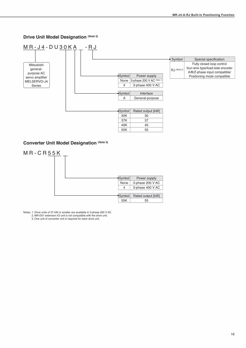
Symbol Power supplyNone 3-phase 200 V AC
4 3-phase 400 V AC
Drive Unit Model Designation (Note 3)
M R - J 4 - D U 3 0 K A - R J
Converter Unit Model Designation (Note 3)
M R - C R 5 5 K
Symbol Rated output [kW]30K 3037K 3745K 4555K 55
Symbol Rated output [kW]55K 55
Symbol InterfaceA General-purpose
Symbol Special specification
RJ (Note 2)
Fully closed loop control four-wire type/load-side encoder A/B/Z-phase input compatible/ Positioning mode compatible
Mitsubishi general-
purpose AC servo amplifier MELSERVO-J4
Series
Notes: 1. Drive units of 37 kW or smaller are available in 3-phase 200 V AC. 2. MR-D01 extension IO unit is not compatible with the drive unit. 3. One unit of converter unit is required for each drive unit.
Symbol Power supplyNone 3-phase 200 V AC (Note 1)
4 3-phase 400 V AC
MR-J4-A-RJ Built-in Positioning Function
17
MR-J4-A-RJ Built-in Positioning Function
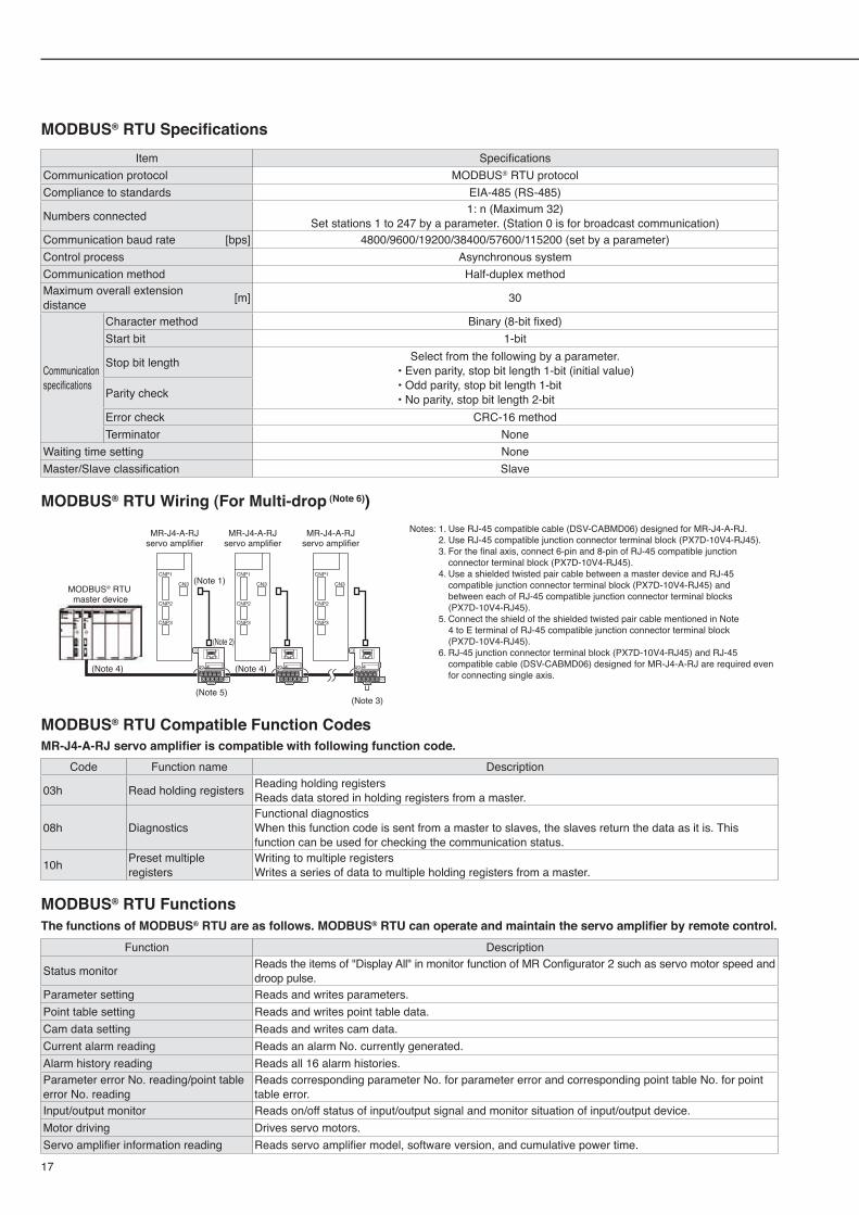
MODBUS® RTU SpecificationsItem Specifications
Communication protocol MODBUS® RTU protocolCompliance to standards EIA-485 (RS-485)
Numbers connected 1: n (Maximum 32)Set stations 1 to 247 by a parameter. (Station 0 is for broadcast communication)
Communication baud rate [bps] 4800/9600/19200/38400/57600/115200 (set by a parameter)Control process Asynchronous systemCommunication method Half-duplex methodMaximum overall extension distance [m] 30
Communication specifications
Character method Binary (8-bit fixed)Start bit 1-bit
Stop bit length Select from the following by a parameter.• Even parity, stop bit length 1-bit (initial value)• Odd parity, stop bit length 1-bit• No parity, stop bit length 2-bitParity check
Error check CRC-16 methodTerminator None
Waiting time setting NoneMaster/Slave classification Slave
MODBUS® RTU Wiring (For Multi-drop (Note 6))
(Note 3)(Note 5)
MR-J4-A-RJservo amplifier
(Note 1)
(Note 2)
MR-J4-A-RJservo amplifier
MR-J4-A-RJservo amplifier
(Note 4) (Note 4)
CNP1
CNP2
CNP3
CN3
CNP1
CNP2
CNP3
CN3
CNP1
CNP2
CNP3
CN3MODBUS® RTU master device
Notes: 1. Use RJ-45 compatible cable (DSV-CABMD06) designed for MR-J4-A-RJ. 2. Use RJ-45 compatible junction connector terminal block (PX7D-10V4-RJ45). 3. For the final axis, connect 6-pin and 8-pin of RJ-45 compatible junction
connector terminal block (PX7D-10V4-RJ45). 4. Use a shielded twisted pair cable between a master device and RJ-45
compatible junction connector terminal block (PX7D-10V4-RJ45) and between each of RJ-45 compatible junction connector terminal blocks (PX7D-10V4-RJ45).
5. Connect the shield of the shielded twisted pair cable mentioned in Note 4 to E terminal of RJ-45 compatible junction connector terminal block (PX7D-10V4-RJ45).
6. RJ-45 junction connector terminal block (PX7D-10V4-RJ45) and RJ-45 compatible cable (DSV-CABMD06) designed for MR-J4-A-RJ are required even for connecting single axis.
MODBUS® RTU Compatible Function CodesMR-J4-A-RJ servo amplifier is compatible with following function code.
Code Function name Description
03h Read holding registers Reading holding registersReads data stored in holding registers from a master.
08h DiagnosticsFunctional diagnosticsWhen this function code is sent from a master to slaves, the slaves return the data as it is. This function can be used for checking the communication status.
10h Preset multiple registers
Writing to multiple registersWrites a series of data to multiple holding registers from a master.
MODBUS® RTU FunctionsThe functions of MODBUS® RTU are as follows. MODBUS® RTU can operate and maintain the servo amplifier by remote control.
Function Description
Status monitor Reads the items of "Display All" in monitor function of MR Configurator 2 such as servo motor speed and droop pulse.
Parameter setting Reads and writes parameters.Point table setting Reads and writes point table data.Cam data setting Reads and writes cam data.Current alarm reading Reads an alarm No. currently generated.Alarm history reading Reads all 16 alarm histories.Parameter error No. reading/point table error No. reading
Reads corresponding parameter No. for parameter error and corresponding point table No. for point table error.
Input/output monitor Reads on/off status of input/output signal and monitor situation of input/output device.Motor driving Drives servo motors.Servo amplifier information reading Reads servo amplifier model, software version, and cumulative power time.
MR-J4-A-RJ Built-in Positioning FunctionMR-J4-A-RJ Built-in Positioning Function
18
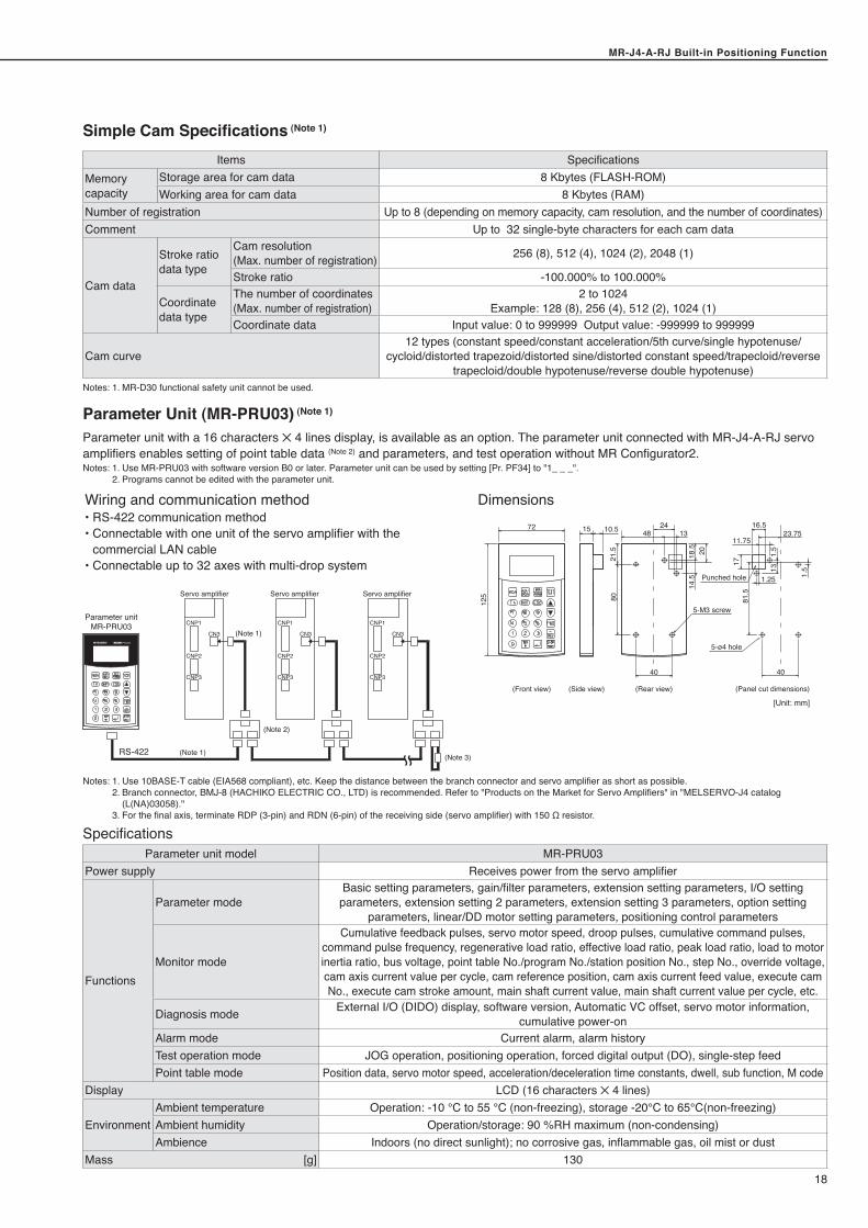
Simple Cam Specifications (Note 1)
Items SpecificationsMemory capacity
Storage area for cam data 8 Kbytes (FLASH-ROM)Working area for cam data 8 Kbytes (RAM)
Number of registration Up to 8 (depending on memory capacity, cam resolution, and the number of coordinates)Comment Up to 32 single-byte characters for each cam data
Cam data
Stroke ratio data type
Cam resolution (Max. number of registration) 256 (8), 512 (4), 1024 (2), 2048 (1)
Stroke ratio -100.000% to 100.000%
Coordinate data type
The number of coordinates (Max. number of registration)
2 to 1024 Example: 128 (8), 256 (4), 512 (2), 1024 (1)
Coordinate data Input value: 0 to 999999 Output value: -999999 to 999999
Cam curve12 types (constant speed/constant acceleration/5th curve/single hypotenuse/
cycloid/distorted trapezoid/distorted sine/distorted constant speed/trapecloid/reverse trapecloid/double hypotenuse/reverse double hypotenuse)
Notes: 1. MR-D30 functional safety unit cannot be used.
Parameter Unit (MR-PRU03) (Note 1)
Parameter unit with a 16 characters 5 4 lines display, is available as an option. The parameter unit connected with MR-J4-A-RJ servo amplifiers enables setting of point table data (Note 2) and parameters, and test operation without MR Configurator2.Notes: 1. Use MR-PRU03 with software version B0 or later. Parameter unit can be used by setting [Pr. PF34] to "1_ _ _". 2. Programs cannot be edited with the parameter unit.
Wiring and communication method Dimensions• RS-422 communication method• Connectable with one unit of the servo amplifier with the commercial LAN cable• Connectable up to 32 axes with multi-drop system
125
21.5 2018.5
14.5
80
17
1.5
81.5
72 15 10.5 48 1324
40
5-M3 screw
5-ø4 hole
40
16.5
11.7523.75
1.25
(Front view) (Side view) (Rear view) (Panel cut dimensions)
1.5
13
Punched hole
[Unit: mm]
Servo amplifier Servo amplifier Servo amplifier
CNP1
CNP2
CNP3
CN3
CNP1
CNP2
CNP3
CN3
CNP1
CNP2
CNP3
CN3
Parameter unitMR-PRU03
RS-422
(Note 2)
(Note 1)
(Note 1)
(Note 3)
Notes: 1. Use 10BASE-T cable (EIA568 compliant), etc. Keep the distance between the branch connector and servo amplifier as short as possible. 2. Branch connector, BMJ-8 (HACHIKO ELECTRIC CO., LTD) is recommended. Refer to "Products on the Market for Servo Amplifiers" in "MELSERVO-J4 catalog
(L(NA)03058)." 3. For the final axis, terminate RDP (3-pin) and RDN (6-pin) of the receiving side (servo amplifier) with 150 Ω resistor.
SpecificationsParameter unit model MR-PRU03
Power supply Receives power from the servo amplifier
Functions
Parameter modeBasic setting parameters, gain/filter parameters, extension setting parameters, I/O setting
parameters, extension setting 2 parameters, extension setting 3 parameters, option setting parameters, linear/DD motor setting parameters, positioning control parameters
Monitor mode
Cumulative feedback pulses, servo motor speed, droop pulses, cumulative command pulses, command pulse frequency, regenerative load ratio, effective load ratio, peak load ratio, load to motor inertia ratio, bus voltage, point table No./program No./station position No., step No., override voltage, cam axis current value per cycle, cam reference position, cam axis current feed value, execute cam No., execute cam stroke amount, main shaft current value, main shaft current value per cycle, etc.
Diagnosis mode External I/O (DIDO) display, software version, Automatic VC offset, servo motor information, cumulative power-on
Alarm mode Current alarm, alarm historyTest operation mode JOG operation, positioning operation, forced digital output (DO), single-step feed Point table mode Position data, servo motor speed, acceleration/deceleration time constants, dwell, sub function, M code
Display LCD (16 characters 5 4 lines)
EnvironmentAmbient temperature Operation: -10 °C to 55 ℃ (non-freezing), storage -20°C to 65°C(non-freezing)Ambient humidity Operation/storage: 90 %RH maximum (non-condensing)Ambience Indoors (no direct sunlight); no corrosive gas, inflammable gas, oil mist or dust
Mass [g] 130
MR-J4-A-RJ Built-in Positioning Function
19
MR-J4-A-RJ Built-in Positioning Function
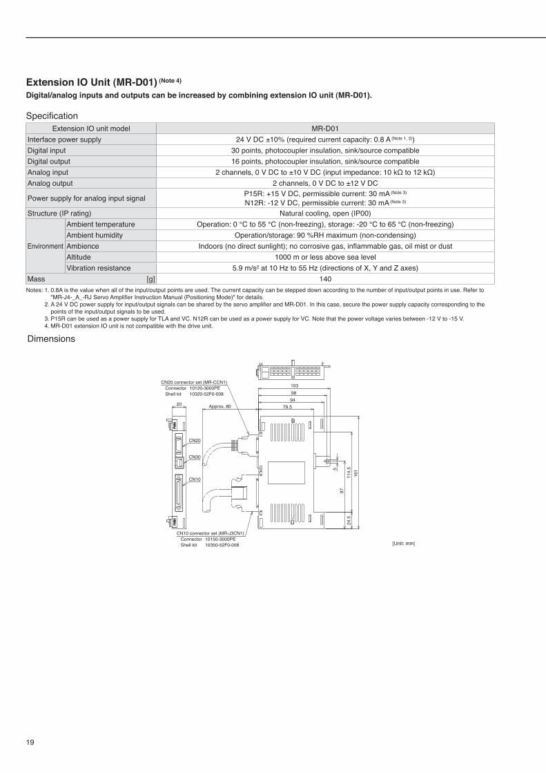
Extension IO Unit (MR-D01) (Note 4)
Digital/analog inputs and outputs can be increased by combining extension IO unit (MR-D01).
SpecificationExtension IO unit model MR-D01
Interface power supply 24 V DC ±10% (required current capacity: 0.8 A (Note 1, 2))Digital input 30 points, photocoupler insulation, sink/source compatibleDigital output 16 points, photocoupler insulation, sink/source compatibleAnalog input 2 channels, 0 V DC to ±10 V DC (input impedance: 10 kΩ to 12 kΩ)Analog output 2 channels, 0 V DC to ±12 V DC
Power supply for analog input signal P15R: +15 V DC, permissible current: 30 mA (Note 3)
N12R: -12 V DC, permissible current: 30 mA (Note 3)
Structure (IP rating) Natural cooling, open (IP00)
Environment
Ambient temperature Operation: 0 °C to 55 °C (non-freezing), storage: -20 °C to 65 °C (non-freezing)Ambient humidity Operation/storage: 90 %RH maximum (non-condensing)Ambience Indoors (no direct sunlight); no corrosive gas, inflammable gas, oil mist or dustAltitude 1000 m or less above sea levelVibration resistance 5.9 m/s2 at 10 Hz to 55 Hz (directions of X, Y and Z axes)
Mass [g] 140Notes: 1. 0.8A is the value when all of the input/output points are used. The current capacity can be stepped down according to the number of input/output points in use. Refer to
"MR-J4-_A_-RJ Servo Amplifier Instruction Manual (Positioning Mode)" for details. 2. A 24 V DC power supply for input/output signals can be shared by the servo amplifier and MR-D01. In this case, secure the power supply capacity corresponding to the
points of the input/output signals to be used. 3. P15R can be used as a power supply for TLA and VC. N12R can be used as a power supply for VC. Note that the power voltage varies between -12 V to -15 V. 4. MR-D01 extension IO unit is not compatible with the drive unit.
Dimensions
Approx. 80
CN20 connector set (MR-CCN1) Connector 10120-3000PE Shell kit 10320-52F0-008
CN10 connector set (MR-J3CN1) Connector 10150-3000PE Shell kit 10350-52F0-008
CN20
20
1039894
79.5
161
114.
5597
24.5
CN30
CN10
[Unit: mm]
MR-J4-A-RJ Built-in Positioning FunctionMR-J4-A-RJ Built-in Positioning Function
20
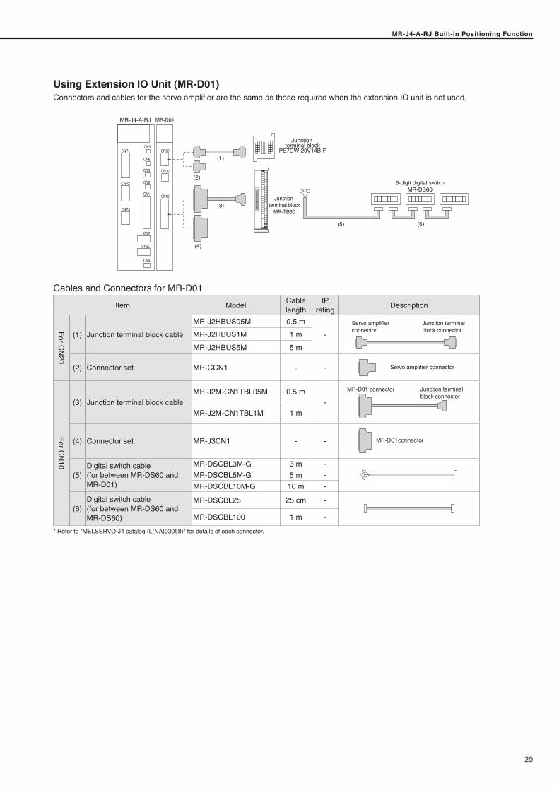
Using Extension IO Unit (MR-D01)Connectors and cables for the servo amplifier are the same as those required when the extension IO unit is not used.
Junction terminal block
MR-TB50
6-digit digital switchMR-DS60
Junction terminal block
PS7DW-20V14B-F
(5)
(1)
(3)
(2)
(4)
(6)
MR-J4-A-RJ MR-D01
CN5CN20
CN30
CN10
CN6
CN3
CN8
CN1
CN2
CN4
CNP2
CNP1
CNP3
CN2L
Cables and Connectors for MR-D01Item Model Cable
lengthIP
rating Description
For CN
20
(1) Junction terminal block cableMR-J2HBUS05M 0.5 m
-Servo amplifier connector
Junction terminal block connectorMR-J2HBUS1M 1 m
MR-J2HBUS5M 5 m
(2) Connector set MR-CCN1 - - Servo amplifier connector
For CN
10
(3) Junction terminal block cableMR-J2M-CN1TBL05M 0.5 m
-
Junction terminal block connector
MR-D01 connector
MR-J2M-CN1TBL1M 1 m
(4) Connector set MR-J3CN1 - - MR-D01connector
(5)Digital switch cable(for between MR-DS60 and MR-D01)
MR-DSCBL3M-G 3 m -MR-DSCBL5M-G 5 m -MR-DSCBL10M-G 10 m -
(6)Digital switch cable(for between MR-DS60 and MR-DS60)
MR-DSCBL25 25 cm -
MR-DSCBL100 1 m -
* Refer to "MELSERVO-J4 catalog (L(NA)03058)" for details of each connector.
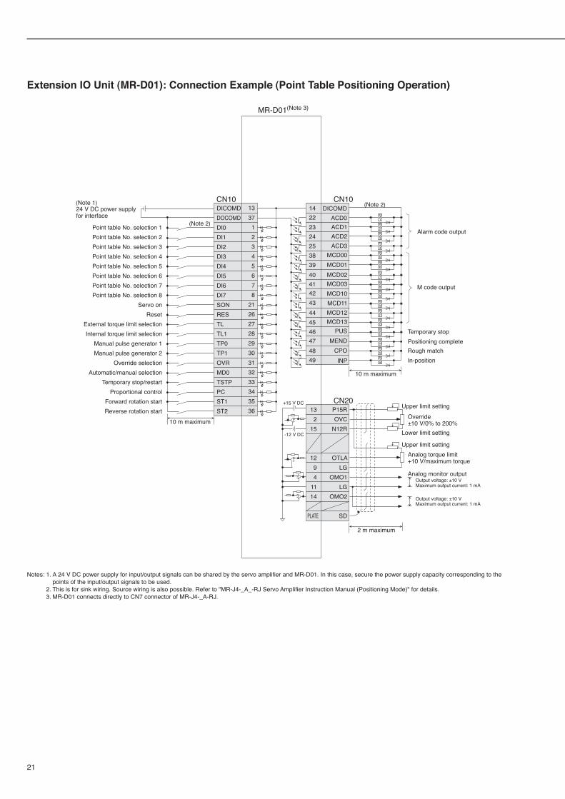
MR-J4-A-RJ Built-in Positioning Function
21
MR-J4-A-RJ Built-in Positioning Function
Extension IO Unit (MR-D01): Connection Example (Point Table Positioning Operation)
+15 V DC
-12 V DC
Output voltage: ±10 VMaximum output current: 1 mA
Analog monitor output
Output voltage: ±10 VMaximum output current: 1 mA
CN101422232425383940414243444546474849
(Note 2)
10 m maximum
Alarm code output
M code output
Temporary stopPositioning completeRough matchIn-position
CN10DICOMDDOCOMDDI0DI1DI2DI3DI4DI5DI6DI7SONRESTLTL1TP0TP1OVRMD0TSTPPCST1ST2
133712345678
212627282930313233343536
10 m maximum
Point table No. selection 1Point table No. selection 2Point table No. selection 3Point table No. selection 4Point table No. selection 5Point table No. selection 6Point table No. selection 7Point table No. selection 8
Servo onReset
External torque limit selectionInternal torque limit selection
Manual pulse generator 1Manual pulse generator 2
Override selectionAutomatic/manual selection
Temporary stop/restartProportional control
Forward rotation startReverse rotation start
(Note 2)
MR-D01(Note 3)
DICOMDACD0ACD1ACD2ACD3
MCD00MCD01
MCD03
MCD11
MCD13PUS
INPCPO
MEND
MCD02
MCD10
MCD12
CN20P15ROVC
N12R
OTLALG
OMO1LG
OMO2
SD
132
15
1294
1114
PLATE
Upper limit settingOverride±10 V/0% to 200%
Analog torque limit+10 V/maximum torque
Upper limit setting
Lower limit setting
2 m maximum
(Note 1)24 V DC power supplyfor interface R
A1RA2RA3
RA4RA5RA6
RA7RA8RA9
RA10RA11RA12
RA13RA14RA15
RA16
Notes: 1. A 24 V DC power supply for input/output signals can be shared by the servo amplifier and MR-D01. In this case, secure the power supply capacity corresponding to the points of the input/output signals to be used.
2. This is for sink wiring. Source wiring is also possible. Refer to "MR-J4-_A_-RJ Servo Amplifier Instruction Manual (Positioning Mode)" for details. 3. MR-D01 connects directly to CN7 connector of MR-J4-_A-RJ.
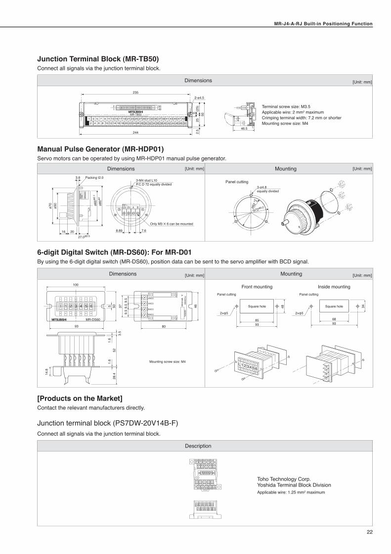
MR-J4-A-RJ Built-in Positioning FunctionMR-J4-A-RJ Built-in Positioning Function
22
Junction Terminal Block (MR-TB50)Connect all signals via the junction terminal block.
Dimensions [Unit: mm]
5049
2-ø4.5
92.
525
(25)
50MR-TB50
2 4 6 8 10 12 14 16 18 20 22 24 26 28 30 32 34 36 38 40 42 44 46 48 501 3 5 7 9 11 13 15 17 19 21 23 25 27 29 31 33 35 37 39 41 43 45 47 49
21
46.5244
235
Manual Pulse Generator (MR-HDP01)Servo motors can be operated by using MR-HDP01 manual pulse generator.
Dimensions [Unit: mm] Mounting [Unit: mm]
8.89 7.6
12V 0V A B5V
3-M4 stud L10P.C.D 72 equally divided
MAN
UAL
TYPE
SERI
ALNO
.
ø50
ø70
3.6
16 2027.0±0.5
Only M3 ✕ 6 can be mounted
Packing t2.0
ø80±
1ø6
0±0.
1
ø62
+2 0
ø72±0.2
3-ø4.8equally divided
Panel cutting
6-digit Digital Switch (MR-DS60): For MR-D01By using the 6-digit digital switch (MR-DS60), position data can be sent to the servo amplifier with BCD signal.
Dimensions [Unit: mm] Mounting [Unit: mm]
100
MR-DS60
93
14.8
28.4
521.
61.
65 50 37
9.5
9.5 46
80
9.5
3.5
COM1
CO
N1
CO
N2 M
R-D
S60PC
�3963SER
IAL
1A1B
1A1B
COM1
COM2
COM2
1 2 3 4 5 6
Mounting screw size: M4
2×φ5 2×φ5
Panel cutting
Square hole Square hole
85
48 34
6893 93
Panel cutting
L 1 2 3 4 5 6
Inside mountingFront mounting
[Products on the Market]Contact the relevant manufacturers directly.
Junction terminal block (PS7DW-20V14B-F)Connect all signals via the junction terminal block.
Description
Toho Technology Corp.Yoshida Terminal Block DivisionApplicable wire: 1.25 mm2 maximum
Terminal screw size: M3.5Applicable wire: 2 mm2 maximumCrimping terminal width: 7.2 mm or shorterMounting screw size: M4
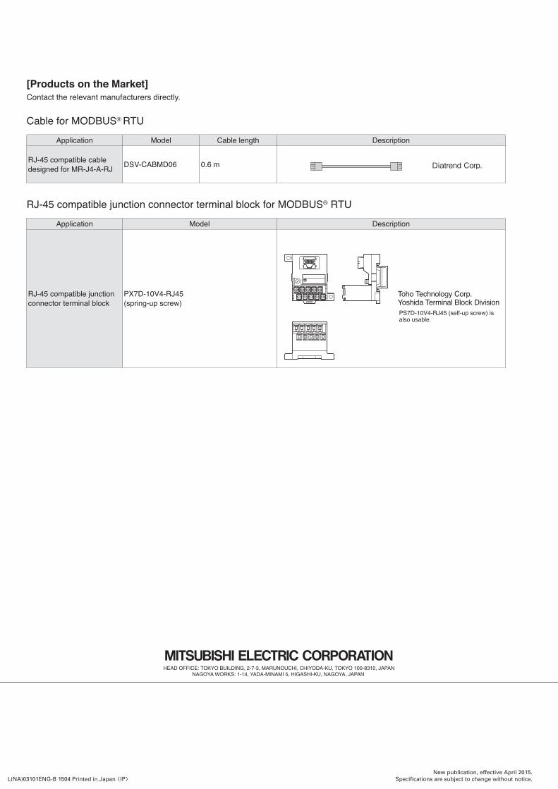
New publication, effective April 2015.Specifications are subject to change without notice.L(NA)03101ENG-B 1504 Printed in Japan [IP]
[Products on the Market]Contact the relevant manufacturers directly.
Cable for MODBUS® RTUApplication Model Cable length Description
RJ-45 compatible cable designed for MR-J4-A-RJ DSV-CABMD06 0.6 m Diatrend Corp.
RJ-45 compatible junction connector terminal block for MODBUS® RTUApplication Model Description
RJ-45 compatible junction connector terminal block
PX7D-10V4-RJ45 (spring-up screw)
Toho Technology Corp.Yoshida Terminal Block DivisionPS7D-10V4-RJ45 (self-up screw) is also usable.


![MELSERVO-J4 Series with Built-in Positioning …dl.mitsubishielectric.co.jp/dl/fa/document/catalog/servo/...[Point table] window on MR Configurator2 MR-J4-A-RJ MR-J4-A-RJ is now available](https://img.pdfslide.us/doc/110x75/5aae50927f8b9adb688c2a4e/melservo-j4-series-with-built-in-positioning-dl-point-table-window-on-mr-configurator2.jpg)


![MELSERVO-J4 Solutions€¦ · FR-CV series LX-050TD Motion CPU I/O module Analog input module Tension meter Q172DSCPU QX40,QY40P Q64AD ... (HF-KP series)] [Prior model (HG-KR series)]](https://img.pdfslide.us/doc/110x75/5f669639fc3de013e84e2909/melservo-j4-fr-cv-series-lx-050td-motion-cpu-io-module-analog-input-module-tension.jpg)